US5912791A - Landing zone design for a magnetic disc - Google Patents
Landing zone design for a magnetic discDownload PDFInfo
- Publication number
- US5912791A US5912791AUS08/876,215US87621597AUS5912791AUS 5912791 AUS5912791 AUS 5912791AUS 87621597 AUS87621597 AUS 87621597AUS 5912791 AUS5912791 AUS 5912791A
- Authority
- US
- United States
- Prior art keywords
- disc
- depressions
- data
- slider
- landing zone
- Prior art date
- Legal status (The legal status is an assumption and is not a legal conclusion. Google has not performed a legal analysis and makes no representation as to the accuracy of the status listed.)
- Expired - Fee Related
Links
Images


Classifications
- G—PHYSICS
- G11—INFORMATION STORAGE
- G11B—INFORMATION STORAGE BASED ON RELATIVE MOVEMENT BETWEEN RECORD CARRIER AND TRANSDUCER
- G11B5/00—Recording by magnetisation or demagnetisation of a record carrier; Reproducing by magnetic means; Record carriers therefor
- G11B5/74—Record carriers characterised by the form, e.g. sheet shaped to wrap around a drum
- G11B5/82—Disk carriers
- G—PHYSICS
- G11—INFORMATION STORAGE
- G11B—INFORMATION STORAGE BASED ON RELATIVE MOVEMENT BETWEEN RECORD CARRIER AND TRANSDUCER
- G11B23/00—Record carriers not specific to the method of recording or reproducing; Accessories, e.g. containers, specially adapted for co-operation with the recording or reproducing apparatus ; Intermediate mediums; Apparatus or processes specially adapted for their manufacture
- G11B23/0014—Record carriers not specific to the method of recording or reproducing; Accessories, e.g. containers, specially adapted for co-operation with the recording or reproducing apparatus ; Intermediate mediums; Apparatus or processes specially adapted for their manufacture record carriers not specifically of filamentary or web form
- G11B23/0021—Record carriers not specific to the method of recording or reproducing; Accessories, e.g. containers, specially adapted for co-operation with the recording or reproducing apparatus ; Intermediate mediums; Apparatus or processes specially adapted for their manufacture record carriers not specifically of filamentary or web form discs
- G11B23/0028—Details
- G11B23/0035—Details means incorporated in the disc, e.g. hub, to enable its guiding, loading or driving
- G—PHYSICS
- G11—INFORMATION STORAGE
- G11B—INFORMATION STORAGE BASED ON RELATIVE MOVEMENT BETWEEN RECORD CARRIER AND TRANSDUCER
- G11B21/00—Head arrangements not specific to the method of recording or reproducing
- G11B21/16—Supporting the heads; Supporting the sockets for plug-in heads
- G11B21/20—Supporting the heads; Supporting the sockets for plug-in heads while the head is in operative position but stationary or permitting minor movements to follow irregularities in surface of record carrier
- G11B21/21—Supporting the heads; Supporting the sockets for plug-in heads while the head is in operative position but stationary or permitting minor movements to follow irregularities in surface of record carrier with provision for maintaining desired spacing of head from record carrier, e.g. fluid-dynamic spacing, slider
- G—PHYSICS
- G11—INFORMATION STORAGE
- G11B—INFORMATION STORAGE BASED ON RELATIVE MOVEMENT BETWEEN RECORD CARRIER AND TRANSDUCER
- G11B21/00—Head arrangements not specific to the method of recording or reproducing
- G11B21/16—Supporting the heads; Supporting the sockets for plug-in heads
- G11B21/22—Supporting the heads; Supporting the sockets for plug-in heads while the head is out of operative position
- G—PHYSICS
- G11—INFORMATION STORAGE
- G11B—INFORMATION STORAGE BASED ON RELATIVE MOVEMENT BETWEEN RECORD CARRIER AND TRANSDUCER
- G11B5/00—Recording by magnetisation or demagnetisation of a record carrier; Reproducing by magnetic means; Record carriers therefor
- G11B5/48—Disposition or mounting of heads or head supports relative to record carriers ; arrangements of heads, e.g. for scanning the record carrier to increase the relative speed
- G11B5/54—Disposition or mounting of heads or head supports relative to record carriers ; arrangements of heads, e.g. for scanning the record carrier to increase the relative speed with provision for moving the head into or out of its operative position or across tracks
- G—PHYSICS
- G11—INFORMATION STORAGE
- G11B—INFORMATION STORAGE BASED ON RELATIVE MOVEMENT BETWEEN RECORD CARRIER AND TRANSDUCER
- G11B5/00—Recording by magnetisation or demagnetisation of a record carrier; Reproducing by magnetic means; Record carriers therefor
- G11B5/48—Disposition or mounting of heads or head supports relative to record carriers ; arrangements of heads, e.g. for scanning the record carrier to increase the relative speed
- G11B5/58—Disposition or mounting of heads or head supports relative to record carriers ; arrangements of heads, e.g. for scanning the record carrier to increase the relative speed with provision for moving the head for the purpose of maintaining alignment of the head relative to the record carrier during transducing operation, e.g. to compensate for surface irregularities of the latter or for track following
- G11B5/60—Fluid-dynamic spacing of heads from record-carriers
- G11B5/6005—Specially adapted for spacing from a rotating disc using a fluid cushion
- G—PHYSICS
- G11—INFORMATION STORAGE
- G11B—INFORMATION STORAGE BASED ON RELATIVE MOVEMENT BETWEEN RECORD CARRIER AND TRANSDUCER
- G11B5/00—Recording by magnetisation or demagnetisation of a record carrier; Reproducing by magnetic means; Record carriers therefor
- G11B5/62—Record carriers characterised by the selection of the material
- G11B5/73—Base layers, i.e. all non-magnetic layers lying under a lowermost magnetic recording layer, e.g. including any non-magnetic layer in between a first magnetic recording layer and either an underlying substrate or a soft magnetic underlayer
- G11B5/7368—Non-polymeric layer under the lowermost magnetic recording layer
- G—PHYSICS
- G11—INFORMATION STORAGE
- G11B—INFORMATION STORAGE BASED ON RELATIVE MOVEMENT BETWEEN RECORD CARRIER AND TRANSDUCER
- G11B5/00—Recording by magnetisation or demagnetisation of a record carrier; Reproducing by magnetic means; Record carriers therefor
- G11B5/62—Record carriers characterised by the selection of the material
- G11B5/73—Base layers, i.e. all non-magnetic layers lying under a lowermost magnetic recording layer, e.g. including any non-magnetic layer in between a first magnetic recording layer and either an underlying substrate or a soft magnetic underlayer
- G11B5/739—Magnetic recording media substrates
- G11B5/73911—Inorganic substrates
- G11B5/73913—Composites or coated substrates
- G—PHYSICS
- G11—INFORMATION STORAGE
- G11B—INFORMATION STORAGE BASED ON RELATIVE MOVEMENT BETWEEN RECORD CARRIER AND TRANSDUCER
- G11B5/00—Recording by magnetisation or demagnetisation of a record carrier; Reproducing by magnetic means; Record carriers therefor
- G11B5/62—Record carriers characterised by the selection of the material
- G11B5/73—Base layers, i.e. all non-magnetic layers lying under a lowermost magnetic recording layer, e.g. including any non-magnetic layer in between a first magnetic recording layer and either an underlying substrate or a soft magnetic underlayer
- G11B5/739—Magnetic recording media substrates
- G11B5/73911—Inorganic substrates
- G11B5/73917—Metallic substrates, i.e. elemental metal or metal alloy substrates
- G11B5/73919—Aluminium or titanium elemental or alloy substrates
- G—PHYSICS
- G11—INFORMATION STORAGE
- G11B—INFORMATION STORAGE BASED ON RELATIVE MOVEMENT BETWEEN RECORD CARRIER AND TRANSDUCER
- G11B5/00—Recording by magnetisation or demagnetisation of a record carrier; Reproducing by magnetic means; Record carriers therefor
- G11B5/62—Record carriers characterised by the selection of the material
- G11B5/73—Base layers, i.e. all non-magnetic layers lying under a lowermost magnetic recording layer, e.g. including any non-magnetic layer in between a first magnetic recording layer and either an underlying substrate or a soft magnetic underlayer
- G11B5/739—Magnetic recording media substrates
- G11B5/73911—Inorganic substrates
- G11B5/73921—Glass or ceramic substrates
- G—PHYSICS
- G11—INFORMATION STORAGE
- G11B—INFORMATION STORAGE BASED ON RELATIVE MOVEMENT BETWEEN RECORD CARRIER AND TRANSDUCER
- G11B5/00—Recording by magnetisation or demagnetisation of a record carrier; Reproducing by magnetic means; Record carriers therefor
- G11B5/84—Processes or apparatus specially adapted for manufacturing record carriers
- G11B5/8404—Processes or apparatus specially adapted for manufacturing record carriers manufacturing base layers
- G—PHYSICS
- G11—INFORMATION STORAGE
- G11B—INFORMATION STORAGE BASED ON RELATIVE MOVEMENT BETWEEN RECORD CARRIER AND TRANSDUCER
- G11B5/00—Recording by magnetisation or demagnetisation of a record carrier; Reproducing by magnetic means; Record carriers therefor
- G11B5/84—Processes or apparatus specially adapted for manufacturing record carriers
- G11B5/8408—Processes or apparatus specially adapted for manufacturing record carriers protecting the magnetic layer
- G—PHYSICS
- G11—INFORMATION STORAGE
- G11B—INFORMATION STORAGE BASED ON RELATIVE MOVEMENT BETWEEN RECORD CARRIER AND TRANSDUCER
- G11B21/00—Head arrangements not specific to the method of recording or reproducing
- G11B21/02—Driving or moving of heads
- G11B21/12—Raising and lowering; Back-spacing or forward-spacing along track; Returning to starting position otherwise than during transducing operation
- G—PHYSICS
- G11—INFORMATION STORAGE
- G11B—INFORMATION STORAGE BASED ON RELATIVE MOVEMENT BETWEEN RECORD CARRIER AND TRANSDUCER
- G11B33/00—Constructional parts, details or accessories not provided for in the other groups of this subclass
- G11B33/02—Cabinets; Cases; Stands; Disposition of apparatus therein or thereon
- G11B33/08—Insulation or absorption of undesired vibrations or sounds
- G—PHYSICS
- G11—INFORMATION STORAGE
- G11B—INFORMATION STORAGE BASED ON RELATIVE MOVEMENT BETWEEN RECORD CARRIER AND TRANSDUCER
- G11B5/00—Recording by magnetisation or demagnetisation of a record carrier; Reproducing by magnetic means; Record carriers therefor
- G11B5/48—Disposition or mounting of heads or head supports relative to record carriers ; arrangements of heads, e.g. for scanning the record carrier to increase the relative speed
- G11B5/54—Disposition or mounting of heads or head supports relative to record carriers ; arrangements of heads, e.g. for scanning the record carrier to increase the relative speed with provision for moving the head into or out of its operative position or across tracks
- G11B5/55—Track change, selection or acquisition by displacement of the head
- G11B5/5521—Track change, selection or acquisition by displacement of the head across disk tracks
- G11B5/5582—Track change, selection or acquisition by displacement of the head across disk tracks system adaptation for working during or after external perturbation, e.g. in the presence of a mechanical oscillation caused by a shock
- G—PHYSICS
- G11—INFORMATION STORAGE
- G11B—INFORMATION STORAGE BASED ON RELATIVE MOVEMENT BETWEEN RECORD CARRIER AND TRANSDUCER
- G11B5/00—Recording by magnetisation or demagnetisation of a record carrier; Reproducing by magnetic means; Record carriers therefor
- G11B5/48—Disposition or mounting of heads or head supports relative to record carriers ; arrangements of heads, e.g. for scanning the record carrier to increase the relative speed
- G11B5/58—Disposition or mounting of heads or head supports relative to record carriers ; arrangements of heads, e.g. for scanning the record carrier to increase the relative speed with provision for moving the head for the purpose of maintaining alignment of the head relative to the record carrier during transducing operation, e.g. to compensate for surface irregularities of the latter or for track following
- G11B5/60—Fluid-dynamic spacing of heads from record-carriers
- G11B5/6005—Specially adapted for spacing from a rotating disc using a fluid cushion
- G11B5/6011—Control of flying height
Definitions
- the present inventionrelates to a disc construction of a disc drive.
- the present inventionrelates to an improved disc surface design for a disc of a disc drive.
- Disc drivesare well known in the industry. Such drives use rigid discs coated with a magnetizable medium for storage of digital information in a plurality of concentric data tracks.
- disc drivesinclude a disc pack including a plurality of concentric discs mounted on a spindle motor which causes the disc to spin.
- the disc drivealso includes head gimbal assemblies aligned with each disc surface.
- the head gimbal assembliesinclude a disc head slider which supports transducers or magnetoresistive elements for reading and writing data to the data tracks of the disc surfaces.
- the sliderincludes an air bearing surface which faces the disc surface. As the disc rotates, the disc drags air onto the slider along the air bearing surface in a direction approximately parallel to the tangential velocity of the disc. As the air passes beneath the air bearing surface, the pressure between the disc and the air bearing surface increases, which creates a hydrodynamic lifting force that causes the slider to lift directly above the disc surface to read and write data to the surface of the discs.
- the sliderPrior to rotation of the disc, the slider rests on the disc surface. The slider is not lifted from the disc until the hydrodynamic lifting force, caused by rotation of the disc, is sufficient to overcome a preload force supplied to bias the slider toward the disc surface.
- the hydrodynamic properties of the sliderare affected by the speed of rotation of the disc, the design of the air bearing surface of the slider, and the preload force supplied to the head gimbal assembly.
- Known discsinclude both landing zones and data zones on a disc surface. Data is stored in the data zone. Landing zones are used to support the slider when the disc drive is not in operation and provide a takeoff and landing surface for the slider. Landing zones contain no data because repeat contact by the slider would eventually destroy any data stored.
- Textured landing zonesare known which provide a roughened surface for reducing stiction between the slider and the disc surface for takeoff.
- Landing zonesare also known which include bumps of different shapes and sizes formed on a disc surface by a laser technique or other technique to provide a surface for the slider to take off and land. Bumps provide lower contact area between the slider and disc surface to lower the stiction force holding the slider to the disc surface.
- Disc drivesare being designed which have lower slider fly heights. Disc storage space is also at a premium; and, thus, disc drives are designed to store data to edges of the data zone abutting the landing zone. Landing zones which are formed of bumps may interfere with the slider at lower fly heights when the slider is aligned to retrieve data at a transition zone at the edges of the landing and data zones. Interference of the slider with bumps at low fly heights may causes the bumps to deform, or may cause the head to crash. Bumps also interfere with the hydrodynamic air flow to the slider bearing surface, thus interfering with the flying characteristics of the slider. Repeat contact of the slider with the bumps during takeoff, and landing cause the bumps to deform under the stress of the slider over time, thus decreasing effectiveness of the bumps in reducing stiction.
- the present inventionrelates to an improved is landing surface for a landing zone of a data disc.
- the improved landing surfaceincludes a patterned surface structure having contact surfaces formed generally flush with the disc surface and depressions formed into the disc surface in a predefined spaced pattern and extending below the disc surface in a predefined spaced array pattern.
- the depressionsreduce the contact area of the slider with the disc surface, thus providing a lower stiction for the slider from the landing zone. It also alleviates concern about bumps interfering with the slider when the slider is positioned to retrieve data at the transition zone at the edge of the landing and data zones.
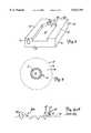
- FIG. 1is a schematic illustration of a disc drive.
- FIG. 2is a perspective view of a disc head slider, shown with the air bearing surface of the slider facing upwardly.
- FIG. 3is a schematic illustration of a magnetic disc having a landing zone and a data zone.
- FIGS. 4A-4Bare enlarged partial side-elevational views illustrating bumps formed in prior art landing zones.
- FIG. 4Cis an enlarged partial side-elevational view of an embodiment of an improved landing zone including contact surfaces and depressions.
- FIGS. 5A-5Billustrate formation of depressions by a laser technique in an embodiment of the improved landing surface of the present invention.
- FIGS. 5C-5Dillustrate the process of lapping raised portions of FIGS. 5A-5B formed by the laser technique for one embodiment of the improved landing surface of the present invention.
- FIGS. 5E-5Fillustrate formation of depressions by a laser technique of another embodiment of an improved landing surface of the present invention.
- FIGS. 5G-5Hillustrate the process of lapping raised portions and bumps of FIGS 5E-5F formed by the laser technique for another embodiment of the improved landing surface of the present invention.
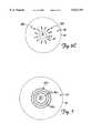
- FIGS. 6A-6Care schematic views illustrating various patterns of depressions in the disc surface of the improved landing zone.
- FIG. 7is a schematic view illustrating concentric ring depressions formed by a continuous laser process about the circumference of the disc.
- FIG. 1is a schematic view illustrating a disc drive 10.
- disc drive 10includes a housing 11 (shown schematically), disc 12, and a plurality of head gimbal assemblies (HGA) 18, which are supported relative to disc 12 and actuated by actuator assembly 20.
- the disc 12is supported for rotation about spindle axis 24 by a spindle motor 26.
- the head gimbal assemblies 18support a disc head slider via a gimbal spring (not shown) for reading and writing information to upper and lower disc surfaces 12a-12b in a known manner.
- the disc drive 10may include a plurality of discs 12 supported for co-rotation about spindle axis 24.
- the actuator assembly 20includes an actuator block 28 and actuator drive 30.
- Actuator block 28is rotationally coupled to housing 11 for operation about a pivot axis 32 in a known manner.
- a plurality of spaced stacked actuator arms 34a-bextend from the actuator block 28 in alignment with upper and lower disc surfaces 12a and 12b.
- the HGAs 18are coupled to actuator arms 34a-b via load beams 36.
- actuator arm 34asupports HGA 18 in alignment with an upper disc surface 12a
- actuator arm 34bsupports HGA 18 in alignment with a lower disc surface 12b.
- Actuator drive 30,which is typically a voice coil motor, pivots actuator block 28 about the pivot axis 32 for alignment with selected data tracks of disc 12. Operation of the spindle motor 26 and actuator drive 30 are controlled via control circuitry 40 of disc drive 10.
- additional actuator arms 34are included to support HGAs 18 relative to a plurality of discs 12.
- FIG. 2illustrates one embodiment of a slider 50 designed to fly above a disc surface.
- slider 50is formed of a rigid member including a leading edge 52, a trailing edge 54, an upper surface 56, and a lower air bearing surface 58.
- the upper surface 56is operably coupled to a gimbal spring (not shown) to flexibly support slider 50 to provide a resilient connection that allows the slider to pitch, roll and follow the topography of the disc surface in a known manner.
- the lower air bearing surface 58faces the disc surface and includes raised rails 60 and 62, cross rail 64, and a recessed subambient pressure cavity 66.
- Rotation of discs 12provides flow of air from the leading edge 52 towards the trailing edge 54 along the air bearing surface 58 of slider 50.
- the raised rails 60 and 62are positioned along opposed sides of the slider 50 and provide a high-pressure surface, and the recessed subambient pressure cavity 66 provides a low pressure surface for creating a hydrodynamic lifting force to lift the head gimbal assembly 18 to fly across the disc surface.
- the trailing edge 54includes an active transducer 70 formed at raised rails 60 or 62 for reading and writing data to the disc surface 12a, 12b.
- the active transduceris aligned on raised rail 60.
- the active transducer 70is positioned on either rail 60 or 62, depending upon whether the slider 50 is coupled to the upper or lower actuator arm 34a-b.
- Slider 50 in FIG. 2is included for illustration, and it is not intended that the invention be limited to any particular slider design.
- alternative slider designsare known that include a center rail for supporting a transducer and shortened side rails defining the air bearing surface.
- FIG. 3illustrates a disc 12 having an inner diameter 72, an outer diameter 74, a spindle hole 76 a data zone 78 and a landing zone 80.
- Spindle motor 26extends through spindle hole 76 to rotate disc 12.
- landing zone 80is formed proximate to the inner diameter 72.
- the landing zone 80is formed proximate to the inner diameter 72, a spaced distance from the inner diameter 72 to allow area for a spindle motor clamp (not shown) to secure the spindle motor 26 and discs 12 for operation.
- the width of the landing zone 80corresponds to the width of the slider 50 to support the slider 50.
- the particular disc illustrated in FIG. 3has a landing zone 80 proximate to the inner diameter 72, the present invention is not limited to any particular placement of landing zone 80 on disc surface 12a or 12b.
- the landing zone 80is designed to facilitate the takeoff and landing of head gimbal assemblies 18 from disc surface 12a or 12b. Prior to “takeoff", the slider 50 rests on the landing zone 80 surface. If the landing zone surface is smooth, a sufficient force will be required to overcome the stiction holding the slider to the landing zone surface. It is known to mechanically texture the surface of the landing zone by a tape texturing process to reduce the stiction between slider 50 and the disc surface. However, landing zones 80 fabricated by mechanical texturing tend to wear over time due to repeat contact of the slider 50 with the landing zone surface. This reduces the stiction reducing characteristics of the mechanical texturing.
- FIGS. 4A-4BOther known landing zone designs 80a and 80b incorporate bumps 82 as illustrated in FIGS. 4A-4B.
- the bumps 82are formed above the disc surface to define raised contact surfaces for the slider 50. Since the contact area (i.e. bumps 82) between the landing zone 80a-b and slider 50 is reduced, the stiction between the landing zone 80a-b and slider 50 is also reduced.
- Bumps 82may be formed by a laser technique or other techniques. In particular, the bumps 82 may be formed by a pulsating laser.
- FIGS. 4A-4Billustrate two different laser bump patterns. However, repeat contact of the slider 50 with the bumps 82 during "takeoff" and landing causes the bumps 82 to deform over time, thereby increasing the contact surface of the bumps 82 and thus, stiction.
- the overhanging side rail 62could crash into the bumps 82 at low fly heights, thus tending to wear down the bumps 82 and degrade the performance characteristics of the landing zone unless the slider 50 flies high enough to avoid hitting the bumps 82. Interference of slider 50 and bumps 82 may lead to catastrophic failure of a disc drive.
- the surface of prior landing zones 80a-80balso causes air bearing perturbations, affecting the flying characteristics of slider 50.
- the present inventionrelates to an improved landing zone design 80c as illustrated in FIG. 4C.
- the landing surface of the landing zone 80chas a patterned surface structure.
- the patterned surface structureincludes contact surfaces 84 which are formed by the disc surface and a uniformly spaced pattern of depressions 86 formed into and extending below the disc surface.
- the contact surfaces 84support slider 50 in a resting position, and depressions 86 reduce stiction between the disc surface and the slider 50.
- the landing zone design 80c of the present inventionprovides a stable landing zone surface which provides desired stiction characteristics between the slider 50 and the landing surface and desired "take-off ⁇ velocities for the slider 50.
- slider 50may be flown at relatively low fly heights in the transition zone above the patterned landing surface without interference.
- the patterned landing zone of the present inventionis formed in the disc substrate.
- the landing zone 80c of the present inventionis formed in the disc substrate using known laser techniques and lapping techniques.
- a laser technique used to form the landing zone 80c of the present inventionincludes a lapping process not used to form bumps of prior landing zones 80a-b.
- FIGS. 5A-5Dillustrate formation of one embodiment of a landing surface of the present invention
- FIGS. 5E-5Hillustrate another embodiment of a landing surface of the present invention.
- a pulsating lasermay be used to form a pattern of craters 90 into the disc surface surrounded by raised rims 92.
- the rims 92which extend above the substrate surface, are lapped by known grinding techniques or surface treatment techniques.
- craters 90form circular-shaped depressions 86a formed into the disc substrate and lapped surfaces of rim 92 and the substrate surface form the contact surfaces 84a as illustrated in FIGS. 5C-5D.
- a lasermay be used to form craters 90, surrounded by raised rims 92, and central bumps 94. Thereafter, the rims 92 and central bumps 94 are lapped to form ring shaped depressions 86b; and lapped central bumps 94 and rims 92 and substrate surface form the contact surfaces 84b.
- FIGS. 6A-6Cillustrate patterns for forming depressions using a pulsating laser.
- a pulsating lasermay be directed in a spiral pattern 96 to form a predefined spaced array pattern of depressions in the disc substrate, as shown in FIG. 6A.
- the disc substrateis mounted for rotation while a pulsating laser beam is directed in a spiral pattern 96.
- the laser pattern of FIGS. 6A-6Cis represented by a line having depressions 86 illustrated therealong.
- the beam of the pulsating lasercan be moved in a concentric step pattern 98 to form predefined spaced depressions in the disc substrate.
- the beam of the pulsating lasercan be directed along a radial path, from a position proximate to the inner diameter 72, outwardly at step locations in a radially directed series pattern 100 as illustrated in FIG. 6C to form predefined spaced depressions 86.
- the landing surfacemay include a spaced pattern of concentric ring-shaped depressions 86c formed with a continuous laser (or "CW laser") as illustrated in FIG. 7.
- a plurality of continuous spaced concentric rings depressions 86care formed in the substrate surface about the circumference of the disc in the landing zone 80c to form continuous concentric ring depressions 86c.
- Raised rims about the concentric ring depressions 86care lapped to form contact surfaces 84c. Description of depressions 86c formed by a continuous laser is disclosed in provisional application Ser. No. 60/040,788, filed Mar. 14, 1997 and entitled "CONTINUOUS SPIRAL LINE LASER TEXTURE TO IMPROVE TAKEOFF LANDING DYNAMICS OF LASER TEXTURE", which is hereby incorporated by reference into the present application.
- Depressions 86 of the landing surface of the present inventionare formed into the disc surface and are not formed at the disc surface by texturing the surface of the disc.
- the depressions 86are formed in a uniformly spaced pattern on the landing zone surface and each depression 86 generally has a predetermined size (e.g. diameter) or depth to define a controlled stiction reducing pattern.
- Textured surfacesdo not define a uniform pattern, nor depressions having a predefined size and depth to provide a predetermined stiction reducing pattern.
- the depth of the depressionsis approximately 20-40 nanometers.
- the contact surfaces 84 for supporting slider 50are defined by the generally planar substrate surface and not by bumps 82 of prior landing zone designs as illustrated in FIGS. 4A-4B. Since the area of the planar substrate surface defining the contact area is larger than the area of bumps 82 defining the contact area of prior landing zone designs, it is necessary to provide a dense patterned array of depressions 86 to provide acceptable stiction reduction for acceptable "take off" velocity of the slider 50. The size and spacing between depressions 86 depends upon the characteristics of the slider and is designed to facilitate acceptable take-off and landing characteristics as is known in the art.
- the depressions 86may be formed using either positive or negative photolithographic techniques for forming a uniform pattern of depressions 86 in the disc surface 12a, 12b.
- the disc substratemay be formed of a glass or metal substrate and it is not intended that the invention be limited to any particular substrate material. Depressions are formed on both sides of the substrate to form a dual-sided disc. A magnetizable medium and a hydrodynamic lubricant are applied to the surface of the substrate to form the magnetic disc having depressions in the landing zone.
- the improved landing surfaceeliminates the interference between the slider 50 and landing zone surface at low fly heights.
- the landing surfacealso provides a stable landing surface having surface characteristics which reduce stiction and provide acceptable take-off velocities for a slider.
- the depressions of the landing surfaceprovide a stiction reducing surface that does not degrade rapidly with repeat contact with the slider.
Landscapes
- Engineering & Computer Science (AREA)
- Chemical & Material Sciences (AREA)
- Inorganic Chemistry (AREA)
- Metallurgy (AREA)
- Manufacturing & Machinery (AREA)
- Ceramic Engineering (AREA)
- Magnetic Record Carriers (AREA)
- Manufacturing Of Magnetic Record Carriers (AREA)
- Adjustment Of The Magnetic Head Position Track Following On Tapes (AREA)
Abstract
Description
Claims (22)
Priority Applications (1)
| Application Number | Priority Date | Filing Date | Title |
|---|---|---|---|
| US08/876,215US5912791A (en) | 1997-03-14 | 1997-06-16 | Landing zone design for a magnetic disc |
Applications Claiming Priority (2)
| Application Number | Priority Date | Filing Date | Title |
|---|---|---|---|
| US4078897P | 1997-03-14 | 1997-03-14 | |
| US08/876,215US5912791A (en) | 1997-03-14 | 1997-06-16 | Landing zone design for a magnetic disc |
Publications (1)
| Publication Number | Publication Date |
|---|---|
| US5912791Atrue US5912791A (en) | 1999-06-15 |
Family
ID=21912956
Family Applications (2)
| Application Number | Title | Priority Date | Filing Date |
|---|---|---|---|
| US08/876,215Expired - Fee RelatedUS5912791A (en) | 1997-03-14 | 1997-06-16 | Landing zone design for a magnetic disc |
| US09/381,079Expired - Fee RelatedUS6229670B1 (en) | 1997-03-14 | 1998-03-13 | Laser texturing of a magnetic disk media to create a contact zone of ridge sections spaced a greater radial distance apart than the width of the ridge section |
Family Applications After (1)
| Application Number | Title | Priority Date | Filing Date |
|---|---|---|---|
| US09/381,079Expired - Fee RelatedUS6229670B1 (en) | 1997-03-14 | 1998-03-13 | Laser texturing of a magnetic disk media to create a contact zone of ridge sections spaced a greater radial distance apart than the width of the ridge section |
Country Status (6)
| Country | Link |
|---|---|
| US (2) | US5912791A (en) |
| JP (1) | JP2001515639A (en) |
| KR (1) | KR100426716B1 (en) |
| DE (1) | DE19882197T1 (en) |
| GB (1) | GB2337847B (en) |
| WO (1) | WO1998040879A2 (en) |
Cited By (14)
| Publication number | Priority date | Publication date | Assignee | Title |
|---|---|---|---|---|
| US6320728B1 (en)* | 1998-05-19 | 2001-11-20 | Seagate Technology Llc | Laser textured magnetic surface micro-ridges/grooves to enhance magnetic recording performance |
| US6404590B1 (en)* | 1997-03-18 | 2002-06-11 | Seagate Technology Llc | Magnetic media with randomly positioned texturing features |
| US20020096569A1 (en)* | 2001-01-25 | 2002-07-25 | Zine-Eddine Boutaghou | Data card including a magnetic strip having a textured surface or interface |
| US6445547B1 (en)* | 1999-02-03 | 2002-09-03 | Alps Electric Co., Ltd. | Magnetic disc device having head control mechanism capable of effecting head contact during high speed medium rotation |
| USD462972S1 (en) | 1998-12-21 | 2002-09-17 | Iaccess, Inc. | CD-ROM business card |
| USD467934S1 (en) | 1998-12-23 | 2002-12-31 | Iaccess, Inc. | CD-ROM business card |
| US6530258B2 (en) | 2001-07-23 | 2003-03-11 | International Business Machines Corporation | Disk drive laser melt bump disk for accurate glide calibration and certification processing |
| US6535352B2 (en) | 1997-12-15 | 2003-03-18 | Seagate Technology Llc | Head media interface for stiction control |
| US6536265B1 (en) | 1999-12-02 | 2003-03-25 | Seagate Technology Llc | Micro-textured glide sliders for super-smooth media |
| US20030146464A1 (en)* | 2002-02-07 | 2003-08-07 | Superconductor Technologies, Inc. | Stiction alleviation using passivation layer patterning |
| US6611400B1 (en) | 1999-01-22 | 2003-08-26 | Seagate Technology Llc | Texture structure for optimizing head disc interface |
| US6771468B1 (en) | 2001-10-22 | 2004-08-03 | Western Digital Corporation | Slider with high pitch-stiffness air bearing design |
| USD525628S1 (en) | 2003-08-11 | 2006-07-25 | Verbatim Corporation | Digital video disk |
| US9076474B1 (en)* | 2014-12-23 | 2015-07-07 | Western Digital Technologies, Inc. | Data storage device attenuating thermal decay effect on fly height measurement |
Families Citing this family (3)
| Publication number | Priority date | Publication date | Assignee | Title |
|---|---|---|---|---|
| US6663938B1 (en) | 1997-12-12 | 2003-12-16 | Seagate Technology Llc | Media contact zone with bell-shaped texturing features |
| US8120134B2 (en) | 2009-10-15 | 2012-02-21 | Micron Technology, Inc. | High-performance diode device structure and materials used for the same |
| US10384306B1 (en) | 2015-06-10 | 2019-08-20 | Seagate Technology Llc | Laser cutting array with multiple laser source arrangement |
Citations (9)
| Publication number | Priority date | Publication date | Assignee | Title |
|---|---|---|---|---|
| US5062021A (en)* | 1990-03-12 | 1991-10-29 | Magnetic Peripherals Inc. | Selectively textured magnetic recording media |
| US5446606A (en)* | 1992-10-08 | 1995-08-29 | Seagate Technology, Inc. | Disc drive with separate landing and takeoff zones |
| US5482497A (en)* | 1992-12-30 | 1996-01-09 | International Business Machines Corporation | Method and apparatus for texturing zones of a magnetic disk |
| US5499731A (en)* | 1994-01-07 | 1996-03-19 | Pilkington Plc | Substrate for a magnetic disc and manufacture thereof |
| US5508077A (en)* | 1993-07-30 | 1996-04-16 | Hmt Technology Corporation | Textured disc substrate and method |
| US5550696A (en)* | 1995-01-27 | 1996-08-27 | International Business Machines Corporation | Magnetic recording disk having textured test band for controlling texture in the slider landing zone |
| US5586040A (en)* | 1995-01-27 | 1996-12-17 | International Business Machines Corporation | Process and apparatus for controlled laser texturing of magnetic recording disk |
| US5626941A (en)* | 1992-05-27 | 1997-05-06 | Quantum Corporation | Thin film media for very low flying height/contact recording application |
| US5635269A (en)* | 1992-04-15 | 1997-06-03 | Tulip Memory Systems, Inc. | Precision-etched textured stop/start zone for magnetic-recording disks |
Family Cites Families (2)
| Publication number | Priority date | Publication date | Assignee | Title |
|---|---|---|---|---|
| US3772081A (en)* | 1971-07-19 | 1973-11-13 | Minnesota Mining & Mfg | Embossable magnetic composite film |
| US6103404A (en)* | 1996-06-03 | 2000-08-15 | Komag, Inc. | Laser textured magnetic disk comprising NiNb |
- 1997
- 1997-06-16USUS08/876,215patent/US5912791A/ennot_activeExpired - Fee Related
- 1998
- 1998-03-13WOPCT/US1998/005283patent/WO1998040879A2/enactiveIP Right Grant
- 1998-03-13USUS09/381,079patent/US6229670B1/ennot_activeExpired - Fee Related
- 1998-03-13GBGB9921725Apatent/GB2337847B/ennot_activeExpired - Fee Related
- 1998-03-13JPJP53990298Apatent/JP2001515639A/ennot_activeCeased
- 1998-03-13KRKR10-1999-7008354Apatent/KR100426716B1/ennot_activeExpired - Fee Related
- 1998-03-13DEDE19882197Tpatent/DE19882197T1/ennot_activeWithdrawn
Patent Citations (9)
| Publication number | Priority date | Publication date | Assignee | Title |
|---|---|---|---|---|
| US5062021A (en)* | 1990-03-12 | 1991-10-29 | Magnetic Peripherals Inc. | Selectively textured magnetic recording media |
| US5635269A (en)* | 1992-04-15 | 1997-06-03 | Tulip Memory Systems, Inc. | Precision-etched textured stop/start zone for magnetic-recording disks |
| US5626941A (en)* | 1992-05-27 | 1997-05-06 | Quantum Corporation | Thin film media for very low flying height/contact recording application |
| US5446606A (en)* | 1992-10-08 | 1995-08-29 | Seagate Technology, Inc. | Disc drive with separate landing and takeoff zones |
| US5482497A (en)* | 1992-12-30 | 1996-01-09 | International Business Machines Corporation | Method and apparatus for texturing zones of a magnetic disk |
| US5508077A (en)* | 1993-07-30 | 1996-04-16 | Hmt Technology Corporation | Textured disc substrate and method |
| US5499731A (en)* | 1994-01-07 | 1996-03-19 | Pilkington Plc | Substrate for a magnetic disc and manufacture thereof |
| US5550696A (en)* | 1995-01-27 | 1996-08-27 | International Business Machines Corporation | Magnetic recording disk having textured test band for controlling texture in the slider landing zone |
| US5586040A (en)* | 1995-01-27 | 1996-12-17 | International Business Machines Corporation | Process and apparatus for controlled laser texturing of magnetic recording disk |
Cited By (17)
| Publication number | Priority date | Publication date | Assignee | Title |
|---|---|---|---|---|
| US6404590B1 (en)* | 1997-03-18 | 2002-06-11 | Seagate Technology Llc | Magnetic media with randomly positioned texturing features |
| US6535352B2 (en) | 1997-12-15 | 2003-03-18 | Seagate Technology Llc | Head media interface for stiction control |
| US6320728B1 (en)* | 1998-05-19 | 2001-11-20 | Seagate Technology Llc | Laser textured magnetic surface micro-ridges/grooves to enhance magnetic recording performance |
| USD462972S1 (en) | 1998-12-21 | 2002-09-17 | Iaccess, Inc. | CD-ROM business card |
| USD467934S1 (en) | 1998-12-23 | 2002-12-31 | Iaccess, Inc. | CD-ROM business card |
| US6611400B1 (en) | 1999-01-22 | 2003-08-26 | Seagate Technology Llc | Texture structure for optimizing head disc interface |
| US6445547B1 (en)* | 1999-02-03 | 2002-09-03 | Alps Electric Co., Ltd. | Magnetic disc device having head control mechanism capable of effecting head contact during high speed medium rotation |
| US6536265B1 (en) | 1999-12-02 | 2003-03-25 | Seagate Technology Llc | Micro-textured glide sliders for super-smooth media |
| US20020096569A1 (en)* | 2001-01-25 | 2002-07-25 | Zine-Eddine Boutaghou | Data card including a magnetic strip having a textured surface or interface |
| US6530258B2 (en) | 2001-07-23 | 2003-03-11 | International Business Machines Corporation | Disk drive laser melt bump disk for accurate glide calibration and certification processing |
| US6771468B1 (en) | 2001-10-22 | 2004-08-03 | Western Digital Corporation | Slider with high pitch-stiffness air bearing design |
| US20030146464A1 (en)* | 2002-02-07 | 2003-08-07 | Superconductor Technologies, Inc. | Stiction alleviation using passivation layer patterning |
| US6876046B2 (en) | 2002-02-07 | 2005-04-05 | Superconductor Technologies, Inc. | Stiction alleviation using passivation layer patterning |
| USD525628S1 (en) | 2003-08-11 | 2006-07-25 | Verbatim Corporation | Digital video disk |
| USD526652S1 (en) | 2003-08-11 | 2006-08-15 | Verbatim Corporation | Digital video disk |
| USD527009S1 (en) | 2003-08-11 | 2006-08-22 | Verbatim Corporation | Digital video disk |
| US9076474B1 (en)* | 2014-12-23 | 2015-07-07 | Western Digital Technologies, Inc. | Data storage device attenuating thermal decay effect on fly height measurement |
Also Published As
| Publication number | Publication date |
|---|---|
| WO1998040879A2 (en) | 1998-09-17 |
| DE19882197T1 (en) | 2000-02-24 |
| GB2337847A8 (en) | 1999-12-07 |
| KR100426716B1 (en) | 2004-04-08 |
| GB9921725D0 (en) | 1999-11-17 |
| GB2337847A (en) | 1999-12-01 |
| US6229670B1 (en) | 2001-05-08 |
| WO1998040879A3 (en) | 1998-12-03 |
| GB2337847B (en) | 2001-06-20 |
| HK1024091A1 (en) | 2000-09-29 |
| JP2001515639A (en) | 2001-09-18 |
| KR20000076258A (en) | 2000-12-26 |
Similar Documents
| Publication | Publication Date | Title |
|---|---|---|
| US5912791A (en) | Landing zone design for a magnetic disc | |
| US6483667B1 (en) | Self-loading disc head slider having multiple steps approximating a leading taper | |
| JP2503166B2 (en) | Air bearing slider and disk recording device | |
| KR0145029B1 (en) | Magnetic recording disc drive and converter assembly | |
| US6771468B1 (en) | Slider with high pitch-stiffness air bearing design | |
| US6490135B1 (en) | Disc drive assembly having side rail-channeled air bearing for ramp load-unload applications | |
| US6700727B1 (en) | Slider and method for actively controlling crown curvature | |
| US6525909B1 (en) | Disc head slider having deeply recessed corners | |
| US6934122B2 (en) | Disc head slider with sub-ambient pressure cavity bottom surfaces of differing depths | |
| US7506836B2 (en) | Irregular surfaced tape guide | |
| US7227723B2 (en) | Reduced lubricant accumulating slider | |
| US5721650A (en) | Self-loading disc head slider having blunt cross rail | |
| US6243222B1 (en) | Load/unload method for sliders in a high speed disk drive | |
| US5870251A (en) | Taperless/crown free/air bearing design | |
| KR20030091958A (en) | Air bearing slider | |
| US20030067719A1 (en) | Slider for a data storage device having improved stiction control with reduced interference with air bearing pressurization | |
| US6529347B2 (en) | Disc drive slider having textured pads | |
| US6075677A (en) | Method for positioning a read/write head to reduce wear for proximity recording in a magnetic disk storage system | |
| US7433155B2 (en) | Slider having recessed corner features | |
| JP2003297028A (en) | Hard disk drive with air velocity accelerator | |
| US20030184916A1 (en) | Air bearing slider having textured contact region to provide a self-adjusting fly height interface | |
| US6205002B1 (en) | Disk drive with textured slider contact region | |
| US6535352B2 (en) | Head media interface for stiction control | |
| US6330133B1 (en) | Trailing edge rail shaping | |
| JPH07153069A (en) | Magnetic disc |
Legal Events
| Date | Code | Title | Description |
|---|---|---|---|
| AS | Assignment | Owner name:SEAGATE TECHNOLOGY, INC., MINNESOTA Free format text:ASSIGNMENT OF ASSIGNORS INTEREST;ASSIGNORS:SUNDARAM, RAMESH;NAGARAJAN, SUBRAHMANYAN;REEL/FRAME:008615/0476 Effective date:19970616 | |
| AS | Assignment | Owner name:SEAGATE TECHNOLOGY LLC, CALIFORNIA Free format text:ASSIGNMENT OF ASSIGNORS INTEREST;ASSIGNOR:SEAGATE TECHNOLOGY, INC.;REEL/FRAME:011077/0319 Effective date:20000728 | |
| AS | Assignment | Owner name:THE CHASE MANHATTAN BANK, AS COLLATERAL AGENT, NEW Free format text:SECURITY AGREEMENT;ASSIGNOR:SEAGATE TECHNOLOGY LLC;REEL/FRAME:011461/0001 Effective date:20001122 | |
| AS | Assignment | Owner name:JPMORGAN CHASE BANK, AS COLLATERAL AGENT, NEW YORK Free format text:SECURITY AGREEMENT;ASSIGNOR:SEAGATE TECHNOLOGY LLC;REEL/FRAME:013177/0001 Effective date:20020513 Owner name:JPMORGAN CHASE BANK, AS COLLATERAL AGENT,NEW YORK Free format text:SECURITY AGREEMENT;ASSIGNOR:SEAGATE TECHNOLOGY LLC;REEL/FRAME:013177/0001 Effective date:20020513 | |
| FPAY | Fee payment | Year of fee payment:4 | |
| AS | Assignment | Owner name:SEAGATE TECHNOLOGY LLC, CALIFORNIA Free format text:RELEASE OF SECURITY INTERESTS IN PATENT RIGHTS;ASSIGNOR:JPMORGAN CHASE BANK, N.A. (FORMERLY KNOWN AS THE CHASE MANHATTAN BANK AND JPMORGAN CHASE BANK), AS ADMINISTRATIVE AGENT;REEL/FRAME:016945/0712 Effective date:20051130 | |
| FPAY | Fee payment | Year of fee payment:8 | |
| AS | Assignment | Owner name:WELLS FARGO BANK, NATIONAL ASSOCIATION, AS COLLATERAL AGENT AND SECOND PRIORITY REPRESENTATIVE, CALIFORNIA Free format text:SECURITY AGREEMENT;ASSIGNORS:MAXTOR CORPORATION;SEAGATE TECHNOLOGY LLC;SEAGATE TECHNOLOGY INTERNATIONAL;REEL/FRAME:022757/0017 Effective date:20090507 Owner name:JPMORGAN CHASE BANK, N.A., AS ADMINISTRATIVE AGENT AND FIRST PRIORITY REPRESENTATIVE, NEW YORK Free format text:SECURITY AGREEMENT;ASSIGNORS:MAXTOR CORPORATION;SEAGATE TECHNOLOGY LLC;SEAGATE TECHNOLOGY INTERNATIONAL;REEL/FRAME:022757/0017 Effective date:20090507 Owner name:JPMORGAN CHASE BANK, N.A., AS ADMINISTRATIVE AGENT Free format text:SECURITY AGREEMENT;ASSIGNORS:MAXTOR CORPORATION;SEAGATE TECHNOLOGY LLC;SEAGATE TECHNOLOGY INTERNATIONAL;REEL/FRAME:022757/0017 Effective date:20090507 Owner name:WELLS FARGO BANK, NATIONAL ASSOCIATION, AS COLLATE Free format text:SECURITY AGREEMENT;ASSIGNORS:MAXTOR CORPORATION;SEAGATE TECHNOLOGY LLC;SEAGATE TECHNOLOGY INTERNATIONAL;REEL/FRAME:022757/0017 Effective date:20090507 | |
| REMI | Maintenance fee reminder mailed | ||
| AS | Assignment | Owner name:SEAGATE TECHNOLOGY HDD HOLDINGS, CALIFORNIA Free format text:RELEASE;ASSIGNOR:JPMORGAN CHASE BANK, N.A., AS ADMINISTRATIVE AGENT;REEL/FRAME:025662/0001 Effective date:20110114 Owner name:SEAGATE TECHNOLOGY LLC, CALIFORNIA Free format text:RELEASE;ASSIGNOR:JPMORGAN CHASE BANK, N.A., AS ADMINISTRATIVE AGENT;REEL/FRAME:025662/0001 Effective date:20110114 Owner name:MAXTOR CORPORATION, CALIFORNIA Free format text:RELEASE;ASSIGNOR:JPMORGAN CHASE BANK, N.A., AS ADMINISTRATIVE AGENT;REEL/FRAME:025662/0001 Effective date:20110114 Owner name:SEAGATE TECHNOLOGY INTERNATIONAL, CALIFORNIA Free format text:RELEASE;ASSIGNOR:JPMORGAN CHASE BANK, N.A., AS ADMINISTRATIVE AGENT;REEL/FRAME:025662/0001 Effective date:20110114 | |
| AS | Assignment | Owner name:THE BANK OF NOVA SCOTIA, AS ADMINISTRATIVE AGENT, CANADA Free format text:SECURITY AGREEMENT;ASSIGNOR:SEAGATE TECHNOLOGY LLC;REEL/FRAME:026010/0350 Effective date:20110118 Owner name:THE BANK OF NOVA SCOTIA, AS ADMINISTRATIVE AGENT, Free format text:SECURITY AGREEMENT;ASSIGNOR:SEAGATE TECHNOLOGY LLC;REEL/FRAME:026010/0350 Effective date:20110118 | |
| LAPS | Lapse for failure to pay maintenance fees | ||
| STCH | Information on status: patent discontinuation | Free format text:PATENT EXPIRED DUE TO NONPAYMENT OF MAINTENANCE FEES UNDER 37 CFR 1.362 | |
| FP | Lapsed due to failure to pay maintenance fee | Effective date:20110615 | |
| AS | Assignment | Owner name:SEAGATE TECHNOLOGY US HOLDINGS, INC., CALIFORNIA Free format text:TERMINATION AND RELEASE OF SECURITY INTEREST IN PATENT RIGHTS;ASSIGNOR:WELLS FARGO BANK, NATIONAL ASSOCIATION, AS COLLATERAL AGENT AND SECOND PRIORITY REPRESENTATIVE;REEL/FRAME:030833/0001 Effective date:20130312 Owner name:EVAULT INC. (F/K/A I365 INC.), CALIFORNIA Free format text:TERMINATION AND RELEASE OF SECURITY INTEREST IN PATENT RIGHTS;ASSIGNOR:WELLS FARGO BANK, NATIONAL ASSOCIATION, AS COLLATERAL AGENT AND SECOND PRIORITY REPRESENTATIVE;REEL/FRAME:030833/0001 Effective date:20130312 Owner name:SEAGATE TECHNOLOGY INTERNATIONAL, CAYMAN ISLANDS Free format text:TERMINATION AND RELEASE OF SECURITY INTEREST IN PATENT RIGHTS;ASSIGNOR:WELLS FARGO BANK, NATIONAL ASSOCIATION, AS COLLATERAL AGENT AND SECOND PRIORITY REPRESENTATIVE;REEL/FRAME:030833/0001 Effective date:20130312 Owner name:SEAGATE TECHNOLOGY LLC, CALIFORNIA Free format text:TERMINATION AND RELEASE OF SECURITY INTEREST IN PATENT RIGHTS;ASSIGNOR:WELLS FARGO BANK, NATIONAL ASSOCIATION, AS COLLATERAL AGENT AND SECOND PRIORITY REPRESENTATIVE;REEL/FRAME:030833/0001 Effective date:20130312 | |
| AS | Assignment | Owner name:SEAGATE TECHNOLOGY PUBLIC LIMITED COMPANY, CALIFORNIA Free format text:RELEASE BY SECURED PARTY;ASSIGNOR:THE BANK OF NOVA SCOTIA;REEL/FRAME:072193/0001 Effective date:20250303 Owner name:SEAGATE TECHNOLOGY, CALIFORNIA Free format text:RELEASE BY SECURED PARTY;ASSIGNOR:THE BANK OF NOVA SCOTIA;REEL/FRAME:072193/0001 Effective date:20250303 Owner name:SEAGATE TECHNOLOGY HDD HOLDINGS, CALIFORNIA Free format text:RELEASE BY SECURED PARTY;ASSIGNOR:THE BANK OF NOVA SCOTIA;REEL/FRAME:072193/0001 Effective date:20250303 Owner name:I365 INC., CALIFORNIA Free format text:RELEASE BY SECURED PARTY;ASSIGNOR:THE BANK OF NOVA SCOTIA;REEL/FRAME:072193/0001 Effective date:20250303 Owner name:SEAGATE TECHNOLOGY LLC, CALIFORNIA Free format text:RELEASE BY SECURED PARTY;ASSIGNOR:THE BANK OF NOVA SCOTIA;REEL/FRAME:072193/0001 Effective date:20250303 Owner name:SEAGATE TECHNOLOGY INTERNATIONAL, CAYMAN ISLANDS Free format text:RELEASE BY SECURED PARTY;ASSIGNOR:THE BANK OF NOVA SCOTIA;REEL/FRAME:072193/0001 Effective date:20250303 Owner name:SEAGATE HDD CAYMAN, CAYMAN ISLANDS Free format text:RELEASE BY SECURED PARTY;ASSIGNOR:THE BANK OF NOVA SCOTIA;REEL/FRAME:072193/0001 Effective date:20250303 Owner name:SEAGATE TECHNOLOGY (US) HOLDINGS, INC., CALIFORNIA Free format text:RELEASE BY SECURED PARTY;ASSIGNOR:THE BANK OF NOVA SCOTIA;REEL/FRAME:072193/0001 Effective date:20250303 |