US5912748A - Switchable wavelength router - Google Patents
Switchable wavelength routerDownload PDFInfo
- Publication number
- US5912748A US5912748AUS08/982,978US98297897AUS5912748AUS 5912748 AUS5912748 AUS 5912748AUS 98297897 AUS98297897 AUS 98297897AUS 5912748 AUS5912748 AUS 5912748A
- Authority
- US
- United States
- Prior art keywords
- polarization
- beams
- router
- wavelength
- polarized
- Prior art date
- Legal status (The legal status is an assumption and is not a legal conclusion. Google has not performed a legal analysis and makes no representation as to the accuracy of the status listed.)
- Expired - Fee Related
Links
- 230000010287polarizationEffects0.000claimsabstractdescription148
- 230000003595spectral effectEffects0.000claimsabstractdescription63
- 230000003287optical effectEffects0.000claimsabstractdescription44
- 230000001419dependent effectEffects0.000claimsabstractdescription23
- 230000005540biological transmissionEffects0.000claimsabstractdescription6
- 230000000295complement effectEffects0.000claimsdescription11
- 239000004973liquid crystal related substanceSubstances0.000claimsdescription4
- 238000001228spectrumMethods0.000description33
- 238000010586diagramMethods0.000description15
- 230000004044responseEffects0.000description7
- 238000000034methodMethods0.000description6
- 238000005516engineering processMethods0.000description5
- 239000000835fiberSubstances0.000description5
- 238000004891communicationMethods0.000description4
- 230000000694effectsEffects0.000description4
- 241001270131Agaricus moelleriSpecies0.000description3
- 230000008033biological extinctionEffects0.000description3
- GQYHUHYESMUTHG-UHFFFAOYSA-Nlithium niobateChemical compound[Li+].[O-][Nb](=O)=OGQYHUHYESMUTHG-UHFFFAOYSA-N0.000description3
- 239000000463materialSubstances0.000description3
- 230000008569processEffects0.000description3
- 238000003491arrayMethods0.000description2
- 230000008901benefitEffects0.000description2
- 238000000576coating methodMethods0.000description2
- 238000010276constructionMethods0.000description2
- 238000010168coupling processMethods0.000description2
- 239000013307optical fiberSubstances0.000description2
- 238000000746purificationMethods0.000description2
- 229910021532CalciteInorganic materials0.000description1
- 229910003327LiNbO3Inorganic materials0.000description1
- 239000004988Nematic liquid crystalSubstances0.000description1
- 229910009372YVO4Inorganic materials0.000description1
- 230000008859changeEffects0.000description1
- 239000011248coating agentSubstances0.000description1
- 230000008878couplingEffects0.000description1
- 238000005859coupling reactionMethods0.000description1
- 239000013078crystalSubstances0.000description1
- 239000005262ferroelectric liquid crystals (FLCs)Substances0.000description1
- 238000001914filtrationMethods0.000description1
- 230000004927fusionEffects0.000description1
- 239000007787solidSubstances0.000description1
- GWEVSGVZZGPLCZ-UHFFFAOYSA-Ntitanium dioxideInorganic materialsO=[Ti]=OGWEVSGVZZGPLCZ-UHFFFAOYSA-N0.000description1
Images


Classifications
- G—PHYSICS
- G02—OPTICS
- G02F—OPTICAL DEVICES OR ARRANGEMENTS FOR THE CONTROL OF LIGHT BY MODIFICATION OF THE OPTICAL PROPERTIES OF THE MEDIA OF THE ELEMENTS INVOLVED THEREIN; NON-LINEAR OPTICS; FREQUENCY-CHANGING OF LIGHT; OPTICAL LOGIC ELEMENTS; OPTICAL ANALOGUE/DIGITAL CONVERTERS
- G02F1/00—Devices or arrangements for the control of the intensity, colour, phase, polarisation or direction of light arriving from an independent light source, e.g. switching, gating or modulating; Non-linear optics
- G02F1/29—Devices or arrangements for the control of the intensity, colour, phase, polarisation or direction of light arriving from an independent light source, e.g. switching, gating or modulating; Non-linear optics for the control of the position or the direction of light beams, i.e. deflection
- G02F1/31—Digital deflection, i.e. optical switching
- G—PHYSICS
- G02—OPTICS
- G02B—OPTICAL ELEMENTS, SYSTEMS OR APPARATUS
- G02B6/00—Light guides; Structural details of arrangements comprising light guides and other optical elements, e.g. couplings
- G02B6/24—Coupling light guides
- G02B6/26—Optical coupling means
- G02B6/27—Optical coupling means with polarisation selective and adjusting means
- G02B6/2706—Optical coupling means with polarisation selective and adjusting means as bulk elements, i.e. free space arrangements external to a light guide, e.g. polarising beam splitters
- G02B6/2713—Optical coupling means with polarisation selective and adjusting means as bulk elements, i.e. free space arrangements external to a light guide, e.g. polarising beam splitters cascade of polarisation selective or adjusting operations
- G02B6/272—Optical coupling means with polarisation selective and adjusting means as bulk elements, i.e. free space arrangements external to a light guide, e.g. polarising beam splitters cascade of polarisation selective or adjusting operations comprising polarisation means for beam splitting and combining
- G—PHYSICS
- G02—OPTICS
- G02B—OPTICAL ELEMENTS, SYSTEMS OR APPARATUS
- G02B6/00—Light guides; Structural details of arrangements comprising light guides and other optical elements, e.g. couplings
- G02B6/24—Coupling light guides
- G02B6/26—Optical coupling means
- G02B6/28—Optical coupling means having data bus means, i.e. plural waveguides interconnected and providing an inherently bidirectional system by mixing and splitting signals
- G02B6/293—Optical coupling means having data bus means, i.e. plural waveguides interconnected and providing an inherently bidirectional system by mixing and splitting signals with wavelength selective means
- G02B6/29302—Optical coupling means having data bus means, i.e. plural waveguides interconnected and providing an inherently bidirectional system by mixing and splitting signals with wavelength selective means based on birefringence or polarisation, e.g. wavelength dependent birefringence, polarisation interferometers
- G—PHYSICS
- G02—OPTICS
- G02B—OPTICAL ELEMENTS, SYSTEMS OR APPARATUS
- G02B6/00—Light guides; Structural details of arrangements comprising light guides and other optical elements, e.g. couplings
- G02B6/24—Coupling light guides
- G02B6/26—Optical coupling means
- G02B6/28—Optical coupling means having data bus means, i.e. plural waveguides interconnected and providing an inherently bidirectional system by mixing and splitting signals
- G02B6/293—Optical coupling means having data bus means, i.e. plural waveguides interconnected and providing an inherently bidirectional system by mixing and splitting signals with wavelength selective means
- G02B6/29346—Optical coupling means having data bus means, i.e. plural waveguides interconnected and providing an inherently bidirectional system by mixing and splitting signals with wavelength selective means operating by wave or beam interference
- G02B6/29361—Interference filters, e.g. multilayer coatings, thin film filters, dichroic splitters or mirrors based on multilayers, WDM filters
- G02B6/29362—Serial cascade of filters or filtering operations, e.g. for a large number of channels
- G—PHYSICS
- G02—OPTICS
- G02B—OPTICAL ELEMENTS, SYSTEMS OR APPARATUS
- G02B6/00—Light guides; Structural details of arrangements comprising light guides and other optical elements, e.g. couplings
- G02B6/24—Coupling light guides
- G02B6/26—Optical coupling means
- G02B6/28—Optical coupling means having data bus means, i.e. plural waveguides interconnected and providing an inherently bidirectional system by mixing and splitting signals
- G02B6/293—Optical coupling means having data bus means, i.e. plural waveguides interconnected and providing an inherently bidirectional system by mixing and splitting signals with wavelength selective means
- G02B6/29379—Optical coupling means having data bus means, i.e. plural waveguides interconnected and providing an inherently bidirectional system by mixing and splitting signals with wavelength selective means characterised by the function or use of the complete device
- G02B6/29395—Optical coupling means having data bus means, i.e. plural waveguides interconnected and providing an inherently bidirectional system by mixing and splitting signals with wavelength selective means characterised by the function or use of the complete device configurable, e.g. tunable or reconfigurable
- H—ELECTRICITY
- H04—ELECTRIC COMMUNICATION TECHNIQUE
- H04Q—SELECTING
- H04Q11/00—Selecting arrangements for multiplex systems
- H04Q11/0001—Selecting arrangements for multiplex systems using optical switching
- H04Q11/0003—Details
- H—ELECTRICITY
- H04—ELECTRIC COMMUNICATION TECHNIQUE
- H04Q—SELECTING
- H04Q11/00—Selecting arrangements for multiplex systems
- H04Q11/0001—Selecting arrangements for multiplex systems using optical switching
- H04Q11/0005—Switch and router aspects
- G—PHYSICS
- G02—OPTICS
- G02B—OPTICAL ELEMENTS, SYSTEMS OR APPARATUS
- G02B6/00—Light guides; Structural details of arrangements comprising light guides and other optical elements, e.g. couplings
- G02B6/24—Coupling light guides
- G02B6/26—Optical coupling means
- G02B6/27—Optical coupling means with polarisation selective and adjusting means
- G02B6/2753—Optical coupling means with polarisation selective and adjusting means characterised by their function or use, i.e. of the complete device
- G02B6/2766—Manipulating the plane of polarisation from one input polarisation to another output polarisation, e.g. polarisation rotators, linear to circular polarisation converters
- H—ELECTRICITY
- H04—ELECTRIC COMMUNICATION TECHNIQUE
- H04J—MULTIPLEX COMMUNICATION
- H04J14/00—Optical multiplex systems
- H04J14/02—Wavelength-division multiplex systems
- H04J14/0201—Add-and-drop multiplexing
- H04J14/0202—Arrangements therefor
- H04J14/0209—Multi-stage arrangements, e.g. by cascading multiplexers or demultiplexers
- H—ELECTRICITY
- H04—ELECTRIC COMMUNICATION TECHNIQUE
- H04J—MULTIPLEX COMMUNICATION
- H04J14/00—Optical multiplex systems
- H04J14/02—Wavelength-division multiplex systems
- H04J14/0201—Add-and-drop multiplexing
- H04J14/0202—Arrangements therefor
- H04J14/0213—Groups of channels or wave bands arrangements
- H—ELECTRICITY
- H04—ELECTRIC COMMUNICATION TECHNIQUE
- H04Q—SELECTING
- H04Q11/00—Selecting arrangements for multiplex systems
- H04Q11/0001—Selecting arrangements for multiplex systems using optical switching
- H04Q11/0005—Switch and router aspects
- H04Q2011/0007—Construction
- H04Q2011/0026—Construction using free space propagation (e.g. lenses, mirrors)
- H—ELECTRICITY
- H04—ELECTRIC COMMUNICATION TECHNIQUE
- H04Q—SELECTING
- H04Q11/00—Selecting arrangements for multiplex systems
- H04Q11/0001—Selecting arrangements for multiplex systems using optical switching
- H04Q11/0005—Switch and router aspects
- H04Q2011/0007—Construction
- H04Q2011/0032—Construction using static wavelength routers (e.g. arrayed waveguide grating router [AWGR] )
- H—ELECTRICITY
- H04—ELECTRIC COMMUNICATION TECHNIQUE
- H04Q—SELECTING
- H04Q11/00—Selecting arrangements for multiplex systems
- H04Q11/0001—Selecting arrangements for multiplex systems using optical switching
- H04Q11/0005—Switch and router aspects
- H04Q2011/0007—Construction
- H04Q2011/0035—Construction using miscellaneous components, e.g. circulator, polarisation, acousto/thermo optical
Definitions
- the present inventionrelates, in general, to communication systems, and more particularly, to a switchable wavelength router for wavelength division multiplex (WDM) optical communications.
- WDMwavelength division multiplex
- WDM systemsemploy signals consisting of a number of different wavelength optical signals, known as carrier signals or channels, to transmit information on optical fibers. Each carrier signal is modulated by one or more information signals. As a result, a significant number of information signals may be transmitted over a single optical fiber using WDM technology.
- multiplexinginvolves the process of combining multiple channels (each defined by its own frequency spectrum) into a single WDM signal.
- Demultiplexingis the opposite process in which a single WDM signal is decomposed into individual channels. The individual channels are spatially separated and coupled to specific output ports. Routing differs from demultiplexing in that a router spatially separates the input optical channels into output ports and permutes these channels according to control signals to a desired coupling between an input channel and an output port.
- the present inventioncombines the two architectures and concepts presented in the above-cited patent applications to create a switchable wavelength router.
- This new structureemploys double stage filters that can obtain a better (purified) pass-band transmission, and incorporates a fault-tolerant structure (similar to that disclosed in Ser. No. 08/685,150) that results in low crosstalk between channels.
- the present inventioninvolves a switchable wavelength router having an input port for the incoming WDM signal and a two output ports for de-multiplexing the WDM signals.
- the routerdivides the received optical signals into divided optical signals comprising a subset of the channels and spatially positions the divided optical signals in response to a control signal applied to the router. For example, the router can divide a received WDM signal into two subsets that are either single channel or WDM signals. Multiple routers can be cascaded to form a 2 n switchable wavelength router, where n is the number of stages of wavelength routers.
- FIGS. 1a and 1bare block diagrams illustrating the functionality of the optical router in accordance with the present invention.
- FIGS. 2a and 2bare simplified schematic diagrams illustrating a double-stage switchable wavelength router in accordance with the present invention.
- FIGS. 3a and 3bare simplified schematic diagrams illustrating a single-stage switchable wavelength router in accordance with the present invention.
- FIGS. 4a and 4bare graphs showing experimental results using three lithium niobate waveplates in the filter design.
- spectra of the output port #1are recorded before and after switching.
- FIG. 4bshows the corresponding spectra of the output port #2 before and after switching. The spectra are roughly equally separated and are ready for further spectral slicing.
- FIG. 5is a graph showing a design of asymmetric spectra where the narrower one can be used as an add/drop port, whereas the wider spectrum can pass the rest of WDM signals back to the network.
- FIG. 6is a graph showing a design of a switchable wavelength router to cover the 1310 and 1550 nm wavelengths. A better than -50 dB crosstalk between both channels is obtained with this design.
- FIG. 7is a simplified schematic diagram illustrating an alternative embodiment of a single-stage wavelength routing switch using a polarized beamsplitter.
- FIG. 8is a simplified schematic diagram of an alternative embodiment of a wavelength routing switch using a polarized beamsplitter.
- FIG. 9is a simplified schematic diagram of a 2 ⁇ 2 wavelength routing switch using a polarized beamsplitter.
- FIG. 10is a simplified schematic diagram of a 1 ⁇ 8 wavelength routing switch using a network of wavelength filters and polarized beamsplitters.
- FIG. 11is a simplified schematic diagram of a 1 ⁇ 8 wavelength routing switch using a network of wavelength filters and angled polarization separators.
- FIGS. 1a and 1bare block diagrams illustrating the general functionality of the present invention.
- a WDM signal 500consists of multiple channels, with each channel having its own range of wavelengths or frequencies.
- channelor “spectral band” refer to a particular range of frequencies or wavelengths that define a unique information signal.
- Each channelis usually evenly spaced from adjacent channels, although this is not necessary. Uneven spacing may result in some complexity in design, but, as will be seen, the present invention can be adapted to such a channel system. This flexibility is important in that the channel placement is driven largely by the technical capabilities of transmitters (i.e., laser diodes) and detectors and so flexibility is of significant importance.
- the WDM signal 500is input using conventional optical signal coupling techniques to the input port of the switchable wavelength router 999.
- the router 999By switching the control signal between two control states (e.g., on and off), the router 999 generates two unique output signals at its output ports, where the input WDM spectrum is split into two bands 501 and 502. One is denoted as the first band 501 (i.e., the shorter wavelength in FIG. 1a) and the other is denoted as the second band 502 (i.e., the longer wavelength in FIG. 1a).
- the two spectral bandsare routed to the output ports according to the control state, as depicted in FIGS. 1a and 1b.
- the two output spectracan be symmetric or asymmetric depending on the functionality required by the WDM system.
- symmetric spectra at the two output portsare usually preferred.
- a second stage wavelength router with a narrower spectral responsecan be cascaded after the outputs of the first stage to further splice the spectra and produce even narrower spectral bandwidths.
- the wavelength routercan be used as an add/drop filter for a WDM network node.
- a specific optical channelcan be added or dropped through the narrower band of the asymmetric spectra of the wavelength router, while the rest of the channels continue past the wavelength router through the wider complementary spectrum. This allows WDM signals enter or leave the network as they travel within the WDM network.
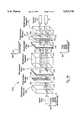
- FIG. 2a and FIG. 2bare schematic diagrams illustrating the two control states of a double-stage wavelength router 999.
- the wavelength router 999is under binary control from a control bit and hence has two control states.
- the router 999serves to separate channels of the wavelength spectrum applied to an input port 11 and determines which of two output ports 13, 14 are coupled to each of the channels.
- each of the subsetsmay comprise more than one channel and may itself be a WDM signal although having a smaller bandwidth than the original WDM signal 500.
- Each of the optical pathsis further labeled with either a horizontal double-headed line indicating horizontal polarization, or a vertical double-headed line indicating vertical polarization, or both horizontal and vertical double-headed lines indicating mixed horizontal and vertical polarizations in the optical signal at that point.
- the WDM signal 500enters the first birefringent element 30 that spatially separates horizontal and vertically polarized components of the WDM signal 500.
- the first birefringent element 30consists of a material that allows the vertically polarized portion of the optical signal to pass through without changing course because they are ordinary waves in the birefringent element 30. In contrast, horizontally polarized waves are redirected at an angle because of the birefringent walk-off effect. The angle of redirection is a well-known function of the particular materials chosen. Examples of materials suitable for construction of the birefringent element include calcite, rutile, lithium niobate, YVO 4 -based crystals, and the like.
- the horizontally polarized componenttravels along a path 101 as an extraordinary signal in the first birefringent element 30 while the vertically polarized component 102 travels as an ordinary signal and passes through without spatial reorientation.
- the resulting signals 101 and 102both carry the full frequency spectrum of the WDM signal 500.
- Both the horizontally and vertically polarized components 101 and 102are coupled to a switchable polarization rotator 40 under control of a control bit.
- the polarization rotator 40consists of two sub-element rotators that form a complementary state, i.e. when one turns on the other turns off.
- the rotator 40selectively rotates the polarization state of either signal 101 or 102 by a predefined amount. In the preferred embodiment, the rotator 40 rotates the signals by either 0° (i.e., no rotation) or 90°.
- the polarization rotator 40can be a twisted nematic liquid crystal rotator, ferroelectric liquid crystal rotator, pi-cell based liquid crystal rotator, magneto-optic based Faraday rotator, acousto-optic or electro-optic based polarization rotator.
- Commercially available rotators based on liquid crystal technologyare preferred, although other rotator technologies may be applied to meet the needs of a particular application.
- the switching speed of these elementsranges from a few milliseconds to nanoseconds, and therefore can be applied to a wide variety of systems to meet the needs of a particular application.
- FIG. 2aillustrates the control state in which the signal 102 is rotated by 90 degrees so that both signals 103, 104 exiting the rotator 40 have a horizontal polarization.
- FIG. 2billustrates the second control state in which the polarization of the signal 101 is rotated by 90° so that both optical signals 103, 104 exiting the rotator 40 have a vertical polarization.
- both the horizontal and vertical componentscontain the entire frequency spectrum of channels in the WDM signal 500.
- the stacked waveplates element 61is a stacked plurality of birefringent waveplates at selected orientations that generate two eigen states.
- the first eigen statecarries a first sub-spectrum with the same polarization as the input
- the second eigen statecarries a complementary sub-spectrum at the orthogonal polarization.
- the polarization of the incoming beam and the two output polarizationsform a pair of spectral responses, where (H, H) and (V, V) carry the first part of the input spectrum and (H, V) and (V, H) carry the complementary (second) part of the input spectrum, where V and H are vertical and horizontal polarization, respectively.
- FIGS. 2a and 2bThis may be better understood by comparing FIGS. 2a and 2b.
- horizontal polarizations 103, 104 input to the stacked waveplates element 61 as shown in FIG. 2aorthogonal vertical and horizontal polarizations are generated with the first spectral band residing in horizontal polarization and the second spectral band residing in vertical polarization.
- vertical polarizations 103, 104 input to the stacked waveplates element 61 as shown in FIG. 2borthogonal vertical and horizontal polarizations are generated with the first spectral band residing in vertical polarization and the second spectral band residing in horizontal polarization.
- the stacked waveplates element 61has a comb filter response curve with a substantially flat top or square wave spectral response.
- the stacked waveplates element 61has an asymmetric filter response.
- the pairs of optical responses 105, 106 output by the stacked waveplates element 61are coupled to a second birefringent element 50.
- This birefringent element 50has a similar construction to the first birefringent element 30 and spatially separates the horizontally and vertically polarized components of the input optical signals 105 and 106.
- the optical signals 105, 106are broken into vertically polarized components 107, 108 containing the second spectral band and horizontally polarized components 109, 110 containing the first spectral band.
- the two orthogonal polarizations that carry first spectral band 109, 110 in horizontal polarization and second set spectral band 107, 108 in vertical polarizationare separated by the second birefringent element 50.
- the second stacked waveplates element 62has substantially the same composition as the first stacked waveplates element 61.
- the horizontally polarized beams 109, 110 input to the second stacked waveplates element 62are further purified and maintain their polarization when they exit the second stacked waveplates element 62.
- the vertically polarized beams 107, 108experience a 90° polarization rotation and are also purified when they exit the second stacked waveplates element 62.
- the 90° polarization rotationis due to the fact that the vertically polarized beams 107, 108 carry the second spectral band and therefore are in the complementary state of element 62.
- all four beams 111, 112 and 113, 114have horizontal polarization.
- the spectral bands defined by the filter characteristics of the stacked waveplates elements 61, 62are separated with the second spectral band 501 on top and the first spectral band 502 below.
- a second polarization rotator 41 and a second birefringent element 70are used.
- the second rotator 41has two sub-elements that intercept the four parallel beams 111-114.
- the two sub-elements of the second rotator 41are set at a complementary state to the first rotator 40, i.e. when the first rotator 40 is turned on/off, the second rotator 41 is turned off/on.
- the polarization of beams 111 and 113is rotated by 90 degrees, and beams 112 and 114 are passed without change of polarization.
- FIG. 2bshows the other control state in which the two polarization rotators 40 and 41 have switched to their complimentary states, i.e. from on to off, or off to on, in contrast to their states shown in FIG. 2a.
- the full spectrum 500is first divided by polarization into two orthogonal states, i.e. vertical and horizontal polarization as indicated at 101 and 102, by the first birefringent element 30.
- the first polarization rotator 40is now set to have the output polarizations 103 and 104 both vertical.
- two orthogonal polarizationsi.e., horizontal and vertical
- carry second and first spectral bandsare generated, respectively.
- horizontal polarizationis used to carry the second spectral band
- vertical polarizationis used to carry the first spectral band of the WDM spectrum 500.
- the two spectral bandsare then spatially separated by the second birefringent element 50 with vertical polarization 107, 108 going upward and horizontal polarization 109, 110 passing through without deviation. This, therefore, separates the two spectral bands according to their polarizations.
- the resulting four beams 107-110enter the second stacked waveplates element 62 for further spectral purification.
- element 62Another important role of element 62 is its polarization rotation for the second spectral band.
- the stacked waveplates elements 61, 62have two eigen states.
- the vertically polarized beams 107, 108remain unchanged by element 62.
- the horizontally polarized beams 109 and 110are rotated by 90° as they pass through element 62 because they are in the complementary state of the stacked waveplate 62.
- a second polarization rotator 41 and third birefringent element 70are used, as previously discussed.
- the second rotator 41is set to rotate the polarizations of beams 112 and 114 by 90 degrees and to pass beams 111 and 112 without rotation.
- the resulting beams 115-118are recombined by the third birefringent element 70 and exit to ports 14 and 13 for the first and second spectral bands, respectively.
- FIGS. 3a and 3bA simplified version of the double stage wavelength router using a single stage switchable wavelength router is shown in FIGS. 3a and 3b, for the two states of operation. Two changes have been made with this structure in contrast to the double stage design shown in FIGS. 2a and 2b.
- the second stacked waveplates element 62 in FIGS. 2a and 2bhas been removed and the second polarization rotator 41 has been replaced with a passive polarization rotator with two sub-elements to intercept the beams 108 and 109, as shown in FIGS. 3a and 3b.
- the single stage wavelength routeroperates in substantially the same manner as the double stage router until the beams 107-110 exit the second birefringent element 50.
- the divided first and second spectral bandsare carried by two sets of orthogonally polarized beams 107, 108 and 109, 110, respectively.
- the positions of the first and second spectral bandsdepend on the polarization state of the beams 103 and 104. If the first spectral band is horizontally polarized by the first rotator 40, it will exit at the lower output port 13 and the second spectral band will exit at the upper output port 14.
- the first spectral bandis vertically polarized by the first rotator 40, it will exit at the upper output port 14 and the second spectral band will exit at the lower output port 13. Because of the birefringent walk-off effect in the second birefringent element 50, the vertically polarized light beams 107, 108 deviate from their original paths and travel upward, whereas the horizontally polarized beams 109, 110 pass through element 50 without changing their directions. The two pairs of beams 107, 108 and 109, 110 exiting the second birefringent element 50 have the same polarization but different frequencies.
- the passive polarization rotator 41is patterned to rotate polarization only in the areas that intercept beams 108 and 109. Therefore, at the output of the rotator 41, orthogonally polarized pairs of beams 115, 116 and 117, 118 are produced for both the first and second spectral bands. These beams 115-118 are then recombined by the third birefringent element 70 and exit to ports 13 and 14.
- the single-stage switchable wavelength routerhas the advantages of requiring fewer components as compared to the double-stage router. However, its spectral purity is not as good as the double stage router. It will depend on the applications and requirements of a specific WDM network, whether the single stage or the double stage wavelength router is preferred.
- One advantage of the present inventionis that routing is accomplished while conserving substantially all optical energy available in the WDM signal 500. That is to say, regardless of the polarization of the signals in WDM signal 500 both the horizontal and vertically polarized components are used and recombined at output ports 13, 14 resulting in very low loss through router 999.
- Each set of birefringent waveplates 61, 62is oriented at an unique optic axis angle with respect to the optical axis of polarization rotator 40.
- the spectral design for the stacked waveplates elements 61 and 62is dependent on the applications required by the WDM network. In the following, we list three different designs that can be used with current WDM systems. The first example uses stacked waveplates with equally separated sub-spectra centered at 1533 and 1557 nm wavelength. In the second case, asymmetric sub-spectra are produced by the stacked waveplates. This design can be used for an add/drop optical filter application. The third one is designed to cover the two transmission windows of fiber optics networks at 1310 and 1550 nm wavelengths. In this case, the center wavelengths of 1310 and 1550 nm can be interchangeably routed to either output port.
- FIG. 5shows an asymmetric spectrum design, where one output port carries a much narrower spectral width compared to the other port.
- This designcan be applied to a WDM network when there is a need to add or drop part of the optical channels at an optical exchange node.
- the add/drop filtercan be either passive or active, depending on system design and requirements.
- the switching elementi.e. the switchable polarization rotator arrays, can be replaced by two passive half-wave plates at each corresponding position of the polarization rotator, such that one of the ports is always designated as the add/drop port.
- the rest of the optical channelspass through the wavelength router and continue to propagate along the WDM network.
- the present inventioncan be further extended to farther apart spectra to cover two operational wavelength windows centered at 1310 and 1550 nm for fiber optic communications.
- Several techniquese.g., fiber fusion and multi-layer coating techniques
- the current designprovides lower crosstalk and a switchable characteristic, which are valuable from the system's point of view.
- FIGS. 2a-3b and discussed abovedemonstrate several embodiments of a single-stage 1 ⁇ 2 wavelength routing switch using birefringent elements for polarization-dependent routing of the beam.
- This conceptcan be extended to multiple stages to create 1 ⁇ 2 N wavelength routing switches. Multiple stages essentially result in a tree architecture. In those cases, each of the stages redirects a predetermined WDM channel or set of WDM channels in the optical signal along either of two alternative optical paths. As the signal propagates through the switch, N stages result in 2 N possible output ports.
- the following examples of 1 ⁇ N switches (where N is an arbitrary number) shown in FIGS. 7 through 11illustrate wavelength routing switches using polarized beamsplitters (PBS) in place of birefringent elements as polarization-independent routing elements.
- PBSpolarized beamsplitters
- a polarized beamsplitterpermits light of a predetermined polarization to pass directly through the beamsplitter, but orthogonally-polarized light is reflected or refracted within the beamsplitter and exits along a separate optical path. This is typically 90 degrees from the first beam, as shown in FIGS. 7-10.
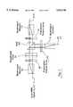
- FIG. 7is a simplified schematic diagram illustrating an alternative embodiment of a single-stage 1 ⁇ 2 wavelength routing switch using a polarized beamsplitter 80 as the polarization-dependent routing element in place of the second birefringent element 50 in FIGS. 3a and 3b.
- Two separate polarization rotator arrays 41 and 42are employed in place of the four-pixel polarization rotator array 41 in FIGS. 3a and 3b.
- FIG. 8is a simplified schematic diagram of an alternative embodiment of a wavelength routing switch using a polarized beamsplitter 80.
- Two additional wavelength filters 62 and 63provide additional spectral purification of the output beams, similar to the second wavelength filter 62 in FIGS. 2a and 2b.
- FIG. 9is a simplified schematic diagram of a 2 ⁇ 2 wavelength routing switch using a polarized beamsplitter 80. This can be considered as two 1 ⁇ 2 wavelength routing switches, as shown in FIG. 8, sharing a common PBS 80.
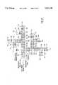
- FIG. 10is a simplified schematic diagram of a 1 ⁇ 8 wavelength routing switch using a network of 1 ⁇ 2 wavelength routing switches.
- Each 1 ⁇ 2 wavelength routing switchconsists of the comb nation of a polarization rotator 40, 91-96; a wavelength filter 61-67; and a PBS 80-86.
- the polarization rotator 40, 91-96rotates the polarization of the input beam pair in accordance with the control state of the device.
- the first PBS 80routes a predetermined first spectral band determined by the first wavelength filter 61 to either output ports ⁇ 1 - ⁇ 4 or ⁇ 5 - ⁇ 8 , based on the control state of the two pixels in the first polarization rotator array 40.
- a second complementary spectral bandis routed to the remaining four output ports.
- input WDM beamconsists of eight channels.
- the first spectral bandconsists of four WDM channels and the second spectral band consists of the remaining four WDM channels.
- the second 1 ⁇ 2 wavelength routing swichconsists of a second polarizer 91 that returns both beams to the same polarization.
- the second PBS 84routes a predetermined spectral band (e.g., two WDM channels) determined by the second wavelength filter 63 to either output ports ⁇ 5 - ⁇ 6 or ⁇ 7 - ⁇ 8 .
- the complementary spectral bandi.e., the remaining two WDM channels is routing to the remaining two output ports. This process is repeated by the remaining 1 ⁇ 2 wavelength switches so that one WDM channel is routed to each of the eight output ports ⁇ 1 - ⁇ 8 based on the control state of the initial polarization rotator array 40 and subsequent polarizers 91-96.
- Each output portincludes a double-pixel polarization rotator array 41-48 and polarization-dependent routing element 71-78 (e.g., a birefringent element).
- polarization-dependent routing element 71-78e.g., a birefringent element.
- the final polarization rotator array 41-48returns the beam pair to orthogonal polarizations so that they can be combined by the final birefringent element 71-78.
- FIG. 11is a simplified schematic diagram of a 1 ⁇ 8 wavelength routing switch using a network of 1 ⁇ 2 wavelength routing switches based on angled polarization separators 80-86.
- This type of polarization separatorprovides an offset angle at the output for vertical and horizontal polarizations.
- An angled polarization separatorcan be regarded as a compromise between the properties of a birefringent element (i.e., parallel beam output, high extinction ratio) and a PBS (perpendicular beam outputs, low extinction ratio). It provides a high polarization contrast ratio and also separates the output beams at an angle.
Landscapes
- Physics & Mathematics (AREA)
- General Physics & Mathematics (AREA)
- Optics & Photonics (AREA)
- Engineering & Computer Science (AREA)
- Computer Networks & Wireless Communication (AREA)
- Nonlinear Science (AREA)
- Optical Communication System (AREA)
- Optical Modulation, Optical Deflection, Nonlinear Optics, Optical Demodulation, Optical Logic Elements (AREA)
Abstract
Description
Claims (16)
Priority Applications (1)
| Application Number | Priority Date | Filing Date | Title |
|---|---|---|---|
| US08/982,978US5912748A (en) | 1996-07-23 | 1997-12-02 | Switchable wavelength router |
Applications Claiming Priority (4)
| Application Number | Priority Date | Filing Date | Title |
|---|---|---|---|
| US08/685,150US5724165A (en) | 1996-07-23 | 1996-07-23 | Fault-tolerant optical routing switch |
| US08/739,424US5867291A (en) | 1996-10-29 | 1996-10-29 | Programmable wavelength router |
| US08/780,291US5694233A (en) | 1996-07-23 | 1997-01-08 | Switchable wavelength router |
| US08/982,978US5912748A (en) | 1996-07-23 | 1997-12-02 | Switchable wavelength router |
Related Parent Applications (2)
| Application Number | Title | Priority Date | Filing Date |
|---|---|---|---|
| US08/739,424Continuation-In-PartUS5867291A (en) | 1996-07-23 | 1996-10-29 | Programmable wavelength router |
| US08/780,291Continuation-In-PartUS5694233A (en) | 1996-07-23 | 1997-01-08 | Switchable wavelength router |
Publications (1)
| Publication Number | Publication Date |
|---|---|
| US5912748Atrue US5912748A (en) | 1999-06-15 |
Family
ID=46253859
Family Applications (1)
| Application Number | Title | Priority Date | Filing Date |
|---|---|---|---|
| US08/982,978Expired - Fee RelatedUS5912748A (en) | 1996-07-23 | 1997-12-02 | Switchable wavelength router |
Country Status (1)
| Country | Link |
|---|---|
| US (1) | US5912748A (en) |
Cited By (81)
| Publication number | Priority date | Publication date | Assignee | Title |
|---|---|---|---|---|
| WO2000057589A1 (en)* | 1999-03-22 | 2000-09-28 | Chorum Technologies Lp | Method and apparatus for wavelenght multiplexing/demultiplexing |
| US6175432B1 (en)* | 1996-07-23 | 2001-01-16 | Chorum Technologies Inc. | Multi-wavelength cross-connect optical network |
| US6208442B1 (en) | 1998-03-26 | 2001-03-27 | Chorum Technologies, Inc. | Programmable optical multiplexer |
| US6212313B1 (en)* | 2000-01-31 | 2001-04-03 | Oplink Communications, Inc. | Optical interleaver |
| US6236506B1 (en) | 1999-09-23 | 2001-05-22 | Avanex Corporation | Reflection-type optical circulation utilizing a lens and birefringent plates |
| US6252711B1 (en)* | 2000-03-21 | 2001-06-26 | Lucent Technologies, Inc | Polarization diversity for birefingent filters |
| WO2001047163A1 (en)* | 1999-12-20 | 2001-06-28 | Chorum Technologies L.P. | Dispersion compensation for optical systems |
| US6285478B1 (en) | 1998-03-26 | 2001-09-04 | Chorum Technologies Lp | Programmable optical add/drop device |
| US6288807B1 (en)* | 1996-10-29 | 2001-09-11 | Chorum Technologies Lp | Optical wavelength router |
| US6301046B1 (en)* | 1999-12-31 | 2001-10-09 | Jds Uniphase Corporation | Interleaver/deinterleavers causing little or no dispersion of optical signals |
| US6335830B1 (en)* | 1999-12-31 | 2002-01-01 | Jds Uniphase Corporation | Double-pass folded interleaver/deinterleavers |
| US6337934B1 (en) | 1998-08-27 | 2002-01-08 | Chorum Technologies, Inc. | NxN switch array with polarization displacer |
| US6353467B1 (en) | 1998-01-06 | 2002-03-05 | Chorum Technologies Inc. | Acute twist nematic (ATN) liquid crystal device for optical communication applications |
| WO2002027370A1 (en)* | 2000-06-30 | 2002-04-04 | Nortel Networks (Photonics) Pty Ltd | Optical filter for frequency dependent filtering |
| US6373607B1 (en)* | 1998-05-22 | 2002-04-16 | Trex Communications Corporation | Liquid crystal variable retarder for free-space laser communication system |
| WO2002011299A3 (en)* | 2000-07-28 | 2002-04-25 | Arroyo Optics Inc | Interleaver filters employing non-birefringent elements |
| US6404536B1 (en)* | 2000-12-30 | 2002-06-11 | Industrial Technology Research Institute | Polarization independent tunable acousto-optical filter and the method of the same |
| US6407846B1 (en) | 2001-03-16 | 2002-06-18 | All Optical Networks, Inc. | Photonic wavelength shifting method |
| US20020089723A1 (en)* | 2000-11-22 | 2002-07-11 | Patel Jayantilal S. | Polarization encoder device |
| US6421177B1 (en) | 2000-03-03 | 2002-07-16 | Arroyo Optics, Inc. | Interleaving optical filter |
| WO2002056521A1 (en)* | 2000-11-03 | 2002-07-18 | Network Photonics, Inc. | Reduction of polarization-dependent loss from grating used in double-pass configuration |
| US6427033B1 (en) | 2000-10-02 | 2002-07-30 | John N. Hait | Photonic image router |
| US6441944B1 (en)* | 1997-12-09 | 2002-08-27 | Samsung Electronics Co., Ltd. | Optical attenuator using isolator and optical communications system including the same |
| US20020118411A1 (en)* | 2001-02-27 | 2002-08-29 | Cooney Thomas F. | Full-duplex optical add/drop communications system utilizing central light sources |
| US6452702B1 (en)* | 1997-04-02 | 2002-09-17 | Chorum Technologies Lp | N×M digitally programmable optical routing switch |
| US20020131125A1 (en)* | 2001-03-16 | 2002-09-19 | Myers Michael H. | Replicated-spectrum photonic transceiving |
| US20020131100A1 (en)* | 2001-03-16 | 2002-09-19 | Myers Michael H. | Method for photonic wavelength error detection |
| US6459827B1 (en) | 2000-10-02 | 2002-10-01 | John N. Hait | Polarization-stabilizing, phase-and-polarization-insensitive, photonic data router |
| US6459487B1 (en) | 2000-09-05 | 2002-10-01 | Gang Paul Chen | System and method for fabricating components of precise optical path length |
| US6463189B1 (en) | 2000-02-24 | 2002-10-08 | Avanex Corporation | Method and apparatus for optical switching devices utilizing a bi-morphic piezoelectric apparatus |
| US6466704B1 (en) | 2000-09-13 | 2002-10-15 | Nortel Networks (Photonics) Pty Ltd. | Optical filtering method and device |
| US6476967B2 (en)* | 2001-03-27 | 2002-11-05 | Industrial Technology Research Institute | Compact optical circulator with three ports |
| US6477287B1 (en) | 2000-10-02 | 2002-11-05 | John N. Hait | Polarization-preserving, phase-and-polarization-insensitive, photonic data router |
| US6493139B1 (en)* | 2001-03-16 | 2002-12-10 | Hongdu Liu | Optical switch |
| US6498680B1 (en) | 1996-10-29 | 2002-12-24 | Chorum Technologies Lp | Compact tunable optical wavelength interleaver |
| US20020196496A1 (en)* | 2000-11-03 | 2002-12-26 | Network Photonics, Inc. | Reduction of polarization-dependent loss in double-pass grating configurations |
| US6504642B1 (en) | 1999-09-15 | 2003-01-07 | Spectraswitch, Inc. | Birefringent optical device |
| US6519022B1 (en)* | 1997-04-02 | 2003-02-11 | Chorum Technologies Lp | Optical routing switch using symmetric liquid crystal cells |
| US6519060B1 (en)* | 1999-06-04 | 2003-02-11 | Chorum Technologies Lp | Synchronous optical network in frequency domain |
| US20030035605A1 (en)* | 2000-02-17 | 2003-02-20 | Oleg Bouevitch | Double pass arrangement for a liquid crystal device |
| US6529326B2 (en) | 2001-06-13 | 2003-03-04 | Jds Uniphase Corporation | Tunable optical filter |
| US6545783B1 (en)* | 1996-10-29 | 2003-04-08 | Chorum Technologies Lp | Optical wavelength add/drop multiplexer |
| US6560015B1 (en) | 1999-09-23 | 2003-05-06 | Avanex Corporation | High-isolation dense wavelength division multiplexer utilizing birefringent plates and a non-linear interferometer |
| US6559992B2 (en) | 2000-03-27 | 2003-05-06 | Chorum Technologies Lp | Adjustable chromatic dispersion compensation |
| US20030090762A1 (en)* | 2001-09-28 | 2003-05-15 | Mcguire James P. | Littrow grating based oadm |
| US20030113055A1 (en)* | 2001-12-18 | 2003-06-19 | Jing Zhao | Solid-state optical wavelength switches |
| US6600582B1 (en) | 1997-03-24 | 2003-07-29 | Chorum Technologies Lp | Optical add/drop wavelength switch |
| US6614573B1 (en) | 2001-01-30 | 2003-09-02 | Avanex Corporation | Switchable interleaved channel separator devices and systems |
| US20030170025A1 (en)* | 2002-03-08 | 2003-09-11 | Network Photonics, Inc. | Optical wavelength cross connect architectures using wavelength routing elements |
| US20030215179A1 (en)* | 2001-03-30 | 2003-11-20 | Mcguire James P. | Programmable optical add/drop multiplexer |
| US6680470B1 (en) | 2001-11-14 | 2004-01-20 | Dicon Fiberoptics, Inc. | Interleaver with thermal and chromatic dispersion compensation |
| EP1139146A3 (en)* | 2000-03-21 | 2004-02-04 | Lucent Technologies Inc. | Double-pass polarization diversified birefringent filter |
| US20040033010A1 (en)* | 2002-06-12 | 2004-02-19 | Mcguire James P. | Wavelength selective optical switch |
| US6707550B1 (en) | 2000-04-18 | 2004-03-16 | Pts Corporation | Wavelength monitor for WDM systems |
| US6735016B1 (en) | 1999-09-15 | 2004-05-11 | Spectraswitch, Inc. | Electro-optically controllable polarization insensitive optical device |
| US20040136718A1 (en)* | 2002-07-23 | 2004-07-15 | Mcguire James P. | East-West separable ROADM |
| US20040247312A1 (en)* | 2001-12-03 | 2004-12-09 | Fujitsu Limited | Optical communication system |
| US20040247227A1 (en)* | 2001-10-25 | 2004-12-09 | Haim Eder | Polarization insensitive tunable optical filters |
| US6847786B2 (en) | 1996-10-29 | 2005-01-25 | Ec-Optics Technology, Inc. | Compact wavelength filter using optical birefringence and reflective elements |
| US6850655B2 (en)* | 1997-06-16 | 2005-02-01 | Novera Optics, Inc. | Optical apparatus with faraday rotator, static gain flattening filter and variable optical attenuator |
| US6853488B1 (en) | 1999-09-23 | 2005-02-08 | Avanex Corporation | Reflection-type optical circulator utilizing a lens and birefringent plates |
| US20050111785A1 (en)* | 2003-10-09 | 2005-05-26 | Jing Zhao | Multi-port optical switches |
| US6907167B2 (en) | 2001-01-19 | 2005-06-14 | Gazillion Bits, Inc. | Optical interleaving with enhanced spectral response and reduced polarization sensitivity |
| US20050165667A1 (en)* | 2004-01-27 | 2005-07-28 | Cox George C. | System and method for customer video authentication to prevent identity theft |
| US7202996B2 (en)* | 2001-08-16 | 2007-04-10 | Telefonaktiebolaget Lm Ericsson (Publ) | Optical amplifier |
| US20080252961A1 (en)* | 2007-04-13 | 2008-10-16 | Fujitsu Limited | Optical transceiver |
| US20080310848A1 (en)* | 2007-06-15 | 2008-12-18 | Hitachi Cable, Ltd. | Combined optical and electrical transmission assembly and module |
| WO2008047245A3 (en)* | 2006-10-20 | 2009-04-23 | Crystalith Ltd | Optical devices based on internal conical diffraction |
| WO2010060036A1 (en)* | 2008-11-24 | 2010-05-27 | Oclaro (North America), Inc. | Method and apparatus for spectral band management |
| EP1520193A4 (en)* | 2001-02-14 | 2011-07-27 | Finisar Corp | Method and apparatus for an optical filter |
| US10439302B2 (en) | 2017-06-08 | 2019-10-08 | Pct International, Inc. | Connecting device for connecting and grounding coaxial cable connectors |
| US10447004B2 (en) | 2015-11-19 | 2019-10-15 | Nlight, Inc. | Laser fault tolerance and self-calibration system |
| US10574020B2 (en) | 2016-12-15 | 2020-02-25 | Nlight, Inc. | Fiber laser packaging |
| CN111194528A (en)* | 2017-10-05 | 2020-05-22 | 华为技术有限公司 | Wavelength monitoring and/or control apparatus, laser system comprising the apparatus and method of operating the apparatus |
| US10784645B2 (en) | 2018-03-12 | 2020-09-22 | Nlight, Inc. | Fiber laser having variably wound optical fiber |
| US11025034B2 (en) | 2016-08-31 | 2021-06-01 | Nlight, Inc. | Laser cooling system |
| US11159245B2 (en) | 2019-07-03 | 2021-10-26 | Raytheon Company | Methods and apparatus for cavity angle tuning for operating condition optimization |
| US11290191B2 (en) | 2019-06-20 | 2022-03-29 | Raytheon Company | Methods and apparatus for tracking moving objects using symmetric phase change detection |
| US11307395B2 (en) | 2019-05-23 | 2022-04-19 | Raytheon Company | Methods and apparatus for optical path length equalization in an optical cavity |
| US11353774B2 (en) | 2019-07-15 | 2022-06-07 | Raytheon Company | Methods and apparatus for cavity length tuning for operating point optimization |
| US20220182147A1 (en)* | 2020-12-04 | 2022-06-09 | Raytheon Company | Method for fully-networkable single aperture free-space optical transceiver |
Citations (11)
| Publication number | Priority date | Publication date | Assignee | Title |
|---|---|---|---|---|
| US4650289A (en)* | 1979-02-21 | 1987-03-17 | Fujitsu Limited | Optical circulator |
| US4720171A (en)* | 1985-11-05 | 1988-01-19 | Itt Defense Communications, A Division Of Itt Corporation | Liquid crystal optical switching device having reduced crosstalk |
| US4989941A (en)* | 1988-03-18 | 1991-02-05 | The United States Of America As Represented By The Secretary Of The Air Force | Normal incidence optical switches using ferroelectric liquid crystals |
| US5013140A (en)* | 1987-09-11 | 1991-05-07 | British Telecommunications Public Limited Company | Optical space switch |
| US5162944A (en)* | 1989-12-28 | 1992-11-10 | Fujitsu Limited | Optical space switch and network for such optical space switches |
| US5165104A (en)* | 1991-03-01 | 1992-11-17 | Optivideo Corporation | Optical interconnecting device and method |
| US5317658A (en)* | 1992-04-06 | 1994-05-31 | At&T Bell Laboratories | Apparatus and method for providing a polarization independent optical switch |
| US5381250A (en)* | 1992-11-06 | 1995-01-10 | Displaytech, Inc. | Electro-optical switch with 4 port modules with electro-optic polarization rotators |
| US5526153A (en)* | 1994-01-21 | 1996-06-11 | At&T Corp. | Optical channel adding/dropping filter |
| US5694233A (en)* | 1996-07-23 | 1997-12-02 | Macro-Vision Communications, Llc | Switchable wavelength router |
| US5724165A (en)* | 1996-07-23 | 1998-03-03 | Macro-Vision Communications, L.L.C. | Fault-tolerant optical routing switch |
- 1997
- 1997-12-02USUS08/982,978patent/US5912748A/ennot_activeExpired - Fee Related
Patent Citations (11)
| Publication number | Priority date | Publication date | Assignee | Title |
|---|---|---|---|---|
| US4650289A (en)* | 1979-02-21 | 1987-03-17 | Fujitsu Limited | Optical circulator |
| US4720171A (en)* | 1985-11-05 | 1988-01-19 | Itt Defense Communications, A Division Of Itt Corporation | Liquid crystal optical switching device having reduced crosstalk |
| US5013140A (en)* | 1987-09-11 | 1991-05-07 | British Telecommunications Public Limited Company | Optical space switch |
| US4989941A (en)* | 1988-03-18 | 1991-02-05 | The United States Of America As Represented By The Secretary Of The Air Force | Normal incidence optical switches using ferroelectric liquid crystals |
| US5162944A (en)* | 1989-12-28 | 1992-11-10 | Fujitsu Limited | Optical space switch and network for such optical space switches |
| US5165104A (en)* | 1991-03-01 | 1992-11-17 | Optivideo Corporation | Optical interconnecting device and method |
| US5317658A (en)* | 1992-04-06 | 1994-05-31 | At&T Bell Laboratories | Apparatus and method for providing a polarization independent optical switch |
| US5381250A (en)* | 1992-11-06 | 1995-01-10 | Displaytech, Inc. | Electro-optical switch with 4 port modules with electro-optic polarization rotators |
| US5526153A (en)* | 1994-01-21 | 1996-06-11 | At&T Corp. | Optical channel adding/dropping filter |
| US5694233A (en)* | 1996-07-23 | 1997-12-02 | Macro-Vision Communications, Llc | Switchable wavelength router |
| US5724165A (en)* | 1996-07-23 | 1998-03-03 | Macro-Vision Communications, L.L.C. | Fault-tolerant optical routing switch |
Cited By (116)
| Publication number | Priority date | Publication date | Assignee | Title |
|---|---|---|---|---|
| US6175432B1 (en)* | 1996-07-23 | 2001-01-16 | Chorum Technologies Inc. | Multi-wavelength cross-connect optical network |
| US6498680B1 (en) | 1996-10-29 | 2002-12-24 | Chorum Technologies Lp | Compact tunable optical wavelength interleaver |
| US6288807B1 (en)* | 1996-10-29 | 2001-09-11 | Chorum Technologies Lp | Optical wavelength router |
| US6545783B1 (en)* | 1996-10-29 | 2003-04-08 | Chorum Technologies Lp | Optical wavelength add/drop multiplexer |
| US6847786B2 (en) | 1996-10-29 | 2005-01-25 | Ec-Optics Technology, Inc. | Compact wavelength filter using optical birefringence and reflective elements |
| US6163393A (en)* | 1996-10-29 | 2000-12-19 | Chorum Technologies Inc. | Method and apparatus for wavelength multipexing/demultiplexing |
| US6600582B1 (en) | 1997-03-24 | 2003-07-29 | Chorum Technologies Lp | Optical add/drop wavelength switch |
| US6519022B1 (en)* | 1997-04-02 | 2003-02-11 | Chorum Technologies Lp | Optical routing switch using symmetric liquid crystal cells |
| US6452702B1 (en)* | 1997-04-02 | 2002-09-17 | Chorum Technologies Lp | N×M digitally programmable optical routing switch |
| US6552833B2 (en) | 1997-04-15 | 2003-04-22 | Macro-Vision Communications, Inc. | Programmable optical add/drop multiplexer |
| US6850655B2 (en)* | 1997-06-16 | 2005-02-01 | Novera Optics, Inc. | Optical apparatus with faraday rotator, static gain flattening filter and variable optical attenuator |
| US6441944B1 (en)* | 1997-12-09 | 2002-08-27 | Samsung Electronics Co., Ltd. | Optical attenuator using isolator and optical communications system including the same |
| US6353467B1 (en) | 1998-01-06 | 2002-03-05 | Chorum Technologies Inc. | Acute twist nematic (ATN) liquid crystal device for optical communication applications |
| US6285478B1 (en) | 1998-03-26 | 2001-09-04 | Chorum Technologies Lp | Programmable optical add/drop device |
| US6208442B1 (en) | 1998-03-26 | 2001-03-27 | Chorum Technologies, Inc. | Programmable optical multiplexer |
| US6373607B1 (en)* | 1998-05-22 | 2002-04-16 | Trex Communications Corporation | Liquid crystal variable retarder for free-space laser communication system |
| US6337934B1 (en) | 1998-08-27 | 2002-01-08 | Chorum Technologies, Inc. | NxN switch array with polarization displacer |
| WO2000057589A1 (en)* | 1999-03-22 | 2000-09-28 | Chorum Technologies Lp | Method and apparatus for wavelenght multiplexing/demultiplexing |
| US6519060B1 (en)* | 1999-06-04 | 2003-02-11 | Chorum Technologies Lp | Synchronous optical network in frequency domain |
| US6735016B1 (en) | 1999-09-15 | 2004-05-11 | Spectraswitch, Inc. | Electro-optically controllable polarization insensitive optical device |
| US6594063B1 (en) | 1999-09-15 | 2003-07-15 | Spectraswitch, Inc. | Birefringent optical device |
| US6504642B1 (en) | 1999-09-15 | 2003-01-07 | Spectraswitch, Inc. | Birefringent optical device |
| US6236506B1 (en) | 1999-09-23 | 2001-05-22 | Avanex Corporation | Reflection-type optical circulation utilizing a lens and birefringent plates |
| US6853488B1 (en) | 1999-09-23 | 2005-02-08 | Avanex Corporation | Reflection-type optical circulator utilizing a lens and birefringent plates |
| US6560015B1 (en) | 1999-09-23 | 2003-05-06 | Avanex Corporation | High-isolation dense wavelength division multiplexer utilizing birefringent plates and a non-linear interferometer |
| US6396609B1 (en)* | 1999-12-20 | 2002-05-28 | Chorum Technologies, Lp | Dispersion compensation for optical systems |
| WO2001047163A1 (en)* | 1999-12-20 | 2001-06-28 | Chorum Technologies L.P. | Dispersion compensation for optical systems |
| US6301046B1 (en)* | 1999-12-31 | 2001-10-09 | Jds Uniphase Corporation | Interleaver/deinterleavers causing little or no dispersion of optical signals |
| US6335830B1 (en)* | 1999-12-31 | 2002-01-01 | Jds Uniphase Corporation | Double-pass folded interleaver/deinterleavers |
| US6212313B1 (en)* | 2000-01-31 | 2001-04-03 | Oplink Communications, Inc. | Optical interleaver |
| US6215923B1 (en)* | 2000-01-31 | 2001-04-10 | Oplink Communications, Inc. | Optical interleaver |
| US6859573B2 (en)* | 2000-02-17 | 2005-02-22 | Jds Uniphase Inc. | Double pass arrangement for a liquid crystal device |
| US20030035605A1 (en)* | 2000-02-17 | 2003-02-20 | Oleg Bouevitch | Double pass arrangement for a liquid crystal device |
| US6463189B1 (en) | 2000-02-24 | 2002-10-08 | Avanex Corporation | Method and apparatus for optical switching devices utilizing a bi-morphic piezoelectric apparatus |
| US6650801B1 (en) | 2000-02-24 | 2003-11-18 | Avanex Corporation | Reversible optical circulator utilizing a bi-morphic piezoelectric apparatus |
| US6421177B1 (en) | 2000-03-03 | 2002-07-16 | Arroyo Optics, Inc. | Interleaving optical filter |
| US6252711B1 (en)* | 2000-03-21 | 2001-06-26 | Lucent Technologies, Inc | Polarization diversity for birefingent filters |
| EP1139147A3 (en)* | 2000-03-21 | 2004-05-19 | Lucent Technologies Inc. | Polarization diversity for birefringent filters |
| EP1139146A3 (en)* | 2000-03-21 | 2004-02-04 | Lucent Technologies Inc. | Double-pass polarization diversified birefringent filter |
| US6559992B2 (en) | 2000-03-27 | 2003-05-06 | Chorum Technologies Lp | Adjustable chromatic dispersion compensation |
| US6707550B1 (en) | 2000-04-18 | 2004-03-16 | Pts Corporation | Wavelength monitor for WDM systems |
| WO2002027370A1 (en)* | 2000-06-30 | 2002-04-04 | Nortel Networks (Photonics) Pty Ltd | Optical filter for frequency dependent filtering |
| WO2002011299A3 (en)* | 2000-07-28 | 2002-04-25 | Arroyo Optics Inc | Interleaver filters employing non-birefringent elements |
| US6459487B1 (en) | 2000-09-05 | 2002-10-01 | Gang Paul Chen | System and method for fabricating components of precise optical path length |
| US6466704B1 (en) | 2000-09-13 | 2002-10-15 | Nortel Networks (Photonics) Pty Ltd. | Optical filtering method and device |
| US6427033B1 (en) | 2000-10-02 | 2002-07-30 | John N. Hait | Photonic image router |
| US6477287B1 (en) | 2000-10-02 | 2002-11-05 | John N. Hait | Polarization-preserving, phase-and-polarization-insensitive, photonic data router |
| US6459827B1 (en) | 2000-10-02 | 2002-10-01 | John N. Hait | Polarization-stabilizing, phase-and-polarization-insensitive, photonic data router |
| US20020196496A1 (en)* | 2000-11-03 | 2002-12-26 | Network Photonics, Inc. | Reduction of polarization-dependent loss in double-pass grating configurations |
| WO2002056521A1 (en)* | 2000-11-03 | 2002-07-18 | Network Photonics, Inc. | Reduction of polarization-dependent loss from grating used in double-pass configuration |
| US8457501B2 (en) | 2000-11-03 | 2013-06-04 | Altera Corporation | Reduction of polarization-dependent loss in double-pass grating configurations |
| US20020105697A1 (en)* | 2000-11-03 | 2002-08-08 | Network Photonics, Inc. | Reduction of polarization-dependent loss from grating used in double-pass configuration |
| US7054561B2 (en) | 2000-11-03 | 2006-05-30 | Pts Corporation | Reduction of polarization-dependent loss from grating used in double-pass configuration |
| US6751415B1 (en)* | 2000-11-03 | 2004-06-15 | Pts Corporation | Reduction of polarization-dependent loss from grating used in double-pass configuration |
| US20020089723A1 (en)* | 2000-11-22 | 2002-07-11 | Patel Jayantilal S. | Polarization encoder device |
| US7127179B2 (en)* | 2000-11-22 | 2006-10-24 | Optellios, Inc. | Polarization encoder device |
| US6404536B1 (en)* | 2000-12-30 | 2002-06-11 | Industrial Technology Research Institute | Polarization independent tunable acousto-optical filter and the method of the same |
| US6907167B2 (en) | 2001-01-19 | 2005-06-14 | Gazillion Bits, Inc. | Optical interleaving with enhanced spectral response and reduced polarization sensitivity |
| US6614573B1 (en) | 2001-01-30 | 2003-09-02 | Avanex Corporation | Switchable interleaved channel separator devices and systems |
| US6721078B1 (en) | 2001-01-30 | 2004-04-13 | Avanex Corporation | Switchable interleaved channel separator devices and systems |
| EP1520193A4 (en)* | 2001-02-14 | 2011-07-27 | Finisar Corp | Method and apparatus for an optical filter |
| US6885821B2 (en) | 2001-02-27 | 2005-04-26 | Avanex Corporation | Full-duplex optical add/drop communications system utilizing central light sources |
| US20020118411A1 (en)* | 2001-02-27 | 2002-08-29 | Cooney Thomas F. | Full-duplex optical add/drop communications system utilizing central light sources |
| US6493139B1 (en)* | 2001-03-16 | 2002-12-10 | Hongdu Liu | Optical switch |
| US20020131125A1 (en)* | 2001-03-16 | 2002-09-19 | Myers Michael H. | Replicated-spectrum photonic transceiving |
| US20020131100A1 (en)* | 2001-03-16 | 2002-09-19 | Myers Michael H. | Method for photonic wavelength error detection |
| US6407846B1 (en) | 2001-03-16 | 2002-06-18 | All Optical Networks, Inc. | Photonic wavelength shifting method |
| US6476967B2 (en)* | 2001-03-27 | 2002-11-05 | Industrial Technology Research Institute | Compact optical circulator with three ports |
| US7177493B2 (en) | 2001-03-30 | 2007-02-13 | Optical Research Associates | Programmable optical add/drop multiplexer |
| US20030215179A1 (en)* | 2001-03-30 | 2003-11-20 | Mcguire James P. | Programmable optical add/drop multiplexer |
| US6529326B2 (en) | 2001-06-13 | 2003-03-04 | Jds Uniphase Corporation | Tunable optical filter |
| US7202996B2 (en)* | 2001-08-16 | 2007-04-10 | Telefonaktiebolaget Lm Ericsson (Publ) | Optical amplifier |
| US7203421B2 (en) | 2001-09-28 | 2007-04-10 | Optical Research Associates | Littrow grating based OADM |
| US20030090762A1 (en)* | 2001-09-28 | 2003-05-15 | Mcguire James P. | Littrow grating based oadm |
| US20040247227A1 (en)* | 2001-10-25 | 2004-12-09 | Haim Eder | Polarization insensitive tunable optical filters |
| US7120333B2 (en)* | 2001-10-25 | 2006-10-10 | Lambda Crossing, Ltd. | Polarization insensitive tunable optical filters |
| US6680470B1 (en) | 2001-11-14 | 2004-01-20 | Dicon Fiberoptics, Inc. | Interleaver with thermal and chromatic dispersion compensation |
| US20040247312A1 (en)* | 2001-12-03 | 2004-12-09 | Fujitsu Limited | Optical communication system |
| US20030113055A1 (en)* | 2001-12-18 | 2003-06-19 | Jing Zhao | Solid-state optical wavelength switches |
| US6718082B2 (en) | 2001-12-18 | 2004-04-06 | Agiltron, Inc. | Solid-State optical wavelength switches |
| US20030170025A1 (en)* | 2002-03-08 | 2003-09-11 | Network Photonics, Inc. | Optical wavelength cross connect architectures using wavelength routing elements |
| US7079723B2 (en)* | 2002-03-08 | 2006-07-18 | Pts Corporation | Optical wavelength cross connect architectures using wavelength routing elements |
| US20060182387A1 (en)* | 2002-06-12 | 2006-08-17 | Mcguire James P Jr | Wavelength selective optical switch |
| US20040033010A1 (en)* | 2002-06-12 | 2004-02-19 | Mcguire James P. | Wavelength selective optical switch |
| US20070104418A1 (en)* | 2002-06-12 | 2007-05-10 | Mcguire James P Jr | Wavelength selective optical switch |
| US7330615B2 (en) | 2002-06-12 | 2008-02-12 | Optical Research Associates | Wavelength selective optical switch |
| US20080205821A1 (en)* | 2002-06-12 | 2008-08-28 | Optical Research Associates | Wavelength selective optical switch |
| US7058251B2 (en) | 2002-06-12 | 2006-06-06 | Optical Research Associates | Wavelength selective optical switch |
| US7519247B2 (en) | 2002-06-12 | 2009-04-14 | Optical Research Associates | Wavelength selective optical switch |
| US20040136718A1 (en)* | 2002-07-23 | 2004-07-15 | Mcguire James P. | East-West separable ROADM |
| US6941073B2 (en) | 2002-07-23 | 2005-09-06 | Optical Research Associates | East-west separable ROADM |
| US20050111785A1 (en)* | 2003-10-09 | 2005-05-26 | Jing Zhao | Multi-port optical switches |
| US7224860B2 (en) | 2003-10-09 | 2007-05-29 | Jing Zhao | Multi-port optical switches |
| US20050165667A1 (en)* | 2004-01-27 | 2005-07-28 | Cox George C. | System and method for customer video authentication to prevent identity theft |
| US20090168613A1 (en)* | 2006-10-20 | 2009-07-02 | Crystalith Ltd. | Optical devices based on internal conical diffraction |
| WO2008047245A3 (en)* | 2006-10-20 | 2009-04-23 | Crystalith Ltd | Optical devices based on internal conical diffraction |
| US8514685B2 (en)* | 2006-10-20 | 2013-08-20 | Bioaxial Sas | Optical devices based on internal conical diffraction |
| US20080252961A1 (en)* | 2007-04-13 | 2008-10-16 | Fujitsu Limited | Optical transceiver |
| US20080310848A1 (en)* | 2007-06-15 | 2008-12-18 | Hitachi Cable, Ltd. | Combined optical and electrical transmission assembly and module |
| US8452181B2 (en)* | 2007-06-15 | 2013-05-28 | Hitachi Cable, Ltd. | Combined optical and electrical transmission assembly and module |
| WO2010060036A1 (en)* | 2008-11-24 | 2010-05-27 | Oclaro (North America), Inc. | Method and apparatus for spectral band management |
| US10447004B2 (en) | 2015-11-19 | 2019-10-15 | Nlight, Inc. | Laser fault tolerance and self-calibration system |
| US11025034B2 (en) | 2016-08-31 | 2021-06-01 | Nlight, Inc. | Laser cooling system |
| US10574020B2 (en) | 2016-12-15 | 2020-02-25 | Nlight, Inc. | Fiber laser packaging |
| US10439302B2 (en) | 2017-06-08 | 2019-10-08 | Pct International, Inc. | Connecting device for connecting and grounding coaxial cable connectors |
| US10855003B2 (en) | 2017-06-08 | 2020-12-01 | Pct International, Inc. | Connecting device for connecting and grounding coaxial cable connectors |
| CN111194528A (en)* | 2017-10-05 | 2020-05-22 | 华为技术有限公司 | Wavelength monitoring and/or control apparatus, laser system comprising the apparatus and method of operating the apparatus |
| CN111194528B (en)* | 2017-10-05 | 2021-10-26 | 华为技术有限公司 | Wavelength monitoring and/or control device, laser system comprising said device and method of operating said device |
| US10784645B2 (en) | 2018-03-12 | 2020-09-22 | Nlight, Inc. | Fiber laser having variably wound optical fiber |
| US11307395B2 (en) | 2019-05-23 | 2022-04-19 | Raytheon Company | Methods and apparatus for optical path length equalization in an optical cavity |
| US11290191B2 (en) | 2019-06-20 | 2022-03-29 | Raytheon Company | Methods and apparatus for tracking moving objects using symmetric phase change detection |
| US11159245B2 (en) | 2019-07-03 | 2021-10-26 | Raytheon Company | Methods and apparatus for cavity angle tuning for operating condition optimization |
| US11353774B2 (en) | 2019-07-15 | 2022-06-07 | Raytheon Company | Methods and apparatus for cavity length tuning for operating point optimization |
| US20220182147A1 (en)* | 2020-12-04 | 2022-06-09 | Raytheon Company | Method for fully-networkable single aperture free-space optical transceiver |
| WO2022119687A1 (en)* | 2020-12-04 | 2022-06-09 | Raytheon Company | Method for fully-networkable single aperture free-space optical transceiver |
| US11595129B2 (en)* | 2020-12-04 | 2023-02-28 | Raytheon Company | Method for fully-networkable single aperture free-space optical transceiver |
Similar Documents
| Publication | Publication Date | Title |
|---|---|---|
| US5912748A (en) | Switchable wavelength router | |
| US5694233A (en) | Switchable wavelength router | |
| US6005697A (en) | Multi-wavelength cross-connect optical network | |
| US6600582B1 (en) | Optical add/drop wavelength switch | |
| US5978116A (en) | Programmable wavelength router | |
| US6097518A (en) | N x M optical wavelength routing switch | |
| US6847786B2 (en) | Compact wavelength filter using optical birefringence and reflective elements | |
| US6115155A (en) | System for dealing with faults in an optical link | |
| US6545783B1 (en) | Optical wavelength add/drop multiplexer | |
| WO1999008403A1 (en) | Multi-wavelength cross-connect optical network | |
| US6490377B1 (en) | Optical interleaver | |
| US20020051266A1 (en) | Programmable wavelength router | |
| MXPA99006253A (en) | Switchable wavelength router | |
| US6687462B1 (en) | Wavelength slicer for optical signal switching | |
| MXPA99003970A (en) | Programmable wavelength router |
Legal Events
| Date | Code | Title | Description |
|---|---|---|---|
| AS | Assignment | Owner name:MACRO-VISION COMMUNICATIONS INC., COLORADO Free format text:ASSIGNMENT OF ASSIGNORS INTEREST;ASSIGNORS:WU, KUANG-YI;LIU, JIAN-YU;REEL/FRAME:008900/0602 Effective date:19971201 | |
| AS | Assignment | Owner name:CHORUM TECHNOLOGIES INC., TEXAS Free format text:ASSIGNMENT OF ASSIGNORS INTEREST;ASSIGNOR:MACRO-VISION COMMUNICATIONS, INC.;REEL/FRAME:009281/0344 Effective date:19980624 | |
| AS | Assignment | Owner name:CHORUM TECHNOLOGIES, LP, TEXAS Free format text:CERTIFICATE OF CONVERSION;ASSIGNOR:CHORUM TECHNOLOGIES, INC.;REEL/FRAME:011551/0426 Effective date:20001206 | |
| CC | Certificate of correction | ||
| FEPP | Fee payment procedure | Free format text:PAYOR NUMBER ASSIGNED (ORIGINAL EVENT CODE: ASPN); ENTITY STATUS OF PATENT OWNER: SMALL ENTITY | |
| FPAY | Fee payment | Year of fee payment:4 | |
| AS | Assignment | Owner name:EC-OPTICS TECHNOLOGY INC., TAIWAN Free format text:ASSIGNMENT OF ASSIGNORS INTEREST;ASSIGNOR:CHORUM TECHNOLOGIES LP;REEL/FRAME:015017/0001 Effective date:20040811 | |
| AS | Assignment | Owner name:EZCONN CORPORATION, TAIWAN Free format text:ASSIGNMENT OF ASSIGNORS INTEREST;ASSIGNOR:EC-OPTICS TECHNOLOGY INC.;REEL/FRAME:017045/0242 Effective date:20050921 | |
| FPAY | Fee payment | Year of fee payment:8 | |
| FEPP | Fee payment procedure | Free format text:PAYOR NUMBER ASSIGNED (ORIGINAL EVENT CODE: ASPN); ENTITY STATUS OF PATENT OWNER: SMALL ENTITY Free format text:PAYER NUMBER DE-ASSIGNED (ORIGINAL EVENT CODE: RMPN); ENTITY STATUS OF PATENT OWNER: SMALL ENTITY | |
| REMI | Maintenance fee reminder mailed | ||
| LAPS | Lapse for failure to pay maintenance fees | ||
| STCH | Information on status: patent discontinuation | Free format text:PATENT EXPIRED DUE TO NONPAYMENT OF MAINTENANCE FEES UNDER 37 CFR 1.362 | |
| FP | Lapsed due to failure to pay maintenance fee | Effective date:20110615 |