US5912700A - System for enhancing the television presentation of an object at a sporting event - Google Patents
System for enhancing the television presentation of an object at a sporting eventDownload PDFInfo
- Publication number
- US5912700A US5912700AUS08/585,145US58514596AUS5912700AUS 5912700 AUS5912700 AUS 5912700AUS 58514596 AUS58514596 AUS 58514596AUS 5912700 AUS5912700 AUS 5912700A
- Authority
- US
- United States
- Prior art keywords
- data
- sensor
- determining
- video image
- camera
- Prior art date
- Legal status (The legal status is an assumption and is not a legal conclusion. Google has not performed a legal analysis and makes no representation as to the accuracy of the status listed.)
- Expired - Lifetime
Links
- 230000002708enhancing effectEffects0.000titleclaimsabstractdescription37
- 238000000034methodMethods0.000claimsdescription101
- 239000011159matrix materialSubstances0.000claimsdescription42
- 238000004891communicationMethods0.000claimsdescription33
- 238000001514detection methodMethods0.000claimsdescription27
- 230000003287optical effectEffects0.000claimsdescription26
- 230000004048modificationEffects0.000claimsdescription17
- 238000012986modificationMethods0.000claimsdescription17
- 230000007717exclusionEffects0.000claimsdescription15
- 238000005516engineering processMethods0.000claimsdescription12
- 230000002123temporal effectEffects0.000claimsdescription4
- 230000003595spectral effectEffects0.000claimsdescription3
- 230000001360synchronised effectEffects0.000claimsdescription3
- 238000001914filtrationMethods0.000claimsdescription2
- 238000004091panningMethods0.000claimsdescription2
- 230000001131transforming effectEffects0.000claims1
- 230000003190augmentative effectEffects0.000abstract1
- 230000035939shockEffects0.000description20
- 238000010586diagramMethods0.000description17
- 230000006870functionEffects0.000description14
- 239000003990capacitorSubstances0.000description13
- 230000009466transformationEffects0.000description12
- 230000008569processEffects0.000description10
- 238000012545processingMethods0.000description8
- 230000003111delayed effectEffects0.000description7
- 239000002131composite materialSubstances0.000description6
- 238000001228spectrumMethods0.000description6
- 239000004593EpoxySubstances0.000description5
- 238000004364calculation methodMethods0.000description5
- 230000033001locomotionEffects0.000description5
- 238000003909pattern recognitionMethods0.000description5
- 230000008901benefitEffects0.000description4
- 230000008859changeEffects0.000description4
- 241000270281Coluber constrictorSpecies0.000description3
- 230000001133accelerationEffects0.000description3
- 229910052782aluminiumInorganic materials0.000description3
- XAGFODPZIPBFFR-UHFFFAOYSA-NaluminiumChemical compound[Al]XAGFODPZIPBFFR-UHFFFAOYSA-N0.000description3
- 230000005540biological transmissionEffects0.000description3
- 230000001934delayEffects0.000description3
- OQZCSNDVOWYALR-UHFFFAOYSA-NflurochloridoneChemical compoundFC(F)(F)C1=CC=CC(N2C(C(Cl)C(CCl)C2)=O)=C1OQZCSNDVOWYALR-UHFFFAOYSA-N0.000description3
- 238000004519manufacturing processMethods0.000description3
- 229910052751metalInorganic materials0.000description3
- 239000002184metalSubstances0.000description3
- 238000013519translationMethods0.000description3
- PCTMTFRHKVHKIS-BMFZQQSSSA-N(1s,3r,4e,6e,8e,10e,12e,14e,16e,18s,19r,20r,21s,25r,27r,30r,31r,33s,35r,37s,38r)-3-[(2r,3s,4s,5s,6r)-4-amino-3,5-dihydroxy-6-methyloxan-2-yl]oxy-19,25,27,30,31,33,35,37-octahydroxy-18,20,21-trimethyl-23-oxo-22,39-dioxabicyclo[33.3.1]nonatriaconta-4,6,8,10Chemical compoundC1C=C2C[C@@H](OS(O)(=O)=O)CC[C@]2(C)[C@@H]2[C@@H]1[C@@H]1CC[C@H]([C@H](C)CCCC(C)C)[C@@]1(C)CC2.O[C@H]1[C@@H](N)[C@H](O)[C@@H](C)O[C@H]1O[C@H]1/C=C/C=C/C=C/C=C/C=C/C=C/C=C/[C@H](C)[C@@H](O)[C@@H](C)[C@H](C)OC(=O)C[C@H](O)C[C@H](O)CC[C@@H](O)[C@H](O)C[C@H](O)C[C@](O)(C[C@H](O)[C@H]2C(O)=O)O[C@H]2C1PCTMTFRHKVHKIS-BMFZQQSSSA-N0.000description2
- 229920002799BoPETPolymers0.000description2
- WHXSMMKQMYFTQS-UHFFFAOYSA-NLithiumChemical group[Li]WHXSMMKQMYFTQS-UHFFFAOYSA-N0.000description2
- 239000005041Mylar™Substances0.000description2
- 238000013459approachMethods0.000description2
- 230000007423decreaseEffects0.000description2
- 230000000694effectsEffects0.000description2
- 239000011521glassSubstances0.000description2
- 229910052744lithiumInorganic materials0.000description2
- 239000000463materialSubstances0.000description2
- 238000005259measurementMethods0.000description2
- 230000009467reductionEffects0.000description2
- 238000009416shutteringMethods0.000description2
- 238000012360testing methodMethods0.000description2
- 238000001429visible spectrumMethods0.000description2
- 239000004636vulcanized rubberSubstances0.000description2
- 229910001369BrassInorganic materials0.000description1
- RYGMFSIKBFXOCR-UHFFFAOYSA-NCopperChemical compound[Cu]RYGMFSIKBFXOCR-UHFFFAOYSA-N0.000description1
- 235000000177Indigofera tinctoriaNutrition0.000description1
- HBBGRARXTFLTSG-UHFFFAOYSA-NLithium ionChemical compound[Li+]HBBGRARXTFLTSG-UHFFFAOYSA-N0.000description1
- 241000577979Peromyscus spicilegusSpecies0.000description1
- XUIMIQQOPSSXEZ-UHFFFAOYSA-NSiliconChemical compound[Si]XUIMIQQOPSSXEZ-UHFFFAOYSA-N0.000description1
- 230000009471actionEffects0.000description1
- 230000003466anti-cipated effectEffects0.000description1
- 239000010951brassSubstances0.000description1
- 238000004422calculation algorithmMethods0.000description1
- 230000001413cellular effectEffects0.000description1
- 239000000919ceramicSubstances0.000description1
- 238000006243chemical reactionMethods0.000description1
- 229910052802copperInorganic materials0.000description1
- 239000010949copperSubstances0.000description1
- 239000013078crystalSubstances0.000description1
- 239000003989dielectric materialSubstances0.000description1
- 230000009977dual effectEffects0.000description1
- 230000005670electromagnetic radiationEffects0.000description1
- 239000011888foilSubstances0.000description1
- 229940097275indigoDrugs0.000description1
- COHYTHOBJLSHDF-UHFFFAOYSA-Nindigo powderNatural productsN1C2=CC=CC=C2C(=O)C1=C1C(=O)C2=CC=CC=C2N1COHYTHOBJLSHDF-UHFFFAOYSA-N0.000description1
- 238000002329infrared spectrumMethods0.000description1
- 238000002347injectionMethods0.000description1
- 239000007924injectionSubstances0.000description1
- 239000011810insulating materialSubstances0.000description1
- 230000002452interceptive effectEffects0.000description1
- 229910001416lithium ionInorganic materials0.000description1
- 230000007774longtermEffects0.000description1
- 238000012423maintenanceMethods0.000description1
- 230000007257malfunctionEffects0.000description1
- 239000013528metallic particleSubstances0.000description1
- 239000003973paintSubstances0.000description1
- 230000000737periodic effectEffects0.000description1
- 239000004033plasticSubstances0.000description1
- 230000010287polarizationEffects0.000description1
- 230000000750progressive effectEffects0.000description1
- 230000005855radiationEffects0.000description1
- 230000004044responseEffects0.000description1
- 238000009420retrofittingMethods0.000description1
- 230000000630rising effectEffects0.000description1
- 229910052710siliconInorganic materials0.000description1
- 239000010703siliconSubstances0.000description1
- 239000000243solutionSubstances0.000description1
- 238000004544sputter depositionMethods0.000description1
- 230000001960triggered effectEffects0.000description1
- 230000000007visual effectEffects0.000description1
Images


Classifications
- A—HUMAN NECESSITIES
- A63—SPORTS; GAMES; AMUSEMENTS
- A63B—APPARATUS FOR PHYSICAL TRAINING, GYMNASTICS, SWIMMING, CLIMBING, OR FENCING; BALL GAMES; TRAINING EQUIPMENT
- A63B71/00—Games or sports accessories not covered in groups A63B1/00 - A63B69/00
- A63B71/06—Indicating or scoring devices for games or players, or for other sports activities
- A63B71/0605—Decision makers and devices using detection means facilitating arbitration
- G—PHYSICS
- G01—MEASURING; TESTING
- G01S—RADIO DIRECTION-FINDING; RADIO NAVIGATION; DETERMINING DISTANCE OR VELOCITY BY USE OF RADIO WAVES; LOCATING OR PRESENCE-DETECTING BY USE OF THE REFLECTION OR RERADIATION OF RADIO WAVES; ANALOGOUS ARRANGEMENTS USING OTHER WAVES
- G01S5/00—Position-fixing by co-ordinating two or more direction or position line determinations; Position-fixing by co-ordinating two or more distance determinations
- G01S5/16—Position-fixing by co-ordinating two or more direction or position line determinations; Position-fixing by co-ordinating two or more distance determinations using electromagnetic waves other than radio waves
- H—ELECTRICITY
- H04—ELECTRIC COMMUNICATION TECHNIQUE
- H04N—PICTORIAL COMMUNICATION, e.g. TELEVISION
- H04N5/00—Details of television systems
- H04N5/222—Studio circuitry; Studio devices; Studio equipment
- H04N5/262—Studio circuits, e.g. for mixing, switching-over, change of character of image, other special effects ; Cameras specially adapted for the electronic generation of special effects
- H—ELECTRICITY
- H04—ELECTRIC COMMUNICATION TECHNIQUE
- H04N—PICTORIAL COMMUNICATION, e.g. TELEVISION
- H04N7/00—Television systems
- H04N7/08—Systems for the simultaneous or sequential transmission of more than one television signal, e.g. additional information signals, the signals occupying wholly or partially the same frequency band, e.g. by time division
- H04N7/087—Systems for the simultaneous or sequential transmission of more than one television signal, e.g. additional information signals, the signals occupying wholly or partially the same frequency band, e.g. by time division with signal insertion during the vertical blanking interval only
- H04N7/088—Systems for the simultaneous or sequential transmission of more than one television signal, e.g. additional information signals, the signals occupying wholly or partially the same frequency band, e.g. by time division with signal insertion during the vertical blanking interval only the inserted signal being digital
- A—HUMAN NECESSITIES
- A63—SPORTS; GAMES; AMUSEMENTS
- A63B—APPARATUS FOR PHYSICAL TRAINING, GYMNASTICS, SWIMMING, CLIMBING, OR FENCING; BALL GAMES; TRAINING EQUIPMENT
- A63B2220/00—Measuring of physical parameters relating to sporting activity
- A63B2220/80—Special sensors, transducers or devices therefor
- A63B2220/806—Video cameras
- A—HUMAN NECESSITIES
- A63—SPORTS; GAMES; AMUSEMENTS
- A63B—APPARATUS FOR PHYSICAL TRAINING, GYMNASTICS, SWIMMING, CLIMBING, OR FENCING; BALL GAMES; TRAINING EQUIPMENT
- A63B2225/00—Miscellaneous features of sport apparatus, devices or equipment
- A63B2225/30—Maintenance
- A—HUMAN NECESSITIES
- A63—SPORTS; GAMES; AMUSEMENTS
- A63B—APPARATUS FOR PHYSICAL TRAINING, GYMNASTICS, SWIMMING, CLIMBING, OR FENCING; BALL GAMES; TRAINING EQUIPMENT
- A63B2225/00—Miscellaneous features of sport apparatus, devices or equipment
- A63B2225/50—Wireless data transmission, e.g. by radio transmitters or telemetry
- A63B2225/54—Transponders, e.g. RFID
- A—HUMAN NECESSITIES
- A63—SPORTS; GAMES; AMUSEMENTS
- A63B—APPARATUS FOR PHYSICAL TRAINING, GYMNASTICS, SWIMMING, CLIMBING, OR FENCING; BALL GAMES; TRAINING EQUIPMENT
- A63B43/00—Balls with special arrangements
- A—HUMAN NECESSITIES
- A63—SPORTS; GAMES; AMUSEMENTS
- A63B—APPARATUS FOR PHYSICAL TRAINING, GYMNASTICS, SWIMMING, CLIMBING, OR FENCING; BALL GAMES; TRAINING EQUIPMENT
- A63B67/00—Sporting games or accessories therefor, not provided for in groups A63B1/00 - A63B65/00
- A63B67/14—Curling stone; Shuffleboard; Similar sliding games
- G—PHYSICS
- G01—MEASURING; TESTING
- G01S—RADIO DIRECTION-FINDING; RADIO NAVIGATION; DETERMINING DISTANCE OR VELOCITY BY USE OF RADIO WAVES; LOCATING OR PRESENCE-DETECTING BY USE OF THE REFLECTION OR RERADIATION OF RADIO WAVES; ANALOGOUS ARRANGEMENTS USING OTHER WAVES
- G01S3/00—Direction-finders for determining the direction from which infrasonic, sonic, ultrasonic, or electromagnetic waves, or particle emission, not having a directional significance, are being received
- G01S3/78—Direction-finders for determining the direction from which infrasonic, sonic, ultrasonic, or electromagnetic waves, or particle emission, not having a directional significance, are being received using electromagnetic waves other than radio waves
- G01S3/782—Systems for determining direction or deviation from predetermined direction
- G01S3/785—Systems for determining direction or deviation from predetermined direction using adjustment of orientation of directivity characteristics of a detector or detector system to give a desired condition of signal derived from that detector or detector system
- G01S3/786—Systems for determining direction or deviation from predetermined direction using adjustment of orientation of directivity characteristics of a detector or detector system to give a desired condition of signal derived from that detector or detector system the desired condition being maintained automatically
- G01S3/7864—T.V. type tracking systems
Definitions
- the present inventionis directed to a system for enhancing the television presentation of an object at a sporting event.
- the television presentation of sporting eventsneeds to be improved. Because of the size and speed of some objects and the distance of the television camera from the playing field, some objects at a sporting event are hard to see on a television screen.
- One example of an object at a sporting eventis the game object, which is defined as the article or thing which is the focus of the game, for example, a hockey puck, baseball, football, soccer ball, shotput, basketball, tennis ball, etc.
- the game objectwhich is defined as the article or thing which is the focus of the game, for example, a hockey puck, baseball, football, soccer ball, shotput, basketball, tennis ball, etc.
- zoom lensesTo compensate for objects that are hard to see on television, broadcasters will use zoom lenses. However, the limited field of view of a zoomed camera prevents the object from being viewed in relation to the playing field and prevents the viewer from seeing other objects that are part of the sporting event. Additionally, even with zoom lenses some objects remain difficult to see on television.
- a hockey puckFor example, television viewing of a hockey game is hampered by poor visibility and distortion of the hockey puck.
- the puckis small, and is passed, shot and deflected at high speeds.
- a standard hockey puckis three inches in diameter and one inch high.
- a television viewersees only a limited portion of the ice and the scene being viewed changes rapidly as the camera moves to follow the action.
- camerasIn order to be able to view all areas of the hockey rink, cameras must be located far from the playing surface.
- a hockey pucktends to appear as a small dot or a smear, and sometimes the puck is not perceptible by a viewer.
- television viewersdo not have access to the same information that is available to spectators at the event (e.g. game programs, messages on the scoreboard, etc.).
- broadcastersmay be able to sustain greater viewer interested by presenting the viewers with additional desired information and provide for the use of that information in an exciting way.
- the present inventionis directed to overcome the disadvantages of the prior art.
- the present inventionprovides for a system for enhancing the television presentation of an object at a sporting event.
- the systemroughly described, determines an object's location, captures a video image which includes a field of view encompassing the location of the object, determines the position of the object in the field of view of the broadcast camera capturing the video image and enhances the television presentation of the object.
- One embodimentincludes one or more sensors and at least one processor.
- the sensorsare used to detect the object. Many different types of sensors can be used; therefore, the invention is not limited to any particular sensor.
- One exemplar sensoris an infrared sensor which detects infrared signals from an object.
- One infrared sensorcan be used to determine the object's position in a video image from the broadcast camera. Two or more infrared sensors can be used to determine the three dimensional location of the object.
- the processorcommunicates with the sensors and is programmed to determine the object's position in the video image from the broadcast camera. If the sensor or the broadcast camera can be moved, the system includes one or more field of view sensors which provide the processor with information about the broadcast camera's (and the sensor's) field of view.
- a field of view sensorcan include one or more of the following: a pan sensor, tilt sensor, zoom sensor, beacon or anything else used to determine the field of view of a camera or sensor. If the processor knows the three dimensional location of the object, the processor can determine the position of the object in a video frame of any broadcast camera whose field of view is known.
- the systemcan add a graphic to the video image at the position of the object in the video frame, a graphic near the position of the object in the video frame, a graphic in a location logically related to the position of the object in the video frame, statistical information or announcements related to the object's location, audio data or non-video data.
- the processormanipulates the video image.
- the processorcreates a second video image and combines the video image created by the processor and the video image from the broadcast camera. Other suitable methods of manipulating television data are also within the spirit of the present invention.
- FIG. 1depicts a perspective view of a hockey puck according to the present invention.
- FIG. 2depicts a cut-away plan view of the hockey puck of FIG. 1.
- FIG. 3depicts a cross-sectional view of the hockey puck of FIG. 1.
- FIG. 4shows a first embodiment electronics package for the infrared transmitter of the hockey puck of FIG. 1.
- FIG. 5depicts one exemplar shock sensor.
- FIGS. 6A and 6Bshow a second embodiment electronics package for the hockey puck of FIG. 1.
- FIG. 7is a block diagram of a system used for enhancing the television presentation of the hockey puck of FIG. 1.
- FIG. 8is a block diagram of a camera location for the system of FIG. 7.
- FIG. 9is a block diagram of the front end processor electronics of FIG. 8.
- FIG. 10is a flow chart describing some of the operations in the camera location and related hardware.
- FIG. 11is a graphical representation of data from the infrared sensors.
- FIG. 12is a block diagram of the pulse detection system and strobe flash detection system.
- FIG. 13is a block diagram of a pulse detector.
- FIG. 14is a block diagram of the synchronizer box of FIG. 12.
- FIG. 15is a partial block diagram of the graphics center and production center.
- FIG. 16is a flow chart describing some of the operations of the graphics center and production center.
- FIGS. 17A and 17Bare flow charts describing two exemplar methods for determining the puck's three dimensional location.
- FIG. 18is a flow chart describing the determination of the puck's position in a video frame and one alternative for enhancing the television presentation of the hockey puck.
- FIG. 19shows the hockey puck in a video frame at four moments in time.
- FIG. 20is a flow chart of the operation of the graphics center and production center when data is missing.
- FIG. 21is a block diagram of a remote system for interacting with a broadcast of a sporting event.
- FIG. 22is an elevational cut-away view of a second embodiment hockey puck with an active radar transponder.
- FIG. 23is a cross-sectional view of the hockey puck of FIG. 22.
- FIG. 24is a block diagram of the electronics in the hockey puck of FIG. 22.
- FIGS. 25-27describe a waveform used in conjunction with the hockey puck of FIG. 22.
- FIG. 28is a block diagram of an exemplar radar base unit which can be used in conjunction with the hockey puck of FIG. 22.
- FIG. 29depicts an exemplar waveform for a RF transmitting object.
- FIG. 30depicts a football used in a radar system.
- FIG. 31is a cross-sectional view of a golf ball used in a radar system.
- FIG. 32is a cut-away view of a tennis ball used in a radar system.
- the present inventioncan be used with most video cameras known in the art.
- a conventional broadcast television camera known in the art(“broadcast camera”).
- a broadcast cameracaptures video images in frames (“video frames”).
- video framesIn the United States, data is transmitted and presented on a standard television at a rate of thirty frames (60 fields) per second.
- Hockey puck 10is made in accord with conventional specifications and further includes an electromagnetic transmitter.
- the electromagnetic transmitterincludes infrared emitting diodes.
- the tip of the diodeis sliced off so that the diode can be flush up against the surface of the puck and the angular width of the infrared (IR) beam will be increased.
- IRinfrared
- alternatives to infrared emittersincludes RF transmitters, radar repeaters and other devices which emit electromagnetic waves outside the visible light spectrum.
- Electromagnetic wavesinclude light, radio, X-rays, gamma rays, microwave, infrared, ultraviolet and others, all involving the propagation of electric and magnetic fields through space.
- the difference between the various types of electromagnetic wavesare in their frequency or wavelength.
- the human eyeis sensitive to electromagnetic radiation of wavelengths from approximately 400 to 700 nm, the range called light, visible light or the visible spectrum.
- the phrase "electromagnetic signal not visible to a human eye”means an electromagnetic signal outside of the visible spectrum. It is important that the signal transmitted by the hockey puck is not visible to the human eye so that the visual appearance of the puck will not be altered.
- Puck 10is comprised of a rubber body member 11 having a flat top surface 12, a flat bottom surface 14 (shown in FIG. 3) and a side surface or outer circumference 16. At the top surface are shown four infrared emitting diodes 20, 22, 24 and 26, which are fitted in bores in the puck. The bottom surface also has four infrared emitting diodes. Because of the point of view, FIG. 1 only shows four infrared emitting diodes 28, 30, 32 and 34 along outer circumference 16. The preferred hockey puck includes twelve infrared emitting diodes along outer circumference 16, spaced apart at 30° intervals. By the phrase "along an outer circumference" it is meant that the diodes are generally spaced at or near the outer circumference.
- the diodescan be recessed (e.g. 1/16") from the circumference and still be "along the outer circumference.” If the diodes are recessed from the circumference, then there may be an indent in the surface of the puck in front of the diode. As an option, the indent could be filled with an infrared transparent epoxy or other filling material which would not change the elasticity or color of the puck. Alternatively, a lens could be placed in front of the diode.
- FIG. 2shows a cutaway plan view of puck 10. All twelve diodes (28, 30, 32, 34, 36, 38, 40, 42, 44, 46, 48 and 50) along outer circumference 16 can be seen. Each diode is housed in a bore approximately the size of the diode. Inside of the puck is a recess 60 which receives printed circuit board 62. Mounted on printed circuit board 62 are electronics and a battery 64. Wires 28w, 30w, 32w, 34w, 36w, 38w, 40w, 42w, 44w, 46w, 48w and 50w run from printed circuit board 62 to the diodes. Battery 64 can be more than one battery vertically stacked in the center of printed circuit board 62.
- the batteryis a lithium battery which handles cold temperatures well and has high current capability. It is important that the electronics operate sufficiently under cold temperatures because hockey pucks are traditionally frozen prior to use during a hockey game. High current capability is also important so that the infrared emitting diodes can be driven with the high current to maximize the intensity of the infrared signal.
- Battery 64, printed circuit board 62 and the infrared emitting diodesare held in place using a flexible epoxy, for example, DP190 by 3M. Additionally, any gaps in recess 60 not occupied by the electronics could be filled with epoxy to help secure the electronics and to maintain the pucks hardness and elasticity.
- FIG. 3is a side cut-away view of hockey puck 10 showing the bottom surface 14, diodes 52 and 54 on the bottom surface and the wires (20w, 22w, 52w and 54w). As discussed above, there are four diodes along the flat lower surface of the preferred embodiment hockey puck 10. It is clear from FIGS. 2 and 3 that the components of the electromagnetic transmitter are completely disposed inside rubber body member 11. Being “completely disposed inside the rubber body member” means that the electromagnetic transmitter does not protrude outside the puck's perimeter, this includes abutting or being flush with the perimeter of rubber body member 11.
- FIG. 4is a schematic diagram of one alternative electronics package for hockey puck 10.
- the infrared emitting diodes 20-58are shown as five strings of diodes (S1-S5). Each string includes four diodes connected in series. The five strings are connected to each other in parallel. Thus, if one diode fails, all of the diodes on the particular string will turn off; however, the other four strings of diodes will remain functional.
- the diodes from the various stringsare interleaved throughout the puck. That is, the diodes of one string are not located next to each other. Rather, the diodes are mixed.
- each diodeis located next to a diode from another string. For example, diode 30 (which is on string S1) is between diode 28 (which is on string S5) and diode 32 (which is on string S2). This arrangement prevents the situation where one diode breaks and the entire side of the puck stops transmitting.
- Timing and control circuit 100which includes an edge trigger and a timer, produces an output interval of a width determined by resistor 108 and capacitor 110.
- Timing and control circuit 100is a Motorola MC 4538 which is a dual precision re-triggerable/re-setable monostable multi-vibrator which may be triggered from either edge of an input pulse and produce an accurate output interval over a wide range of widths.
- battery 63is made up of two 3 volt batteries in series.
- the Q output of timing and control 100is connected to the gate of FET 102.
- the source of FET 102is connected to ground and the drain of FET 102 is connected to the base of transistor 106 across resistor 104.
- the emitter of transistor 106is connected to battery 63 and to the RC PIN of timing and control 100 across resistor 108.
- the RC input of control 100is connected to capacitor 110 which is connected to the C input of timing and control circuit 100 and to ground.
- the A pin of timing and control circuit 100is grounded, and the B pin is connected to shock sensor 114 and to resistor 112.
- the clear pin of timing and control circuit 100 and resistor 112are both connected to battery 63.
- Shock sensor 114is used to turn on the circuit when it senses a shock.
- FIG. 5is an example of a shock sensor.
- Shock sensor 114includes a wire 122 suspended inside a brass or copper tube 120.
- Wire 122is attached to cap 128 with epoxy or other insulating material 129 which acts to suspend the wire inside tube 120 in a cantilevered fashion and insulates the wire.
- Tube 120is mounted on board 62 and connected to the B pin of timing and control circuit 100.
- shock sensor 114is shocked (e.g. puck is jolted or hit)
- wire 122bends and touches tube 120 which, for a brief moment, completes the circuit.
- Timing and control circuit 100includes an edge detector which senses an edge (the circuit being closed) and turns on the puck.
- FIGS. 6A and 6Bare schematics of a preferred electronics package for puck 10.
- Diode bank 150is the same five strings of infrared emitting diodes depicted in FIG. 4. Although the electronics package uses twenty diodes, it is possible that the puck can be constructed and will function with more or fewer than twenty diodes. One diode by itself will produce a signal that can be detected; however, it is advantageous to have more than one diode so that the angle of the puck and location of the puck in regard to other objects will not significantly affect reception of the signal transmitted from the puck. Additional diodes also maximizes the output of the transmitters.
- the preferred embodiment diodeis a GaAlAs infrared emitter SFH485-2, manufactured by Siemens.
- the SFH485-2is an infrared emitting diode and emits radiation in the near infrared range (880 nm peak).
- Other infrared emitting diodes that can be usedinclude an infrared laser diode or any other source which transmits an infrared signal.
- the infrared emitting diodesare used in the disclosed embodiment to emit an electromagnetic wave with a wavelength at or near 880 nm.
- the circuit of FIG. 6does not continuously transmit infrared energy. Rather, the diodes are pulsed.
- the advantage of pulsing the diodesis to extend battery life, to increase the infrared signal (e.g. run at one amp instead of one hundred milli-amps), to improve the signal to clutter ratio by matching the sensor shuttering to the diodes pulse and to allow for subtraction as is discussed below.
- FIG. 6Ashows timing and control circuits 154 and 172 which are the same multi-vibrator as timing and control circuit 100 in FIG. 4.
- Timing and control circuit 154is used to detect a pulse from the shock sensor 114, turn on the pulsing of the diodes and automatically turn off the pulsing of the diodes after a predetermined period of time before all available power has dissipated. That is, the pulsing of the diodes turns off after a preset period of time rather than waiting for the battery to dissipate. Preferably, the diodes are turned off after 45 seconds.
- timing and control circuit 154Connected to the RC input of timing and control circuit 154 is resistor 158 and capacitor 160, both used for timing purposes.
- the Q output of timing and control circuit 154is connected, across resistor 164, to the base of transistor 166.
- the A input of timing and control circuit 154is connected to ground.
- the B inputis connected to shock sensor 114 and to the bottom of resistor 162.
- the clear pin of timing and control circuit 154is connected to the top of the resistor 162, battery 64, the top of resistor 158, capacitor 156 and the emitter of transistor 166.
- Capacitor 156is also connected to ground.
- the clear pin to timer control circuit 172is connected to the emitter of transistor 166 and the top of resistor 168.
- the RC input of a timer control 162is connected to the bottom of resistor of 168 and to capacitor 170.
- the C input of timing and control 172is connected to capacitor 170, the A input, and ground.
- the Q output of timing and control circuit 172is connected to FET 174.
- the B input of timing and control circuit 172is connected to the Q9 output of Divide by 10 circuit 180 (divides frequency by ten).
- the clock input to Divide by 10 circuit 180is connected to the Q12 output of Divide by 16 circuit 182 (divides frequency by 16).
- the enable and reset pins of Divide by 10 circuit 180are grounded.
- the reset pin of Divide by 16 circuit 182is connected to capacitor 190, capacitor 186 and ground.
- the COUT pin of Divide by 16 circuit 182is connected to the bottom of resistor 188, capacitor 186 and to resonator 184.
- Resonator 184is a CSB1228J ceramic resonator by Murata. Resonator 184 can be mounted on printed circuit board 62 or suspended, inside the puck, within an epoxy or other material to prevent damage to the resonator from shock.
- the CIN pin of Divide by 16 circuit 182is connected to resonator 184, the top of the resistor of 188 and to capacitor 190.
- FET 174is connected to infrared emitting diodes 50, 52, 54, 56 and 58.
- the circuitwill produce five amps of current to pass through diode bank 150. Because the diodes are divided into five strings which are connected in parallel, each string receives approximately one amp. Because each string includes four diodes connected in series, each diode will receive approximately one amp of current.
- the collector of transistor 166is connected to the top of resistor 176, capacitor 178, diode 20, diode 22, diode 24, diode 26 and diode 28. Capacitor 178 and the bottom of resistor 176 are connected to ground.
- the circuit of FIGS. 6A and 6Bprovides for pulses of nominally 140 ⁇ sec at a nominal rate of 29.97 Hz. Those skilled in the art can modify the circuit to change the duration or frequency of the pulses.
- the pulsesbegin when the shock sensor is shocked.
- the pulsesend 45 seconds after the last shock. If the shock sensor receives a shock while the puck is pulsing, the 45 second clock is reset.
- a shock sensoris only one of many alternatives to insure that the puck is on during play. It is anticipated that the shock to the puck when the referee drops the puck for a face off, a players hits the puck with a stick or the puck hits the boards will provide the shock necessary to trigger the circuit.
- the puckWhile in play the puck should be hit by a player's stick or the boards at least once every 45 seconds. During the course of a game pucks are hit out of play. That is, a shot by a player goes over the boards and into the seating area. At that point it is desirable that the puck turn off. Thus, the timer is used to turn the puck off 45 seconds after the last shock. This prevents the arena from being filled with pucks continuously on.
- the electronicscan be supported in an injection mold and vulcanized rubber can be injected around it.
- the devicecan be in a pre-loaded package that is molded into a puck.
- puckscan be molded into two halves with a recess in each half so that the is electronics can be fitted in the combined recess when the two halves are assembled together.
- existing conventional puckscould be machined into separate pieces and reassembled with the electronics package (retrofitting).
- half of two puckswould be sliced away. A recess would be carved into the remaining two halves as well as bores for each of the diodes.
- Puck 10is used with a system that includes one or more sensors which can be used to detect the location of the puck in three dimensional space and/or the position of the puck in a video frame.
- An infrared sensorcan determine the angle or direction of the puck from the sensor using techniques known in the art.
- Two or more infrared sensorscan be used to determine the three dimensional location of the puck.
- the three dimensional location of the puckcan be used, in conjunction with the broadcast camera's location and orientation to locate the puck in the video frame and enhance the television presentation of the puck.
- FIG. 7depicts system 200, which is one embodiment of a system that can be used to enhance the television presentation of puck 10 with the electronics package depicted in FIGS. 6A and 6B.
- System 200includes four camera locations 201, 202, 203 and 204. It is possible for system 200 to function with only one camera location; however, to provide a viewer with multiple angles of view it is desired to have up to four or more camera locations.
- the various camera locationscan be located anywhere in the arena suitable for capturing video images of puck 10 in hockey rink 208.
- Each camera locationincludes a broadcast camera and communicates with graphics center 246.
- signal data 1transmits data between camera location 201 and graphics center 246
- signal data 2transmits data between camera location 202 and graphics center 246
- signal data 3transmits data between camera location 203 and graphics center 246
- signal data fourtransmits data between camera location 204 and graphics center 246.
- graphics center 246includes computers and video equipment housed in a truck.
- the camera locationsalso communicate with a television production center 244.
- the signal camera 1indicates communication between camera location 201 and production center 244, camera 2 indicates communication between camera location 202 and production center 244, camera 3 indicates communication between camera location 203 and production center 244, and signal camera 4 indicates communication between camera location 204 and production center 244.
- the television production centeris a truck including various video and audio equipment. Both the graphics center 246 and the video production center 244 can exist in various forms and can be located in various locations that can maintain the communications with the camera locations and sensors as described below.
- System 200includes one or more infrared sensors. To ease setup, wiring and maintenance, as well as increase the chance that the puck will be in the field of view of an infrared sensor, one or more infrared sensors are located at the camera locations. However, locating infrared sensors at the camera locations is optional.
- the sensors at the camera locationscommunicate with graphics center 246 via data 1, data 2, data 3 and data 4.
- System 200also includes additional sensor locations, 210, 212, 214 and 216, which are not located at the camera locations.
- the signal data 5indicates communication between infrared sensor location 210 and graphics center 246.
- the signal data 6indicates communication between infrared sensor location 212 and graphics center 246.
- the signal data 7indicates communication between infrared sensor location 214 and graphics center 246.
- the signal data 8indicates communication between infrared sensor location 216 and graphics center 246.
- System 200also includes collector box 220 which is connected to pulse detectors 222, 224, 226, 228, 230, 232, 234, 236, 238 and 240.
- the pulse detectorsdetect when puck 10 is pulsing on and transmit signals to the infrared sensors in order to open the shutter of the infrared sensors in synchronization with the puck's pulses.
- a system that uses a puck which continuously transmits an infrared signalwould not need pulse detectors.
- the pulse detectors shown in FIG. 7are located at the top of the glass which surrounds the ice. Additional pulse detectors (optional) are mounted from the ceiling or other suitable locations in the arena. The components shown in FIG. 7 will be discussed in more detail below.
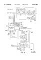
- FIG. 8shows one embodiment of the camera location.
- Broadcast camera 280captures a video frame which is sent to a production center 244 as shown by the signal camera 1.
- Broadcast camera 280has a zoom lens including a 2 ⁇ expander.
- a 2 ⁇ expander/zoom/focus sensor 282(collectively a "zoom sensor") which senses the zoom of the camera, the focal length of the camera, and whether the 2 ⁇ expander is being used.
- the analog output of sensor 282is sent to an analog to digital converter 284, which converts the analog signal to a digital signal and transmits the digital signal to processor 302.
- Broadcast camera 280is mounted on tripod 287 which enables broadcast camera 280 to tilt and pan. Attached to tripod 287 are pan sensor 288 and tilt sensor 290, both of which are connected to pan-tilt electronics 292.
- Remote processor unit 286is a rack mounted system including analog to digital converter 284, pan-tilt electronics 292, processor 302 and front end processor electronics 300.
- Processor 302is an Intel 486 microprocessor with supporting electronics; however, various other processors can be substituted.
- Processor 302includes memory and disks to store data and the software described below.
- processor 302is in communication with graphics center 246, as indicated by signal 306.
- pan sensor 288 and tilt sensor 290are optical encoders that output a signal, measured as a number of clicks, indicating the rotation of a shaft. Forty thousand clicks represent a full 360 degree rotation.
- a computercan divide the number of measured clicks by forty thousand and multiply by 360 to determine the pan or tilt angle.
- the pan and tile sensorsuse standard technology known in the art and can be replaced by other suitable pan and tilt sensors known by those skilled in the relevant art.
- Pan-tilt electronics 292receives the output of pan sensor 288 and tilt sensor 290, converts the outputs to a digital signal, representing pan and tilt, and transmits the digital signal to processor 302.
- the pan, tilt and zoom sensorsare used to determine the field of view of the broadcast camera and, in some cases, the field of view of an infrared sensor.
- one or more of the pan, tilt or zoom sensorscan also be labelled as a field of view sensor.
- the field of view sensorwould only include a pan sensor.
- One alternative field of view sensorincludes placing marks in various locations on the hockey rink such that each mark looks different and at least one mark will always be visible to the camera while the camera is pointed at the hockey rink.
- a computer using optical recognition technologycan find the mark in the video frame and, based on the mark's size and position in the video frame, determine the field of view and/or pan, tilt and zoom of the camera.
- Another alterativeincludes placing infrared emitters or beacons along the rink (e.g. on the glass).
- a computercan determine the infrared sensor's field of view based on the size of the received signal's size and location in the infrared sensor's frame of data. If an infrared sensor is mounted on a broadcast camera, determining the pan and tilt of one also determines the pan and tilt for the other (plus a known offset). Another alternative includes using pan and tilt sensors to get a rough estimate of field of view and using beacons to fine tune the field of view determination.
- the camera locationalso includes two infrared sensors, master sensor 296 and slave sensor 298, both of which are connected to front end processor electronics 300 and sensor interface box 320.
- master sensor 296 and slave sensor 298are mounted near one another (e.g. next to each other) so that their optical axes are near each other. It is possible to mount the two sensors away from each other and correct for the misalignment of optical axis.
- both sensorsare mounted on broadcast camera 280 so that they are pointed in the same direction as broadcast camera 280.
- Pan sensor 288 and tilt sensor 290will indicate where the master and slave sensors are pointing. However, it is not necessary to mount the sensors on the broadcast camera.
- the internal clocks of the master sensor 296 and slave sensor 298are synchronized as indicated by signal 305.
- the preferred infrared sensoris a progressive scan, full frame shutter camera, for example, the TM-9701 by Pulnix.
- the Pulnix sensoris a high resolution 768(H) by 484(V) black and white full frame shutter camera with asynchronous reset capability.
- the camerahas an eight bit digital signal output and progressively scans 525 lines of video data.
- a narrow band infrared filterwhich passes electromagnetic waves of approximately 880 nm +/-45 nm, is affixed in front of the lens of the Pulnix sensor. The purpose of the filter is to block electromagnetic signals that are outside the spectrum of the signal from the puck; thus, significantly reducing background clutter.
- Each sensorcaptures a video frame which comprises a set of pixels. Each pixel is assigned a coordinate corresponding to an X axis and a Y axis.
- the sensor dataincludes an eight bit brightness value for each pixel. The eight bit brightness values are scanned out pixel by pixel to front end processor electronics 300 from master sensor 296 via the signal Mdata and from slave sensor 298 via the signal Sdata.
- Sensor interface box 320sends the shutter command and horizontal drive to the infrared sensors.
- Signal 446 from the pulse detection system(described below) is decoded by sync decoder 322 to extract horizontal drive signal 321 which is communicated to master sensor 296.
- Horizontal drive signal 321is used to phase lock the master sensor's internal clock to the puck.
- Signal 321is also sent to pulse generator circuit 324 to produce a shutter control signal (Mshutter) at least 120 ⁇ sec wide, which is transmitted to master sensor 296.
- the output of pulse generator 324is also sent to delay circuit 326 to provide a signal delayed by approximately 60 ⁇ sec for pulse generator 328.
- the output of pulse generator 328, an approximately 120 ⁇ sec wide pulse used to control the shutteris sent to slave sensor 298.
- Both shutter control signals(Mshutter and Sshutter) are also sent to computer 286 for diagnostic purposes.
- strobe flashesAt or near the ceiling of the arenas and provide for communication between each photographer's camera and the set of strobe flashes.
- the strobe flashesemit a flash of light, which may include an electromagnetic wave in the infrared spectrum.
- the systemavoids incorrect data due to a sensor detecting a flash by ignoring data sensed during a flash.
- One means for preventing the incorrect datais to use filters.
- a second embodimentconnects a signal from the strobe flash to the sensors or a computer which causes the system to ignore data sensed during a flash.
- a third embodimentincludes using flash detectors.
- the flash detectorscan be located anywhere in the arena suitable for sensing a strobe flash.
- one alternativeincludes a flash detector 329 as part of the sensor interface box 320. When flash detector 329 senses a flash a signal FD is sent to front end processor electronics 300. In some environments, a flash detection system may not be necessary.
- Each sensor locationincludes two sensors in master and slave configuration. Sensors 210-216 are preferably mounted above the rink so that the field of view of the sensors overlaps and each location on the ice is within the field of view of two sensors. Sensor locations 210, 212, 214 and 216 do not include broadcast cameras and pan/tilt/zoom detectors. Since the sensor at sensor locations 210-216 cannot pan, tilt or zoom, control system 606 (FIG. 15) stores the location, pan and tilt of the sensors. Each sensor location also includes a processor 302 and front end processor electronics 300.
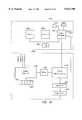
- FIG. 9shows a block diagram of front end processor electronics 300.
- Sensor interface 330receives data (Mdata) from master sensor 296, including the eight bit data for each pixel.
- Sensor interface 330has four output signals: LDV, FDV, PC1 and DATA1.
- LDVline data valid
- FDVframe data valid
- PC1pixel clock 1
- DATA1is transmitted to background processor 334.
- XY counters 332counts X and Y coordinates sequentially in order to keep track of the pixel of whose data is being scanned in at the current time.
- LDVis asserted
- FDVis asserted
- the Y counteris reset.
- frame limits 336determines whether the coordinate of the particular pixel being scanned in is within the valid frame limits.
- the valid frame limitsincludes pixels in a rectangular box within the frame of the sensor 296 which is determined by the values of X min , X max Y min , and Y max , all four of which are supplied from registers in processor 302 via computer interface 339.
- the registers in processor 302are set by software in computer 606. (See FIG. 15.) These values can be set based on the sensor location and orientation. For example, if half of the field of view of the sensor 296 is above the hockey rink or below the hockey rink, there is no need to consider data that is not within the hockey rink. This avoids sensing spurious sources.
- the signal INFRAMEis asserted and transmitted to pixel gate control 338.
- Sensor interface 340receives data (Sdata) from slave sensor 298 and communicates the eight bit pixel data and PC2 (pixel clock two) to adjustable delay 342. There is no need to send a version of the signal LDV and FDV for slave sensor 298 because master 296 and slave 298 are synchronized by signal 305 (FIG. 8).
- Adjustable delay 342is an adjustable shift register for aligning the optical data from the master and slave sensors. The amount of delay is determined by the variable OFFSET which is a twelve bit signal sent from processor 302 via computer interface 339. OFFSET is set in processor 300 via a user interface residing on computer 606 or a local user interface. (See FIG.
- the data from the two sensorsare optically aligned because the two sensors will be mounted on top of each other or next to each other, therefore, having different optical axes.
- One alternativeis to use one optical axis for both sensors, for example, using a prism to transmit one image to two sensors, which in turn are optically aligned.
- the delayed data(PC2 and DATA2D) is transmitted to background processor 334.
- Background processor 334is an Arithmetic Logic Unit with a set of registers. Alternatively, background processor 334 could be a microprocessor. Background processor 334 aligns the data based on the pixel clocks and subtracts the two sets of data (DATA1 and DATA2). There are two types of subtraction that can be used; temporal subtraction and spectral subtraction, although either or both methods can be used, the preferred background processor 334 only performs temporal subtraction.
- the technique of temporal subtractionutilizes two sensors with similar field of views, opening their shutter at different times. The master sensor's shutter is open and captures data during an infrared pulse from puck 10. The slave sensor's shutter is open and captures data between pulses from puck 10.
- master 296 and slave 298sense substantially similar images except master sees the field of view with the puck on and slave sees almost the same field of view without the puck. If the two sets of data are subtracted, the difference should be the signal from the puck. Background processor 334 performs that subtraction.
- master sensor 296opens its shutter for 127 ⁇ sec. After master sensor 296 closes its shutter, both master and slave keep their shutters closed for 63 ⁇ sec. Subsequently, slave 298 opens its shutter for 127 ⁇ sec. followed by both shutters being closed for the remainder of the frame's 1/30 of one second. This process repeats itself approximately every 1/30 of a second based on the strobing of the puck which will be described below.
- Spectral subtractionutilizes two sensors that have substantially similar field of views, but detect different spectrums.
- One spectrumincludes the puck's pulse and the second spectrum does not.
- master 296would use the filter discussed above which passes wavelengths of 880+/-45 nm.
- slave 298would use a filter that allows a bandwidth near but not including the bandwidth of master 296.
- the shutters of both the master 296 and slave 298would open and close at the same time, creating two sets of data. Theoretically, the two sets of data would differ in that one would include the puck and one would not. Subtracting the two sets of data causes most data to cancel out, except for the puck's signal.
- the output of background processor 334is eight bit DATAS which is sent to pixel gate control 338 and FIFO 344.
- Pixel gate control 338is used to determine whether data is valid and to store that data in FIFO 344.
- Pixel gate control 338uses three criteria to determine whether the data is valid. The first criteria is to determine whether the data is within the valid frame limits. The second criteria is to determine whether the data has met a certain brightness THRESHOLD. Certain pixels are so dim that they cannot be valid data.
- a variable THRESHOLDis used as a brightness threshold. All data with a brightness below the THRESHOLD value is discarded.
- Pixel gate control 338receives THRESHOLD from register processor 302 via computer interface 338.
- THRESHOLDis set from a graphical interface in computer 606 (or a local interface) based on the environment surrounding the sensors and will usually be determined by trial and error or measurement at each sensor location.
- the third criteria to determine whether the data is validis to find out whether the data was captured during a flash.
- sync/sensor control 346receives a signal FD indicating a flash and forwards this signal to pixel gate control 338. If pixel gate control 338 determines that the coordinates of the pixel are within the frame limit, DATAS is above the THRESHOLD and there is no flash during the frame, pixel gate control will assert W (write enable) to FIFO 334 to cause FIFO 334 to store the pixel coordinates (X,Y) from XY counters 332, a data code and eight bit DATAS.
- the data codeindicates whether FIFO 334 is storing valid data, a strobe flash indicator (SF), an end of frame indicator (EOF) or a start of frame indicator (SOF). If the data is not within the frame limits, or not above the THRESHOLD, pixel gate control 338 will not assert W. If there is a flash during a frame, pixel gate control 338 will assert W, and store SF in the data code field.
- SFstrobe flash indicator
- EAFend of frame indicator
- SOFstart of frame indicator
- Background processor 334also sends output signals DATA0D (16 bits), PC1D (2 bits), FDVD (2 bits), and LDVD (2 bits) to optional data monitors.
- DATA0Dis DATAS sent as differential data.
- PC1Dis pixel clock 1 sent as differential data.
- FDVDis frame data valid sent as differential data.
- LVDVis line data valid sent as differential data.
- Computer interface 334also transmits a reset signal to FIFO 344 to reset the FIFO when the system is being started up.
- Processor 302via computer interface 348, sends a read control signal 350 to FIFO 344 in order to request data from FIFO 344.
- the output of FIFO 344is a 32 bit data signal 352 which is sent to computer interface 348 which aligns the data and presents the data to processor 302.
- FIG. 10describes the operations in the camera location and related hardware.
- the first step depictedis registration and initialization 380. This step, which will be discussed in more detail below, includes initializing and calibrating the hardware.
- broadcast camera 280begins selectively broadcasting the hockey game (step 382) and, concurrently, steps 384-406 are performed. By selective broadcasting it is meant that the broadcast camera captures video images and sends those images to production center 244. A manager in production center 248 may or may not use those particular video images.
- step 384puck 10 is turned on (e.g. starts pulsing). While puck 10 is transmitting pulses, one or more pulse detectors (discussed below) detect the puck's pulses and a shutter command is sent to the infrared sensors (step 386). Although step 386 is drawn above step 388, step 386 is continuous and occurs before, after and/or during step 388. During normal operation, two sets of operations occur: steps 388-392 and steps 394-404. In step 388 analog to digital converter 284 and pan-tilt electronics 292 sample the pan, tilt and zoom values. In step 390, these values are sent to processor 302 which transmits the values to graphics center 246.
- processor 302receives the X and Y boundaries (X min , X max , Y min , Y max ) from graphics center 246 and transmits those values to frame limits 336 via computer interface 338.
- the X and Y boundariescan be determined by processor 302.
- master sensor 296opens its shutter for 127 ⁇ sec and captures (or creates) data representing a position of puck 10 in the field of view of master sensor 296.
- slave sensor 298opens its shutter for 127 ⁇ sec. and captures (or creates) data.
- datais serially scanned in for each pixel for both sensors. Step 398 could be divided into two separate steps.
- step 402false detections (including noise) are removed, which includes subtraction, brightness threshold, frame limits, flash detection, region of play filters and exclusion zones. Region of play filters and exclusion zones are discussed below.
- the systemalso utilizes pulsing, infrared filters on the sensors and infrared reduction through filtering or polarization of spurious sources for assisting the detection of the puck's signal from noise and clutter.
- the infrared reductionis accomplished by placing filters that remove infrared signals in front of all or some of other electromagnetic emitting sources in the arena (e.g. scoreboard).
- the systemuses the above listed methods to enhance performance, a system can be designed to function without any of the listed methods or with a subset of the listed methods.
- the data that passes the tests of step 402tends to be represented as clusters of pixels.
- the systemcan save time transferring sensor information from the camera location to the graphics processing center 246 by sending information which characterizes the clusters instead of individual pixel values. Characterizing these clusters is the tasks performed in step 404.
- the advantage of clusteringis that it saves bandwidth and distributes computer power.
- a clusteris defined as a group of valid pixels that border each other.
- FIG. 11shows a portion of a frame of data. For example purposes only, the THRESHOLD value set for this particular frame of data is eight. Thus, only pixels that have the brightness of eight or greater are stored in FIFO 344. Each square in FIG. 11 represents a pixel and the number in that square represents the brightness of the pixel.
- the pixels with no numbershave a brightness less than eight.
- the portion of the frame depictedincludes two clusters 430 and 432.
- the first row of cluster 430includes three pixels having brightness of eight.
- the second row of cluster 430includes four pixels having brightness of nine.
- the first row of cluster 432includes two pixels, the first pixel having a brightness of eight and the second pixel having a brightness of nine.
- a data structureis set up analogous to a structure in the C programming language.
- the fields of the structureinclude MINX, MAXX, MINY, MAXY, TOTAL ENERGY and MAX ENERGY.
- MINXis the minimum X value of any of the pixels in the cluster.
- MAXXis the maximum X value of any of the pixels in the cluster.
- MINYis the minimum Y value of any of the pixels in the cluster.
- MAXYis the maximum Y value of any of the pixels in the cluster.
- the X and Y valuesare the coordinates of pixels in the frame. For example, point 436 has the coordinates 96, 198 and point 434 has the coordinates 100, 200.
- TOTAL ENERGYis the sum of the brightness of all of the pixels in the cluster, and MAX energy is the brightness of the brightest pixel in the cluster.
- MAX energyis the brightness of the brightest pixel in the cluster.
- FIG. 12shows a pulse detection system, which is one type of a synchronization system that can be used to synchronize the sensors with the object being tracked.
- Lower collector box 220sends power to pulse detectors (440) and flash detectors (440-442) and receives a signal from pulse detectors 222-240 indicating a puck pulse.
- pulse detectors 222-240can be self-powered.
- the systemcan optionally include pulse detectors 443 above the rink (e.g. hanging from ceiling) or another location.
- Upper collector box 445sends power to pulse detectors 443 and receives a signal from pulse detectors 443 indicating a pulse.
- Upper collector box 445effectively wire-ORs the signals from pulse detectors 443 and sends the result to lower collector box 220.
- Collector box 220effectively wire-ORs the output signals from the pulse detectors 220-240 and upper collector box 245 and sends the result to synchronizer box 440 which resides in graphics center 246.
- the systemcan include additional pulse detectors connected to additional upper collector boxes. Each upper collector box would have an output which is connected as an input to another collector box to be wire-OR'ed with the pulse detectors of the other collector box.
- Lower collector box 220receives a signal from each of the flash detectors 442 and effectively wire-ORs the signals. If any of the flash detectors 442 sense a flash, collector box 220 will ignore any pulses detected during the same time period as the flash. Thus, flash detectors 440 are a second (and optional) flash detect system in addition to the flash detectors at the camera locations.
- Synchronizer box 444receives the puck pulse signal on line 221 from lower collector box 220. Based on the signal from the pulse detectors, synchronizer box 444 determines the period of the puck. Synchronizer box 444 sends to each infrared sensor location and camera location a signal 446 which is used to synchronize the shutter of the infrared sensors.
- FIG. 13shows a block diagram of a pulse detector.
- the heart of the pulse detectoris a photodetector 450 which includes a photo diode and op-amp.
- Photodetector 450is also connected to DC subtraction circuit 454.
- FIG. 13shows two connections between photodetector 450 and DC subtraction circuit 454 to indicate that DC subtraction circuit 454 provides feedback to the op-amp in photodetector 450.
- the output of DC subtraction circuit 454is sent to filter 456 which reduces steady DC signals and low frequency AC signals such as 120 Hz power line modulation.
- the output of filter 456is sent to leading edge threshold detector 458, which detects the rising edge of the infrared pulse from puck 10.
- leading edge threshold detector 458Connected to leading edge threshold detector 458 is trailing edge gate 460 which outputs a pulse when leading edge threshold detector 458 detects a leading edge.
- the output of trailing edge gate 460is transmitted to comparator 462.
- Filter 456also transmits its output to trailing edge threshold detector 464 which detects the falling edge of a pulse from puck 10.
- the output of trailing edge threshold detector 464is transmitted to comparator 462.
- Comparator 462determines whether a trailing edge was detected within the pulse created by trailing edge gate 460. If so, comparator 462 outputs an indication that a puck pulse has just occurred.
- Flash detectors 440-442are similar to the pulse detectors except that the narrow band infrared filter 452 is replaced with a filter that allows detection of signals in a wide spectrum that includes signals emitted by puck 10.
- FIG. 14is a block diagram of synchronizer box 444.
- Reference oscillator and buffer 500includes an oscillator operating at 14.31818 MHz (70 nsec clock resolution) and a buffer. This circuit provides timing for circuits 502, 504, 506, 508, 510, 512, and 520.
- Circuit 502is an adjustable counter that nominally provides a delay of 4095 clock pulses (286 ⁇ sec). Circuits 504 and 510 are fixed counters that provide delays of 4092 clock pulses each (285.8 ⁇ sec).
- Circuit 506is an adjustable delay counter that nominally provides a delay of 7675 clock pulses (536 ⁇ sec). Circuits 502, 504, and 506 are started by the pulse detect signal 221. The difference in time delay between counter 506 and counter 502 is used to control the infrared sensor shutter timing in response to the pulse detect signal 221 so that the shutter opens just before a pulse from puck 10 occurs.
- the delayed pulse from counter 506starts counter timer 508.
- the output of counter timer 508starts counter 510.
- the outputs of counters 504 and 510are pulses with a width of 4092 clock pulses (285.8 ⁇ sec) each. In normal operation, the delays provided by the adjustable counter 506 and counter 508 are equal to the period of pulse 221 (approximately 30 Hz).
- the period of counter 508counts an adjustable delay based on a user setable switch and an up/down counter/adder circuit inside counter timer 508 controlled by the output of counters 504 and 510. The count of the up/down counter is determined by the relative overlap positions of the output pulses from counters 504 and 510.
- circuit 514contains diagnostic LEDs to indicate the presence of pulse signals 221 and a "locked" condition on counter 508.
- the counter settings from counter 506 FD 0-15 and counter 508 TD 0-15are added together in oscillator adder circuit 518.
- the counter settingsare also read into a computer (not shown) through a parallel port where they are added and averaged.
- Jumper 519is used to select either the sum from circuit 518 or the computer averaged sum output. Since these sums represent the period for pulse signal 220, they are used to control the period of oscillator counter 512.
- This circuitwill run continuously in the absence of pulses 220 and provides a "coasting" feature to control the shutter of the infrared sensors with or without the presence of the pulses from puck 10.
- the oscillator phaseis reset by the output of counter 502 passing through reset gate 516.
- the gateis opened by the "burst" signal from counter 508. This signal is present during valid pulse tracking intervals and represents the overlap of the pulses from counters 504 and 510.
- the output pulse from oscillator 512starts shutter delay counter 520.
- the output of this counteris sent to phase-locked loop 542.
- the delay count for shutter delay counter 520is selected by jumper 522 from the control values for counter 508 (TD 0-15 ) or from a computer average of the TD 0-15 data.
- the output of counter 520controls camera shuttering and occurs at a nominal rate of 30 Hz. This signal is used to control phase-locked loop 542 running at nominally 15,750 Hz.
- Divider 544divides the output of phase-locked loop 542 by five hundred and twenty five to provide a 30 Hz reference signal that is compared to the output pulse from counter 520, thus controlling the frequency of phase-locked loop 542.
- Pulse generator 546receives the output of phase-locked loop circuit 542 and generates approximately 10 ⁇ sec wide pulses. Pulse generator 548 generates a pulse approximately 30 ⁇ sec wide from the nominally 30 Hz rate out of divider 544. The outputs of circuits 546 and 548 are combined in "OR" circuit 560 and buffered by circuits 562 to provide a "composite sync" signal to the infrared sensors.
- the composite sync signalcontains both a horizontal drive signal (the output of pulse generator 546) and a camera shutter control (the output of pulse generator 548). This composite sync signal is sent to the infrared sensors and decoded by sensor interface box 320.
- pulse detectorsOne alternative to using pulse detectors is to include a receiver (e.g. RF receiver) in the puck.
- a control transmittere.g. similar to that described below
- the central transmitterwould also send a synchronization signal to cause the infrared sensors to open their shutters.
- FIG. 15shows a partial block diagram of graphics center 246 and production center 244.
- Graphics center 246includes a video processor 604 which receives data 602 from processor 302 at each of the camera locations and infrared sensor locations.
- Video processor 604performs the calculations to determine the location of the puck in the arena as well as the position of the puck in the video flame of a broadcast camera.
- the preferred video processor 604is an Indigo Two Impact from Silicon Graphics.
- Video processor 604receives cluster data for all of the infrared sensors and pan/tilt/zoom data for all of the broadcast cameras and saves that data in memory 612 along with timing information. The timing information is stored so that if the data is used at a later time, the processor can determine at what time the data was detected.
- Memory 612in conjunction with disk drives, also stores software used to program processor 604.
- Graphics center 246also includes a control station 606 which is a second computer used as an operator interface. Control station 606 enables the operator of graphics center 246 to change variables (e.g. THRESHOLD), start the system and perform control functions. Graphics center 246 also includes a spare computer 608 which can be used in case either control station 606 or video processor 604 malfunction. Graphics center 600 can function with one computer. All three computers, 604, 606 and 608, communicate with each other over a local area network 610, which is a 10 Base-T implementation of ethernet. Each computer is connected to a Starbase T-9, 10 Base-T hub with twisted pair wiring.
- a local area network 610which is a 10 Base-T implementation of ethernet. Each computer is connected to a Starbase T-9, 10 Base-T hub with twisted pair wiring.
- video processor 604determines the location of puck 10
- video processor 604determines the position of the puck in the video frame of the broadcast camera.
- Video processor 604then creates data which is sent to a video modification unit 616.
- Video control 618which is used to select one broadcast camera for transmission to viewers.
- One embodiment of video control 618includes a plurality of monitors, one monitor for each video signal, and a selection circuit. A director (or manager) would monitor the different video signals and choose which signal to broadcast. The choice will be communicated to the selection circuit which selects one camera signal to broadcast. The choice is also communicated to video processor 604.
- the selected video signalis sent to delay 622.
- the output of delay 622is transmitted to video modification unit 616.
- the purpose of delay 622is to delay the broadcast video signal a fixed number of frames to allow time for video processor 604 to receive data and determine the position of the puck in the video frame.
- the video frameneeds be delayed five frames. Additional delay can be added to allow for interpolation of missed data, as discussed below. Additionally, the hardware and the software can be modified to increase the speed of the video processing which would decrease the delay.
- the videois delayed a small number of frames, the television signal is still defined as live.
- the delay introduced by the systemis a small delay (under one second) which does not accumulate. That is, successive frames are continuously enhanced with the same small delay. For example, a ten frame delay is equivalent to one third of a second, which is not considered a significant delay for television.
- Video modification unit 616modifies the video signal from delay 622 with the data/signal from video processor 604.
- the type of modificationcan vary depending on the desired graphic.
- One exemplar implementationutilizes a linear keyer as video modification unit 616.
- the signal from video processor 604 to the keyerincludes two signals YUV and an external key (alpha).
- the YUV signalis called foreground and the signal from delay 622 is called background.
- the keyerdetermines how much of the foreground and background to mix to determine the output signal, from 100% foreground and 0% background to 0% foreground and 100% background, on a pixel by pixel basis.
- the systemcan also include a data inserter 628 for inserting nonvideo data into a television signal.
- Nonvideo datais information other than the traditional data used by a television to draw the normal scan lines on a television display.
- An example of nonvideo datais data transmitted during the vertical blanking interval, which can be closed caption data, statistics regarding puck 10 (e.g. the puck's location, speed, acceleration etc.), interactive queries or internet addresses.
- inserter 628receives a television signal from video modification unit 616 and nonvideo data from video processor 604, via signal 630. Inserter 630 inserts the nonvideo data into the vertical blanking interval of the television signal and sends the resulting signal to amplifier 626.
- Inserter 630is a standard data inserter known in the art.
- One example of a suitable data insertercan be found in PCT International patent application Ser. No. PCT/US94/13484, which was published on Jun. 8, 1995 with International Publication Number WO 95/15654, which is incorporated herein by reference.
- FIG. 16describes some of the operations in graphics center 246 and processing center 248.
- the pan, tilt and zoom datais received by video processor 604 from the various processors (e.g. processor 302).
- cluster datais received from the processors (e.g. processor 302).
- video processor 604stores the pan/tilt/zoom information for all broadcast cameras and the cluster data in memory 612.
- video processor 604determines the three dimensional location of puck 10.
- the systemremoves false detections. As discussed above, there are various means for removing false detections, some of which can be performed both by a processor at the graphics center. Preferably, region of the play filters and exclusion zones are accomplished at the graphics center, although the inventors do contemplate performing variations of these methods at sensor locations.
- Exclusion zonesare known areas of false data. For example, there may be a camera with a light near the arena, or any other light near the playing surface (e.g. light indicating a penalty, timeout, etc.). It is possible for these lights to emit an infrared signal. Since the existence and locations of these sources are known, they can be removed from the data considered by the video processor in determining the three-dimensional location.
- One method for ignoring an exclusion zoneis after determining the three-dimensional location of the puck, if that location is in an exclusion zone, then ignore that location data. For example, in some instances, the system determines one or more possible locations of the puck. If any of these locations are in the exclusion zone, that location is removed from consideration.
- the video processorcan ignore all lines of position that pass (or substantially pass) through an exclusion zone.
- Another alternativeincludes the electronics at the sensor ignoring any cluster that would give rise to a line of position into an exclusion zone.
- Another alternativeincludes manually entering all exclusion zones for each sensor that is fixed (e.g. no pan or tilt) before the sporting event begins. This can be done at graphics center or the central location. If a sensor can pan or tilt, the processor at the sensor can be given the three-dimensional location. Exclusion zones can also be defined in two dimensions for a camera or sensor. The exclusion zone can be manually entered at one of the processors or an operator in the production center can identify the exclusion zone using an input device (e.g. mouse) in connection with a monitor (video or sensor data).
- an input devicee.g. mouse
- Field of play filtersare software methods for ignoring data that indicate a location outside the field of play.
- the systemcan be programmed with the three dimensional coordinates of the hockey rink, for example, the X and Y coordinates of the hockey rink and a Z axis height limit (e.g. twenty feet). Any data indicating a location of the puck outside of these limits will be ignored.
- step 652video processor 604 determines the puck's position in the video frame of the selected broadcast camera.
- step 654the television presentation of the selected broadcast camera is enhanced.
- the enhancementincludes video processor 604 creating a frame of data with a graphic at the position of the puck in the video frame of the broadcast camera.
- the frame of data created by video processor 604is sent to video modification unit 616 which combines the frame of data sent from video processor 604 with the frame of data from the selected broadcast camera.
- step 656the enhanced video frame is transmitted for broadcast or stored for later use.
- the graphiccould be a larger puck, a flashing puck, an icon, a trail of fire, an opaque cloud on top of the puck, any combination thereof, or any other graphic which highlights the video presentation of the puck.
- the graphiccould also be logically near the position of the puck, for example, a trail of fire behind the puck, a trajectory of the puck's path, a target at the end of the pucks trajectory, an arrow pointing to the puck, etc.
- the enhancementcould also include audio data, for example, a sound related to the speed or acceleration of the puck, or a sound indicating that the puck is at the certain location.
- Other examples of enhancementsincludes nonvideo data; statistics displayed on the television related to the puck's position, location, speed, acceleration, etc.
- the step of enhancingincludes combining data (e.g. a keyer), editing data and creating data.
- FIG. 17Ais a flow chart explaining the determination of the puck's three dimensional location (step 648 in FIG. 16).
- One alternativeinvolves determining lines of position. Once lines of position are known, there are many suitable methods to determine three dimensional location.
- FIGS. 17A and 17Bexplain two exemplar methods.
- step 680 of FIG. 17Avideo processor 604 determines a line of position (LOP) for each cluster of each sensor.
- LOPline of position
- the LOPis first calculated in "camera space", the coordinate system where the infrared sensor is at the origin looking along the negative Y axis, with the X axis on the right and the Z axis up. The LOP is then transformed into the three dimensional coordinate system of the arena.
- the sensor focal length and aspect ratioare measured in advance on an optical bench. This measurement indicates that a target a meter away if moved one pixel to the side moves h meters in space, and if moved one scan line up or down, moves v meters in space. From these ratios, given that the cluster is x pixels and y scan lines from the center of the sensor field of view, a vector is constructed:
- a line of positionis represented as a point and a vector:
- a point in three dimensional spaceis represented by a 4 element row vector: (x, y, z, 1.0).
- the 1.0(sometimes called w) allows for translation.
- point Pis (0,0,0,1.0) since the sensor is at the origin.
- the LOPis a parametric representation of a line, since any point on the line can be represented as:
- An LOPis transformed into the three dimensional coordinate system of the arena by a 4 ⁇ 4 matrix.
- the three element vectoris multiplied by the inverse transform of the upper left 3 ⁇ 3 matrix of the 4 ⁇ 4 matrix.
- the four element pointis multiplied by the 4 ⁇ 4 matrix.
- the matrix (X)models the fixed position and orientation of the broadcast camera.
- the matrices (ABCD)model the movement of the broadcast camera (e.g. pan, tilt, etc.).
- the matrix (O)has the same form as the matrix (X) and models the positional and rotational offset of the infrared sensor from the top surface of the camera head. ##EQU2##
- Pan and tilt anglesare measured with the pan and tilt sensors 288 and 290.
- the forward offset distanceis the distance that the tilt axis is positioned forward of the pan axis.
- the forward offset distance and optical axis heightcan be measured directly from the camera head with a ruler.
- the tilt risewhich is the distance from the nominal position that the camera plate rises, can also be measured with a ruler and a lookup table built as a function of tilt angle.
- the POVpovdist
- First Principal Point, or Front Nodal Pointis the position of the camera's virtual point of view measured as a distance forward of the tilt axis when the camera is in the horizontal position.
- the POVcan be measured on an optical bench and a lookup table built as a function of zoom position, focus, and 2 ⁇ setting.
- the POVis measured by placing two targets in the field of view of the lens, off-center, one farther away than the other, so they appear in line through the viewfinder. Where a line extended through those targets intersects the optical axis of the camera is the position of the virtual POV.
- the effective horizontal and vertical focal length of the lens (f h and f v )are the half-width and -height of the camera's field of view at some distance divided into that distance. This is measured on the optical bench and a lookup table built as a function of zoom position, focus, and lens doubler.
- the aspect ratiois f h /f v and is constant, so usually f v is modeled for given settings and f h is equal to aspect multiplied by f v .
- video processor 604groups all possible pairs of LOPs (step 682). For each pair of LOPs, video processor 604 finds the closest point of contact of the two LOPs (step 684). If the LOPs do not intersect the closest point of contact will be two points, one on each LOP. The line connecting the two points is perpendicular to both LOPs. To simplify the calculations, one embodiment contemplates using the midpoint of the line perpendicular to both LOPs as the closest point of intersection. However, both points can be used in the steps described below.
- video processor 604now has a set of points of closest contact.
- video processor 604finds a center of all of the points of closest contact. The center is the average of the coordinates of the points of closest contact.
- video processorfiguratively draws a sphere around the center point. The radius of the sphere is predefined. The radius should be big enough to allow the system to function, but small enough so that improper data is thrown out. In one embodiment, the radius is set as one meter. Each time the system is set up, a user may need to use trial and error to determine the proper radius.
- video processor 604determines whether all the points fit within the sphere.
- video processor 604in step 692, removes the furthest point and loops back to step 686. If all the points do fit within the sphere, then the average or center of the sphere is a candidate for the three-dimensional location of puck 10.
- One alternativeis to reduce the radius for each iteration, keep iterating until the minimum radius is reached (e.g. 0.1 meter) and if there are a predefined number of points remaining (e.g. ⁇ 2) then a valid three dimensional location candidate had been found.
- Another alternativeincludes reducing the radius for each iteration, removing all points outside the sphere for each iteration, continue iterating until the minimum radius is reached (e.g.
- the points of closest contactmay form more than one separate groups of points, in which case the method of FIG. 17A can be repeated for each group of points and more than one location candidate will be determined.
- the incorrect candidatesshould be removed when removing false detections in step 650 of FIG. 16.
- FIG. 17Bdescribes one exemplar method for using lines of position and probabilities to determine three-dimensional location.
- lines of positionare determined for each cluster of each sensor.
- the systemdetermines cones for each line of position. That is, each line of position can be thought of as a set of cones, one inside the other. Each cone represents a space with an assigned probability for the puck being within that space.
- the set of conesis projected onto the playing surface.
- a set of cubesare figuratively created. A first layer of cubes lie on the playing surface.
- a second layer of cubesare located above the first layer, and so on. Each cone is projected such that it passes through one or more cubes. For each line of position, each cube is assigned a probability equal to the probability of the cone passing through the cube. If more than one cone for a particular line of position passes through a cube, the cube is assigned the probability of the highest probability cone passing through it. If a cube lies within cones from more than one line of position, a cube will be assigned more than one probability. Each of the probabilities assigned to each cube are added and the sum is stored for each cube (step 702). If a cube was assigned only one probability, then that one probability is the stored sum.
- the cube with the highest probability sumis assumed to be the cube where the puck is (step 704).
- the cubesare small enough so that the resolution of the cube is sufficient to find the puck in one iteration.
- the playing surfaceis divided into a small set of large cubes and step 704 determines which of the large cubes the puck lies in. Since the resolution of the cubes is not fine enough for the puck determination to be accurate, the process is repeated (in step 706) by looking back to step 700, dividing the one cube which contains the puck into smaller cubes, the probability is added up for the smaller cube and the system determines which of the smaller cubes contains the puck. If the resolution of the small cube is sufficient, the method ends; otherwise, the method performs another iteration.
- the inventorscontemplate numerous other equivalent implementations that make use of the probability of the puck's location that are within the spirit of the present invention.
- FIG. 18is a flow diagram describing one exemplar embodiment of how video processor 604 determines the position of the puck in the video frame of the selected broadcast camera and creates data which is sent to video modification unit 616.
- video processor 604transforms the three dimensional location of the puck to a two dimensional position in the video frame of the selected broadcast camera.
- a broadcast camerais represented mathematically by a 4 ⁇ 4 matrix which includes details of position and orientation.
- the three dimensional pointis transformed into a two dimensional normalized frame location by multiplying the point by the camera matrix (K).
- the camera matrix (K)in its simplest form is a combination of rotation, translation, and perspective elements, all of which are represented by 4 ⁇ 4 matrices.
- the broadcast camerais modeled as a 4 ⁇ 4 matrix which includes two parts--a fixed transformation (X) which represents the position of the camera in the arena and its orientation, and a variable transformation (V) which varies with changes in pan angle, tilt angle and the zoom:
- the fixed transformation matrix (X)models x, y, z position as well as fixed yaw, pitch and roll representing the camera's mount orientation:
- variable transformation matrix (V)models not just the pan and tilt rotations, but also the complicated way the POV of the camera moves as it pans, tilts, and zooms.
- Vvariable transformation matrix
- Matrix (A)models the camera'pan on its fixed base.
- Matrix (B)models the tilt axis as a fixed distance forward of the pan axis.
- Matrix (C)models the tilt axis as a variable distance above the plane of the top of the tripod--the camera is raised as it tilts away from horizontal to counteract the tendency for it to flop forward or backward. The rise is a function of tilt.
- Matrix (D)models the camera's tilt angle.
- Matrix (E)models the optical axis of the lens as some fixed distance above the tilt axis.
- Matrix (F)models the lens moving forward and backward along the optical axis of the lens as a function of zoom.
- Matrix (G)models the effective focal length of the lens as a function of zoom, focus, and lens doubler (2 ⁇ ) settings.
- step 712 of FIG. 18the graphic (if any) is scaled for the field of view of the broadcast camera.
- the field of view of the broadcast camerabased on location, pan, tilt and zoom, determines how big the puck should be in the video frame.
- video processordraws a black window and then places a graphic at or near the location of the puck.
- step 716the window is sent to video modification unit 616.
- the present invention systemis capable of performing look ahead processing. That is, due to frame delays, one embodiment of the present system can look at video frames and accompanying data for frames captured after the current frame being processed. This information can be used to enhance the processing at the current frame.
- look ahead processingis interpolation.
- video processor 604may not receive data for a particular video frame of the broadcast camera. In such a situation, if only one or a small number of frames of data are lost, it is possible that video processor 604 can interpolate the location or position of the puck so that the enhancement of the television presentation of puck 10 will be continuous.
- FIG. 19shows a symbolic video frame which includes four images of puck 10 superimposed on the same frame.
- F 0signifies the location of the puck during frame 0.
- F 1signifies the location of the puck during frame 1.
- F 2represents the location of the puck during frame 2
- F 3represents the location of the puck during frame 3.
- video processor 604did not receive any data and, thus, interpolates the position of puck 10 during frame 2. Therefore, the puck is dotted for F 2 .
- FIG. 20describes the process of interpolating the location of the puck.
- step 730the pan/tilt/zoom data is received.
- step 732video processor 604 attempts to receive cluster data, similar to step 642 in FIG. 16. Since no useful cluster data is transmitted, video processor 604 waits for the next video frame of data.
- Step 734includes steps 640-650 (or 640-652) of FIG. 16. After the location of the puck is determined for the next video frame, video processor 604 considers the location of the puck before and after the lost video frame in order to interpolate where the puck should have been during the lost video frame (step 736). As discussed above, before a broadcast frame of data is sent to video modification unit 616 it is delayed five frames.
- video processor 604In order to interpolate for one frame of lost data, video processor 604 needs to wait for an extra frame of data. This extra delay is added to the five frame delay discussed above. Thus, the total delay is six frames. If video processor 604 interpolates for five frames of data, then it needs five extra frames of data for a total delay of ten frames, and so on. Thus, under the current system, if video processor 604 can interpolate for N frames of lost data then the broadcast camera video frames must be delayed (e.g. at delay 622) five plus N frames. After the system interpolates to find the position of the puck, the video is enhanced (step 742) and transmitted (step 744).
- FIG. 21depicts additional hardware at the viewer's home which allows for additional enhancement for the television presentation based on the nonvideo data.
- Television signal 748is received by television 750 via cable, a conventional antenna or any other suitable means. The signal can also be sent to a decoder 752 or computer 754.
- Computer 754is in communication with decoder 752 and television 750. Decoder 752 uses technology known in the art to remove data from the vertical blanking interval of a television signal. In one alternative, the function of decoder 752 is performed by computer 754.
- Television 750can also include a VCR or other videotape machine.
- Computer 754includes a monitor 756 which displays windows (e.g.
- decoder 752strips out the nonvideo data from the vertical blanking interval. Decoder 752 sends the data to computer 754 which can display the data in window 762.
- Video processor 604can also be pre-programmed such that when certain events occur (e.g. relative to the location of the puck), video processor 604 inserts one or more addresses of web pages on the internet into the vertical blanking interval of the television signal. As decoder 752 strips out these addresses from the vertical blanking interval, computer 754 can display these addresses on window 762 and allow the user to click on the address with a mouse or use some other user input means which will cause software in the computer 754 (e.g. Mosaic or Netscape) to load the addressed web page.
- software in the computer 754e.g. Mosaic or Netscape
- a television signalis received at the viewer's home and is transmitted directly to computer 754.
- Computer 754will then display a window 760 which would show the televised sporting event.
- a viewercan be provided with remote control capabilities.
- Video processor 604can determine the position of the puck in the broadcast video frame but not enhance the broadcast video. The puck's position is inserted into the vertical blanking interval of the broadcast signal and sent to the viewer's home. Decoder 752 strips out the location of the puck from the vertical blanking interval and sends the location to computer 754.
- Computer 754also receives the video signal and displays the sporting event in window 760.
- Computer 754includes software to add a graphic overlay at the position of the puck in window 760.
- Window 758could be used as a user interface to allow the viewer to turn on or off the enhancement of the puck or to choose what enhancements should be made.
- computer 754can send the enhanced video to television 750.
- the software used to program computer 754, and all of the software described above,can reside in memory, on a disk or any other computer readable medium.
- the registration processincludes initializing the system. As discussed above, at least one embodiment of the system determines the three dimensional location of the puck. Since location is relative, the system needs a reference point. Thus, the first step is to establish a coordinate system, which is accomplished by using X,Y,Z axes with the origin or center point (0,0,0) being at the center of the hockey rink. Three or more registration points (e.g. nine) are marked on the rink in addition to the center point. The distance from the center point can be measured for each registration point so that the coordinates of the registration points are known. The broadcast cameras and the sensors can be registered by solving for the unknown variables in the above described matrices.
- Registering the broadcast camerainvolves the determination of the matrix (X).
- a broadcast camerais pointed at each registration mark in turn, centering the registration mark in the field of view using the center reference mark in the viewfinder.
- the pan and tilt anglesare read and the variable part of the camera transform is calculated for each mark using an arbitrary constant zoom value. (Zoom is not a factor in these comparisons as each registration mark is centered in the field of view. Some constant value is used so errors of different registration marks can be directly compared.)
- An initial educated guess at the fixed transformation parameterse.g. x, y, z, yaw, pitch, roll
- the fixed component matrixis calculated.
- the fixed matrix (X)is concatenated (multiplied) with the variable matrix (V) for each registration point to obtain the composite camera matrix. Then, the three dimensional location of the registration point is transformed by the composite camera matrix to a two dimensional position in the broadcast camera's video frame. An error is determined representing the distance from the calculated two dimensional position to the center of the video frame. The fixed transformation parameters are varied and the process is repeated until the error is minimized, at which point the camera is registered and the resulting fixed matrix (X) is used for subsequent calculations.
- infrared emittersare placed at the registration points.
- An initial educated guessis made at the parameter values for the transformation matrix (J) and the three dimensional locations of the registration marks are determined using matrix (J).
- An erroris determined between the calculated locations (via the matrix) and measured locations of the registration marks. The parameters are varied and the process is repeated until the error is minimized, at which time the sensor is registered and the resulting matrix is used for subsequent calculations.
- Registering a camera-mounted infrared sensoris the process of determining the matrix (O).
- First the broadcast camera on which the infrared sensor is mountedis registered (the X matrix is determined).
- Infrared sourcesare placed at the registration marks and the broadcast camera is oriented to give the sensor a view of the infrared sources.
- the pan and tilt anglesare read and the ABCD matrices are calculated.
- Matrix (G)is calculated using the measured focal length of the sensor.
- Matrix (O)is the only undetermined part of the equation.
- a first educated guessis made at the matrix (O) parameters and the composite transformation matrix is calculated.
- the three dimensional locations of the registration marksare calculated using the transformation matrix and an error is determined between calculated location and the measured location of the registration marks.
- the parametersare varied and the process is repeated until the error is minimized, at which time the sensor is registered and the determined matrix (O) is used for subsequent calculations.
- the x, y, z offsets of the infrared sensor relative to the camera platecan be measured directly rather than solving for them. Measuring directly is generally more accurate.
- the location and orientation of the broadcast cameras and sensorscan be measured relative to the center location.
- a tape measurecan be used to determine the position of the cameras and sensors, or the cameras and sensors can be surveyed.
- the above described systemdetermines the three dimensional location of the puck in order to enhance the video and/or audio for any broadcast camera whose pan/tilt/zoom and location are known.
- the inventorsalso contemplate a system that does not determine the three-dimensional location of the puck.
- Such a systemcould include one infrared sensors (or master-slave configuration) attached to or fixed near the broadcast camera.
- the video processorreceives clusters from one infrared sensor and creates a line of position for one clusters. Various criteria can be used to determine the one cluster, for example, the brightest cluster. Since there are no clusters from other infrared sensors, a three dimensional location of the puck cannot be determined.
- Video processor 604transforms the line of position from camera space to the three dimensional coordinate system of the arena.
- a pointis selected along the line of position at a fixed distance from the camera, and that point is assumed to be the three dimensional location of the puck. Although the point is not the actual location, it will be in line with the actual location. If the system misses a frame of data, the video processor can interpolate in a manner similar to that described above. However, rather than interpolate the puck's three dimensional location, the video processor interpolates the puck's position in the video frame.
- the systemincludes replay decks 620 that can store video, with timing information, for short term use (instant replay) or long term use.
- Memory 612stores the pan/tilt/zoom data for the broadcast cameras, data representing the location and/or position of the puck, and timing information.
- memory 612can store the cluster information and the necessary parameters of the transformation matrices.
- the systemstores all of the information necessary to enhance video subsequent to the live event. For example, between periods of a hockey game an announcer may wish to describe a particular play. The video for the play can be recalled from deck 620 and by matching the timing information, the corresponding data can be read from memory 612 and the system can perform all or part of the methods of FIGS. 16-20.
- the infrared technology disclosed abovecan be used in conjunction with the television presentation of sporting events other than hockey.
- the infrared transmittercan be located within any suitable object at a sporting event as long as the transmitter does not interfere with the proper use of that object.
- a radar based detection systemrelies on energy scattered or reflected back to the radar from an object of interest.
- the energy scattered from a conventional puckcan be lost in all the undesired back scattered energy (clutter) from the players, the rink, the building, etc.
- the radar signalis amplified with an electronic repeater. The puck's emission is made stronger and given a unique signature which makes it more easily detected.
- RF in the low microwave bandefficiently passes through dielectric materials, such as hockey sticks and partially defracts around optically opaque objects such as ice skates, blades and human bodies. Thus, the puck is visible to the radar a substantial percentage of the time.
- the repeater electronicsare entirely confined within the rubber of the puck.
- puck modulationcan be channelized so that errant pucks lost in the crowd cannot be turned on and interfere with the active game puck.
- an active repeateris preferred over a passive reflecting hockey puck because it provides a much higher signal to noise ratio, provides false Doppler data (a motionless puck can be detected) and can be used to track more than one object.
- FIG. 22shows hockey puck 900 to be used with a radar system.
- radar repeater 904Completely embedded within rubber section 902 of puck 900 is radar repeater 904, which uses a gated repeater architecture.
- Repeater 904receives, amplifies, modulates and retransmits the instant radar signal.
- FIG. 23is a side cut-away view of puck 900 showing repeater 904 with batteries 906 and antenna 908.
- batteries 906includes two 1/3 N lithium ion primary cells.
- FIG. 24is a block diagram of radar repeater 904.
- a signalis received by dipole antenna 908 (which is completely embedded in puck 900) and then passes through a switch and amplifier network. First, the received signal passes through switch 910 to switch 912 and then to amplifiers 914 and 916. After the amplifiers, the received signal passes through switch 918 followed by switch 920. After leaving the switch and amplifier network, the received signal fills up a 13 ns delay line 922, which, preferably, is a coaxial cable. Connected to delay line 922 is a complex impedance modulator 924 which modulates the radar signal by varying the reflection coefficient at the end of the cable at a rate of 427,323 Hz.
- modulator 924is a PIN diode which is turned off and on (modulated open and closed) causing the phase of the received RF signal to be alternately shifted between 0° and 180°.
- Modulator 924receives a modulation signal of 427,323 Hz from repeater and timing and control circuit 926.
- Control circuit 926also controls switches 910, 912, 918 and 920.
- Connected to control circuit 926is crystal 928 for creating a clock signal oscillating at 26.494 MHz.
- the modulation performed by repeater 904is biphase shift key modulation (BPSK), which creates two signals which have frequencies that vary from the incident signal by the modulation rate.
- the first signalhas the same basic shape and amplitude as the incident signal, but with a frequency equal to the sum of the frequency of the incident signal and the modulation rate.
- the modulation rateis 427,323 Hz.
- the second signalhas the same basic shape and amplitude as the incident signal, but with a frequency equal to the difference between the frequency of the incident signal and the modulation rate.
- the switchesare as drawn in FIG. 24.
- the repeaterswitches to transmit mode where control 926 reverses switches 910, 912, 918 and 920, and the signal flows out of the delay line, through switch 920 to switch 912, through amplifier 914 followed by amplifier 916, through switch 918 to switch 910 and finally to antenna 908.
- Repeater 904switches between receive and transmit at a rate of 26.494 MHz.
- One reason for the 13 ns delay in line 922is to allow time to change the four switches.
- the circuit of FIG. 24has a shock activated switch and timer 930 which includes an RC decay timer which turns off the repeater after 45 seconds and a shock sensor which is used to turn on the circuit.
- Repeater 904could have many (e.g. twenty) permanently programmed unique modulation channels. Thus, different pucks can modulate at different rates using control circuitry in timing and control circuit 926. Alternatively, an RF signal could be sent to the puck to indicate which modulation rate to use. Thus, the base radar unit could determine the signature of each puck. Either way, a puck could be readily identifiable and differentiated from other pucks and other sources of RF transmission.
- a radar base unitsends out a signal which is received by the repeater inside the puck.
- the repeateramplifies, modulates and retransmits the signal back to the radar base unit.
- the radar base unituses a difference in frequency to determine how far the puck is from the unit.
- the location of the puck in three dimensional spacecan be determined by using three radar base units simultaneously because the location of the puck can be determined from knowing how far it is from three known points.
- a radar base unitcan use other data related to time of travel of the signal to determine distance.
- One method for using puck 900is for the radar base unit to send out a frequency swept signal called a chirp which may, for example, be a sine wave with a constant amplitude and a frequency which is incrementally stepped over a given period of time.
- a low power S-band radaris used to send signals to the puck in the microwave range.
- the radar base unitdetermines the difference between the frequency of the signal received from the puck and the frequency of the signal currently being sent as part of the chirp.
- the difference in frequenciescan be used by techniques known in the art to determine the distance of the puck from the radar base unit.
- Repeater 904has the added feature that it modulates the radar signal, as described above, to create two signals which have frequencies that vary from the incident signal by the modulation rate.
- the modulated signal from the puckwhen received by the radar base unit, would have the same frequency as a signal from an object much further than where the puck actually is. That is, a radar base unit would determine that the puck was at a phantom site five to ten times further than the actual location of the puck (e.g. that the puck was outside the arena). Since other objects actually at the phantom site would not be able to reflect a strong signal back to the radar base unit, the puck would stand out as the object giving the strongest return near the phantom location.
- a radar base unitcould filter out signals received from objects not at the phantom location (e.g. most objects in the arena), allowing the puck to be located with minimal interference from any unwanted clutter.
- FIGS. 25, 26 and 27describe an exemplar radar waveform that can be used with puck 900.
- the chirp, shown in FIG. 25,includes 1024 steps from 2.25 GHz to 2.65 GHz with a ten millisecond period.
- the radar base unitalternates between transmit and receive mode during the chirp.
- FIG. 26shows the-gating cycle between transmit and receive for the radar base unit which indicates that he radar base unit switches between transmit and receive modes at eight times the frequency stepping rate (819,200 Hz).
- 1024 12-bit in-phase and quadrature sample pairsare taken for each 10 msec chirp.
- One exemplar radar base unitshown in FIG. 28, uses a homodyne conversion architecture with a gated Frequency Modulated Continuous Wave (FMCW) format. Waveform gating allows the use of a single antenna while the FMCW format allows maximal RF efficiency with minimal information bandwidth.
- the radaroperates with a peak power of one watt, a center frequency of 2.45 GHz, and a FMCW bandwidth of 400 MHz.
- the radar base unit of FIG. 28includes two signal paths: a transmit path 948 and a receive path 954. Gates 980 and 982 are used to open and close the transmission and reception paths which alternate, as discussed above with respect to FIG. 26.
- the transmit pathwill be discussed first.
- a phase continuous phase locked loop chirp generator 984creates the output waveform and counts in increments of frequency in 1024 steps from 2.25 GHz to 2.65 GHz.
- the waveformis sent to splitter 986 where substantially identical signals are sent to demodulator 956 (which is part of the receive path) and to amplifier 988 which amplifies the signal to one watt. After amplifier 988, the signal is applied to the +16 dBic helical radar antenna 950 through circulator 952.
- a signalis received by antenna 950 and is passed through circulator 952 into a low noise preamplifier 958.
- the signalis then passed through filter 960 to remove unwanted energies, for example, cellular phone and satellite signals.
- the filtered signalis transmitted to demodulator 956, which creates in-phase (I) and quadrature (Q) outputs, both of which are filtered (958 and 960) to remove unwanted noise.
- the two signalsare then sent to multipliers 962 and 964 which perform base band translation, at a clock rate of 428,323 Hz.
- the two signalsare then transmitted to amplifiers 966 and 968, and sent through filters 970 and 972.
- the filtered signalsare converted to digital signals in A/D converters 974 and 976, and stored in FIFO 978 before being transmitted to a computer (not shown) via line 992 for processing.
- the computertriggers the radar base unit to transmit one chirp via communication with control 990 over line 992.
- the I/Q samplesare read from the radar base unit and processed to extract the puck signal and then calculate its distance using techniques known in the art. In actual operation this process would happen at the video field rate of 60 Hz.
- the described radar repeater and radar base unituse a specific modulation scheme, the exact modulation scheme used is not critical to the inventive concept and many other suitable modulation schemes may be substituted.
- the above described radar base unitis able to determine the distance from the base unit to the puck.
- a spherecan be drawn with the center of the sphere being the base unit and the radius of the sphere being the distance from the base unit to the puck.
- the puck's three-dimensional locationcan be determined using three base units. If spheres are drawn for each base unit, the three spheres will intersect at two points. One of these points is in the field of play and represents the three-dimensional position of the puck. The second point is an unrealistic location and is discarded.
- a systemcan enhance the presentation of the puck in a manner similar to that described in FIGS. 15-21.
- the active radar system discussed abovecan be used with other objects in sporting events.
- the radar repeatercan be placed inside helmets, in various balls, in race cars, bicycles, etc.
- FIG. 29is an example waveform with the Y axis representing frequency and the X axis representing time. A majority of time, the chirping puck is transmitting a signal with a frequency of f 0 . Every period, the puck transmits a chirp which includes a signal whose frequency first increases from f 0 to a maximum frequency and then decreases back to f 0 . The signal sent by the puck is received by a radar receiver which can determine relative distance.
- two radar receiverscan determine that one of the radar receivers is M meters closer to the puck than the other radar receiver.
- Four radar receiversare needed to determine the puck's three-dimensional location.
- the technology to utilize the chirping puck and accompanying radar receiverscan be derived from the above discussed radar technology and from other technology known in the art.
- One alternativeincludes having multiple objects having RF transmitters, each transmitter sending a unique signal.
- a systemcan track more than one object and differentiate between the objects being tracked.
- each object separately being trackedcan be enhanced distinctly.
- Another alternativeincludes an object with an RF transmitter and a receiver.
- a base unitsends a signal to the object indicating when the object should transmit.
- the base unitcan turn on one specific object at a unique frequency so that objects not in use will not transmit any signals and the base unit can determine which object the signal is coming from.
- objectscan be enhanced distinctly.
- Another embodiment of the present inventionincludes using the graphics enhancement system of the present invention with a radar base unit and a passive reflecting target. Similar to the radar with active transponder, three or more radar base units are needed to determine the three dimensional location of the object.
- a radar base unitsends a radar signal to the object which reflects the signal back to the base unit.
- the object being trackeddoes not include an active transponder (e.g. an unmodified baseball). Rather, the unmodified object itself passively reflects the radar signal or the object is modified to include a reflective element.
- One example of modifying an objectincludes adding a metal object or sputtering a film of metal throughout a surface.
- Another optionincludes adding a retro-reflector in the object. A retro-reflector returns energy directly back to the transmitter.
- retro-reflectoris a trihedral, which is also known as a corner reflector.
- a corner reflectorTo use passive radar technology with the present invention, those skilled in the art could modify the system of FIG. 28 or use other systems known in the art.
- U.S. Pat. No. 5,150,895discloses a method of and a system for determining the position of a ball relative to a playing field using a signal reflecting off of a passive radar reflecting element.
- FIG. 30shows an outline of football 1030.
- a corner reflectorwhich includes three walls 1031, 1032 and 1033. All three walls are perpendicular to each other.
- the corner reflectoris made from metalized mylar or another suitable metal. Metalized mylar is particularly useful because it is lightweight and an excellent radar reflector.
- FIG. 31shows golf ball 1020 with core 1026. Surrounding core 1026 is one or more wrapped rubber strands 1024. Encasing the rubber strands is shell 1022. Sputtered to the inside surface of shell 1022 are aluminum filings 1028 which are used as radar signal reflecting elements. Alternatives to the aluminum filings could be aluminum paint or any other good radar repeater. Additionally, the radar signal reflecting element can be dispersed within the wrapped rubber strand rather than attached to the inside of shell 1022. Golf ball 1020 could also be used with a Doppler radar system.
- FIG. 32shows a tennis ball which includes radar signal reflecting elements.
- Tennis ball 1000includes an outer ball body 1002 which is partially cut away to show radar signal reflecting elements 1004.
- the radar reflective elementsare metallic or metalized plastic foils that are attached to the inside surface of outer ball body 1002.
- tennis ball 1000can be constructed to include a plurality of metallic particles embedded in outer ball body 1002.
- the radar systemcan be used to track other objects including soccer balls, helmets, bicycles, cars, etc.
- Another embodimentcontemplates using a sensor employing optical recognition or pattern recognition.
- a sensoremploying optical recognition or pattern recognition.
- Such a systemis uses video frames from cameras and relies on properly positioning the cameras. For example, for baseball a camera should be located behind the catcher, down the base paths, overlooking the infield and overlooking the outfield. In golf, cameras should be near the tee, in sight of the fairway and in proximity to the hole. The system operates best when the cameras are positioned such that the object to be tracked is always in the field of view of at least one or two cameras. Finding objects using optical or pattern recognition is known in the art. Examples of systems known in the art include U.S. Pat. No. 4,924,507, Real-Time Optical Multiple Object Recognition and Tracking System and Method; U.S. Pat. No.
- Additional enhancements particular to a system for enhancing a baseball gameinclude graphically exaggerating a curve in the trajectory of a curve ball, providing statistics about a pitch, simulating the batter's point of view, graphically comparing a curve ball to a fast ball and other enhancements related to the location and movement of the ball.
- the current inventioncan also be used to enhance live broadcast video based on past events. For example, ski races allow one racer to ski at a time. During television broadcast of ski competitions, television broadcasters divide the race course into four or five check points. When the racer crosses a particular check point, the broadcaster compares the current skier's time to the time of a previous skier. Using the current invention, the location of a first skier can be tracked (with timing information) along with the pan, tilt, zoom and location of various broadcast cameras. A video processor stores the data in memory. When a second skier races, the video processor uses the stored information about the first racer and the location, pan, tilt, and zoom of the broadcast camera viewing the second skier to create a graphic of the first skier.
- the graphic of the first skierwould be overlaid or edited into the video frame with the second skier at the location where the first skier was at the particular relative time of the broadcast. Thus, during the race viewers would be able to see the second skier race against the first skier (phantom skier or phantom object). Similar enhancements can be made with different race events or other types of sporting competitions.
- Video processor 604can determine the object's trajectory using techniques well known in the art and predict the path of the object.
- the predicted pathcan be displayed in the video frame.
- a targetcan appear at the end of the predicted path, for example, a baseball glove.
- a system performing look ahead processingcan delay the video data a given number of frames, thereby, allowing video processor 604 to verify the predicted path for the next given number of frames.
- the present inventioncan be used with many different sporting events.
- the foregoing detailed description of the inventionhas been presented for purposes of illustration and description. It is not intended to be exhaustive or to limit the invention to the precise form disclosed, and obviously many modifications and variations are possible in light of the above teaching.
- the described embodiments of the system for enhancing the television presentation of an object at a sporting eventwere chosen in order to best explain the principles of the invention and its practical application to thereby enable others skilled in the art to best utilize the invention in various embodiments and with various modifications as are suited to the particular use contemplated.
- the inventorscontemplate that the present invention can be used with many different suitable sensors and graphics processing systems. It is intended that the scope of the invention be defined by the claims appended hereto.
Landscapes
- Engineering & Computer Science (AREA)
- Multimedia (AREA)
- Signal Processing (AREA)
- Physics & Mathematics (AREA)
- Electromagnetism (AREA)
- General Physics & Mathematics (AREA)
- Radar, Positioning & Navigation (AREA)
- Remote Sensing (AREA)
- Health & Medical Sciences (AREA)
- General Health & Medical Sciences (AREA)
- Physical Education & Sports Medicine (AREA)
- Closed-Circuit Television Systems (AREA)
Abstract
Description
V=(x*h,y*v,1.0)
LOP=P,V
p=P+k*V, k is a scalar.
J=TYPR,
M=XABCDO
X=TYPR
K=XV
X=TYPR
Claims (95)
Priority Applications (12)
| Application Number | Priority Date | Filing Date | Title |
|---|---|---|---|
| US08/585,145US5912700A (en) | 1996-01-10 | 1996-01-10 | System for enhancing the television presentation of an object at a sporting event |
| HK98109604.2AHK1009575B (en) | 1995-06-30 | 1996-06-28 | A system for enhancing the television presentation of an object at a sporting event |
| JP50524997AJP2001518242A (en) | 1995-06-30 | 1996-06-28 | A system for improving the television presentation of objects in sports competitions |
| PCT/US1996/011122WO1997002699A1 (en) | 1995-06-30 | 1996-06-28 | A system for enhancing the television presentation of an object at a sporting event |
| DE69632585TDE69632585T2 (en) | 1995-06-30 | 1996-06-28 | DEVICE FOR IMPROVING TELEVISION DISPLAY OF AN OBJECT AT A SPORTING EVENT |
| CA002225722ACA2225722A1 (en) | 1995-06-30 | 1996-06-28 | A system for enhancing the television presentation of an object at a sporting event |
| AU64038/96AAU709805B2 (en) | 1995-06-30 | 1996-06-28 | A system for enhancing the television presentation of an object at a sporting event |
| BR9609501-6ABR9609501A (en) | 1995-06-30 | 1996-06-28 | System to intensify object television presentation at a sporting event. |
| EP96923559AEP0835584B1 (en) | 1995-06-30 | 1996-06-28 | A system for enhancing the television presentation of an object at a sporting event |
| AT96923559TATE268088T1 (en) | 1995-06-30 | 1996-06-28 | DEVICE FOR IMPROVING THE TELEVISION DISPLAY OF AN OBJECT AT A SPORTS EVENT |
| MX9710303AMX9710303A (en) | 1995-06-30 | 1997-12-17 | A system for enhancing the television presentation of an object at a sporting event. |
| US09/208,903US6154250A (en) | 1996-01-10 | 1998-12-10 | System for enhancing the television presentation of an object at a sporting event |
Applications Claiming Priority (1)
| Application Number | Priority Date | Filing Date | Title |
|---|---|---|---|
| US08/585,145US5912700A (en) | 1996-01-10 | 1996-01-10 | System for enhancing the television presentation of an object at a sporting event |
Related Child Applications (1)
| Application Number | Title | Priority Date | Filing Date |
|---|---|---|---|
| US09/208,903ContinuationUS6154250A (en) | 1996-01-10 | 1998-12-10 | System for enhancing the television presentation of an object at a sporting event |
Publications (1)
| Publication Number | Publication Date |
|---|---|
| US5912700Atrue US5912700A (en) | 1999-06-15 |
Family
ID=24340217
Family Applications (2)
| Application Number | Title | Priority Date | Filing Date |
|---|---|---|---|
| US08/585,145Expired - LifetimeUS5912700A (en) | 1995-06-30 | 1996-01-10 | System for enhancing the television presentation of an object at a sporting event |
| US09/208,903Expired - LifetimeUS6154250A (en) | 1996-01-10 | 1998-12-10 | System for enhancing the television presentation of an object at a sporting event |
Family Applications After (1)
| Application Number | Title | Priority Date | Filing Date |
|---|---|---|---|
| US09/208,903Expired - LifetimeUS6154250A (en) | 1996-01-10 | 1998-12-10 | System for enhancing the television presentation of an object at a sporting event |
Country Status (1)
| Country | Link |
|---|---|
| US (2) | US5912700A (en) |
Cited By (179)
| Publication number | Priority date | Publication date | Assignee | Title |
|---|---|---|---|---|
| US6075568A (en)* | 1996-05-10 | 2000-06-13 | Sony Corporation | Apparatus of storing URL information transmitted via vertical blanking interval of television signal |
| US6141060A (en)* | 1996-10-22 | 2000-10-31 | Fox Sports Productions, Inc. | Method and apparatus for adding a graphic indication of a first down to a live video of a football game |
| US6167356A (en)* | 1998-07-01 | 2000-12-26 | Sportvision, Inc. | System for measuring a jump |
| WO2001019079A1 (en)* | 1999-09-10 | 2001-03-15 | Quokka Sports, Inc. | A system for distributing and delivering multiple streams of multimedia data |
| US6208386B1 (en)* | 1995-09-08 | 2001-03-27 | Orad Hi-Tec Systems Limited | Method and apparatus for automatic electronic replacement of billboards in a video image |
| WO2001029681A1 (en)* | 1999-10-21 | 2001-04-26 | Sportvision, Inc. | Telestrator system |
| US6229550B1 (en) | 1998-09-04 | 2001-05-08 | Sportvision, Inc. | Blending a graphic |
| US6233736B1 (en)* | 1996-02-08 | 2001-05-15 | Media Online Services, Inc. | Media online service access system and method |
| US6243491B1 (en)* | 1996-12-31 | 2001-06-05 | Lucent Technologies Inc. | Methods and apparatus for controlling a video system with visually recognized props |
| US6252632B1 (en) | 1997-01-17 | 2001-06-26 | Fox Sports Productions, Inc. | System for enhancing a video presentation |
| US6266100B1 (en) | 1998-09-04 | 2001-07-24 | Sportvision, Inc. | System for enhancing a video presentation of a live event |
| US6292130B1 (en) | 1999-04-09 | 2001-09-18 | Sportvision, Inc. | System for determining the speed and/or timing of an object |
| US6304665B1 (en)* | 1998-04-03 | 2001-10-16 | Sportvision, Inc. | System for determining the end of a path for a moving object |
| US6330595B1 (en) | 1996-03-08 | 2001-12-11 | Actv, Inc. | Enhanced video programming system and method for incorporating and displaying retrieved integrated internet information segments |
| WO2001069911A3 (en)* | 2000-03-07 | 2001-12-20 | Relative Motion Technologies I | Interactive multimedia transmission system |
| WO2002001754A1 (en) | 2000-06-23 | 2002-01-03 | Sportvision, Inc. | Gps based tracking system |
| WO2002003702A1 (en)* | 2000-06-30 | 2002-01-10 | The Muller Sports Group, Inc. | Sporting events broadcasting system |
| US20020005902A1 (en)* | 2000-06-02 | 2002-01-17 | Yuen Henry C. | Automatic video recording system using wide-and narrow-field cameras |
| US20020030742A1 (en)* | 1998-11-20 | 2002-03-14 | Aman James A. | Employing electomagnetic by-product radiation for object tracking |
| US6361173B1 (en)* | 2001-02-16 | 2002-03-26 | Imatte, Inc. | Method and apparatus for inhibiting projection of selected areas of a projected image |
| WO2002049340A1 (en) | 2000-12-15 | 2002-06-20 | Leonard Reiffel | Multi-imager multi-source multi-use coded data source data input product |
| US6437820B1 (en)* | 1997-01-13 | 2002-08-20 | Qualisys Ab | Motion analysis system |
| US6438753B1 (en)* | 1996-10-23 | 2002-08-20 | Bts Holding International B.V. | Arrangement for TV broadcasting outdoor events or the like |
| US6438508B2 (en)* | 1997-02-01 | 2002-08-20 | Orad Hi-Tec Systems, Ltd. | Virtual studio position sensing system |
| US6441846B1 (en)* | 1998-06-22 | 2002-08-27 | Lucent Technologies Inc. | Method and apparatus for deriving novel sports statistics from real time tracking of sporting events |
| US20020118286A1 (en)* | 2001-02-12 | 2002-08-29 | Takeo Kanade | System and method for servoing on a moving fixation point within a dynamic scene |
| US20020118969A1 (en)* | 2001-02-12 | 2002-08-29 | Takeo Kanade | System and method for stabilizing rotational images |
| US20020126226A1 (en)* | 2001-02-21 | 2002-09-12 | Dudkowski Edmond Louis | Portable system for live television signal editing |
| US6456232B1 (en) | 1999-11-22 | 2002-09-24 | Sportvision, Inc. | System for determining information about a golf club and/or a golf ball |
| US20020178060A1 (en)* | 2001-05-25 | 2002-11-28 | Sheehan Patrick M. | System and method for providing and redeeming electronic paperless coupons |
| US20030005151A1 (en)* | 1996-03-08 | 2003-01-02 | Ullman Craig D. | Enhanced video programming system and method for providing a distributed community network |
| US20030030727A1 (en)* | 2001-08-10 | 2003-02-13 | Simon Gibbs | System and method for enhancing real-time data feeds |
| US20030076413A1 (en)* | 2001-10-23 | 2003-04-24 | Takeo Kanade | System and method for obtaining video of multiple moving fixation points within a dynamic scene |
| US20030091237A1 (en)* | 2001-11-13 | 2003-05-15 | Koninklijke Philips Electronics N.V. | Identification and evaluation of audience exposure to logos in a broadcast event |
| US6567116B1 (en) | 1998-11-20 | 2003-05-20 | James A. Aman | Multiple object tracking system |
| US20030095186A1 (en)* | 1998-11-20 | 2003-05-22 | Aman James A. | Optimizations for live event, real-time, 3D object tracking |
| WO2003002209A3 (en)* | 2001-06-29 | 2003-05-30 | Clifford L Ainsworth | Method and apparatus for uniquely identifying a golf ball at a target |
| US20030112264A1 (en)* | 2001-12-13 | 2003-06-19 | Koninklijke Philips Electronics N.V. | Real time authoring |
| US20030171169A1 (en)* | 2002-01-09 | 2003-09-11 | Cavallaro Richard H. | Virtual strike zone |
| US20030184645A1 (en)* | 2002-03-27 | 2003-10-02 | Biegelsen David K. | Automatic camera steering control and video conferencing |
| EP1260828A3 (en)* | 2001-05-24 | 2003-10-15 | Acoustic Positioning Research Inc. | System for tracking an object |
| US20030210329A1 (en)* | 2001-11-08 | 2003-11-13 | Aagaard Kenneth Joseph | Video system and methods for operating a video system |
| US20030212996A1 (en)* | 1996-02-08 | 2003-11-13 | Wolzien Thomas R. | System for interconnection of audio program data transmitted by radio to remote vehicle or individual with GPS location |
| US20030233965A1 (en)* | 2002-06-21 | 2003-12-25 | Keith Brazier | Shelving system |
| US20040006424A1 (en)* | 2002-06-28 | 2004-01-08 | Joyce Glenn J. | Control system for tracking and targeting multiple autonomous objects |
| US20040014536A1 (en)* | 2001-01-05 | 2004-01-22 | Oblon, Spivak, Mcclelland, Maier & Neustadt, P.C. | Golf ball including an electromagnetic transmitter |
| US20040027455A1 (en)* | 2000-12-15 | 2004-02-12 | Leonard Reiffel | Imaged coded data source tracking product |
| US20040041027A1 (en)* | 2000-12-15 | 2004-03-04 | Leonard Reiffel | Imaged coded data source transducer product |
| US6707487B1 (en) | 1998-11-20 | 2004-03-16 | In The Play, Inc. | Method for representing real-time motion |
| US6724442B1 (en)* | 1999-03-26 | 2004-04-20 | Intel Corporation | Optically switchable infrared detector |
| US20040125224A1 (en)* | 2000-08-18 | 2004-07-01 | Leonard Reiffel | Annotating imaged data product |
| US20040135766A1 (en)* | 2001-08-15 | 2004-07-15 | Leonard Reiffel | Imaged toggled data input product |
| US20040188525A1 (en)* | 2000-05-03 | 2004-09-30 | Leonard Reiffel | Dual mode data imaging product |
| US20050001852A1 (en)* | 2003-07-03 | 2005-01-06 | Dengler John D. | System and method for inserting content into an image sequence |
| US6909438B1 (en) | 2000-02-04 | 2005-06-21 | Sportvision, Inc. | Video compositor |
| US20050134685A1 (en)* | 2003-12-22 | 2005-06-23 | Objectvideo, Inc. | Master-slave automated video-based surveillance system |
| US20050162368A1 (en)* | 2003-11-18 | 2005-07-28 | Asami Yoshida | Display and projection type display |
| US7034803B1 (en) | 2000-08-18 | 2006-04-25 | Leonard Reiffel | Cursor display privacy product |
| US7079176B1 (en) | 1991-11-25 | 2006-07-18 | Actv, Inc. | Digital interactive system for providing full interactivity with live programming events |
| US20060197841A1 (en)* | 2005-01-05 | 2006-09-07 | Jenn-Shoou Young | Self-diagnostic method and device for digital televicion |
| US7120871B1 (en) | 1999-09-15 | 2006-10-10 | Actv, Inc. | Enhanced video programming system and method utilizing a web page staging area |
| US7137711B1 (en) | 2000-03-21 | 2006-11-21 | Leonard Reiffel | Multi-user retro reflector data input |
| US20060291797A1 (en)* | 2003-05-27 | 2006-12-28 | Leonard Reiffel | Multi-imager multi-source multi-use coded data source data input product |
| US20070022447A1 (en)* | 2005-07-22 | 2007-01-25 | Marc Arseneau | System and Methods for Enhancing the Experience of Spectators Attending a Live Sporting Event, with Automated Video Stream Switching Functions |
| US20070058717A1 (en)* | 2005-09-09 | 2007-03-15 | Objectvideo, Inc. | Enhanced processing for scanning video |
| US7193645B1 (en)* | 2000-07-27 | 2007-03-20 | Pvi Virtual Media Services, Llc | Video system and method of operating a video system |
| US20070115954A1 (en)* | 2005-10-18 | 2007-05-24 | Sunplus Technology Co., Ltd. | Transmitting circuit, receiving circuit, interface switching module and interface switching method for SATA and SAS interfaces |
| US7243139B2 (en) | 1996-03-08 | 2007-07-10 | Open Tv Corporation | Enhanced video programming system and method for incorporating and displaying retrieved integrated Internet information segments |
| US20070160123A1 (en)* | 2006-01-11 | 2007-07-12 | Gillespie Richard P | System for isolating an object in a broadcast signal |
| US20070187509A1 (en)* | 2003-11-13 | 2007-08-16 | Metrologic Instruments, Inc. | Automatic digital-imaging based bar code symbol reading system supporting pass-through and presentation modes of system operation using automatic object direction detection and illumination control, and video image capture and processing techniques |
| US20070187506A1 (en)* | 2001-04-19 | 2007-08-16 | Leonard Reiffel | Combined imaging coded data source data acquisition |
| US20070210166A1 (en)* | 2000-11-24 | 2007-09-13 | Knowles C H | Omni-directional digital image capturing and processing system comprising coplanar illumination and imaging stations automatically detecting object motion and velocity and adjusting exposure and/or illumination control parameters therewithin |
| US7305691B2 (en) | 2001-05-07 | 2007-12-04 | Actv, Inc. | System and method for providing targeted programming outside of the home |
| US20070286456A1 (en)* | 2006-06-12 | 2007-12-13 | Honeywell International Inc. | Static camera tracking system |
| US7397932B2 (en) | 2005-07-14 | 2008-07-08 | Logitech Europe S.A. | Facial feature-localized and global real-time video morphing |
| US7409700B1 (en) | 2000-11-03 | 2008-08-05 | The Walt Disney Company | System and method for enhanced broadcasting and interactive |
| US20080199043A1 (en)* | 2005-07-01 | 2008-08-21 | Daniel Forsgren | Image Enhancement in Sports Recordings |
| US20080219509A1 (en)* | 2007-03-05 | 2008-09-11 | White Marvin S | Tracking an object with multiple asynchronous cameras |
| US7448063B2 (en) | 1991-11-25 | 2008-11-04 | Actv, Inc. | Digital interactive system for providing full interactivity with live programming events |
| US20090027501A1 (en)* | 2007-07-27 | 2009-01-29 | Sportvision, Inc. | Detecting an object in an image using camera registration data indexed to location or camera sensors |
| US20090052805A1 (en)* | 2007-08-20 | 2009-02-26 | Michael James Knee | Video framing control |
| WO2008110857A3 (en)* | 2006-04-26 | 2009-03-05 | Vicenzo Gabriele Curto | Monitoring device for a playing field |
| US7503498B2 (en) | 2003-11-13 | 2009-03-17 | Metrologic Instruments, Inc. | Hand-supportable digital image capturing and processing system employing an area-type image sensing array exposed to illumination from an LED-based illumination array only when all sensor elements in said image-sensing array are activated and in a state of integration |
| US7526790B1 (en) | 2002-03-28 | 2009-04-28 | Nokia Corporation | Virtual audio arena effect for live TV presentations: system, methods and program products |
| US20090128577A1 (en)* | 2007-11-16 | 2009-05-21 | Sportvision, Inc. | Updating backround texture for virtual viewpoint animations |
| JP2009106612A (en)* | 2007-10-31 | 2009-05-21 | Tokyo Denki Univ | Play ball |
| US20090128549A1 (en)* | 2007-11-16 | 2009-05-21 | Sportvision, Inc. | Fading techniques for virtual viewpoint animations |
| US20090128667A1 (en)* | 2007-11-16 | 2009-05-21 | Sportvision, Inc. | Line removal and object detection in an image |
| US20090128548A1 (en)* | 2007-11-16 | 2009-05-21 | Sportvision, Inc. | Image repair interface for providing virtual viewpoints |
| US20090129630A1 (en)* | 2007-11-16 | 2009-05-21 | Sportvision, Inc. | 3d textured objects for virtual viewpoint animations |
| EP1352514A4 (en)* | 2000-10-23 | 2009-06-10 | Goldpocket Interactive Inc | System and method for the automatic insertion of data into a television signal in connection with interactive tv |
| US7546952B2 (en) | 2000-11-24 | 2009-06-16 | Metrologic Instruments, Inc. | Method of illuminating objects during digital image capture operations by mixing visible and invisible spectral illumination energy at point of sale (POS) environments |
| US20090182527A1 (en)* | 1999-12-23 | 2009-07-16 | Anoto Aktiebolag (Anoto Ab) | General information management system |
| US7594609B2 (en) | 2003-11-13 | 2009-09-29 | Metrologic Instruments, Inc. | Automatic digital video image capture and processing system supporting image-processing based code symbol reading during a pass-through mode of system operation at a retail point of sale (POS) station |
| US20090253526A1 (en)* | 2008-04-03 | 2009-10-08 | Koudele Larry J | Advanced Golf Monitoring System, Method and Components |
| US20090314423A1 (en)* | 2003-09-26 | 2009-12-24 | Chris Savarese | Apparatuses and methods relating to findable balls |
| US20100013932A1 (en)* | 2008-07-16 | 2010-01-21 | Sony Corporation | Video detection and enhancement of a sport object |
| US20100150404A1 (en)* | 2008-12-17 | 2010-06-17 | Richard Lee Marks | Tracking system calibration with minimal user input |
| US7757265B2 (en) | 2000-03-31 | 2010-07-13 | Intellocity Usa Inc. | System and method for local meta data insertion |
| US20100225763A1 (en)* | 1999-06-30 | 2010-09-09 | Nike, Inc. | Event and sport performance methods and systems |
| US7796155B1 (en)* | 2003-12-19 | 2010-09-14 | Hrl Laboratories, Llc | Method and apparatus for real-time group interactive augmented-reality area monitoring, suitable for enhancing the enjoyment of entertainment events |
| US20100275228A1 (en)* | 2009-04-28 | 2010-10-28 | Motorola, Inc. | Method and apparatus for delivering media content |
| US7841533B2 (en) | 2003-11-13 | 2010-11-30 | Metrologic Instruments, Inc. | Method of capturing and processing digital images of an object within the field of view (FOV) of a hand-supportable digitial image capture and processing system |
| US20100302378A1 (en)* | 2009-05-30 | 2010-12-02 | Richard Lee Marks | Tracking system calibration using object position and orientation |
| US20100332188A1 (en)* | 1999-06-30 | 2010-12-30 | Nike, Inc. | Mobile image capture system |
| USRE42103E1 (en) | 1995-10-30 | 2011-02-01 | Disney Enterprises, Inc. | Apparatus and method of automatically accessing on-line services in response to broadcast of on-line addresses |
| US7900921B1 (en)* | 2006-10-28 | 2011-03-08 | Sierra Innotek, Inc. | System for tracking motion of game articles |
| US7930716B2 (en) | 2002-12-31 | 2011-04-19 | Actv Inc. | Techniques for reinsertion of local market advertising in digital video from a bypass source |
| US7949722B1 (en) | 1999-09-29 | 2011-05-24 | Actv Inc. | Enhanced video programming system and method utilizing user-profile information |
| US20110173235A1 (en)* | 2008-09-15 | 2011-07-14 | Aman James A | Session automated recording together with rules based indexing, analysis and expression of content |
| US20110205022A1 (en)* | 2010-02-24 | 2011-08-25 | Cavallaro Richard H | Tracking system |
| US20110213856A1 (en)* | 2009-09-02 | 2011-09-01 | General Instrument Corporation | Network attached DVR storage |
| US20110218065A1 (en)* | 2010-03-04 | 2011-09-08 | Cavallaro Richard H | Ball |
| US20120206604A1 (en)* | 2011-02-16 | 2012-08-16 | Robert Bosch Gmbh | Surveillance camera with integral large-domain sensor |
| US20120254369A1 (en)* | 2011-03-29 | 2012-10-04 | Sony Corporation | Method, apparatus and system |
| US8374423B2 (en) | 2009-12-18 | 2013-02-12 | Microsoft Corporation | Motion detection using depth images |
| WO2013022642A1 (en) | 2011-08-05 | 2013-02-14 | Sportvision, Inc. | System for enhancing video from a mobile camera |
| US20130194427A1 (en)* | 2012-01-27 | 2013-08-01 | Robert Hunter | Systems methods for camera control using historical or predicted event data |
| US8540583B2 (en) | 2011-12-30 | 2013-09-24 | Nike, Inc. | System for tracking a golf ball and displaying an enhanced image of the golf ball |
| US8659663B2 (en) | 2010-12-22 | 2014-02-25 | Sportvision, Inc. | Video tracking of baseball players to determine the start and end of a half-inning |
| US8672755B2 (en)* | 2008-08-25 | 2014-03-18 | David W Guthrie | Sports net with socks |
| US8723956B2 (en) | 2004-08-30 | 2014-05-13 | Trace Optic Technologies Pty Ltd | Method and apparatus of camera control |
| US20140192204A1 (en)* | 2013-01-04 | 2014-07-10 | Yariv Glazer | Controlling Movements of Pointing Devices According to Movements of Objects |
| US8791901B2 (en) | 2011-04-12 | 2014-07-29 | Sony Computer Entertainment, Inc. | Object tracking with projected reference patterns |
| US8805007B2 (en) | 2011-10-13 | 2014-08-12 | Disney Enterprises, Inc. | Integrated background and foreground tracking |
| US20150097965A1 (en)* | 2013-10-03 | 2015-04-09 | Jigabot, Llc | Eliminating line-of-sight needs and interference in a tracker |
| US9007463B2 (en) | 2010-12-22 | 2015-04-14 | Sportsvision, Inc. | Video tracking of baseball players which identifies merged participants based on participant roles |
| US20150154753A1 (en)* | 2012-07-18 | 2015-06-04 | Agt Group (R&D) Gmbh | Calibration of camera-based surveillance systems |
| US9245387B2 (en) | 2013-04-12 | 2016-01-26 | Microsoft Technology Licensing, Llc | Holographic snap grid |
| GB2507431B (en)* | 2012-01-27 | 2016-05-11 | Mark Roberts Motion Control Ltd | Tracking system and method |
| US9424579B2 (en) | 2011-03-22 | 2016-08-23 | Fmr Llc | System for group supervision |
| WO2016161047A1 (en) | 2015-04-02 | 2016-10-06 | Sportvision, Inc. | Automated framing and selective discard of parts of high resolution videos of large event space |
| WO2016168085A1 (en) | 2015-04-15 | 2016-10-20 | Sportvision, Inc. | Determining x,y,z,t biomechanics of moving actor with multiple cameras |
| US9486693B2 (en) | 2012-08-31 | 2016-11-08 | Catapult Group International Pty Ltd. | Sports data collection and presentation |
| US9555310B2 (en) | 1998-11-20 | 2017-01-31 | Maxx Holdings, Inc. | Sports scorekeeping system with integrated scoreboard and automatic entertainment system |
| US9573039B2 (en) | 2011-12-30 | 2017-02-21 | Nike, Inc. | Golf aid including heads up display |
| US9597574B2 (en) | 2011-12-30 | 2017-03-21 | Nike, Inc. | Golf aid including heads up display |
| US9646444B2 (en) | 2000-06-27 | 2017-05-09 | Mesa Digital, Llc | Electronic wireless hand held multimedia device |
| US9697427B2 (en) | 2014-01-18 | 2017-07-04 | Jigabot, LLC. | System for automatically tracking a target |
| US9699438B2 (en) | 2010-07-02 | 2017-07-04 | Disney Enterprises, Inc. | 3D graphic insertion for live action stereoscopic video |
| US9699365B2 (en) | 2012-10-04 | 2017-07-04 | Jigabot, LLC. | Compact, rugged, intelligent tracking apparatus and method |
| CN107003381A (en)* | 2014-10-07 | 2017-08-01 | Xyz 互动技术公司 | For the apparatus and method for orienting and positioning |
| US9852333B2 (en)* | 2011-09-20 | 2017-12-26 | Fraunhofer—Gesellschaft zur Förderung der angewandten Forschung e.V. | System and method for detecting a user-dependent state of a sport object |
| US9855481B2 (en) | 2009-01-29 | 2018-01-02 | Trackman A/S | Systems and methods for illustrating the flight of a projectile |
| US9857459B2 (en) | 2004-07-02 | 2018-01-02 | Trackman A/S | Method and an apparatus for determining a deviation between an actual direction of a launched projectile and a predetermined direction |
| US20180106592A1 (en)* | 2016-10-13 | 2018-04-19 | Sportsmedia Technology Corporation | Estimating tracking sensor parametrization using known surface constraints |
| US9958527B2 (en) | 2011-12-16 | 2018-05-01 | Trackman A/S | Method and a sensor for determining a direction-of-arrival of impingent radiation |
| US10089550B1 (en)* | 2011-08-17 | 2018-10-02 | William F. Otte | Sports video display |
| US20180311562A1 (en)* | 2017-05-01 | 2018-11-01 | Intel Corporation | Sports apparatus and methods including tracking additives |
| US10129569B2 (en) | 2000-10-26 | 2018-11-13 | Front Row Technologies, Llc | Wireless transmission of sports venue-based data including video to hand held devices |
| US10238947B2 (en) | 2014-05-30 | 2019-03-26 | Nike, Inc. | Golf aid including virtual caddy |
| US10296086B2 (en) | 2015-03-20 | 2019-05-21 | Sony Interactive Entertainment Inc. | Dynamic gloves to convey sense of touch and movement for virtual objects in HMD rendered environments |
| US10379214B2 (en) | 2016-07-11 | 2019-08-13 | Trackman A/S | Device, system and method for tracking multiple projectiles |
| US10393870B2 (en) | 2005-03-03 | 2019-08-27 | Trackman A/S | Determination of spin parameters of a sports ball |
| EP3536388A1 (en)* | 2018-03-09 | 2019-09-11 | Kinexon GmbH | Method for embedding electronics into a puck and puck having embedded electronics |
| US10444339B2 (en) | 2016-10-31 | 2019-10-15 | Trackman A/S | Skid and roll tracking system |
| US20190344143A1 (en)* | 2016-09-08 | 2019-11-14 | Sportsmedia Technology Corporation | Molded hockey puck with electronic signal transmitter core |
| US10491863B2 (en)* | 2013-06-14 | 2019-11-26 | Hitachi, Ltd. | Video surveillance system and video surveillance device |
| US10596416B2 (en) | 2017-01-30 | 2020-03-24 | Topgolf Sweden Ab | System and method for three dimensional object tracking using combination of radar and image data |
| US10610757B1 (en)* | 2001-09-12 | 2020-04-07 | Pillar Vision, Inc. | Systems and methods for tracking basketball shots |
| US20200108302A1 (en)* | 2018-10-04 | 2020-04-09 | Dish Network L.L.C. | Systems and methods for ball location on a sports field |
| US10674968B2 (en)* | 2011-02-10 | 2020-06-09 | Karl Storz Imaging, Inc. | Adjustable overlay patterns for medical display |
| US10684485B2 (en) | 2015-03-06 | 2020-06-16 | Sony Interactive Entertainment Inc. | Tracking system for head mounted display |
| US10898757B1 (en) | 2020-01-21 | 2021-01-26 | Topgolf Sweden Ab | Three dimensional object tracking using combination of radar speed data and two dimensional image data |
| US10939140B2 (en) | 2011-08-05 | 2021-03-02 | Fox Sports Productions, Llc | Selective capture and presentation of native image portions |
| US10989791B2 (en) | 2016-12-05 | 2021-04-27 | Trackman A/S | Device, system, and method for tracking an object using radar data and imager data |
| US11054014B2 (en) | 2015-04-13 | 2021-07-06 | Eko Sport, Inc. | Chain ring with teeth oppositely laterally engaging a drive chain |
| US11159854B2 (en) | 2014-12-13 | 2021-10-26 | Fox Sports Productions, Llc | Systems and methods for tracking and tagging objects within a broadcast |
| US11202949B2 (en) | 2016-09-08 | 2021-12-21 | Sportsmedia Technology Corporation | Molded hockey puck with electronic signal transmitter core |
| US11305174B2 (en)* | 2016-05-17 | 2022-04-19 | Sportsmedia Technology Corporation | Automated or assisted umpiring of baseball game using computer vision |
| US20220295139A1 (en)* | 2021-03-11 | 2022-09-15 | Quintar, Inc. | Augmented reality system for viewing an event with multiple coordinate systems and automatically generated model |
| US11490054B2 (en) | 2011-08-05 | 2022-11-01 | Fox Sports Productions, Llc | System and method for adjusting an image for a vehicle mounted camera |
| US11527047B2 (en) | 2021-03-11 | 2022-12-13 | Quintar, Inc. | Augmented reality system for viewing an event with distributed computing |
| US11645819B2 (en) | 2021-03-11 | 2023-05-09 | Quintar, Inc. | Augmented reality system for viewing an event with mode based on crowd sourced images |
| US11657578B2 (en) | 2021-03-11 | 2023-05-23 | Quintar, Inc. | Registration for augmented reality system for viewing an event |
| US11660515B1 (en) | 2022-08-05 | 2023-05-30 | Sportsmedia Technology Corporation | Molded hockey puck with electronic signal transmitter core |
| US12028507B2 (en) | 2021-03-11 | 2024-07-02 | Quintar, Inc. | Augmented reality system with remote presentation including 3D graphics extending beyond frame |
| US12159359B2 (en) | 2021-03-11 | 2024-12-03 | Quintar, Inc. | Use of multiple registrations for augmented reality system for viewing an event |
| US12244782B2 (en) | 2021-03-11 | 2025-03-04 | Quintar, Inc. | Augmented reality system for remote presentation for viewing an event |
Families Citing this family (34)
| Publication number | Priority date | Publication date | Assignee | Title |
|---|---|---|---|---|
| US6657663B2 (en)* | 1998-05-06 | 2003-12-02 | Intel Corporation | Pre-subtracting architecture for enabling multiple spectrum image sensing |
| US20010017671A1 (en)* | 1998-12-18 | 2001-08-30 | Pierre Pleven | "Midlink" virtual insertion system and methods |
| US6466275B1 (en) | 1999-04-16 | 2002-10-15 | Sportvision, Inc. | Enhancing a video of an event at a remote location using data acquired at the event |
| US6449382B1 (en)* | 1999-04-28 | 2002-09-10 | International Business Machines Corporation | Method and system for recapturing a trajectory of an object |
| US6628283B1 (en)* | 2000-04-12 | 2003-09-30 | Codehorse, Inc. | Dynamic montage viewer |
| US7796162B2 (en)* | 2000-10-26 | 2010-09-14 | Front Row Technologies, Llc | Providing multiple synchronized camera views for broadcast from a live venue activity to remote viewers |
| US8583027B2 (en) | 2000-10-26 | 2013-11-12 | Front Row Technologies, Llc | Methods and systems for authorizing computing devices for receipt of venue-based data based on the location of a user |
| US7149549B1 (en) | 2000-10-26 | 2006-12-12 | Ortiz Luis M | Providing multiple perspectives for a venue activity through an electronic hand held device |
| US7782363B2 (en) | 2000-06-27 | 2010-08-24 | Front Row Technologies, Llc | Providing multiple video perspectives of activities through a data network to a remote multimedia server for selective display by remote viewing audiences |
| AU770602B2 (en)* | 2000-10-05 | 2004-02-26 | Samsung Electronics Co., Ltd. | TSTD apparatus and method for a TDD CDMA mobile communication system |
| US20020087962A1 (en)* | 2000-12-29 | 2002-07-04 | Hudson Charles A. | System and process for migrating enhancements to a system |
| US20030011713A1 (en)* | 2001-07-10 | 2003-01-16 | Kastelic John Andrew | Method and system for enhancing a graphic overlay on a video image |
| US20030011715A1 (en)* | 2001-07-10 | 2003-01-16 | Kastelic John A. | Method and system for enhancing a graphic overlay on a video image |
| US20030040943A1 (en)* | 2001-08-22 | 2003-02-27 | International Business Machines Corporation | System and method for selecting arena seat locations for display |
| AU2002253460A1 (en)* | 2001-12-04 | 2003-06-17 | Wells And Verne Investments Limited | Computer-aided system for image production |
| US20040189828A1 (en)* | 2003-03-25 | 2004-09-30 | Dewees Bradley A. | Method and apparatus for enhancing a paintball video |
| US20040192475A1 (en)* | 2003-03-26 | 2004-09-30 | Grey Newton | Hockey light |
| US7327383B2 (en)* | 2003-11-04 | 2008-02-05 | Eastman Kodak Company | Correlating captured images and timed 3D event data |
| US20050227560A1 (en)* | 2004-03-29 | 2005-10-13 | Allred Jimmie B Iii | Flexible carbon-fiber laminates |
| US9445014B2 (en)* | 2006-08-30 | 2016-09-13 | J. Carl Cooper | Selective image and object enhancement to aid viewer enjoyment of program |
| US20080068463A1 (en)* | 2006-09-15 | 2008-03-20 | Fabien Claveau | system and method for graphically enhancing the visibility of an object/person in broadcasting |
| USD561851S1 (en)* | 2006-12-21 | 2008-02-12 | Illuminative Innovations, Llc | Ice hockey puck |
| FI20070551A0 (en)* | 2007-07-17 | 2007-07-17 | Supponor Oy | Interactive television broadcast |
| USD579993S1 (en)* | 2007-12-07 | 2008-11-04 | Fairchild Anthony L | Ice hockey puck |
| US20100257448A1 (en)* | 2009-04-06 | 2010-10-07 | Interactical Llc | Object-Based Interactive Programming Device and Method |
| US8907941B2 (en)* | 2009-06-23 | 2014-12-09 | Disney Enterprises, Inc. | System and method for integrating multiple virtual rendering systems to provide an augmented reality |
| US11758238B2 (en) | 2014-12-13 | 2023-09-12 | Fox Sports Productions, Llc | Systems and methods for displaying wind characteristics and effects within a broadcast |
| US9288545B2 (en)* | 2014-12-13 | 2016-03-15 | Fox Sports Productions, Inc. | Systems and methods for tracking and tagging objects within a broadcast |
| WO2016176487A1 (en) | 2015-04-28 | 2016-11-03 | Henri Johnson | Systems to track a moving sports object |
| US11805283B2 (en)* | 2019-01-25 | 2023-10-31 | Gracenote, Inc. | Methods and systems for extracting sport-related information from digital video frames |
| US11010627B2 (en) | 2019-01-25 | 2021-05-18 | Gracenote, Inc. | Methods and systems for scoreboard text region detection |
| US10997424B2 (en) | 2019-01-25 | 2021-05-04 | Gracenote, Inc. | Methods and systems for sport data extraction |
| US11036995B2 (en) | 2019-01-25 | 2021-06-15 | Gracenote, Inc. | Methods and systems for scoreboard region detection |
| US11087161B2 (en) | 2019-01-25 | 2021-08-10 | Gracenote, Inc. | Methods and systems for determining accuracy of sport-related information extracted from digital video frames |
Citations (98)
| Publication number | Priority date | Publication date | Assignee | Title |
|---|---|---|---|---|
| US3351347A (en)* | 1964-04-10 | 1967-11-07 | Charles J Smith | Electroluminescent game ball |
| US3580993A (en)* | 1968-09-27 | 1971-05-25 | Diebold Inc | Multiple camera superimposed message closed circuit television system |
| US3840699A (en)* | 1972-05-25 | 1974-10-08 | W Bowerman | Television system for enhancing and tracking an object |
| US3851303A (en)* | 1972-11-17 | 1974-11-26 | Sundstrand Data Control | Head up display and pitch generator |
| US3944738A (en)* | 1973-12-11 | 1976-03-16 | Minnesota Mining And Manufacturing Company | Method to increase the visibility of game objects during telecasting |
| US3945716A (en)* | 1974-12-20 | 1976-03-23 | The United States Of America As Represented By The Secretary Of The Navy | Rotatable head up display with coordinate reversal correctives |
| US3949490A (en)* | 1974-10-25 | 1976-04-13 | The United States Of America As Represented By The Secretary Of The Navy | Simulator including improved holographic heads up display system |
| US3973239A (en)* | 1973-10-17 | 1976-08-03 | Hitachi, Ltd. | Pattern preliminary processing system |
| US4057782A (en)* | 1976-04-05 | 1977-11-08 | Sundstrand Data Control, Inc. | Low altitude head up display for aircraft |
| US4067015A (en)* | 1975-07-11 | 1978-01-03 | The United States Of America As Represented By The National Aeronautics And Space Administration | System and method for tracking a signal source |
| US4084184A (en)* | 1976-07-26 | 1978-04-11 | Crain David W | Tv object locator and image identifier |
| US4179704A (en)* | 1977-12-27 | 1979-12-18 | Cbs Inc. | Television system for displaying and recording paths of motion |
| US4183536A (en)* | 1977-10-26 | 1980-01-15 | Platt Nicolas W | Illuminated hockey puck |
| US4261647A (en)* | 1978-09-15 | 1981-04-14 | Elliott Brothers (London) Limited | Head up displays |
| US4319266A (en)* | 1979-09-04 | 1982-03-09 | The Grass Valley Group, Inc. | Chroma keying system |
| US4380024A (en)* | 1979-11-19 | 1983-04-12 | Olofsson Hasse E O | Airborne vehicle referenced (outside world) recording device utilizing an electro-optical camera and an electronic alignment procedure |
| US4386363A (en)* | 1981-04-10 | 1983-05-31 | Ampex Corporation | Chroma key switching signal generator |
| US4390950A (en)* | 1980-11-28 | 1983-06-28 | Sundstrand Corporation | Angle of attack based pitch generator and head up display |
| US4407564A (en)* | 1980-01-22 | 1983-10-04 | Elliott Brothers (London) Limited | Head-up displays |
| US4490741A (en)* | 1982-10-08 | 1984-12-25 | Heath Company | Synchronization signal stabilization for video image overlay |
| US4521196A (en)* | 1981-06-12 | 1985-06-04 | Giravions Dorand | Method and apparatus for formation of a fictitious target in a training unit for aiming at targets |
| US4541013A (en)* | 1982-07-19 | 1985-09-10 | Alpert Sidney A | Football signaling system |
| US4582389A (en)* | 1982-02-18 | 1986-04-15 | Flight Dynamics, Inc. | Holographic device |
| US4612666A (en)* | 1984-07-05 | 1986-09-16 | The United States Of America As Represented By The Secretary Of The Navy | Automatic pattern recognition apparatus |
| US4613200A (en)* | 1984-07-09 | 1986-09-23 | Ford Motor Company | Heads-up display system with holographic dispersion correcting |
| US4647969A (en)* | 1984-11-30 | 1987-03-03 | Graham Sr Richard P | Instant T.V. penalty flag alert system |
| US4669810A (en)* | 1984-02-03 | 1987-06-02 | Flight Dynamics, Inc. | Head up display system |
| US4674125A (en)* | 1983-06-27 | 1987-06-16 | Rca Corporation | Real-time hierarchal pyramid signal processing apparatus |
| US4700306A (en)* | 1981-06-24 | 1987-10-13 | Kungalvsgruppen Areng, Hjerpe, Wallmander Ab | System for the visualization of the movements of marine vessels by television display |
| US4739406A (en)* | 1986-04-11 | 1988-04-19 | Morton Richard G | Method and apparatus for interacting with television images |
| US4763990A (en)* | 1984-02-03 | 1988-08-16 | Flight Dynamics, Inc. | Head up display system |
| US4775218A (en)* | 1987-04-17 | 1988-10-04 | Flight Dynamics, Inc. | Combiner alignment detector for head up display system |
| US4811084A (en)* | 1984-04-09 | 1989-03-07 | Corporate Communications Consultants, Inc. | Video color detector and chroma key device and method |
| US4817171A (en)* | 1984-04-10 | 1989-03-28 | British Telecommunications Public Limited Company | Pattern recognition system |
| US4847603A (en)* | 1986-05-01 | 1989-07-11 | Blanchard Clark E | Automatic closed loop scaling and drift correcting system and method particularly for aircraft head up displays |
| US4846475A (en)* | 1988-01-25 | 1989-07-11 | Newcomb Nelson F | Illuminated translucent hockey puck |
| US4878054A (en)* | 1985-04-18 | 1989-10-31 | Avions Marcel Dassault - Breguet Aviation | Method and device for representing the horizon on board an aircraft |
| US4892386A (en)* | 1986-01-23 | 1990-01-09 | Yazaki Corporation | On-vehicle head up display device with double images angularly separated less than a monocular resolving power |
| US4897726A (en)* | 1986-04-11 | 1990-01-30 | Morton Richard G | Method and apparatus for interacting with television images |
| US4924507A (en)* | 1988-02-11 | 1990-05-08 | The United States Of America As Represented By The Administrator Of The National Aeronautics And Space Administration | Real-time optical multiple object recognition and tracking system and method |
| US4950050A (en)* | 1987-06-19 | 1990-08-21 | Grumman Aerospace Corporation | Optical target recognition system |
| US4957297A (en)* | 1986-01-06 | 1990-09-18 | Newcomb Nelson F | Method of playing golf at night |
| US4968036A (en)* | 1986-07-02 | 1990-11-06 | Eberhard Von Der Mark | Ice hockey puck |
| US4970666A (en)* | 1988-03-30 | 1990-11-13 | Land Development Laboratory, Inc. | Computerized video imaging system for creating a realistic depiction of a simulated object in an actual environment |
| US4975770A (en)* | 1989-07-31 | 1990-12-04 | Troxell James D | Method for the enhancement of contours for video broadcasts |
| US4995090A (en)* | 1989-02-07 | 1991-02-19 | The University Of Michigan | Optoelectronic pattern comparison system |
| US4999709A (en)* | 1988-01-27 | 1991-03-12 | Sony Corporation | Apparatus for inserting title pictures |
| US5034732A (en)* | 1988-02-05 | 1991-07-23 | Yazaki Corporation | Head up display apparatus for automotive vehicle |
| US5060282A (en)* | 1990-03-26 | 1991-10-22 | The United States Of America As Represented By The United States Department Of Energy | Optical pattern recognition architecture implementing the mean-square error correlation algorithm |
| US5082263A (en)* | 1990-11-06 | 1992-01-21 | Richard Berger | Method of and system for determining position of tennis ball relative to tennis court, and tennis ball provided therefor |
| US5142590A (en)* | 1985-11-27 | 1992-08-25 | Trustees Of Boston University | Pattern recognition system |
| US5149096A (en)* | 1987-03-31 | 1992-09-22 | Keating Michael D | Hockey puck |
| US5150895A (en)* | 1990-11-06 | 1992-09-29 | Richard Berger | Method of and system for determining a position of ball relative to a playing field, and ball provided therefor |
| US5179421A (en)* | 1990-08-20 | 1993-01-12 | Parkervision, Inc. | Remote tracking system particularly for moving picture cameras and method |
| US5184820A (en)* | 1987-03-31 | 1993-02-09 | Keating Michael D | Hockey puck |
| US5207720A (en)* | 1992-02-12 | 1993-05-04 | Fortron International Inc. | Hockey puck device |
| US5241616A (en)* | 1992-08-31 | 1993-08-31 | The United States Of America As Represented By The Secretary Of The Navy | Optical pattern recognition system utilizing resonator array |
| US5245432A (en)* | 1989-07-31 | 1993-09-14 | Imageware Research And Development Inc. | Apparatus and method for transforming a digitized signal of an image to incorporate an airbrush effect |
| US5249039A (en)* | 1991-11-18 | 1993-09-28 | The Grass Valley Group, Inc. | Chroma key method and apparatus |
| US5264933A (en)* | 1991-07-19 | 1993-11-23 | Princeton Electronic Billboard, Inc. | Television displays having selected inserted indicia |
| US5268734A (en)* | 1990-05-31 | 1993-12-07 | Parkervision, Inc. | Remote tracking system for moving picture cameras and method |
| US5270820A (en)* | 1992-06-25 | 1993-12-14 | Ultimatte Corporation | Method and apparatus for tracking a pointing device in a video field |
| US5274716A (en)* | 1990-09-05 | 1993-12-28 | Seiko Instruments Inc. | Optical pattern recognition apparatus |
| CA2106336A1 (en) | 1992-09-29 | 1994-03-30 | Donald J. Klassen | Television visible hockey pucks |
| US5305107A (en)* | 1991-04-12 | 1994-04-19 | Alpha Image Limited | Combining digital video key signals |
| US5313304A (en)* | 1993-06-21 | 1994-05-17 | The Grass Valley, Group, Inc. | Chroma keyer with fringe control offset |
| US5340108A (en)* | 1991-11-22 | 1994-08-23 | Donald A. Wilson | Apparatus for projecting and moving a spot of light in a scene projected on a screen and for controlling operation of a stepper motor used therewith |
| US5346210A (en)* | 1992-08-28 | 1994-09-13 | Teem Systems, Inc. | Object locator system |
| US5353392A (en)* | 1990-04-11 | 1994-10-04 | Multi Media Techniques | Method and device for modifying a zone in successive images |
| US5388825A (en)* | 1994-01-24 | 1995-02-14 | Myers Innovation Group | Illuminable ball |
| US5392088A (en)* | 1992-09-04 | 1995-02-21 | Nikon Corporation | Target follow-up device and camera comprising the same |
| US5394203A (en)* | 1994-06-06 | 1995-02-28 | Delco Electronics Corporation | Retracting head up display with image position adjustment |
| US5398075A (en)* | 1993-11-19 | 1995-03-14 | Intel Corporation | Analog chroma keying on color data |
| US5414439A (en)* | 1994-06-09 | 1995-05-09 | Delco Electronics Corporation | Head up display with night vision enhancement |
| US5413345A (en)* | 1993-02-19 | 1995-05-09 | Nauck; George S. | Golf shot tracking and analysis system |
| US5419562A (en)* | 1993-08-10 | 1995-05-30 | Cromarty; John I. | Method and apparatus for analyzing movements of an individual |
| US5419565A (en)* | 1993-08-20 | 1995-05-30 | Gordon; Theodore J. | Electrical device for detecting the location and speed or force of impact with a target |
| US5423549A (en)* | 1990-03-09 | 1995-06-13 | Ipu Int. Patents Utilization Ltd. | Apparatus with a signal receiving unit for locating golf balls |
| US5436672A (en)* | 1994-05-27 | 1995-07-25 | Symah Vision | Video processing system for modifying a zone in successive images |
| US5459793A (en)* | 1990-01-24 | 1995-10-17 | Fujitsu Limited | Motion analysis system |
| US5465308A (en)* | 1990-06-04 | 1995-11-07 | Datron/Transoc, Inc. | Pattern recognition system |
| US5469536A (en)* | 1992-02-25 | 1995-11-21 | Imageware Software, Inc. | Image editing system including masking capability |
| US5469512A (en)* | 1992-09-08 | 1995-11-21 | Sony Corporation | Pattern recognition device |
| US5491517A (en)* | 1994-03-14 | 1996-02-13 | Scitex America Corporation | System for implanting an image into a video stream |
| US5498000A (en)* | 1995-04-17 | 1996-03-12 | Cuneo; Gregory | Goaltender simulator system |
| US5508737A (en)* | 1994-07-06 | 1996-04-16 | Sony Corporation | Remote video viewing and recording system for remotely occurring events |
| US5513854A (en)* | 1993-04-19 | 1996-05-07 | Daver; Gil J. G. | System used for real time acquistion of data pertaining to persons in motion |
| US5523783A (en)* | 1992-10-19 | 1996-06-04 | Fuji Photo Optical Co., Ltd. | Pan head control system for TV camera |
| US5524065A (en)* | 1992-02-07 | 1996-06-04 | Canon Kabushiki Kaisha | Method and apparatus for pattern recognition |
| US5543856A (en)* | 1993-10-27 | 1996-08-06 | Princeton Video Image, Inc. | System and method for downstream application and control electronic billboard system |
| US5549259A (en)* | 1994-02-17 | 1996-08-27 | Herlik; Edward C. | Innovative airtankers and innovative methods for aerial fire fighting |
| US5563620A (en)* | 1992-12-21 | 1996-10-08 | Nissan Motor Co., Ltd. | Head up display installation arrangement |
| US5566251A (en)* | 1991-09-18 | 1996-10-15 | David Sarnoff Research Center, Inc | Video merging employing pattern-key insertion |
| US5564698A (en)* | 1995-06-30 | 1996-10-15 | Fox Sports Productions, Inc. | Electromagnetic transmitting hockey puck |
| US5592236A (en)* | 1995-06-01 | 1997-01-07 | International Business Machines Corporation | Method and apparatus for overlaying two video signals using an input-lock |
| US5627915A (en)* | 1995-01-31 | 1997-05-06 | Princeton Video Image, Inc. | Pattern recognition system employing unlike templates to detect objects having distinctive features in a video field |
| US5699442A (en)* | 1992-04-10 | 1997-12-16 | Andrew Welch | System for detecting the location of a reflective object within a video field |
| US5808695A (en)* | 1995-06-16 | 1998-09-15 | Princeton Video Image, Inc. | Method of tracking scene motion for live video insertion systems |
Family Cites Families (12)
| Publication number | Priority date | Publication date | Assignee | Title |
|---|---|---|---|---|
| US4591897A (en)* | 1984-03-08 | 1986-05-27 | Edelson Steven D | System for generating a display of graphic objects over a video camera picture |
| GB2191361A (en)* | 1986-06-06 | 1987-12-09 | Michael Cyril Godin | Enchancing the image of retro-reflective projectiles |
| SU1659078A1 (en)* | 1988-12-02 | 1991-06-30 | Московский областной государственный институт физической культуры | Device for indicating "out" balls |
| US5063603A (en)* | 1989-11-06 | 1991-11-05 | David Sarnoff Research Center, Inc. | Dynamic method for recognizing objects and image processing system therefor |
| DE4101156A1 (en)* | 1991-01-14 | 1992-07-16 | Audiocinema Electronic Und Med | Position location and tracking of objects - using pulsed outputs from infrared transmitters detected by image processing system |
| FR2675977B1 (en)* | 1991-04-26 | 1997-09-12 | Inst Nat Audiovisuel | METHOD FOR MODELING A SHOOTING SYSTEM AND METHOD AND SYSTEM FOR PRODUCING COMBINATIONS OF REAL IMAGES AND SYNTHESIS IMAGES. |
| DE4222679C2 (en)* | 1992-07-07 | 1997-10-16 | Spreepatent Schutzrechtsverwer | Method and device for improved perception of events during the transmission of sporting events |
| BR9406756A (en)* | 1993-02-14 | 1996-04-02 | Orad Inc | Apparatus for detecting sites for advertising material and for incorporating advertising material process for broadcasting advertising material video processing process apparatus for detecting advertising image and for incorporating an audio advertisement processes for incorporating an audio advertisement into a channel of audio and audio advertising material on an audio channel and for detecting sites of advertising material and monitoring system for a set of TV cameras to monitor a set of TV cameras |
| AU7975094A (en)* | 1993-10-12 | 1995-05-04 | Orad, Inc. | Sports event video |
| US5570295A (en)* | 1994-03-18 | 1996-10-29 | Lucent Technologies Inc. | System and method of capturing encoded data transmitted over a communications network in a video system |
| US5818441A (en)* | 1995-06-15 | 1998-10-06 | Intel Corporation | System and method for simulating two-way connectivity for one way data streams |
| US5677532A (en)* | 1996-04-22 | 1997-10-14 | Duncan Technologies, Inc. | Spectral imaging method and apparatus |
- 1996
- 1996-01-10USUS08/585,145patent/US5912700A/ennot_activeExpired - Lifetime
- 1998
- 1998-12-10USUS09/208,903patent/US6154250A/ennot_activeExpired - Lifetime
Patent Citations (101)
| Publication number | Priority date | Publication date | Assignee | Title |
|---|---|---|---|---|
| US3351347A (en)* | 1964-04-10 | 1967-11-07 | Charles J Smith | Electroluminescent game ball |
| US3580993A (en)* | 1968-09-27 | 1971-05-25 | Diebold Inc | Multiple camera superimposed message closed circuit television system |
| US4064528A (en)* | 1972-05-25 | 1977-12-20 | Bowerman William R | Method and apparatus for enhancing a televised object |
| US3840699A (en)* | 1972-05-25 | 1974-10-08 | W Bowerman | Television system for enhancing and tracking an object |
| US3851303A (en)* | 1972-11-17 | 1974-11-26 | Sundstrand Data Control | Head up display and pitch generator |
| US3973239A (en)* | 1973-10-17 | 1976-08-03 | Hitachi, Ltd. | Pattern preliminary processing system |
| US3944738A (en)* | 1973-12-11 | 1976-03-16 | Minnesota Mining And Manufacturing Company | Method to increase the visibility of game objects during telecasting |
| US3949490A (en)* | 1974-10-25 | 1976-04-13 | The United States Of America As Represented By The Secretary Of The Navy | Simulator including improved holographic heads up display system |
| US3945716A (en)* | 1974-12-20 | 1976-03-23 | The United States Of America As Represented By The Secretary Of The Navy | Rotatable head up display with coordinate reversal correctives |
| US4067015A (en)* | 1975-07-11 | 1978-01-03 | The United States Of America As Represented By The National Aeronautics And Space Administration | System and method for tracking a signal source |
| US4057782A (en)* | 1976-04-05 | 1977-11-08 | Sundstrand Data Control, Inc. | Low altitude head up display for aircraft |
| US4084184A (en)* | 1976-07-26 | 1978-04-11 | Crain David W | Tv object locator and image identifier |
| US4183536A (en)* | 1977-10-26 | 1980-01-15 | Platt Nicolas W | Illuminated hockey puck |
| US4179704A (en)* | 1977-12-27 | 1979-12-18 | Cbs Inc. | Television system for displaying and recording paths of motion |
| US4261647A (en)* | 1978-09-15 | 1981-04-14 | Elliott Brothers (London) Limited | Head up displays |
| US4319266A (en)* | 1979-09-04 | 1982-03-09 | The Grass Valley Group, Inc. | Chroma keying system |
| US4380024A (en)* | 1979-11-19 | 1983-04-12 | Olofsson Hasse E O | Airborne vehicle referenced (outside world) recording device utilizing an electro-optical camera and an electronic alignment procedure |
| US4407564A (en)* | 1980-01-22 | 1983-10-04 | Elliott Brothers (London) Limited | Head-up displays |
| US4390950A (en)* | 1980-11-28 | 1983-06-28 | Sundstrand Corporation | Angle of attack based pitch generator and head up display |
| US4386363A (en)* | 1981-04-10 | 1983-05-31 | Ampex Corporation | Chroma key switching signal generator |
| US4521196A (en)* | 1981-06-12 | 1985-06-04 | Giravions Dorand | Method and apparatus for formation of a fictitious target in a training unit for aiming at targets |
| US4700306A (en)* | 1981-06-24 | 1987-10-13 | Kungalvsgruppen Areng, Hjerpe, Wallmander Ab | System for the visualization of the movements of marine vessels by television display |
| US4582389A (en)* | 1982-02-18 | 1986-04-15 | Flight Dynamics, Inc. | Holographic device |
| US4541013A (en)* | 1982-07-19 | 1985-09-10 | Alpert Sidney A | Football signaling system |
| US4490741A (en)* | 1982-10-08 | 1984-12-25 | Heath Company | Synchronization signal stabilization for video image overlay |
| US4674125A (en)* | 1983-06-27 | 1987-06-16 | Rca Corporation | Real-time hierarchal pyramid signal processing apparatus |
| US4763990A (en)* | 1984-02-03 | 1988-08-16 | Flight Dynamics, Inc. | Head up display system |
| US4669810A (en)* | 1984-02-03 | 1987-06-02 | Flight Dynamics, Inc. | Head up display system |
| US4811084A (en)* | 1984-04-09 | 1989-03-07 | Corporate Communications Consultants, Inc. | Video color detector and chroma key device and method |
| US4817171A (en)* | 1984-04-10 | 1989-03-28 | British Telecommunications Public Limited Company | Pattern recognition system |
| US4612666A (en)* | 1984-07-05 | 1986-09-16 | The United States Of America As Represented By The Secretary Of The Navy | Automatic pattern recognition apparatus |
| US4613200A (en)* | 1984-07-09 | 1986-09-23 | Ford Motor Company | Heads-up display system with holographic dispersion correcting |
| US4647969A (en)* | 1984-11-30 | 1987-03-03 | Graham Sr Richard P | Instant T.V. penalty flag alert system |
| US4878054A (en)* | 1985-04-18 | 1989-10-31 | Avions Marcel Dassault - Breguet Aviation | Method and device for representing the horizon on board an aircraft |
| US5142590A (en)* | 1985-11-27 | 1992-08-25 | Trustees Of Boston University | Pattern recognition system |
| US4957297A (en)* | 1986-01-06 | 1990-09-18 | Newcomb Nelson F | Method of playing golf at night |
| US4892386A (en)* | 1986-01-23 | 1990-01-09 | Yazaki Corporation | On-vehicle head up display device with double images angularly separated less than a monocular resolving power |
| US4897726A (en)* | 1986-04-11 | 1990-01-30 | Morton Richard G | Method and apparatus for interacting with television images |
| US4739406A (en)* | 1986-04-11 | 1988-04-19 | Morton Richard G | Method and apparatus for interacting with television images |
| US4847603A (en)* | 1986-05-01 | 1989-07-11 | Blanchard Clark E | Automatic closed loop scaling and drift correcting system and method particularly for aircraft head up displays |
| US4968036A (en)* | 1986-07-02 | 1990-11-06 | Eberhard Von Der Mark | Ice hockey puck |
| US5149096A (en)* | 1987-03-31 | 1992-09-22 | Keating Michael D | Hockey puck |
| US5184820A (en)* | 1987-03-31 | 1993-02-09 | Keating Michael D | Hockey puck |
| US4775218A (en)* | 1987-04-17 | 1988-10-04 | Flight Dynamics, Inc. | Combiner alignment detector for head up display system |
| US4950050A (en)* | 1987-06-19 | 1990-08-21 | Grumman Aerospace Corporation | Optical target recognition system |
| US4846475A (en)* | 1988-01-25 | 1989-07-11 | Newcomb Nelson F | Illuminated translucent hockey puck |
| US4999709A (en)* | 1988-01-27 | 1991-03-12 | Sony Corporation | Apparatus for inserting title pictures |
| US5034732A (en)* | 1988-02-05 | 1991-07-23 | Yazaki Corporation | Head up display apparatus for automotive vehicle |
| US4924507A (en)* | 1988-02-11 | 1990-05-08 | The United States Of America As Represented By The Administrator Of The National Aeronautics And Space Administration | Real-time optical multiple object recognition and tracking system and method |
| US4970666A (en)* | 1988-03-30 | 1990-11-13 | Land Development Laboratory, Inc. | Computerized video imaging system for creating a realistic depiction of a simulated object in an actual environment |
| US4995090A (en)* | 1989-02-07 | 1991-02-19 | The University Of Michigan | Optoelectronic pattern comparison system |
| US4975770A (en)* | 1989-07-31 | 1990-12-04 | Troxell James D | Method for the enhancement of contours for video broadcasts |
| US5245432A (en)* | 1989-07-31 | 1993-09-14 | Imageware Research And Development Inc. | Apparatus and method for transforming a digitized signal of an image to incorporate an airbrush effect |
| US5459793A (en)* | 1990-01-24 | 1995-10-17 | Fujitsu Limited | Motion analysis system |
| US5423549A (en)* | 1990-03-09 | 1995-06-13 | Ipu Int. Patents Utilization Ltd. | Apparatus with a signal receiving unit for locating golf balls |
| US5060282A (en)* | 1990-03-26 | 1991-10-22 | The United States Of America As Represented By The United States Department Of Energy | Optical pattern recognition architecture implementing the mean-square error correlation algorithm |
| US5353392A (en)* | 1990-04-11 | 1994-10-04 | Multi Media Techniques | Method and device for modifying a zone in successive images |
| US5268734A (en)* | 1990-05-31 | 1993-12-07 | Parkervision, Inc. | Remote tracking system for moving picture cameras and method |
| US5465144A (en)* | 1990-05-31 | 1995-11-07 | Parkervision, Inc. | Remote tracking system for moving picture cameras and method |
| US5465308A (en)* | 1990-06-04 | 1995-11-07 | Datron/Transoc, Inc. | Pattern recognition system |
| US5668629A (en)* | 1990-08-20 | 1997-09-16 | Parkervision, Inc. | Remote tracking system particulary for moving picture cameras and method |
| US5179421A (en)* | 1990-08-20 | 1993-01-12 | Parkervision, Inc. | Remote tracking system particularly for moving picture cameras and method |
| US5274716A (en)* | 1990-09-05 | 1993-12-28 | Seiko Instruments Inc. | Optical pattern recognition apparatus |
| US5082263A (en)* | 1990-11-06 | 1992-01-21 | Richard Berger | Method of and system for determining position of tennis ball relative to tennis court, and tennis ball provided therefor |
| US5150895A (en)* | 1990-11-06 | 1992-09-29 | Richard Berger | Method of and system for determining a position of ball relative to a playing field, and ball provided therefor |
| US5305107A (en)* | 1991-04-12 | 1994-04-19 | Alpha Image Limited | Combining digital video key signals |
| US5264933A (en)* | 1991-07-19 | 1993-11-23 | Princeton Electronic Billboard, Inc. | Television displays having selected inserted indicia |
| US5566251A (en)* | 1991-09-18 | 1996-10-15 | David Sarnoff Research Center, Inc | Video merging employing pattern-key insertion |
| US5249039A (en)* | 1991-11-18 | 1993-09-28 | The Grass Valley Group, Inc. | Chroma key method and apparatus |
| US5340108A (en)* | 1991-11-22 | 1994-08-23 | Donald A. Wilson | Apparatus for projecting and moving a spot of light in a scene projected on a screen and for controlling operation of a stepper motor used therewith |
| US5524065A (en)* | 1992-02-07 | 1996-06-04 | Canon Kabushiki Kaisha | Method and apparatus for pattern recognition |
| US5207720A (en)* | 1992-02-12 | 1993-05-04 | Fortron International Inc. | Hockey puck device |
| US5469536A (en)* | 1992-02-25 | 1995-11-21 | Imageware Software, Inc. | Image editing system including masking capability |
| US5699442A (en)* | 1992-04-10 | 1997-12-16 | Andrew Welch | System for detecting the location of a reflective object within a video field |
| US5270820A (en)* | 1992-06-25 | 1993-12-14 | Ultimatte Corporation | Method and apparatus for tracking a pointing device in a video field |
| US5346210A (en)* | 1992-08-28 | 1994-09-13 | Teem Systems, Inc. | Object locator system |
| US5241616A (en)* | 1992-08-31 | 1993-08-31 | The United States Of America As Represented By The Secretary Of The Navy | Optical pattern recognition system utilizing resonator array |
| US5392088A (en)* | 1992-09-04 | 1995-02-21 | Nikon Corporation | Target follow-up device and camera comprising the same |
| US5469512A (en)* | 1992-09-08 | 1995-11-21 | Sony Corporation | Pattern recognition device |
| CA2106336A1 (en) | 1992-09-29 | 1994-03-30 | Donald J. Klassen | Television visible hockey pucks |
| US5523783A (en)* | 1992-10-19 | 1996-06-04 | Fuji Photo Optical Co., Ltd. | Pan head control system for TV camera |
| US5563620A (en)* | 1992-12-21 | 1996-10-08 | Nissan Motor Co., Ltd. | Head up display installation arrangement |
| US5413345A (en)* | 1993-02-19 | 1995-05-09 | Nauck; George S. | Golf shot tracking and analysis system |
| US5513854A (en)* | 1993-04-19 | 1996-05-07 | Daver; Gil J. G. | System used for real time acquistion of data pertaining to persons in motion |
| US5313304A (en)* | 1993-06-21 | 1994-05-17 | The Grass Valley, Group, Inc. | Chroma keyer with fringe control offset |
| US5419562A (en)* | 1993-08-10 | 1995-05-30 | Cromarty; John I. | Method and apparatus for analyzing movements of an individual |
| US5419565A (en)* | 1993-08-20 | 1995-05-30 | Gordon; Theodore J. | Electrical device for detecting the location and speed or force of impact with a target |
| US5543856A (en)* | 1993-10-27 | 1996-08-06 | Princeton Video Image, Inc. | System and method for downstream application and control electronic billboard system |
| US5398075A (en)* | 1993-11-19 | 1995-03-14 | Intel Corporation | Analog chroma keying on color data |
| US5388825A (en)* | 1994-01-24 | 1995-02-14 | Myers Innovation Group | Illuminable ball |
| US5549259A (en)* | 1994-02-17 | 1996-08-27 | Herlik; Edward C. | Innovative airtankers and innovative methods for aerial fire fighting |
| US5491517A (en)* | 1994-03-14 | 1996-02-13 | Scitex America Corporation | System for implanting an image into a video stream |
| US5436672A (en)* | 1994-05-27 | 1995-07-25 | Symah Vision | Video processing system for modifying a zone in successive images |
| US5394203A (en)* | 1994-06-06 | 1995-02-28 | Delco Electronics Corporation | Retracting head up display with image position adjustment |
| US5414439A (en)* | 1994-06-09 | 1995-05-09 | Delco Electronics Corporation | Head up display with night vision enhancement |
| US5508737A (en)* | 1994-07-06 | 1996-04-16 | Sony Corporation | Remote video viewing and recording system for remotely occurring events |
| US5627915A (en)* | 1995-01-31 | 1997-05-06 | Princeton Video Image, Inc. | Pattern recognition system employing unlike templates to detect objects having distinctive features in a video field |
| US5498000A (en)* | 1995-04-17 | 1996-03-12 | Cuneo; Gregory | Goaltender simulator system |
| US5592236A (en)* | 1995-06-01 | 1997-01-07 | International Business Machines Corporation | Method and apparatus for overlaying two video signals using an input-lock |
| US5808695A (en)* | 1995-06-16 | 1998-09-15 | Princeton Video Image, Inc. | Method of tracking scene motion for live video insertion systems |
| US5564698A (en)* | 1995-06-30 | 1996-10-15 | Fox Sports Productions, Inc. | Electromagnetic transmitting hockey puck |
Non-Patent Citations (8)
| Title |
|---|
| "For Hockey Fans The Puck Starts Here," by J. Mason, Sports Illustrated, Oct. 8, 1990. |
| For Hockey Fans The Puck Starts Here, by J. Mason, Sports Illustrated, Oct. 8, 1990.* |
| Replay 2000 The Ultimate Workstation for Sport Commentators and Producers, Orad Hi Tech Systems, Apr. 1995.* |
| Replay 2000--The Ultimate Workstation for Sport Commentators and Producers, Orad Hi-Tech Systems, Apr. 1995. |
| Sail Track Technical Overview, 1992.* |
| Sail Viz Software Documentation, 1992.* |
| SailTrack, GPS Tracking System for Animated Graphics Broadcast Coverage of the America s Cup Races, 1992.* |
| SailTrack, GPS Tracking System for Animated Graphics Broadcast Coverage of the America's Cup Races, 1992. |
Cited By (388)
| Publication number | Priority date | Publication date | Assignee | Title |
|---|---|---|---|---|
| US7448063B2 (en) | 1991-11-25 | 2008-11-04 | Actv, Inc. | Digital interactive system for providing full interactivity with live programming events |
| US7079176B1 (en) | 1991-11-25 | 2006-07-18 | Actv, Inc. | Digital interactive system for providing full interactivity with live programming events |
| US6384871B1 (en) | 1995-09-08 | 2002-05-07 | Orad Hi-Tec Systems Limited | Method and apparatus for automatic electronic replacement of billboards in a video image |
| US6208386B1 (en)* | 1995-09-08 | 2001-03-27 | Orad Hi-Tec Systems Limited | Method and apparatus for automatic electronic replacement of billboards in a video image |
| USRE42103E1 (en) | 1995-10-30 | 2011-02-01 | Disney Enterprises, Inc. | Apparatus and method of automatically accessing on-line services in response to broadcast of on-line addresses |
| US6233736B1 (en)* | 1996-02-08 | 2001-05-15 | Media Online Services, Inc. | Media online service access system and method |
| US20030212996A1 (en)* | 1996-02-08 | 2003-11-13 | Wolzien Thomas R. | System for interconnection of audio program data transmitted by radio to remote vehicle or individual with GPS location |
| US7409437B2 (en) | 1996-03-08 | 2008-08-05 | Actv, Inc. | Enhanced video programming system and method for incorporating and displaying retrieved integrated Internet information segments |
| US6330595B1 (en) | 1996-03-08 | 2001-12-11 | Actv, Inc. | Enhanced video programming system and method for incorporating and displaying retrieved integrated internet information segments |
| US20030005151A1 (en)* | 1996-03-08 | 2003-01-02 | Ullman Craig D. | Enhanced video programming system and method for providing a distributed community network |
| US6513069B1 (en) | 1996-03-08 | 2003-01-28 | Actv, Inc. | Enhanced video programming system and method for providing a distributed community network |
| US7243139B2 (en) | 1996-03-08 | 2007-07-10 | Open Tv Corporation | Enhanced video programming system and method for incorporating and displaying retrieved integrated Internet information segments |
| US6430743B1 (en)* | 1996-05-10 | 2002-08-06 | Sony Corporation | Apparatus of storing URL transmitted via vertical blanking interval of television signal |
| US6075568A (en)* | 1996-05-10 | 2000-06-13 | Sony Corporation | Apparatus of storing URL information transmitted via vertical blanking interval of television signal |
| US20010026319A1 (en)* | 1996-10-22 | 2001-10-04 | Fox Sports Productions, Inc. | Method and apparatus for enhancing the broadcast of a live event |
| US7154540B2 (en) | 1996-10-22 | 2006-12-26 | Fox Sports Productions, Inc. | System for enhancing video |
| US6141060A (en)* | 1996-10-22 | 2000-10-31 | Fox Sports Productions, Inc. | Method and apparatus for adding a graphic indication of a first down to a live video of a football game |
| US6438753B1 (en)* | 1996-10-23 | 2002-08-20 | Bts Holding International B.V. | Arrangement for TV broadcasting outdoor events or the like |
| US6243491B1 (en)* | 1996-12-31 | 2001-06-05 | Lucent Technologies Inc. | Methods and apparatus for controlling a video system with visually recognized props |
| US6437820B1 (en)* | 1997-01-13 | 2002-08-20 | Qualisys Ab | Motion analysis system |
| US6252632B1 (en) | 1997-01-17 | 2001-06-26 | Fox Sports Productions, Inc. | System for enhancing a video presentation |
| US6438508B2 (en)* | 1997-02-01 | 2002-08-20 | Orad Hi-Tec Systems, Ltd. | Virtual studio position sensing system |
| US6304665B1 (en)* | 1998-04-03 | 2001-10-16 | Sportvision, Inc. | System for determining the end of a path for a moving object |
| US6441846B1 (en)* | 1998-06-22 | 2002-08-27 | Lucent Technologies Inc. | Method and apparatus for deriving novel sports statistics from real time tracking of sporting events |
| US6167356A (en)* | 1998-07-01 | 2000-12-26 | Sportvision, Inc. | System for measuring a jump |
| US6266100B1 (en) | 1998-09-04 | 2001-07-24 | Sportvision, Inc. | System for enhancing a video presentation of a live event |
| US6229550B1 (en) | 1998-09-04 | 2001-05-08 | Sportvision, Inc. | Blending a graphic |
| US6597406B2 (en) | 1998-09-04 | 2003-07-22 | Sportvision, Inc. | System for enhancing a video presentation of a live event |
| US20020030742A1 (en)* | 1998-11-20 | 2002-03-14 | Aman James A. | Employing electomagnetic by-product radiation for object tracking |
| US7483049B2 (en)* | 1998-11-20 | 2009-01-27 | Aman James A | Optimizations for live event, real-time, 3D object tracking |
| US20030095186A1 (en)* | 1998-11-20 | 2003-05-22 | Aman James A. | Optimizations for live event, real-time, 3D object tracking |
| US6707487B1 (en) | 1998-11-20 | 2004-03-16 | In The Play, Inc. | Method for representing real-time motion |
| US9555310B2 (en) | 1998-11-20 | 2017-01-31 | Maxx Holdings, Inc. | Sports scorekeeping system with integrated scoreboard and automatic entertainment system |
| US6567116B1 (en) | 1998-11-20 | 2003-05-20 | James A. Aman | Multiple object tracking system |
| US6724442B1 (en)* | 1999-03-26 | 2004-04-20 | Intel Corporation | Optically switchable infrared detector |
| US6292130B1 (en) | 1999-04-09 | 2001-09-18 | Sportvision, Inc. | System for determining the speed and/or timing of an object |
| US8731865B2 (en)* | 1999-06-30 | 2014-05-20 | Nike, Inc. | Mobile image capture system |
| US20100225763A1 (en)* | 1999-06-30 | 2010-09-09 | Nike, Inc. | Event and sport performance methods and systems |
| US20100332188A1 (en)* | 1999-06-30 | 2010-12-30 | Nike, Inc. | Mobile image capture system |
| US10147265B2 (en) | 1999-06-30 | 2018-12-04 | Nike, Inc. | Mobile image capture system |
| US10071301B2 (en) | 1999-06-30 | 2018-09-11 | Nike, Inc. | Event and sport performance methods and systems |
| WO2001019079A1 (en)* | 1999-09-10 | 2001-03-15 | Quokka Sports, Inc. | A system for distributing and delivering multiple streams of multimedia data |
| US7120871B1 (en) | 1999-09-15 | 2006-10-10 | Actv, Inc. | Enhanced video programming system and method utilizing a web page staging area |
| US7949722B1 (en) | 1999-09-29 | 2011-05-24 | Actv Inc. | Enhanced video programming system and method utilizing user-profile information |
| US9148684B2 (en) | 1999-09-29 | 2015-09-29 | Opentv, Inc. | Enhanced video programming system and method utilizing user-profile information |
| US10205998B2 (en) | 1999-09-29 | 2019-02-12 | Opentv, Inc. | Enhanced video programming system and method utilizing user-profile information |
| US8621541B2 (en) | 1999-09-29 | 2013-12-31 | Opentv, Inc. | Enhanced video programming system and method utilizing user-profile information |
| WO2001029681A1 (en)* | 1999-10-21 | 2001-04-26 | Sportvision, Inc. | Telestrator system |
| US7075556B1 (en) | 1999-10-21 | 2006-07-11 | Sportvision, Inc. | Telestrator system |
| US7928976B2 (en) | 1999-10-21 | 2011-04-19 | Sportvision, Inc. | Telestrator system |
| US20060087504A1 (en)* | 1999-10-21 | 2006-04-27 | Meier Kevin R | Telestrator system |
| US7750901B2 (en) | 1999-10-21 | 2010-07-06 | Sportvision, Inc. | Telestrator system |
| US20100238163A1 (en)* | 1999-10-21 | 2010-09-23 | Sportvision, Inc. | Telestrator System |
| US20090128580A1 (en)* | 1999-10-21 | 2009-05-21 | Sportvision, Inc. | Telestrator System |
| US7492363B2 (en) | 1999-10-21 | 2009-02-17 | Sportsvision, Inc. | Telestrator system |
| US6456232B1 (en) | 1999-11-22 | 2002-09-24 | Sportvision, Inc. | System for determining information about a golf club and/or a golf ball |
| US20090182527A1 (en)* | 1999-12-23 | 2009-07-16 | Anoto Aktiebolag (Anoto Ab) | General information management system |
| US6909438B1 (en) | 2000-02-04 | 2005-06-21 | Sportvision, Inc. | Video compositor |
| WO2001069911A3 (en)* | 2000-03-07 | 2001-12-20 | Relative Motion Technologies I | Interactive multimedia transmission system |
| US7137711B1 (en) | 2000-03-21 | 2006-11-21 | Leonard Reiffel | Multi-user retro reflector data input |
| US7757265B2 (en) | 2000-03-31 | 2010-07-13 | Intellocity Usa Inc. | System and method for local meta data insertion |
| US7000840B2 (en) | 2000-05-03 | 2006-02-21 | Leonard Reiffel | Dual mode data imaging product |
| KR100786898B1 (en) | 2000-05-03 | 2007-12-17 | 레오나드 레이필 | Dual Mode Data Imaging Products |
| US20040188525A1 (en)* | 2000-05-03 | 2004-09-30 | Leonard Reiffel | Dual mode data imaging product |
| US20020005902A1 (en)* | 2000-06-02 | 2002-01-17 | Yuen Henry C. | Automatic video recording system using wide-and narrow-field cameras |
| US6744403B2 (en) | 2000-06-23 | 2004-06-01 | Sportvision, Inc. | GPS based tracking system |
| WO2002001754A1 (en) | 2000-06-23 | 2002-01-03 | Sportvision, Inc. | Gps based tracking system |
| EP1305898A4 (en)* | 2000-06-23 | 2005-01-12 | Sportvision Inc | Gps based tracking system |
| US9646444B2 (en) | 2000-06-27 | 2017-05-09 | Mesa Digital, Llc | Electronic wireless hand held multimedia device |
| WO2002003702A1 (en)* | 2000-06-30 | 2002-01-10 | The Muller Sports Group, Inc. | Sporting events broadcasting system |
| US7193645B1 (en)* | 2000-07-27 | 2007-03-20 | Pvi Virtual Media Services, Llc | Video system and method of operating a video system |
| US7161581B2 (en) | 2000-08-18 | 2007-01-09 | Leonard Reiffel | Annotating imaged data product |
| US7034803B1 (en) | 2000-08-18 | 2006-04-25 | Leonard Reiffel | Cursor display privacy product |
| US20040125224A1 (en)* | 2000-08-18 | 2004-07-01 | Leonard Reiffel | Annotating imaged data product |
| EP1352514A4 (en)* | 2000-10-23 | 2009-06-10 | Goldpocket Interactive Inc | System and method for the automatic insertion of data into a television signal in connection with interactive tv |
| US10129569B2 (en) | 2000-10-26 | 2018-11-13 | Front Row Technologies, Llc | Wireless transmission of sports venue-based data including video to hand held devices |
| US7409700B1 (en) | 2000-11-03 | 2008-08-05 | The Walt Disney Company | System and method for enhanced broadcasting and interactive |
| US7634798B2 (en) | 2000-11-03 | 2009-12-15 | The Walt Disney Company | System and method for enhanced broadcasting and interactive television |
| US20070257114A1 (en)* | 2000-11-24 | 2007-11-08 | Knowles C H | Automatic omnidirectional bar code symbol reading system employing linear-type and area-type bar code symbol reading stations within the system housing |
| US7533820B2 (en) | 2000-11-24 | 2009-05-19 | Metrologic Instruments, Inc. | Digital image capturing and processing system employing coplanar illumination and imaging stations which generate coplanar illumination and imaging planes only when and where an object is being moved within the 3D imaging volume |
| US7784695B2 (en) | 2000-11-24 | 2010-08-31 | Metrologic Instruments, Inc. | Planar laser illumination module (PLIM) employing high-frequency modulation (HFM) of the laser drive currents and optical multplexing of the output laser beams |
| US7775436B2 (en) | 2000-11-24 | 2010-08-17 | Metrologic Instruments, Inc. | Method of driving a plurality of visible and invisible LEDs so as to produce an illumination beam having a dynamically managed ratio of visible to invisible (IR) spectral energy/power during object illumination and imaging operations |
| US7770796B2 (en) | 2000-11-24 | 2010-08-10 | Metrologic Instruments, Inc. | Device for producing a laser beam of reduced coherency using high-frequency modulation of the laser diode current and optical multiplexing of the output laser beam |
| US7762465B2 (en) | 2000-11-24 | 2010-07-27 | Metrologic Instruments, Inc. | Device for optically multiplexing a laser beam |
| US7793841B2 (en) | 2000-11-24 | 2010-09-14 | Metrologic Instruments, Inc. | Laser illumination beam generation system employing despeckling of the laser beam using high-frequency modulation of the laser diode current and optical multiplexing of the component laser beams |
| US7731091B2 (en) | 2000-11-24 | 2010-06-08 | Metrologic Instruments, Inc. | Digital image capturing and processing system employing automatic object detection and spectral-mixing based illumination techniques |
| US7673802B2 (en) | 2000-11-24 | 2010-03-09 | Metrologic Instruments, Inc. | Automatic POS-based digital image capturing and processing system employing a plurality of area-type illumination and imaging zones intersecting within the 3D imaging volume of the system |
| US7665665B2 (en) | 2000-11-24 | 2010-02-23 | Metrologic Instruments, Inc. | Digital illumination and imaging subsystem employing despeckling mechanism employing high-frequency modulation of laser diode drive current and optical beam multiplexing techniques |
| US7661597B2 (en) | 2000-11-24 | 2010-02-16 | Metrologic Instruments, Inc. | Coplanar laser illumination and imaging subsystem employing spectral-mixing and despeckling of laser illumination |
| US7661595B2 (en) | 2000-11-24 | 2010-02-16 | Metrologic Instruments, Inc. | Digital image capturing and processing system employing a plurality of area-type illuminating and imaging stations projecting a plurality of coextensive area-type illumination and imaging zones into a 3D imaging volume, and controlling operations therewithin using |
| US7658330B2 (en) | 2000-11-24 | 2010-02-09 | Metrologic Instruments, Inc. | Automatic POS-based digital image capturing and processing system employing object motion controlled area-type illumination and imaging operations |
| US7614560B2 (en) | 2000-11-24 | 2009-11-10 | Metrologic Instruments, Inc. | Method of illuminating objects at a point of sale (POS) station by adaptively controlling the spectral composition of the wide-area illumination beam produced from an illumination subsystem within an automatic digital image capture and processing system |
| US7611062B2 (en) | 2000-11-24 | 2009-11-03 | Metrologic Instruments, Inc. | Omni-directional digital image capturing and processing system employing coplanar illumination and imaging planes and area-type illumination and imaging zones with the horizontal and vertical sections of the system housing |
| US7806336B2 (en) | 2000-11-24 | 2010-10-05 | Metrologic Instruments, Inc. | Laser beam generation system employing a laser diode and high-frequency modulation circuitry mounted on a flexible circuit |
| US7806335B2 (en) | 2000-11-24 | 2010-10-05 | Metrologic Instruments, Inc. | Digital image capturing and processing system for automatically recognizing objects in a POS environment |
| US7594608B2 (en) | 2000-11-24 | 2009-09-29 | Metrologic Instruments, Inc. | Automatic omnidirectional bar code symbol reading system employing linear-type and area-type bar code symbol reading stations within the system housing |
| US20070210166A1 (en)* | 2000-11-24 | 2007-09-13 | Knowles C H | Omni-directional digital image capturing and processing system comprising coplanar illumination and imaging stations automatically detecting object motion and velocity and adjusting exposure and/or illumination control parameters therewithin |
| US7588188B2 (en) | 2000-11-24 | 2009-09-15 | Metrologic Instruments, Inc. | Pos-based digital image capturing and processing system using automatic object detection, spectral-mixing based illumination and linear imaging techniques |
| US20070262153A1 (en)* | 2000-11-24 | 2007-11-15 | Knowles C H | Digital image capturing and processing system for producing and projecting a complex of coplanar illumination and imaging planes into a 3D imaging volume and controlling illumination control parameters in said system using the detected motion and velocity of objects present therewithin |
| US20070262150A1 (en)* | 2000-11-24 | 2007-11-15 | Knowles C H | Digital image capturing and processing system employing a plurality of coplanar illuminating and imaging stations projecting a plurality of coplanar illumination and imaging planes into a 3D imaging volume, and controlling operations therewithin using control data derived from motion data collected from the automated detection of objects passing through said 3D imaging volume |
| US7584892B2 (en) | 2000-11-24 | 2009-09-08 | Metrologic Instruments, Inc. | Digital-imaging based code symbol reading system employing a plurality of coplanar illumination and imaging subsystems, each having a local object motion detection subsystem for automatic detecting objects within the 3D imaging volume, and a local control subsystem for transmitting object detection state data to a global control subsystem for managing the state of operation of said coplanar illumination and imaging subsystems |
| US20070278308A1 (en)* | 2000-11-24 | 2007-12-06 | Metrologic Instruments, Inc. | Digital image capturing and processing system employing a plurality of coplanar illumination and imaging subsystems for digitally imaging objects in a 3D imaging volume, and a globally-deployed object motion detection subsystem for automatically detecting and analyzing the motion of object passing through said 3D imaging volume |
| US7581680B2 (en) | 2000-11-24 | 2009-09-01 | Metrologic Instruments, Inc. | Omni-directional digital image capturing and processing system employing coplanar illumination and imaging stations in horizontal and vertical housing sections of the system |
| US7578445B2 (en) | 2000-11-24 | 2009-08-25 | Metrologic Instruments, Inc. | Automatic POS-based digital image capturing and processing system employing object motion controlled area-type illumination and imaging operations |
| US20080000982A1 (en)* | 2000-11-24 | 2008-01-03 | Knowles C H | Automatic POS-based digital image capturing and processing system employing object motion controlled area-type illumination and imaging operations |
| US20080029600A1 (en)* | 2000-11-24 | 2008-02-07 | Metrologic Instruments, Inc. | Digital-imaging based code symbol reading system employing a plurality of coplanar illumination and imaging subsystems, each having a local object motion detection subsystem for automatic detecting objects within the 3D imaging volume, and a local control subsystem for transmitting object detection state data to a global control subsystem for managing the state of operation of said coplanar illumination and imaging subsystems |
| US7578442B2 (en) | 2000-11-24 | 2009-08-25 | Metrologic Instruments, Inc. | Method of and apparatus for identifying consumer products in a retail environment when bar code symbols on the products are not readable or have been removed from packaging |
| US7575169B2 (en) | 2000-11-24 | 2009-08-18 | Metrologic Instruments, Inc. | Digital image capturing and processing system for producing and projecting a plurality of coextensive area-type illumination and imaging zones into a 3D imaging volume and controlling illumination control parameters in said system using the detected motion of objects present therewithin |
| US7575170B2 (en) | 2000-11-24 | 2009-08-18 | Metrologic Instruments, Inc. | POS-based digital image capturing and processing system using automatic object detection, spectral-mixing based illumination and linear imaging techniques |
| US7571858B2 (en) | 2000-11-24 | 2009-08-11 | Metrologic Instruemtns, Inc. | POS-based digital image capturing and processing system using automatic object detection, spectral-mixing based illumination and linear imaging techniques |
| US7571859B2 (en) | 2000-11-24 | 2009-08-11 | Metrologic Instruments, Inc. | Digital-imaging based code symbol reading system employing a plurality of coplanar illumination and imaging subsystems, global object motion detection subsystem for automatically detecting objects within its 3D imaging volume, and global control subsystem for managing the state of operation of said coplanar illumination and imaging substems |
| US7568626B2 (en) | 2000-11-24 | 2009-08-04 | Metrologic Instruments, Inc. | Automatic POS-based digital image capturing and processing system employing a plurality of area-type illumination and imaging zones intersecting within the 3D imaging volume of the system |
| US7559474B2 (en) | 2000-11-24 | 2009-07-14 | Metrologic Instruments, Inc. | Automatic omnidirectional bar code symbol reading system employing linear-type and area-type bar code symbol reading stations within the system housing |
| US7556199B2 (en) | 2000-11-24 | 2009-07-07 | Metrologic Instruments, Inc. | Digital image capturing and processing system employing a plurality of coplanar illuminating and imaging stations projecting a complex of coplanar illumination and imaging planes into a 3D imaging volume so as to support pass-through and presentation modes of digital imaging at a point of sale (POS) environment |
| US7546952B2 (en) | 2000-11-24 | 2009-06-16 | Metrologic Instruments, Inc. | Method of illuminating objects during digital image capture operations by mixing visible and invisible spectral illumination energy at point of sale (POS) environments |
| US7543749B2 (en) | 2000-11-24 | 2009-06-09 | Metrologic Instruments, Inc. | Digital image capturing and processing system having a plurality of coplanar illumination and imaging subsystems, each employing a dual-type coplanar linear illumination and imaging engine that supports image-processing based object motion and velocity detection, and automatic image formation and detection along the coplanar illumination and imaging plane produced thereby |
| US7540424B2 (en) | 2000-11-24 | 2009-06-02 | Metrologic Instruments, Inc. | Compact bar code symbol reading system employing a complex of coplanar illumination and imaging stations for omni-directional imaging of objects within a 3D imaging volume |
| US7540422B2 (en) | 2000-11-24 | 2009-06-02 | Metrologic Instruments, Inc. | Digital image capturing and processing system employing imaging window protection plate having an aperture pattern and being disposed over said imaging window and beneath which resides a plurality of coplanar illumination and imaging stations |
| US7537165B2 (en) | 2000-11-24 | 2009-05-26 | Metrologic Instruments, Inc. | Omni-directional digital image capturing and processing system employing coplanar illumination and imaging planes and area-type illumination and imaging zones within the system housing |
| US7878407B2 (en) | 2000-11-24 | 2011-02-01 | Metrologic Instruments, Inc. | POS-based digital image capturing and processing system employing automatic object motion detection and spectral-mixing based illumination techniques |
| US7905413B2 (en) | 2000-11-24 | 2011-03-15 | Metrologic Instruments, Inc. | Digital image capturing and processing system employing a plurality of coplanar illumination and imaging subsystems for digitally imaging objects in a 3D imaging volume, and a globally-deployed object motion detection subsystem for automatically detecting and analyzing the motion of objects passing through said 3-D imaging volume |
| US8172141B2 (en) | 2000-11-24 | 2012-05-08 | Metrologic Instruments, Inc. | Laser beam despeckling devices |
| US8042740B2 (en) | 2000-11-24 | 2011-10-25 | Metrologic Instruments, Inc. | Method of reading bar code symbols on objects at a point-of-sale station by passing said objects through a complex of stationary coplanar illumination and imaging planes projected into a 3D imaging volume |
| US7533823B2 (en) | 2000-11-24 | 2009-05-19 | Metrologic Instruments, Inc. | Digital image capturing and processing system employing a plurality of coplanar illuminating and imaging stations projecting a plurality of coplanar illumination and imaging planes into a 3D imaging volume, and controlling operations therewithin using control data derived from motion data collected from the automated detection of objects passing through said 3D imaging volume |
| US7516898B2 (en) | 2000-11-24 | 2009-04-14 | Metrologic Instruments, Inc. | Digital image capturing and processing system for producing and projecting a complex of coplanar illumination and imaging planes into a 3D imaging volume and controlling illumination control parameters in said system using the detected motion and velocity of object |
| US7520433B2 (en) | 2000-11-24 | 2009-04-21 | Metrologic Instruments, Inc. | Method for intelligently controlling the illumination and imagine of objects as they are moved through the 3D imaging volume of a digital image capturing and processing system |
| US7527204B2 (en) | 2000-11-24 | 2009-05-05 | Metrologic Instruments, Inc. | Omni-directional digital image capturing and processing system comprising coplanar illumination and imaging stations automatically detecting object motion and velocity and adjusting exposure and/or illumination control parameters therewithin |
| US20040041027A1 (en)* | 2000-12-15 | 2004-03-04 | Leonard Reiffel | Imaged coded data source transducer product |
| US6945460B2 (en) | 2000-12-15 | 2005-09-20 | Leonard Reiffel | Imaged coded data source transducer product |
| WO2002049340A1 (en) | 2000-12-15 | 2002-06-20 | Leonard Reiffel | Multi-imager multi-source multi-use coded data source data input product |
| US7184075B2 (en) | 2000-12-15 | 2007-02-27 | Leonard Reiffel | Imaged coded data source tracking product |
| US20050102332A1 (en)* | 2000-12-15 | 2005-05-12 | Leonard Reiffel | Multi-imager multi-source multi-use coded data source data iInput product |
| US20040027455A1 (en)* | 2000-12-15 | 2004-02-12 | Leonard Reiffel | Imaged coded data source tracking product |
| US7099070B2 (en) | 2000-12-15 | 2006-08-29 | Leonard Reiffel | Multi-imager multi-source multi-use coded data source data input product |
| US20040014536A1 (en)* | 2001-01-05 | 2004-01-22 | Oblon, Spivak, Mcclelland, Maier & Neustadt, P.C. | Golf ball including an electromagnetic transmitter |
| US20020118969A1 (en)* | 2001-02-12 | 2002-08-29 | Takeo Kanade | System and method for stabilizing rotational images |
| US7102666B2 (en) | 2001-02-12 | 2006-09-05 | Carnegie Mellon University | System and method for stabilizing rotational images |
| US20020118286A1 (en)* | 2001-02-12 | 2002-08-29 | Takeo Kanade | System and method for servoing on a moving fixation point within a dynamic scene |
| US20020145660A1 (en)* | 2001-02-12 | 2002-10-10 | Takeo Kanade | System and method for manipulating the point of interest in a sequence of images |
| US7027083B2 (en) | 2001-02-12 | 2006-04-11 | Carnegie Mellon University | System and method for servoing on a moving fixation point within a dynamic scene |
| US7106361B2 (en)* | 2001-02-12 | 2006-09-12 | Carnegie Mellon University | System and method for manipulating the point of interest in a sequence of images |
| US6454415B1 (en)* | 2001-02-16 | 2002-09-24 | Imatte, Inc. | Interactive teleconferencing display system |
| US6361173B1 (en)* | 2001-02-16 | 2002-03-26 | Imatte, Inc. | Method and apparatus for inhibiting projection of selected areas of a projected image |
| US20020126226A1 (en)* | 2001-02-21 | 2002-09-12 | Dudkowski Edmond Louis | Portable system for live television signal editing |
| US7006154B2 (en)* | 2001-02-21 | 2006-02-28 | Edmond Louis Dudkowski | Portable system for live television signal editing |
| US7377438B2 (en) | 2001-04-19 | 2008-05-27 | Leonard Reiffel | Combined imaging coded data source data acquisition |
| US20070187506A1 (en)* | 2001-04-19 | 2007-08-16 | Leonard Reiffel | Combined imaging coded data source data acquisition |
| US7305691B2 (en) | 2001-05-07 | 2007-12-04 | Actv, Inc. | System and method for providing targeted programming outside of the home |
| EP1260828A3 (en)* | 2001-05-24 | 2003-10-15 | Acoustic Positioning Research Inc. | System for tracking an object |
| US20020178060A1 (en)* | 2001-05-25 | 2002-11-28 | Sheehan Patrick M. | System and method for providing and redeeming electronic paperless coupons |
| WO2003002209A3 (en)* | 2001-06-29 | 2003-05-30 | Clifford L Ainsworth | Method and apparatus for uniquely identifying a golf ball at a target |
| US7339609B2 (en)* | 2001-08-10 | 2008-03-04 | Sony Corporation | System and method for enhancing real-time data feeds |
| US20030030727A1 (en)* | 2001-08-10 | 2003-02-13 | Simon Gibbs | System and method for enhancing real-time data feeds |
| US20040135766A1 (en)* | 2001-08-15 | 2004-07-15 | Leonard Reiffel | Imaged toggled data input product |
| US10610757B1 (en)* | 2001-09-12 | 2020-04-07 | Pillar Vision, Inc. | Systems and methods for tracking basketball shots |
| US20030076413A1 (en)* | 2001-10-23 | 2003-04-24 | Takeo Kanade | System and method for obtaining video of multiple moving fixation points within a dynamic scene |
| US20030210329A1 (en)* | 2001-11-08 | 2003-11-13 | Aagaard Kenneth Joseph | Video system and methods for operating a video system |
| US8675073B2 (en) | 2001-11-08 | 2014-03-18 | Kenneth Joseph Aagaard | Video system and methods for operating a video system |
| US20110211096A1 (en)* | 2001-11-08 | 2011-09-01 | Kenneth Joseph Aagaard | Video system and methods for operating a video system |
| US7020336B2 (en)* | 2001-11-13 | 2006-03-28 | Koninklijke Philips Electronics N.V. | Identification and evaluation of audience exposure to logos in a broadcast event |
| US20030091237A1 (en)* | 2001-11-13 | 2003-05-15 | Koninklijke Philips Electronics N.V. | Identification and evaluation of audience exposure to logos in a broadcast event |
| US20030112264A1 (en)* | 2001-12-13 | 2003-06-19 | Koninklijke Philips Electronics N.V. | Real time authoring |
| US7341530B2 (en) | 2002-01-09 | 2008-03-11 | Sportvision, Inc. | Virtual strike zone |
| US20030171169A1 (en)* | 2002-01-09 | 2003-09-11 | Cavallaro Richard H. | Virtual strike zone |
| US20030184645A1 (en)* | 2002-03-27 | 2003-10-02 | Biegelsen David K. | Automatic camera steering control and video conferencing |
| US7969472B2 (en)* | 2002-03-27 | 2011-06-28 | Xerox Corporation | Automatic camera steering control and video conferencing |
| US7526790B1 (en) | 2002-03-28 | 2009-04-28 | Nokia Corporation | Virtual audio arena effect for live TV presentations: system, methods and program products |
| US20030233965A1 (en)* | 2002-06-21 | 2003-12-25 | Keith Brazier | Shelving system |
| US20040006424A1 (en)* | 2002-06-28 | 2004-01-08 | Joyce Glenn J. | Control system for tracking and targeting multiple autonomous objects |
| US7930716B2 (en) | 2002-12-31 | 2011-04-19 | Actv Inc. | Techniques for reinsertion of local market advertising in digital video from a bypass source |
| US20080117296A1 (en)* | 2003-02-21 | 2008-05-22 | Objectvideo, Inc. | Master-slave automated video-based surveillance system |
| US20060291797A1 (en)* | 2003-05-27 | 2006-12-28 | Leonard Reiffel | Multi-imager multi-source multi-use coded data source data input product |
| US20110057941A1 (en)* | 2003-07-03 | 2011-03-10 | Sportsmedia Technology Corporation | System and method for inserting content into an image sequence |
| US20060164439A1 (en)* | 2003-07-03 | 2006-07-27 | Dengler John D | System and method for inserting content into an image sequence |
| US20050001852A1 (en)* | 2003-07-03 | 2005-01-06 | Dengler John D. | System and method for inserting content into an image sequence |
| US7116342B2 (en)* | 2003-07-03 | 2006-10-03 | Sportsmedia Technology Corporation | System and method for inserting content into an image sequence |
| US9592424B2 (en)* | 2003-09-26 | 2017-03-14 | Topgolf International, Inc. | Apparatuses and methods relating to findable balls |
| US8758166B2 (en)* | 2003-09-26 | 2014-06-24 | Rf Corporation | Apparatuses and methods relating to findable balls |
| US20150020377A1 (en)* | 2003-09-26 | 2015-01-22 | Rf Corporation | Apparatuses and methods relating to findable balls |
| US20090314423A1 (en)* | 2003-09-26 | 2009-12-24 | Chris Savarese | Apparatuses and methods relating to findable balls |
| US8157175B2 (en) | 2003-11-13 | 2012-04-17 | Metrologic Instruments, Inc. | Digital image capture and processing system supporting a presentation mode of system operation which employs a combination of video and snapshot modes of image detection array operation during a single cycle of system operation |
| US7967209B2 (en) | 2003-11-13 | 2011-06-28 | Metrologic Instruments, Inc. | Method of blocking a portion of illumination rays generated by a countertop-supported digital imaging system, and preventing illumination rays from striking the eyes of the system operator or nearby consumers during operation of said countertop-supported digital image capture and processing system installed at a retail point of sale (POS) station |
| US8317105B2 (en) | 2003-11-13 | 2012-11-27 | Metrologic Instruments, Inc. | Optical scanning system having an extended programming mode and method of unlocking restricted extended classes of features and functionalities embodied therewithin |
| US8157174B2 (en) | 2003-11-13 | 2012-04-17 | Metrologic Instruments, Inc. | Digital image capture and processing system employing an image formation and detection system having an area-type image detection array supporting single snap-shot and periodic snap-shot modes of image acquisition during object illumination and imaging operations |
| US8132731B2 (en) | 2003-11-13 | 2012-03-13 | Metrologic Instruments, Inc. | Digital image capture and processing system having a printed circuit (PC) board with a light transmission aperture, wherein an image detection array is mounted on the rear side of said PC board, and a linear array of light emitting diodes (LEDS) is mounted on the front surface of said PC board, and aligned with an illumination-focusing lens structure integrated within said imaging window |
| US7594609B2 (en) | 2003-11-13 | 2009-09-29 | Metrologic Instruments, Inc. | Automatic digital video image capture and processing system supporting image-processing based code symbol reading during a pass-through mode of system operation at a retail point of sale (POS) station |
| US9104930B2 (en) | 2003-11-13 | 2015-08-11 | Metrologic Instruments, Inc. | Code symbol reading system |
| US8100331B2 (en) | 2003-11-13 | 2012-01-24 | Metrologic Instruments, Inc. | Digital image capture and processing system having a printed circuit (PC) board with light transmission aperture, wherein first and second field of view (FOV) folding mirrors project the FOV of a digital image detection array on the rear surface of said PC board, through said light transmission aperture |
| US7841533B2 (en) | 2003-11-13 | 2010-11-30 | Metrologic Instruments, Inc. | Method of capturing and processing digital images of an object within the field of view (FOV) of a hand-supportable digitial image capture and processing system |
| US8087588B2 (en) | 2003-11-13 | 2012-01-03 | Metrologic Instruments, Inc. | Digital image capture and processing system having a single printed circuit (PC) board with a light transmission aperture, wherein a first linear array of visible light emitting diodes (LEDs) are mounted on the rear side of the PC board for producing a linear targeting illumination beam, and wherein a second linear array of visible LEDs are mounted on the front side of said PC board for producing a field of visible illumination within the field of view (FOV) of the system |
| US7845561B2 (en) | 2003-11-13 | 2010-12-07 | Metrologic Instruments, Inc. | Digital image capture and processing system supporting a periodic snapshot mode of operation wherein during each image acquisition cycle, the rows of image detection elements in the image detection array are exposed simultaneously to illumination |
| US7845559B2 (en) | 2003-11-13 | 2010-12-07 | Metrologic Instruments, Inc. | Hand-supportable digital image capture and processing system employing visible targeting illumination beam projected from an array of visible light sources on the rear surface of a printed circuit (PC) board having a light transmission aperture, and reflected off multiple folding mirrors and projected through the light transmission aperture into a central portion of the field of view of said system |
| US7845563B2 (en) | 2003-11-13 | 2010-12-07 | Metrologic Instruments, Inc. | Digital image capture and processing system employing an illumination subassembly mounted about a light transmission aperture, and a field of view folding mirror disposed beneath the light transmission aperture |
| US7559475B2 (en) | 2003-11-13 | 2009-07-14 | Metrologic Instruments, Inc. | Automatic digital-imaging based bar code symbol reading system supporting a pass-through mode of system operation using automatic object direction detection and illumination control, and video image capture and processing techniques |
| US8052057B2 (en) | 2003-11-13 | 2011-11-08 | Metrologic Instruments, Inc. | Method of programming the system configuration parameters of a digital image capture and processing system during the implementation of its communication interface with a host system without reading programming-type bar code symbols |
| US8047438B2 (en) | 2003-11-13 | 2011-11-01 | Metrologic Instruments, Inc. | Digital image capture and processing system employing an image formation and detection subsystem having an area-type image detection array supporting periodic occurrance of snap-shot type image acquisition cycles at a high-repetition rate during object illumination |
| US20070187509A1 (en)* | 2003-11-13 | 2007-08-16 | Metrologic Instruments, Inc. | Automatic digital-imaging based bar code symbol reading system supporting pass-through and presentation modes of system operation using automatic object direction detection and illumination control, and video image capture and processing techniques |
| US8011585B2 (en) | 2003-11-13 | 2011-09-06 | Metrologic Instruments, Inc. | Digital image capture and processing system employing a linear LED-based illumination array mounted behind an illumination-focusing lens component integrated within the imaging window of the system |
| US7900839B2 (en) | 2003-11-13 | 2011-03-08 | Metrologic Instruments, Inc. | Hand-supportable digital image capture and processing system having a printed circuit board with a light transmission aperture, through which the field of view (FOV) of the image detection array and visible targeting illumination beam are projected using a FOV-folding mirror |
| US7503498B2 (en) | 2003-11-13 | 2009-03-17 | Metrologic Instruments, Inc. | Hand-supportable digital image capturing and processing system employing an area-type image sensing array exposed to illumination from an LED-based illumination array only when all sensor elements in said image-sensing array are activated and in a state of integration |
| US7487917B2 (en) | 2003-11-13 | 2009-02-10 | Metrologic Instruments, Inc. | Automatic digital-imaging based code symbol reading system supporting pass-through and presentation modes of system operation using automatic object direction detection, narrow-area and wide-area illumination control, and narrow-area and wide-area video image capture and processing techniques |
| US7997489B2 (en) | 2003-11-13 | 2011-08-16 | Metrologic Instruments, Inc. | Countertop-based digital image capture and processing system having an illumination subsystem employing a single array of LEDs disposed behind an illumination focusing lens structure integrated within the imaging window, for generating a field of visible illumination highly confined below the field |
| US7922089B2 (en) | 2003-11-13 | 2011-04-12 | Metrologic Instruments, Inc. | Hand-supportable digital image capture and processing system employing automatic object presence detection to control automatic generation of a linear targeting illumination beam within the field of view (FOV), and manual trigger switching to initiate illumination |
| US7988053B2 (en) | 2003-11-13 | 2011-08-02 | Metrologic Instruments, Inc. | Digital image capture and processing system employing an image formation and detection subsystem having image formation optics providing a field of view (FOV) on an area-type image detection array, and a multi-mode illumination subsystem having near and far field LED-based illumination arrays for illuminating near and far field portions of said FOV |
| US7980471B2 (en) | 2003-11-13 | 2011-07-19 | Metrologic Instruments, Inc. | Method of unlocking restricted extended classes of features and functionalities embodied within a digital image capture and processing system by reading feature/functionality-unlocking type code symbols |
| US7484666B2 (en) | 2003-11-13 | 2009-02-03 | Metrologic Instruments, Inc. | Automatic digital-imaging based bar code symbol reading system supporting pass-through and presentation modes of system operation using automatic object direction detection and illumination control, and video image capture and processing techniques |
| US7880709B2 (en)* | 2003-11-18 | 2011-02-01 | Sony Corporation | Display and projection type display |
| US20050162368A1 (en)* | 2003-11-18 | 2005-07-28 | Asami Yoshida | Display and projection type display |
| US7796155B1 (en)* | 2003-12-19 | 2010-09-14 | Hrl Laboratories, Llc | Method and apparatus for real-time group interactive augmented-reality area monitoring, suitable for enhancing the enjoyment of entertainment events |
| US20050134685A1 (en)* | 2003-12-22 | 2005-06-23 | Objectvideo, Inc. | Master-slave automated video-based surveillance system |
| US9857459B2 (en) | 2004-07-02 | 2018-01-02 | Trackman A/S | Method and an apparatus for determining a deviation between an actual direction of a launched projectile and a predetermined direction |
| US10473778B2 (en) | 2004-07-02 | 2019-11-12 | Trackman A/S | Method and an apparatus for determining a deviation between an actual direction of a launched projectile and a predetermined direction |
| US10052542B2 (en) | 2004-07-02 | 2018-08-21 | Trackman A/S | Systems and methods for coordinating radar data and image data to track a flight of a projectile |
| US8723956B2 (en) | 2004-08-30 | 2014-05-13 | Trace Optic Technologies Pty Ltd | Method and apparatus of camera control |
| US20060197841A1 (en)* | 2005-01-05 | 2006-09-07 | Jenn-Shoou Young | Self-diagnostic method and device for digital televicion |
| US10393870B2 (en) | 2005-03-03 | 2019-08-27 | Trackman A/S | Determination of spin parameters of a sports ball |
| US20080199043A1 (en)* | 2005-07-01 | 2008-08-21 | Daniel Forsgren | Image Enhancement in Sports Recordings |
| US8077917B2 (en) | 2005-07-01 | 2011-12-13 | Daniel Forsgren | Systems and methods for enhancing images in a video recording of a sports event |
| US7397932B2 (en) | 2005-07-14 | 2008-07-08 | Logitech Europe S.A. | Facial feature-localized and global real-time video morphing |
| US9065984B2 (en) | 2005-07-22 | 2015-06-23 | Fanvision Entertainment Llc | System and methods for enhancing the experience of spectators attending a live sporting event |
| US8391773B2 (en) | 2005-07-22 | 2013-03-05 | Kangaroo Media, Inc. | System and methods for enhancing the experience of spectators attending a live sporting event, with content filtering function |
| US8391774B2 (en)* | 2005-07-22 | 2013-03-05 | Kangaroo Media, Inc. | System and methods for enhancing the experience of spectators attending a live sporting event, with automated video stream switching functions |
| US20070022447A1 (en)* | 2005-07-22 | 2007-01-25 | Marc Arseneau | System and Methods for Enhancing the Experience of Spectators Attending a Live Sporting Event, with Automated Video Stream Switching Functions |
| US8391825B2 (en) | 2005-07-22 | 2013-03-05 | Kangaroo Media, Inc. | System and methods for enhancing the experience of spectators attending a live sporting event, with user authentication capability |
| US8432489B2 (en) | 2005-07-22 | 2013-04-30 | Kangaroo Media, Inc. | System and methods for enhancing the experience of spectators attending a live sporting event, with bookmark setting capability |
| US20070058717A1 (en)* | 2005-09-09 | 2007-03-15 | Objectvideo, Inc. | Enhanced processing for scanning video |
| US20070115954A1 (en)* | 2005-10-18 | 2007-05-24 | Sunplus Technology Co., Ltd. | Transmitting circuit, receiving circuit, interface switching module and interface switching method for SATA and SAS interfaces |
| US7840194B2 (en)* | 2005-10-18 | 2010-11-23 | Sunplus Technology Co., Ltd. | Transmitting circuit, receiving circuit, interface switching module and interface switching method for SATA and SAS interfaces |
| US20070160123A1 (en)* | 2006-01-11 | 2007-07-12 | Gillespie Richard P | System for isolating an object in a broadcast signal |
| WO2008110857A3 (en)* | 2006-04-26 | 2009-03-05 | Vicenzo Gabriele Curto | Monitoring device for a playing field |
| US7907750B2 (en)* | 2006-06-12 | 2011-03-15 | Honeywell International Inc. | System and method for autonomous object tracking |
| US20070286456A1 (en)* | 2006-06-12 | 2007-12-13 | Honeywell International Inc. | Static camera tracking system |
| US7900921B1 (en)* | 2006-10-28 | 2011-03-08 | Sierra Innotek, Inc. | System for tracking motion of game articles |
| US8705799B2 (en) | 2007-03-05 | 2014-04-22 | Sportvision, Inc. | Tracking an object with multiple asynchronous cameras |
| US8335345B2 (en) | 2007-03-05 | 2012-12-18 | Sportvision, Inc. | Tracking an object with multiple asynchronous cameras |
| US20080219509A1 (en)* | 2007-03-05 | 2008-09-11 | White Marvin S | Tracking an object with multiple asynchronous cameras |
| US20090027501A1 (en)* | 2007-07-27 | 2009-01-29 | Sportvision, Inc. | Detecting an object in an image using camera registration data indexed to location or camera sensors |
| US8253799B2 (en)* | 2007-07-27 | 2012-08-28 | Sportvision, Inc. | Detecting an object in an image using camera registration data indexed to location or camera sensors |
| US8102432B2 (en)* | 2007-08-20 | 2012-01-24 | Snell Limited | Video framing control in which operator framing of narrow view image controls automatic framing of wide view image |
| US20090052805A1 (en)* | 2007-08-20 | 2009-02-26 | Michael James Knee | Video framing control |
| US8587679B2 (en) | 2007-08-20 | 2013-11-19 | Snell Limited | Video framing control in which operator framing of narrow view image controls automatic framing of wide view image |
| JP2009106612A (en)* | 2007-10-31 | 2009-05-21 | Tokyo Denki Univ | Play ball |
| US20090128667A1 (en)* | 2007-11-16 | 2009-05-21 | Sportvision, Inc. | Line removal and object detection in an image |
| US20090129630A1 (en)* | 2007-11-16 | 2009-05-21 | Sportvision, Inc. | 3d textured objects for virtual viewpoint animations |
| US9041722B2 (en) | 2007-11-16 | 2015-05-26 | Sportvision, Inc. | Updating background texture for virtual viewpoint animations |
| US8154633B2 (en) | 2007-11-16 | 2012-04-10 | Sportvision, Inc. | Line removal and object detection in an image |
| US8073190B2 (en) | 2007-11-16 | 2011-12-06 | Sportvision, Inc. | 3D textured objects for virtual viewpoint animations |
| US20090128549A1 (en)* | 2007-11-16 | 2009-05-21 | Sportvision, Inc. | Fading techniques for virtual viewpoint animations |
| US8441476B2 (en) | 2007-11-16 | 2013-05-14 | Sportvision, Inc. | Image repair interface for providing virtual viewpoints |
| US8451265B2 (en) | 2007-11-16 | 2013-05-28 | Sportvision, Inc. | Virtual viewpoint animation |
| US8466913B2 (en) | 2007-11-16 | 2013-06-18 | Sportvision, Inc. | User interface for accessing virtual viewpoint animations |
| US8049750B2 (en) | 2007-11-16 | 2011-11-01 | Sportvision, Inc. | Fading techniques for virtual viewpoint animations |
| US20090128577A1 (en)* | 2007-11-16 | 2009-05-21 | Sportvision, Inc. | Updating backround texture for virtual viewpoint animations |
| US20090128568A1 (en)* | 2007-11-16 | 2009-05-21 | Sportvision, Inc. | Virtual viewpoint animation |
| US20090128563A1 (en)* | 2007-11-16 | 2009-05-21 | Sportvision, Inc. | User interface for accessing virtual viewpoint animations |
| US20090128548A1 (en)* | 2007-11-16 | 2009-05-21 | Sportvision, Inc. | Image repair interface for providing virtual viewpoints |
| US8801529B2 (en) | 2008-04-03 | 2014-08-12 | Geogolf, Llc | Advanced golf monitoring system, method and components |
| US20090253526A1 (en)* | 2008-04-03 | 2009-10-08 | Koudele Larry J | Advanced Golf Monitoring System, Method and Components |
| US8257189B2 (en) | 2008-04-03 | 2012-09-04 | Geogolf, Llc | Advanced golf monitoring system, method and components |
| US20100013932A1 (en)* | 2008-07-16 | 2010-01-21 | Sony Corporation | Video detection and enhancement of a sport object |
| US8059152B2 (en)* | 2008-07-16 | 2011-11-15 | Sony Corporation | Video detection and enhancement of a sport object |
| US8672755B2 (en)* | 2008-08-25 | 2014-03-18 | David W Guthrie | Sports net with socks |
| US20110173235A1 (en)* | 2008-09-15 | 2011-07-14 | Aman James A | Session automated recording together with rules based indexing, analysis and expression of content |
| US8761434B2 (en)* | 2008-12-17 | 2014-06-24 | Sony Computer Entertainment Inc. | Tracking system calibration by reconciling inertial data with computed acceleration of a tracked object in the three-dimensional coordinate system |
| US20100150404A1 (en)* | 2008-12-17 | 2010-06-17 | Richard Lee Marks | Tracking system calibration with minimal user input |
| US9855481B2 (en) | 2009-01-29 | 2018-01-02 | Trackman A/S | Systems and methods for illustrating the flight of a projectile |
| US10315093B2 (en) | 2009-01-29 | 2019-06-11 | Trackman A/S | Systems and methods for illustrating the flight of a projectile |
| US20100275228A1 (en)* | 2009-04-28 | 2010-10-28 | Motorola, Inc. | Method and apparatus for delivering media content |
| US20100302378A1 (en)* | 2009-05-30 | 2010-12-02 | Richard Lee Marks | Tracking system calibration using object position and orientation |
| US9058063B2 (en) | 2009-05-30 | 2015-06-16 | Sony Computer Entertainment Inc. | Tracking system calibration using object position and orientation |
| US9313041B2 (en) | 2009-09-02 | 2016-04-12 | Google Technology Holdings LLC | Network attached DVR storage |
| US20110213856A1 (en)* | 2009-09-02 | 2011-09-01 | General Instrument Corporation | Network attached DVR storage |
| US8374423B2 (en) | 2009-12-18 | 2013-02-12 | Microsoft Corporation | Motion detection using depth images |
| US8588517B2 (en) | 2009-12-18 | 2013-11-19 | Microsoft Corporation | Motion detection using depth images |
| US10613226B2 (en) | 2010-02-24 | 2020-04-07 | Sportsmedia Technology Corporation | Tracking system |
| US9625321B2 (en) | 2010-02-24 | 2017-04-18 | Sportvision, Inc. | Tracking system |
| WO2011106330A1 (en) | 2010-02-24 | 2011-09-01 | Sportvision, Inc. | Tracking system |
| US12345816B2 (en) | 2010-02-24 | 2025-07-01 | Sportsmedia Technology Corporation | Tracking system |
| US11397264B2 (en) | 2010-02-24 | 2022-07-26 | Sportsmedia Technology Corporation | Tracking system |
| US8884741B2 (en) | 2010-02-24 | 2014-11-11 | Sportvision, Inc. | Tracking system |
| US11022690B2 (en) | 2010-02-24 | 2021-06-01 | Sportsmedia Technology Corporation | Tracking system |
| US10241205B2 (en) | 2010-02-24 | 2019-03-26 | Sportsmedia Technology Corporation | Tracking system |
| US20110205077A1 (en)* | 2010-02-24 | 2011-08-25 | Cavallaro Richard H | Tracking system using proximity and/or presence |
| US20110205022A1 (en)* | 2010-02-24 | 2011-08-25 | Cavallaro Richard H | Tracking system |
| US8786415B2 (en) | 2010-02-24 | 2014-07-22 | Sportvision, Inc. | Tracking system using proximity and/or presence |
| WO2011106331A1 (en) | 2010-02-24 | 2011-09-01 | Sportvision, Inc. | Tracking system using proximity and/or presence |
| US11874373B2 (en) | 2010-02-24 | 2024-01-16 | Sportsmedia Technology Corporation | Tracking system |
| WO2011109553A1 (en) | 2010-03-04 | 2011-09-09 | Sportvision, Inc. | Ball |
| US20110218065A1 (en)* | 2010-03-04 | 2011-09-08 | Cavallaro Richard H | Ball |
| US9699438B2 (en) | 2010-07-02 | 2017-07-04 | Disney Enterprises, Inc. | 3D graphic insertion for live action stereoscopic video |
| US9473748B2 (en) | 2010-12-22 | 2016-10-18 | Sportvision, Inc. | Video tracking of baseball players to determine the end of a half-inning |
| US8659663B2 (en) | 2010-12-22 | 2014-02-25 | Sportvision, Inc. | Video tracking of baseball players to determine the start and end of a half-inning |
| US9007463B2 (en) | 2010-12-22 | 2015-04-14 | Sportsvision, Inc. | Video tracking of baseball players which identifies merged participants based on participant roles |
| US10674968B2 (en)* | 2011-02-10 | 2020-06-09 | Karl Storz Imaging, Inc. | Adjustable overlay patterns for medical display |
| US20120206604A1 (en)* | 2011-02-16 | 2012-08-16 | Robert Bosch Gmbh | Surveillance camera with integral large-domain sensor |
| US9686452B2 (en)* | 2011-02-16 | 2017-06-20 | Robert Bosch Gmbh | Surveillance camera with integral large-domain sensor |
| US9424579B2 (en) | 2011-03-22 | 2016-08-23 | Fmr Llc | System for group supervision |
| US9973630B2 (en) | 2011-03-22 | 2018-05-15 | Fmr Llc | System for group supervision |
| US8745258B2 (en)* | 2011-03-29 | 2014-06-03 | Sony Corporation | Method, apparatus and system for presenting content on a viewing device |
| US8924583B2 (en) | 2011-03-29 | 2014-12-30 | Sony Corporation | Method, apparatus and system for viewing content on a client device |
| US20120254369A1 (en)* | 2011-03-29 | 2012-10-04 | Sony Corporation | Method, apparatus and system |
| US8791901B2 (en) | 2011-04-12 | 2014-07-29 | Sony Computer Entertainment, Inc. | Object tracking with projected reference patterns |
| US9215383B2 (en) | 2011-08-05 | 2015-12-15 | Sportsvision, Inc. | System for enhancing video from a mobile camera |
| US11490054B2 (en) | 2011-08-05 | 2022-11-01 | Fox Sports Productions, Llc | System and method for adjusting an image for a vehicle mounted camera |
| WO2013022642A1 (en) | 2011-08-05 | 2013-02-14 | Sportvision, Inc. | System for enhancing video from a mobile camera |
| US10939140B2 (en) | 2011-08-05 | 2021-03-02 | Fox Sports Productions, Llc | Selective capture and presentation of native image portions |
| US10089550B1 (en)* | 2011-08-17 | 2018-10-02 | William F. Otte | Sports video display |
| US9852333B2 (en)* | 2011-09-20 | 2017-12-26 | Fraunhofer—Gesellschaft zur Förderung der angewandten Forschung e.V. | System and method for detecting a user-dependent state of a sport object |
| US8805007B2 (en) | 2011-10-13 | 2014-08-12 | Disney Enterprises, Inc. | Integrated background and foreground tracking |
| US9958527B2 (en) | 2011-12-16 | 2018-05-01 | Trackman A/S | Method and a sensor for determining a direction-of-arrival of impingent radiation |
| US9457246B2 (en) | 2011-12-30 | 2016-10-04 | Nike, Inc. | Golf aid including heads up display |
| US9597574B2 (en) | 2011-12-30 | 2017-03-21 | Nike, Inc. | Golf aid including heads up display |
| US8540583B2 (en) | 2011-12-30 | 2013-09-24 | Nike, Inc. | System for tracking a golf ball and displaying an enhanced image of the golf ball |
| US9802102B2 (en) | 2011-12-30 | 2017-10-31 | Nike, Inc. | Electronic tracking system with heads up display |
| US9573039B2 (en) | 2011-12-30 | 2017-02-21 | Nike, Inc. | Golf aid including heads up display |
| US10576354B2 (en) | 2011-12-30 | 2020-03-03 | Nike, Inc. | Electronic tracking system with heads up display |
| US20130194427A1 (en)* | 2012-01-27 | 2013-08-01 | Robert Hunter | Systems methods for camera control using historical or predicted event data |
| GB2507431B (en)* | 2012-01-27 | 2016-05-11 | Mark Roberts Motion Control Ltd | Tracking system and method |
| US9615015B2 (en)* | 2012-01-27 | 2017-04-04 | Disney Enterprises, Inc. | Systems methods for camera control using historical or predicted event data |
| US9633434B2 (en)* | 2012-07-18 | 2017-04-25 | Agt International Gmbh | Calibration of camera-based surveillance systems |
| US20150154753A1 (en)* | 2012-07-18 | 2015-06-04 | Agt Group (R&D) Gmbh | Calibration of camera-based surveillance systems |
| US9486693B2 (en) | 2012-08-31 | 2016-11-08 | Catapult Group International Pty Ltd. | Sports data collection and presentation |
| US9699365B2 (en) | 2012-10-04 | 2017-07-04 | Jigabot, LLC. | Compact, rugged, intelligent tracking apparatus and method |
| US9551779B2 (en)* | 2013-01-04 | 2017-01-24 | Yariv Glazer | Controlling movements of pointing devices according to movements of objects |
| US20140192204A1 (en)* | 2013-01-04 | 2014-07-10 | Yariv Glazer | Controlling Movements of Pointing Devices According to Movements of Objects |
| US9245387B2 (en) | 2013-04-12 | 2016-01-26 | Microsoft Technology Licensing, Llc | Holographic snap grid |
| US10491863B2 (en)* | 2013-06-14 | 2019-11-26 | Hitachi, Ltd. | Video surveillance system and video surveillance device |
| US20150097965A1 (en)* | 2013-10-03 | 2015-04-09 | Jigabot, Llc | Eliminating line-of-sight needs and interference in a tracker |
| US9697427B2 (en) | 2014-01-18 | 2017-07-04 | Jigabot, LLC. | System for automatically tracking a target |
| US10238947B2 (en) | 2014-05-30 | 2019-03-26 | Nike, Inc. | Golf aid including virtual caddy |
| CN107003381A (en)* | 2014-10-07 | 2017-08-01 | Xyz 互动技术公司 | For the apparatus and method for orienting and positioning |
| US10996768B2 (en) | 2014-10-07 | 2021-05-04 | Xyz Interactive Technologies Inc. | Device and method for orientation and positioning |
| US11159854B2 (en) | 2014-12-13 | 2021-10-26 | Fox Sports Productions, Llc | Systems and methods for tracking and tagging objects within a broadcast |
| US10684485B2 (en) | 2015-03-06 | 2020-06-16 | Sony Interactive Entertainment Inc. | Tracking system for head mounted display |
| US10296086B2 (en) | 2015-03-20 | 2019-05-21 | Sony Interactive Entertainment Inc. | Dynamic gloves to convey sense of touch and movement for virtual objects in HMD rendered environments |
| WO2016161047A1 (en) | 2015-04-02 | 2016-10-06 | Sportvision, Inc. | Automated framing and selective discard of parts of high resolution videos of large event space |
| US11719325B2 (en) | 2015-04-13 | 2023-08-08 | Eko Sport, Inc. | Chain ring with teeth oppositely laterally engaging a drive chain |
| US11054014B2 (en) | 2015-04-13 | 2021-07-06 | Eko Sport, Inc. | Chain ring with teeth oppositely laterally engaging a drive chain |
| US12098761B2 (en) | 2015-04-13 | 2024-09-24 | Eko Sport, Inc. | Chain ring with teeth oppositely laterally engaging a drive chain |
| WO2016168085A1 (en) | 2015-04-15 | 2016-10-20 | Sportvision, Inc. | Determining x,y,z,t biomechanics of moving actor with multiple cameras |
| US20220233941A1 (en)* | 2016-05-17 | 2022-07-28 | Sportsmedia Technology Corporation | Automated or assisted umpiring of baseball game using computer vision |
| US12290737B2 (en) | 2016-05-17 | 2025-05-06 | Sportsmedia Technology Corporation | Automated or assisted umpiring of baseball game using computer vision |
| US20230201693A1 (en)* | 2016-05-17 | 2023-06-29 | Sportsmedia Technology Corporation | Automated or assisted umpiring of baseball game using computer vision |
| US11305174B2 (en)* | 2016-05-17 | 2022-04-19 | Sportsmedia Technology Corporation | Automated or assisted umpiring of baseball game using computer vision |
| US12115429B2 (en)* | 2016-05-17 | 2024-10-15 | Sportsmedia Technology Corporation | Automated or assisted umpiring of baseball game using computer vision |
| US11951373B2 (en)* | 2016-05-17 | 2024-04-09 | Sportsmedia Technology Corporation | Automated or assisted umpiring of baseball game using computer vision |
| US10379214B2 (en) | 2016-07-11 | 2019-08-13 | Trackman A/S | Device, system and method for tracking multiple projectiles |
| US11344778B2 (en)* | 2016-09-08 | 2022-05-31 | Sportsmedia Technology Corporation | Molded hockey puck with electronic signal transmitter core |
| US11202949B2 (en) | 2016-09-08 | 2021-12-21 | Sportsmedia Technology Corporation | Molded hockey puck with electronic signal transmitter core |
| US12350564B2 (en) | 2016-09-08 | 2025-07-08 | Sportsmedia Technology Corporation | Molded hockey puck with electronic signal transmitter core |
| US11872457B2 (en) | 2016-09-08 | 2024-01-16 | Sportsmedia Technology Corporation | Molded hockey puck with electronic signal transmitter core |
| US20190344143A1 (en)* | 2016-09-08 | 2019-11-14 | Sportsmedia Technology Corporation | Molded hockey puck with electronic signal transmitter core |
| US12290728B2 (en) | 2016-09-08 | 2025-05-06 | Sportsmedia Technology Corporation | Molded hockey puck with electronic signal transmitter core |
| US10989519B2 (en) | 2016-10-13 | 2021-04-27 | Sportsmedia Technology Corporation | Estimating tracking sensor parametrization using known surface constraints |
| US20180106592A1 (en)* | 2016-10-13 | 2018-04-19 | Sportsmedia Technology Corporation | Estimating tracking sensor parametrization using known surface constraints |
| US11604061B2 (en) | 2016-10-13 | 2023-03-14 | Sportsmedia Technology Corporation | Estimating tracking sensor parametrization using known surface constraints |
| US10684117B2 (en) | 2016-10-13 | 2020-06-16 | Sportsmedia Technology Corporation | Estimating tracking sensor parametrization using known surface constraints |
| US10234270B2 (en)* | 2016-10-13 | 2019-03-19 | Sportsmedia Technology Corporation | Estimating tracking sensor parametrization using known surface constraints |
| US11913768B2 (en) | 2016-10-13 | 2024-02-27 | Sportsmedia Technology Corporation | Estimating tracking sensor parametrization using known surface constraints |
| US10444339B2 (en) | 2016-10-31 | 2019-10-15 | Trackman A/S | Skid and roll tracking system |
| US10989791B2 (en) | 2016-12-05 | 2021-04-27 | Trackman A/S | Device, system, and method for tracking an object using radar data and imager data |
| US12128275B2 (en) | 2017-01-30 | 2024-10-29 | Topgolf Sweden Ab | System and method for three dimensional object tracking using combination of radar and image data |
| US11697046B2 (en) | 2017-01-30 | 2023-07-11 | Topgolf Sweden Ab | System and method for three dimensional object tracking using combination of radar and image data |
| US10596416B2 (en) | 2017-01-30 | 2020-03-24 | Topgolf Sweden Ab | System and method for three dimensional object tracking using combination of radar and image data |
| US20180311562A1 (en)* | 2017-05-01 | 2018-11-01 | Intel Corporation | Sports apparatus and methods including tracking additives |
| US10675526B2 (en)* | 2017-05-01 | 2020-06-09 | Intel Corporation | Sports apparatus and methods including tracking additives |
| US11458370B2 (en) | 2018-03-09 | 2022-10-04 | Kinexon GmbH | Method for embedding electronics into a puck and puck having embedded electronics |
| EP3536388A1 (en)* | 2018-03-09 | 2019-09-11 | Kinexon GmbH | Method for embedding electronics into a puck and puck having embedded electronics |
| US10843060B2 (en)* | 2018-10-04 | 2020-11-24 | Dish Network L.L.C. | Systems and methods for ball location on a sports field |
| US20200108302A1 (en)* | 2018-10-04 | 2020-04-09 | Dish Network L.L.C. | Systems and methods for ball location on a sports field |
| US11504582B2 (en) | 2020-01-21 | 2022-11-22 | Topgolf Sweden Ab | Three dimensional object tracking using combination of radar data and two dimensional image data |
| US11883716B2 (en) | 2020-01-21 | 2024-01-30 | Topgolf Sweden Ab | Three dimensional object tracking using combination of radar data and two dimensional image data |
| US10898757B1 (en) | 2020-01-21 | 2021-01-26 | Topgolf Sweden Ab | Three dimensional object tracking using combination of radar speed data and two dimensional image data |
| US12330020B2 (en) | 2020-01-21 | 2025-06-17 | Topgolf Sweden Ab | Three dimensional object tracking using combination of radar data and two dimensional image data |
| US12159359B2 (en) | 2021-03-11 | 2024-12-03 | Quintar, Inc. | Use of multiple registrations for augmented reality system for viewing an event |
| US12244782B2 (en) | 2021-03-11 | 2025-03-04 | Quintar, Inc. | Augmented reality system for remote presentation for viewing an event |
| US11880953B2 (en) | 2021-03-11 | 2024-01-23 | Quintar, Inc. | Augmented reality system for viewing an event with distributed computing |
| US12003806B2 (en)* | 2021-03-11 | 2024-06-04 | Quintar, Inc. | Augmented reality system for viewing an event with multiple coordinate systems and automatically generated model |
| US11657578B2 (en) | 2021-03-11 | 2023-05-23 | Quintar, Inc. | Registration for augmented reality system for viewing an event |
| US20220295139A1 (en)* | 2021-03-11 | 2022-09-15 | Quintar, Inc. | Augmented reality system for viewing an event with multiple coordinate systems and automatically generated model |
| US12229905B2 (en) | 2021-03-11 | 2025-02-18 | Quintar, Inc. | Registration for augmented reality system for viewing an event |
| US20240276056A1 (en)* | 2021-03-11 | 2024-08-15 | Quintar, Inc. | Augmented reality system for viewing an event with multiple coordinate systems and automatically generated model |
| US11645819B2 (en) | 2021-03-11 | 2023-05-09 | Quintar, Inc. | Augmented reality system for viewing an event with mode based on crowd sourced images |
| US11527047B2 (en) | 2021-03-11 | 2022-12-13 | Quintar, Inc. | Augmented reality system for viewing an event with distributed computing |
| US12309449B2 (en)* | 2021-03-11 | 2025-05-20 | Quintar, Inc. | Augmented reality system for viewing an event with multiple coordinate systems and automatically generated model |
| US12028507B2 (en) | 2021-03-11 | 2024-07-02 | Quintar, Inc. | Augmented reality system with remote presentation including 3D graphics extending beyond frame |
| US12023563B1 (en) | 2022-08-05 | 2024-07-02 | Sportsmedia Technology Corporation | Molded hockey puck with electronic signal transmitter core |
| US11660515B1 (en) | 2022-08-05 | 2023-05-30 | Sportsmedia Technology Corporation | Molded hockey puck with electronic signal transmitter core |
Also Published As
| Publication number | Publication date |
|---|---|
| US6154250A (en) | 2000-11-28 |
Similar Documents
| Publication | Publication Date | Title |
|---|---|---|
| US5912700A (en) | System for enhancing the television presentation of an object at a sporting event | |
| EP0835584B1 (en) | A system for enhancing the television presentation of an object at a sporting event | |
| US5862517A (en) | System for re-registering a sensor during a live event | |
| US5953077A (en) | System for displaying an object that is not visible to a camera | |
| US6252632B1 (en) | System for enhancing a video presentation | |
| WO1998032094A9 (en) | A system for re-registering a sensor during a live event | |
| EP0935886B1 (en) | Method and apparatus for enhancing signal portions of a television broadcast of a live event | |
| US5564698A (en) | Electromagnetic transmitting hockey puck | |
| US6304665B1 (en) | System for determining the end of a path for a moving object | |
| US20220284625A1 (en) | System and method for determining 3d positional coordinates of a ball | |
| US6707487B1 (en) | Method for representing real-time motion | |
| US6567116B1 (en) | Multiple object tracking system | |
| EP0894400B1 (en) | Method and system for manipulation of objects in a television picture | |
| US20070085908A1 (en) | A method and apparatus for enhancing the broadcast of a live event | |
| Cavallaro et al. | Augmenting live broadcast sports with 3D tracking information | |
| CN2816734Y (en) | Full-scence-simulation shooting training-apparatus | |
| HK1009575B (en) | A system for enhancing the television presentation of an object at a sporting event | |
| WO2001043427A1 (en) | Indicating positional information in a video sequence | |
| MXPA01005100A (en) | Multiple object tracking system |
Legal Events
| Date | Code | Title | Description |
|---|---|---|---|
| AS | Assignment | Owner name:FOX SPORTS PRODUCTIONS, INC., CALIFORNIA Free format text:ASSIGNMENT OF ASSIGNORS INTEREST;ASSIGNORS:HONEY, STANLEY K.;HILL, DAVID BLYTH;GOPNER, JERRY NEIL;AND OTHERS;REEL/FRAME:008841/0620;SIGNING DATES FROM 19960306 TO 19960405 | |
| STCF | Information on status: patent grant | Free format text:PATENTED CASE | |
| CC | Certificate of correction | ||
| FPAY | Fee payment | Year of fee payment:4 | |
| AS | Assignment | Owner name:ESCALATE CAPITAL I, L.P.,CALIFORNIA Free format text:SECURITY AGREEMENT;ASSIGNOR:SPORTSVISION, INC.;REEL/FRAME:017870/0901 Effective date:20060630 Owner name:ESCALATE CAPITAL I, L.P., CALIFORNIA Free format text:SECURITY AGREEMENT;ASSIGNOR:SPORTSVISION, INC.;REEL/FRAME:017870/0901 Effective date:20060630 | |
| FPAY | Fee payment | Year of fee payment:8 | |
| FPAY | Fee payment | Year of fee payment:12 | |
| AS | Assignment | Owner name:SPORTSMEDIA TECHNOLOGY CORPORATION, NORTH CAROLINA Free format text:ASSIGNMENT OF ASSIGNORS INTEREST;ASSIGNOR:SPORTSVISION, INC.;REEL/FRAME:042035/0640 Effective date:20170314 | |
| AS | Assignment | Owner name:SPORTSMEDIA TECHNOLOGY CORPORATION, NORTH CAROLINA Free format text:CORRECTIVE ASSIGNMENT TO CORRECT THE SPELLING OF ASSIGNOR'S NAME PREVIOUSLY RECORDED ON REEL 042035 FRAME 0640. ASSIGNOR(S) HEREBY CONFIRMS THE ASSIGNMENT;ASSIGNOR:SPORTVISION, INC.;REEL/FRAME:043362/0766 Effective date:20170314 |