US5912641A - Indoor satellite cellular repeater system - Google Patents
Indoor satellite cellular repeater systemDownload PDFInfo
- Publication number
- US5912641A US5912641AUS08/786,705US78670597AUS5912641AUS 5912641 AUS5912641 AUS 5912641AUS 78670597 AUS78670597 AUS 78670597AUS 5912641 AUS5912641 AUS 5912641A
- Authority
- US
- United States
- Prior art keywords
- satellite
- signal
- antenna
- receive
- signals
- Prior art date
- Legal status (The legal status is an assumption and is not a legal conclusion. Google has not performed a legal analysis and makes no representation as to the accuracy of the status listed.)
- Expired - Lifetime
Links
- 230000001413cellular effectEffects0.000titleabstractdescription7
- 238000004891communicationMethods0.000claimsabstractdescription42
- 230000006854communicationEffects0.000claimsabstractdescription42
- 238000001228spectrumMethods0.000claimsdescription6
- 230000004048modificationEffects0.000claimsdescription2
- 238000012986modificationMethods0.000claimsdescription2
- 230000007175bidirectional communicationEffects0.000abstractdescription2
- 238000000034methodMethods0.000description5
- 238000003491arrayMethods0.000description3
- 238000010276constructionMethods0.000description3
- 230000005855radiationEffects0.000description3
- 230000000694effectsEffects0.000description2
- 229910000831SteelInorganic materials0.000description1
- 230000003044adaptive effectEffects0.000description1
- 230000003321amplificationEffects0.000description1
- 230000003466anti-cipated effectEffects0.000description1
- 230000002238attenuated effectEffects0.000description1
- 230000005540biological transmissionEffects0.000description1
- 230000001427coherent effectEffects0.000description1
- 239000002131composite materialSubstances0.000description1
- 238000007796conventional methodMethods0.000description1
- 230000008878couplingEffects0.000description1
- 238000010168coupling processMethods0.000description1
- 238000005859coupling reactionMethods0.000description1
- 238000010586diagramMethods0.000description1
- 230000002349favourable effectEffects0.000description1
- 239000002184metalSubstances0.000description1
- 238000010295mobile communicationMethods0.000description1
- 238000003199nucleic acid amplification methodMethods0.000description1
- 238000005192partitionMethods0.000description1
- 230000000630rising effectEffects0.000description1
- 239000010959steelSubstances0.000description1
- 239000002023woodSubstances0.000description1
Images

Classifications
- H—ELECTRICITY
- H04—ELECTRIC COMMUNICATION TECHNIQUE
- H04B—TRANSMISSION
- H04B7/00—Radio transmission systems, i.e. using radiation field
- H04B7/14—Relay systems
- H04B7/15—Active relay systems
- H04B7/185—Space-based or airborne stations; Stations for satellite systems
- H04B7/1853—Satellite systems for providing telephony service to a mobile station, i.e. mobile satellite service
- H04B7/18532—Arrangements for managing transmission, i.e. for transporting data or a signalling message
- H04B7/18534—Arrangements for managing transmission, i.e. for transporting data or a signalling message for enhancing link reliablility, e.g. satellites diversity
- H—ELECTRICITY
- H04—ELECTRIC COMMUNICATION TECHNIQUE
- H04B—TRANSMISSION
- H04B7/00—Radio transmission systems, i.e. using radiation field
- H04B7/14—Relay systems
- H04B7/15—Active relay systems
- H04B7/185—Space-based or airborne stations; Stations for satellite systems
- H04B7/1853—Satellite systems for providing telephony service to a mobile station, i.e. mobile satellite service
- H04B7/18532—Arrangements for managing transmission, i.e. for transporting data or a signalling message
- H04B7/18536—Shadowing compensation therefor, e.g. by using an additional terrestrial relay
Definitions
- This inventionrelates generally to satellite communications systems and, in particular, to satellite communications systems that are operable with hand-held user terminals for providing communication links to existing telephone and/or network infrastructures.
- Satellite telephone systemsare emerging as a new and important global business. These systems utilize many individual circuits routed through one satellite or a constellation of many satellites to provide communications for terrestrial terminals.
- One significant advantage of the satellite telephone systemis that it provides ubiquitous coverage of large areas of the earth without requiring the construction of many small terrestrial cells.
- a problem that can arise in such systemsis due to the typically line-of-sight nature of the RF communication links between user terminals and the satellite or satellites providing service to the user terminal. This problem is especially made manifest when the user terminal is carried inside of a building or other structure that effectively blocks the line-of-sight to the satellite.
- non-GSOnon-geosynchronous orbit
- LEOlow earth orbit
- MEOmedium earth orbit
- a satellite repeater systemis used to provide a connection from satellites to satellite telephones or user terminals (hand-held or desk-top) that are located within a building.
- the satellite cellular repeater systemreceives satellite signals on a satellite receive antenna and retransmits the received signal within a building using amplifiers and indoor antennas.
- the systemalso receives signals from a user terminal, amplifies the signals, and retransmits the user terminal signals with an outdoor satellite antenna back to a satellite.
- each floormay be provided with a local transmit antenna, transmit amplifier, receive antenna, and receive amplifier for conducting bidirectional communications with satellite telephones or user terminals that are present on that floor.
- the satellite signal repeater systememploys an outdoor satellite antenna structure that tracks non-geosynchronous orbiting satellites as they move with respect to the outdoor satellite antenna, and thus provides system selectivity so as to minimize interference from and into other communications systems that may operate in the same frequency band(s).
- the teaching of this inventionis applicable to both low earth orbit (LEO) and medium earth orbit (MEO) satellite systems, as well as to PCS satellite systems and geosynchronous orbit (GSO) satellite systems.
- LEOlow earth orbit
- MEOmedium earth orbit
- GSOgeosynchronous orbit
- FIG. 1is an simplified block diagram of an embodiment of a satellite repeater system in accordance with this invention.
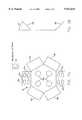
- FIGS. 2A and 2Billustrate a presently preferred embodiment of a satellite antenna for use with the system shown in FIG. 1.
- U.S. patentsteach various aspects of a LEO satellite constellation, and the associated communication system, which may be used in conjunction with the satellite repeater system 10 shown in FIG. 1: U.S. Pat. No. 5,422,647, issued Jun. 6, 1995, entitled “Mobile Communication Satellite Payload”, by E. Hirshfield and C. A. Tsao; U.S. Pat. No. 5,504,493, issued Apr. 2, 1996, entitled “Active Transmit Phased Array Antenna with Amplitude Taper", by E. Hirshfield; U.S. Pat. Nos. 5,448,623, issued Sep. 5, 1995, and 5,526,404, issued Jun.
- the satellite repeater system 10 shown in FIG. 1can be considered as a bi-directional repeater.
- the system 10receives signals from one or more satellites 12 on an omnidirectional antenna 16 and a directional antenna 18 having receive elements 18a, amplifies the received signals, and re-radiates the signals inside of a building in a frequency band suitable for reception by a user terminal (UT) 14.
- the system 10also receives signals transmitted by the UT 14, amplifies the received signals, and transmits the signals with a transmit satellite antenna 20 to the at least one satellite 12.
- the satellite signal that is transmitted to the receive antenna 18is first uplinked from a ground station 13, such as a gateway that is bidirectionally coupled to a terrestrial communications network, such as the public switched telephone network (PSTN). Private networks can also be interface in this manner.
- the signal that is transmitted from the antenna 20 to the satellite 12is downlinked to the ground station 13. In this manner a duplex telephone or data connection can be established between the UT 14 and a telephone, modem, or facsimile device that is connected to the PSTN (or private network).
- the system 10further includes a satellite receiver 22 connected to an output of the omnidirectional receive antenna 16.
- a system controllersuch as a computer 24 is connected to the satellite receiver 22 and with control lines 24a to the directional antenna 18 for controlling the selection and switching of the receive elements 18a, as will be described below.
- a low noise amplifier (LNA) 26is coupled to the receive elements 18a of antenna 18 and provides an amplified receive signal to a splitter 28.
- the splitter 28has a plurality of outputs for distributing the received signal to various locations, such as rooms or floors, within the building. Because of the possibly considerable distances that may be involved, it is preferred to provide a plurality of floor transmit amplifiers 30, individual ones of which have an associated antenna 32.
- each floor of a multi-story buildingwould be provided with at least one floor amplifier 30 and corresponding floor antenna 32.
- the antennas 32transmit the received satellite signals to any UTs 14 within range.
- Also provided on each flooris at least one of a set of UT receive antennas 34 each having an output connected to a floor receive amplifier 36.
- the outputs of the floor receive amplifiersare brought to a central node where a combiner 38 combines the signals into a composite signal 38a that is applied to a transmitter power amplifier (PA) 40, and thence to the satellite transmit antenna 20.
- the LNA 26 and power amplifier 40are also connected to the computer 24 through the control lines 24a whereby the operation of these amplifiers can be varied as required.
- the amplifiers 26 and 34may be variable gain amplifiers that are controlled from the computer 24.
- the UT 14can be a hand-held satellite phone that a user has carried into the building.
- the UT 14may also be a wireless desk-top phone that is adapted for use with the satellites 12.
- the UTs 14are capable of operating in a full duplex mode and communicate via, by example, L-band RF links (uplink or reverse link 14a) and S-band RF links (downlink or forward link 14b).
- the reverse L band RF link 14amay operate within a frequency range of 1.61 GHZ to 1.625 GHZ, a bandwidth of 16.5 MHz, and is modulated with packetized digital voice signals and/or data signals in accordance with a spread spectrum technique.
- the forward S band RF link 14bmay operate within a frequency range of 2.485 GHz to 2.5 GHZ, at a bandwidth of 16.5 MHz.
- Other frequency bandssuch as the new 1.9/2.1 GHz PCS band, and others, may also be employed.
- the UT 14need not be modified for indoor operation. That is, it transmits and receives in the same frequency bands as it would if carried outside, where it would normally communicate directly with one or more of the satellites 12.
- the user terminal 14is operative without modification both within the structure and outside of the structure for communicating with a terrestrial communications network, such as the PSTN, via at least one satellite 12 of the constellation of satellites and the ground station or gateway 13.
- the receive antenna 18is operated to select a single satellite to receive, and places a high-gain beam on that satellite, thereby "capturing" a most favored satellite for communication with one or more UTs 14 inside the building.
- the transmit antenna 20may also have a similar steerable beam, or it can radiate an azimuthally-omnidirectional signal, depending on considerations such as interference.
- a low transmit antenna gaincan be compensated for through the use of a higher power amplifier 22, since the power amplifier 22 can be connected to the power mains in the building. This is not generally possible with the hand-held, portable UT 14, where battery size and life are critical factors for users.
- the ability to select a particular satellite 12, and switch or hand-off between satellites as they change elevation angles with respect to the antenna 18,is an important aspect of this invention.
- the directive nature of the receive antenna 18, and possibly also the transmit antenna 20,enables the system 10 to preferentially select the satellites of one satellite system over others that may be operating in the same frequency band, thereby reducing interference to and from other systems.
- the antenna beam steeringis preferably accomplished by means of the satellite receiver 22 and the computer 24.
- the satellite receiver 22receives and stores time-tagged ephemerides data for all satellites of the desired satellite constellation. Based on this ephemerides data the computer 24 is able to calculate, using well known algorithms, what satellites are visible, and at what elevation angles, at all points in time.
- the computer 24then gives control signals via the control bus 24a to the antenna 18 to steer it to a most desirable satellite, while keeping track of the next satellite(s) which will be rising over the horizon.
- the computer 24switches the antenna beam from one satellite to another. This switching is done in short period of time, and does not disrupt an on-going communication.
- the switch overmay be referred to as a "hard handoff".
- a new communication linkmay be established with the new satellite before terminating the communication link with the current satellite.
- the switch-overin this case may be referred to as a "soft handoff".
- This implementationmay require turning on two beams simultaneously in order to receive signals from two widely-separated satellites.
- the receive antenna 18 illustrated in FIGS. 2A and 2Bis constructed as a switched, flat-plate array.
- Each flat plate 18aproduces a beam in a given direction in elevation and azimuth.
- the various beamsoverlap in order to produce a minimum level of gain in all directions.
- Each beamrejects signals that are outside its coverage area.
- the size and number of beams requiredis determined by how much gain is required in a given direction, and how much rejection is desired in undesired directions. Switching between beams can be accomplished in a short period of time (e.g., a microsecond), resulting on no disruption of the telephone conversations that are ongoing.
- the flat plates 18a of printed-circuit antennascan be replaced by fixed arrays of helices or other circularly-polarized elements, or by a sheet-metal horn antenna with similar radiating properties.
- phased arraythat covers, with reasonable gain, nearly 180° in elevation angle (0°-90°-0°) on a single, flat surface.
- the arrayis constructed with a plurality of flat, canted phased arrays 18b. Individual ones of the plurality of phased arrays point to different sectors of the sky, where each beam steers over its coverage sector, and then the antenna switches to the next beam, which would cover its sector.
- the antenna 18thus constructed provides superior gain and rejection of undesired signals over an antenna having fixed beams.
- both the transmit and receive antennasmay use directional beams which are fixed-pointed to the geostationary satellite. This technique very specifically particularizes the system 10 to the geostationary satellite.
- a simplest implementation within a structure or buildingis comprised of a single unit that contains both the transmit amplifier 40 and the receive amplifier 26, and mounted broad-band antennas 32 and 34 that operate in both frequency bands (i.e., the forward and reverse frequency bands, if they are different).
- the unitpreferably has "visibility" from all portions of the floor or areas that it services in order to provide adequate signals to and from the UTs 14. Depending on the construction and layout of the floors of the building (e.g., placements and numbers of walls and partitions), this arrangement may be difficult to realize.
- Such antennasare known for use in, for example, tunnels, to radiate signals uniformly throughout the length of the tunnel.
- This antenna typeincludes a coaxial cable with a very poor "shield", so that fields radiate from it in a controlled manner. Slots may be periodically cut in the shield to form radiating slot dipoles.
- a cablecan be run in the ceiling at the center of a floor in a building, or around the perimeter of the ceiling to give maximum coverage. If interior wall dividers are non-conducting, the cable antenna can cover the entire floor. If the walls are conducting, the cable may be run into enclosed rooms and offices in order to provide adequate coverage.
- the indoor transmit antennas 32 and amplifiers 30are preferably designed and sized so that the signal radiated indoors is typically not more than about 10 dB above what the UT 14 normally receives directly from the satellite 12. In this case the radiation coming from out-of-doors, assuming typical losses within the building, is substantially lower than what would be received directly from the satellite. This limits interference to the outdoor UTs 14, and allows them to operate as if there was not a system operating inside the building.
- the receive amplifiers 36 and antennas 34are sized and arranged so that signals from UTs 14 outside the building do not penetrate the building and enter the repeater system. If this were to occur, the capacity of the system 10 would be reduced for serving those UTs 14 within the building.
- the placement of the antennas 34is thus a consideration, and they are preferably located away from outside walls. Setting the noise figure of the interior receive amplifiers 34 to a relatively high value also aids in suppressing the reception of outside radiation.
- a leaky coaxial cablecan also be used for the indoor receive function.
- the use of this inventionis also advantageous for those satellite systems that transmit and receive in the same frequency band, and that use time division duplex (TDD).
- TDDtime division duplex
- the receive amplifiers 26 and 34 and the transmit amplifiers 34 and 40all operate at the same frequency, and it is necessary that only one chain of amplification be operating at a time, or the antenna coupling would cause the system to oscillate.
- the control lines 24a connected to the LNA 26 and the power amplifier 40can be used to selectively disable one or the other, depending on the direction of signal flow.
- the satellite receiver 22can be employed to receive signal flow control pulses from the communication signals and to provide the signal timing to the computer 24 for control of the amplifiers 26 and 40.
- the signal propagation within an enclosed spaceresults in multipath propagation and multiple signals arriving at and from the UT 14.
- One conventional technique for dealing with multipathdetects the received signal from more than one antenna, and switches the circuit to the antenna with the strongest signal, thereafter using that antenna for both transmit and receive.
- this techniquewould be suitable for only a single user terminal, as multiple user terminals will have different interference patterns with respect to the antenna.
- CDMA systemsdo not require such tracking and switching, as they use the multipath reflection signals as additional signals, and add them to the primary signal, if such a signal can be identified, using a well known Rake receiver.
- both the UT 14 and the gateway 13employ Rake receivers, as they do in the present system.
- the effects of multipathare minimized through the use of coherent combining techniques.
- Reference in this regardcan be had to the above-mentioned U.S. Pat. No. 5,233,626, issued Aug. 3, 1993, entitled "Repeater Diversity Spread Spectrum Communication System", by S. A. Ames, which describes a Rake receiver used for coherently combining spread spectrum signals.
- the effects of multipathcan be reduced through, by example, the use of known types of adaptive equalization.
- satellite and user terminal transmitted signalsthat are continuous frequency modulated signals.
- the operation of the satellite repeater system 10is completely transparent to the satellite-telephone system, so long as adequate attention is paid to the radiation of the indoor transmitters 32 to the out-of-doors, where they could cause interference to other UTs, as well as the reception by the indoor receivers 36 of out-of-doors UT transmissions.
- the beam of the satellite receive antenna 18is always directed under the control of the computer 24.
- the computer 24has knowledge of the ephemerides of all the satellites 12 of the desired system, as well as the time and date, and is thus enabled to direct the beam to the most favorable satellite that is currently visible.
- the downlink signals 14bare thereby received by the antenna 18, amplified, and re-radiated by antennas 32 inside the building, where they appear to the UT 14 as the satellite signal.
- the UT 14radiates a signal that is detected by the indoor antenna 34, is amplified, and then radiated from the outdoor satellite antenna 20 to the most favored satellite 12.
- the antenna 20may be an omnidirectional or a directional antenna.
- the antenna 20can be constructed in a similar manner to the antenna 18, that is with various transmit elements oriented at some angle and direction with respect to a normal to the surface of the earth. In all cases it is assumed that the antennas 18 and 20 are located so as to be free, if possible, from signal path obstructions due to surrounding buildings, foliage and the like.
- the in-building repeater systemthat is a feature of this invention not only overcomes the loss of signal that is experienced when the satellite signal propagates into the building, but actually improves the signal strength by providing arbitrary amounts of amplifier gain between the satellite signal and the UT signal.
- the signal-to-noise ratio experienced by the UT 14 inside the buildingmay exceed that experienced when operated out-of-doors with a direct line of sight to the satellite 12, because of the UT's lower antenna gain.
- the satellite repeater system 10has been described to provide localized or "cellular" coverage inside buildings for satellite-based communications systems.
- the system 10uses antenna directivity to distinguish between satellite-based systems, and to particularize itself to only a desired system, excluding other systems that may be operating in the same frequency band and with the same modulation scheme.
- the teaching of this inventioncan be employed with any system that is currently licensed in the U.S.A., and any systems that are being anticipated.
- the teaching of this inventionsolves the longstanding problem related to operation deep inside buildings that provide shielding from satellite signals. In other words, it extends the operating range of the user's telephone, or UT 14, to within buildings that would otherwise render the user's terminal inoperative or only marginally operative.
- the user terminal 14 and gateway 13can operate in a normal manner, as when the user terminal 14 is located outside of the building. If a signal received by the gateway 13 is weak, it requests the user terminal 14 to transmit with more power. This is accomplished by periodically transmitting power control bits to the user terminal over the forward link. However, the signal from the user terminal 14 will normally be strong, as it has an arbitrarily strong power amplifier feeding the transmit antenna as part of the indoor repeater.
Landscapes
- Engineering & Computer Science (AREA)
- Physics & Mathematics (AREA)
- Astronomy & Astrophysics (AREA)
- Aviation & Aerospace Engineering (AREA)
- General Physics & Mathematics (AREA)
- Computer Networks & Wireless Communication (AREA)
- Signal Processing (AREA)
- Radio Relay Systems (AREA)
Abstract
Description
Claims (22)
Priority Applications (1)
| Application Number | Priority Date | Filing Date | Title |
|---|---|---|---|
| US08/786,705US5912641A (en) | 1997-01-21 | 1997-01-21 | Indoor satellite cellular repeater system |
Applications Claiming Priority (1)
| Application Number | Priority Date | Filing Date | Title |
|---|---|---|---|
| US08/786,705US5912641A (en) | 1997-01-21 | 1997-01-21 | Indoor satellite cellular repeater system |
Publications (1)
| Publication Number | Publication Date |
|---|---|
| US5912641Atrue US5912641A (en) | 1999-06-15 |
Family
ID=25139368
Family Applications (1)
| Application Number | Title | Priority Date | Filing Date |
|---|---|---|---|
| US08/786,705Expired - LifetimeUS5912641A (en) | 1997-01-21 | 1997-01-21 | Indoor satellite cellular repeater system |
Country Status (1)
| Country | Link |
|---|---|
| US (1) | US5912641A (en) |
Cited By (46)
| Publication number | Priority date | Publication date | Assignee | Title |
|---|---|---|---|---|
| WO2001033738A1 (en)* | 1999-11-01 | 2001-05-10 | Motorola, Inc. | Satellite-based communications system with terrestrial repeater |
| US20010031623A1 (en)* | 2000-03-03 | 2001-10-18 | Lee Masoian | Channel booster amplifier |
| US6334050B1 (en)* | 1997-06-13 | 2001-12-25 | Telefonaktiebolaget Lm Ericsson (Publ) | Arrangement and a method relating to a radio unit |
| US20020041575A1 (en)* | 2000-08-02 | 2002-04-11 | Mobile Satellite Ventures Llc | Coordinated satellite-terrestrial frequency reuse |
| US20020173270A1 (en)* | 2001-03-16 | 2002-11-21 | Buer Kenneth V. | System and method for uplink power control |
| US20030045284A1 (en)* | 2001-09-05 | 2003-03-06 | Copley Richard T. | Wireless communication system, apparatus and method for providing communication service using an additional frequency band through an in-building communication infrastructure |
| US20030104781A1 (en)* | 2001-12-03 | 2003-06-05 | Son O. Sung | Modular residential radio frequency converting repeater |
| US20040038644A1 (en)* | 2002-08-22 | 2004-02-26 | Eagle Broadband, Inc. | Repeater for a satellite phone |
| US6731946B1 (en)* | 2000-11-22 | 2004-05-04 | Ensemble Communications | System and method for timing detector measurements in a wireless communication system |
| US6859652B2 (en) | 2000-08-02 | 2005-02-22 | Mobile Satellite Ventures, Lp | Integrated or autonomous system and method of satellite-terrestrial frequency reuse using signal attenuation and/or blockage, dynamic assignment of frequencies and/or hysteresis |
| US6993287B2 (en) | 2003-03-04 | 2006-01-31 | Four Bars Clarity, Llc | Repeater system for strong signal environments |
| US20060105705A1 (en)* | 2004-11-16 | 2006-05-18 | Andrew Corporation | Consumer installer repeater for wireless communication |
| US20060125684A1 (en)* | 2003-06-10 | 2006-06-15 | Marko Leinonen | Reception of signals in a device comprising a transmitter |
| US20070202804A1 (en)* | 2006-02-28 | 2007-08-30 | Vrd Technologies, Inc. | Satellite signal relay and receiver |
| US20070206666A1 (en)* | 2006-03-01 | 2007-09-06 | Hirschenberger Frank M | Digital satellite receiver and method for expanding digital satellite radio coverage for devices |
| US20080014948A1 (en)* | 2006-07-14 | 2008-01-17 | Lgc Wireless, Inc. | System for and method of for providing dedicated capacity in a cellular network |
| US20080151846A1 (en)* | 2006-12-22 | 2008-06-26 | Stefan Scheinert | System for and method of providing remote coverage area for wireless communications |
| US20080232328A1 (en)* | 2007-03-23 | 2008-09-25 | Stefan Scheinert | Localization of a mobile device in distributed antenna communications system |
| US20090005096A1 (en)* | 2007-06-26 | 2009-01-01 | Stefan Scheinert | Distributed antenna communications system |
| US20090061940A1 (en)* | 2007-08-31 | 2009-03-05 | Stefan Scheinert | System for and method of configuring distributed antenna communications system |
| US7643440B1 (en)* | 2004-03-04 | 2010-01-05 | Rockwell Collins, Inc. | Integrated television and broadband data system for aircraft |
| US20100210209A1 (en)* | 2003-03-24 | 2010-08-19 | Atc Technologies, Llc | Radioterminals and operating methods that receive multiple measures of information from multiple sources |
| US7792488B2 (en) | 2000-12-04 | 2010-09-07 | Atc Technologies, Llc | Systems and methods for transmitting electromagnetic energy over a wireless channel having sufficiently weak measured signal strength |
| US7848770B2 (en) | 2006-08-29 | 2010-12-07 | Lgc Wireless, Inc. | Distributed antenna communications system and methods of implementing thereof |
| US20110140884A1 (en)* | 2009-10-23 | 2011-06-16 | Globalstar, Inc. | Simplex Personal and Asset Tracker |
| US20120094624A1 (en)* | 2009-04-09 | 2012-04-19 | Said Soulhi | Filter for an Indoor Cellular System |
| US8175521B2 (en) | 2003-03-04 | 2012-05-08 | Bandwidth Wireless Limited Liability Company | Repeater system for strong signal environments |
| US20130076567A1 (en)* | 2011-09-26 | 2013-03-28 | Maritime Telecommunications Network, Inc. | Dual antenna transfer switch system, method and apparatus |
| US8655398B2 (en) | 2004-03-08 | 2014-02-18 | Atc Technologies, Llc | Communications systems and methods including emission detection |
| US8676121B1 (en) | 2011-05-31 | 2014-03-18 | Globalstar, Inc. | Method and apparatus for transmitting message from short-range wireless device over a satellite network |
| EP3016300A1 (en)* | 2014-10-30 | 2016-05-04 | Gilat Satcom Ltd. | Indoor satellite communication |
| US20160323032A1 (en)* | 2015-05-01 | 2016-11-03 | Qualcomm Incorporated | Handoff for non-geosynchronous satellite communication |
| CN107094051A (en)* | 2016-12-20 | 2017-08-25 | 南京泰通科技股份有限公司 | The a wide range of optical fiber cladding system in satellite positioning signal blind area and method |
| CN107347190A (en)* | 2017-07-21 | 2017-11-14 | 中国电子科技集团公司第二十九研究所 | A kind of high-speed railway satellite TV signal relay coverage system |
| US9888426B2 (en) | 2015-05-01 | 2018-02-06 | Qualcomm Incorporated | Handoff for satellite communication |
| US9906989B2 (en) | 2012-03-19 | 2018-02-27 | Robert K. Buckle | Apparatus, method and system for integrating mobile and satellite phone service |
| US9927527B2 (en)* | 2015-08-26 | 2018-03-27 | Rockwell Collins, Inc. | Satellite signal acquisition using antennas with beamforming abilities |
| US10009093B2 (en) | 2015-05-01 | 2018-06-26 | Qualcomm Incorporated | Handoff for satellite communication |
| US10045326B2 (en) | 2014-03-07 | 2018-08-07 | Globalstar, Inc. | Cell tower functionality with satellite access to allow a cell device to roam on a satellite network or call forward on a satellite network |
| US20190379446A1 (en)* | 2018-06-06 | 2019-12-12 | Kymeta Corporation | Beam splitting hand off systems architecture |
| US10523160B2 (en) | 2017-08-31 | 2019-12-31 | Wilson Electronics, Llc | Protection of power amplifiers in a signal booster |
| US10873136B1 (en)* | 2019-08-30 | 2020-12-22 | Tionesta, Llc | Methods for formation of antenna array from sub-arrays |
| CN114280647A (en)* | 2021-12-28 | 2022-04-05 | 西安闻泰信息技术有限公司 | Indoor positioning method, device and system, electronic equipment and storage medium |
| CN115085793A (en)* | 2022-06-01 | 2022-09-20 | 陕西天翌科技股份有限公司 | Low-orbit mobile communication satellite tracking device and tracking method |
| US11831392B1 (en)* | 2014-03-15 | 2023-11-28 | Micro Mobio Corporation | Terrestrial and satellite radio frequency transmission system and method |
| US20240146399A1 (en)* | 2022-09-19 | 2024-05-02 | Apple Inc. | Device-Driven Communication Handover |
Citations (5)
| Publication number | Priority date | Publication date | Assignee | Title |
|---|---|---|---|---|
| US5233626A (en)* | 1992-05-11 | 1993-08-03 | Space Systems/Loral Inc. | Repeater diversity spread spectrum communication system |
| US5422647A (en)* | 1993-05-07 | 1995-06-06 | Space Systems/Loral, Inc. | Mobile communication satellite payload |
| US5448623A (en)* | 1991-10-10 | 1995-09-05 | Space Systems/Loral, Inc. | Satellite telecommunications system using network coordinating gateways operative with a terrestrial communication system |
| US5504493A (en)* | 1994-01-31 | 1996-04-02 | Globalstar L.P. | Active transmit phased array antenna with amplitude taper |
| US5552798A (en)* | 1994-08-23 | 1996-09-03 | Globalstar L.P. | Antenna for multipath satellite communication links |
- 1997
- 1997-01-21USUS08/786,705patent/US5912641A/ennot_activeExpired - Lifetime
Patent Citations (6)
| Publication number | Priority date | Publication date | Assignee | Title |
|---|---|---|---|---|
| US5448623A (en)* | 1991-10-10 | 1995-09-05 | Space Systems/Loral, Inc. | Satellite telecommunications system using network coordinating gateways operative with a terrestrial communication system |
| US5526404A (en)* | 1991-10-10 | 1996-06-11 | Space Systems/Loral, Inc. | Worldwide satellite telephone system and a network coordinating gateway for allocating satellite and terrestrial gateway resources |
| US5233626A (en)* | 1992-05-11 | 1993-08-03 | Space Systems/Loral Inc. | Repeater diversity spread spectrum communication system |
| US5422647A (en)* | 1993-05-07 | 1995-06-06 | Space Systems/Loral, Inc. | Mobile communication satellite payload |
| US5504493A (en)* | 1994-01-31 | 1996-04-02 | Globalstar L.P. | Active transmit phased array antenna with amplitude taper |
| US5552798A (en)* | 1994-08-23 | 1996-09-03 | Globalstar L.P. | Antenna for multipath satellite communication links |
Non-Patent Citations (4)
| Title |
|---|
| "Radiating Cable Enhances In-Building And Tunnel Coverage", Dennis J. Burt, Wireless Systems Design, Sep. 1996, (no month). |
| Product description: "Communications Extender (A.C.E.)", Microwave Product Digest, Jun. 1995, p. 38. |
| Product description: Communications Extender (A.C.E.) , Microwave Product Digest, Jun. 1995, p. 38.* |
| Radiating Cable Enhances In Building And Tunnel Coverage , Dennis J. Burt, Wireless Systems Design, Sep. 1996, (no month).* |
Cited By (79)
| Publication number | Priority date | Publication date | Assignee | Title |
|---|---|---|---|---|
| US6334050B1 (en)* | 1997-06-13 | 2001-12-25 | Telefonaktiebolaget Lm Ericsson (Publ) | Arrangement and a method relating to a radio unit |
| WO2001033738A1 (en)* | 1999-11-01 | 2001-05-10 | Motorola, Inc. | Satellite-based communications system with terrestrial repeater |
| US20010031623A1 (en)* | 2000-03-03 | 2001-10-18 | Lee Masoian | Channel booster amplifier |
| US7907893B2 (en) | 2000-08-02 | 2011-03-15 | Atc Technologies, Llc | Integrated or autonomous system and method of satellite-terrestrial frequency reuse using signal attenuation and/or blockage, dynamic assignment of frequencies and/or hysteresis |
| US20020041575A1 (en)* | 2000-08-02 | 2002-04-11 | Mobile Satellite Ventures Llc | Coordinated satellite-terrestrial frequency reuse |
| US8369775B2 (en) | 2000-08-02 | 2013-02-05 | Atc Technologies, Llc | Integrated or autonomous system and method of satellite-terrestrial frequency reuse using signal attenuation and/or blockage, dynamic assignment of frequencies and/or hysteresis |
| US7831251B2 (en) | 2000-08-02 | 2010-11-09 | Atc Technologies, Llc | Integrated or autonomous system and method of satellite-terrestrial frequency reuse using signal attenuation and/or blockage, dynamic assignment of frequencies and/or hysteresis |
| US7706746B2 (en) | 2000-08-02 | 2010-04-27 | Atc Technologies, Llc | Integrated or autonomous system and method of satellite-terrestrial frequency reuse using signal attenuation and/or blockage, dynamic assignment of frequencies and/or hysteresis |
| US6859652B2 (en) | 2000-08-02 | 2005-02-22 | Mobile Satellite Ventures, Lp | Integrated or autonomous system and method of satellite-terrestrial frequency reuse using signal attenuation and/or blockage, dynamic assignment of frequencies and/or hysteresis |
| US6892068B2 (en) | 2000-08-02 | 2005-05-10 | Mobile Satellite Ventures, Lp | Coordinated satellite-terrestrial frequency reuse |
| US7636567B2 (en) | 2000-08-02 | 2009-12-22 | Atc Technologies, Llc | Coordinated satellite-terrestrial frequency reuse |
| US7593726B2 (en) | 2000-08-02 | 2009-09-22 | Atc Technologies, Llc | Coordinated satellite-terrestrial frequency reuse |
| US7577400B2 (en) | 2000-08-02 | 2009-08-18 | Atc Technologies, Llc | Integrated or autonomous system and method of satellite-terrestrial frequency reuse using signal attenuation and/or blockage, dynamic assignment of frequencies and/or hysteresis |
| USRE42225E1 (en) | 2000-11-22 | 2011-03-15 | Harington Valve, Llc | System and method for timing detector measurements in a wireless communication system |
| US6731946B1 (en)* | 2000-11-22 | 2004-05-04 | Ensemble Communications | System and method for timing detector measurements in a wireless communication system |
| US7792488B2 (en) | 2000-12-04 | 2010-09-07 | Atc Technologies, Llc | Systems and methods for transmitting electromagnetic energy over a wireless channel having sufficiently weak measured signal strength |
| US20020173270A1 (en)* | 2001-03-16 | 2002-11-21 | Buer Kenneth V. | System and method for uplink power control |
| US6771930B2 (en)* | 2001-03-16 | 2004-08-03 | U.S. Monolithics, L.L.C. | System and method for uplink power control |
| US20030045284A1 (en)* | 2001-09-05 | 2003-03-06 | Copley Richard T. | Wireless communication system, apparatus and method for providing communication service using an additional frequency band through an in-building communication infrastructure |
| US20030104781A1 (en)* | 2001-12-03 | 2003-06-05 | Son O. Sung | Modular residential radio frequency converting repeater |
| US6996369B2 (en) | 2002-08-22 | 2006-02-07 | Eagle Broadband, Inc. | Repeater for a satellite phone |
| US20040038644A1 (en)* | 2002-08-22 | 2004-02-26 | Eagle Broadband, Inc. | Repeater for a satellite phone |
| US8346158B2 (en) | 2003-03-04 | 2013-01-01 | Bandwidth Wireless Limited Liability Company | Repeater system for strong signal environments |
| US8175521B2 (en) | 2003-03-04 | 2012-05-08 | Bandwidth Wireless Limited Liability Company | Repeater system for strong signal environments |
| US6993287B2 (en) | 2003-03-04 | 2006-01-31 | Four Bars Clarity, Llc | Repeater system for strong signal environments |
| EP2209222A3 (en)* | 2003-03-24 | 2010-10-06 | ATC Technologies, LLC | Satellite assisted push-to-send radioterminal systems and methods |
| US8340592B2 (en) | 2003-03-24 | 2012-12-25 | Atc Technologies, Llc | Radioterminals and operating methods that receive multiple measures of information from multiple sources |
| US20100210209A1 (en)* | 2003-03-24 | 2010-08-19 | Atc Technologies, Llc | Radioterminals and operating methods that receive multiple measures of information from multiple sources |
| US8170474B2 (en) | 2003-03-24 | 2012-05-01 | Atc Technologies, Llc | Satellite assisted radioterminal communications systems and methods |
| US7535413B2 (en)* | 2003-06-10 | 2009-05-19 | Nokia Corporation | Reception of signals in a device comprising a transmitter |
| US20060125684A1 (en)* | 2003-06-10 | 2006-06-15 | Marko Leinonen | Reception of signals in a device comprising a transmitter |
| US7643440B1 (en)* | 2004-03-04 | 2010-01-05 | Rockwell Collins, Inc. | Integrated television and broadband data system for aircraft |
| US8655398B2 (en) | 2004-03-08 | 2014-02-18 | Atc Technologies, Llc | Communications systems and methods including emission detection |
| US20060105705A1 (en)* | 2004-11-16 | 2006-05-18 | Andrew Corporation | Consumer installer repeater for wireless communication |
| US20070202804A1 (en)* | 2006-02-28 | 2007-08-30 | Vrd Technologies, Inc. | Satellite signal relay and receiver |
| US20070206666A1 (en)* | 2006-03-01 | 2007-09-06 | Hirschenberger Frank M | Digital satellite receiver and method for expanding digital satellite radio coverage for devices |
| US7844273B2 (en) | 2006-07-14 | 2010-11-30 | Lgc Wireless, Inc. | System for and method of for providing dedicated capacity in a cellular network |
| US20080014948A1 (en)* | 2006-07-14 | 2008-01-17 | Lgc Wireless, Inc. | System for and method of for providing dedicated capacity in a cellular network |
| US7848770B2 (en) | 2006-08-29 | 2010-12-07 | Lgc Wireless, Inc. | Distributed antenna communications system and methods of implementing thereof |
| US7817958B2 (en) | 2006-12-22 | 2010-10-19 | Lgc Wireless Inc. | System for and method of providing remote coverage area for wireless communications |
| US20080151846A1 (en)* | 2006-12-22 | 2008-06-26 | Stefan Scheinert | System for and method of providing remote coverage area for wireless communications |
| US8005050B2 (en) | 2007-03-23 | 2011-08-23 | Lgc Wireless, Inc. | Localization of a mobile device in distributed antenna communications system |
| US20080232328A1 (en)* | 2007-03-23 | 2008-09-25 | Stefan Scheinert | Localization of a mobile device in distributed antenna communications system |
| USRE45505E1 (en) | 2007-03-23 | 2015-05-05 | Adc Telecommunications, Inc. | Localization of a mobile device in distributed antenna communications system |
| US8010116B2 (en) | 2007-06-26 | 2011-08-30 | Lgc Wireless, Inc. | Distributed antenna communications system |
| US8229497B2 (en) | 2007-06-26 | 2012-07-24 | Lgc Wireless, Llc | Distributed antenna communications system |
| US20090005096A1 (en)* | 2007-06-26 | 2009-01-01 | Stefan Scheinert | Distributed antenna communications system |
| US8532698B2 (en) | 2007-06-26 | 2013-09-10 | Adc Telecommunications, Inc. | Distributed antenna communications system |
| US9112547B2 (en) | 2007-08-31 | 2015-08-18 | Adc Telecommunications, Inc. | System for and method of configuring distributed antenna communications system |
| US20090061940A1 (en)* | 2007-08-31 | 2009-03-05 | Stefan Scheinert | System for and method of configuring distributed antenna communications system |
| US20120094624A1 (en)* | 2009-04-09 | 2012-04-19 | Said Soulhi | Filter for an Indoor Cellular System |
| US8666345B2 (en)* | 2009-04-09 | 2014-03-04 | Telefonaktiebolaget L M Ericsson (Publ) | Filter for an indoor cellular system |
| US8604925B2 (en) | 2009-10-23 | 2013-12-10 | Globalstar, Inc. | Simplex personal and asset tracker |
| US20110140884A1 (en)* | 2009-10-23 | 2011-06-16 | Globalstar, Inc. | Simplex Personal and Asset Tracker |
| US8676121B1 (en) | 2011-05-31 | 2014-03-18 | Globalstar, Inc. | Method and apparatus for transmitting message from short-range wireless device over a satellite network |
| US20130076567A1 (en)* | 2011-09-26 | 2013-03-28 | Maritime Telecommunications Network, Inc. | Dual antenna transfer switch system, method and apparatus |
| US8730103B2 (en)* | 2011-09-26 | 2014-05-20 | MTN Satellite Communications | Dual antenna transfer switch system, method and apparatus |
| US9431701B1 (en)* | 2011-09-26 | 2016-08-30 | Emc Satcom Technologies Llc | Dual antenna transfer switch system, method and apparatus |
| US9906989B2 (en) | 2012-03-19 | 2018-02-27 | Robert K. Buckle | Apparatus, method and system for integrating mobile and satellite phone service |
| US10045326B2 (en) | 2014-03-07 | 2018-08-07 | Globalstar, Inc. | Cell tower functionality with satellite access to allow a cell device to roam on a satellite network or call forward on a satellite network |
| US11831392B1 (en)* | 2014-03-15 | 2023-11-28 | Micro Mobio Corporation | Terrestrial and satellite radio frequency transmission system and method |
| EP3016300A1 (en)* | 2014-10-30 | 2016-05-04 | Gilat Satcom Ltd. | Indoor satellite communication |
| US20160323032A1 (en)* | 2015-05-01 | 2016-11-03 | Qualcomm Incorporated | Handoff for non-geosynchronous satellite communication |
| US9762314B2 (en)* | 2015-05-01 | 2017-09-12 | Qualcomm Incorporated | Handoff for non-geosynchronous satellite communication |
| US9888426B2 (en) | 2015-05-01 | 2018-02-06 | Qualcomm Incorporated | Handoff for satellite communication |
| US10009093B2 (en) | 2015-05-01 | 2018-06-26 | Qualcomm Incorporated | Handoff for satellite communication |
| US9927527B2 (en)* | 2015-08-26 | 2018-03-27 | Rockwell Collins, Inc. | Satellite signal acquisition using antennas with beamforming abilities |
| CN107094051A (en)* | 2016-12-20 | 2017-08-25 | 南京泰通科技股份有限公司 | The a wide range of optical fiber cladding system in satellite positioning signal blind area and method |
| CN107347190A (en)* | 2017-07-21 | 2017-11-14 | 中国电子科技集团公司第二十九研究所 | A kind of high-speed railway satellite TV signal relay coverage system |
| US10523160B2 (en) | 2017-08-31 | 2019-12-31 | Wilson Electronics, Llc | Protection of power amplifiers in a signal booster |
| US20190379446A1 (en)* | 2018-06-06 | 2019-12-12 | Kymeta Corporation | Beam splitting hand off systems architecture |
| US11063661B2 (en)* | 2018-06-06 | 2021-07-13 | Kymeta Corporation | Beam splitting hand off systems architecture |
| US11411640B2 (en)* | 2018-06-06 | 2022-08-09 | Kymeta Corporation | Beam splitting hand off systems architecture |
| US11870544B2 (en) | 2018-06-06 | 2024-01-09 | Kymeta Corporation | Beam splitting hand off systems architecture |
| US10873136B1 (en)* | 2019-08-30 | 2020-12-22 | Tionesta, Llc | Methods for formation of antenna array from sub-arrays |
| CN114280647A (en)* | 2021-12-28 | 2022-04-05 | 西安闻泰信息技术有限公司 | Indoor positioning method, device and system, electronic equipment and storage medium |
| CN115085793A (en)* | 2022-06-01 | 2022-09-20 | 陕西天翌科技股份有限公司 | Low-orbit mobile communication satellite tracking device and tracking method |
| CN115085793B (en)* | 2022-06-01 | 2023-10-17 | 陕西天翌科技股份有限公司 | Low-orbit mobile communication satellite tracking device and tracking method |
| US20240146399A1 (en)* | 2022-09-19 | 2024-05-02 | Apple Inc. | Device-Driven Communication Handover |
Similar Documents
| Publication | Publication Date | Title |
|---|---|---|
| US5912641A (en) | Indoor satellite cellular repeater system | |
| JP3748632B2 (en) | A system for transmitting radio signals via geostationary communication satellites | |
| US5485485A (en) | Radio frequency broadcasting systems and methods using two low-cost geosynchronous satellites and hemispherical coverage antennas | |
| US6314305B1 (en) | Transmitter/receiver for combined adaptive array processing and fixed beam switching | |
| Godara | Applications of antenna arrays to mobile communications. I. Performance improvement, feasibility, and system considerations | |
| JP2763099B2 (en) | Spread spectrum multiple access communication system using satellite or remote repeater. | |
| CN107623538B (en) | Phased array radio frequency network for mobile communications | |
| US5552798A (en) | Antenna for multipath satellite communication links | |
| US9917635B2 (en) | Distributed SATCOM aperture on fishing boat | |
| JP7592853B2 (en) | Beam forming system and technique for switching satellite operating modes | |
| KR20050098028A (en) | Method and system for improving communication | |
| CN103636143A (en) | Spectrum sharing between aircraft-based space-ground communication systems and existing geostationary satellite services | |
| JPS6220743B2 (en) | ||
| US6275482B1 (en) | Combined angular, spatial, and temporal diversity for mobile radio system | |
| AU2020102544A4 (en) | PCML- Movable Satellite: Propagation Impairments for Movable Satellite Communication Links at The Microwave Frequencies in Defined Location | |
| EA000972B1 (en) | A mobile-link system for a radio communication system with diversity reception of selected uplink signals for transmitting downlink signals | |
| AU2020102827A4 (en) | IPCM- Movable Satellite: Intelligent Propagation Impairments for Movable Satellite Communication Links at The Microwave Frequencies in Location | |
| Egami | A power-sharing multiple-beam mobile satellite in Ka band | |
| CA2336757C (en) | Communication system utilizing multiple satellites without intersatellite crosslinks | |
| US11588542B2 (en) | System and method for improving link performance with ground based beam former | |
| JP2007324960A (en) | Satellite communication method and apparatus | |
| Tategami et al. | Proposal of ultra long-range wide-area massive MIMO for high-capacity feeder links in satellite communications | |
| JP2002232335A (en) | Diversity satellite broadcast receiving system and device | |
| Barton et al. | Future mobile satellite communication concepts at 20/30 GHz | |
| Demirev | SCP-RPSC–the Key Technology for the Next Generation Microwave Communication Systems |
Legal Events
| Date | Code | Title | Description |
|---|---|---|---|
| AS | Assignment | Owner name:GLOBALSTAR L.P., CALIFORNIA Free format text:ASSIGNMENT OF ASSIGNORS INTEREST;ASSIGNOR:DIETRICH, FREDERICK J.;REEL/FRAME:009707/0842 Effective date:19970120 | |
| FEPP | Fee payment procedure | Free format text:PAYOR NUMBER ASSIGNED (ORIGINAL EVENT CODE: ASPN); ENTITY STATUS OF PATENT OWNER: LARGE ENTITY | |
| STCF | Information on status: patent grant | Free format text:PATENTED CASE | |
| FPAY | Fee payment | Year of fee payment:4 | |
| AS | Assignment | Owner name:GLOBALSTAR LLC, CALIFORNIA Free format text:ASSIGNMENT OF ASSIGNORS INTEREST;ASSIGNOR:GLOBALSTAR L.P.;REEL/FRAME:017154/0960 Effective date:20051222 | |
| AS | Assignment | Owner name:GLOBALSTAR, INC.,CALIFORNIA Free format text:ASSIGNMENT OF ASSIGNORS INTEREST;ASSIGNOR:GLOBALSTAR LLC;REEL/FRAME:017870/0117 Effective date:20060623 Owner name:GLOBALSTAR, INC., CALIFORNIA Free format text:ASSIGNMENT OF ASSIGNORS INTEREST;ASSIGNOR:GLOBALSTAR LLC;REEL/FRAME:017870/0117 Effective date:20060623 | |
| AS | Assignment | Owner name:WACHOVIA INVESTMENT HOLDINGS, LLC,NORTH CAROLINA Free format text:PATENT SECURITY AGREEMENT;ASSIGNOR:GLOBALSTAR, INC.;REEL/FRAME:017982/0148 Effective date:20060421 Owner name:WACHOVIA INVESTMENT HOLDINGS, LLC, NORTH CAROLINA Free format text:PATENT SECURITY AGREEMENT;ASSIGNOR:GLOBALSTAR, INC.;REEL/FRAME:017982/0148 Effective date:20060421 | |
| FPAY | Fee payment | Year of fee payment:8 | |
| AS | Assignment | Owner name:THERMO FUNDING COMPANY LLC, COLORADO Free format text:ASSIGNMENT OF CREDIT AGREEMENT;ASSIGNOR:WACHOVIA INVESTMENT HOLDINGS, LLC;REEL/FRAME:020353/0683 Effective date:20071217 Owner name:THERMO FUNDING COMPANY LLC,COLORADO Free format text:ASSIGNMENT OF CREDIT AGREEMENT;ASSIGNOR:WACHOVIA INVESTMENT HOLDINGS, LLC;REEL/FRAME:020353/0683 Effective date:20071217 | |
| AS | Assignment | Owner name:GLOBALSTAR, INC., CALIFORNIA Free format text:RELEASE BY SECURED PARTY;ASSIGNOR:THERMO FUNDING COMPANY LLC;REEL/FRAME:022856/0094 Effective date:20090622 Owner name:GLOBALSTAR, INC.,CALIFORNIA Free format text:RELEASE BY SECURED PARTY;ASSIGNOR:THERMO FUNDING COMPANY LLC;REEL/FRAME:022856/0094 Effective date:20090622 | |
| AS | Assignment | Owner name:BNP PARIBAS, FRANCE Free format text:GRANT OF SECURITY INTEREST;ASSIGNOR:GLOBALSTAR, INC.;REEL/FRAME:022856/0308 Effective date:20090622 Owner name:BNP PARIBAS,FRANCE Free format text:GRANT OF SECURITY INTEREST;ASSIGNOR:GLOBALSTAR, INC.;REEL/FRAME:022856/0308 Effective date:20090622 | |
| FPAY | Fee payment | Year of fee payment:12 | |
| AS | Assignment | Owner name:GLOBALSTAR, INC., LOUISIANA Free format text:RELEASE BY SECURED PARTY;ASSIGNOR:BNP PARIBAS;REEL/FRAME:058220/0028 Effective date:20211108 |