US5912534A - Double relay light switching system for providing daytime running lights for vehicles - Google Patents
Double relay light switching system for providing daytime running lights for vehiclesDownload PDFInfo
- Publication number
- US5912534A US5912534AUS08/819,042US81904297AUS5912534AUS 5912534 AUS5912534 AUS 5912534AUS 81904297 AUS81904297 AUS 81904297AUS 5912534 AUS5912534 AUS 5912534A
- Authority
- US
- United States
- Prior art keywords
- relay
- vehicle
- switch
- primary
- power
- Prior art date
- Legal status (The legal status is an assumption and is not a legal conclusion. Google has not performed a legal analysis and makes no representation as to the accuracy of the status listed.)
- Expired - Lifetime
Links
- 239000007858starting materialSubstances0.000claimsabstractdescription47
- 230000004913activationEffects0.000description13
- 230000001012protectorEffects0.000description7
- 230000005540biological transmissionEffects0.000description6
- 230000001276controlling effectEffects0.000description6
- 230000004048modificationEffects0.000description5
- 238000012986modificationMethods0.000description5
- 238000010586diagramMethods0.000description4
- 238000005286illuminationMethods0.000description4
- 238000012544monitoring processMethods0.000description3
- 230000003213activating effectEffects0.000description2
- PCHJSUWPFVWCPO-UHFFFAOYSA-NgoldChemical compound[Au]PCHJSUWPFVWCPO-UHFFFAOYSA-N0.000description2
- 239000010931goldSubstances0.000description2
- 229910052737goldInorganic materials0.000description2
- KJBWWVTTZNVMKW-LPYMAVHISA-N1-(dipyridin-2-ylmethylideneamino)-3-[(E)-(2-hydroxyphenyl)methylideneamino]thioureaChemical compoundOc1ccccc1\C=N\N\C([S-])=[NH+]/N=C(c1ccccn1)c1ccccn1KJBWWVTTZNVMKW-LPYMAVHISA-N0.000description1
- 240000000662Anethum graveolensSpecies0.000description1
- 230000001934delayEffects0.000description1
- 230000001419dependent effectEffects0.000description1
- 238000000034methodMethods0.000description1
- 230000001681protective effectEffects0.000description1
- 230000001105regulatory effectEffects0.000description1
Images


Classifications
- B—PERFORMING OPERATIONS; TRANSPORTING
- B60—VEHICLES IN GENERAL
- B60Q—ARRANGEMENT OF SIGNALLING OR LIGHTING DEVICES, THE MOUNTING OR SUPPORTING THEREOF OR CIRCUITS THEREFOR, FOR VEHICLES IN GENERAL
- B60Q1/00—Arrangement of optical signalling or lighting devices, the mounting or supporting thereof or circuits therefor
- B60Q1/02—Arrangement of optical signalling or lighting devices, the mounting or supporting thereof or circuits therefor the devices being primarily intended to illuminate the way ahead or to illuminate other areas of way or environments
- B60Q1/04—Arrangement of optical signalling or lighting devices, the mounting or supporting thereof or circuits therefor the devices being primarily intended to illuminate the way ahead or to illuminate other areas of way or environments the devices being headlights
- B60Q1/14—Arrangement of optical signalling or lighting devices, the mounting or supporting thereof or circuits therefor the devices being primarily intended to illuminate the way ahead or to illuminate other areas of way or environments the devices being headlights having dimming means
- B60Q1/1415—Dimming circuits
- B60Q1/1423—Automatic dimming circuits, i.e. switching between high beam and low beam due to change of ambient light or light level in road traffic
- B60Q1/143—Automatic dimming circuits, i.e. switching between high beam and low beam due to change of ambient light or light level in road traffic combined with another condition, e.g. using vehicle recognition from camera images or activation of wipers
- B—PERFORMING OPERATIONS; TRANSPORTING
- B60—VEHICLES IN GENERAL
- B60Q—ARRANGEMENT OF SIGNALLING OR LIGHTING DEVICES, THE MOUNTING OR SUPPORTING THEREOF OR CIRCUITS THEREFOR, FOR VEHICLES IN GENERAL
- B60Q1/00—Arrangement of optical signalling or lighting devices, the mounting or supporting thereof or circuits therefor
- B60Q1/02—Arrangement of optical signalling or lighting devices, the mounting or supporting thereof or circuits therefor the devices being primarily intended to illuminate the way ahead or to illuminate other areas of way or environments
- B60Q1/04—Arrangement of optical signalling or lighting devices, the mounting or supporting thereof or circuits therefor the devices being primarily intended to illuminate the way ahead or to illuminate other areas of way or environments the devices being headlights
- B60Q1/14—Arrangement of optical signalling or lighting devices, the mounting or supporting thereof or circuits therefor the devices being primarily intended to illuminate the way ahead or to illuminate other areas of way or environments the devices being headlights having dimming means
- B60Q1/1415—Dimming circuits
- B60Q1/1423—Automatic dimming circuits, i.e. switching between high beam and low beam due to change of ambient light or light level in road traffic
- B—PERFORMING OPERATIONS; TRANSPORTING
- B60—VEHICLES IN GENERAL
- B60Q—ARRANGEMENT OF SIGNALLING OR LIGHTING DEVICES, THE MOUNTING OR SUPPORTING THEREOF OR CIRCUITS THEREFOR, FOR VEHICLES IN GENERAL
- B60Q2300/00—Indexing codes for automatically adjustable headlamps or automatically dimmable headlamps
- B60Q2300/05—Special features for controlling or switching of the light beam
- B60Q2300/052—Switching delay, i.e. the beam is not switched or changed instantaneously upon occurrence of a condition change
- B—PERFORMING OPERATIONS; TRANSPORTING
- B60—VEHICLES IN GENERAL
- B60Q—ARRANGEMENT OF SIGNALLING OR LIGHTING DEVICES, THE MOUNTING OR SUPPORTING THEREOF OR CIRCUITS THEREFOR, FOR VEHICLES IN GENERAL
- B60Q2300/00—Indexing codes for automatically adjustable headlamps or automatically dimmable headlamps
- B60Q2300/20—Indexing codes relating to the driver or the passengers
- B60Q2300/21—Manual control
- B—PERFORMING OPERATIONS; TRANSPORTING
- B60—VEHICLES IN GENERAL
- B60Q—ARRANGEMENT OF SIGNALLING OR LIGHTING DEVICES, THE MOUNTING OR SUPPORTING THEREOF OR CIRCUITS THEREFOR, FOR VEHICLES IN GENERAL
- B60Q2400/00—Special features or arrangements of exterior signal lamps for vehicles
- B60Q2400/30—Daytime running lights [DRL], e.g. circuits or arrangements therefor
Definitions
- This inventionis generally directed to automatic circuits for providing automatic daytime running lights (DRL) for automotive vehicles and, more particularly, to a double relay switch system for providing DRL whenever a vehicle ignition switch is ON and a starter switch is OFF and dependent upon the condition of manual overrides, ambient condition sensors and vehicle condition sensors.
- DRLdaytime running lights
- DRLAutomatic headlight and daytime running light
- Such systemsare designed to provide illumination of vehicle headlights and, in some cases, parking or taillights and ICC trailer running lights for purposes of improving the manner in which a vehicle is made conspicuous in the daytime to thereby increase safety.
- Some existing systemsprovide for energizing the high beam filaments of the vehicle headlights at reduced power and others energize the lowbeam filaments of the headlights at normal power.
- the vehicle circuitincludes a manual switch for activating the vehicle exterior lighting system with such protective circuits only being activated or useful in the event the manual switch is in the ON condition.
- the present inventionis directed to a double relay circuit for providing an automatic daytime running light (DRL) system for vehicles which includes at least one first or primary normally open relay positioned between the vehicle power supply and the vehicle ignition and starter switches so as to control power to either the vehicle headlights and/or taillights and ICC running lights whenever the ignition is in an ON condition and the starter switch is in an OFF condition subject to override controls relating to manual switches and ambient condition and automotive condition sensors which automatically extinguish the DRL circuit.
- DRLdaytime running light
- the primary relayhas an input connected to the ignition switch and is connected to ground through a secondary relay which has an input connected to the starter switch, whereby when the starter switch is activated, the secondary relay opens to ground and that the primary relay switch is also open to ground, thereby preventing operation of the DRL system and extinguishing power through the at least one primary relay.
- a time delay switchmay be provided either between the vehicle power supply or the ignition switch and the primary relay(s) so that the primary relay(s) cannot function until a predetermined time after the ignition switch is turned to an ON condition.
- the double relay control systemis deactivated so that full power may be applied through the vehicle dimmer switch to the headlights, parking, tail and running lights.
- the double relay systemis disclosed in combination with various ambient condition sensors such as moisture sensors and light sensors which are operative to override and deactivate the double relay control system in the event ambient conditions are sensed.
- the double relay control systemis interfaced with vehicle condition sensors which monitor such things as the transmission to determine if the transmission is in "PARK" or to sense the position of the emergency brake, whereby if the emergency brake is applied or if the vehicle transmission is in "PARK," the double relay control system is deactivated to prevent power from being supplied therethrough to the exterior lighting system of the vehicle.
- the primary relayincludes a pair of moveable contacts, each being connected to an output to one of either of the vehicle headlights or the vehicle parking, tail or ICC running lights.
- the ignition switch and with the starter switch being OFFpower is supplied through the separate contacts to the vehicle headlights and the vehicle parking, tail and ICC running lights.
- a pair of primary relaysare connected between the power supply and the exterior vehicle lights with one having an output to the vehicle headlights and the other having an output to the vehicle parking, tail and/or ICC running lights.
- the first and second primary relaysare interconnected with one another to the common ground established by the secondary relay.
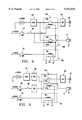
- FIG. 1is a simplified circuit diagram illustrating the double relay control system of the present invention
- FIG. 2is a modification to the circuit diagram to FIG. 1 incorporating a time delay in the control circuit
- FIG. 3is a further modification of the circuit of FIG. 1 showing a time delay in another portion of the control circuit
- FIG. 4is a circuit diagram illustrating the double relay control system of the present invention utilizing a two position switch relay in a relay circuit similar to FIG. 1;
- FIG. 5is a further modification of the circuit of FIG. 1 incorporating a DPST relay for simultaneously controlling the operation of the headlights and parking lights;
- FIG. 6is a circuit diagram incorporating the control system of FIG. 1 in a daytime running light (DRL) circuit
- FIG. 7is the control circuit of FIG. 1 incorporated with both a daytime running light (DRL) system and an ambient condition sensing system.
- DRLdaytime running light
- the double relay control circuits of the present inventionare designed to supply power to the vehicle headlights 10, parking, tail or running lights 11, whenever the ignition switch 12 is in the ON position and the starter switch is in the OFF position.
- a first or primary normally open relay 15consists of a movable contact 16 and coil 17 .
- the movable contactis connected to the vehicle 12 volt DC power supply or battery “B” through a current overload protector (COP) 18 which may be a fuse, thermally activated switch or contacts, or any other conventional overload protector.
- COPcurrent overload protector
- the first or primary relay 15is connected through a second normally closed relay 22 to ground. Therefore, whenever the relay 22 is open, power through the primary relay is automatically terminated.
- Relay 22includes a normally closed movable contact 23 which is urged into an open position upon activation of a related relay coil 24 which receives power through the starter switch 13 when the starter switch is in a closed position to activate the starter motor.
- a related relay coil 24which receives power through the starter switch 13 when the starter switch is in a closed position to activate the starter motor.
- An optional normally closed manual by-pass or cut-off switch 25may be included and placed between the ignition switch and the coil 17 of the first relay 15 to manually turn OFF the lights. This feature is particular advantageous for military uses or utility uses when the engine must be operated without the lights being on. Therefore, by opening the manual switch 25, even though the ignition switch is ON, the lighting system is de-energized.
- a time delay ON/OFF switch 26is provided between the current overload protector and the movable contact of the first relay 15.
- the time delay ON/OFFis designed to maintain the lights OFF until the engine is running.
- the time delay switchcan be placed between the power supply and the lights, as is shown in FIG. 2, or may be placed between the ignition switch 12 and the coil 17 of the first relay, as is shown in FIG. 3. In actual practice, the time delay switch can be placed anywhere in the first relay coil circuit.
- the time delaycan also control the OFF time after the ignition switch is de-activated so that power is only supplied to the exterior vehicle lights for a predetermined period after the ignition is OFF.
- FIG. 4a modification of the circuitry of FIGS. 1-3 is disclosed wherein separate primary relays are provided for controlling the operation of the headlights 10 and tail, parking or running lights 11.
- the first primary relay 15 of FIG. 1has been replaced by a pair of relays 15A and 15B each of which is normally open and includes a movable contact 16A, 16B which is activated by a coil 17A, 17B.
- Both of the movable contacts 16A and 16Bare connected through the current overload protector 18 to the vehicle power supply and movable contact 16A is also connected through the vehicle dimmer switch 20 to the vehicle headlights 10.
- the movable contact 16Bis connected directly to the vehicle parking, tail or running lights 11.
- Coils 17A and 17Bare connected to the ignition switch 12 through an optional manual override switch 25 so that coil 17A and 17B are activated whenever the ignition switch is ON and the manual switched is closed. Both of the coils 17A and 17B are connected to ground through a normally closed movable contact 23 of relay 22. Secondary relay 22 also includes an activation coil 24 connected to the vehicles starter switch 13. Therefore, whenever the starter switch is in a closed or ON position to activate the starter motor, power to the coils 17A and 17B will be terminated as the movable contact 23 will be open thereby disconnecting the coils 17A and 17B from ground and terminating power to the headlights and other exterior lights. The same time delays disclosed in FIGS. 2 and 3 may also be utilized with the circuitry of FIG. 4.
- FIG. 5A further embodiment to the control circuitry of FIG. 1 is shown in FIG. 5 wherein the primary relay 15 has been replaced by a double pole relay switch 15C including interconnected movable contacts 16C and 16C' which are simultaneously activated by coil 17C which is connected to the vehicle ignition switch 12 through an optional normally closed manual override switch 25.
- Movable contact 16Cis connected through the vehicle dimmer switch 20 to the headlights 10 whereas movable contact 16C' is connected directly to the vehicle taillights, parking lights and clearance or running lights 11.
- the movable contacts 16C and 16C'are connected through a current overload protector 18 to the vehicle power supply and may be connected through a time delay 26, as previously described.
- Relay coil 17Cis connected to ground through the normally closed movable contact 23 of the secondary relay 22.
- Coil 24is connected to the vehicle starter switch 13 so that whenever the starter switch is activated the normally closed contact 23 will be open thereby extinguishing power to the coil 17C of relay 15C and extinguishing power to the vehicle lights 10 and 11.
- the time delay 26may optionally be placed in the circuit between the ignition switch and the coil 17C.
- the double relay control system of the present inventionis shown in a circuit to supply power at a reduced level to the high beam filaments 10' whenever the ignition switch 12 is ON and the starter switch 13 is OFF or open.
- DRLdaytime running light
- Power at a reduced levelis applied in the DRL circuit to the high beam filaments 10' by connecting the filaments to the vehicle power supply through a primary relay 15.
- Movable contact 16which is normally open is connected through a current overload protector 18 to the vehicle power supply and is also connected through a Zener diode Z1 to the high beam filament 10'.
- the Zener diodefunctions to reduce the power to an appropriate level so as to illuminate the high beam filaments at a reduced level and thereby prolong the life of the high beam filament.
- Movable contact 16 of relay 15is closed by activation of coil 17 which is connected to the vehicle ignition switch 12.
- An optional manual override switch 25 and time delay switch 26may be provided as previously discussed to further control power through the primary relay 15.
- Coil 17is connected to ground through normally closed contact 23 of relay 22. Normally closed contact 23 is open by activation of coil 24 whenever the vehicle starter switch 13 is activated to provide power to the starter motor. This automatically ensures that all power to the vehicle headlights and taillights is terminated at relay 15 whenever the starter motor is engaged.
- Relay 15is further connected through the vehicle dimmer switch 20 to the low beam filaments 10" and may optionally be connected to activate the vehicle parking, tail or running lights 11, as shown in dotted line in FIG. 6, wherever the coil 17 is activated.
- the low beam filamentsmay be powered at either a reduced power level or full power level.
- the relayswould function in the same manner as described for regulating power to the high beam filaments in a DRL mode.
- the conventional vehicle light switch 14is connected directly to the vehicle parking, tail or running lights 11 and through a diode D3 to the vehicle dimmer switch 20 and from there to the vehicle headlights 10' and 10". It is necessary to override the DRL power supply to the high beam filament 10', or power to the low beam filament, in a DRL mode, in the event the conventional light switch 14 is activated. To accomplish this, whenever the manual light switch is ON, voltage is applied to the coil 24 of relay 22 opening the movable contact 23 to thereby terminate power to the coil 17 of relay 15. By de-energizing the coil 17 of relay 15, the relay is open thereby turning OFF the high beam headlights at reduced power through Zener diode Z1.
- optional or alternative power to the tail, parking and running lights, and/or the low beam headlight filaments, as shown in dotted line in FIG. 6,is also extinguished through relay 15 and power is applied directly through the vehicle light switch 14 to the exterior vehicle lights including headlights and taillights.
- a diode D1is placed between the starter switch 13 and the junction of the circuit from the light switch 14 to the coil 24 of relay 22 so that the light switch activation does not activate the starter.
- Diode D2is placed between the light switch circuit and the junction of the light switch circuit to the starter motor switch 13 so that when the starter switch is activated the normal manual light switch is not activated.
- the diode D3is placed ahead of the input side of the dimmer switch 20 to prevent back feed voltage from the high beam headlights, during the DRL operation, into the light switch circuit to thus preventing the high beam DRL activation from activating relay 22 and causing the lights to flash ON and OFF.
- the time delay 26may be placed in the circuit between the ignition switch 12 and the coil 17 of relay 15 to delay the activation of relay 15 until the starter switch is activated. This will prevent the lights from coming ON until after the starter switch has been released.
- the manual override switch 25may be placed between the ignition switch 12 and the coil 17 of relay 15 to manually extinguish power to the lights at a time when it is necessary to allow continued vehicle operation without lights. It should be noted that the relay configurations shown in FIGS. 4 and 5 may also be used.
- the double relay control circuitry of the present inventionis shown in further combination with sensors for controlling the activation of the exterior vehicle lights including headlights and taillights depending upon various ambient conditions, such as the presence of moisture or the reduction of light levels.
- the control of the headlights during the DRL operation of the systemis the same as described with respect to FIGS. 6 with the optional control of the taillights in the DRL mode being shown in dotted line in the drawing figure.
- the double relay configurations of FIGS. 4 and 5may also be used.
- a power take off circuit line 30is connected between the current overload protector 18 and the input to the movable contact 16 of relay 15.
- Line 30is connected to a light sensor (LS) 31 and a moisture sensor (MS) 32 the outputs of which are connected to a coil 33 of a third relay 35.
- Relay 35includes a normally open movable contact 36 which is moved to a closed position upon the activation of either the light sensor 31 or moisture sensor 32 determining a low light level or the presence of moisture.
- coil 33is activated thereby closing the contact 36 and providing power from the power supply directly to the vehicle parking lights, taillights and running lights 11 and to the vehicle headlights 10' and 10" through diode D3 and the dimmer switch 20.
- switch 35is also shown as being connected through diode D2 to the coil 24 of relay 22. Therefore, whenever the power is being supplied to the dimmer switch 20 and to the parking, tail or running lights 11 by activation of the relay 35, relay 22 will be caused to open thereby terminating power to coil 17 of relay 15 and thus de-activating the power supply through Zener diode Z1 in the DRL mode to the vehicle headlights and optional parking lights 11.
- a separate automotive condition sensormay be provided for monitoring activation of the vehicle windshield wiper circuit 40 (WW), as shown in dotted line in FIG. 7. Whenever the windshield wiper motor(s) is activated, power will be supplied to coil 33 of relay 35 thereby closing contact 36 and extinguishing the DRL mode of light power supply.
- the relay control circuit of the present inventionmay also be utilized in combination with control sensors for monitoring other specific conditions of the vehicle so that power in the DRL mode is prevented even when the ignition switch 12 is ON and the starter motor switch 13 is OFF. In some instances, automatic illumination of the vehicle exterior lights may not be desired, such as when the vehicle is parked or when the emergency brake is applied.
- a sensor (TP) 42may be associated with the vehicle transmission which is operable to supply current to coil 23 of relay 35 when the transmission is placed in "PARK.” A sensed position of the transmission lever or control will therefore override the DRL operation of the lighting system.
- a sensor (PB) 45may be incorporated with the vehicle parking brake to provide power to the coil 33 of relay 35 whenever the parking brake is engaged to thereby override the DRL operation of the lighting system.
- ACSambient condition sensors
- VCSvehicle condition sensors
Landscapes
- Engineering & Computer Science (AREA)
- Mechanical Engineering (AREA)
- Lighting Device Outwards From Vehicle And Optical Signal (AREA)
Abstract
Description
This application is related to provisional patent application Ser. No. 60/013,631 filed on Mar. 18, 1996. It is requested that the provisional file be merged with this application.
1. Field of the Invention
This invention is generally directed to automatic circuits for providing automatic daytime running lights (DRL) for automotive vehicles and, more particularly, to a double relay switch system for providing DRL whenever a vehicle ignition switch is ON and a starter switch is OFF and dependent upon the condition of manual overrides, ambient condition sensors and vehicle condition sensors.
2. History of the Related Art
Automatic headlight and daytime running light (DRL) systems are known for use with automotive vehicles. Such systems are designed to provide illumination of vehicle headlights and, in some cases, parking or taillights and ICC trailer running lights for purposes of improving the manner in which a vehicle is made conspicuous in the daytime to thereby increase safety. Some existing systems provide for energizing the high beam filaments of the vehicle headlights at reduced power and others energize the lowbeam filaments of the headlights at normal power.
In addition to the foregoing, other systems have been designed for further controlling the operation of a vehicle exterior lighting system depending upon ambient conditions, such as ambient light levels and moisture conditions, to ensure that a vehicle's headlights, parking or taillights and running lights are fully illuminated in the event ambient conditions warrant such illumination during daylight hours.
Also, to reduce the drain on a vehicle battery, other systems have been designed for controlling the illumination of a vehicle exterior lighting system depending upon the condition of the vehicle's ignition and starter switches. In most such systems, the vehicle circuit includes a manual switch for activating the vehicle exterior lighting system with such protective circuits only being activated or useful in the event the manual switch is in the ON condition.
Some examples of prior art daytime running light systems are disclosed in U.S. Pat. Nos. 4,684,819 to Haag et al., 4,899,083 to Kataoka, 4,686,423 to Eydt, 4,831,310 to Heintzberger et al., and 4,667,129 to Papillons et al. Systems for preventing a drain on a battery system during starting are disclosed in U.S. Pat. Nos. 3,764,816 to Johnson, 2,449,338 to Summersett, 3,993,914 to Conrad et al., 3,348,095 to Gold, 3,385,998 to Gold, 3,430,100 to Dill, 3,414,763 to Kibler and 4,862,036 to Kriss.
Systems which are associated with daylight running light systems and which incorporate ambient condition light control circuits are disclosed in U.S. Pat. No. 4,956,562, 5,136,209, 5,185,558 and 5,614,788, all of which are assigned to the same Assignee as the present application.
The present invention is directed to a double relay circuit for providing an automatic daytime running light (DRL) system for vehicles which includes at least one first or primary normally open relay positioned between the vehicle power supply and the vehicle ignition and starter switches so as to control power to either the vehicle headlights and/or taillights and ICC running lights whenever the ignition is in an ON condition and the starter switch is in an OFF condition subject to override controls relating to manual switches and ambient condition and automotive condition sensors which automatically extinguish the DRL circuit. The primary relay has an input connected to the ignition switch and is connected to ground through a secondary relay which has an input connected to the starter switch, whereby when the starter switch is activated, the secondary relay opens to ground and that the primary relay switch is also open to ground, thereby preventing operation of the DRL system and extinguishing power through the at least one primary relay. In some embodiments, a time delay switch may be provided either between the vehicle power supply or the ignition switch and the primary relay(s) so that the primary relay(s) cannot function until a predetermined time after the ignition switch is turned to an ON condition.
With the present invention, if a conventional light switch is activated, the double relay control system is deactivated so that full power may be applied through the vehicle dimmer switch to the headlights, parking, tail and running lights. Further, the double relay system is disclosed in combination with various ambient condition sensors such as moisture sensors and light sensors which are operative to override and deactivate the double relay control system in the event ambient conditions are sensed. Further, the double relay control system is interfaced with vehicle condition sensors which monitor such things as the transmission to determine if the transmission is in "PARK" or to sense the position of the emergency brake, whereby if the emergency brake is applied or if the vehicle transmission is in "PARK," the double relay control system is deactivated to prevent power from being supplied therethrough to the exterior lighting system of the vehicle.
In accordance with one embodiment of the invention, the primary relay includes a pair of moveable contacts, each being connected to an output to one of either of the vehicle headlights or the vehicle parking, tail or ICC running lights. Upon activation of the ignition switch and with the starter switch being OFF, power is supplied through the separate contacts to the vehicle headlights and the vehicle parking, tail and ICC running lights.
In accordance with another embodiment of the present invention, a pair of primary relays are connected between the power supply and the exterior vehicle lights with one having an output to the vehicle headlights and the other having an output to the vehicle parking, tail and/or ICC running lights. The first and second primary relays are interconnected with one another to the common ground established by the secondary relay.
It is the primary purpose of the present invention to provide a double relay system for controlling the operation of vehicle headlights and tail, parking and running lights to ensure that power is supplied to illuminate the lights whenever the vehicle ignition is ON and the starter motor actuating switch is OFF.
It is a further object of the invention to provide a system which may be incorporated with a daytime running light system for supplying power to the vehicle headlights and other exterior lights and especially reduced power to the headlights only or the headlights together with the taillights, parking lights and running lights whenever the ignition switch is ON and the starter switch is OFF and the manual light switch not activated. Under these conditions, lights are illuminated, preferably at reduced levels, during daylight hours.
It is a further object of the present invention to provide a double relay control system for providing daytime running lights for vehicles which interface with ambient condition sensors and vehicle condition sensors which override the double relay control circuit in the event certain ambient conditions or certain vehicle conditions are sensed.
It is a further object of the present invention to provide a relay control circuit for providing daytime running lights which may operate independently of a conventional vehicle lighting switch, but which can be overridden upon the activation of the conventional light switch.
The invention will be better understood with reference to the drawings wherein:
FIG. 1 is a simplified circuit diagram illustrating the double relay control system of the present invention;
FIG. 2 is a modification to the circuit diagram to FIG. 1 incorporating a time delay in the control circuit;
FIG. 3 is a further modification of the circuit of FIG. 1 showing a time delay in another portion of the control circuit;
FIG. 4 is a circuit diagram illustrating the double relay control system of the present invention utilizing a two position switch relay in a relay circuit similar to FIG. 1;
FIG. 5 is a further modification of the circuit of FIG. 1 incorporating a DPST relay for simultaneously controlling the operation of the headlights and parking lights;
FIG. 6 is a circuit diagram incorporating the control system of FIG. 1 in a daytime running light (DRL) circuit; and
FIG. 7 is the control circuit of FIG. 1 incorporated with both a daytime running light (DRL) system and an ambient condition sensing system.
With specific reference to FIG. 1, the double relay control circuits of the present invention are designed to supply power to thevehicle headlights 10, parking, tail or runninglights 11, whenever theignition switch 12 is in the ON position and the starter switch is in the OFF position. A first or primary normallyopen relay 15 consists of amovable contact 16 andcoil 17 . The movable contact is connected to thevehicle 12 volt DC power supply or battery "B" through a current overload protector (COP) 18 which may be a fuse, thermally activated switch or contacts, or any other conventional overload protector. As shown in the circuitry of FIG. 1, when theignition switch 12 is closed to an ON position thereby providing current to thecoil 17 ofrelay 15, themovable contact 16 is closed thereby supplying current directly to the parking, tail and runninglights 11 and through the vehicle's dimmer switch (DS) 20 to thevehicle headlights 10.
The first orprimary relay 15 is connected through a second normally closedrelay 22 to ground. Therefore, whenever therelay 22 is open, power through the primary relay is automatically terminated.Relay 22 includes a normally closedmovable contact 23 which is urged into an open position upon activation of arelated relay coil 24 which receives power through thestarter switch 13 when the starter switch is in a closed position to activate the starter motor. Thus, whenever the starter motor is being activated, power to the vehicle headlights and parking or taillights is automatically terminated by opening the ground contact to theprimary relay 15. The double relay, therefore, prevents excess drain on the vehicle battery power supply by assuring that power to the lighting system is not supplied during the starting procedure.
An optional normally closed manual by-pass or cut-offswitch 25 may be included and placed between the ignition switch and thecoil 17 of thefirst relay 15 to manually turn OFF the lights. This feature is particular advantageous for military uses or utility uses when the engine must be operated without the lights being on. Therefore, by opening themanual switch 25, even though the ignition switch is ON, the lighting system is de-energized.
With reference to FIGS. 2 and 3, modifications to the primary circuit of FIG. 1 are shown. In these embodiments, a time delay ON/OFF switch 26 is provided between the current overload protector and the movable contact of thefirst relay 15. The time delay ON/OFF is designed to maintain the lights OFF until the engine is running. The time delay switch can be placed between the power supply and the lights, as is shown in FIG. 2, or may be placed between theignition switch 12 and thecoil 17 of the first relay, as is shown in FIG. 3. In actual practice, the time delay switch can be placed anywhere in the first relay coil circuit. The time delay can also control the OFF time after the ignition switch is de-activated so that power is only supplied to the exterior vehicle lights for a predetermined period after the ignition is OFF.
With particular reference to FIG. 4, a modification of the circuitry of FIGS. 1-3 is disclosed wherein separate primary relays are provided for controlling the operation of theheadlights 10 and tail, parking or runninglights 11. In this embodiment, the firstprimary relay 15 of FIG. 1 has been replaced by a pair ofrelays movable contact coil movable contacts current overload protector 18 to the vehicle power supply andmovable contact 16A is also connected through the vehicledimmer switch 20 to thevehicle headlights 10. Themovable contact 16B is connected directly to the vehicle parking, tail or runninglights 11.Coils ignition switch 12 through an optionalmanual override switch 25 so thatcoil coils movable contact 23 ofrelay 22.Secondary relay 22 also includes anactivation coil 24 connected to thevehicles starter switch 13. Therefore, whenever the starter switch is in a closed or ON position to activate the starter motor, power to thecoils movable contact 23 will be open thereby disconnecting thecoils
A further embodiment to the control circuitry of FIG. 1 is shown in FIG. 5 wherein theprimary relay 15 has been replaced by a double pole relay switch 15C including interconnected movable contacts 16C and 16C' which are simultaneously activated by coil 17C which is connected to thevehicle ignition switch 12 through an optional normally closedmanual override switch 25. Movable contact 16C is connected through the vehicledimmer switch 20 to theheadlights 10 whereas movable contact 16C' is connected directly to the vehicle taillights, parking lights and clearance or runninglights 11. The movable contacts 16C and 16C' are connected through acurrent overload protector 18 to the vehicle power supply and may be connected through atime delay 26, as previously described. Relay coil 17C is connected to ground through the normally closedmovable contact 23 of thesecondary relay 22.Coil 24 is connected to thevehicle starter switch 13 so that whenever the starter switch is activated the normally closedcontact 23 will be open thereby extinguishing power to the coil 17C of relay 15C and extinguishing power to the vehicle lights 10 and 11. Thetime delay 26 may optionally be placed in the circuit between the ignition switch and the coil 17C.
In FIG. 6, the double relay control system of the present invention is shown in a circuit to supply power at a reduced level to the high beam filaments 10' whenever theignition switch 12 is ON and thestarter switch 13 is OFF or open. In such a system, it is necessary to be able to override the daytime running light (DRL) operation whenever the conventional vehiclelight switch 14 is activated to provide full power to the vehicle headlights and taillights. Power at a reduced level is applied in the DRL circuit to the high beam filaments 10' by connecting the filaments to the vehicle power supply through aprimary relay 15.Movable contact 16 which is normally open is connected through acurrent overload protector 18 to the vehicle power supply and is also connected through a Zener diode Z1 to the high beam filament 10'. The Zener diode functions to reduce the power to an appropriate level so as to illuminate the high beam filaments at a reduced level and thereby prolong the life of the high beam filament.Movable contact 16 ofrelay 15 is closed by activation ofcoil 17 which is connected to thevehicle ignition switch 12. An optionalmanual override switch 25 andtime delay switch 26 may be provided as previously discussed to further control power through theprimary relay 15.Coil 17 is connected to ground through normally closedcontact 23 ofrelay 22. Normally closedcontact 23 is open by activation ofcoil 24 whenever thevehicle starter switch 13 is activated to provide power to the starter motor. This automatically ensures that all power to the vehicle headlights and taillights is terminated atrelay 15 whenever the starter motor is engaged.Relay 15 is further connected through the vehicledimmer switch 20 to thelow beam filaments 10" and may optionally be connected to activate the vehicle parking, tail or runninglights 11, as shown in dotted line in FIG. 6, wherever thecoil 17 is activated.
It should be noted that as opposed to powering the high beam filaments 10' of the vehicle headlights at reduced power, the low beam filaments may be powered at either a reduced power level or full power level. The relays would function in the same manner as described for regulating power to the high beam filaments in a DRL mode.
The conventional vehiclelight switch 14 is connected directly to the vehicle parking, tail or runninglights 11 and through a diode D3 to the vehicledimmer switch 20 and from there to thevehicle headlights 10' and 10". It is necessary to override the DRL power supply to the high beam filament 10', or power to the low beam filament, in a DRL mode, in the event theconventional light switch 14 is activated. To accomplish this, whenever the manual light switch is ON, voltage is applied to thecoil 24 ofrelay 22 opening themovable contact 23 to thereby terminate power to thecoil 17 ofrelay 15. By de-energizing thecoil 17 ofrelay 15, the relay is open thereby turning OFF the high beam headlights at reduced power through Zener diode Z1. Under this condition, optional or alternative power to the tail, parking and running lights, and/or the low beam headlight filaments, as shown in dotted line in FIG. 6, is also extinguished throughrelay 15 and power is applied directly through thevehicle light switch 14 to the exterior vehicle lights including headlights and taillights. A diode D1 is placed between thestarter switch 13 and the junction of the circuit from thelight switch 14 to thecoil 24 ofrelay 22 so that the light switch activation does not activate the starter. Diode D2 is placed between the light switch circuit and the junction of the light switch circuit to thestarter motor switch 13 so that when the starter switch is activated the normal manual light switch is not activated. The diode D3 is placed ahead of the input side of thedimmer switch 20 to prevent back feed voltage from the high beam headlights, during the DRL operation, into the light switch circuit to thus preventing the high beam DRL activation from activatingrelay 22 and causing the lights to flash ON and OFF.
As previously discussed, thetime delay 26 may be placed in the circuit between theignition switch 12 and thecoil 17 ofrelay 15 to delay the activation ofrelay 15 until the starter switch is activated. This will prevent the lights from coming ON until after the starter switch has been released. Themanual override switch 25 may be placed between theignition switch 12 and thecoil 17 ofrelay 15 to manually extinguish power to the lights at a time when it is necessary to allow continued vehicle operation without lights. It should be noted that the relay configurations shown in FIGS. 4 and 5 may also be used.
With reference to FIG. 7, the double relay control circuitry of the present invention is shown in further combination with sensors for controlling the activation of the exterior vehicle lights including headlights and taillights depending upon various ambient conditions, such as the presence of moisture or the reduction of light levels. In this embodiment, the control of the headlights during the DRL operation of the system is the same as described with respect to FIGS. 6 with the optional control of the taillights in the DRL mode being shown in dotted line in the drawing figure. Again, the double relay configurations of FIGS. 4 and 5 may also be used.
A power take offcircuit line 30 is connected between thecurrent overload protector 18 and the input to themovable contact 16 ofrelay 15.Line 30 is connected to a light sensor (LS) 31 and a moisture sensor (MS) 32 the outputs of which are connected to a coil 33 of athird relay 35.Relay 35 includes a normally openmovable contact 36 which is moved to a closed position upon the activation of either thelight sensor 31 ormoisture sensor 32 determining a low light level or the presence of moisture. When one of the sensors is activated, coil 33 is activated thereby closing thecontact 36 and providing power from the power supply directly to the vehicle parking lights, taillights and runninglights 11 and to thevehicle headlights 10' and 10" through diode D3 and thedimmer switch 20. The output ofswitch 35 is also shown as being connected through diode D2 to thecoil 24 ofrelay 22. Therefore, whenever the power is being supplied to thedimmer switch 20 and to the parking, tail or runninglights 11 by activation of therelay 35,relay 22 will be caused to open thereby terminating power tocoil 17 ofrelay 15 and thus de-activating the power supply through Zener diode Z1 in the DRL mode to the vehicle headlights andoptional parking lights 11.
As opposed to monitoring moisture by way of a moisture sensor (MS) 32, or in addition thereto, a separate automotive condition sensor may be provided for monitoring activation of the vehicle windshield wiper circuit 40 (WW), as shown in dotted line in FIG. 7. Whenever the windshield wiper motor(s) is activated, power will be supplied to coil 33 ofrelay 35 thereby closingcontact 36 and extinguishing the DRL mode of light power supply.
The relay control circuit of the present invention may also be utilized in combination with control sensors for monitoring other specific conditions of the vehicle so that power in the DRL mode is prevented even when theignition switch 12 is ON and thestarter motor switch 13 is OFF. In some instances, automatic illumination of the vehicle exterior lights may not be desired, such as when the vehicle is parked or when the emergency brake is applied. A sensor (TP) 42 may be associated with the vehicle transmission which is operable to supply current tocoil 23 ofrelay 35 when the transmission is placed in "PARK." A sensed position of the transmission lever or control will therefore override the DRL operation of the lighting system. Likewise, a sensor (PB) 45 may be incorporated with the vehicle parking brake to provide power to the coil 33 ofrelay 35 whenever the parking brake is engaged to thereby override the DRL operation of the lighting system.
The following truth table shows the possible operative combinations of the relay control circuit of the present invention when incorporated with the DRL, ambient condition sensor (ACS) and vehicle condition sensors (VCS). The number "1" indicating an ON condition and "0" an OFF condition.
A Truth Table, Table I, of the embodiment shown in FIG. 7 of the inputs--ignition switch 12,starter switch 13,light switch 14, any one or both ambient condition sensors (ACS) 31, 32, and any one or more vehicle condition sensors (VCS) 40, 42, 45--and outputs --DRL (HB only, LB only, HB and PL, HB and PL) HL, and PL (normal through the conventional headlight switch)--of the present invention.
TABLE I__________________________________________________________________________8 INPUTS 3 OUTPUTS__________________________________________________________________________IGN (12) 1 1 1 1 1 1 1 1 1 1 1 1 1 1 1 1ST (13) 1 0 0 0 0 0 0 0 0 1 1 1 1 1 1 1LS (14) 0 0 1 1 1 1 0 0 0 1 1 1 1 0 0 0ALS 0 0 0 1 1 0 1 1 0 0 1 1 0 1 1 0VCS 0 0 0 0 1 1 1 0 1 0 0 1 1 1 0 1DRL 0 1* 0 0 0 0 0 0 0 0 0 0 0 0 0 0HL 0 0 1 1 1 1 1 1 1 0 0 0 0 0 0 0PL 0 0 1 1 1 1 1 1 1 0 0 0 0 0 0 0__________________________________________________________________________ *Note: DRL will go to "0" if auxiliarymanual cutoff switch 25 is open between the ignition switch and the relay control circuit.
The foregoing description of the preferred embodiment of the invention has been presented to illustrate the principles of the invention and not to limit the invention to the particular embodiment illustrated. It is intended that the scope of the invention be defined by all of the embodiments encompassed within the following claims and their equivalents.
Claims (20)
1. A relay switching system for providing daytime running lights for vehicles having an exterior lighting system including headlights, tail or parking lights, a power supply, an ignition switch and a starter motor switch, the switching system comprising:
at least one primary relay connected between the vehicle power supply and at least the headlights of the exterior lighting system, said at least one primary relay having an input connected to the ignition switch so as to receive power from the ignition switch to close a normally open contact of said at least one primary relay in response to the ignition switch being in an ON condition, said at least one primary relay having a ground connection through a secondary relay having an input connected to the starter switch whereby when the starter switch is closed, the secondary relay is open to ground thereby extinguishing power through said at least one primary relay to the exterior lighting system whereby said at least one primary relay provides power from the power supply to at least the headlights of the exterior lighting system when the ignition switch is ON and the starter switch is OFF.
2. The relay switching system of claim 1 including a time delay means mounted between the power supply and said at least one primary relay.
3. The relay switching system of claim 1 including a time delay means mounted between the ignition switch and the input to said at least one primary relay.
4. The relay switching system of claim 1 including first and second primary relays, each being connected between the power supply and the exterior lighting system with said first primary relay being connected to the headlights and the second primary relay being connected to the tail or parking lights, each of said first and second primary relays having inputs connected to the ignition switch and having ground connections connected to said secondary relay whereby when said secondary relay receives power from the starter switch, said first and second primary relays become open to ground thereby extinguishing power to the vehicle headlights and tail or parking lights.
5. The relay switching system of claim 4 including a time delay circuit mounted between the ignition switch and said first and second primary relays.
6. The relay switching system of claim 1 in which said at least one primary relay includes a pair of moveable contact elements, one of said contact elements being connected with an output to the vehicle headlights and the other being connected to the vehicle tail or parking lights, each of said moveable contacts being operable to supply power to their respective outputs when the ignition switch is in an ON condition and the starter switch is in an OFF condition.
7. The relay switching system of claim 6 including a time delay switch mounted between said ignition switch and the input to said at least one primary relay.
8. The relay switching system of claim 1 including a manual light switch, circuit means for connecting said manual light switch to the input of said secondary relay whereby said manual light switch is open to ground when the starter switch is in a closed position, said output from said at least one primary relay being connected through a vehicle dimmer switch to at least the vehicle headlights of the exterior lighting system and said manual light switch being connected to at least the vehicle headlights through the vehicle dimmer switch whereby when the manual switch is in a closed position and the vehicle starter switch is open and the vehicle ignition switch is ON, power will be extinguished through an output from said at least one primary relay to the exterior vehicle lights with power being provided through the vehicle dimmer switch from the power supply.
9. The relay switching system of claim 8 including first and second primary relays, each being connected between the power supply and the exterior lighting system with said first primary relay being connected to the headlights and the second primary relay being connected to the tail or parking lights, each of said first and second primary relays having inputs connected to the ignition switch and having ground connections connected to said secondary relay whereby when said secondary relay receives power from the starter switch, said first and second primary relays become open to ground thereby extinguishing power to the vehicle headlights and tail or parking lights.
10. The relay switching system of claim 8 in which said at least one primary relay includes a pair of moveable contact elements, one of said contact elements being connected with an output to the vehicle headlights and the other being connected to the vehicle tail or parking lights, each of said moveable contacts being operable to supply power to their respective outputs when the ignition switch is in an ON condition and the starter switch is in an OFF condition.
11. The relay switching system of claim 8 including at least one ambient condition sensor mounted between the power supply and the vehicle dimmer switch, a third relay connected between said at least one ambient condition sensor and the vehicle dimmer switch, said third relay being operable when receiving an input from said at least one ambient condition sensor to supply power from the power supply through said third relay to the vehicle dimmer switch to thereby extinguish power through said at least one primary relay to the vehicle exterior lights.
12. The relay switching system of claim 11 including first and second primary relays, each being connected between the power supply and the exterior lighting system with said first primary relay being connected to the headlights and the second primary relay being connected to the tail or parking lights, each of said first and second primary relays having inputs connected to the ignition switch, and having ground connections connected to said secondary relay whereby when said secondary relay receives power from the starter switch, said first and second primary relays become open to ground thereby extinguishing power to the vehicle headlights and tail or parking lights.
13. The relay switching system of claim 11 in which said at least one primary relay includes a pair of moveable contact elements, one of said contact elements being connected with an output to the vehicle headlights and the other being connected to the vehicle tail or parking lights, each of said moveable contacts being operable to supply power to their respective outputs when the ignition switch is in an ON condition and the starter switch is in an OFF condition.
14. The relay switching system of claim 11 including a plurality of ambient condition sensors having outputs connected to said third relay.
15. The relay switching system of claim 11 including at least one vehicle condition sensor mounted between the power supply and said third relay, said third relay being operable when receiving an input from said at least one vehicle condition sensor to supply power through said third relay to the vehicle dimmer switch to thereby extinguish power through said at least one primary relay to the vehicle exterior lights.
16. The relay switching system of claim 15 including a plurality of vehicle condition sensors and a plurality of ambient condition sensors having outputs connected to said third relay.
17. The relay switching system of claim 16 operable in accordance with the following Truth Table:
__________________________________________________________________________Truth Table:8 INPUTS 3 OUTPUTS__________________________________________________________________________IGN (12) 1 1 1 1 1 1 1 1 1 1 1 1 1 1 1 1ST (13) 1 0 0 0 0 0 0 0 0 1 1 1 1 1 1 1LS (14) 0 0 1 1 1 1 0 0 0 1 1 1 1 0 0 0ALS 0 0 0 1 1 0 1 1 0 0 1 1 0 1 1 0VCS 0 0 0 0 1 1 1 0 1 0 0 1 1 1 0 1DRL 0 1* 0 0 0 0 0 0 0 0 0 0 0 0 0 0HL 0 0 1 1 1 1 1 1 1 0 0 0 0 0 0 0PL 0 0 1 1 1 1 1 1 1 0 0 0 0 0 0 0__________________________________________________________________________
and wherein DRL 0 when an auxiliary manual cutoff switch is open between said ignition switch and a relay control circuit.
18. The relay switching system of claim 1 including at least one vehicle condition sensor mounted between the power supply and the vehicle dimmer switch, a third relay mounted between said at least one vehicle sensor and the vehicle dimmer switch, said third relay being operable when receiving an input from said at least one vehicle condition sensor to supply power through said third relay to the vehicle dimmer switch to thereby extinguish power through said at least one primary relay to the vehicle exterior lights.
19. The relay switching system of claim 18 including first and second primary relays, each being connected between the power supply and the exterior lighting system with said first primary relay being connected to the headlights and the second primary relay being connected to the tail or parking lights, each of said first and second primary relays having inputs connected to the ignition switch and having ground connections connected to said secondary relay whereby when said secondary relay receives power from the starter switch, said first and second primary relays become open to ground thereby extinguishing power to the vehicle headlights and tail or parking lights.
20. The relay switching system of claim 18 in which said at least one primary relay includes a pair of moveable contact elements, one of said contact elements being connected with an output to the vehicle headlights and the other being connected to the vehicle tail or parking lights, each of said moveable contacts being operable to supply power to their respective outputs when the ignition switch is in an ON condition and the starter switch is in an OFF condition.
Priority Applications (1)
| Application Number | Priority Date | Filing Date | Title |
|---|---|---|---|
| US08/819,042US5912534A (en) | 1996-03-18 | 1997-03-17 | Double relay light switching system for providing daytime running lights for vehicles |
Applications Claiming Priority (2)
| Application Number | Priority Date | Filing Date | Title |
|---|---|---|---|
| US1363196P | 1996-03-18 | 1996-03-18 | |
| US08/819,042US5912534A (en) | 1996-03-18 | 1997-03-17 | Double relay light switching system for providing daytime running lights for vehicles |
Publications (1)
| Publication Number | Publication Date |
|---|---|
| US5912534Atrue US5912534A (en) | 1999-06-15 |
Family
ID=26685063
Family Applications (1)
| Application Number | Title | Priority Date | Filing Date |
|---|---|---|---|
| US08/819,042Expired - LifetimeUS5912534A (en) | 1996-03-18 | 1997-03-17 | Double relay light switching system for providing daytime running lights for vehicles |
Country Status (1)
| Country | Link |
|---|---|
| US (1) | US5912534A (en) |
Cited By (164)
| Publication number | Priority date | Publication date | Assignee | Title |
|---|---|---|---|---|
| US6262569B1 (en)* | 1994-11-30 | 2001-07-17 | Utility Test Equipment Company | Computerized solid state energy meter test system and method of testing |
| US6429594B1 (en)* | 1998-09-18 | 2002-08-06 | Gentex Corporation | Continuously variable headlamp control |
| US6452337B1 (en)* | 1999-06-22 | 2002-09-17 | Sumitomo Wiring Systems, Ltd. | Lamp circuit for automobiles |
| US20030025481A1 (en)* | 1997-11-03 | 2003-02-06 | Bertness Kevin I. | Energy management system for automotive vehicle |
| US20030090272A1 (en)* | 1997-11-03 | 2003-05-15 | Bertness Kevin I. | In-vehicle battery monitor |
| US20030107323A1 (en)* | 1998-09-18 | 2003-06-12 | Stam Joseph S. | Headlamp control to prevent glare |
| US6587573B1 (en) | 2000-03-20 | 2003-07-01 | Gentex Corporation | System for controlling exterior vehicle lights |
| US20030138132A1 (en)* | 1997-04-02 | 2003-07-24 | Stam Joseph S. | Vehicle lamp control |
| US20030155930A1 (en)* | 2000-04-25 | 2003-08-21 | Jes Thomsen | Current measuring circuit suited for batteries |
| US6653614B2 (en) | 1997-04-02 | 2003-11-25 | Gentex Corporation | Control system to automatically control vehicle headlamps |
| US6653615B2 (en) | 1998-06-09 | 2003-11-25 | Gentex Corporation | Imaging system for vehicle headlamp control |
| US20040021853A1 (en)* | 2002-07-30 | 2004-02-05 | Stam Joseph S. | Light source detection and categorization system for automatic vehicle exterior light control and method of manufacturing |
| US20040034457A1 (en)* | 2001-03-05 | 2004-02-19 | Stam Joseph S. | Image processing system to control vehicle headlamps or other vehicle equipment |
| US6734634B2 (en)* | 2001-09-11 | 2004-05-11 | Hyundai Motor Company | Control system for daytime running lights |
| US20040113494A1 (en)* | 2000-09-01 | 2004-06-17 | Karuppana Samy V. | Daytime running light control using an intelligent power management system |
| US20040143380A1 (en)* | 2002-08-21 | 2004-07-22 | Stam Joseph S. | Image acquisition and processing methods for automatic vehicular exterior lighting control |
| US20040201483A1 (en)* | 2003-02-21 | 2004-10-14 | Stam Joseph S. | Automatic vehicle exterior light control systems |
| US20040230358A1 (en)* | 2003-02-21 | 2004-11-18 | Stam Joseph S. | Monitoring and automatic equipment control systems |
| US20050035752A1 (en)* | 1996-07-29 | 2005-02-17 | Bertness Kevin I. | Alternator tester |
| US20050083706A1 (en)* | 2003-10-21 | 2005-04-21 | Raymond Kesterson | Daytime running light module and system |
| US6913483B2 (en) | 2003-06-23 | 2005-07-05 | Midtronics, Inc. | Cable for electronic battery tester |
| US6914413B2 (en) | 1996-07-29 | 2005-07-05 | Midtronics, Inc. | Alternator tester with encoded output |
| US6933727B2 (en) | 2003-03-25 | 2005-08-23 | Midtronics, Inc. | Electronic battery tester cable |
| US6941234B2 (en) | 2001-10-17 | 2005-09-06 | Midtronics, Inc. | Query based electronic battery tester |
| US6967484B2 (en) | 2000-03-27 | 2005-11-22 | Midtronics, Inc. | Electronic battery tester with automotive scan tool communication |
| US6998847B2 (en) | 2000-03-27 | 2006-02-14 | Midtronics, Inc. | Electronic battery tester with data bus for removable module |
| US7003410B2 (en) | 1996-07-29 | 2006-02-21 | Midtronics, Inc. | Electronic battery tester with relative test output |
| US7003411B2 (en) | 1997-11-03 | 2006-02-21 | Midtronics, Inc. | Electronic battery tester with network communication |
| US7106070B2 (en) | 2004-07-22 | 2006-09-12 | Midtronics, Inc. | Broad-band low-inductance cables for making Kelvin connections to electrochemical cells and batteries |
| US7119686B2 (en) | 2004-04-13 | 2006-10-10 | Midtronics, Inc. | Theft prevention device for automotive vehicle service centers |
| US7126341B2 (en) | 1997-11-03 | 2006-10-24 | Midtronics, Inc. | Automotive vehicle electrical system diagnostic device |
| US7154276B2 (en) | 2003-09-05 | 2006-12-26 | Midtronics, Inc. | Method and apparatus for measuring a parameter of a vehicle electrical system |
| US20080007180A1 (en)* | 2003-10-21 | 2008-01-10 | Raymond Kesterson | Directional lamp daytime running light module and vehicular turn signal control system |
| US7319304B2 (en) | 2003-07-25 | 2008-01-15 | Midtronics, Inc. | Shunt connection to a PCB of an energy management system employed in an automotive vehicle |
| US7398176B2 (en) | 2000-03-27 | 2008-07-08 | Midtronics, Inc. | Battery testers with secondary functionality |
| US7408358B2 (en) | 2003-06-16 | 2008-08-05 | Midtronics, Inc. | Electronic battery tester having a user interface to configure a printer |
| US20080218084A1 (en)* | 2004-10-12 | 2008-09-11 | Hans-Juergen Kulinna | Method and Device for Controlling a Motor-Vehicle Lighting System |
| US20080259625A1 (en)* | 2007-04-18 | 2008-10-23 | Koito Manufacturing Co., Ltd. | Vehicle headlight device |
| US7446536B2 (en) | 2000-03-27 | 2008-11-04 | Midtronics, Inc. | Scan tool for electronic battery tester |
| US20090010494A1 (en)* | 1997-04-02 | 2009-01-08 | Gentex Corporation | System for controlling vehicle equipment |
| US7498767B2 (en) | 2005-02-16 | 2009-03-03 | Midtronics, Inc. | Centralized data storage of condition of a storage battery at its point of sale |
| US7505856B2 (en) | 1999-04-08 | 2009-03-17 | Midtronics, Inc. | Battery test module |
| US7545146B2 (en) | 2004-12-09 | 2009-06-09 | Midtronics, Inc. | Apparatus and method for predicting battery capacity and fitness for service from a battery dynamic parameter and a recovery voltage differential |
| US7557586B1 (en) | 1999-11-01 | 2009-07-07 | Midtronics, Inc. | Electronic battery tester |
| US7595643B2 (en) | 2003-11-11 | 2009-09-29 | Midtronics, Inc. | Apparatus and method for simulating a battery tester with a fixed resistance load |
| US7598744B2 (en) | 2000-03-27 | 2009-10-06 | Midtronics, Inc. | Scan tool for electronic battery tester |
| US7598699B2 (en) | 2004-02-20 | 2009-10-06 | Midtronics, Inc. | Replaceable clamp for electronic battery tester |
| US7598743B2 (en) | 2000-03-27 | 2009-10-06 | Midtronics, Inc. | Battery maintenance device having databus connection |
| US7619417B2 (en) | 2002-12-31 | 2009-11-17 | Midtronics, Inc. | Battery monitoring system |
| US7642786B2 (en) | 2004-06-01 | 2010-01-05 | Midtronics, Inc. | Battery tester capable of identifying faulty battery post adapters |
| US7653215B2 (en) | 1997-04-02 | 2010-01-26 | Gentex Corporation | System for controlling exterior vehicle lights |
| US7683326B2 (en) | 2002-07-09 | 2010-03-23 | Gentex Corporation | Vehicle vision system with high dynamic range |
| US7688074B2 (en) | 1997-11-03 | 2010-03-30 | Midtronics, Inc. | Energy management system for automotive vehicle |
| US7706991B2 (en) | 1996-07-29 | 2010-04-27 | Midtronics, Inc. | Alternator tester |
| US7705602B2 (en) | 1997-11-03 | 2010-04-27 | Midtronics, Inc. | Automotive vehicle electrical system diagnostic device |
| US7710119B2 (en) | 2004-12-09 | 2010-05-04 | Midtronics, Inc. | Battery tester that calculates its own reference values |
| US7774151B2 (en) | 1997-11-03 | 2010-08-10 | Midtronics, Inc. | Wireless battery monitor |
| US7772850B2 (en) | 2004-07-12 | 2010-08-10 | Midtronics, Inc. | Wireless battery tester with information encryption means |
| US7777612B2 (en) | 2004-04-13 | 2010-08-17 | Midtronics, Inc. | Theft prevention device for automotive vehicle service centers |
| US7791348B2 (en) | 2007-02-27 | 2010-09-07 | Midtronics, Inc. | Battery tester with promotion feature to promote use of the battery tester by providing the user with codes having redeemable value |
| US7808375B2 (en) | 2007-04-16 | 2010-10-05 | Midtronics, Inc. | Battery run down indicator |
| US7881839B2 (en) | 2004-11-18 | 2011-02-01 | Gentex Corporation | Image acquisition and processing systems for vehicle equipment control |
| US7977914B2 (en) | 2003-10-08 | 2011-07-12 | Midtronics, Inc. | Battery maintenance tool with probe light |
| US8164343B2 (en) | 2003-09-05 | 2012-04-24 | Midtronics, Inc. | Method and apparatus for measuring a parameter of a vehicle electrical system |
| US8198900B2 (en) | 1996-07-29 | 2012-06-12 | Midtronics, Inc. | Automotive battery charging system tester |
| US8203345B2 (en) | 2007-12-06 | 2012-06-19 | Midtronics, Inc. | Storage battery and battery tester |
| US8306690B2 (en) | 2007-07-17 | 2012-11-06 | Midtronics, Inc. | Battery tester for electric vehicle |
| US8344685B2 (en) | 2004-08-20 | 2013-01-01 | Midtronics, Inc. | System for automatically gathering battery information |
| US8350648B2 (en) | 2008-08-04 | 2013-01-08 | Gus Cueto | Power control device and assembly |
| US8436619B2 (en) | 2004-08-20 | 2013-05-07 | Midtronics, Inc. | Integrated tag reader and environment sensor |
| US8442877B2 (en) | 2004-08-20 | 2013-05-14 | Midtronics, Inc. | Simplification of inventory management |
| US8513949B2 (en) | 2000-03-27 | 2013-08-20 | Midtronics, Inc. | Electronic battery tester or charger with databus connection |
| CN103336453A (en)* | 2013-06-14 | 2013-10-02 | 长安大学 | Auto power-on and power-off controller of vehicle-mounted electronic equipment and control method thereof |
| US8593521B2 (en) | 2004-04-15 | 2013-11-26 | Magna Electronics Inc. | Imaging system for vehicle |
| US8599001B2 (en) | 1993-02-26 | 2013-12-03 | Magna Electronics Inc. | Vehicular vision system |
| US8637801B2 (en) | 1996-03-25 | 2014-01-28 | Magna Electronics Inc. | Driver assistance system for a vehicle |
| US8636393B2 (en) | 2006-08-11 | 2014-01-28 | Magna Electronics Inc. | Driver assistance system for vehicle |
| US8665079B2 (en) | 2002-05-03 | 2014-03-04 | Magna Electronics Inc. | Vision system for vehicle |
| US8738309B2 (en) | 2010-09-30 | 2014-05-27 | Midtronics, Inc. | Battery pack maintenance for electric vehicles |
| US8842176B2 (en) | 1996-05-22 | 2014-09-23 | Donnelly Corporation | Automatic vehicle exterior light control |
| US8872517B2 (en) | 1996-07-29 | 2014-10-28 | Midtronics, Inc. | Electronic battery tester with battery age input |
| US8879139B2 (en) | 2012-04-24 | 2014-11-04 | Gentex Corporation | Display mirror assembly |
| US8912476B2 (en) | 2003-02-21 | 2014-12-16 | Gentex Corporation | Automatic vehicle exterior light control system assemblies |
| US8924078B2 (en) | 2004-11-18 | 2014-12-30 | Gentex Corporation | Image acquisition and processing system for vehicle equipment control |
| US8958998B2 (en) | 1997-11-03 | 2015-02-17 | Midtronics, Inc. | Electronic battery tester with network communication |
| US8964024B2 (en) | 2012-08-02 | 2015-02-24 | Gentex Corporation | System and method for controlling exterior vehicle lights responsive to detection of a semi-truck |
| US8977439B2 (en) | 2012-06-12 | 2015-03-10 | Genetex Corporation | Vehicle imaging system providing multi-stage aiming stability indication |
| US8977008B2 (en) | 2004-09-30 | 2015-03-10 | Donnelly Corporation | Driver assistance system for vehicle |
| CN104407542A (en)* | 2014-10-28 | 2015-03-11 | 长安大学 | Intelligent single-switching double-control switch apparatus and application method thereof |
| US8983135B2 (en) | 2012-06-01 | 2015-03-17 | Gentex Corporation | System and method for controlling vehicle equipment responsive to a multi-stage village detection |
| US9018958B2 (en) | 2003-09-05 | 2015-04-28 | Midtronics, Inc. | Method and apparatus for measuring a parameter of a vehicle electrical system |
| US9187029B2 (en) | 2013-10-01 | 2015-11-17 | Gentex Corporation | System and method for controlling exterior vehicle lights on motorways |
| US9201120B2 (en) | 2010-08-12 | 2015-12-01 | Midtronics, Inc. | Electronic battery tester for testing storage battery |
| US9229062B2 (en) | 2010-05-27 | 2016-01-05 | Midtronics, Inc. | Electronic storage battery diagnostic system |
| US9244100B2 (en) | 2013-03-15 | 2016-01-26 | Midtronics, Inc. | Current clamp with jaw closure detection |
| US9255955B2 (en) | 2003-09-05 | 2016-02-09 | Midtronics, Inc. | Method and apparatus for measuring a parameter of a vehicle electrical system |
| CN105346437A (en)* | 2015-10-21 | 2016-02-24 | 安徽江淮汽车股份有限公司 | Control circuit of daytime running lamps |
| US9274157B2 (en) | 2007-07-17 | 2016-03-01 | Midtronics, Inc. | Battery tester for electric vehicle |
| US9312575B2 (en) | 2013-05-16 | 2016-04-12 | Midtronics, Inc. | Battery testing system and method |
| US9317758B2 (en) | 2013-08-19 | 2016-04-19 | Gentex Corporation | Vehicle imaging system and method for distinguishing reflective objects from lights of another vehicle |
| US20160207445A1 (en)* | 2015-01-15 | 2016-07-21 | Teressa Schou | Headlight activation system |
| US9419311B2 (en) | 2010-06-18 | 2016-08-16 | Midtronics, Inc. | Battery maintenance device with thermal buffer |
| US9425487B2 (en) | 2010-03-03 | 2016-08-23 | Midtronics, Inc. | Monitor for front terminal batteries |
| US9436880B2 (en) | 1999-08-12 | 2016-09-06 | Magna Electronics Inc. | Vehicle vision system |
| US9434327B2 (en) | 2013-11-15 | 2016-09-06 | Gentex Corporation | Imaging system including dynamic compensation for color attenuation for vehicle windscreens |
| US20160291662A1 (en)* | 2015-04-03 | 2016-10-06 | Daniel Gino Grassetti | Integrated vehicle power distribution and control system |
| US9496720B2 (en) | 2004-08-20 | 2016-11-15 | Midtronics, Inc. | System for automatically gathering battery information |
| US9511715B2 (en) | 2014-01-31 | 2016-12-06 | Gentex Corporation | Backlighting assembly for display for reducing cross-hatching |
| US9575315B2 (en) | 2013-09-24 | 2017-02-21 | Gentex Corporation | Display mirror assembly |
| US9588185B2 (en) | 2010-02-25 | 2017-03-07 | Keith S. Champlin | Method and apparatus for detecting cell deterioration in an electrochemical cell or battery |
| USD783480S1 (en) | 2014-12-05 | 2017-04-11 | Gentex Corporation | Rearview device |
| US9619720B2 (en) | 2013-08-19 | 2017-04-11 | Gentex Corporation | Vehicle imaging system and method for distinguishing between vehicle tail lights and flashing red stop lights |
| US9694751B2 (en) | 2014-09-19 | 2017-07-04 | Gentex Corporation | Rearview assembly |
| US9694752B2 (en) | 2014-11-07 | 2017-07-04 | Gentex Corporation | Full display mirror actuator |
| US9720278B2 (en) | 2015-01-22 | 2017-08-01 | Gentex Corporation | Low cost optical film stack |
| US9744907B2 (en) | 2014-12-29 | 2017-08-29 | Gentex Corporation | Vehicle vision system having adjustable displayed field of view |
| USD797627S1 (en) | 2015-10-30 | 2017-09-19 | Gentex Corporation | Rearview mirror device |
| USD798207S1 (en) | 2015-10-30 | 2017-09-26 | Gentex Corporation | Rearview mirror assembly |
| USD800618S1 (en) | 2015-11-02 | 2017-10-24 | Gentex Corporation | Toggle paddle for a rear view device |
| US9834146B2 (en) | 2014-04-01 | 2017-12-05 | Gentex Corporation | Automatic display mirror assembly |
| US9851411B2 (en) | 2012-06-28 | 2017-12-26 | Keith S. Champlin | Suppressing HF cable oscillations during dynamic measurements of cells and batteries |
| USD809984S1 (en) | 2016-12-07 | 2018-02-13 | Gentex Corporation | Rearview assembly |
| US9923289B2 (en) | 2014-01-16 | 2018-03-20 | Midtronics, Inc. | Battery clamp with endoskeleton design |
| US9966676B2 (en) | 2015-09-28 | 2018-05-08 | Midtronics, Inc. | Kelvin connector adapter for storage battery |
| USD817238S1 (en) | 2016-04-29 | 2018-05-08 | Gentex Corporation | Rearview device |
| US9995854B2 (en) | 2015-04-20 | 2018-06-12 | Gentex Corporation | Rearview assembly with applique |
| US9994156B2 (en) | 2015-10-30 | 2018-06-12 | Gentex Corporation | Rearview device |
| US10025138B2 (en) | 2016-06-06 | 2018-07-17 | Gentex Corporation | Illuminating display with light gathering structure |
| US10046649B2 (en) | 2012-06-28 | 2018-08-14 | Midtronics, Inc. | Hybrid and electric vehicle battery pack maintenance device |
| CN108495436A (en)* | 2018-05-28 | 2018-09-04 | 阿特拉斯·科普柯(无锡)压缩机有限公司 | A kind of self-starting device applied to headlamp |
| US10071689B2 (en) | 2014-11-13 | 2018-09-11 | Gentex Corporation | Rearview mirror system with a display |
| US10112540B2 (en) | 2015-05-18 | 2018-10-30 | Gentex Corporation | Full display rearview device |
| US10131279B2 (en) | 2014-12-03 | 2018-11-20 | Gentex Corporation | Display mirror assembly with an RF shield bezel |
| US10222397B2 (en) | 2014-09-26 | 2019-03-05 | Midtronics, Inc. | Cable connector for electronic battery tester |
| USD845851S1 (en) | 2016-03-31 | 2019-04-16 | Gentex Corporation | Rearview device |
| US10317468B2 (en) | 2015-01-26 | 2019-06-11 | Midtronics, Inc. | Alternator tester |
| USD854473S1 (en) | 2016-12-16 | 2019-07-23 | Gentex Corporation | Rearview assembly |
| US10429449B2 (en) | 2011-11-10 | 2019-10-01 | Midtronics, Inc. | Battery pack tester |
| US10457209B2 (en) | 2012-02-22 | 2019-10-29 | Magna Electronics Inc. | Vehicle vision system with multi-paned view |
| US10473555B2 (en) | 2014-07-14 | 2019-11-12 | Midtronics, Inc. | Automotive maintenance system |
| US10608353B2 (en) | 2016-06-28 | 2020-03-31 | Midtronics, Inc. | Battery clamp |
| US10685623B2 (en) | 2015-10-30 | 2020-06-16 | Gentex Corporation | Toggle paddle |
| US10705332B2 (en) | 2014-03-21 | 2020-07-07 | Gentex Corporation | Tri-modal display mirror assembly |
| US10735638B2 (en) | 2017-03-17 | 2020-08-04 | Gentex Corporation | Dual display reverse camera system |
| US10843574B2 (en) | 2013-12-12 | 2020-11-24 | Midtronics, Inc. | Calibration and programming of in-vehicle battery sensors |
| US11054480B2 (en) | 2016-10-25 | 2021-07-06 | Midtronics, Inc. | Electrical load for electronic battery tester and electronic battery tester including such electrical load |
| JP2021130336A (en)* | 2020-02-18 | 2021-09-09 | いすゞ自動車株式会社 | Light source control device |
| US11178353B2 (en) | 2015-06-22 | 2021-11-16 | Gentex Corporation | System and method for processing streamed video images to correct for flicker of amplitude-modulated lights |
| US11325479B2 (en) | 2012-06-28 | 2022-05-10 | Midtronics, Inc. | Hybrid and electric vehicle battery maintenance device |
| US11474153B2 (en) | 2019-11-12 | 2022-10-18 | Midtronics, Inc. | Battery pack maintenance system |
| US11486930B2 (en) | 2020-01-23 | 2022-11-01 | Midtronics, Inc. | Electronic battery tester with battery clamp storage holsters |
| US11513160B2 (en) | 2018-11-29 | 2022-11-29 | Midtronics, Inc. | Vehicle battery maintenance device |
| US11545839B2 (en) | 2019-11-05 | 2023-01-03 | Midtronics, Inc. | System for charging a series of connected batteries |
| US11566972B2 (en) | 2019-07-31 | 2023-01-31 | Midtronics, Inc. | Tire tread gauge using visual indicator |
| US11650259B2 (en) | 2010-06-03 | 2023-05-16 | Midtronics, Inc. | Battery pack maintenance for electric vehicle |
| US11668779B2 (en) | 2019-11-11 | 2023-06-06 | Midtronics, Inc. | Hybrid and electric vehicle battery pack maintenance device |
| US11740294B2 (en) | 2010-06-03 | 2023-08-29 | Midtronics, Inc. | High use battery pack maintenance |
| US11800050B2 (en) | 2016-12-30 | 2023-10-24 | Gentex Corporation | Full display mirror with on-demand spotter view |
| US11973202B2 (en) | 2019-12-31 | 2024-04-30 | Midtronics, Inc. | Intelligent module interface for battery maintenance device |
| US11994272B2 (en) | 2021-08-20 | 2024-05-28 | Gentex Corporation | Lighting assembly and illumination system having a lighting assembly |
| US12237482B2 (en) | 2019-12-31 | 2025-02-25 | Midtronics, Inc. | Intelligent module interface for battery maintenance device |
| US12320857B2 (en) | 2016-10-25 | 2025-06-03 | Midtronics, Inc. | Electrical load for electronic battery tester and electronic battery tester including such electrical load |
| US12330513B2 (en) | 2022-02-14 | 2025-06-17 | Midtronics, Inc. | Battery maintenance device with high voltage connector |
| US12392833B2 (en) | 2022-05-09 | 2025-08-19 | Midtronics, Inc. | Electronic battery tester |
Citations (19)
| Publication number | Priority date | Publication date | Assignee | Title |
|---|---|---|---|---|
| US2449338A (en)* | 1948-01-24 | 1948-09-14 | Everett E Summersett | Circuit control means for motor vehicles |
| US3348095A (en)* | 1965-08-30 | 1967-10-17 | Howard M Gold | Vehicle battery power protection system including light switching means |
| US3385998A (en)* | 1965-12-29 | 1968-05-28 | Howard M. Gold | Battery power protection system for automobiles and the like |
| US3414763A (en)* | 1967-02-03 | 1968-12-03 | Delman Co | Headlamp control system for turning off the lamps after a predetermined delay period |
| US3430100A (en)* | 1966-12-13 | 1969-02-25 | Edward M Long | Auxiliary safety magnetic lighting circuit for vehicles |
| US3764816A (en)* | 1972-06-26 | 1973-10-09 | R Johnson | Vehicle light-ignition switching arrangement |
| US3993914A (en)* | 1975-03-31 | 1976-11-23 | Unican Security Systems, Ltd. | Motor vehicle headlight control apparatus |
| US4667129A (en)* | 1986-04-21 | 1987-05-19 | Jacques Papillon | Method and device for automatically switching on and off the headlights of a motor vehicle |
| US4684819A (en)* | 1986-10-14 | 1987-08-04 | General Motors Corporation | Vehicle daytime running lamps |
| US4686423A (en)* | 1986-02-26 | 1987-08-11 | Safety Solutions Co. Inc. | Automotive headlight control |
| US4831310A (en)* | 1986-09-09 | 1989-05-16 | Heintzberger Antonius H | Automatic headlight control system |
| US4841199A (en)* | 1988-02-03 | 1989-06-20 | See-Me Lights Corp. | Electrical system for vehicle daytime running lights |
| US4862036A (en)* | 1987-12-07 | 1989-08-29 | Kriss Ii George H | Electrical circuit for controlling the operation of high intensity motorcycle lamps |
| US4899083A (en)* | 1985-04-26 | 1990-02-06 | Nisson Motor Co., Ltd. | Automatic lighting system for automobile |
| US4956562A (en)* | 1989-03-27 | 1990-09-11 | Benedict Engineering Co. Inc. | Headlight, windshield wiper control system |
| US5136209A (en)* | 1989-09-15 | 1992-08-04 | Benedict Engineering Company, Inc. | Vehicle light, windshield wiper control system |
| US5185558A (en)* | 1989-09-15 | 1993-02-09 | Benedict Engineering Company, Inc. | Vehicle light, windshield wiper control system |
| US5614788A (en)* | 1995-01-31 | 1997-03-25 | Autosmart Light Switches, Inc. | Automated ambient condition responsive daytime running light system |
| US5666028A (en)* | 1994-04-06 | 1997-09-09 | Gentex Corporation | Automobile headlamp and running light control system |
- 1997
- 1997-03-17USUS08/819,042patent/US5912534A/ennot_activeExpired - Lifetime
Patent Citations (19)
| Publication number | Priority date | Publication date | Assignee | Title |
|---|---|---|---|---|
| US2449338A (en)* | 1948-01-24 | 1948-09-14 | Everett E Summersett | Circuit control means for motor vehicles |
| US3348095A (en)* | 1965-08-30 | 1967-10-17 | Howard M Gold | Vehicle battery power protection system including light switching means |
| US3385998A (en)* | 1965-12-29 | 1968-05-28 | Howard M. Gold | Battery power protection system for automobiles and the like |
| US3430100A (en)* | 1966-12-13 | 1969-02-25 | Edward M Long | Auxiliary safety magnetic lighting circuit for vehicles |
| US3414763A (en)* | 1967-02-03 | 1968-12-03 | Delman Co | Headlamp control system for turning off the lamps after a predetermined delay period |
| US3764816A (en)* | 1972-06-26 | 1973-10-09 | R Johnson | Vehicle light-ignition switching arrangement |
| US3993914A (en)* | 1975-03-31 | 1976-11-23 | Unican Security Systems, Ltd. | Motor vehicle headlight control apparatus |
| US4899083A (en)* | 1985-04-26 | 1990-02-06 | Nisson Motor Co., Ltd. | Automatic lighting system for automobile |
| US4686423A (en)* | 1986-02-26 | 1987-08-11 | Safety Solutions Co. Inc. | Automotive headlight control |
| US4667129A (en)* | 1986-04-21 | 1987-05-19 | Jacques Papillon | Method and device for automatically switching on and off the headlights of a motor vehicle |
| US4831310A (en)* | 1986-09-09 | 1989-05-16 | Heintzberger Antonius H | Automatic headlight control system |
| US4684819A (en)* | 1986-10-14 | 1987-08-04 | General Motors Corporation | Vehicle daytime running lamps |
| US4862036A (en)* | 1987-12-07 | 1989-08-29 | Kriss Ii George H | Electrical circuit for controlling the operation of high intensity motorcycle lamps |
| US4841199A (en)* | 1988-02-03 | 1989-06-20 | See-Me Lights Corp. | Electrical system for vehicle daytime running lights |
| US4956562A (en)* | 1989-03-27 | 1990-09-11 | Benedict Engineering Co. Inc. | Headlight, windshield wiper control system |
| US5136209A (en)* | 1989-09-15 | 1992-08-04 | Benedict Engineering Company, Inc. | Vehicle light, windshield wiper control system |
| US5185558A (en)* | 1989-09-15 | 1993-02-09 | Benedict Engineering Company, Inc. | Vehicle light, windshield wiper control system |
| US5666028A (en)* | 1994-04-06 | 1997-09-09 | Gentex Corporation | Automobile headlamp and running light control system |
| US5614788A (en)* | 1995-01-31 | 1997-03-25 | Autosmart Light Switches, Inc. | Automated ambient condition responsive daytime running light system |
Cited By (278)
| Publication number | Priority date | Publication date | Assignee | Title |
|---|---|---|---|---|
| US8599001B2 (en) | 1993-02-26 | 2013-12-03 | Magna Electronics Inc. | Vehicular vision system |
| US8917169B2 (en) | 1993-02-26 | 2014-12-23 | Magna Electronics Inc. | Vehicular vision system |
| US6262569B1 (en)* | 1994-11-30 | 2001-07-17 | Utility Test Equipment Company | Computerized solid state energy meter test system and method of testing |
| US8637801B2 (en) | 1996-03-25 | 2014-01-28 | Magna Electronics Inc. | Driver assistance system for a vehicle |
| US8993951B2 (en) | 1996-03-25 | 2015-03-31 | Magna Electronics Inc. | Driver assistance system for a vehicle |
| US8842176B2 (en) | 1996-05-22 | 2014-09-23 | Donnelly Corporation | Automatic vehicle exterior light control |
| US20050035752A1 (en)* | 1996-07-29 | 2005-02-17 | Bertness Kevin I. | Alternator tester |
| US7295936B2 (en) | 1996-07-29 | 2007-11-13 | Midtronics, Inc. | Electronic battery tester with relative test output |
| US7940052B2 (en) | 1996-07-29 | 2011-05-10 | Midtronics, Inc. | Electronic battery test based upon battery requirements |
| US7246015B2 (en) | 1996-07-29 | 2007-07-17 | Midtronics, Inc. | Alternator tester |
| US8872517B2 (en) | 1996-07-29 | 2014-10-28 | Midtronics, Inc. | Electronic battery tester with battery age input |
| US6914413B2 (en) | 1996-07-29 | 2005-07-05 | Midtronics, Inc. | Alternator tester with encoded output |
| US7656162B2 (en) | 1996-07-29 | 2010-02-02 | Midtronics Inc. | Electronic battery tester with vehicle type input |
| US7706991B2 (en) | 1996-07-29 | 2010-04-27 | Midtronics, Inc. | Alternator tester |
| US8198900B2 (en) | 1996-07-29 | 2012-06-12 | Midtronics, Inc. | Automotive battery charging system tester |
| US7003410B2 (en) | 1996-07-29 | 2006-02-21 | Midtronics, Inc. | Electronic battery tester with relative test output |
| US20040069931A1 (en)* | 1997-04-02 | 2004-04-15 | Stam Joseph S. | Control system to automatically control vehicle headlamps |
| US6947577B2 (en) | 1997-04-02 | 2005-09-20 | Gentex Corporation | Vehicle lamp control |
| US20080044062A1 (en)* | 1997-04-02 | 2008-02-21 | Gentex Corporation | Vehicle automatic exterior light control |
| US7613327B2 (en) | 1997-04-02 | 2009-11-03 | Gentex Corporation | Vehicle automatic exterior light control |
| US6653614B2 (en) | 1997-04-02 | 2003-11-25 | Gentex Corporation | Control system to automatically control vehicle headlamps |
| US6728393B2 (en) | 1997-04-02 | 2004-04-27 | Gentex Corporation | Vehicle lamp control |
| US6611610B1 (en) | 1997-04-02 | 2003-08-26 | Gentex Corporation | Vehicle lamp control |
| US20060091813A1 (en)* | 1997-04-02 | 2006-05-04 | Stam Joseph S | Control system to automatically control vehicle headlamps |
| US8120652B2 (en) | 1997-04-02 | 2012-02-21 | Gentex Corporation | System for controlling vehicle equipment |
| US7653215B2 (en) | 1997-04-02 | 2010-01-26 | Gentex Corporation | System for controlling exterior vehicle lights |
| US20030138131A1 (en)* | 1997-04-02 | 2003-07-24 | Stam Joseph S. | Vehicle lamp control |
| US20030138132A1 (en)* | 1997-04-02 | 2003-07-24 | Stam Joseph S. | Vehicle lamp control |
| US6919548B2 (en) | 1997-04-02 | 2005-07-19 | Gentax Corporation | control system to automatically control vehicle headlamps |
| US20090010494A1 (en)* | 1997-04-02 | 2009-01-08 | Gentex Corporation | System for controlling vehicle equipment |
| US7688074B2 (en) | 1997-11-03 | 2010-03-30 | Midtronics, Inc. | Energy management system for automotive vehicle |
| US7642787B2 (en) | 1997-11-03 | 2010-01-05 | Midtronics Inc. | Automotive vehicle electrical system diagnostic device |
| US8493022B2 (en) | 1997-11-03 | 2013-07-23 | Midtronics, Inc. | Automotive vehicle electrical system diagnostic device |
| US8958998B2 (en) | 1997-11-03 | 2015-02-17 | Midtronics, Inc. | Electronic battery tester with network communication |
| US7003411B2 (en) | 1997-11-03 | 2006-02-21 | Midtronics, Inc. | Electronic battery tester with network communication |
| US20030090272A1 (en)* | 1997-11-03 | 2003-05-15 | Bertness Kevin I. | In-vehicle battery monitor |
| US20030025481A1 (en)* | 1997-11-03 | 2003-02-06 | Bertness Kevin I. | Energy management system for automotive vehicle |
| US7999505B2 (en) | 1997-11-03 | 2011-08-16 | Midtronics, Inc. | In-vehicle battery monitor |
| US7774151B2 (en) | 1997-11-03 | 2010-08-10 | Midtronics, Inc. | Wireless battery monitor |
| US8674654B2 (en) | 1997-11-03 | 2014-03-18 | Midtronics, Inc. | In-vehicle battery monitor |
| US7126341B2 (en) | 1997-11-03 | 2006-10-24 | Midtronics, Inc. | Automotive vehicle electrical system diagnostic device |
| US7705602B2 (en) | 1997-11-03 | 2010-04-27 | Midtronics, Inc. | Automotive vehicle electrical system diagnostic device |
| US6653615B2 (en) | 1998-06-09 | 2003-11-25 | Gentex Corporation | Imaging system for vehicle headlamp control |
| US6924470B2 (en) | 1998-06-09 | 2005-08-02 | Gentex Corporation | Vehicle vision system |
| US20040031907A1 (en)* | 1998-06-09 | 2004-02-19 | Bechtel Jon H. | Imaging system for vehicle headlamp control |
| US6906467B2 (en) | 1998-09-18 | 2005-06-14 | Gentex Corporation | Continuously variable headlamp control |
| US20040008110A1 (en)* | 1998-09-18 | 2004-01-15 | Stam Joseph S. | Continuously variable headlamp control |
| US6429594B1 (en)* | 1998-09-18 | 2002-08-06 | Gentex Corporation | Continuously variable headlamp control |
| US20030107323A1 (en)* | 1998-09-18 | 2003-06-12 | Stam Joseph S. | Headlamp control to prevent glare |
| US6593698B2 (en) | 1998-09-18 | 2003-07-15 | Gentex Corporation | Continuously variable headlamp control |
| US20050073853A1 (en)* | 1998-09-18 | 2005-04-07 | Stam Joseph S. | Headlamp control to prevent glare |
| US6861809B2 (en) | 1998-09-18 | 2005-03-01 | Gentex Corporation | Headlamp control to prevent glare |
| US7505856B2 (en) | 1999-04-08 | 2009-03-17 | Midtronics, Inc. | Battery test module |
| US6452337B1 (en)* | 1999-06-22 | 2002-09-17 | Sumitomo Wiring Systems, Ltd. | Lamp circuit for automobiles |
| US9436880B2 (en) | 1999-08-12 | 2016-09-06 | Magna Electronics Inc. | Vehicle vision system |
| US8754653B2 (en) | 1999-11-01 | 2014-06-17 | Midtronics, Inc. | Electronic battery tester |
| US7557586B1 (en) | 1999-11-01 | 2009-07-07 | Midtronics, Inc. | Electronic battery tester |
| US6928180B2 (en) | 2000-03-20 | 2005-08-09 | Gentex Corporation | System for controlling exterior vehicle lights |
| US7825600B2 (en) | 2000-03-20 | 2010-11-02 | Gentex Corporation | System for controlling vehicle equipment |
| US20030123706A1 (en)* | 2000-03-20 | 2003-07-03 | Stam Joseph S. | System for controlling exterior vehicle lights |
| US20030123705A1 (en)* | 2000-03-20 | 2003-07-03 | Stam Joseph S. | System for controlling exterior vehicle lights |
| US6587573B1 (en) | 2000-03-20 | 2003-07-01 | Gentex Corporation | System for controlling exterior vehicle lights |
| US6947576B2 (en) | 2000-03-20 | 2005-09-20 | Gentex Corporation | System for controlling exterior vehicle lights |
| US8872516B2 (en) | 2000-03-27 | 2014-10-28 | Midtronics, Inc. | Electronic battery tester mounted in a vehicle |
| US6967484B2 (en) | 2000-03-27 | 2005-11-22 | Midtronics, Inc. | Electronic battery tester with automotive scan tool communication |
| US7924015B2 (en) | 2000-03-27 | 2011-04-12 | Midtronics, Inc. | Automotive vehicle battery test system |
| US7398176B2 (en) | 2000-03-27 | 2008-07-08 | Midtronics, Inc. | Battery testers with secondary functionality |
| US7728597B2 (en) | 2000-03-27 | 2010-06-01 | Midtronics, Inc. | Electronic battery tester with databus |
| US9052366B2 (en) | 2000-03-27 | 2015-06-09 | Midtronics, Inc. | Battery testers with secondary functionality |
| US8513949B2 (en) | 2000-03-27 | 2013-08-20 | Midtronics, Inc. | Electronic battery tester or charger with databus connection |
| US7446536B2 (en) | 2000-03-27 | 2008-11-04 | Midtronics, Inc. | Scan tool for electronic battery tester |
| US7598743B2 (en) | 2000-03-27 | 2009-10-06 | Midtronics, Inc. | Battery maintenance device having databus connection |
| US7598744B2 (en) | 2000-03-27 | 2009-10-06 | Midtronics, Inc. | Scan tool for electronic battery tester |
| US8237448B2 (en) | 2000-03-27 | 2012-08-07 | Midtronics, Inc. | Battery testers with secondary functionality |
| US6998847B2 (en) | 2000-03-27 | 2006-02-14 | Midtronics, Inc. | Electronic battery tester with data bus for removable module |
| US20030155930A1 (en)* | 2000-04-25 | 2003-08-21 | Jes Thomsen | Current measuring circuit suited for batteries |
| US20040113494A1 (en)* | 2000-09-01 | 2004-06-17 | Karuppana Samy V. | Daytime running light control using an intelligent power management system |
| US20050165526A1 (en)* | 2001-03-05 | 2005-07-28 | Stam Joseph S. | Image processing system to control vehicle headlamps or other vehicle equipment |
| US7302326B2 (en) | 2001-03-05 | 2007-11-27 | Gentex Corporation | Image processing system to control vehicle headlamps or other vehicle equipment |
| US20040034457A1 (en)* | 2001-03-05 | 2004-02-19 | Stam Joseph S. | Image processing system to control vehicle headlamps or other vehicle equipment |
| US20070093949A1 (en)* | 2001-03-05 | 2007-04-26 | Stam Joseph S | Image processing system to control vehicle headlamps of other vehicle equipment |
| US6868322B2 (en) | 2001-03-05 | 2005-03-15 | Gentex Corporation | Image processing system to control vehicle headlamps or other vehicle equipment |
| US7149613B2 (en) | 2001-03-05 | 2006-12-12 | Gentex Corporation | Image processing system to control vehicle headlamps or other vehicle equipment |
| US6734634B2 (en)* | 2001-09-11 | 2004-05-11 | Hyundai Motor Company | Control system for daytime running lights |
| US7034541B2 (en) | 2001-10-17 | 2006-04-25 | Midtronics, Inc. | Query based electronic battery tester |
| US7363175B2 (en) | 2001-10-17 | 2008-04-22 | Midtronics, Inc. | Query based electronic battery tester |
| US6941234B2 (en) | 2001-10-17 | 2005-09-06 | Midtronics, Inc. | Query based electronic battery tester |
| US10683008B2 (en) | 2002-05-03 | 2020-06-16 | Magna Electronics Inc. | Vehicular driving assist system using forward-viewing camera |
| US9643605B2 (en) | 2002-05-03 | 2017-05-09 | Magna Electronics Inc. | Vision system for vehicle |
| US11203340B2 (en) | 2002-05-03 | 2021-12-21 | Magna Electronics Inc. | Vehicular vision system using side-viewing camera |
| US9834216B2 (en) | 2002-05-03 | 2017-12-05 | Magna Electronics Inc. | Vehicular control system using cameras and radar sensor |
| US9171217B2 (en) | 2002-05-03 | 2015-10-27 | Magna Electronics Inc. | Vision system for vehicle |
| US9555803B2 (en) | 2002-05-03 | 2017-01-31 | Magna Electronics Inc. | Driver assistance system for vehicle |
| US8665079B2 (en) | 2002-05-03 | 2014-03-04 | Magna Electronics Inc. | Vision system for vehicle |
| US10118618B2 (en) | 2002-05-03 | 2018-11-06 | Magna Electronics Inc. | Vehicular control system using cameras and radar sensor |
| US10351135B2 (en) | 2002-05-03 | 2019-07-16 | Magna Electronics Inc. | Vehicular control system using cameras and radar sensor |
| US7683326B2 (en) | 2002-07-09 | 2010-03-23 | Gentex Corporation | Vehicle vision system with high dynamic range |
| US6774988B2 (en) | 2002-07-30 | 2004-08-10 | Gentex Corporation | Light source detection and categorization system for automatic vehicle exterior light control and method of manufacturing |
| US20050007579A1 (en)* | 2002-07-30 | 2005-01-13 | Stam Joseph S. | Light source detection and categorization system for automatic vehicle exterior light control and method of manufacturing |
| US20040021853A1 (en)* | 2002-07-30 | 2004-02-05 | Stam Joseph S. | Light source detection and categorization system for automatic vehicle exterior light control and method of manufacturing |
| US7565006B2 (en) | 2002-08-21 | 2009-07-21 | Gentex Corporation | Image acquisition and processing methods for automatic vehicular exterior lighting control |
| US20040143380A1 (en)* | 2002-08-21 | 2004-07-22 | Stam Joseph S. | Image acquisition and processing methods for automatic vehicular exterior lighting control |
| US7619417B2 (en) | 2002-12-31 | 2009-11-17 | Midtronics, Inc. | Battery monitoring system |
| US8326483B2 (en) | 2003-02-21 | 2012-12-04 | Gentex Corporation | Monitoring and automatic equipment control systems |
| US8583331B2 (en) | 2003-02-21 | 2013-11-12 | Gentex Corporation | Monitoring and automatic equipment control systems |
| US8045760B2 (en) | 2003-02-21 | 2011-10-25 | Gentex Corporation | Automatic vehicle exterior light control systems |
| US20040230358A1 (en)* | 2003-02-21 | 2004-11-18 | Stam Joseph S. | Monitoring and automatic equipment control systems |
| US20040201483A1 (en)* | 2003-02-21 | 2004-10-14 | Stam Joseph S. | Automatic vehicle exterior light control systems |
| US8912476B2 (en) | 2003-02-21 | 2014-12-16 | Gentex Corporation | Automatic vehicle exterior light control system assemblies |
| US6933727B2 (en) | 2003-03-25 | 2005-08-23 | Midtronics, Inc. | Electronic battery tester cable |
| US7408358B2 (en) | 2003-06-16 | 2008-08-05 | Midtronics, Inc. | Electronic battery tester having a user interface to configure a printer |
| US6913483B2 (en) | 2003-06-23 | 2005-07-05 | Midtronics, Inc. | Cable for electronic battery tester |
| US7319304B2 (en) | 2003-07-25 | 2008-01-15 | Midtronics, Inc. | Shunt connection to a PCB of an energy management system employed in an automotive vehicle |
| US8674711B2 (en) | 2003-09-05 | 2014-03-18 | Midtronics, Inc. | Method and apparatus for measuring a parameter of a vehicle electrical system |
| US9255955B2 (en) | 2003-09-05 | 2016-02-09 | Midtronics, Inc. | Method and apparatus for measuring a parameter of a vehicle electrical system |
| US7154276B2 (en) | 2003-09-05 | 2006-12-26 | Midtronics, Inc. | Method and apparatus for measuring a parameter of a vehicle electrical system |
| US9018958B2 (en) | 2003-09-05 | 2015-04-28 | Midtronics, Inc. | Method and apparatus for measuring a parameter of a vehicle electrical system |
| US8164343B2 (en) | 2003-09-05 | 2012-04-24 | Midtronics, Inc. | Method and apparatus for measuring a parameter of a vehicle electrical system |
| US7977914B2 (en) | 2003-10-08 | 2011-07-12 | Midtronics, Inc. | Battery maintenance tool with probe light |
| US7619511B2 (en) | 2003-10-21 | 2009-11-17 | Raymond Kesterson | Directional lamp daytime running light module, fog light system and vehicular turn signal control system |
| US20050083706A1 (en)* | 2003-10-21 | 2005-04-21 | Raymond Kesterson | Daytime running light module and system |
| US20070273495A1 (en)* | 2003-10-21 | 2007-11-29 | Raymond Kesterson | Directional lamp daytime running light module, fog light system and vehicular turn signal control system |
| US7019463B2 (en) | 2003-10-21 | 2006-03-28 | Raymond Kesterson | Daytime running light module and system |
| US20080007180A1 (en)* | 2003-10-21 | 2008-01-10 | Raymond Kesterson | Directional lamp daytime running light module and vehicular turn signal control system |
| US7482756B2 (en) | 2003-10-21 | 2009-01-27 | Raymond Kesterson | Directional lamp daytime running light module and vehicular turn signal control system |
| US7595643B2 (en) | 2003-11-11 | 2009-09-29 | Midtronics, Inc. | Apparatus and method for simulating a battery tester with a fixed resistance load |
| US7598699B2 (en) | 2004-02-20 | 2009-10-06 | Midtronics, Inc. | Replaceable clamp for electronic battery tester |
| US7777612B2 (en) | 2004-04-13 | 2010-08-17 | Midtronics, Inc. | Theft prevention device for automotive vehicle service centers |
| US7119686B2 (en) | 2004-04-13 | 2006-10-10 | Midtronics, Inc. | Theft prevention device for automotive vehicle service centers |
| US9948904B2 (en) | 2004-04-15 | 2018-04-17 | Magna Electronics Inc. | Vision system for vehicle |
| US8818042B2 (en) | 2004-04-15 | 2014-08-26 | Magna Electronics Inc. | Driver assistance system for vehicle |
| US10735695B2 (en) | 2004-04-15 | 2020-08-04 | Magna Electronics Inc. | Vehicular control system with traffic lane detection |
| US9008369B2 (en) | 2004-04-15 | 2015-04-14 | Magna Electronics Inc. | Vision system for vehicle |
| US11503253B2 (en) | 2004-04-15 | 2022-11-15 | Magna Electronics Inc. | Vehicular control system with traffic lane detection |
| US9736435B2 (en) | 2004-04-15 | 2017-08-15 | Magna Electronics Inc. | Vision system for vehicle |
| US10306190B1 (en) | 2004-04-15 | 2019-05-28 | Magna Electronics Inc. | Vehicular control system |
| US9609289B2 (en) | 2004-04-15 | 2017-03-28 | Magna Electronics Inc. | Vision system for vehicle |
| US9428192B2 (en) | 2004-04-15 | 2016-08-30 | Magna Electronics Inc. | Vision system for vehicle |
| US11847836B2 (en) | 2004-04-15 | 2023-12-19 | Magna Electronics Inc. | Vehicular control system with road curvature determination |
| US8593521B2 (en) | 2004-04-15 | 2013-11-26 | Magna Electronics Inc. | Imaging system for vehicle |
| US10187615B1 (en) | 2004-04-15 | 2019-01-22 | Magna Electronics Inc. | Vehicular control system |
| US10015452B1 (en) | 2004-04-15 | 2018-07-03 | Magna Electronics Inc. | Vehicular control system |
| US10462426B2 (en) | 2004-04-15 | 2019-10-29 | Magna Electronics Inc. | Vehicular control system |
| US10110860B1 (en) | 2004-04-15 | 2018-10-23 | Magna Electronics Inc. | Vehicular control system |
| US9191634B2 (en) | 2004-04-15 | 2015-11-17 | Magna Electronics Inc. | Vision system for vehicle |
| US7642786B2 (en) | 2004-06-01 | 2010-01-05 | Midtronics, Inc. | Battery tester capable of identifying faulty battery post adapters |
| US7772850B2 (en) | 2004-07-12 | 2010-08-10 | Midtronics, Inc. | Wireless battery tester with information encryption means |
| US7106070B2 (en) | 2004-07-22 | 2006-09-12 | Midtronics, Inc. | Broad-band low-inductance cables for making Kelvin connections to electrochemical cells and batteries |
| US7425833B2 (en) | 2004-07-22 | 2008-09-16 | Midtronics, Inc. | Broad-band low-inductance cables for making Kelvin connections to electrochemical cells and batteries |
| US8344685B2 (en) | 2004-08-20 | 2013-01-01 | Midtronics, Inc. | System for automatically gathering battery information |
| US8963550B2 (en) | 2004-08-20 | 2015-02-24 | Midtronics, Inc. | System for automatically gathering battery information |
| US9496720B2 (en) | 2004-08-20 | 2016-11-15 | Midtronics, Inc. | System for automatically gathering battery information |
| US8704483B2 (en) | 2004-08-20 | 2014-04-22 | Midtronics, Inc. | System for automatically gathering battery information |
| US8436619B2 (en) | 2004-08-20 | 2013-05-07 | Midtronics, Inc. | Integrated tag reader and environment sensor |
| US8442877B2 (en) | 2004-08-20 | 2013-05-14 | Midtronics, Inc. | Simplification of inventory management |
| US8977008B2 (en) | 2004-09-30 | 2015-03-10 | Donnelly Corporation | Driver assistance system for vehicle |
| US10623704B2 (en) | 2004-09-30 | 2020-04-14 | Donnelly Corporation | Driver assistance system for vehicle |
| US20080218084A1 (en)* | 2004-10-12 | 2008-09-11 | Hans-Juergen Kulinna | Method and Device for Controlling a Motor-Vehicle Lighting System |
| US7768209B2 (en)* | 2004-10-12 | 2010-08-03 | Volkswagen Ag | Method and device for controlling a motor-vehicle lighting system |
| US7881839B2 (en) | 2004-11-18 | 2011-02-01 | Gentex Corporation | Image acquisition and processing systems for vehicle equipment control |
| US8065053B2 (en) | 2004-11-18 | 2011-11-22 | Gentex Corporation | Image acquisition and processing systems for vehicle equipment control |
| US20110125374A1 (en)* | 2004-11-18 | 2011-05-26 | Stam Joseph S | Image acquisition and processing systems for vehicle equipment control |
| US8924078B2 (en) | 2004-11-18 | 2014-12-30 | Gentex Corporation | Image acquisition and processing system for vehicle equipment control |
| US7545146B2 (en) | 2004-12-09 | 2009-06-09 | Midtronics, Inc. | Apparatus and method for predicting battery capacity and fitness for service from a battery dynamic parameter and a recovery voltage differential |
| US7710119B2 (en) | 2004-12-09 | 2010-05-04 | Midtronics, Inc. | Battery tester that calculates its own reference values |
| US7498767B2 (en) | 2005-02-16 | 2009-03-03 | Midtronics, Inc. | Centralized data storage of condition of a storage battery at its point of sale |
| US11951900B2 (en) | 2006-08-11 | 2024-04-09 | Magna Electronics Inc. | Vehicular forward viewing image capture system |
| US11148583B2 (en) | 2006-08-11 | 2021-10-19 | Magna Electronics Inc. | Vehicular forward viewing image capture system |
| US11396257B2 (en) | 2006-08-11 | 2022-07-26 | Magna Electronics Inc. | Vehicular forward viewing image capture system |
| US10787116B2 (en) | 2006-08-11 | 2020-09-29 | Magna Electronics Inc. | Adaptive forward lighting system for vehicle comprising a control that adjusts the headlamp beam in response to processing of image data captured by a camera |
| US11623559B2 (en) | 2006-08-11 | 2023-04-11 | Magna Electronics Inc. | Vehicular forward viewing image capture system |
| US10071676B2 (en) | 2006-08-11 | 2018-09-11 | Magna Electronics Inc. | Vision system for vehicle |
| US9440535B2 (en) | 2006-08-11 | 2016-09-13 | Magna Electronics Inc. | Vision system for vehicle |
| US8636393B2 (en) | 2006-08-11 | 2014-01-28 | Magna Electronics Inc. | Driver assistance system for vehicle |
| US7940053B2 (en) | 2007-02-27 | 2011-05-10 | Midtronics, Inc. | Battery tester with promotion feature |
| US7791348B2 (en) | 2007-02-27 | 2010-09-07 | Midtronics, Inc. | Battery tester with promotion feature to promote use of the battery tester by providing the user with codes having redeemable value |
| US7808375B2 (en) | 2007-04-16 | 2010-10-05 | Midtronics, Inc. | Battery run down indicator |
| US7999478B2 (en)* | 2007-04-18 | 2011-08-16 | Koita Manufacturing Co., Ltd. | Vehicle headlight device |
| US20080259625A1 (en)* | 2007-04-18 | 2008-10-23 | Koito Manufacturing Co., Ltd. | Vehicle headlight device |
| US9274157B2 (en) | 2007-07-17 | 2016-03-01 | Midtronics, Inc. | Battery tester for electric vehicle |
| US8306690B2 (en) | 2007-07-17 | 2012-11-06 | Midtronics, Inc. | Battery tester for electric vehicle |
| US9335362B2 (en) | 2007-07-17 | 2016-05-10 | Midtronics, Inc. | Battery tester for electric vehicle |
| US8203345B2 (en) | 2007-12-06 | 2012-06-19 | Midtronics, Inc. | Storage battery and battery tester |
| US8350648B2 (en) | 2008-08-04 | 2013-01-08 | Gus Cueto | Power control device and assembly |
| US9588185B2 (en) | 2010-02-25 | 2017-03-07 | Keith S. Champlin | Method and apparatus for detecting cell deterioration in an electrochemical cell or battery |
| US9425487B2 (en) | 2010-03-03 | 2016-08-23 | Midtronics, Inc. | Monitor for front terminal batteries |
| US9229062B2 (en) | 2010-05-27 | 2016-01-05 | Midtronics, Inc. | Electronic storage battery diagnostic system |
| US11740294B2 (en) | 2010-06-03 | 2023-08-29 | Midtronics, Inc. | High use battery pack maintenance |
| US12196813B2 (en) | 2010-06-03 | 2025-01-14 | Midtronics, Inc. | High use battery pack maintenance |
| US11650259B2 (en) | 2010-06-03 | 2023-05-16 | Midtronics, Inc. | Battery pack maintenance for electric vehicle |
| US9419311B2 (en) | 2010-06-18 | 2016-08-16 | Midtronics, Inc. | Battery maintenance device with thermal buffer |
| US9201120B2 (en) | 2010-08-12 | 2015-12-01 | Midtronics, Inc. | Electronic battery tester for testing storage battery |
| US8738309B2 (en) | 2010-09-30 | 2014-05-27 | Midtronics, Inc. | Battery pack maintenance for electric vehicles |
| US10429449B2 (en) | 2011-11-10 | 2019-10-01 | Midtronics, Inc. | Battery pack tester |
| US11007937B2 (en) | 2012-02-22 | 2021-05-18 | Magna Electronics Inc. | Vehicular display system with multi-paned image display |
| US11607995B2 (en) | 2012-02-22 | 2023-03-21 | Magna Electronics Inc. | Vehicular display system with multi-paned image display |
| US10457209B2 (en) | 2012-02-22 | 2019-10-29 | Magna Electronics Inc. | Vehicle vision system with multi-paned view |
| US9505349B2 (en) | 2012-04-24 | 2016-11-29 | Gentex Corporation | Display mirror assembly |
| US8879139B2 (en) | 2012-04-24 | 2014-11-04 | Gentex Corporation | Display mirror assembly |
| US9057875B2 (en) | 2012-04-24 | 2015-06-16 | Gentex Corporation | Display mirror assembly |
| US8983135B2 (en) | 2012-06-01 | 2015-03-17 | Gentex Corporation | System and method for controlling vehicle equipment responsive to a multi-stage village detection |
| US8977439B2 (en) | 2012-06-12 | 2015-03-10 | Genetex Corporation | Vehicle imaging system providing multi-stage aiming stability indication |
| US9851411B2 (en) | 2012-06-28 | 2017-12-26 | Keith S. Champlin | Suppressing HF cable oscillations during dynamic measurements of cells and batteries |
| US11926224B2 (en) | 2012-06-28 | 2024-03-12 | Midtronics, Inc. | Hybrid and electric vehicle battery pack maintenance device |
| US11548404B2 (en) | 2012-06-28 | 2023-01-10 | Midtronics, Inc. | Hybrid and electric vehicle battery pack maintenance device |
| US10046649B2 (en) | 2012-06-28 | 2018-08-14 | Midtronics, Inc. | Hybrid and electric vehicle battery pack maintenance device |
| US11325479B2 (en) | 2012-06-28 | 2022-05-10 | Midtronics, Inc. | Hybrid and electric vehicle battery maintenance device |
| US8964024B2 (en) | 2012-08-02 | 2015-02-24 | Gentex Corporation | System and method for controlling exterior vehicle lights responsive to detection of a semi-truck |
| US9244100B2 (en) | 2013-03-15 | 2016-01-26 | Midtronics, Inc. | Current clamp with jaw closure detection |
| US9312575B2 (en) | 2013-05-16 | 2016-04-12 | Midtronics, Inc. | Battery testing system and method |
| CN103336453B (en)* | 2013-06-14 | 2015-07-15 | 长安大学 | Auto power-on and power-off controller of vehicle-mounted electronic equipment and control method thereof |
| CN103336453A (en)* | 2013-06-14 | 2013-10-02 | 长安大学 | Auto power-on and power-off controller of vehicle-mounted electronic equipment and control method thereof |
| US9619720B2 (en) | 2013-08-19 | 2017-04-11 | Gentex Corporation | Vehicle imaging system and method for distinguishing between vehicle tail lights and flashing red stop lights |
| US9317758B2 (en) | 2013-08-19 | 2016-04-19 | Gentex Corporation | Vehicle imaging system and method for distinguishing reflective objects from lights of another vehicle |
| US9575315B2 (en) | 2013-09-24 | 2017-02-21 | Gentex Corporation | Display mirror assembly |
| US10739591B2 (en) | 2013-09-24 | 2020-08-11 | Gentex Corporation | Display mirror assembly |
| US10018843B2 (en) | 2013-09-24 | 2018-07-10 | Gentex Corporation | Display mirror assembly |
| US9187029B2 (en) | 2013-10-01 | 2015-11-17 | Gentex Corporation | System and method for controlling exterior vehicle lights on motorways |
| US9434327B2 (en) | 2013-11-15 | 2016-09-06 | Gentex Corporation | Imaging system including dynamic compensation for color attenuation for vehicle windscreens |
| US10843574B2 (en) | 2013-12-12 | 2020-11-24 | Midtronics, Inc. | Calibration and programming of in-vehicle battery sensors |
| US9923289B2 (en) | 2014-01-16 | 2018-03-20 | Midtronics, Inc. | Battery clamp with endoskeleton design |
| US9511715B2 (en) | 2014-01-31 | 2016-12-06 | Gentex Corporation | Backlighting assembly for display for reducing cross-hatching |
| US10705332B2 (en) | 2014-03-21 | 2020-07-07 | Gentex Corporation | Tri-modal display mirror assembly |
| US9834146B2 (en) | 2014-04-01 | 2017-12-05 | Gentex Corporation | Automatic display mirror assembly |
| US10473555B2 (en) | 2014-07-14 | 2019-11-12 | Midtronics, Inc. | Automotive maintenance system |
| US10343608B2 (en) | 2014-09-19 | 2019-07-09 | Gentex Corporation | Rearview assembly |
| US9694751B2 (en) | 2014-09-19 | 2017-07-04 | Gentex Corporation | Rearview assembly |
| US10222397B2 (en) | 2014-09-26 | 2019-03-05 | Midtronics, Inc. | Cable connector for electronic battery tester |
| CN104407542A (en)* | 2014-10-28 | 2015-03-11 | 长安大学 | Intelligent single-switching double-control switch apparatus and application method thereof |
| US9694752B2 (en) | 2014-11-07 | 2017-07-04 | Gentex Corporation | Full display mirror actuator |
| US10071689B2 (en) | 2014-11-13 | 2018-09-11 | Gentex Corporation | Rearview mirror system with a display |
| US10131279B2 (en) | 2014-12-03 | 2018-11-20 | Gentex Corporation | Display mirror assembly with an RF shield bezel |
| USD783480S1 (en) | 2014-12-05 | 2017-04-11 | Gentex Corporation | Rearview device |
| US10195995B2 (en) | 2014-12-29 | 2019-02-05 | Gentex Corporation | Vehicle vision system having adjustable displayed field of view |
| US9744907B2 (en) | 2014-12-29 | 2017-08-29 | Gentex Corporation | Vehicle vision system having adjustable displayed field of view |
| US20160207445A1 (en)* | 2015-01-15 | 2016-07-21 | Teressa Schou | Headlight activation system |
| US9720278B2 (en) | 2015-01-22 | 2017-08-01 | Gentex Corporation | Low cost optical film stack |
| US10317468B2 (en) | 2015-01-26 | 2019-06-11 | Midtronics, Inc. | Alternator tester |
| US20160291662A1 (en)* | 2015-04-03 | 2016-10-06 | Daniel Gino Grassetti | Integrated vehicle power distribution and control system |
| US9995854B2 (en) | 2015-04-20 | 2018-06-12 | Gentex Corporation | Rearview assembly with applique |
| US10823882B2 (en) | 2015-04-20 | 2020-11-03 | Gentex Corporation | Rearview assembly with applique |
| US10807535B2 (en) | 2015-05-18 | 2020-10-20 | Gentex Corporation | Full display rearview device |
| US10112540B2 (en) | 2015-05-18 | 2018-10-30 | Gentex Corporation | Full display rearview device |
| US11178353B2 (en) | 2015-06-22 | 2021-11-16 | Gentex Corporation | System and method for processing streamed video images to correct for flicker of amplitude-modulated lights |
| US9966676B2 (en) | 2015-09-28 | 2018-05-08 | Midtronics, Inc. | Kelvin connector adapter for storage battery |
| CN105346437A (en)* | 2015-10-21 | 2016-02-24 | 安徽江淮汽车股份有限公司 | Control circuit of daytime running lamps |
| US9994156B2 (en) | 2015-10-30 | 2018-06-12 | Gentex Corporation | Rearview device |
| US10685623B2 (en) | 2015-10-30 | 2020-06-16 | Gentex Corporation | Toggle paddle |
| USD797627S1 (en) | 2015-10-30 | 2017-09-19 | Gentex Corporation | Rearview mirror device |
| USD798207S1 (en) | 2015-10-30 | 2017-09-26 | Gentex Corporation | Rearview mirror assembly |
| USD800618S1 (en) | 2015-11-02 | 2017-10-24 | Gentex Corporation | Toggle paddle for a rear view device |
| USD845851S1 (en) | 2016-03-31 | 2019-04-16 | Gentex Corporation | Rearview device |
| USD817238S1 (en) | 2016-04-29 | 2018-05-08 | Gentex Corporation | Rearview device |
| US10025138B2 (en) | 2016-06-06 | 2018-07-17 | Gentex Corporation | Illuminating display with light gathering structure |
| US10608353B2 (en) | 2016-06-28 | 2020-03-31 | Midtronics, Inc. | Battery clamp |
| US12320857B2 (en) | 2016-10-25 | 2025-06-03 | Midtronics, Inc. | Electrical load for electronic battery tester and electronic battery tester including such electrical load |
| US11054480B2 (en) | 2016-10-25 | 2021-07-06 | Midtronics, Inc. | Electrical load for electronic battery tester and electronic battery tester including such electrical load |
| USD809984S1 (en) | 2016-12-07 | 2018-02-13 | Gentex Corporation | Rearview assembly |
| USD924761S1 (en) | 2016-12-16 | 2021-07-13 | Gentex Corporation | Rearview assembly |
| USD854473S1 (en) | 2016-12-16 | 2019-07-23 | Gentex Corporation | Rearview assembly |
| US11800050B2 (en) | 2016-12-30 | 2023-10-24 | Gentex Corporation | Full display mirror with on-demand spotter view |
| US10735638B2 (en) | 2017-03-17 | 2020-08-04 | Gentex Corporation | Dual display reverse camera system |
| CN108495436A (en)* | 2018-05-28 | 2018-09-04 | 阿特拉斯·科普柯(无锡)压缩机有限公司 | A kind of self-starting device applied to headlamp |
| CN108495436B (en)* | 2018-05-28 | 2024-04-02 | 阿特拉斯·科普柯(无锡)压缩机有限公司 | A self-starting device for lighting |
| US11513160B2 (en) | 2018-11-29 | 2022-11-29 | Midtronics, Inc. | Vehicle battery maintenance device |
| US11566972B2 (en) | 2019-07-31 | 2023-01-31 | Midtronics, Inc. | Tire tread gauge using visual indicator |
| US11545839B2 (en) | 2019-11-05 | 2023-01-03 | Midtronics, Inc. | System for charging a series of connected batteries |
| US11668779B2 (en) | 2019-11-11 | 2023-06-06 | Midtronics, Inc. | Hybrid and electric vehicle battery pack maintenance device |
| US11474153B2 (en) | 2019-11-12 | 2022-10-18 | Midtronics, Inc. | Battery pack maintenance system |
| US12237482B2 (en) | 2019-12-31 | 2025-02-25 | Midtronics, Inc. | Intelligent module interface for battery maintenance device |
| US11973202B2 (en) | 2019-12-31 | 2024-04-30 | Midtronics, Inc. | Intelligent module interface for battery maintenance device |
| US11486930B2 (en) | 2020-01-23 | 2022-11-01 | Midtronics, Inc. | Electronic battery tester with battery clamp storage holsters |
| JP2021130336A (en)* | 2020-02-18 | 2021-09-09 | いすゞ自動車株式会社 | Light source control device |
| JP7294181B2 (en) | 2020-02-18 | 2023-06-20 | いすゞ自動車株式会社 | light source controller |
| US11994272B2 (en) | 2021-08-20 | 2024-05-28 | Gentex Corporation | Lighting assembly and illumination system having a lighting assembly |
| US12435864B2 (en) | 2021-08-20 | 2025-10-07 | Gentex Corporation | Lighting assembly and illumination system having a lighting assembly |
| US12330513B2 (en) | 2022-02-14 | 2025-06-17 | Midtronics, Inc. | Battery maintenance device with high voltage connector |
| US12392833B2 (en) | 2022-05-09 | 2025-08-19 | Midtronics, Inc. | Electronic battery tester |
Similar Documents
| Publication | Publication Date | Title |
|---|---|---|
| US5912534A (en) | Double relay light switching system for providing daytime running lights for vehicles | |
| US5614788A (en) | Automated ambient condition responsive daytime running light system | |
| US5736816A (en) | Automatic on-off vehicle headlight system | |
| US5030884A (en) | Automotive vehicle daytime running light circuit | |
| US4949012A (en) | Automotive vehicle daytime running light circuit | |
| US4928036A (en) | Vehicle headlamp system with series high beam daylight running lamp operation | |
| US4713584A (en) | Vehicle light control system for automotive vehicles | |
| US6452337B1 (en) | Lamp circuit for automobiles | |
| US5331214A (en) | Load control device having abnormal condition detecting for serial signal line, transmitter and receiver | |
| US3706006A (en) | Headlight control system for vehicles | |
| US6051931A (en) | Work lamp on-off control circuit | |
| US5886471A (en) | Automatic vehicle light relay switching system for providing daytime running lights | |
| US6515425B1 (en) | Headlight anti-glare system | |
| US5638045A (en) | Vehicle signal light system | |
| US3206637A (en) | Automatic parking light system for motor driven vehicle | |
| JPS6338052A (en) | Lighting control device for vehicle | |
| CA1316208C (en) | Vehicle light control system for automotive vehicles | |
| US3360681A (en) | Headlight-dimming system including automatic switching to dimmed beam upon failure in the control circuit | |
| CA1334987C (en) | Automotive vehicle daytime running light circuit | |
| JPH03164340A (en) | Room lamp control device for vehicle | |
| KR19990002130A (en) | Automatic illuminance control device and method for vehicle brake | |
| KR0138228Y1 (en) | Automatic extinguishing device of automobile equalizer | |
| KR20010048343A (en) | Device and method for automatically controlling front fog lamp of automobiles in case of rain | |
| JPS6322118Y2 (en) | ||
| US6456195B1 (en) | Vehicle lighting control system |
Legal Events
| Date | Code | Title | Description |
|---|---|---|---|
| FEPP | Fee payment procedure | Free format text:PAYOR NUMBER ASSIGNED (ORIGINAL EVENT CODE: ASPN); ENTITY STATUS OF PATENT OWNER: SMALL ENTITY | |
| AS | Assignment | Owner name:AUTOSMART LIGHT SWITCHES, INC., FLORIDA Free format text:ASSIGNMENT OF ASSIGNORS INTEREST;ASSIGNOR:BENEDICT, CHARLES E.;REEL/FRAME:009705/0694 Effective date:19970407 | |
| STCF | Information on status: patent grant | Free format text:PATENTED CASE | |
| AS | Assignment | Owner name:BENEDICT, CHARLES E., FLORIDA Free format text:ASSIGNMENT OF ASSIGNORS INTEREST;ASSIGNOR:AUTOSMART LIGHT SWITCHES, INC.;REEL/FRAME:010909/0435 Effective date:20000619 | |
| FPAY | Fee payment | Year of fee payment:4 | |
| FPAY | Fee payment | Year of fee payment:8 | |
| FPAY | Fee payment | Year of fee payment:12 |