US5911716A - Platen pump - Google Patents
Platen pumpDownload PDFInfo
- Publication number
- US5911716A US5911716AUS07/824,855US82485592AUS5911716AUS 5911716 AUS5911716 AUS 5911716AUS 82485592 AUS82485592 AUS 82485592AUS 5911716 AUS5911716 AUS 5911716A
- Authority
- US
- United States
- Prior art keywords
- shell
- platen
- fluid delivery
- bag
- delivery bag
- Prior art date
- Legal status (The legal status is an assumption and is not a legal conclusion. Google has not performed a legal analysis and makes no representation as to the accuracy of the status listed.)
- Expired - Lifetime
Links
Images


Classifications
- A—HUMAN NECESSITIES
- A61—MEDICAL OR VETERINARY SCIENCE; HYGIENE
- A61M—DEVICES FOR INTRODUCING MEDIA INTO, OR ONTO, THE BODY; DEVICES FOR TRANSDUCING BODY MEDIA OR FOR TAKING MEDIA FROM THE BODY; DEVICES FOR PRODUCING OR ENDING SLEEP OR STUPOR
- A61M5/00—Devices for bringing media into the body in a subcutaneous, intra-vascular or intramuscular way; Accessories therefor, e.g. filling or cleaning devices, arm-rests
- A61M5/14—Infusion devices, e.g. infusing by gravity; Blood infusion; Accessories therefor
- A61M5/142—Pressure infusion, e.g. using pumps
- A61M5/145—Pressure infusion, e.g. using pumps using pressurised reservoirs, e.g. pressurised by means of pistons
- A61M5/148—Pressure infusion, e.g. using pumps using pressurised reservoirs, e.g. pressurised by means of pistons flexible, e.g. independent bags
- Y—GENERAL TAGGING OF NEW TECHNOLOGICAL DEVELOPMENTS; GENERAL TAGGING OF CROSS-SECTIONAL TECHNOLOGIES SPANNING OVER SEVERAL SECTIONS OF THE IPC; TECHNICAL SUBJECTS COVERED BY FORMER USPC CROSS-REFERENCE ART COLLECTIONS [XRACs] AND DIGESTS
- Y10—TECHNICAL SUBJECTS COVERED BY FORMER USPC
- Y10S—TECHNICAL SUBJECTS COVERED BY FORMER USPC CROSS-REFERENCE ART COLLECTIONS [XRACs] AND DIGESTS
- Y10S128/00—Surgery
- Y10S128/12—Pressure infusion
Definitions
- This inventionrelates to a low cost drug delivery system useful in delivering drugs, from pliable plastic containers.
- the latex balloon method of drug deliveryhas certain advantages over the electromechanical infusion pump, the method also has its disadvantages. For example, because the balloon expands in all directions, the shape of the housing enclosing the balloon is round. This round shape does not conform well to the patient when worn in the patient's pocket. Furthermore, some of the latex balloon style devices require a special machine to fill and pressurize the balloon with a drug. Consequently, the pharmacist must use the special machine to load the device.
- the present inventionprovides a spring housed within a first shell and a collapsible fluid delivery bag housed within a second shell, wherein the reception of the second shell within the first shell compresses the spring against the fluid delivery bag and the subsequent expansion of the spring slowly forces fluid from the fluid delivery bag.
- the first and second shellsare threadably engaged to provide a mechanical advantage to ease compression of the spring when connecting the shells.
- the drug delivery system of the present inventionis preferably constructed as a platen pump. It includes a platen positioned between the spring and the fluid delivery bag to distribute the load from the spring over a substantially flat portion of the bag. The platen is rotatably attached to the first shell so that when the shells are being screwed together the platen does not apply torque to the fluid delivery bag.
- the fluid delivery bag used with the platen pump of the present inventionis advantageously formed as a circular pouch.
- FIG. 1is an isometric view of the infusion device of the present invention.
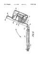
- FIG. 2is a partial cross-sectional view of the infusion device of FIG. 1 with the shells not engaged.
- FIG. 3is a side cross-sectional view of the top shell of FIG. 2.
- FIG. 4is a cross-sectional view of the infusion device of FIG. 1 with the shells fully engaged.
- FIGS. 5a and 5bare a plan view and side view, respectively, of the rotatable spring retainer used in the infusion device of FIG. 1.
- FIGS. 6a and 6bare a plan view and side view, respectively, of the platen used in the infusion device of FIG. 1.
- FIG. 7is a plan view of the fluid delivery bag of the present invention.
- FIG. 8is an isometric view of an alternate embodiment of the infusion device of the present invention.
- FIG. 9is a cross-sectional view of the infusion device of FIG. 8 in an open position.
- FIG. 10is a cross-sectional view of the infusion device of FIG. 8 in a closed position.
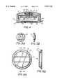
- FIG. 11is a plan view of a platen having a legend reading "EMPTY”.
- FIG. 12is a plan view of the platen pump of FIG. 2 illustrating the legend of FIG. 11 as seen through the transparent window when a fluid delivery bag contained within the pump is empty.
- the infusion device of the present inventionshall be called a platen pump.
- the platen pumpis formed in two parts, a pressurizing portion and a fluid containing portion. Each portion is housed in a container or shell.
- a pressurizing shell 12includes a helical spring 14.
- a fluid containing shell 16includes a chamber 17 for housing a fluid delivery bag 18.
- the pressurizing shell 12 and the fluid containing shell 16are connected to form the enclosed pump, the fluid delivery bag is pressurized by the spring 14. Fluid is thus continuously forced out of the bag 18 through an outlet tube 20 in fluid communication therewith. Controlled fluid flow is achieved with a small diameter fixed orifice 46 located at the end of the tube.
- the pump of FIG. 1is 31/2" in diameter and 1.7" high.
- a selectively releasable clamp 34may be applied to the outlet tube to stop fluid flow from the pump. Releasing the clamp restores fluid flow.
- the pressurizing meansis a conical helical coil spring 14.
- the springis formed from stainless steel or a suitable spring material.
- the coils of the springare made progressively larger so that when compressed the spring coils can overlap to compress to a lower height than a conventional compression spring.
- the working lengthis but a fraction of its total free length. This insures that the force applied by the spring is kept within an acceptable tolerance from the beginning to the end of the infusion.
- the change in force exerted by the spring over the course of an infusion as compared to the initial force it exerts when compressed against a full fluid delivery bagis less than 20%.
- the spring lengthshould be selected such that the change in force over the course of an infusion is less than 30%. In addition to a conventional compression spring, this concept would apply to a leaf spring, if it was used instead, where the deflection in the leaf spring is but a fraction of the total possible deflection.
- a flexible cable retainer 26encircles the spring 14 to set its initial compressed height and also to prevent it from expanding beyond the height of the pressurizing shell 12.
- two cables 26are used.
- the spring 14does not bear against the fluid delivery bag when the pressurizing shell 12 is initially engaged with the fluid containing shell 16. This makes it easy for a user to bring the two shells together.
- the force differential between the full position shown in FIG. 4 and empty position with the bag squeezed to a completely collapsed positionis less than 30% of the initial force in the full position.
- the conical helical coil springis preferred, it would be possible to make a platen pump with a leaf spring, a pressurized bladder, a standard helical compression spring or a canister of pressurized gas to act as the pressurizing means.
- the smallest coil of the springis rotatably attached to the closed end of the pressurizing shell 12.
- the springis attached to the pressurizing shell by a rotatable connector including a spring retainer 22, an anchor pivot 28, a spring stop 23 and a screw 31.
- the anchor pivot 28is seated on a shoulder 29 encircling a hole in the top of the pressurizing shell 12.
- the anchor pivot 28is free to rotate on the shoulder 29.
- the rotatable spring retainer 22is mounted to an anchor pivot 28.
- the spring retainer 22centers the spring to the shell.
- a spring stop 23clamps the end coil of the spring to the spring retainer and prevents the spring from dislodging from the spring retainer 22.
- the screw 31holds the anchor pivot 28 and the spring stop 23 together.
- the spring retainer 22is sandwiched between the anchor pivot and the spring stop.
- a fluid delivery bagis pressurized to only about 5 psi which requires only about 30 pounds of force.
- the pressurizing shell 12 and fluid containing shell 16are threadably engaged.
- the pressurizing shellhas inner helical threads 13 and the fluid containing shell has outer helical threads 19.
- the threadsprovide a mechanical advantage so that a modest amount of torque can generate sufficient amounts of axial load to compress the spring.
- a platen 24is located between the spring 14 and the fluid delivery bag 18 when the two shells are connected.
- the platen 24distributes the pressure from the spring 14 over the bag.
- the presently preferred platenis made of polycarbonate.
- the platenhas a bottom flat portion which extends over an area no greater than a substantially flat central portion of the fluid delivery bag. This serves to keep the contacting surface areas fairly constant over the course of the entire infusion to help minimize changes in pressure on the fluid bag.
- the platen 24is held against the helical coil within the pressurizing shell 12 by the flexible restraining cable 26.
- the cable 26is preferably made from multi-strand stainless steel. It is looped about the rotatable retainer 22 and the platen 24. Preferably, two cable loops 26 are used. Grooves are provided in the retainer 22 and platen 24 to accommodate the cables 26.
- a plastic label 36may be adhered to the bottom of the platen 24 thereby holding the cables 26 within their grooves.
- the spring 14, platen 24 and rotatable connectorare secured to one another by the cables 26.
- the anchor pivot 28, the spring 14, spring retainer 22, spring stop 23, the platen 24 and the cable 26all rotate freely about the axis of the pressurizing shell.
- the platen 24should remain stationary with respect to the fluid delivery bag so that no torsional load is imparted on the bag.
- anti-rotation tabscan be attached to the outer edge of the platen 24. The tabs would extend out radially to engage slots in the wall of the fluid containing shell 16.
- the tabswould be guided in the slot, thus preventing the platen from turning with respect to the fluid containing shell. It has been found that rotatably attaching the spring and platen to the pressurizing shell is sufficient to avoid applying undesirable torque to the fluid delivery bag.
- the tabs and slotsare not required.
- preferred embodiments of the present inventionutilize a clear plastic window 38 in the bottom of the fluid containing shell 16. Due to cost and safety considerations, especially preferred embodiments of the present invention use a clear plastic, such as polycarbonate, as the window material.
- a legend 45such as the word "Empty” is printed on the bottom side of the platen 24, as shown in FIG. 11, or on the label 36.
- the legendwill be fuzzy or illegible when viewed through the transparent window when there is liquid in the fluid delivery bag.
- the legend on the platen 24comes into focus through the bottom of the fluid containing shell due to the translucent nature of the fluid delivery bag, as shown in FIG. 12. This can be used to provide a clear indication of when the fluid bag is empty.
- the surface area of contact between the bag and the rigid surfaces pressing against itshould be kept constant.
- the bottom of the chamber 17 in the fluid containing shell 16is contoured to evenly support the bottom of the bag over its entire area.
- the surface contact against the bottom of the bagremains constant during the full stroke of the platen.
- a curved contouris shown about the periphery of the chamber 17.
- the bag 18 when filled with fluidmatches this curved contour to receive support over its entire area.
- the contour of the chamber 17could also be achieved with a 45° angle about the periphery. While the bag 18 might not completely fill the corner formed by the angle, the contour of the surface areas should be adequate to provide substantial support and contact with the bag's entire area.
- the platen 24has a bottom flat surface which does not extend beyond a flat central portion of the fluid delivery bag. If only the flat portion of the platen were to act on the bag, a residual fluid would remain in the bag about its periphery at the end of the infusion.
- the platenhas a chamfered edge 40 and a recessed outer ring 42. These portions of the platen roughly match the contour of the periphery of the bottom of the chamber 17. A platen 24 with a periphery that conforms more exactly to the contour of the chamber bottom could also be used. Near the end of an infusion, as the platen 24 descends towards the chamber bottom, fluid which builds up about the periphery of the bag 18 is pushed out by the edge 40 and the recessed ring 42.
- An opening 30is provided in the fluid-containing shell through which the outlet tube connected to the fluid delivery bag 18 can be extended.
- An outer wall 32 of the fluid containing shellcan be provided to serve as a grip. When screwing the shells together, one hand holds the outer wall of the pressurizing shell and the other hand holds the outer wall 32 of the fluid containing shell 16.
- the fluid delivery bag 18 for use in the platen pumpis a circular pouch connected to an outlet tube.
- the circular pouchadvantageously, has no corners.
- the seam 44 of the bagis uniformly stressed.
- the periphery of the baghas a curved contour when filled.
- the center portion of the bagis substantially flat so that the contacting surfaces between the platen and the bag can remain relatively constant throughout an infusion.
- the bagis made from a suitable pliable biocompatible plastic material, such as a class VI, PVC biocompatible plastic.
- the bagis formed from two circular sheets that are RF welded together around their circumference. The round shape of the bag achieves uniform stress on the welded seam.
- the outlet tube 20is connected to the bag 18.
- the tube 20may lead to a restricted orifice 46 which restrains the flow of fluid from the delivery bag when it is pressurized.
- Orificesof 0.004 to 0.008" diameter are presently contemplated.
- a particulate filter 48be inserted in the outlet tube to stop the flow of particles which might occlude the orifice.
- the orificeprovides a relatively constant fluid flow.
- a length of tubing of known diametere.g., an 18 in. length of 0.015" tube can be substituted.
- a Y-injection site 52may be inserted into the outlet tube 20.
- the Y-injection site 52includes a latex rubber self-sealing septum 54 through which a needle may be inserted to inject fluid into the bag.
- the end of the outlet tubecan be connected to a luer adapter 50.
- the adapteris a threadably engaged connector. It is designed to mate with a threadably engaged disconnect on an IV line.
- the outlet tube 20 of the fluid delivery bagcan be directly connected to a second luer adapter 50 (not illustrated) approximately 3 inches from the drug bag.
- a clampwould be used on the tube between the bag and the luer adapter 50. Fluid may be injected in through the luer adapter 50 so a Y-injection site would not be needed.
- a new drug bagmay be attached to the IV set, thus reusing the IV set for multiple doses over a 24 to 48 hour period.
- the clamp 34is used to close the outlet tube on an empty drug delivery bag.
- a needlepierces the septum 54 to inject fluid into the drug delivery bag.
- the bag when fullshould have a substantially flat top and bottom central portion when resting on a flat surface.
- the needleis removed.
- the bag, with its permanently affixed IV lineis placed in the chamber 17 of fluid containing shell 16 with the IV line passing through the opening 30 in the bottom of the shell.
- the threadsshould preferably engage initially before the platen 24 pressurizes the bag.
- the two shellsare then simply screwed together until a stop position is reached. At this point, the drug bag is fully pressurized.
- the IV output lineis purged of air by opening the clamp 34 and allowing fluid to flow. Once the fluid stream ejects slightly, the tube can be reclamped. The output line is then connected to a catheter line or needle for administering an infusion to a patient. Releasing the clamp initiates fluid flow. When the legend on the platen 24 comes into focus through the window 38 in the fluid containing shell 16, the bag has been emptied. The output line is removed or disconnected from the patient. The two shells are then unscrewed and the drug container and IV line are discarded. The pump can be reused.
- the numerical labels in the drawingsare 100 higher than corresponding elements in the first embodiment.
- the fluid containing shell 116 of the alternate embodimentis provided with a rectangular chamber to accommodate the rectangular drug delivery bag.
- the fluid containing shell 116is formed by an upper portion 152 and lower portion 154 attached at one end by a hinge 156. The opposite ends are connected by a latch 158 when the upper and lower portions are closed.
- the upper portion 152includes a threaded cylindrical wall 119 for interfacing with the threaded wall 113 of the pressurizing shell 112.
- the platen 124 attached to the spring 114 of the pressurizing shell 112is made rectangular to fit over the substantially flat center portion of the rectangular bag.
- the pressurizing shellis unscrewed and loosened on the fluid containing shell.
- the fluid containing shellis opened about its hinge.
- a fluid delivery bagis inserted.
- the fluid containing shellis closed at its latch.
- the pressurizing shellcan then be screwed onto the fluid containing shell to pressurize the drug delivery bag.
Landscapes
- Health & Medical Sciences (AREA)
- Vascular Medicine (AREA)
- Engineering & Computer Science (AREA)
- Anesthesiology (AREA)
- Biomedical Technology (AREA)
- Heart & Thoracic Surgery (AREA)
- Hematology (AREA)
- Life Sciences & Earth Sciences (AREA)
- Animal Behavior & Ethology (AREA)
- General Health & Medical Sciences (AREA)
- Public Health (AREA)
- Veterinary Medicine (AREA)
- Infusion, Injection, And Reservoir Apparatuses (AREA)
- Medical Preparation Storing Or Oral Administration Devices (AREA)
Abstract
Description
Claims (4)
Priority Applications (20)
| Application Number | Priority Date | Filing Date | Title |
|---|---|---|---|
| US07/824,855US5911716A (en) | 1992-01-24 | 1992-01-24 | Platen pump |
| JP4226472AJPH05220204A (en) | 1992-01-24 | 1992-08-03 | Injection device, fluid administration bag and injection method |
| PCT/US1993/000565WO1993014797A2 (en) | 1992-01-24 | 1993-01-22 | Platen pump |
| JP5513332AJPH07503162A (en) | 1992-01-24 | 1993-01-22 | platen pump |
| SG1996001952ASG48811A1 (en) | 1992-01-24 | 1993-01-22 | Platen pump |
| EP93903630AEP0624102B1 (en) | 1992-01-24 | 1993-01-22 | Platen pump |
| DE69332877TDE69332877T9 (en) | 1992-01-24 | 1993-01-22 | Pump with pressure plate |
| AU34819/93AAU3481993A (en) | 1992-01-24 | 1993-01-22 | Platen pump |
| ES93903630TES2191661T3 (en) | 1992-01-24 | 1993-01-22 | PLATINUM PUMP. |
| DK93903630TDK0624102T3 (en) | 1992-01-24 | 1993-01-22 | Pressure plate Pump |
| CA002126320ACA2126320C (en) | 1992-01-24 | 1993-01-22 | Platen pump |
| AT93903630TATE237378T1 (en) | 1992-01-24 | 1993-01-22 | PUMP WITH PRESSURE PLATE |
| PT93903630TPT624102E (en) | 1992-01-24 | 1993-01-22 | PUMP PUMP |
| AU12679/97AAU1267997A (en) | 1992-01-24 | 1997-02-14 | Platen pump |
| US08/876,180US6251098B1 (en) | 1992-01-24 | 1997-06-23 | Fluid container for use with platen pump |
| US08/987,601US6358239B1 (en) | 1992-01-24 | 1997-12-09 | Platen pump |
| US09/892,900US7337922B2 (en) | 1992-01-24 | 2001-06-26 | Platen pump |
| US10/078,063US6626329B2 (en) | 1992-01-24 | 2002-02-18 | Platen pump |
| US10/678,038US6871759B2 (en) | 1992-01-24 | 2003-09-30 | Platen pump |
| US11/088,672US7083068B2 (en) | 1992-01-24 | 2005-03-24 | Platen pump |
Applications Claiming Priority (1)
| Application Number | Priority Date | Filing Date | Title |
|---|---|---|---|
| US07/824,855US5911716A (en) | 1992-01-24 | 1992-01-24 | Platen pump |
Related Child Applications (2)
| Application Number | Title | Priority Date | Filing Date |
|---|---|---|---|
| US89895892AContinuation-In-Part | 1992-01-24 | 1992-06-15 | |
| US29001364Continuation-In-Part | 1992-11-12 |
Publications (1)
| Publication Number | Publication Date |
|---|---|
| US5911716Atrue US5911716A (en) | 1999-06-15 |
Family
ID=25242489
Family Applications (1)
| Application Number | Title | Priority Date | Filing Date |
|---|---|---|---|
| US07/824,855Expired - LifetimeUS5911716A (en) | 1992-01-24 | 1992-01-24 | Platen pump |
Country Status (2)
| Country | Link |
|---|---|
| US (1) | US5911716A (en) |
| JP (1) | JPH05220204A (en) |
Cited By (77)
| Publication number | Priority date | Publication date | Assignee | Title |
|---|---|---|---|---|
| US6358239B1 (en)* | 1992-01-24 | 2002-03-19 | I-Flow Corporation | Platen pump |
| WO2002041937A1 (en)* | 2000-11-22 | 2002-05-30 | Roland Wex | Mechanically actuated liquid pump |
| US6485461B1 (en) | 2000-04-04 | 2002-11-26 | Insulet, Inc. | Disposable infusion device |
| US20030187394A1 (en)* | 2002-04-02 | 2003-10-02 | Wilkinson Bradley M | Method and device for intradermally delivering a substance |
| US6656158B2 (en) | 2002-04-23 | 2003-12-02 | Insulet Corporation | Dispenser for patient infusion device |
| US6656159B2 (en) | 2002-04-23 | 2003-12-02 | Insulet Corporation | Dispenser for patient infusion device |
| US6669669B2 (en) | 2001-10-12 | 2003-12-30 | Insulet Corporation | Laminated patient infusion device |
| US20040015131A1 (en)* | 2002-07-16 | 2004-01-22 | Flaherty J. Christopher | Flow restriction system and method for patient infusion device |
| US20040027083A1 (en)* | 2002-04-26 | 2004-02-12 | Toyoda Koki Kabushiki Kaisha | Motor control device |
| US6692457B2 (en) | 2002-03-01 | 2004-02-17 | Insulet Corporation | Flow condition sensor assembly for patient infusion device |
| US6699218B2 (en) | 2000-11-09 | 2004-03-02 | Insulet Corporation | Transcutaneous delivery means |
| US20040064088A1 (en)* | 2002-09-30 | 2004-04-01 | William Gorman | Dispenser components and methods for patient infusion device |
| US20040064096A1 (en)* | 2002-09-30 | 2004-04-01 | Flaherty J. Christopher | Components and methods for patient infusion device |
| US6723072B2 (en) | 2002-06-06 | 2004-04-20 | Insulet Corporation | Plunger assembly for patient infusion device |
| US20040087894A1 (en)* | 2000-09-08 | 2004-05-06 | Flaherty J. Christopher | Devices, systems and methods for patient infusion |
| US20040092865A1 (en)* | 2001-11-09 | 2004-05-13 | J. Christopher Flaherty | Transcutaneous delivery means |
| US6749587B2 (en) | 2001-02-22 | 2004-06-15 | Insulet Corporation | Modular infusion device and method |
| US20040116866A1 (en)* | 2002-12-17 | 2004-06-17 | William Gorman | Skin attachment apparatus and method for patient infusion device |
| US6768425B2 (en) | 2000-12-21 | 2004-07-27 | Insulet Corporation | Medical apparatus remote control and method |
| US20040153032A1 (en)* | 2002-04-23 | 2004-08-05 | Garribotto John T. | Dispenser for patient infusion device |
| US6830558B2 (en) | 2002-03-01 | 2004-12-14 | Insulet Corporation | Flow condition sensor assembly for patient infusion device |
| US20050027242A1 (en)* | 2002-04-02 | 2005-02-03 | Becton, Dickinson And Company | Intradermal delivery device |
| US20050065760A1 (en)* | 2003-09-23 | 2005-03-24 | Robert Murtfeldt | Method for advising patients concerning doses of insulin |
| US20050070847A1 (en)* | 2003-09-29 | 2005-03-31 | Van Erp Wilhelmus Petrus Martinus Maria | Rapid-exchange balloon catheter with hypotube shaft |
| US20050177136A1 (en)* | 2003-12-19 | 2005-08-11 | Miller Landon C. | Externally disposed pump for use with an internally mounted and compliant catheter |
| US6960192B1 (en) | 2002-04-23 | 2005-11-01 | Insulet Corporation | Transcutaneous fluid delivery system |
| WO2005115503A1 (en)* | 2004-05-31 | 2005-12-08 | Maosheng Lai | An automatic pressurized box for infusing liquid or blood which can be used in disaster area saving and indoor or outdoor emergency treatment |
| US20060106367A1 (en)* | 2001-06-01 | 2006-05-18 | Massengale Roger D | Large volume bolus device and method |
| US7337922B2 (en)* | 1992-01-24 | 2008-03-04 | I-Flow Corporation | Platen pump |
| US20080195047A1 (en)* | 2007-02-09 | 2008-08-14 | Mitchell Price | Enteral feeding systems, devices and methods |
| US20080215029A1 (en)* | 1993-01-22 | 2008-09-04 | I-Flow Corporation | Platen pump |
| US20100063486A1 (en)* | 2006-09-25 | 2010-03-11 | Koninklijke Philips Electronics N.V. | Medicament delivery apparatus |
| US20100102085A1 (en)* | 2008-10-23 | 2010-04-29 | Kanfer Joseph S | Handheld dispensers for personal use |
| US20120136304A1 (en)* | 2008-12-03 | 2012-05-31 | Roche Diagnostics International Ag | Flexible container with a preformed fluid channel and infusion pump device using such a container |
| CN105307710A (en)* | 2013-06-14 | 2016-02-03 | 诺和诺德股份有限公司 | Drug delivery device with double layer spring |
| US9327507B2 (en)* | 2013-02-20 | 2016-05-03 | Océ-Technologies B.V. | Liquid container |
| US10342926B2 (en) | 2016-05-26 | 2019-07-09 | Insulet Corporation | Single dose drug delivery device |
| JP2019520931A (en)* | 2016-07-14 | 2019-07-25 | サノフイSanofi | Drug delivery system |
| US10363372B2 (en) | 2016-08-12 | 2019-07-30 | Insulet Corporation | Plunger for drug delivery device |
| US10441723B2 (en) | 2016-08-14 | 2019-10-15 | Insulet Corporation | Variable fill drug delivery device |
| US10603440B2 (en) | 2017-01-19 | 2020-03-31 | Insulet Corporation | Cartridge hold-up volume reduction |
| US10695485B2 (en) | 2017-03-07 | 2020-06-30 | Insulet Corporation | Very high volume user filled drug delivery device |
| US10751478B2 (en) | 2016-10-07 | 2020-08-25 | Insulet Corporation | Multi-stage delivery system |
| US10780217B2 (en) | 2016-11-10 | 2020-09-22 | Insulet Corporation | Ratchet drive for on body delivery system |
| US10874803B2 (en) | 2018-05-31 | 2020-12-29 | Insulet Corporation | Drug cartridge with drive system |
| US10898656B2 (en) | 2017-09-26 | 2021-01-26 | Insulet Corporation | Needle mechanism module for drug delivery device |
| CN112384268A (en)* | 2018-07-11 | 2021-02-19 | 生物技术公司 | Drug delivery system |
| US10973978B2 (en) | 2017-08-03 | 2021-04-13 | Insulet Corporation | Fluid flow regulation arrangements for drug delivery devices |
| US11045603B2 (en) | 2017-02-22 | 2021-06-29 | Insulet Corporation | Needle insertion mechanisms for drug containers |
| US11090434B2 (en) | 2015-11-24 | 2021-08-17 | Insulet Corporation | Automated drug delivery system |
| WO2021155048A3 (en)* | 2020-01-30 | 2021-10-14 | Cercacor Laboratories, Inc. | Redundant staggered glucose sensor disease management system |
| US11147931B2 (en) | 2017-11-17 | 2021-10-19 | Insulet Corporation | Drug delivery device with air and backflow elimination |
| US11229736B2 (en) | 2018-06-06 | 2022-01-25 | Insulet Corporation | Linear shuttle pump for drug delivery |
| US11229741B2 (en) | 2012-03-30 | 2022-01-25 | Insulet Corporation | Fluid delivery device, transcutaneous access tool and fluid drive mechanism for use therewith |
| US11280327B2 (en) | 2017-08-03 | 2022-03-22 | Insulet Corporation | Micro piston pump |
| US11364341B2 (en) | 2015-11-25 | 2022-06-21 | Insulet Corporation | Wearable medication delivery device |
| US11369735B2 (en) | 2019-11-05 | 2022-06-28 | Insulet Corporation | Component positioning of a linear shuttle pump |
| US11446435B2 (en) | 2018-11-28 | 2022-09-20 | Insulet Corporation | Drug delivery shuttle pump system and valve assembly |
| US11786668B2 (en) | 2017-09-25 | 2023-10-17 | Insulet Corporation | Drug delivery devices, systems, and methods with force transfer elements |
| US11857763B2 (en) | 2016-01-14 | 2024-01-02 | Insulet Corporation | Adjusting insulin delivery rates |
| US11865299B2 (en) | 2008-08-20 | 2024-01-09 | Insulet Corporation | Infusion pump systems and methods |
| US11929158B2 (en) | 2016-01-13 | 2024-03-12 | Insulet Corporation | User interface for diabetes management system |
| USD1020794S1 (en) | 2018-04-02 | 2024-04-02 | Bigfoot Biomedical, Inc. | Medication delivery device with icons |
| USD1024090S1 (en) | 2019-01-09 | 2024-04-23 | Bigfoot Biomedical, Inc. | Display screen or portion thereof with graphical user interface associated with insulin delivery |
| US11969579B2 (en) | 2017-01-13 | 2024-04-30 | Insulet Corporation | Insulin delivery methods, systems and devices |
| US12042630B2 (en) | 2017-01-13 | 2024-07-23 | Insulet Corporation | System and method for adjusting insulin delivery |
| US12064591B2 (en) | 2013-07-19 | 2024-08-20 | Insulet Corporation | Infusion pump system and method |
| US12076160B2 (en) | 2016-12-12 | 2024-09-03 | Insulet Corporation | Alarms and alerts for medication delivery devices and systems |
| US12097355B2 (en) | 2023-01-06 | 2024-09-24 | Insulet Corporation | Automatically or manually initiated meal bolus delivery with subsequent automatic safety constraint relaxation |
| US12106837B2 (en) | 2016-01-14 | 2024-10-01 | Insulet Corporation | Occlusion resolution in medication delivery devices, systems, and methods |
| US12318577B2 (en) | 2017-01-13 | 2025-06-03 | Insulet Corporation | System and method for adjusting insulin delivery |
| US12343502B2 (en) | 2017-01-13 | 2025-07-01 | Insulet Corporation | System and method for adjusting insulin delivery |
| US12359903B2 (en) | 2021-05-28 | 2025-07-15 | Insulet Corporation | Spring-based status sensors |
| US12377208B2 (en) | 2021-01-08 | 2025-08-05 | Insulet Corporation | Single actuated precision dose intermediate pumping chamber |
| US12383166B2 (en) | 2016-05-23 | 2025-08-12 | Insulet Corporation | Insulin delivery system and methods with risk-based set points |
| US12433512B2 (en) | 2020-12-18 | 2025-10-07 | Insulet Corporation | Adhesive pad with a metallic coil for securing an on-body medical device |
| US12440617B2 (en) | 2022-01-05 | 2025-10-14 | Insulet Corporation | Linear activated drug dosing pump system |
Families Citing this family (2)
| Publication number | Priority date | Publication date | Assignee | Title |
|---|---|---|---|---|
| DE19652796A1 (en)* | 1996-12-18 | 1998-06-25 | Siemens Ag | Variable speed AC motor stator design |
| DE29701861U1 (en)* | 1997-02-04 | 1998-06-10 | Fresenius Ag, 61350 Bad Homburg | Device for dosing medical liquids |
Citations (45)
| Publication number | Priority date | Publication date | Assignee | Title |
|---|---|---|---|---|
| US3029983A (en)* | 1960-04-08 | 1962-04-17 | Rupert S Wagenhals | Dispenser for simultaneously discharging material from a plurality of collapsible tubes |
| US3048171A (en)* | 1958-11-03 | 1962-08-07 | Bio Physical Res Inc | Intravenous injection device |
| US3151616A (en)* | 1962-07-25 | 1964-10-06 | Paul M Selfon | Automatic transfusion apparatus |
| US3384080A (en)* | 1964-10-16 | 1968-05-21 | Us Catheter & Instr Corp | Portable spring powered infusion device having escapement means controlling speed ofinfusion |
| US3451393A (en)* | 1966-02-07 | 1969-06-24 | Stanley J Sarnoff | Automatic infusion device |
| US3468308A (en)* | 1966-01-17 | 1969-09-23 | Howard R Bierman | Pressure infusion device for ambulatory patients with pressure control means |
| US3469578A (en)* | 1965-10-12 | 1969-09-30 | Howard R Bierman | Infusion device for ambulatory patients with flow control means |
| US3565292A (en)* | 1969-03-03 | 1971-02-23 | Walter J Jinotti | Blood-profusing apparatus |
| US3595232A (en)* | 1968-08-19 | 1971-07-27 | Saul Leibinsohn | Nongravitational infusion assembly |
| US3625401A (en)* | 1969-11-20 | 1971-12-07 | John Vaden Terry | Pump for blood plasma and the like |
| US3640276A (en)* | 1970-01-09 | 1972-02-08 | Allis Chalmers Mfg Co | Apparatus for making intravenous or intra-arterial injections |
| US3640277A (en)* | 1968-12-09 | 1972-02-08 | Marvin Adelberg | Medical liquid administration device |
| US3647117A (en)* | 1969-08-22 | 1972-03-07 | Thomas S Hargest | Apparatus for intravenous feeding and the like |
| US3670926A (en)* | 1969-09-11 | 1972-06-20 | Power Technology Corp | Intravenous feeding apparatus |
| US3731681A (en)* | 1970-05-18 | 1973-05-08 | Univ Minnesota | Implantable indusion pump |
| US3734351A (en)* | 1970-08-03 | 1973-05-22 | Labaz | Press for a deformable bag |
| US3847304A (en)* | 1973-08-13 | 1974-11-12 | M Cohen | Bag-type fluid and paste dispenser |
| US3895741A (en)* | 1971-09-28 | 1975-07-22 | Bestnu Engineering Pty | Intravenous fluids administration apparatus |
| US3895631A (en)* | 1974-02-04 | 1975-07-22 | Alza Corp | Liquid infusion unit |
| US4033479A (en)* | 1976-07-26 | 1977-07-05 | Nasa | Pressure modulating valve |
| US4059110A (en)* | 1976-10-07 | 1977-11-22 | Timex Corporation | Clockwork driven hypodermic syringe |
| US4077544A (en)* | 1976-08-16 | 1978-03-07 | Donald Gutkowski | Fluid transfer device |
| US4140117A (en)* | 1975-05-12 | 1979-02-20 | Alza Corporation | Cartridge for liquid infusion apparatus |
| US4157771A (en)* | 1977-10-07 | 1979-06-12 | The Gorman-Rupp Company | Bag compressing device for dispensing fluid |
| US4265241A (en)* | 1979-02-28 | 1981-05-05 | Andros Incorporated | Implantable infusion device |
| US4274407A (en)* | 1979-11-13 | 1981-06-23 | Med Pump, Inc. | Fluid injection system |
| US4313439A (en)* | 1980-03-24 | 1982-02-02 | Biotek, Inc. | Automated, spring-powered medicament infusion system |
| US4337769A (en)* | 1980-08-01 | 1982-07-06 | Baxter Travenol Laboratories, Inc. | Pressure infusion module |
| DE3507818C1 (en)* | 1985-03-06 | 1986-07-24 | B. Braun Melsungen Ag, 3508 Melsungen | Infusion pump |
| US4650469A (en)* | 1984-10-19 | 1987-03-17 | Deltec Systems, Inc. | Drug delivery system |
| US4741736A (en)* | 1986-12-10 | 1988-05-03 | I-Flow Corporation | Programmable infusion pump |
| GB2197691A (en)* | 1986-11-23 | 1988-05-25 | Dan Bron | Hydraulic pump |
| US4756450A (en)* | 1984-07-04 | 1988-07-12 | Battelle Memorial Institute | Dispenser of drinks capable of releasing gas in solution |
| US4769008A (en)* | 1986-11-26 | 1988-09-06 | Infusion Systems Corporation | Pressurized fluid dispenser |
| US4772263A (en)* | 1986-02-03 | 1988-09-20 | Regents Of The University Of Minnesota | Spring driven infusion pump |
| US4781689A (en)* | 1986-11-13 | 1988-11-01 | Andrew Sealfon | Spring-operated liquid-dispensing device |
| US4915693A (en)* | 1986-11-26 | 1990-04-10 | Baxter International, Inc. | Pressurized fluid dispenser |
| US4950245A (en)* | 1988-07-08 | 1990-08-21 | I-Flow Corporation | Multiple fluid cartridge and pump |
| US4966585A (en)* | 1988-05-31 | 1990-10-30 | Gangemi Ronald J | Infusion apparatus |
| US4968301A (en)* | 1989-02-02 | 1990-11-06 | Imed Corporation | Disposable infusion device |
| US4991742A (en)* | 1989-08-01 | 1991-02-12 | Chang Chin Fu | Automatic drip bottle set |
| EP0426319A2 (en)* | 1989-10-31 | 1991-05-08 | Block Medical, Inc. | Infusion apparatus |
| US5053031A (en)* | 1988-03-29 | 1991-10-01 | Baxter International Inc. | Pump infusion system |
| US5176641A (en)* | 1991-07-08 | 1993-01-05 | Infusaid, Inc. | Implantable drug infusion reservoir having fluid impelling resilient foam member |
| US5178609A (en)* | 1990-06-19 | 1993-01-12 | Kato Hatsujo Kaisha, Ltd. | Medical liquid injector for continuous transfusion |
- 1992
- 1992-01-24USUS07/824,855patent/US5911716A/ennot_activeExpired - Lifetime
- 1992-08-03JPJP4226472Apatent/JPH05220204A/enactivePending
Patent Citations (45)
| Publication number | Priority date | Publication date | Assignee | Title |
|---|---|---|---|---|
| US3048171A (en)* | 1958-11-03 | 1962-08-07 | Bio Physical Res Inc | Intravenous injection device |
| US3029983A (en)* | 1960-04-08 | 1962-04-17 | Rupert S Wagenhals | Dispenser for simultaneously discharging material from a plurality of collapsible tubes |
| US3151616A (en)* | 1962-07-25 | 1964-10-06 | Paul M Selfon | Automatic transfusion apparatus |
| US3384080A (en)* | 1964-10-16 | 1968-05-21 | Us Catheter & Instr Corp | Portable spring powered infusion device having escapement means controlling speed ofinfusion |
| US3469578A (en)* | 1965-10-12 | 1969-09-30 | Howard R Bierman | Infusion device for ambulatory patients with flow control means |
| US3468308A (en)* | 1966-01-17 | 1969-09-23 | Howard R Bierman | Pressure infusion device for ambulatory patients with pressure control means |
| US3451393A (en)* | 1966-02-07 | 1969-06-24 | Stanley J Sarnoff | Automatic infusion device |
| US3595232A (en)* | 1968-08-19 | 1971-07-27 | Saul Leibinsohn | Nongravitational infusion assembly |
| US3640277A (en)* | 1968-12-09 | 1972-02-08 | Marvin Adelberg | Medical liquid administration device |
| US3565292A (en)* | 1969-03-03 | 1971-02-23 | Walter J Jinotti | Blood-profusing apparatus |
| US3647117A (en)* | 1969-08-22 | 1972-03-07 | Thomas S Hargest | Apparatus for intravenous feeding and the like |
| US3670926A (en)* | 1969-09-11 | 1972-06-20 | Power Technology Corp | Intravenous feeding apparatus |
| US3625401A (en)* | 1969-11-20 | 1971-12-07 | John Vaden Terry | Pump for blood plasma and the like |
| US3640276A (en)* | 1970-01-09 | 1972-02-08 | Allis Chalmers Mfg Co | Apparatus for making intravenous or intra-arterial injections |
| US3731681A (en)* | 1970-05-18 | 1973-05-08 | Univ Minnesota | Implantable indusion pump |
| US3734351A (en)* | 1970-08-03 | 1973-05-22 | Labaz | Press for a deformable bag |
| US3895741A (en)* | 1971-09-28 | 1975-07-22 | Bestnu Engineering Pty | Intravenous fluids administration apparatus |
| US3847304A (en)* | 1973-08-13 | 1974-11-12 | M Cohen | Bag-type fluid and paste dispenser |
| US3895631A (en)* | 1974-02-04 | 1975-07-22 | Alza Corp | Liquid infusion unit |
| US4140117A (en)* | 1975-05-12 | 1979-02-20 | Alza Corporation | Cartridge for liquid infusion apparatus |
| US4033479A (en)* | 1976-07-26 | 1977-07-05 | Nasa | Pressure modulating valve |
| US4077544A (en)* | 1976-08-16 | 1978-03-07 | Donald Gutkowski | Fluid transfer device |
| US4059110A (en)* | 1976-10-07 | 1977-11-22 | Timex Corporation | Clockwork driven hypodermic syringe |
| US4157771A (en)* | 1977-10-07 | 1979-06-12 | The Gorman-Rupp Company | Bag compressing device for dispensing fluid |
| US4265241A (en)* | 1979-02-28 | 1981-05-05 | Andros Incorporated | Implantable infusion device |
| US4274407A (en)* | 1979-11-13 | 1981-06-23 | Med Pump, Inc. | Fluid injection system |
| US4313439A (en)* | 1980-03-24 | 1982-02-02 | Biotek, Inc. | Automated, spring-powered medicament infusion system |
| US4337769A (en)* | 1980-08-01 | 1982-07-06 | Baxter Travenol Laboratories, Inc. | Pressure infusion module |
| US4756450A (en)* | 1984-07-04 | 1988-07-12 | Battelle Memorial Institute | Dispenser of drinks capable of releasing gas in solution |
| US4650469A (en)* | 1984-10-19 | 1987-03-17 | Deltec Systems, Inc. | Drug delivery system |
| DE3507818C1 (en)* | 1985-03-06 | 1986-07-24 | B. Braun Melsungen Ag, 3508 Melsungen | Infusion pump |
| US4772263A (en)* | 1986-02-03 | 1988-09-20 | Regents Of The University Of Minnesota | Spring driven infusion pump |
| US4781689A (en)* | 1986-11-13 | 1988-11-01 | Andrew Sealfon | Spring-operated liquid-dispensing device |
| GB2197691A (en)* | 1986-11-23 | 1988-05-25 | Dan Bron | Hydraulic pump |
| US4769008A (en)* | 1986-11-26 | 1988-09-06 | Infusion Systems Corporation | Pressurized fluid dispenser |
| US4915693A (en)* | 1986-11-26 | 1990-04-10 | Baxter International, Inc. | Pressurized fluid dispenser |
| US4741736A (en)* | 1986-12-10 | 1988-05-03 | I-Flow Corporation | Programmable infusion pump |
| US5053031A (en)* | 1988-03-29 | 1991-10-01 | Baxter International Inc. | Pump infusion system |
| US4966585A (en)* | 1988-05-31 | 1990-10-30 | Gangemi Ronald J | Infusion apparatus |
| US4950245A (en)* | 1988-07-08 | 1990-08-21 | I-Flow Corporation | Multiple fluid cartridge and pump |
| US4968301A (en)* | 1989-02-02 | 1990-11-06 | Imed Corporation | Disposable infusion device |
| US4991742A (en)* | 1989-08-01 | 1991-02-12 | Chang Chin Fu | Automatic drip bottle set |
| EP0426319A2 (en)* | 1989-10-31 | 1991-05-08 | Block Medical, Inc. | Infusion apparatus |
| US5178609A (en)* | 1990-06-19 | 1993-01-12 | Kato Hatsujo Kaisha, Ltd. | Medical liquid injector for continuous transfusion |
| US5176641A (en)* | 1991-07-08 | 1993-01-05 | Infusaid, Inc. | Implantable drug infusion reservoir having fluid impelling resilient foam member |
Cited By (113)
| Publication number | Priority date | Publication date | Assignee | Title |
|---|---|---|---|---|
| US6871759B2 (en) | 1992-01-24 | 2005-03-29 | I-Flow Corporation | Platen pump |
| US6626329B2 (en)* | 1992-01-24 | 2003-09-30 | I-Flow Corporation | Platen pump |
| US20050211725A1 (en)* | 1992-01-24 | 2005-09-29 | Rake Kenneth W | Platen pump |
| US6358239B1 (en)* | 1992-01-24 | 2002-03-19 | I-Flow Corporation | Platen pump |
| US20040108333A1 (en)* | 1992-01-24 | 2004-06-10 | Rake Kenneth W. | Platen pump |
| US7083068B2 (en) | 1992-01-24 | 2006-08-01 | I-Flow Corporation | Platen pump |
| US7337922B2 (en)* | 1992-01-24 | 2008-03-04 | I-Flow Corporation | Platen pump |
| US20080215029A1 (en)* | 1993-01-22 | 2008-09-04 | I-Flow Corporation | Platen pump |
| US6485461B1 (en) | 2000-04-04 | 2002-11-26 | Insulet, Inc. | Disposable infusion device |
| US7029455B2 (en) | 2000-09-08 | 2006-04-18 | Insulet Corporation | Devices, systems and methods for patient infusion |
| US20040087894A1 (en)* | 2000-09-08 | 2004-05-06 | Flaherty J. Christopher | Devices, systems and methods for patient infusion |
| US7137964B2 (en) | 2000-09-08 | 2006-11-21 | Insulet Corporation | Devices, systems and methods for patient infusion |
| US6699218B2 (en) | 2000-11-09 | 2004-03-02 | Insulet Corporation | Transcutaneous delivery means |
| WO2002041937A1 (en)* | 2000-11-22 | 2002-05-30 | Roland Wex | Mechanically actuated liquid pump |
| US6768425B2 (en) | 2000-12-21 | 2004-07-27 | Insulet Corporation | Medical apparatus remote control and method |
| US6749587B2 (en) | 2001-02-22 | 2004-06-15 | Insulet Corporation | Modular infusion device and method |
| US20060106367A1 (en)* | 2001-06-01 | 2006-05-18 | Massengale Roger D | Large volume bolus device and method |
| US7815604B2 (en)* | 2001-06-01 | 2010-10-19 | I-Flow Corporation | Large volume bolus device and method |
| US6669669B2 (en) | 2001-10-12 | 2003-12-30 | Insulet Corporation | Laminated patient infusion device |
| US20050021005A1 (en)* | 2001-10-12 | 2005-01-27 | Flaherty J. Christopher | Laminated patient infusion device |
| US20040092865A1 (en)* | 2001-11-09 | 2004-05-13 | J. Christopher Flaherty | Transcutaneous delivery means |
| US6692457B2 (en) | 2002-03-01 | 2004-02-17 | Insulet Corporation | Flow condition sensor assembly for patient infusion device |
| US7887505B2 (en) | 2002-03-01 | 2011-02-15 | Insulet Corporation | Flow condition sensor assembly for patient infusion device |
| US6830558B2 (en) | 2002-03-01 | 2004-12-14 | Insulet Corporation | Flow condition sensor assembly for patient infusion device |
| US7156838B2 (en)* | 2002-04-02 | 2007-01-02 | Becton, Dickinson And Company | Intradermal delivery device |
| US20050027242A1 (en)* | 2002-04-02 | 2005-02-03 | Becton, Dickinson And Company | Intradermal delivery device |
| US7115108B2 (en) | 2002-04-02 | 2006-10-03 | Becton, Dickinson And Company | Method and device for intradermally delivering a substance |
| US20070021717A1 (en)* | 2002-04-02 | 2007-01-25 | Becton, Dickinson And Company | Intradermal Delivery Device |
| US20030187394A1 (en)* | 2002-04-02 | 2003-10-02 | Wilkinson Bradley M | Method and device for intradermally delivering a substance |
| US6960192B1 (en) | 2002-04-23 | 2005-11-01 | Insulet Corporation | Transcutaneous fluid delivery system |
| US7303549B2 (en) | 2002-04-23 | 2007-12-04 | Insulet Corporation | Transcutaneous fluid delivery system |
| US6656159B2 (en) | 2002-04-23 | 2003-12-02 | Insulet Corporation | Dispenser for patient infusion device |
| US6656158B2 (en) | 2002-04-23 | 2003-12-02 | Insulet Corporation | Dispenser for patient infusion device |
| US20040153032A1 (en)* | 2002-04-23 | 2004-08-05 | Garribotto John T. | Dispenser for patient infusion device |
| US20040027083A1 (en)* | 2002-04-26 | 2004-02-12 | Toyoda Koki Kabushiki Kaisha | Motor control device |
| US6723072B2 (en) | 2002-06-06 | 2004-04-20 | Insulet Corporation | Plunger assembly for patient infusion device |
| US7018360B2 (en) | 2002-07-16 | 2006-03-28 | Insulet Corporation | Flow restriction system and method for patient infusion device |
| US20040015131A1 (en)* | 2002-07-16 | 2004-01-22 | Flaherty J. Christopher | Flow restriction system and method for patient infusion device |
| US20040064088A1 (en)* | 2002-09-30 | 2004-04-01 | William Gorman | Dispenser components and methods for patient infusion device |
| US7128727B2 (en) | 2002-09-30 | 2006-10-31 | Flaherty J Christopher | Components and methods for patient infusion device |
| US7144384B2 (en) | 2002-09-30 | 2006-12-05 | Insulet Corporation | Dispenser components and methods for patient infusion device |
| US20040064096A1 (en)* | 2002-09-30 | 2004-04-01 | Flaherty J. Christopher | Components and methods for patient infusion device |
| US20040116866A1 (en)* | 2002-12-17 | 2004-06-17 | William Gorman | Skin attachment apparatus and method for patient infusion device |
| US20050065760A1 (en)* | 2003-09-23 | 2005-03-24 | Robert Murtfeldt | Method for advising patients concerning doses of insulin |
| US20050070847A1 (en)* | 2003-09-29 | 2005-03-31 | Van Erp Wilhelmus Petrus Martinus Maria | Rapid-exchange balloon catheter with hypotube shaft |
| US20050177136A1 (en)* | 2003-12-19 | 2005-08-11 | Miller Landon C. | Externally disposed pump for use with an internally mounted and compliant catheter |
| WO2005115503A1 (en)* | 2004-05-31 | 2005-12-08 | Maosheng Lai | An automatic pressurized box for infusing liquid or blood which can be used in disaster area saving and indoor or outdoor emergency treatment |
| US20100063486A1 (en)* | 2006-09-25 | 2010-03-11 | Koninklijke Philips Electronics N.V. | Medicament delivery apparatus |
| US9550050B2 (en)* | 2006-09-25 | 2017-01-24 | MEDIMETRICS Personalized Drug Delivery B.V. | Medicament delivery apparatus |
| US20080195047A1 (en)* | 2007-02-09 | 2008-08-14 | Mitchell Price | Enteral feeding systems, devices and methods |
| US11865299B2 (en) | 2008-08-20 | 2024-01-09 | Insulet Corporation | Infusion pump systems and methods |
| US12296139B2 (en) | 2008-08-20 | 2025-05-13 | Insulet Corporation | Infusion pump systems and methods |
| US7984831B2 (en)* | 2008-10-23 | 2011-07-26 | Gojo Industries, Inc. | Handheld dispensers for personal use |
| US20100102085A1 (en)* | 2008-10-23 | 2010-04-29 | Kanfer Joseph S | Handheld dispensers for personal use |
| US20120136304A1 (en)* | 2008-12-03 | 2012-05-31 | Roche Diagnostics International Ag | Flexible container with a preformed fluid channel and infusion pump device using such a container |
| US9023009B2 (en)* | 2008-12-03 | 2015-05-05 | Roche Diagnostics International Ag | Flexible container with a preformed fluid channel and infusion pump device using such a container |
| US12329928B2 (en) | 2012-03-30 | 2025-06-17 | Insulet Corporation | Fluid delivery device, transcutaneous access tool and fluid drive mechanism for use therewith |
| US11229741B2 (en) | 2012-03-30 | 2022-01-25 | Insulet Corporation | Fluid delivery device, transcutaneous access tool and fluid drive mechanism for use therewith |
| US11684713B2 (en) | 2012-03-30 | 2023-06-27 | Insulet Corporation | Fluid delivery device, transcutaneous access tool and insertion mechanism for use therewith |
| US9327507B2 (en)* | 2013-02-20 | 2016-05-03 | Océ-Technologies B.V. | Liquid container |
| CN105307710A (en)* | 2013-06-14 | 2016-02-03 | 诺和诺德股份有限公司 | Drug delivery device with double layer spring |
| US12064591B2 (en) | 2013-07-19 | 2024-08-20 | Insulet Corporation | Infusion pump system and method |
| US11744944B2 (en) | 2015-11-24 | 2023-09-05 | Insulet Corporation | Wearable automated medication delivery system |
| US11090434B2 (en) | 2015-11-24 | 2021-08-17 | Insulet Corporation | Automated drug delivery system |
| US11364341B2 (en) | 2015-11-25 | 2022-06-21 | Insulet Corporation | Wearable medication delivery device |
| US11929158B2 (en) | 2016-01-13 | 2024-03-12 | Insulet Corporation | User interface for diabetes management system |
| US11857763B2 (en) | 2016-01-14 | 2024-01-02 | Insulet Corporation | Adjusting insulin delivery rates |
| US12106837B2 (en) | 2016-01-14 | 2024-10-01 | Insulet Corporation | Occlusion resolution in medication delivery devices, systems, and methods |
| US12303668B2 (en) | 2016-01-14 | 2025-05-20 | Insulet Corporation | Adjusting insulin delivery rates |
| US12303667B2 (en) | 2016-01-14 | 2025-05-20 | Insulet Corporation | Adjusting insulin delivery rates |
| US12383166B2 (en) | 2016-05-23 | 2025-08-12 | Insulet Corporation | Insulin delivery system and methods with risk-based set points |
| US12318594B2 (en) | 2016-05-26 | 2025-06-03 | Insulet Corporation | On-body interlock for drug delivery device |
| US10363374B2 (en) | 2016-05-26 | 2019-07-30 | Insulet Corporation | Multi-dose drug delivery device |
| US10342926B2 (en) | 2016-05-26 | 2019-07-09 | Insulet Corporation | Single dose drug delivery device |
| US12151081B2 (en) | 2016-07-14 | 2024-11-26 | Sanofi | Medicament delivery system |
| US11185628B2 (en) | 2016-07-14 | 2021-11-30 | Sanofi | Medicament delivery system |
| JP2019520931A (en)* | 2016-07-14 | 2019-07-25 | サノフイSanofi | Drug delivery system |
| US10363372B2 (en) | 2016-08-12 | 2019-07-30 | Insulet Corporation | Plunger for drug delivery device |
| US11439765B2 (en) | 2016-08-14 | 2022-09-13 | Insulet Corporation | Variable fill drug delivery device |
| US10441723B2 (en) | 2016-08-14 | 2019-10-15 | Insulet Corporation | Variable fill drug delivery device |
| US11497856B2 (en) | 2016-08-14 | 2022-11-15 | Insulet Corporation | Drug delivery device with indicator |
| US10561797B2 (en) | 2016-08-14 | 2020-02-18 | Insulet Corporation | Drug delivery device with indicator |
| US10751478B2 (en) | 2016-10-07 | 2020-08-25 | Insulet Corporation | Multi-stage delivery system |
| US10780217B2 (en) | 2016-11-10 | 2020-09-22 | Insulet Corporation | Ratchet drive for on body delivery system |
| US12076160B2 (en) | 2016-12-12 | 2024-09-03 | Insulet Corporation | Alarms and alerts for medication delivery devices and systems |
| US12161841B2 (en) | 2017-01-13 | 2024-12-10 | Insulet Corporation | Insulin delivery methods, systems and devices |
| US12318577B2 (en) | 2017-01-13 | 2025-06-03 | Insulet Corporation | System and method for adjusting insulin delivery |
| US12343502B2 (en) | 2017-01-13 | 2025-07-01 | Insulet Corporation | System and method for adjusting insulin delivery |
| US12042630B2 (en) | 2017-01-13 | 2024-07-23 | Insulet Corporation | System and method for adjusting insulin delivery |
| US11969579B2 (en) | 2017-01-13 | 2024-04-30 | Insulet Corporation | Insulin delivery methods, systems and devices |
| US10603440B2 (en) | 2017-01-19 | 2020-03-31 | Insulet Corporation | Cartridge hold-up volume reduction |
| US11633541B2 (en) | 2017-01-19 | 2023-04-25 | Insulet Corporation | Cartridge hold-up volume reduction |
| US11045603B2 (en) | 2017-02-22 | 2021-06-29 | Insulet Corporation | Needle insertion mechanisms for drug containers |
| US10695485B2 (en) | 2017-03-07 | 2020-06-30 | Insulet Corporation | Very high volume user filled drug delivery device |
| US11280327B2 (en) | 2017-08-03 | 2022-03-22 | Insulet Corporation | Micro piston pump |
| US10973978B2 (en) | 2017-08-03 | 2021-04-13 | Insulet Corporation | Fluid flow regulation arrangements for drug delivery devices |
| US11786668B2 (en) | 2017-09-25 | 2023-10-17 | Insulet Corporation | Drug delivery devices, systems, and methods with force transfer elements |
| US10898656B2 (en) | 2017-09-26 | 2021-01-26 | Insulet Corporation | Needle mechanism module for drug delivery device |
| US11147931B2 (en) | 2017-11-17 | 2021-10-19 | Insulet Corporation | Drug delivery device with air and backflow elimination |
| USD1020794S1 (en) | 2018-04-02 | 2024-04-02 | Bigfoot Biomedical, Inc. | Medication delivery device with icons |
| US10874803B2 (en) | 2018-05-31 | 2020-12-29 | Insulet Corporation | Drug cartridge with drive system |
| US11229736B2 (en) | 2018-06-06 | 2022-01-25 | Insulet Corporation | Linear shuttle pump for drug delivery |
| CN112384268A (en)* | 2018-07-11 | 2021-02-19 | 生物技术公司 | Drug delivery system |
| US11446435B2 (en) | 2018-11-28 | 2022-09-20 | Insulet Corporation | Drug delivery shuttle pump system and valve assembly |
| USD1024090S1 (en) | 2019-01-09 | 2024-04-23 | Bigfoot Biomedical, Inc. | Display screen or portion thereof with graphical user interface associated with insulin delivery |
| US11369735B2 (en) | 2019-11-05 | 2022-06-28 | Insulet Corporation | Component positioning of a linear shuttle pump |
| WO2021155048A3 (en)* | 2020-01-30 | 2021-10-14 | Cercacor Laboratories, Inc. | Redundant staggered glucose sensor disease management system |
| US12128213B2 (en) | 2020-01-30 | 2024-10-29 | Willow Laboratories, Inc. | Method of operating redundant staggered disease management systems |
| US12433512B2 (en) | 2020-12-18 | 2025-10-07 | Insulet Corporation | Adhesive pad with a metallic coil for securing an on-body medical device |
| US12377208B2 (en) | 2021-01-08 | 2025-08-05 | Insulet Corporation | Single actuated precision dose intermediate pumping chamber |
| US12359903B2 (en) | 2021-05-28 | 2025-07-15 | Insulet Corporation | Spring-based status sensors |
| US12440617B2 (en) | 2022-01-05 | 2025-10-14 | Insulet Corporation | Linear activated drug dosing pump system |
| US12097355B2 (en) | 2023-01-06 | 2024-09-24 | Insulet Corporation | Automatically or manually initiated meal bolus delivery with subsequent automatic safety constraint relaxation |
Also Published As
| Publication number | Publication date |
|---|---|
| JPH05220204A (en) | 1993-08-31 |
Similar Documents
| Publication | Publication Date | Title |
|---|---|---|
| US5911716A (en) | Platen pump | |
| CA2228760C (en) | Pressure infusion apparatus | |
| US6251098B1 (en) | Fluid container for use with platen pump | |
| US7083068B2 (en) | Platen pump | |
| US5106374A (en) | Ambulatory infusion device | |
| US20080215029A1 (en) | Platen pump | |
| US4636197A (en) | Intravenous fluid infusion device | |
| US4386929A (en) | Elastomeric bladder assembly | |
| EP1395315B1 (en) | Large volume bolus device | |
| US5368570A (en) | Apparatus for infusing medical solutions | |
| EP0929333B1 (en) | Platen pump | |
| JPH07503162A (en) | platen pump | |
| CA2126320C (en) | Platen pump | |
| AU749740B2 (en) | Platen pump | |
| RU2192284C2 (en) | Apparatus for injecting liquid medicinal drugs | |
| CN201572381U (en) | Medical low position and uniform pressure infusion apparatus | |
| JPS62281960A (en) | Portable injection pump |
Legal Events
| Date | Code | Title | Description |
|---|---|---|---|
| AS | Assignment | Owner name:I-FLOW CORPORATION A CORPORATION OF CA, CALIFORN Free format text:ASSIGNMENT OF ASSIGNORS INTEREST.;ASSIGNORS:KENNETH, RAKE W.;JUDGE, ORVIL L.;EARHART, DONALD M.;REEL/FRAME:006040/0906 Effective date:19920226 | |
| STCF | Information on status: patent grant | Free format text:PATENTED CASE | |
| FPAY | Fee payment | Year of fee payment:4 | |
| REMI | Maintenance fee reminder mailed | ||
| FEPP | Fee payment procedure | Free format text:PAT HOLDER NO LONGER CLAIMS SMALL ENTITY STATUS, ENTITY STATUS SET TO UNDISCOUNTED (ORIGINAL EVENT CODE: STOL); ENTITY STATUS OF PATENT OWNER: LARGE ENTITY Free format text:PAYOR NUMBER ASSIGNED (ORIGINAL EVENT CODE: ASPN); ENTITY STATUS OF PATENT OWNER: LARGE ENTITY | |
| REFU | Refund | Free format text:REFUND - PAYMENT OF MAINTENANCE FEE, 8TH YR, SMALL ENTITY (ORIGINAL EVENT CODE: R2552); ENTITY STATUS OF PATENT OWNER: LARGE ENTITY | |
| FPAY | Fee payment | Year of fee payment:8 | |
| FPAY | Fee payment | Year of fee payment:12 | |
| FEPP | Fee payment procedure | Free format text:PAYOR NUMBER ASSIGNED (ORIGINAL EVENT CODE: ASPN); ENTITY STATUS OF PATENT OWNER: LARGE ENTITY Free format text:PAYER NUMBER DE-ASSIGNED (ORIGINAL EVENT CODE: RMPN); ENTITY STATUS OF PATENT OWNER: LARGE ENTITY | |
| AS | Assignment | Owner name:KIMBERLY-CLARK WORLDWIDE, INC., WISCONSIN Free format text:ASSIGNMENT OF ASSIGNORS INTEREST;ASSIGNOR:I-FLOW CORPORATION;REEL/FRAME:028309/0568 Effective date:20110303 Owner name:BMR MEDICAL LTDA, BRAZIL Free format text:ASSIGNMENT OF ASSIGNORS INTEREST;ASSIGNOR:KIMBERLY-CLARK WORLDWIDE, INC.;REEL/FRAME:028309/0670 Effective date:20111219 |