US5911701A - Surgical cutting instrument - Google Patents
Surgical cutting instrumentDownload PDFInfo
- Publication number
- US5911701A US5911701AUS09/015,832US1583298AUS5911701AUS 5911701 AUS5911701 AUS 5911701AUS 1583298 AUS1583298 AUS 1583298AUS 5911701 AUS5911701 AUS 5911701A
- Authority
- US
- United States
- Prior art keywords
- cutting
- outer tubular
- flexible
- tubular member
- head portion
- Prior art date
- Legal status (The legal status is an assumption and is not a legal conclusion. Google has not performed a legal analysis and makes no representation as to the accuracy of the status listed.)
- Expired - Lifetime
Links
Images


Classifications
- A—HUMAN NECESSITIES
- A61—MEDICAL OR VETERINARY SCIENCE; HYGIENE
- A61B—DIAGNOSIS; SURGERY; IDENTIFICATION
- A61B17/00—Surgical instruments, devices or methods
- A61B17/32—Surgical cutting instruments
- A61B17/320016—Endoscopic cutting instruments, e.g. arthroscopes, resectoscopes
- A61B17/32002—Endoscopic cutting instruments, e.g. arthroscopes, resectoscopes with continuously rotating, oscillating or reciprocating cutting instruments
- A—HUMAN NECESSITIES
- A61—MEDICAL OR VETERINARY SCIENCE; HYGIENE
- A61B—DIAGNOSIS; SURGERY; IDENTIFICATION
- A61B17/00—Surgical instruments, devices or methods
- A61B17/00234—Surgical instruments, devices or methods for minimally invasive surgery
- A61B2017/00238—Type of minimally invasive operation
- A61B2017/00261—Discectomy
- A—HUMAN NECESSITIES
- A61—MEDICAL OR VETERINARY SCIENCE; HYGIENE
- A61B—DIAGNOSIS; SURGERY; IDENTIFICATION
- A61B17/00—Surgical instruments, devices or methods
- A61B17/28—Surgical forceps
- A61B17/29—Forceps for use in minimally invasive surgery
- A61B2017/2901—Details of shaft
- A61B2017/2904—Details of shaft curved, but rigid
Definitions
- the present inventionrelates to a percutaneous or intratrocar surgical instrument for the excision and removal of a wide range of tissues. More particularly, a surgical cutting instrument is disclosed which is particularly adapted for a wide range of operating speeds, is flexible enough to navigate through tissue, and which is capable of cutting tough tissue such as may be found, for example, during orthopaedic or spinal surgery.
- the present inventionhas application in a wide range of procedures, although the following disclosure will pertain principally to minimally invasive cutting instruments used in the orthopaedic or spinal surgical fields.
- the Onik devicelike other known devices, is a "tube within a tube" cutting instrument which incorporates a reciprocating inner cutting sleeve operating within the central bore of an outer cutting sleeve.
- the excised disk materialis suspended in a saline irrigation fluid which is aspirated through the central passageway of the inner cutting sleeve.
- a similar cutting deviceis represented in U.S. Pat. No. 5,106,364 to Hayafuji.
- a need in the field of tissue excision and removal for a surgical cutterthat is adapted for minimally invasive uses, but that is still capable of reaching and cutting hard or tough tissue encountered in spinal and orthopaedic procedures, for example.
- a surgical cutting instrumentfor cutting tissue inside a joint space, such as disk material between two vertebrae.
- the instrumenthas further application for cutting tissue in other anatomical spaces, for instance the gall bladder or prostate.
- the instrumentincludes an outer cannula sized for percutaneous insertion into the anatomical space.
- the outer cannulahas a body portion that is supported at its proximal end by a handpiece, a flexible segment connecting an angle-tipped distal end of the outer cannula with the body portion, and a cutting opening defining a cutting edge disposed between the flexible segment and the distal end.
- a cutting memberis slidably disposed within the outer cannula which includes a rigid body portion extending axially through the outer cannula to a point adjacent the flexible segment
- a cable portionruns through the flexible segment, and is attached to a tubular cutting head portion contained within the angle-tipped distal end, which cutting head portion defines an end opening and a cutting edge at the end opening.
- the cutting membercomprises two tubular cannula segments, a proximal segment and a distal segment, connected one to the other by a cable segment that may be pre-bent to create a curved cutting member.
- the distal cannula segmentcomprises the cutting head portion of the instrument.
- a hingeis intricately formed in this cutting head portion to connect a cutting edge portion and a proximal body portion of the cutting head in order to permit pivoting of the cutting edge portion relative to the proximal body portion.
- the cutting edgecontacts tissue drawn into the cutting opening. Resistance from the tissue causes the cutting edge to pivot about the hinge to create essentially zero clearance between the cutting edge and the cutting opening in the outer cannula.
- the cable portion of the cutting memberis contained within a flexible tubular member comprising the flexible segment of the outer cannula.
- This flexible tubular memberreduces the sliding friction between the reciprocating cable portion of the cutting member and the outer cannula. Additionally, the flexible tubular member lends additional flexibility to the outer cannula, and thereby the entire device, to permit the cutting instrument to negotiate tight percutaneous spaces and tough tissue.
- this flexible tubular memberis attached to the angle-tipped distal end of the outer cannula and the main body portion of the outer cannula by means of locking grooves contained on the distal end and the main body portion.
- a diametrical slotis defined in the distal cannula segment of the cutting member to form a hinge segment separating the cutting edge and proximal body portions of the cutting head.
- the slotextends through about 90% (ninety percent) of the inner cannula diameter. It has been found that this slot configuration yields a hinge segment that is strong enough to withstand cyclic loading yet flexible enough to allow the cutting edge portion to pivot when resisted by tissue in the cutting opening.
- the cutting memberdefines an aspiration passageway and is connected at its proximal end to a vacuum source.
- the vacuumdraws tissue through the cutting opening in the outer cannula.
- the tissueinherently resists the cutting motion of the member so that as the cutting member continues in its stroke, the cutting edge portion is pushed or pivoted toward the cutting opening of the outer cannula.
- the greater the force applied to the tissuethe greater the pivoting of the cutting edge portion, until a zero clearance condition is established between the inner and outer cutting edges. The tissue is then effectively and completely sheared and aspirated back through the instrument.
- the inner cutting membercomprises a cable portion and a tubular cutting head portion. Only the cutting head in this embodiment constitutes a full cylindrical segment.
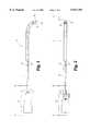
- FIG. 1is a partial cutaway view of a surgical cutting instrument in accordance with a preferred embodiment of the present invention.
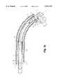
- FIG. 2is a partial cutaway top plan view of the cutting instrument of FIG. 1.
- FIG. 3is a side cross-sectional view of the cutting instrument in FIG. 2, taken along line 3--3 as viewed in the direction of the arrows.
- FIG. 3ais a side cross-sectional view similar to the view in FIG. 3 depicting the cutting instrument with the blade positioned to cut a segment of tissue.
- FIG. 4is a cross-sectional view of the cutting instrument of FIG. 3 taken along line 4--4 as viewed in the direction of the arrows.
- FIG. 5is a top cross-sectional view of the cutting instrument of FIG. 1, taken along line 5--5 as viewed in the direction of the arrows.
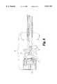
- FIG. 6is a side cross-sectional view of the cutting instrument of FIG. 2, taken along line 6--6 as viewed in the direction of the arrows.
- FIG. 7is a side cross-sectional view of an alternative embodiment of the surgical cutting instrument of the present invention depicting the flexible cable segment of the cutting member.
- FIG. 8is a side cross-sectional view of the handpiece of the cutting instrument of FIG. 7.
- a surgical cutting instrument 10is shown in FIGS. 1 and 2 that is adapted for percutaneous insertion at a surgical site and is specifically adapted to cut tissue in the spinal region.
- the instrument 10includes a handpiece 20 which supports an outer cannula 12.
- the outer cannula 12has an angled distal tip 30 to minimize trauma to tissue as the cutting instrument is manipulated in the surgical site.
- the angled tip 30gently pushes soft tissue aside as the cannula is manipulated to a surgical site. As the cannula 12 is advanced, the tissue will traverse the surface of the angled tip to effectively clear the surgical site of additional tissue.
- the outer cannula 12includes a cutting opening 32 formed therethrough which opens to a central bore 17 extending through the length of the outer cannula 12.
- the cutting opening 32defines a cutting edge 33, which in the preferred embodiment is defined by a beveled cut in the wall of the outer cannula 12. Also in the preferred embodiment, the cutting opening 32 is in the shape of an isosceles triangle.
- the cutting edge 33 in the specific embodimentis defined at the side of the triangle, but excludes the base of the triangular shape as shown in FIG. 1.
- the preferred embodimentfurther includes a sheath 11 axially enclosing the length of the outer cannula 12 extending from the handpiece 20 to a point just prior to the cutting opening 32.
- the outer cannula 12comprises three distinct portions or segments 13,14,15.
- the main body segment 13 of the outer cannula 12extends axially from the handpiece 20, and the distal segment 15 includes the distal tip of the outer cannula 12.
- This distal segment 15is capped at an angle to form the angled tip 30, and also defines the cutting opening 32 of the outer cannula 12.
- the body segment 13is connected to the distal segment 15 by a flexible segment 14 that seals the gap between the two segments 13, 15 and permits the distal segment 15 to move independently of the body segment 13.
- the body segment 13 and the distal segment 15comprise a material more rigid than the flexible segment 14 in order to make the cutting instrument 10 maneuverable within the anatomical space without being so flexible that it cannot be guided to a precise surgical site without use of stiffening means such as a guide wire.
- the flexible segment 14is attached to and creates a fluid-tight seal with the body segment 13 and the distal segment 15 by means of locking grooves 31 contained on these two more rigid segments 13, 15.
- the locking grooves 31 of the present embodimentare a novel advancement over these old techniques.
- the locking grooves 31receive and effectively mate with the flexible segment 14 to effect a more reliable seal and junction between the flexible and rigid segments.
- material from the flexible segment 14fills the grooves 31 to anchor the segment 14 to each of the other segments 13, 15.
- the flexible segment 14is formed of a pliable plastic that is heated at its ends to flow into the grooves 31.
- the outer cannula 12contains an inner cannula or cutting member 16 slidably and concentrically disposed therein.
- This cutting member 16also comprises three distinct segments including a body portion 18, a flexible drive portion 19, and a cutting head portion 40.
- the inner body portion 18corresponds to and is contained within outer body portion 13
- the cutting head portion 40is contained within and corresponds to the internal shape of the distal segment 15, and the flexible drive portion 19, contained within the flexible segment 14, connects the body portion 18 with the cutting head portion 40 in order to permit the cutting head portion 40 to move independently of the body portion 18.
- the flexible drive portion 19comprises at least one driving cable 19A and, as shown in the cross-sectional view of FIG. 4, the preferred embodiment contemplates use of a plurality of driving cables 19A.
- the flexible drive portion 19is pre-bent prior to incorporation in the cutting instrument 10 to provide the cutting instrument 10 with a curved configuration adapted to maneuver more easily through tough tissue than the straight, inflexible reciprocating cutters of the prior art.
- This driving cable 19Amust be stiff enough to effectively transfer the reciprocating force from a reciprocating motor (not shown) engaged through the handpiece, to the cutting head portion 40, but should not be so stiff that it cannot effectively flex within the outer cannula 12.
- the cutting head portion 40 of the inner cannula 16terminates in a cutting edge 43 at an end opening 44 of the inner cannula 16.
- the end opening 44opens into an aspiration passageway 29 that extends through the entire length of the inner cannula 16 and is in fluid communication with the central bore 17 of the outer cannula 12.
- the cutting head portion 40includes a body end 40A and a cutting edge end 40B defined in relation to a hinge slot 41 cut circumferentially around the cutting head portion 40.
- the cutting edge end 40Bis attached to the body end 40A by a hinge segment 42 at the uncut portion of the cutting head segment 40.
- This hinge segment 42is, in essence, a narrow arc segment of a tubular form.
- FIG. 3aOne particular benefit of this configuration for the cutting member 16 is depicted more clearly in FIG. 3a. It is known that as a reciprocating cutter engages and attempts to sever tissue T drawn into the cutting opening 32, the tissue inherently resists the cutting action. As a portion of tissue T 1 is being severed, it exerts a reactive force F against the cutting edge 43 of the cutting member 16. In a typical tube within a tube reciprocating cutter, this reactive or resistive force F is withstood by the cannula without any significant bending or movement of the solid inner cannula. Thus, in prior devices the clearance between the cutting edges remains constant and uncut tissue is thereby permitted to remain in the gap between the inner and outer tubes. Frequently, the tissue is not excised on the first stroke of the cutting blade with these prior devices.
- the present inventionintroduces the hinge slot 41 and the hinge segment 42 to permit the cutting head portion 40 to pivot in the direction of the arrow P in FIG. 3a.
- the cutting member 16advances toward the cutting opening 32 of the outer cannula 12, it maintains a clearance C between the two tubes.
- the cutting head portion 40contacts the tissue T, it pivots so that the cutting edge 43 forms a zero clearance interface with the cutting edge 33 of the outer cannula 12.
- This zero clearance conditioneliminates the gap that typically exists between the cutting edges of prior art devices and facilitates a clean and efficient cut of the tissue segment T 1 to completely sever the tissue between the inner and outer cannulae.
- the excised tissue T 2is then drawn in the direction of the arrow A through the end opening 44 and the aspiration passageway 29 defined through the cutting member 16.
- the cutting opening 32has a width W that is equal to approximately 1/2 an inner diameter D 1 of the outer cannula 12.
- the cutting opening 32is placed as close to the angled tip 30 as possible.
- the outer diameter of the outer cannula 12is preferably less than about 5 mm. Thus, this dimension would dictate a cutting opening width W of about 2.5 mm.
- the cutting head portion 40 of the cutting member 16has a length L which is long enough to allow the entire width of the cutting opening 32 to be occluded at the end of the stroke of the cutting member 16.
- the length L of the cutting head portion 40is a least equal to the cutting opening width W in the outer cannula 12.
- the hinge slot 41 that defines the hinge segment 42extends through about 90% of the inner cannula 16 diameter.
- the hinge segment 42subtends an angle of about 70-80° with a chord length of about one-half a diameter D 2 .
- the hinge segment 42has a length H which is preferably about one-fourth the diameter D 2 of the inner cannula 16.
- the length H of the hinge segment 42must be long enough to permit pivoting of the cutting head portion 40 in the direction P as the tissue is cut, yet strong enough to withstand cyclic bending as the cutting instrument 10 is used.
- the length H of the hinge segment 42is about 0.75 mm for a cutter driven by a motor capable of operation at speeds ranging between 15 to 250 strokes per second.
- the hinge segment 42will flex twice for each cycle as the cutting head portion 40 pivots up to cut and back down to reopen the cutting opening 32 on the return stroke.
- the arc configuration of the hinge segment 42increases its stiffness fatigue resistance.
- outer cannula 12 and the exterior sheath 11are supported by the handpiece 20.
- the exterior sheath 11is attached to a hub 21 of the handpiece 20 by means of a bushing 22, thereby creating a lumen 50 that contains the outer cannula 12 and is in fluid communication with the anatomical space.
- the inner cannula 16extends into the handpiece 20 to engage a drive mount 26 at a cannula support portion 28.
- the drive mount 26is engaged to a drive rod 27 that is connected to a motor or suitable mechanism for providing reciprocating motion (not shown).
- the drive rod 27 and the drive mount 26reciprocate axially in the direction of the arrows R shown in FIG. 6. Since the cutting member 16 is fixed to the drive mount 26, it reciprocates within the outer cannula 12.
- the inner surfaces of the body segment 13 and the distal segment 15 of the outer cannula 12 and the outer surfaces of the body portion 18 and the cutting head portion 40 of the cutting member 16operate as bearing surfaces for the smooth movement of the cutting member 16.
- the handpiece 20includes an aspiration tube 24 that connects the aspiration passageway 29 to a suitable vacuum source (not shown) and tissue collection chamber (not shown) in a manner well known in the art to facilitate aspiration of tissue fragments cut by the combined action of the cutting head portion 40 and the cutting edge 33.
- the handpiecefurther includes an infusion tube 51 that is in fluid communication with the internal lumen 50 to allow external irrigation and lubrication of the outer cannula 12 and of the surgical site.
- the cutting instrument 10incorporates many features of known reciprocating cutters, particularly those cutters implementing the "tube within a tube” approach.
- these prior cuttersare inherently limited in the type of tissues that can be cut and in the cutting speeds at which they are capable of operating.
- the present inventionincorporates the novel feature of a flexible drive portion 19 which allows the cutting instrument 10 to navigate through while still maintaining the minimally invasive dimensions demanded for percutaneous or intratrocar insertion.
- FIGS. 7 and 8An alternative embodiment of the surgical cutting instrument of the present invention is shown in FIGS. 7 and 8.
- an outer cannula 60is provided which is substantially similar in construction to the outer cannula 12 previously described.
- a handpiece 70is provided for supporting the outer cannula 60.
- the cutting member 61 of this embodimentis modified somewhat from the previous embodiment.
- This alternate configurationincludes a cutting head portion 62 that is sized and shaped similar to the cutting head portion 40 of the embodiment in FIGS. 1, 2, and 3; however, the flexible drive portion of this cutting member 61 is extended through most of the length of the cutting member to define a flexible drive body 63.
- the flexible drive body 63replaces the tubular body portion 18 of the previous embodiment and extends from its attachment at the cutting head portion 62 to a point of engagement with a drive mount 71 (FIG. 8) which is itself engaged to a drive rod 72 to provide axial reciprocating movement to the cutting head portion 62.
- the handpiece 70defines an aspiration tube 73 which is connected to a vacuum source. The aspiration tube 73 opens directly into the interior of the outer cannula 60, thereby providing a greater aspiration flow path than is attainable through the inner cannula 16 of the previous embodiment.
- the cutting member 61includes a full cylindrical segment only at the cutting head portion 62.
- the cutting head portion 62will exhibit the same pivoting capability about the flexible drive body 63 as the previous embodiment.
- the reduced profile of the cutting member 61 throughout most of its lengthachieved by using flexible driving cables in the preferred embodiment of the flexible drive body 63, reduces the sliding friction between the cutting member 61 and the outer cannula 60.
- This embodimentretains the benefit of pivoting a cutting edge of the cutting head portion 62 to attain zero clearance with a cutting opening of the outer cannula 60 as the tissue is being excised.
- a smaller motorcan be used to drive the entire cutting assembly. This specific embodiment is preferably reserved for use on less rigorous tissue.
- each of the cutting componentsare formed of stainless steel, preferably 304SS typically used in medical grade components. It is also preferred that the flexible segment 14 be formed of a flexible material such as plastic or rubber, and most preferably the flexible material comprises low density polyethylene (LDPE).
- LDPElow density polyethylene
- the outer sheath 11is preferably composed of a medical grade material and is sized for percutaneous insertion into the same anatomical spaces as will accommodate the preferred embodiments of the present invention.
- the outer sheath 11may be curved, bent, or straight, depending upon the particular application for which the cutting instrument is used.
- This inventioncontemplates a reciprocating cutting instrument having a flexible portion and a hinged cutting head portion, wherein flexible drive means transfers the reciprocating force to the hinged cutting head portion.
- flexible drive portionas encompassing a plurality of stiff driving cables, alternate drive means such as single cables or wires, carbon fiber cables, or pneumatic means are also contemplated by and intended to come within the scope of the present invention.
Landscapes
- Health & Medical Sciences (AREA)
- Surgery (AREA)
- Life Sciences & Earth Sciences (AREA)
- Biomedical Technology (AREA)
- Nuclear Medicine, Radiotherapy & Molecular Imaging (AREA)
- Engineering & Computer Science (AREA)
- Orthopedic Medicine & Surgery (AREA)
- Heart & Thoracic Surgery (AREA)
- Medical Informatics (AREA)
- Molecular Biology (AREA)
- Animal Behavior & Ethology (AREA)
- General Health & Medical Sciences (AREA)
- Public Health (AREA)
- Veterinary Medicine (AREA)
- Surgical Instruments (AREA)
Abstract
Description
Claims (13)
Priority Applications (1)
| Application Number | Priority Date | Filing Date | Title |
|---|---|---|---|
| US09/015,832US5911701A (en) | 1998-01-29 | 1998-01-29 | Surgical cutting instrument |
Applications Claiming Priority (1)
| Application Number | Priority Date | Filing Date | Title |
|---|---|---|---|
| US09/015,832US5911701A (en) | 1998-01-29 | 1998-01-29 | Surgical cutting instrument |
Publications (1)
| Publication Number | Publication Date |
|---|---|
| US5911701Atrue US5911701A (en) | 1999-06-15 |
Family
ID=21773888
Family Applications (1)
| Application Number | Title | Priority Date | Filing Date |
|---|---|---|---|
| US09/015,832Expired - LifetimeUS5911701A (en) | 1998-01-29 | 1998-01-29 | Surgical cutting instrument |
Country Status (1)
| Country | Link |
|---|---|
| US (1) | US5911701A (en) |
Cited By (91)
| Publication number | Priority date | Publication date | Assignee | Title |
|---|---|---|---|---|
| US6322536B1 (en)* | 1998-03-06 | 2001-11-27 | Cornell Research Foundation, Inc. | Minimally invasive gene therapy delivery and method |
| US6419641B1 (en) | 2000-11-28 | 2002-07-16 | Promex, Llc | Flexible tip medical instrument |
| US20030037628A1 (en)* | 2001-08-23 | 2003-02-27 | Remy Chave | Device for converting straight-line motion to rotary motion |
| US6638235B2 (en) | 2000-11-06 | 2003-10-28 | Suros Surgical Systems, Inc. | Biopsy apparatus |
| US20040016438A1 (en)* | 2002-07-26 | 2004-01-29 | Han Jong Sam | Hand piece for removing the calluses of the skin |
| US20040049128A1 (en)* | 2000-11-06 | 2004-03-11 | Miller Michael E. | Biopsy apparatus |
| US20050197661A1 (en)* | 2004-03-03 | 2005-09-08 | Scimed Life Systems, Inc. | Tissue removal probe with sliding burr in cutting window |
| US20050209622A1 (en)* | 2004-03-03 | 2005-09-22 | Scimed Life Systems, Inc. | Tissue removal probe with irrigation and aspiration ports |
| US20060149267A1 (en)* | 2004-12-22 | 2006-07-06 | John Nordt | Safety knife for resection of annulus |
| US20060241665A1 (en)* | 2005-04-08 | 2006-10-26 | Vance Products Incorporated, D/B/A Cook Urological Incorporated | Percutaneous and endoscopic cutters |
| US20060260994A1 (en)* | 2005-05-18 | 2006-11-23 | Mark Joseph L | Selectively openable tissue filter |
| US20070010738A1 (en)* | 2004-10-14 | 2007-01-11 | Mark Joseph L | Surgical site marker delivery system |
| US20070055259A1 (en)* | 2005-08-17 | 2007-03-08 | Norton Britt K | Apparatus and methods for removal of intervertebral disc tissues |
| US20070149975A1 (en)* | 2005-11-29 | 2007-06-28 | Oliver Dana A | Method and apparatus for removing material from an intervertebral disc space, such as in performing a nucleotomy |
| US20070162062A1 (en)* | 2005-12-08 | 2007-07-12 | Norton Britt K | Reciprocating apparatus and methods for removal of intervertebral disc tissues |
| US20070243657A1 (en)* | 2006-04-13 | 2007-10-18 | Basol Bulent M | Method and Apparatus to Form Thin Layers of Materials on a Base |
| US20070260249A1 (en)* | 2005-12-28 | 2007-11-08 | Thomas Boyajian | Devices and methods for bone anchoring |
| US7458940B2 (en) | 2000-11-06 | 2008-12-02 | Suros Surgical Systems, Inc. | Biopsy apparatus |
| EP1901666A4 (en)* | 2005-07-11 | 2010-01-06 | Kyphon Inc | Apparatus and methods of tissue removal within a spine |
| US20100023042A1 (en)* | 2007-02-02 | 2010-01-28 | Synthes (U.S.A.) | Tunnel Tool for Soft Tissue |
| US7670328B2 (en) | 2002-05-31 | 2010-03-02 | Vidacare Corporation | Apparatus and method to provide emergency access to bone marrow |
| US20100057143A1 (en)* | 1999-08-18 | 2010-03-04 | Intrinsic Therapeutics, Inc. | Interior and exterior support system for intervertebral disc repair |
| US20100152614A1 (en)* | 2008-12-16 | 2010-06-17 | Mark Joseph L | Tissue removal device for neurosurgical and spinal surgery applications |
| US20100152761A1 (en)* | 2008-12-16 | 2010-06-17 | Mark Joseph L | Tissue removal device for neurosurgical and spinal surgery applications |
| US20100152615A1 (en)* | 2008-12-16 | 2010-06-17 | Mark Joseph L | Tissue removal device with adjustable fluid supply sleeve for neurosurgical and spinal surgery applications |
| US20100152762A1 (en)* | 2008-12-16 | 2010-06-17 | Mark Joseph L | Tissue removal system with multi-directional foot actuator assembly for neurosurgical and spinal surgery applications |
| US20100152760A1 (en)* | 2008-12-16 | 2010-06-17 | Mark Joseph L | Tissue removal device for neurosurgical and spinal surgery applications |
| US20100152758A1 (en)* | 2008-12-16 | 2010-06-17 | Mark Joseph L | Tissue removal device for neurosurgical and spinal surgery applications |
| US20100152533A1 (en)* | 2008-12-16 | 2010-06-17 | Mark Joseph L | Tissue removal device for use with imaging devices in neurosurgical and spinal surgery applications |
| US20100152756A1 (en)* | 2008-12-16 | 2010-06-17 | Mark Joseph L | Tissue removal device for neurosurgical and spinal surgery applications |
| US20100160818A1 (en)* | 2005-04-12 | 2010-06-24 | Ethicon Endo-Surgery, Inc. | MRI Biopsy Device |
| US20100160777A1 (en)* | 2008-12-22 | 2010-06-24 | Hardin Terry D | Reverse deployment device |
| US20100249817A1 (en)* | 2008-12-16 | 2010-09-30 | Mark Joseph L | Positioning system for tissue removal device |
| US7811260B2 (en) | 2002-05-31 | 2010-10-12 | Vidacare Corporation | Apparatus and method to inject fluids into bone marrow and other target sites |
| US7815642B2 (en) | 2004-01-26 | 2010-10-19 | Vidacare Corporation | Impact-driven intraosseous needle |
| US7850620B2 (en) | 2002-05-31 | 2010-12-14 | Vidacare Corporation | Biopsy devices and related methods |
| US20110004119A1 (en)* | 2009-07-01 | 2011-01-06 | Michael Hoffa | Surgical system |
| US20110125271A1 (en)* | 1999-08-18 | 2011-05-26 | Intrinsic Therapeutics, Inc. | Method of performing an anchor implantation procedure within a disc |
| US7951089B2 (en) | 2002-05-31 | 2011-05-31 | Vidacare Corporation | Apparatus and methods to harvest bone and bone marrow |
| US7959679B2 (en) | 1999-08-18 | 2011-06-14 | Intrinsic Therapeutics, Inc. | Intervertebral anulus and nucleus augmentation |
| US7988642B2 (en) | 2003-10-14 | 2011-08-02 | Suros Surgical Systems, Inc. | Vacuum assisted biopsy device |
| US20110196492A1 (en)* | 2007-09-07 | 2011-08-11 | Intrinsic Therapeutics, Inc. | Bone anchoring systems |
| US8021425B2 (en) | 1999-08-18 | 2011-09-20 | Intrinsic Therapeutics, Inc. | Versatile method of repairing an intervertebral disc |
| US8048003B2 (en) | 2003-10-14 | 2011-11-01 | Suros Surgical Systems, Inc. | Vacuum assisted biopsy device |
| WO2011151039A1 (en)* | 2010-06-01 | 2011-12-08 | Hipp Medical Ag | Joint biopsy needle for taking tissue samples |
| US8142365B2 (en) | 2002-05-31 | 2012-03-27 | Vidacare Corporation | Apparatus and method for accessing the bone marrow of the sternum |
| US8187204B2 (en) | 2007-10-01 | 2012-05-29 | Suros Surgical Systems, Inc. | Surgical device and method for using same |
| US8231544B2 (en) | 2003-10-14 | 2012-07-31 | Suros Surgical Systems, Inc. | Vacuum assisted biopsy needle set |
| US8231678B2 (en) | 1999-08-18 | 2012-07-31 | Intrinsic Therapeutics, Inc. | Method of treating a herniated disc |
| US20120221033A1 (en)* | 2011-02-28 | 2012-08-30 | Jack Robert Auld | Surgical probe with increased fluid flow |
| US8323341B2 (en) | 2007-09-07 | 2012-12-04 | Intrinsic Therapeutics, Inc. | Impaction grafting for vertebral fusion |
| WO2012060959A3 (en)* | 2010-11-03 | 2013-03-14 | Gyrus Ent, L.L.C. | Surgical tool with sheath |
| US8414606B2 (en) | 2010-10-22 | 2013-04-09 | Medtronic Xomed, Inc. | Method and apparatus for removing material from an intervertebral disc space and preparing end plates |
| US8419683B2 (en) | 2004-11-12 | 2013-04-16 | Vidacare Corporation | Intraosseous device and methods for accessing bone marrow in the sternum and other target areas |
| US8465471B2 (en) | 2009-08-05 | 2013-06-18 | Rocin Laboratories, Inc. | Endoscopically-guided electro-cauterizing power-assisted fat aspiration system for aspirating visceral fat tissue within the abdomen of a patient |
| US8641715B2 (en) | 2002-05-31 | 2014-02-04 | Vidacare Corporation | Manual intraosseous device |
| US8656929B2 (en) | 2002-05-31 | 2014-02-25 | Vidacare Corporation | Medical procedures trays and related methods |
| US8668698B2 (en) | 2002-05-31 | 2014-03-11 | Vidacare Corporation | Assembly for coupling powered driver with intraosseous device |
| US8690791B2 (en) | 2002-05-31 | 2014-04-08 | Vidacare Corporation | Apparatus and method to access the bone marrow |
| US8790361B2 (en) | 2012-05-23 | 2014-07-29 | Depuy Mitek, Llc | Methods and devices for cutting and removing tissue from a body |
| US8808200B2 (en) | 2007-10-01 | 2014-08-19 | Suros Surgical Systems, Inc. | Surgical device and method of using same |
| US20140276744A1 (en)* | 2013-03-15 | 2014-09-18 | Kyphon Sarl | Surgical cutting device |
| US20150005753A1 (en)* | 2012-03-05 | 2015-01-01 | Wake Forest University Health Sciences | Medical tools with aspiration tips suitable for cataract surgeries and related methods |
| US8944069B2 (en) | 2006-09-12 | 2015-02-03 | Vidacare Corporation | Assemblies for coupling intraosseous (IO) devices to powered drivers |
| US8974410B2 (en) | 2006-10-30 | 2015-03-10 | Vidacare LLC | Apparatus and methods to communicate fluids and/or support intraosseous devices |
| US9066814B2 (en) | 2010-08-02 | 2015-06-30 | Ulrich Medical Usa, Inc. | Implant assembly having an angled head |
| US9072543B2 (en) | 2002-05-31 | 2015-07-07 | Vidacare LLC | Vascular access kits and methods |
| US20150335485A1 (en)* | 2013-02-04 | 2015-11-26 | Geuder Ag | Device for cutting and aspirating tissue |
| US9279751B2 (en) | 2008-12-16 | 2016-03-08 | Nico Corporation | System and method of taking and collecting tissue cores for treatment |
| US9314228B2 (en) | 2002-05-31 | 2016-04-19 | Vidacare LLC | Apparatus and method for accessing the bone marrow |
| US9433400B2 (en) | 2004-01-26 | 2016-09-06 | Vidacare LLC | Manual intraosseous device |
| US9439667B2 (en) | 2002-05-31 | 2016-09-13 | Vidacare LLC | Apparatus and methods to install, support and/or monitor performance of intraosseous devices |
| US9451968B2 (en) | 2002-05-31 | 2016-09-27 | Vidacare LLC | Powered drivers, intraosseous devices and methods to access bone marrow |
| US9504477B2 (en) | 2003-05-30 | 2016-11-29 | Vidacare LLC | Powered driver |
| US9504247B2 (en) | 2008-12-16 | 2016-11-29 | Nico Corporation | System for collecting and preserving tissue cores |
| US9510910B2 (en) | 2006-09-12 | 2016-12-06 | Vidacare LLC | Medical procedures trays and related methods |
| US9545243B2 (en) | 2002-05-31 | 2017-01-17 | Vidacare LLC | Bone marrow aspiration devices and related methods |
| US9638770B2 (en) | 2004-05-21 | 2017-05-02 | Devicor Medical Products, Inc. | MRI biopsy apparatus incorporating an imageable penetrating portion |
| US9795365B2 (en) | 2004-05-21 | 2017-10-24 | Devicor Medical Products, Inc. | MRI biopsy apparatus incorporating a sleeve and multi-function obturator |
| US9820480B2 (en) | 2008-12-16 | 2017-11-21 | Nico Corporation | System for collecting and preserving tissue cores |
| US9925314B2 (en) | 2009-08-05 | 2018-03-27 | Rocin Laboratories, Inc. | Method of performing intra-abdominal tissue aspiration to ameliorate the metabolic syndrome, or abdominal obesity |
| US9931105B2 (en) | 2008-12-16 | 2018-04-03 | Nico Corporation | System and method of taking and collecting tissue cores for treatment |
| WO2018067808A1 (en)* | 2016-10-05 | 2018-04-12 | The Trustees Of The University Of Pennsylvania | Sharp turning steerable needle |
| US20180250165A1 (en)* | 2015-09-01 | 2018-09-06 | Mani, Inc. | Vitreous body surgical probe |
| US10080578B2 (en) | 2008-12-16 | 2018-09-25 | Nico Corporation | Tissue removal device with adjustable delivery sleeve for neurosurgical and spinal surgery applications |
| US10368890B2 (en) | 2008-12-16 | 2019-08-06 | Nico Corporation | Multi-functional surgical device for neurosurgical and spinal surgery applications |
| CN112617937A (en)* | 2020-12-29 | 2021-04-09 | 美科特医疗科技(苏州)有限公司 | Anastomat sleeve pipe assembly |
| US10973545B2 (en) | 2002-05-31 | 2021-04-13 | Teleflex Life Sciences Limited | Powered drivers, intraosseous devices and methods to access bone marrow |
| US10973532B2 (en) | 2002-05-31 | 2021-04-13 | Teleflex Life Sciences Limited | Powered drivers, intraosseous devices and methods to access bone marrow |
| US11298202B2 (en) | 2002-05-31 | 2022-04-12 | Teleflex Life Sciences Limited | Biopsy devices and related methods |
| US11337728B2 (en) | 2002-05-31 | 2022-05-24 | Teleflex Life Sciences Limited | Powered drivers, intraosseous devices and methods to access bone marrow |
Citations (10)
| Publication number | Priority date | Publication date | Assignee | Title |
|---|---|---|---|---|
| US3815604A (en)* | 1972-06-19 | 1974-06-11 | Malley C O | Apparatus for intraocular surgery |
| US3964468A (en)* | 1975-05-30 | 1976-06-22 | The Board Of Trustees Of Leland Stanford Junior University | Bioptome |
| US4011869A (en)* | 1975-08-01 | 1977-03-15 | David Kopf Instruments | Tubular cutting instrument |
| US4203444A (en)* | 1977-11-07 | 1980-05-20 | Dyonics, Inc. | Surgical instrument suitable for closed surgery such as of the knee |
| US4246902A (en)* | 1978-03-10 | 1981-01-27 | Miguel Martinez | Surgical cutting instrument |
| US4781186A (en)* | 1984-05-30 | 1988-11-01 | Devices For Vascular Intervention, Inc. | Atherectomy device having a flexible housing |
| US4819635A (en)* | 1987-09-18 | 1989-04-11 | Henry Shapiro | Tubular microsurgery cutting apparatus |
| US4911161A (en)* | 1987-04-29 | 1990-03-27 | Noetix, Inc. | Capsulectomy cutting apparatus |
| US5106364A (en)* | 1989-07-07 | 1992-04-21 | Kabushiki Kaisha Topcon | Surgical cutter |
| US5226910A (en)* | 1989-07-05 | 1993-07-13 | Kabushiki Kaisha Topcon | Surgical cutter |
- 1998
- 1998-01-29USUS09/015,832patent/US5911701A/ennot_activeExpired - Lifetime
Patent Citations (11)
| Publication number | Priority date | Publication date | Assignee | Title |
|---|---|---|---|---|
| US3815604A (en)* | 1972-06-19 | 1974-06-11 | Malley C O | Apparatus for intraocular surgery |
| US3964468A (en)* | 1975-05-30 | 1976-06-22 | The Board Of Trustees Of Leland Stanford Junior University | Bioptome |
| US4011869A (en)* | 1975-08-01 | 1977-03-15 | David Kopf Instruments | Tubular cutting instrument |
| US4203444A (en)* | 1977-11-07 | 1980-05-20 | Dyonics, Inc. | Surgical instrument suitable for closed surgery such as of the knee |
| US4203444B1 (en)* | 1977-11-07 | 1987-07-21 | ||
| US4246902A (en)* | 1978-03-10 | 1981-01-27 | Miguel Martinez | Surgical cutting instrument |
| US4781186A (en)* | 1984-05-30 | 1988-11-01 | Devices For Vascular Intervention, Inc. | Atherectomy device having a flexible housing |
| US4911161A (en)* | 1987-04-29 | 1990-03-27 | Noetix, Inc. | Capsulectomy cutting apparatus |
| US4819635A (en)* | 1987-09-18 | 1989-04-11 | Henry Shapiro | Tubular microsurgery cutting apparatus |
| US5226910A (en)* | 1989-07-05 | 1993-07-13 | Kabushiki Kaisha Topcon | Surgical cutter |
| US5106364A (en)* | 1989-07-07 | 1992-04-21 | Kabushiki Kaisha Topcon | Surgical cutter |
Cited By (223)
| Publication number | Priority date | Publication date | Assignee | Title |
|---|---|---|---|---|
| US6322536B1 (en)* | 1998-03-06 | 2001-11-27 | Cornell Research Foundation, Inc. | Minimally invasive gene therapy delivery and method |
| US8257437B2 (en) | 1999-08-18 | 2012-09-04 | Intrinsic Therapeutics, Inc. | Methods of intervertebral disc augmentation |
| US8409284B2 (en) | 1999-08-18 | 2013-04-02 | Intrinsic Therapeutics, Inc. | Methods of repairing herniated segments in the disc |
| US20110125271A1 (en)* | 1999-08-18 | 2011-05-26 | Intrinsic Therapeutics, Inc. | Method of performing an anchor implantation procedure within a disc |
| US9706947B2 (en) | 1999-08-18 | 2017-07-18 | Intrinsic Therapeutics, Inc. | Method of performing an anchor implantation procedure within a disc |
| US20100057143A1 (en)* | 1999-08-18 | 2010-03-04 | Intrinsic Therapeutics, Inc. | Interior and exterior support system for intervertebral disc repair |
| US7959679B2 (en) | 1999-08-18 | 2011-06-14 | Intrinsic Therapeutics, Inc. | Intervertebral anulus and nucleus augmentation |
| US7998213B2 (en) | 1999-08-18 | 2011-08-16 | Intrinsic Therapeutics, Inc. | Intervertebral disc herniation repair |
| US8002836B2 (en) | 1999-08-18 | 2011-08-23 | Intrinsic Therapeutics, Inc. | Method for the treatment of the intervertebral disc anulus |
| US8021425B2 (en) | 1999-08-18 | 2011-09-20 | Intrinsic Therapeutics, Inc. | Versatile method of repairing an intervertebral disc |
| US9333087B2 (en) | 1999-08-18 | 2016-05-10 | Intrinsic Therapeutics, Inc. | Herniated disc repair |
| US8025698B2 (en) | 1999-08-18 | 2011-09-27 | Intrinsic Therapeutics, Inc. | Method of rehabilitating an anulus fibrosus |
| US8105384B2 (en) | 1999-08-18 | 2012-01-31 | Intrinsic Therapeutics, Inc. | Weakened anulus repair |
| US8231678B2 (en) | 1999-08-18 | 2012-07-31 | Intrinsic Therapeutics, Inc. | Method of treating a herniated disc |
| US8568332B2 (en) | 2000-11-06 | 2013-10-29 | Suros Surgical Systems, Inc. | Biopsy apparatus |
| US8986222B2 (en) | 2000-11-06 | 2015-03-24 | Hologic, Inc. | Biopsy apparatus |
| US7883476B2 (en) | 2000-11-06 | 2011-02-08 | Suros Surgical Systems, Inc. | Selectively detachable outer cannula hub |
| US7837630B2 (en) | 2000-11-06 | 2010-11-23 | Suros Surgical Systems, Inc. | Fluid control element for biopsy apparatus |
| US20060155209A1 (en)* | 2000-11-06 | 2006-07-13 | Miller Michael E | Selectively detachable outer cannula hub |
| US6638235B2 (en) | 2000-11-06 | 2003-10-28 | Suros Surgical Systems, Inc. | Biopsy apparatus |
| US8277393B2 (en) | 2000-11-06 | 2012-10-02 | Suros Surgical Systems, Inc. | Biopsy apparatus |
| US8167818B2 (en) | 2000-11-06 | 2012-05-01 | Suros Surgical Systems, Inc. | Biopsy apparatus with vacuum relief |
| US8764679B2 (en) | 2000-11-06 | 2014-07-01 | Suros Surgical Systems, Inc. | Biopsy apparatus |
| US8192370B2 (en) | 2000-11-06 | 2012-06-05 | Suros Surgical Systems, Inc. | Biopsy apparatus |
| US20070027407A1 (en)* | 2000-11-06 | 2007-02-01 | Suros Surgical Systems, Inc. | Biopsy apparatus with vacuum relief |
| US8109886B2 (en) | 2000-11-06 | 2012-02-07 | Suros Surgical Systems, Inc. | Biopsy apparatus |
| US20060129062A1 (en)* | 2000-11-06 | 2006-06-15 | Nicoson Zachary R | Fluid control element for biopsy apparatus |
| US20040049128A1 (en)* | 2000-11-06 | 2004-03-11 | Miller Michael E. | Biopsy apparatus |
| US7458940B2 (en) | 2000-11-06 | 2008-12-02 | Suros Surgical Systems, Inc. | Biopsy apparatus |
| US20090048533A1 (en)* | 2000-11-06 | 2009-02-19 | Miller Michael E | Biopsy apparatus |
| US7497833B2 (en) | 2000-11-06 | 2009-03-03 | Suros Surgical Systems, Inc. | Biopsy apparatus with vacuum relief |
| US20090137927A1 (en)* | 2000-11-06 | 2009-05-28 | Miller Michael E | Biopsy apparatus with vacuum relief |
| US20050113715A1 (en)* | 2000-11-06 | 2005-05-26 | Jeffrey Schwindt | Biopsy apparatus |
| US20050049521A1 (en)* | 2000-11-06 | 2005-03-03 | Suros Surgical Systems, Inc. | Collection filter for biopsy apparatus |
| US20040267157A1 (en)* | 2000-11-06 | 2004-12-30 | Miller Michael E | Biopsy apparatus |
| US6758824B1 (en) | 2000-11-06 | 2004-07-06 | Suros Surgical Systems, Inc. | Biopsy apparatus |
| US20060184153A1 (en)* | 2000-11-28 | 2006-08-17 | Promex Technologies, Llc | Flexible tip medical instrument |
| US6419641B1 (en) | 2000-11-28 | 2002-07-16 | Promex, Llc | Flexible tip medical instrument |
| US7841990B2 (en) | 2000-11-28 | 2010-11-30 | Promex Technologies, Llc | Flexible tip medical instrument |
| US20030037628A1 (en)* | 2001-08-23 | 2003-02-27 | Remy Chave | Device for converting straight-line motion to rotary motion |
| US8684978B2 (en) | 2002-05-31 | 2014-04-01 | Vidacare Corporation | Apparatus and method to inject fluids into bone marrow and other target sites |
| US8142365B2 (en) | 2002-05-31 | 2012-03-27 | Vidacare Corporation | Apparatus and method for accessing the bone marrow of the sternum |
| US9314228B2 (en) | 2002-05-31 | 2016-04-19 | Vidacare LLC | Apparatus and method for accessing the bone marrow |
| US9295487B2 (en) | 2002-05-31 | 2016-03-29 | Vidacare LLC | Apparatus and method to inject fluids into bone marrow and other target sites |
| US8668698B2 (en) | 2002-05-31 | 2014-03-11 | Vidacare Corporation | Assembly for coupling powered driver with intraosseous device |
| US8656929B2 (en) | 2002-05-31 | 2014-02-25 | Vidacare Corporation | Medical procedures trays and related methods |
| US9393031B2 (en) | 2002-05-31 | 2016-07-19 | Vidacare LLC | Apparatus and method to provide emergency access to bone marrow |
| US10166332B2 (en) | 2002-05-31 | 2019-01-01 | Teleflex Medical Devices S.À R.L. | Apparatus to inject fluids into bone marrow and other target sites |
| US11337728B2 (en) | 2002-05-31 | 2022-05-24 | Teleflex Life Sciences Limited | Powered drivers, intraosseous devices and methods to access bone marrow |
| US11324521B2 (en) | 2002-05-31 | 2022-05-10 | Teleflex Life Sciences Limited | Apparatus and method to access bone marrow |
| US7811260B2 (en) | 2002-05-31 | 2010-10-12 | Vidacare Corporation | Apparatus and method to inject fluids into bone marrow and other target sites |
| US8641715B2 (en) | 2002-05-31 | 2014-02-04 | Vidacare Corporation | Manual intraosseous device |
| US11298202B2 (en) | 2002-05-31 | 2022-04-12 | Teleflex Life Sciences Limited | Biopsy devices and related methods |
| US11291472B2 (en) | 2002-05-31 | 2022-04-05 | Teleflex Life Sciences Limited | Powered drivers, intraosseous devices and methods to access bone marrow |
| US7850620B2 (en) | 2002-05-31 | 2010-12-14 | Vidacare Corporation | Biopsy devices and related methods |
| US11266441B2 (en) | 2002-05-31 | 2022-03-08 | Teleflex Life Sciences Limited | Penetrator assembly for accessing bone marrow |
| US9439667B2 (en) | 2002-05-31 | 2016-09-13 | Vidacare LLC | Apparatus and methods to install, support and/or monitor performance of intraosseous devices |
| US9451968B2 (en) | 2002-05-31 | 2016-09-27 | Vidacare LLC | Powered drivers, intraosseous devices and methods to access bone marrow |
| US7699850B2 (en) | 2002-05-31 | 2010-04-20 | Vidacare Corporation | Apparatus and method to access bone marrow |
| US7951089B2 (en) | 2002-05-31 | 2011-05-31 | Vidacare Corporation | Apparatus and methods to harvest bone and bone marrow |
| US7670328B2 (en) | 2002-05-31 | 2010-03-02 | Vidacare Corporation | Apparatus and method to provide emergency access to bone marrow |
| US10245010B2 (en) | 2002-05-31 | 2019-04-02 | Teleflex Medical Devices S.A.R.L | Assembly for coupling powered driver with intraosseous device |
| US9078637B2 (en) | 2002-05-31 | 2015-07-14 | Vidacare LLC | Apparatus and methods to harvest bone and bone marrow |
| US8690791B2 (en) | 2002-05-31 | 2014-04-08 | Vidacare Corporation | Apparatus and method to access the bone marrow |
| US11234683B2 (en) | 2002-05-31 | 2022-02-01 | Teleflex Life Sciences Limited | Assembly for coupling powered driver with intraosseous device |
| US9072543B2 (en) | 2002-05-31 | 2015-07-07 | Vidacare LLC | Vascular access kits and methods |
| US8506568B2 (en) | 2002-05-31 | 2013-08-13 | Vidacare Corporation | Apparatus and method to access bone marrow |
| US8992535B2 (en) | 2002-05-31 | 2015-03-31 | Vidacare LLC | Apparatus and method to provide emergency access to bone marrow |
| US10413282B2 (en) | 2002-05-31 | 2019-09-17 | Teleflex Medical Devices S.Àr.L. | Apparatus and methods to harvest bone and bone marrow |
| US8038664B2 (en) | 2002-05-31 | 2011-10-18 | Vidacare Corporation | Apparatus and method to inject fluids into bone marrow and other target sites |
| US8480632B2 (en) | 2002-05-31 | 2013-07-09 | Vidacare Corporation | Cartridge apparatus for injecting fluids into bone |
| US10456149B2 (en) | 2002-05-31 | 2019-10-29 | Teleflex Medical Devices S.À R.L. | Apparatus and method to access bone marrow |
| US9545243B2 (en) | 2002-05-31 | 2017-01-17 | Vidacare LLC | Bone marrow aspiration devices and related methods |
| US8715287B2 (en) | 2002-05-31 | 2014-05-06 | Vidacare Corporation | Apparatus and method to provide emergency access to bone marrow |
| US8876826B2 (en) | 2002-05-31 | 2014-11-04 | Vidacare Corporation | Apparatus and method to access bone marrow |
| US10492830B2 (en) | 2002-05-31 | 2019-12-03 | Teleflex Medical Devices S.À R.L. | Penetrator assembly for accessing bone marrow |
| US10512474B2 (en) | 2002-05-31 | 2019-12-24 | Teleflex Medical Devices S.À R.L. | Powered drivers, intraosseous devices and methods to access bone marrow |
| US11103282B1 (en) | 2002-05-31 | 2021-08-31 | Teleflex Life Sciences Limited | Powered drivers, intraosseous devices and methods to access bone marrow |
| US10016217B2 (en) | 2002-05-31 | 2018-07-10 | Teleflex Medical Devices S.À.R.L. | Apparatus and methods to install, support and/or monitor performance of intraosseous devices |
| US11103281B2 (en) | 2002-05-31 | 2021-08-31 | Teleflex Life Sciences Limited | Apparatus and methods to install, support and/or monitor performance of intraosseous devices |
| US9314270B2 (en) | 2002-05-31 | 2016-04-19 | Vidacare LLC | Apparatus and method to access bone marrow |
| US9717847B2 (en) | 2002-05-31 | 2017-08-01 | Teleflex Medical Devices S.Àr.L. | Apparatus and method to inject fluids into bone marrow and other target sites |
| US11065382B2 (en) | 2002-05-31 | 2021-07-20 | Teleflex Life Sciences Limited | Apparatus to inject fluids into bone marrow and other target sites |
| US10595896B2 (en) | 2002-05-31 | 2020-03-24 | Teleflex Life Sciences Limited | Apparatus for accessing bone marrow including depth control mechanism |
| US9872703B2 (en) | 2002-05-31 | 2018-01-23 | Teleflex Medical Devices S.Àr.L. | Vascular access kits and methods |
| US8308693B2 (en) | 2002-05-31 | 2012-11-13 | Vidacare Corporation | Bone penetrating needle with angled ports |
| US10973532B2 (en) | 2002-05-31 | 2021-04-13 | Teleflex Life Sciences Limited | Powered drivers, intraosseous devices and methods to access bone marrow |
| US10973545B2 (en) | 2002-05-31 | 2021-04-13 | Teleflex Life Sciences Limited | Powered drivers, intraosseous devices and methods to access bone marrow |
| US10893875B2 (en) | 2002-05-31 | 2021-01-19 | Teleflex Life Sciences Limited | Apparatus to access bone marrow |
| US10806491B2 (en) | 2002-05-31 | 2020-10-20 | Teleflex Life Sciences Limited | Vascular access kits and methods |
| US20040016438A1 (en)* | 2002-07-26 | 2004-01-29 | Han Jong Sam | Hand piece for removing the calluses of the skin |
| US7093603B2 (en)* | 2002-07-26 | 2006-08-22 | Oxyvac Medical Instrument Co., Ltd. | Hand piece for removing the calluses of the skin |
| US9504477B2 (en) | 2003-05-30 | 2016-11-29 | Vidacare LLC | Powered driver |
| US10052111B2 (en) | 2003-05-30 | 2018-08-21 | Teleflex Medical Devices S.À R.L. | Powered driver |
| US8430827B2 (en) | 2003-10-14 | 2013-04-30 | Suros Surgical Sysytems, Inc. | Vacuum assisted biopsy device |
| US7988642B2 (en) | 2003-10-14 | 2011-08-02 | Suros Surgical Systems, Inc. | Vacuum assisted biopsy device |
| US8231544B2 (en) | 2003-10-14 | 2012-07-31 | Suros Surgical Systems, Inc. | Vacuum assisted biopsy needle set |
| US8048003B2 (en) | 2003-10-14 | 2011-11-01 | Suros Surgical Systems, Inc. | Vacuum assisted biopsy device |
| US8870872B2 (en) | 2004-01-26 | 2014-10-28 | Vidacare Corporation | Impact-driven intraosseous needle |
| US9433400B2 (en) | 2004-01-26 | 2016-09-06 | Vidacare LLC | Manual intraosseous device |
| US7815642B2 (en) | 2004-01-26 | 2010-10-19 | Vidacare Corporation | Impact-driven intraosseous needle |
| US20050209622A1 (en)* | 2004-03-03 | 2005-09-22 | Scimed Life Systems, Inc. | Tissue removal probe with irrigation and aspiration ports |
| US20050197661A1 (en)* | 2004-03-03 | 2005-09-08 | Scimed Life Systems, Inc. | Tissue removal probe with sliding burr in cutting window |
| US9504453B2 (en) | 2004-05-21 | 2016-11-29 | Devicor Medical Products, Inc. | MRI biopsy device |
| US9795365B2 (en) | 2004-05-21 | 2017-10-24 | Devicor Medical Products, Inc. | MRI biopsy apparatus incorporating a sleeve and multi-function obturator |
| US8932233B2 (en) | 2004-05-21 | 2015-01-13 | Devicor Medical Products, Inc. | MRI biopsy device |
| US9638770B2 (en) | 2004-05-21 | 2017-05-02 | Devicor Medical Products, Inc. | MRI biopsy apparatus incorporating an imageable penetrating portion |
| US9392999B2 (en) | 2004-05-21 | 2016-07-19 | Devicor Medical Products, Inc. | MRI biopsy device |
| US20070016017A1 (en)* | 2004-10-14 | 2007-01-18 | Mark Joseph L | Surgical site marker delivery system |
| US20070010738A1 (en)* | 2004-10-14 | 2007-01-11 | Mark Joseph L | Surgical site marker delivery system |
| US8419683B2 (en) | 2004-11-12 | 2013-04-16 | Vidacare Corporation | Intraosseous device and methods for accessing bone marrow in the sternum and other target areas |
| US8998848B2 (en) | 2004-11-12 | 2015-04-07 | Vidacare LLC | Intraosseous device and methods for accessing bone marrow in the sternum and other target areas |
| US7731719B2 (en)* | 2004-12-22 | 2010-06-08 | John Nordt | Safety knife for resection of annulus |
| US20060149267A1 (en)* | 2004-12-22 | 2006-07-06 | John Nordt | Safety knife for resection of annulus |
| US20060241665A1 (en)* | 2005-04-08 | 2006-10-26 | Vance Products Incorporated, D/B/A Cook Urological Incorporated | Percutaneous and endoscopic cutters |
| US20100160818A1 (en)* | 2005-04-12 | 2010-06-24 | Ethicon Endo-Surgery, Inc. | MRI Biopsy Device |
| US7556622B2 (en) | 2005-05-18 | 2009-07-07 | Suros Surgical Systems, Inc. | Selectively openable tissue filter |
| US20060260994A1 (en)* | 2005-05-18 | 2006-11-23 | Mark Joseph L | Selectively openable tissue filter |
| EP1901666A4 (en)* | 2005-07-11 | 2010-01-06 | Kyphon Inc | Apparatus and methods of tissue removal within a spine |
| US20070055259A1 (en)* | 2005-08-17 | 2007-03-08 | Norton Britt K | Apparatus and methods for removal of intervertebral disc tissues |
| US20110166576A1 (en)* | 2005-11-29 | 2011-07-07 | Medtronic Xomed, Inc. | Method and apparatus for removing material from an intervertebral disc space, such as in performing a nucleotomy |
| US7927361B2 (en)* | 2005-11-29 | 2011-04-19 | Medtronic Xomed, Inc. | Method and apparatus for removing material from an intervertebral disc space, such as in performing a nucleotomy |
| US20070149975A1 (en)* | 2005-11-29 | 2007-06-28 | Oliver Dana A | Method and apparatus for removing material from an intervertebral disc space, such as in performing a nucleotomy |
| US20070162062A1 (en)* | 2005-12-08 | 2007-07-12 | Norton Britt K | Reciprocating apparatus and methods for removal of intervertebral disc tissues |
| WO2007067787A3 (en)* | 2005-12-08 | 2007-07-26 | Corespine Technologies Llc | Reciprocating apparatus and methods for removal of intervertebral disc tissues |
| US11185354B2 (en) | 2005-12-28 | 2021-11-30 | Intrinsic Therapeutics, Inc. | Bone anchor delivery systems and methods |
| US8114082B2 (en) | 2005-12-28 | 2012-02-14 | Intrinsic Therapeutics, Inc. | Anchoring system for disc repair |
| US20070260249A1 (en)* | 2005-12-28 | 2007-11-08 | Thomas Boyajian | Devices and methods for bone anchoring |
| US10470804B2 (en) | 2005-12-28 | 2019-11-12 | Intrinsic Therapeutics, Inc. | Bone anchor delivery systems and methods |
| US9039741B2 (en) | 2005-12-28 | 2015-05-26 | Intrinsic Therapeutics, Inc. | Bone anchor systems |
| US8394146B2 (en) | 2005-12-28 | 2013-03-12 | Intrinsic Therapeutics, Inc. | Vertebral anchoring methods |
| US7972337B2 (en) | 2005-12-28 | 2011-07-05 | Intrinsic Therapeutics, Inc. | Devices and methods for bone anchoring |
| US9610106B2 (en) | 2005-12-28 | 2017-04-04 | Intrinsic Therapeutics, Inc. | Bone anchor systems |
| US20070243657A1 (en)* | 2006-04-13 | 2007-10-18 | Basol Bulent M | Method and Apparatus to Form Thin Layers of Materials on a Base |
| US8944069B2 (en) | 2006-09-12 | 2015-02-03 | Vidacare Corporation | Assemblies for coupling intraosseous (IO) devices to powered drivers |
| US9510910B2 (en) | 2006-09-12 | 2016-12-06 | Vidacare LLC | Medical procedures trays and related methods |
| US12089972B2 (en) | 2006-09-12 | 2024-09-17 | Teleflex Life Sciences Limited | Apparatus and methods for biopsy and aspiration of bone marrow |
| US11426249B2 (en) | 2006-09-12 | 2022-08-30 | Teleflex Life Sciences Limited | Vertebral access system and methods |
| US8974410B2 (en) | 2006-10-30 | 2015-03-10 | Vidacare LLC | Apparatus and methods to communicate fluids and/or support intraosseous devices |
| US10258783B2 (en) | 2006-10-30 | 2019-04-16 | Teleflex Medical Devices S.À R.L. | Apparatus and methods to communicate fluids and/or support intraosseous devices |
| US11583668B2 (en) | 2006-10-30 | 2023-02-21 | Teleflex Life Sciences Limited | Apparatus and methods to communicate fluids and/or support intraosseous devices |
| US12337132B2 (en) | 2006-10-30 | 2025-06-24 | Teleflex Life Sciences Ii Llc | Apparatus and methods to communicate fluids and/or support intraosseous devices |
| US10524816B2 (en)* | 2007-02-02 | 2020-01-07 | DePuy Synthes Products, Inc. | Tunnel tool for soft tissue |
| US20100023042A1 (en)* | 2007-02-02 | 2010-01-28 | Synthes (U.S.A.) | Tunnel Tool for Soft Tissue |
| US11771439B2 (en) | 2007-04-04 | 2023-10-03 | Teleflex Life Sciences Limited | Powered driver |
| US8323341B2 (en) | 2007-09-07 | 2012-12-04 | Intrinsic Therapeutics, Inc. | Impaction grafting for vertebral fusion |
| US20110196492A1 (en)* | 2007-09-07 | 2011-08-11 | Intrinsic Therapeutics, Inc. | Bone anchoring systems |
| US9226832B2 (en) | 2007-09-07 | 2016-01-05 | Intrinsic Therapeutics, Inc. | Interbody fusion material retention methods |
| US8361155B2 (en) | 2007-09-07 | 2013-01-29 | Intrinsic Therapeutics, Inc. | Soft tissue impaction methods |
| US10716685B2 (en) | 2007-09-07 | 2020-07-21 | Intrinsic Therapeutics, Inc. | Bone anchor delivery systems |
| US8454612B2 (en) | 2007-09-07 | 2013-06-04 | Intrinsic Therapeutics, Inc. | Method for vertebral endplate reconstruction |
| US10076424B2 (en) | 2007-09-07 | 2018-09-18 | Intrinsic Therapeutics, Inc. | Impaction systems |
| US8808200B2 (en) | 2007-10-01 | 2014-08-19 | Suros Surgical Systems, Inc. | Surgical device and method of using same |
| US8187204B2 (en) | 2007-10-01 | 2012-05-29 | Suros Surgical Systems, Inc. | Surgical device and method for using same |
| US8202229B2 (en) | 2007-10-01 | 2012-06-19 | Suros Surgical Systems, Inc. | Surgical device |
| US8496599B2 (en) | 2008-12-16 | 2013-07-30 | Nico Corporation | Tissue removal device for neurosurgical and spinal surgery applications |
| US8702738B2 (en) | 2008-12-16 | 2014-04-22 | Nico Corporation | Tissue removal device for neurosurgical and spinal surgery applications |
| US20100152762A1 (en)* | 2008-12-16 | 2010-06-17 | Mark Joseph L | Tissue removal system with multi-directional foot actuator assembly for neurosurgical and spinal surgery applications |
| US9216031B2 (en) | 2008-12-16 | 2015-12-22 | Nico Corporation | Tissue removal device with adjustable fluid supply sleeve for neurosurgical and spinal surgery applications |
| US8888803B2 (en) | 2008-12-16 | 2014-11-18 | Nico Corporation | Tissue removal device for neurosurgical and spinal surgery applications |
| US9655639B2 (en) | 2008-12-16 | 2017-05-23 | Nico Corporation | Tissue removal device for use with imaging devices in neurosurgical and spinal surgery applications |
| US8357175B2 (en) | 2008-12-16 | 2013-01-22 | Nico Corporation | Positioning system for tissue removal device |
| US20100152615A1 (en)* | 2008-12-16 | 2010-06-17 | Mark Joseph L | Tissue removal device with adjustable fluid supply sleeve for neurosurgical and spinal surgery applications |
| US20100152760A1 (en)* | 2008-12-16 | 2010-06-17 | Mark Joseph L | Tissue removal device for neurosurgical and spinal surgery applications |
| US9504247B2 (en) | 2008-12-16 | 2016-11-29 | Nico Corporation | System for collecting and preserving tissue cores |
| US9820480B2 (en) | 2008-12-16 | 2017-11-21 | Nico Corporation | System for collecting and preserving tissue cores |
| US9279751B2 (en) | 2008-12-16 | 2016-03-08 | Nico Corporation | System and method of taking and collecting tissue cores for treatment |
| US20100152758A1 (en)* | 2008-12-16 | 2010-06-17 | Mark Joseph L | Tissue removal device for neurosurgical and spinal surgery applications |
| US8430825B2 (en) | 2008-12-16 | 2013-04-30 | Nico Corporation | Tissue removal device for neurosurgical and spinal surgery applications |
| US9931105B2 (en) | 2008-12-16 | 2018-04-03 | Nico Corporation | System and method of taking and collecting tissue cores for treatment |
| US11759259B2 (en) | 2008-12-16 | 2023-09-19 | Nico Corporation | Tissue removal device with adjustable delivery sleeve for neurosurgical and spinal surgery applications |
| US11609160B2 (en) | 2008-12-16 | 2023-03-21 | Nico Corporation | System and method of taking and collecting tissue cores for treatment |
| US20100152533A1 (en)* | 2008-12-16 | 2010-06-17 | Mark Joseph L | Tissue removal device for use with imaging devices in neurosurgical and spinal surgery applications |
| US10048176B2 (en) | 2008-12-16 | 2018-08-14 | Nico Corporation | System and method of taking and collecting tissue cores for treatment |
| US10959424B2 (en) | 2008-12-16 | 2021-03-30 | Nico Corporation | System for collecting and preserving tissue cores |
| US20100152756A1 (en)* | 2008-12-16 | 2010-06-17 | Mark Joseph L | Tissue removal device for neurosurgical and spinal surgery applications |
| US9028518B2 (en) | 2008-12-16 | 2015-05-12 | Nico Corporation | Tissue removal device for neurosurgical and spinal surgery applications |
| US10080578B2 (en) | 2008-12-16 | 2018-09-25 | Nico Corporation | Tissue removal device with adjustable delivery sleeve for neurosurgical and spinal surgery applications |
| US8657841B2 (en) | 2008-12-16 | 2014-02-25 | Nico Corporation | Tissue removal device for neurosurgical and spinal surgery applications |
| US20100249817A1 (en)* | 2008-12-16 | 2010-09-30 | Mark Joseph L | Positioning system for tissue removal device |
| US20100152761A1 (en)* | 2008-12-16 | 2010-06-17 | Mark Joseph L | Tissue removal device for neurosurgical and spinal surgery applications |
| US8460327B2 (en) | 2008-12-16 | 2013-06-11 | Nico Corporation | Tissue removal device for neurosurgical and spinal surgery applications |
| US10368890B2 (en) | 2008-12-16 | 2019-08-06 | Nico Corporation | Multi-functional surgical device for neurosurgical and spinal surgery applications |
| US10398462B2 (en) | 2008-12-16 | 2019-09-03 | Nico Corporation | Tissue removal device with adjustable sleeve for neurosurgical and spinal surgery applications |
| US20100152614A1 (en)* | 2008-12-16 | 2010-06-17 | Mark Joseph L | Tissue removal device for neurosurgical and spinal surgery applications |
| US20100160777A1 (en)* | 2008-12-22 | 2010-06-24 | Hardin Terry D | Reverse deployment device |
| US8529468B2 (en) | 2009-07-01 | 2013-09-10 | Suros Surgical Systems, Inc. | Surgical system |
| US20110004119A1 (en)* | 2009-07-01 | 2011-01-06 | Michael Hoffa | Surgical system |
| US8858464B2 (en) | 2009-07-01 | 2014-10-14 | Suros Surgical Systems, Inc. | Surgical system |
| US8465471B2 (en) | 2009-08-05 | 2013-06-18 | Rocin Laboratories, Inc. | Endoscopically-guided electro-cauterizing power-assisted fat aspiration system for aspirating visceral fat tissue within the abdomen of a patient |
| US9925314B2 (en) | 2009-08-05 | 2018-03-27 | Rocin Laboratories, Inc. | Method of performing intra-abdominal tissue aspiration to ameliorate the metabolic syndrome, or abdominal obesity |
| US11259862B2 (en) | 2009-08-05 | 2022-03-01 | Rocin Laboratories, Inc. | Coaxial-driven tissue aspiration instrument system |
| US9833279B2 (en) | 2009-08-05 | 2017-12-05 | Rocin Laboratories, Inc. | Twin-cannula tissue aspiration instrument system |
| US12171482B2 (en) | 2009-08-05 | 2024-12-24 | Rocin Laboratories, Inc. | Bariatric surgery operating room with a laparoscopic-based visceral fat tissue aspiration system configured and operational for treating metabolic syndrome in human patients on an ambulatory basis |
| US12178494B2 (en) | 2009-08-05 | 2024-12-31 | Rocin Laboratories, Inc | Laparoscopic-based method of safely removing visceral fat tissue deposits from within the mesenteric region of a human patient suffering from metabolic syndrome |
| US20130123662A1 (en)* | 2010-06-01 | 2013-05-16 | Hipp Medical Ag | Joint biopsy needle for taking tissue samples |
| EP2957233A1 (en)* | 2010-06-01 | 2015-12-23 | Hipp Medical AG | Joint biopsy needle for taking tissue samples |
| WO2011151039A1 (en)* | 2010-06-01 | 2011-12-08 | Hipp Medical Ag | Joint biopsy needle for taking tissue samples |
| US9066814B2 (en) | 2010-08-02 | 2015-06-30 | Ulrich Medical Usa, Inc. | Implant assembly having an angled head |
| US9687254B2 (en) | 2010-10-22 | 2017-06-27 | Medtronic Xomed, Inc. | Method and apparatus for removing material from an intervertebral disc space and preparing end plates |
| US8414606B2 (en) | 2010-10-22 | 2013-04-09 | Medtronic Xomed, Inc. | Method and apparatus for removing material from an intervertebral disc space and preparing end plates |
| US9308013B2 (en) | 2010-11-03 | 2016-04-12 | Gyrus Ent, L.L.C. | Surgical tool with sheath |
| WO2012060959A3 (en)* | 2010-11-03 | 2013-03-14 | Gyrus Ent, L.L.C. | Surgical tool with sheath |
| US11751897B2 (en) | 2010-11-03 | 2023-09-12 | Gyrus Acmi, Inc. | Method of performing a surgical procedure with a surgical tool assembly |
| US10646244B2 (en) | 2010-11-03 | 2020-05-12 | Gyrus Acmi, Inc. | Surgical tool with sheath |
| US20120221033A1 (en)* | 2011-02-28 | 2012-08-30 | Jack Robert Auld | Surgical probe with increased fluid flow |
| US8808318B2 (en)* | 2011-02-28 | 2014-08-19 | Alcon Research, Ltd. | Surgical probe with increased fluid flow |
| CN103415263A (en)* | 2011-02-28 | 2013-11-27 | 爱尔康研究有限公司 | Surgical probe with increased fluid flow |
| CN103415263B (en)* | 2011-02-28 | 2016-03-02 | 爱尔康研究有限公司 | Surgical probe with enhanced fluid flow |
| US10213533B2 (en)* | 2012-03-05 | 2019-02-26 | Keith A. Walter | Medical tools with aspiration tips suitable for cataract surgeries and related methods |
| US20150005753A1 (en)* | 2012-03-05 | 2015-01-01 | Wake Forest University Health Sciences | Medical tools with aspiration tips suitable for cataract surgeries and related methods |
| US8926643B2 (en) | 2012-05-23 | 2015-01-06 | Depuy Mitek, Llc | Methods and devices for cutting and removing tissue from a body |
| US8790361B2 (en) | 2012-05-23 | 2014-07-29 | Depuy Mitek, Llc | Methods and devices for cutting and removing tissue from a body |
| US20150335485A1 (en)* | 2013-02-04 | 2015-11-26 | Geuder Ag | Device for cutting and aspirating tissue |
| US9956115B2 (en)* | 2013-02-04 | 2018-05-01 | Geuder Ag | Device for cutting and aspirating tissue |
| US20140276744A1 (en)* | 2013-03-15 | 2014-09-18 | Kyphon Sarl | Surgical cutting device |
| US9198684B2 (en)* | 2013-03-15 | 2015-12-01 | Kyphon Sarl | Surgical cutting device having a blunt tip for protecting tissue adjacent targeted tissue and method for use thereof |
| US20180250165A1 (en)* | 2015-09-01 | 2018-09-06 | Mani, Inc. | Vitreous body surgical probe |
| WO2018067808A1 (en)* | 2016-10-05 | 2018-04-12 | The Trustees Of The University Of Pennsylvania | Sharp turning steerable needle |
| US11950805B2 (en) | 2016-10-05 | 2024-04-09 | The Trustees Of The University Of Pennsylvania | Sharp turning steerable needle |
| US11648031B2 (en) | 2016-10-05 | 2023-05-16 | The Trustees Of The University Of Pennsylvania | Sharp turning steerable needle |
| CN112617937A (en)* | 2020-12-29 | 2021-04-09 | 美科特医疗科技(苏州)有限公司 | Anastomat sleeve pipe assembly |
| CN112617937B (en)* | 2020-12-29 | 2022-05-17 | 美科特医疗科技(苏州)有限公司 | Anastomat sleeve pipe assembly |
Similar Documents
| Publication | Publication Date | Title |
|---|---|---|
| US5911701A (en) | Surgical cutting instrument | |
| US5782849A (en) | Surgical cutting instrument | |
| US5997560A (en) | Surgical cutting instrument | |
| US5395313A (en) | Reciprocating arthroscopic shaver | |
| US10441306B2 (en) | Reciprocating rotary arthroscopic surgical instrument | |
| AU653256B2 (en) | Bendable discectomy probe and steerable cannula | |
| US9375207B2 (en) | Atraumatic arthroscopic instrument sheath | |
| US6090121A (en) | Highly flexible, reinforced swan neck liposuction cannulas | |
| AU690435B2 (en) | Surgical instrument | |
| US5620447A (en) | Surgical instrument | |
| US5411513A (en) | Transmission mechanism for a surgical cutting instrument | |
| JP3552742B2 (en) | Powered bending instrument | |
| US6344038B1 (en) | Surgical anti-friction device | |
| US6638289B1 (en) | Elongated endoscopic cutting accessories | |
| US10702285B2 (en) | Method and apparatus for performing minimally invasive arthroscopic procedures | |
| EP1748722A2 (en) | Atraumatic arthroscopic instrument sheath | |
| AU702754B2 (en) | Surgical instrument |
Legal Events
| Date | Code | Title | Description |
|---|---|---|---|
| AS | Assignment | Owner name:SDGI HOLDINGS, INC., TENNESSEE Free format text:ASSIGNMENT OF ASSIGNORS INTEREST;ASSIGNORS:MILLER, MICHAEL E.;IRELAND, DAN C.;REEL/FRAME:009010/0351 Effective date:19980126 | |
| STCF | Information on status: patent grant | Free format text:PATENTED CASE | |
| AS | Assignment | Owner name:SDGI HOLDINGS, INC., DELAWARE Free format text:SECURITY INTEREST;ASSIGNOR:PROMEX, INC.;REEL/FRAME:011511/0432 Effective date:20001205 | |
| AS | Assignment | Owner name:SUROS SURGICAL SYSTEMS, INC., INDIANA Free format text:ASSIGNMENT OF ASSIGNORS INTEREST;ASSIGNOR:PROMEX, INC.;REEL/FRAME:012946/0039 Effective date:20020513 | |
| FPAY | Fee payment | Year of fee payment:4 | |
| AS | Assignment | Owner name:SDGI HOLDINGS, INC., INDIANA Free format text:TERMINATION OF SECURITY INTEREST;ASSIGNOR:PROMEX, INC.;REEL/FRAME:014926/0120 Effective date:20030417 | |
| FEPP | Fee payment procedure | Free format text:PAYOR NUMBER ASSIGNED (ORIGINAL EVENT CODE: ASPN); ENTITY STATUS OF PATENT OWNER: LARGE ENTITY | |
| FPAY | Fee payment | Year of fee payment:8 | |
| AS | Assignment | Owner name:GOLDMAN SACHS CREDIT PARTNERS L.P., NEW JERSEY Free format text:PATENT SECURITY AGREEMENT;ASSIGNOR:SUROS SURGICAL SYSTEMS, INC.;REEL/FRAME:020018/0912 Effective date:20071022 | |
| AS | Assignment | Owner name:GOLDMAN SACHS CREDIT PARTNERS L.P., AS COLLATERAL Free format text:PATENT SECURITY AGREEMENT;ASSIGNOR:SUROS SURGICAL SYSTEMS, INC.;REEL/FRAME:021311/0201 Effective date:20080717 | |
| AS | Assignment | Owner name:DIRECT RADIOGRAPHY CORP., DELAWARE Free format text:TERMINATION OF PATENT SECURITY AGREEMENTS AND RELEASE OF SECURITY INTERESTS;ASSIGNOR:GOLDMAN SACHS CREDIT PARTNERS, L.P., AS COLLATERAL AGENT;REEL/FRAME:024944/0315 Effective date:20100819 Owner name:SUROS SURGICAL SYSTEMS, INC., INDIANA Free format text:TERMINATION OF PATENT SECURITY AGREEMENTS AND RELEASE OF SECURITY INTERESTS;ASSIGNOR:GOLDMAN SACHS CREDIT PARTNERS, L.P., AS COLLATERAL AGENT;REEL/FRAME:024944/0315 Effective date:20100819 Owner name:BIOLUCENT, LLC, CALIFORNIA Free format text:TERMINATION OF PATENT SECURITY AGREEMENTS AND RELEASE OF SECURITY INTERESTS;ASSIGNOR:GOLDMAN SACHS CREDIT PARTNERS, L.P., AS COLLATERAL AGENT;REEL/FRAME:024944/0315 Effective date:20100819 Owner name:CYTYC SURGICAL PRODUCTS III, INC., MASSACHUSETTS Free format text:TERMINATION OF PATENT SECURITY AGREEMENTS AND RELEASE OF SECURITY INTERESTS;ASSIGNOR:GOLDMAN SACHS CREDIT PARTNERS, L.P., AS COLLATERAL AGENT;REEL/FRAME:024944/0315 Effective date:20100819 Owner name:CYTYC SURGICAL PRODUCTS LIMITED PARTNERSHIP, MASSA Free format text:TERMINATION OF PATENT SECURITY AGREEMENTS AND RELEASE OF SECURITY INTERESTS;ASSIGNOR:GOLDMAN SACHS CREDIT PARTNERS, L.P., AS COLLATERAL AGENT;REEL/FRAME:024944/0315 Effective date:20100819 Owner name:HOLOGIC, INC., MASSACHUSETTS Free format text:TERMINATION OF PATENT SECURITY AGREEMENTS AND RELEASE OF SECURITY INTERESTS;ASSIGNOR:GOLDMAN SACHS CREDIT PARTNERS, L.P., AS COLLATERAL AGENT;REEL/FRAME:024944/0315 Effective date:20100819 Owner name:CYTYC SURGICAL PRODUCTS II LIMITED PARTNERSHIP, MA Free format text:TERMINATION OF PATENT SECURITY AGREEMENTS AND RELEASE OF SECURITY INTERESTS;ASSIGNOR:GOLDMAN SACHS CREDIT PARTNERS, L.P., AS COLLATERAL AGENT;REEL/FRAME:024944/0315 Effective date:20100819 Owner name:CYTYC PRENATAL PRODUCTS CORP., MASSACHUSETTS Free format text:TERMINATION OF PATENT SECURITY AGREEMENTS AND RELEASE OF SECURITY INTERESTS;ASSIGNOR:GOLDMAN SACHS CREDIT PARTNERS, L.P., AS COLLATERAL AGENT;REEL/FRAME:024944/0315 Effective date:20100819 Owner name:THIRD WAVE TECHNOLOGIES, INC., WISCONSIN Free format text:TERMINATION OF PATENT SECURITY AGREEMENTS AND RELEASE OF SECURITY INTERESTS;ASSIGNOR:GOLDMAN SACHS CREDIT PARTNERS, L.P., AS COLLATERAL AGENT;REEL/FRAME:024944/0315 Effective date:20100819 Owner name:CYTYC CORPORATION, MASSACHUSETTS Free format text:TERMINATION OF PATENT SECURITY AGREEMENTS AND RELEASE OF SECURITY INTERESTS;ASSIGNOR:GOLDMAN SACHS CREDIT PARTNERS, L.P., AS COLLATERAL AGENT;REEL/FRAME:024944/0315 Effective date:20100819 Owner name:R2 TECHNOLOGY, INC., CALIFORNIA Free format text:TERMINATION OF PATENT SECURITY AGREEMENTS AND RELEASE OF SECURITY INTERESTS;ASSIGNOR:GOLDMAN SACHS CREDIT PARTNERS, L.P., AS COLLATERAL AGENT;REEL/FRAME:024944/0315 Effective date:20100819 | |
| FPAY | Fee payment | Year of fee payment:12 | |
| AS | Assignment | Owner name:GOLDMAN SACHS BANK USA, NEW YORK Free format text:SECURITY AGREEMENT;ASSIGNORS:HOLOGIC, INC.;BIOLUCENT, LLC;CYTYC CORPORATION;AND OTHERS;REEL/FRAME:028810/0745 Effective date:20120801 | |
| AS | Assignment | Owner name:CYTYC SURGICAL PRODUCTS, LIMITED PARTNERSHIP, MASSACHUSETTS Free format text:SECURITY INTEREST RELEASE REEL/FRAME 028810/0745;ASSIGNOR:GOLDMAN SACHS BANK USA, AS COLLATERAL AGENT;REEL/FRAME:035820/0239 Effective date:20150529 Owner name:SUROS SURGICAL SYSTEMS, INC., MASSACHUSETTS Free format text:SECURITY INTEREST RELEASE REEL/FRAME 028810/0745;ASSIGNOR:GOLDMAN SACHS BANK USA, AS COLLATERAL AGENT;REEL/FRAME:035820/0239 Effective date:20150529 Owner name:BIOLUCENT, LLC, MASSACHUSETTS Free format text:SECURITY INTEREST RELEASE REEL/FRAME 028810/0745;ASSIGNOR:GOLDMAN SACHS BANK USA, AS COLLATERAL AGENT;REEL/FRAME:035820/0239 Effective date:20150529 Owner name:HOLOGIC, INC., MASSACHUSETTS Free format text:SECURITY INTEREST RELEASE REEL/FRAME 028810/0745;ASSIGNOR:GOLDMAN SACHS BANK USA, AS COLLATERAL AGENT;REEL/FRAME:035820/0239 Effective date:20150529 Owner name:THIRD WAVE TECHNOLOGIES, INC., MASSACHUSETTS Free format text:SECURITY INTEREST RELEASE REEL/FRAME 028810/0745;ASSIGNOR:GOLDMAN SACHS BANK USA, AS COLLATERAL AGENT;REEL/FRAME:035820/0239 Effective date:20150529 Owner name:GEN-PROBE INCORPORATED, MASSACHUSETTS Free format text:SECURITY INTEREST RELEASE REEL/FRAME 028810/0745;ASSIGNOR:GOLDMAN SACHS BANK USA, AS COLLATERAL AGENT;REEL/FRAME:035820/0239 Effective date:20150529 Owner name:CYTYC SURGICAL PRODUCTS, LIMITED PARTNERSHIP, MASS Free format text:SECURITY INTEREST RELEASE REEL/FRAME 028810/0745;ASSIGNOR:GOLDMAN SACHS BANK USA, AS COLLATERAL AGENT;REEL/FRAME:035820/0239 Effective date:20150529 Owner name:CYTYC CORPORATION, MASSACHUSETTS Free format text:SECURITY INTEREST RELEASE REEL/FRAME 028810/0745;ASSIGNOR:GOLDMAN SACHS BANK USA, AS COLLATERAL AGENT;REEL/FRAME:035820/0239 Effective date:20150529 | |
| AS | Assignment | Owner name:BANK OF AMERICA, N.A., AS COLLATERAL AGENT, NORTH CAROLINA Free format text:SECURITY AGREEMENT;ASSIGNORS:HOLOGIC, INC.;BIOLUCENT, LLC;CYTYC CORPORATION;AND OTHERS;REEL/FRAME:036307/0199 Effective date:20150529 Owner name:BANK OF AMERICA, N.A., AS COLLATERAL AGENT, NORTH Free format text:SECURITY AGREEMENT;ASSIGNORS:HOLOGIC, INC.;BIOLUCENT, LLC;CYTYC CORPORATION;AND OTHERS;REEL/FRAME:036307/0199 Effective date:20150529 | |
| AS | Assignment | Owner name:CYTYC SURGICAL PRODUCTS, LIMITED PARTNERSHIP, MASSACHUSETTS Free format text:CORRECTIVE ASSIGNMENT TO CORRECT THE INCORRECT PATENT NO. 8081301 PREVIOUSLY RECORDED AT REEL: 035820 FRAME: 0239. ASSIGNOR(S) HEREBY CONFIRMS THE SECURITY INTEREST RELEASE;ASSIGNOR:GOLDMAN SACHS BANK USA, AS COLLATERAL AGENT;REEL/FRAME:044727/0529 Effective date:20150529 Owner name:GOLDMAN SACHS BANK USA, NEW YORK Free format text:CORRECTIVE ASSIGNMENT TO CORRECT THE INCORRECT PATENT NO. 8081301 PREVIOUSLY RECORDED AT REEL: 028810 FRAME: 0745. ASSIGNOR(S) HEREBY CONFIRMS THE SECURITY AGREEMENT;ASSIGNORS:HOLOGIC, INC.;BIOLUCENT, LLC;CYTYC CORPORATION;AND OTHERS;REEL/FRAME:044432/0565 Effective date:20120801 Owner name:CYTYC SURGICAL PRODUCTS, LIMITED PARTNERSHIP, MASS Free format text:CORRECTIVE ASSIGNMENT TO CORRECT THE INCORRECT PATENT NO. 8081301 PREVIOUSLY RECORDED AT REEL: 035820 FRAME: 0239. ASSIGNOR(S) HEREBY CONFIRMS THE SECURITY INTEREST RELEASE;ASSIGNOR:GOLDMAN SACHS BANK USA, AS COLLATERAL AGENT;REEL/FRAME:044727/0529 Effective date:20150529 Owner name:HOLOGIC, INC., MASSACHUSETTS Free format text:CORRECTIVE ASSIGNMENT TO CORRECT THE INCORRECT PATENT NO. 8081301 PREVIOUSLY RECORDED AT REEL: 035820 FRAME: 0239. ASSIGNOR(S) HEREBY CONFIRMS THE SECURITY INTEREST RELEASE;ASSIGNOR:GOLDMAN SACHS BANK USA, AS COLLATERAL AGENT;REEL/FRAME:044727/0529 Effective date:20150529 Owner name:THIRD WAVE TECHNOLOGIES, INC., MASSACHUSETTS Free format text:CORRECTIVE ASSIGNMENT TO CORRECT THE INCORRECT PATENT NO. 8081301 PREVIOUSLY RECORDED AT REEL: 035820 FRAME: 0239. ASSIGNOR(S) HEREBY CONFIRMS THE SECURITY INTEREST RELEASE;ASSIGNOR:GOLDMAN SACHS BANK USA, AS COLLATERAL AGENT;REEL/FRAME:044727/0529 Effective date:20150529 Owner name:CYTYC CORPORATION, MASSACHUSETTS Free format text:CORRECTIVE ASSIGNMENT TO CORRECT THE INCORRECT PATENT NO. 8081301 PREVIOUSLY RECORDED AT REEL: 035820 FRAME: 0239. ASSIGNOR(S) HEREBY CONFIRMS THE SECURITY INTEREST RELEASE;ASSIGNOR:GOLDMAN SACHS BANK USA, AS COLLATERAL AGENT;REEL/FRAME:044727/0529 Effective date:20150529 Owner name:SUROS SURGICAL SYSTEMS, INC., MASSACHUSETTS Free format text:CORRECTIVE ASSIGNMENT TO CORRECT THE INCORRECT PATENT NO. 8081301 PREVIOUSLY RECORDED AT REEL: 035820 FRAME: 0239. ASSIGNOR(S) HEREBY CONFIRMS THE SECURITY INTEREST RELEASE;ASSIGNOR:GOLDMAN SACHS BANK USA, AS COLLATERAL AGENT;REEL/FRAME:044727/0529 Effective date:20150529 Owner name:BIOLUCENT, LLC, MASSACHUSETTS Free format text:CORRECTIVE ASSIGNMENT TO CORRECT THE INCORRECT PATENT NO. 8081301 PREVIOUSLY RECORDED AT REEL: 035820 FRAME: 0239. ASSIGNOR(S) HEREBY CONFIRMS THE SECURITY INTEREST RELEASE;ASSIGNOR:GOLDMAN SACHS BANK USA, AS COLLATERAL AGENT;REEL/FRAME:044727/0529 Effective date:20150529 Owner name:GEN-PROBE INCORPORATED, MASSACHUSETTS Free format text:CORRECTIVE ASSIGNMENT TO CORRECT THE INCORRECT PATENT NO. 8081301 PREVIOUSLY RECORDED AT REEL: 035820 FRAME: 0239. ASSIGNOR(S) HEREBY CONFIRMS THE SECURITY INTEREST RELEASE;ASSIGNOR:GOLDMAN SACHS BANK USA, AS COLLATERAL AGENT;REEL/FRAME:044727/0529 Effective date:20150529 |