US5911685A - Method and apparatus for cardiac blood flow assistance - Google Patents
Method and apparatus for cardiac blood flow assistanceDownload PDFInfo
- Publication number
- US5911685A US5911685AUS08/832,040US83204097AUS5911685AUS 5911685 AUS5911685 AUS 5911685AUS 83204097 AUS83204097 AUS 83204097AUS 5911685 AUS5911685 AUS 5911685A
- Authority
- US
- United States
- Prior art keywords
- pump
- fluid
- drive unit
- disposed
- shaft
- Prior art date
- Legal status (The legal status is an assumption and is not a legal conclusion. Google has not performed a legal analysis and makes no representation as to the accuracy of the status listed.)
- Expired - Lifetime, expires
Links
- 238000000034methodMethods0.000titledescription14
- 230000017531blood circulationEffects0.000title1
- 230000000747cardiac effectEffects0.000title1
- 210000005166vasculatureAnatomy0.000claimsabstractdescription12
- 239000012530fluidSubstances0.000claimsdescription107
- 239000011800void materialSubstances0.000claimsdescription19
- 238000004891communicationMethods0.000claimsdescription12
- 239000004020conductorSubstances0.000claimsdescription8
- 230000000007visual effectEffects0.000claimsdescription6
- 239000000314lubricantSubstances0.000claimsdescription5
- 238000005086pumpingMethods0.000abstractdescription34
- 238000004519manufacturing processMethods0.000abstractdescription4
- 239000008280bloodSubstances0.000description16
- 210000004369bloodAnatomy0.000description16
- 210000002216heartAnatomy0.000description13
- 238000007789sealingMethods0.000description12
- 238000010926purgeMethods0.000description8
- 239000007789gasSubstances0.000description7
- 230000008901benefitEffects0.000description6
- 229920000642polymerPolymers0.000description6
- 206010018910HaemolysisDiseases0.000description5
- 230000015572biosynthetic processEffects0.000description5
- 230000008588hemolysisEffects0.000description5
- 210000001147pulmonary arteryAnatomy0.000description5
- 210000005241right ventricleAnatomy0.000description5
- 238000012546transferMethods0.000description5
- 210000000709aortaAnatomy0.000description4
- 238000013461designMethods0.000description4
- 230000008030eliminationEffects0.000description4
- 238000003379elimination reactionMethods0.000description4
- 210000005240left ventricleAnatomy0.000description4
- 239000007788liquidSubstances0.000description4
- 230000000541pulsatile effectEffects0.000description4
- 210000001124body fluidAnatomy0.000description3
- 230000008878couplingEffects0.000description3
- 238000010168coupling processMethods0.000description3
- 238000005859coupling reactionMethods0.000description3
- 230000006378damageEffects0.000description3
- 230000000694effectsEffects0.000description3
- 230000033001locomotionEffects0.000description3
- 238000000465mouldingMethods0.000description3
- 210000003102pulmonary valveAnatomy0.000description3
- 210000005245right atriumAnatomy0.000description3
- 230000002861ventricularEffects0.000description3
- 210000002376aorta thoracicAnatomy0.000description2
- 210000001765aortic valveAnatomy0.000description2
- 239000011324beadSubstances0.000description2
- 210000001105femoral arteryAnatomy0.000description2
- 238000002513implantationMethods0.000description2
- 238000012544monitoring processMethods0.000description2
- 230000002093peripheral effectEffects0.000description2
- 230000008569processEffects0.000description2
- 230000000717retained effectEffects0.000description2
- 230000002441reversible effectEffects0.000description2
- 238000004804windingMethods0.000description2
- 102000009027AlbuminsHuman genes0.000description1
- 108010088751AlbuminsProteins0.000description1
- 241001631457CannulaSpecies0.000description1
- 239000004809TeflonSubstances0.000description1
- 229920006362Teflon®Polymers0.000description1
- 208000007536ThrombosisDiseases0.000description1
- 208000027418Wounds and injuryDiseases0.000description1
- 210000003484anatomyAnatomy0.000description1
- 230000003466anti-cipated effectEffects0.000description1
- 210000001367arteryAnatomy0.000description1
- QVGXLLKOCUKJST-UHFFFAOYSA-Natomic oxygenChemical compound[O]QVGXLLKOCUKJST-UHFFFAOYSA-N0.000description1
- 210000005242cardiac chamberAnatomy0.000description1
- 230000035602clottingEffects0.000description1
- 238000010276constructionMethods0.000description1
- 239000002826coolantSubstances0.000description1
- 238000005202decontaminationMethods0.000description1
- 230000003588decontaminative effectEffects0.000description1
- 238000012217deletionMethods0.000description1
- 230000037430deletionEffects0.000description1
- 239000000975dyeSubstances0.000description1
- 230000003073embolic effectEffects0.000description1
- 230000002708enhancing effectEffects0.000description1
- 230000007613environmental effectEffects0.000description1
- 210000003191femoral veinAnatomy0.000description1
- 238000011010flushing procedureMethods0.000description1
- 210000003709heart valveAnatomy0.000description1
- 238000002347injectionMethods0.000description1
- 239000007924injectionSubstances0.000description1
- 238000001746injection mouldingMethods0.000description1
- 208000014674injuryDiseases0.000description1
- 238000003475laminationMethods0.000description1
- 230000007774longtermEffects0.000description1
- 230000001050lubricating effectEffects0.000description1
- 238000005461lubricationMethods0.000description1
- 238000013508migrationMethods0.000description1
- 230000005012migrationEffects0.000description1
- 238000012986modificationMethods0.000description1
- 230000004048modificationEffects0.000description1
- 238000005457optimizationMethods0.000description1
- 239000001301oxygenSubstances0.000description1
- 229910052760oxygenInorganic materials0.000description1
- 238000006213oxygenation reactionMethods0.000description1
- 239000012466permeateSubstances0.000description1
- -1polytetrafluoroethylenePolymers0.000description1
- 229920001343polytetrafluoroethylenePolymers0.000description1
- 239000004810polytetrafluoroethyleneSubstances0.000description1
- 229920002635polyurethanePolymers0.000description1
- 239000004814polyurethaneSubstances0.000description1
- 230000000246remedial effectEffects0.000description1
- 238000000926separation methodMethods0.000description1
- 238000004904shorteningMethods0.000description1
- 238000005549size reductionMethods0.000description1
- 230000000087stabilizing effectEffects0.000description1
- 239000000126substanceSubstances0.000description1
- 230000001360synchronised effectEffects0.000description1
- BFKJFAAPBSQJPD-UHFFFAOYSA-NtetrafluoroetheneChemical compoundFC(F)=C(F)FBFKJFAAPBSQJPD-UHFFFAOYSA-N0.000description1
- 230000000451tissue damageEffects0.000description1
- 231100000827tissue damageToxicity0.000description1
- 231100000331toxicToxicity0.000description1
- 230000002588toxic effectEffects0.000description1
- 230000002792vascularEffects0.000description1
- 210000003462veinAnatomy0.000description1
- XLYOFNOQVPJJNP-UHFFFAOYSA-NwaterSubstancesOXLYOFNOQVPJJNP-UHFFFAOYSA-N0.000description1
Images


Classifications
- F—MECHANICAL ENGINEERING; LIGHTING; HEATING; WEAPONS; BLASTING
- F04—POSITIVE - DISPLACEMENT MACHINES FOR LIQUIDS; PUMPS FOR LIQUIDS OR ELASTIC FLUIDS
- F04D—NON-POSITIVE-DISPLACEMENT PUMPS
- F04D29/00—Details, component parts, or accessories
- F04D29/04—Shafts or bearings, or assemblies thereof
- F04D29/046—Bearings
- F04D29/047—Bearings hydrostatic; hydrodynamic
- A—HUMAN NECESSITIES
- A61—MEDICAL OR VETERINARY SCIENCE; HYGIENE
- A61M—DEVICES FOR INTRODUCING MEDIA INTO, OR ONTO, THE BODY; DEVICES FOR TRANSDUCING BODY MEDIA OR FOR TAKING MEDIA FROM THE BODY; DEVICES FOR PRODUCING OR ENDING SLEEP OR STUPOR
- A61M60/00—Blood pumps; Devices for mechanical circulatory actuation; Balloon pumps for circulatory assistance
- A61M60/10—Location thereof with respect to the patient's body
- A61M60/122—Implantable pumps or pumping devices, i.e. the blood being pumped inside the patient's body
- A61M60/126—Implantable pumps or pumping devices, i.e. the blood being pumped inside the patient's body implantable via, into, inside, in line, branching on, or around a blood vessel
- A61M60/13—Implantable pumps or pumping devices, i.e. the blood being pumped inside the patient's body implantable via, into, inside, in line, branching on, or around a blood vessel by means of a catheter allowing explantation, e.g. catheter pumps temporarily introduced via the vascular system
- A—HUMAN NECESSITIES
- A61—MEDICAL OR VETERINARY SCIENCE; HYGIENE
- A61M—DEVICES FOR INTRODUCING MEDIA INTO, OR ONTO, THE BODY; DEVICES FOR TRANSDUCING BODY MEDIA OR FOR TAKING MEDIA FROM THE BODY; DEVICES FOR PRODUCING OR ENDING SLEEP OR STUPOR
- A61M60/00—Blood pumps; Devices for mechanical circulatory actuation; Balloon pumps for circulatory assistance
- A61M60/10—Location thereof with respect to the patient's body
- A61M60/122—Implantable pumps or pumping devices, i.e. the blood being pumped inside the patient's body
- A61M60/165—Implantable pumps or pumping devices, i.e. the blood being pumped inside the patient's body implantable in, on, or around the heart
- A61M60/178—Implantable pumps or pumping devices, i.e. the blood being pumped inside the patient's body implantable in, on, or around the heart drawing blood from a ventricle and returning the blood to the arterial system via a cannula external to the ventricle, e.g. left or right ventricular assist devices
- A—HUMAN NECESSITIES
- A61—MEDICAL OR VETERINARY SCIENCE; HYGIENE
- A61M—DEVICES FOR INTRODUCING MEDIA INTO, OR ONTO, THE BODY; DEVICES FOR TRANSDUCING BODY MEDIA OR FOR TAKING MEDIA FROM THE BODY; DEVICES FOR PRODUCING OR ENDING SLEEP OR STUPOR
- A61M60/00—Blood pumps; Devices for mechanical circulatory actuation; Balloon pumps for circulatory assistance
- A61M60/20—Type thereof
- A61M60/205—Non-positive displacement blood pumps
- A61M60/216—Non-positive displacement blood pumps including a rotating member acting on the blood, e.g. impeller
- A61M60/221—Non-positive displacement blood pumps including a rotating member acting on the blood, e.g. impeller the blood flow through the rotating member having both radial and axial components, e.g. mixed flow pumps
- A—HUMAN NECESSITIES
- A61—MEDICAL OR VETERINARY SCIENCE; HYGIENE
- A61M—DEVICES FOR INTRODUCING MEDIA INTO, OR ONTO, THE BODY; DEVICES FOR TRANSDUCING BODY MEDIA OR FOR TAKING MEDIA FROM THE BODY; DEVICES FOR PRODUCING OR ENDING SLEEP OR STUPOR
- A61M60/00—Blood pumps; Devices for mechanical circulatory actuation; Balloon pumps for circulatory assistance
- A61M60/20—Type thereof
- A61M60/205—Non-positive displacement blood pumps
- A61M60/216—Non-positive displacement blood pumps including a rotating member acting on the blood, e.g. impeller
- A61M60/237—Non-positive displacement blood pumps including a rotating member acting on the blood, e.g. impeller the blood flow through the rotating member having mainly axial components, e.g. axial flow pumps
- A—HUMAN NECESSITIES
- A61—MEDICAL OR VETERINARY SCIENCE; HYGIENE
- A61M—DEVICES FOR INTRODUCING MEDIA INTO, OR ONTO, THE BODY; DEVICES FOR TRANSDUCING BODY MEDIA OR FOR TAKING MEDIA FROM THE BODY; DEVICES FOR PRODUCING OR ENDING SLEEP OR STUPOR
- A61M60/00—Blood pumps; Devices for mechanical circulatory actuation; Balloon pumps for circulatory assistance
- A61M60/40—Details relating to driving
- A61M60/403—Details relating to driving for non-positive displacement blood pumps
- A61M60/408—Details relating to driving for non-positive displacement blood pumps the force acting on the blood contacting member being mechanical, e.g. transmitted by a shaft or cable
- A61M60/411—Details relating to driving for non-positive displacement blood pumps the force acting on the blood contacting member being mechanical, e.g. transmitted by a shaft or cable generated by an electromotor
- A61M60/416—Details relating to driving for non-positive displacement blood pumps the force acting on the blood contacting member being mechanical, e.g. transmitted by a shaft or cable generated by an electromotor transmitted directly by the motor rotor drive shaft
- A—HUMAN NECESSITIES
- A61—MEDICAL OR VETERINARY SCIENCE; HYGIENE
- A61M—DEVICES FOR INTRODUCING MEDIA INTO, OR ONTO, THE BODY; DEVICES FOR TRANSDUCING BODY MEDIA OR FOR TAKING MEDIA FROM THE BODY; DEVICES FOR PRODUCING OR ENDING SLEEP OR STUPOR
- A61M60/00—Blood pumps; Devices for mechanical circulatory actuation; Balloon pumps for circulatory assistance
- A61M60/40—Details relating to driving
- A61M60/403—Details relating to driving for non-positive displacement blood pumps
- A61M60/419—Details relating to driving for non-positive displacement blood pumps the force acting on the blood contacting member being permanent magnetic, e.g. from a rotating magnetic coupling between driving and driven magnets
- A—HUMAN NECESSITIES
- A61—MEDICAL OR VETERINARY SCIENCE; HYGIENE
- A61M—DEVICES FOR INTRODUCING MEDIA INTO, OR ONTO, THE BODY; DEVICES FOR TRANSDUCING BODY MEDIA OR FOR TAKING MEDIA FROM THE BODY; DEVICES FOR PRODUCING OR ENDING SLEEP OR STUPOR
- A61M60/00—Blood pumps; Devices for mechanical circulatory actuation; Balloon pumps for circulatory assistance
- A61M60/40—Details relating to driving
- A61M60/403—Details relating to driving for non-positive displacement blood pumps
- A61M60/422—Details relating to driving for non-positive displacement blood pumps the force acting on the blood contacting member being electromagnetic, e.g. using canned motor pumps
- A—HUMAN NECESSITIES
- A61—MEDICAL OR VETERINARY SCIENCE; HYGIENE
- A61M—DEVICES FOR INTRODUCING MEDIA INTO, OR ONTO, THE BODY; DEVICES FOR TRANSDUCING BODY MEDIA OR FOR TAKING MEDIA FROM THE BODY; DEVICES FOR PRODUCING OR ENDING SLEEP OR STUPOR
- A61M60/00—Blood pumps; Devices for mechanical circulatory actuation; Balloon pumps for circulatory assistance
- A61M60/50—Details relating to control
- A61M60/508—Electronic control means, e.g. for feedback regulation
- A61M60/515—Regulation using real-time patient data
- A61M60/531—Regulation using real-time patient data using blood pressure data, e.g. from blood pressure sensors
- A—HUMAN NECESSITIES
- A61—MEDICAL OR VETERINARY SCIENCE; HYGIENE
- A61M—DEVICES FOR INTRODUCING MEDIA INTO, OR ONTO, THE BODY; DEVICES FOR TRANSDUCING BODY MEDIA OR FOR TAKING MEDIA FROM THE BODY; DEVICES FOR PRODUCING OR ENDING SLEEP OR STUPOR
- A61M60/00—Blood pumps; Devices for mechanical circulatory actuation; Balloon pumps for circulatory assistance
- A61M60/50—Details relating to control
- A61M60/508—Electronic control means, e.g. for feedback regulation
- A61M60/538—Regulation using real-time blood pump operational parameter data, e.g. motor current
- A—HUMAN NECESSITIES
- A61—MEDICAL OR VETERINARY SCIENCE; HYGIENE
- A61M—DEVICES FOR INTRODUCING MEDIA INTO, OR ONTO, THE BODY; DEVICES FOR TRANSDUCING BODY MEDIA OR FOR TAKING MEDIA FROM THE BODY; DEVICES FOR PRODUCING OR ENDING SLEEP OR STUPOR
- A61M60/00—Blood pumps; Devices for mechanical circulatory actuation; Balloon pumps for circulatory assistance
- A61M60/50—Details relating to control
- A61M60/585—User interfaces
- A—HUMAN NECESSITIES
- A61—MEDICAL OR VETERINARY SCIENCE; HYGIENE
- A61M—DEVICES FOR INTRODUCING MEDIA INTO, OR ONTO, THE BODY; DEVICES FOR TRANSDUCING BODY MEDIA OR FOR TAKING MEDIA FROM THE BODY; DEVICES FOR PRODUCING OR ENDING SLEEP OR STUPOR
- A61M60/00—Blood pumps; Devices for mechanical circulatory actuation; Balloon pumps for circulatory assistance
- A61M60/80—Constructional details other than related to driving
- A61M60/802—Constructional details other than related to driving of non-positive displacement blood pumps
- A61M60/818—Bearings
- A61M60/824—Hydrodynamic or fluid film bearings
- A—HUMAN NECESSITIES
- A61—MEDICAL OR VETERINARY SCIENCE; HYGIENE
- A61M—DEVICES FOR INTRODUCING MEDIA INTO, OR ONTO, THE BODY; DEVICES FOR TRANSDUCING BODY MEDIA OR FOR TAKING MEDIA FROM THE BODY; DEVICES FOR PRODUCING OR ENDING SLEEP OR STUPOR
- A61M60/00—Blood pumps; Devices for mechanical circulatory actuation; Balloon pumps for circulatory assistance
- A61M60/80—Constructional details other than related to driving
- A61M60/802—Constructional details other than related to driving of non-positive displacement blood pumps
- A61M60/818—Bearings
- A61M60/825—Contact bearings, e.g. ball-and-cup or pivot bearings
- A—HUMAN NECESSITIES
- A61—MEDICAL OR VETERINARY SCIENCE; HYGIENE
- A61M—DEVICES FOR INTRODUCING MEDIA INTO, OR ONTO, THE BODY; DEVICES FOR TRANSDUCING BODY MEDIA OR FOR TAKING MEDIA FROM THE BODY; DEVICES FOR PRODUCING OR ENDING SLEEP OR STUPOR
- A61M60/00—Blood pumps; Devices for mechanical circulatory actuation; Balloon pumps for circulatory assistance
- A61M60/80—Constructional details other than related to driving
- A61M60/802—Constructional details other than related to driving of non-positive displacement blood pumps
- A61M60/827—Sealings between moving parts
- A61M60/829—Sealings between moving parts having a purge fluid supply
- A—HUMAN NECESSITIES
- A61—MEDICAL OR VETERINARY SCIENCE; HYGIENE
- A61M—DEVICES FOR INTRODUCING MEDIA INTO, OR ONTO, THE BODY; DEVICES FOR TRANSDUCING BODY MEDIA OR FOR TAKING MEDIA FROM THE BODY; DEVICES FOR PRODUCING OR ENDING SLEEP OR STUPOR
- A61M60/00—Blood pumps; Devices for mechanical circulatory actuation; Balloon pumps for circulatory assistance
- A61M60/80—Constructional details other than related to driving
- A61M60/802—Constructional details other than related to driving of non-positive displacement blood pumps
- A61M60/833—Occluders for preventing backflow
- A—HUMAN NECESSITIES
- A61—MEDICAL OR VETERINARY SCIENCE; HYGIENE
- A61M—DEVICES FOR INTRODUCING MEDIA INTO, OR ONTO, THE BODY; DEVICES FOR TRANSDUCING BODY MEDIA OR FOR TAKING MEDIA FROM THE BODY; DEVICES FOR PRODUCING OR ENDING SLEEP OR STUPOR
- A61M60/00—Blood pumps; Devices for mechanical circulatory actuation; Balloon pumps for circulatory assistance
- A61M60/80—Constructional details other than related to driving
- A61M60/855—Constructional details other than related to driving of implantable pumps or pumping devices
- A61M60/861—Connections or anchorings for connecting or anchoring pumps or pumping devices to parts of the patient's body
- A—HUMAN NECESSITIES
- A61—MEDICAL OR VETERINARY SCIENCE; HYGIENE
- A61M—DEVICES FOR INTRODUCING MEDIA INTO, OR ONTO, THE BODY; DEVICES FOR TRANSDUCING BODY MEDIA OR FOR TAKING MEDIA FROM THE BODY; DEVICES FOR PRODUCING OR ENDING SLEEP OR STUPOR
- A61M60/00—Blood pumps; Devices for mechanical circulatory actuation; Balloon pumps for circulatory assistance
- A61M60/80—Constructional details other than related to driving
- A61M60/855—Constructional details other than related to driving of implantable pumps or pumping devices
- A61M60/865—Devices for guiding or inserting pumps or pumping devices into the patient's body
- A—HUMAN NECESSITIES
- A61—MEDICAL OR VETERINARY SCIENCE; HYGIENE
- A61M—DEVICES FOR INTRODUCING MEDIA INTO, OR ONTO, THE BODY; DEVICES FOR TRANSDUCING BODY MEDIA OR FOR TAKING MEDIA FROM THE BODY; DEVICES FOR PRODUCING OR ENDING SLEEP OR STUPOR
- A61M60/00—Blood pumps; Devices for mechanical circulatory actuation; Balloon pumps for circulatory assistance
- A61M60/80—Constructional details other than related to driving
- A61M60/855—Constructional details other than related to driving of implantable pumps or pumping devices
- A61M60/871—Energy supply devices; Converters therefor
- A61M60/88—Percutaneous cables
- F—MECHANICAL ENGINEERING; LIGHTING; HEATING; WEAPONS; BLASTING
- F04—POSITIVE - DISPLACEMENT MACHINES FOR LIQUIDS; PUMPS FOR LIQUIDS OR ELASTIC FLUIDS
- F04D—NON-POSITIVE-DISPLACEMENT PUMPS
- F04D29/00—Details, component parts, or accessories
- F04D29/04—Shafts or bearings, or assemblies thereof
- F04D29/046—Bearings
- F04D29/0467—Spherical bearings
- F—MECHANICAL ENGINEERING; LIGHTING; HEATING; WEAPONS; BLASTING
- F04—POSITIVE - DISPLACEMENT MACHINES FOR LIQUIDS; PUMPS FOR LIQUIDS OR ELASTIC FLUIDS
- F04D—NON-POSITIVE-DISPLACEMENT PUMPS
- F04D29/00—Details, component parts, or accessories
- F04D29/04—Shafts or bearings, or assemblies thereof
- F04D29/046—Bearings
- F04D29/048—Bearings magnetic; electromagnetic
- H—ELECTRICITY
- H02—GENERATION; CONVERSION OR DISTRIBUTION OF ELECTRIC POWER
- H02K—DYNAMO-ELECTRIC MACHINES
- H02K15/00—Processes or apparatus specially adapted for manufacturing, assembling, maintaining or repairing of dynamo-electric machines
- H02K15/14—Casings; Enclosures; Supports
- H—ELECTRICITY
- H02—GENERATION; CONVERSION OR DISTRIBUTION OF ELECTRIC POWER
- H02K—DYNAMO-ELECTRIC MACHINES
- H02K49/00—Dynamo-electric clutches; Dynamo-electric brakes
- H02K49/10—Dynamo-electric clutches; Dynamo-electric brakes of the permanent-magnet type
- H02K49/104—Magnetic couplings consisting of only two coaxial rotary elements, i.e. the driving element and the driven element
- H—ELECTRICITY
- H02—GENERATION; CONVERSION OR DISTRIBUTION OF ELECTRIC POWER
- H02K—DYNAMO-ELECTRIC MACHINES
- H02K5/00—Casings; Enclosures; Supports
- H02K5/04—Casings or enclosures characterised by the shape, form or construction thereof
- H02K5/08—Insulating casings
- H—ELECTRICITY
- H02—GENERATION; CONVERSION OR DISTRIBUTION OF ELECTRIC POWER
- H02K—DYNAMO-ELECTRIC MACHINES
- H02K5/00—Casings; Enclosures; Supports
- H02K5/04—Casings or enclosures characterised by the shape, form or construction thereof
- H02K5/12—Casings or enclosures characterised by the shape, form or construction thereof specially adapted for operating in liquid or gas
- H02K5/124—Sealing of shafts
- H—ELECTRICITY
- H02—GENERATION; CONVERSION OR DISTRIBUTION OF ELECTRIC POWER
- H02K—DYNAMO-ELECTRIC MACHINES
- H02K5/00—Casings; Enclosures; Supports
- H02K5/04—Casings or enclosures characterised by the shape, form or construction thereof
- H02K5/12—Casings or enclosures characterised by the shape, form or construction thereof specially adapted for operating in liquid or gas
- H02K5/128—Casings or enclosures characterised by the shape, form or construction thereof specially adapted for operating in liquid or gas using air-gap sleeves or air-gap discs
- H02K5/1285—Casings or enclosures characterised by the shape, form or construction thereof specially adapted for operating in liquid or gas using air-gap sleeves or air-gap discs of the submersible type
- H—ELECTRICITY
- H02—GENERATION; CONVERSION OR DISTRIBUTION OF ELECTRIC POWER
- H02K—DYNAMO-ELECTRIC MACHINES
- H02K5/00—Casings; Enclosures; Supports
- H02K5/04—Casings or enclosures characterised by the shape, form or construction thereof
- H02K5/12—Casings or enclosures characterised by the shape, form or construction thereof specially adapted for operating in liquid or gas
- H02K5/132—Submersible electric motors
- A—HUMAN NECESSITIES
- A61—MEDICAL OR VETERINARY SCIENCE; HYGIENE
- A61M—DEVICES FOR INTRODUCING MEDIA INTO, OR ONTO, THE BODY; DEVICES FOR TRANSDUCING BODY MEDIA OR FOR TAKING MEDIA FROM THE BODY; DEVICES FOR PRODUCING OR ENDING SLEEP OR STUPOR
- A61M2205/00—General characteristics of the apparatus
- A61M2205/18—General characteristics of the apparatus with alarm
- A—HUMAN NECESSITIES
- A61—MEDICAL OR VETERINARY SCIENCE; HYGIENE
- A61M—DEVICES FOR INTRODUCING MEDIA INTO, OR ONTO, THE BODY; DEVICES FOR TRANSDUCING BODY MEDIA OR FOR TAKING MEDIA FROM THE BODY; DEVICES FOR PRODUCING OR ENDING SLEEP OR STUPOR
- A61M2205/00—General characteristics of the apparatus
- A61M2205/33—Controlling, regulating or measuring
- A—HUMAN NECESSITIES
- A61—MEDICAL OR VETERINARY SCIENCE; HYGIENE
- A61M—DEVICES FOR INTRODUCING MEDIA INTO, OR ONTO, THE BODY; DEVICES FOR TRANSDUCING BODY MEDIA OR FOR TAKING MEDIA FROM THE BODY; DEVICES FOR PRODUCING OR ENDING SLEEP OR STUPOR
- A61M25/00—Catheters; Hollow probes
- A—HUMAN NECESSITIES
- A61—MEDICAL OR VETERINARY SCIENCE; HYGIENE
- A61M—DEVICES FOR INTRODUCING MEDIA INTO, OR ONTO, THE BODY; DEVICES FOR TRANSDUCING BODY MEDIA OR FOR TAKING MEDIA FROM THE BODY; DEVICES FOR PRODUCING OR ENDING SLEEP OR STUPOR
- A61M60/00—Blood pumps; Devices for mechanical circulatory actuation; Balloon pumps for circulatory assistance
- A61M60/10—Location thereof with respect to the patient's body
- A61M60/122—Implantable pumps or pumping devices, i.e. the blood being pumped inside the patient's body
- A61M60/126—Implantable pumps or pumping devices, i.e. the blood being pumped inside the patient's body implantable via, into, inside, in line, branching on, or around a blood vessel
- A61M60/148—Implantable pumps or pumping devices, i.e. the blood being pumped inside the patient's body implantable via, into, inside, in line, branching on, or around a blood vessel in line with a blood vessel using resection or like techniques, e.g. permanent endovascular heart assist devices
- H—ELECTRICITY
- H02—GENERATION; CONVERSION OR DISTRIBUTION OF ELECTRIC POWER
- H02K—DYNAMO-ELECTRIC MACHINES
- H02K11/00—Structural association of dynamo-electric machines with electric components or with devices for shielding, monitoring or protection
- H—ELECTRICITY
- H02—GENERATION; CONVERSION OR DISTRIBUTION OF ELECTRIC POWER
- H02K—DYNAMO-ELECTRIC MACHINES
- H02K15/00—Processes or apparatus specially adapted for manufacturing, assembling, maintaining or repairing of dynamo-electric machines
- H02K15/02—Processes or apparatus specially adapted for manufacturing, assembling, maintaining or repairing of dynamo-electric machines of stator or rotor bodies
- H—ELECTRICITY
- H02—GENERATION; CONVERSION OR DISTRIBUTION OF ELECTRIC POWER
- H02K—DYNAMO-ELECTRIC MACHINES
- H02K21/00—Synchronous motors having permanent magnets; Synchronous generators having permanent magnets
- H02K21/12—Synchronous motors having permanent magnets; Synchronous generators having permanent magnets with stationary armatures and rotating magnets
- H02K21/14—Synchronous motors having permanent magnets; Synchronous generators having permanent magnets with stationary armatures and rotating magnets with magnets rotating within the armatures
- H—ELECTRICITY
- H02—GENERATION; CONVERSION OR DISTRIBUTION OF ELECTRIC POWER
- H02K—DYNAMO-ELECTRIC MACHINES
- H02K7/00—Arrangements for handling mechanical energy structurally associated with dynamo-electric machines, e.g. structural association with mechanical driving motors or auxiliary dynamo-electric machines
- H02K7/14—Structural association with mechanical loads, e.g. with hand-held machine tools or fans
- H02K7/145—Hand-held machine tool
- Y—GENERAL TAGGING OF NEW TECHNOLOGICAL DEVELOPMENTS; GENERAL TAGGING OF CROSS-SECTIONAL TECHNOLOGIES SPANNING OVER SEVERAL SECTIONS OF THE IPC; TECHNICAL SUBJECTS COVERED BY FORMER USPC CROSS-REFERENCE ART COLLECTIONS [XRACs] AND DIGESTS
- Y10—TECHNICAL SUBJECTS COVERED BY FORMER USPC
- Y10S—TECHNICAL SUBJECTS COVERED BY FORMER USPC CROSS-REFERENCE ART COLLECTIONS [XRACs] AND DIGESTS
- Y10S415/00—Rotary kinetic fluid motors or pumps
- Y10S415/90—Rotary blood pump
Definitions
- the inventiongenerally relates to intravascular flow pumps and more particularly pertains to a pump configuration wherein a pumping segment and drive unit are combined along a common axis.
- Intravascular flow pumpshave previously been described which are introduced into the body by puncturing a vessel in the vascular system and then advanced through such vessel to the site where fluid is to be pumped.
- the maximum diameter of any components that are introduced into the vesselis limited so as to facilitate their passage through the entire vessel path between the point of entry and the pumping site.
- maximum rigid lengthmust be limited so as to permit the device to be maneuvered around the bends and convolutions that may be encountered along such vessel path.
- limitshave been found to be about 8.0 mm in diameter and 6 cm of rigid length to ensure uninhibited passage up the femoral artery, around the aortic arch and into the heart.
- Intravascular pumpsmay also be placed surgically into the left ventricle either via an aortotomy in retrograde placement across the valve or into the right ventricle via artereotomy in the pulmonary artery and placed retrograde through the pulmonary valve or from the vena cava through the right atrium, right ventricle and pulmonary artery.
- Such techniquessimilarly require the rigid length to be minimized so as to facilitate placement. Additionally, it is most desirable to be able to monitor the positioning of the pump relative to the anatomy in order to optimize performance and to prevent injury.
- intravascular heart pumpsare known, in which the pumping segment is driven by a remotely disposed drive unit.
- the impellerwhich is rotatably disposed in a tubular housing, is linked with an extracorporeal drive unit by a flexible shaft or cable which runs through a catheter.
- the drive unitrotates the flexible shaft which, in turn, drives the pumping segment.
- Such configurationenjoys certain advantages due to the extracorporeal location of the drive unit in that the drive unit is not subject to a size limitation and therefore does not need to have a high specific power output. Additionally, any heat generated by the drive unit does not impact the patient and because the unit does not contact the patient, it can readily be reused.
- the blood pump described in WO94/09835provides for temporary support of the heart.
- Such blood pumpwhich is used on the surgically opened heart, has a cylindrical housing which contains the motor and the pump, however, only the pumping segment is positionable within the aorta while the motor portion remains outside the vessel.
- An intravascular blood pumpis described in EP 0 157 859 B1, in which the motor portion and the pump portion are structurally united. Although such device is implantable, it is not however advanceable through the vasculature to the pumping site and its implantation therefore requires a fairly invasive procedure.
- miniaturized drive units and pumping segmentshave been combined to provide intravascular pumps.
- a number of challengesare inherent in the necessary miniaturization of the components.
- the drive unitit is necessary for the drive unit to have an extremely high specific power output yet its surface temperature must never exceed 40° C. in order to avoid denaturization of albumin and/or tissue damage.
- the pumping segmentdue to the limited amount of power that is available from a miniaturized drive unit and due to the size reduction in the pumping segment that is necessary in order to accommodate the drive unit in the limited amount of space that is available, the pumping segment must be especially efficient, capable of pumping fluids at substantial flow rates for extended periods of time.
- the presence of the drive unit within the bodyrequires its interior to be properly sealed so as to prevent the transfer of fluids from within the drive unit into the patient or the incursion of fluids from the patient into the drive unit.
- the former contingencycould have a toxic or embolic effect on the patient while the incursion of fluid into the drive unit would result in reduced performance and could damage the internal components.
- Adequate sealing of the drive unitmust however be balanced against any increases in energy demand or by any compromise of its durability and thrombogenicity.
- an improved intravascular microaxial pumpthat is capable of reliably, safely, and efficiently pumping fluids for extended periods of time at high flow rates without cavitation, intolerable shear or heat build-up.
- the pump of the present inventionovercomes the shortcomings of previously known microaxial intravascular pump devices.
- the integrated configurationprovides a number of benefits including the elimination of a flexible drive shaft along with the problems and limitations inherently associated therewith.
- the substantially constant diameter of the entire devicefacilitates the placement of the drive unit/pumping segment combination completely within the vasculature.
- itcan more easily be advanced past sharp bends in a patient's vasculature that would preclude power transfer thereacross via a flexible drive shaft.
- the inherent versatility of such configurationallows it to be adapted for use in either the right or the left ventricles or in both ventricles simultaneously.
- the device of the present inventionemploys an electric micro motor contained in the drive unit that rotates an impeller disposed in the attached pumping segment.
- the drive unitis positioned proximally to the pumping segment and is coaxially aligned therewith.
- the temperature of the motor surfaceis important to control. Motor surface temperature is a function of motor power dissipation, coolant flow over the motor and motor surface area. This temperature is optionally monitored by a sensor attached to the motor surface.
- a catheter extending proximally from the drive unithas electrical conduits extending therethrough to allow the operation of the drive unit to be monitored and controlled. In the case of percutaneous applications, the catheter enables the device to be maneuvered within the vasculature.
- Leakage of fluid into and out of the drive unitis controlled in a number of different ways.
- the interior of the drive unitis sealed by an annular cup-shaped seal fitted about the rotating drive shaft that extends outwardly from within the drive unit.
- two such sealsare employed in tandem in order to provide an effective backup in the event one or the other seal fails.
- the drive unitis internally configured to minimize the void space therein and as a result, the volume of any fluids contained in the drive unit is reduced. Thus, the amount of fluid that could enter the patient in the event of seal failure is commensurately reduced.
- the interior of the deviceis sealed at a pressure that is somewhat lower than the pressure that the surrounding pumped fluid is expected to exert on the drive unit.
- any leakage that may occurwould result in the less onerous alternative of fluid incursion into the drive unit rather than fluid leakage into the patient.
- the interioris charged with a biocompatible fluid whereby any leakage from the drive unit into the patient is rendered tolerable.
- the biocompatible fluid contained within the drive unitBy additionally pressurizing the biocompatible fluid contained within the drive unit to a level that exceeds the exterior pressure that is expected to be encountered during its operation, fluid incursion into the drive unit is effectively prevented.
- Fitment of a flexible diaphragm to the drive unit's exterior surface so as to be in fluid communication with its interiorprovides a visual indication as to the state of charge.
- biocompatible purge fluidis continually supplied to the drive unit and is caused to flow across the seal. This provides the two fold advantage of positively preventing fluid incursion into the pump and continually lubricating the seal surfaces to extend service life and minimize risk of thrombi formation related to dissipation in the seal.
- the drive unitis hermetically sealed which is made possible by the elimination of a direct coupling between the electric motor and the impeller.
- the impelleris magnetically coupled to a magnetic rotor that is rotated within the drive unit.
- the magnetic couplingnot only serves to impart rotation to the impeller but also serves to retain the impeller on a fixed shaft.
- the impelleris supported near its distal end by a bearing that facilitates rotation and allows the impeller to automatically center itself thereby enabling the device to attain extremely high rotational speeds.
- a small portion of the pumped fluidis directed between the impeller hub and the fixed shaft to dampen any axial movement thereof.
- the drive shaftis supported by bearings positioned at the extreme ends of the drive unit.
- the precise and stable alignment of the shaftis possible to preclude impeller-to-pump housing contact even at very high rates of rotation.
- Minimizing acircular excursions of the impelleradditionally serves to prevent hemolysis during the pumping of blood.
- Combining the seal and bearingallows the shaft to be supported at a position immediately adjacent to the impeller hub.
- the fixed pump statoris eliminated in order to broaden the operating range of the pump device. This is especially advantageous in order to accommodate the pulsatile nature of the combined output of the pump and the heart in blood pumping applications. Additionally, deletion of the stator reduces hemolysis and eliminates a major site for clot formation. The lack of stator also has the effect of shortening the rigid length of the device and thereby enhances its maneuverability.
- featuresare optionally incorporated therein that stabilize its axial, radial and rotational position during operation. Pumping losses are reduced by elements that seal the device relative the surrounding vessel walls so as to prevent backflow.
- sensorsare incorporated in the device to provide data as to its function. Sensors are provided by which its actual position can be monitored in order to permit prompt adjustment if it is deemed necessary.
- the sensorsadditionally allow the performance of the pump and the patient to be monitored in real time. With the availability of data indicative of, but not limited to, inlet pressure, discharge pressure and the load imposed on the electric motor, the performance of the pump can be fully monitored and optimized with respect to the patient. Multi-pump systems benefit greatly from such data gathering capability to enable the coordinated flow of fluid through a body system to be optimized.
- the deviceincorporates features that minimize the costs involved.
- the deviceis configured to allow the most expensive components to be sterilized and reused while only the relatively inexpensive components are disposed of. Additionally, multiple components of the drive unit are assembled and then integrated within a molding to reduce the number of parts and obviate the labor intensive assembly and alignment of a multitude of small machined parts.
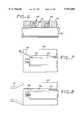
- FIG. 1is a schematic illustration of a device according to the present invention positioned in the heart;
- FIG. 2is a schematic illustration of a preferred method of positioning multiple devices of the present invention in the heart
- FIG. 3is a schematic illustration of an alternative method of positioning multiple devices of the present invention in the heart
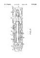
- FIG. 4in a longitudinal cross-section of an embodiment of the present invention
- FIG. 5is an enlarged view of circled section III of FIG. 4;
- FIG. 6is an enlarged view of an alternative embodiment of the seal configuration shown in FIG. 5;
- FIG. 7is a schematic illustration of a drive unit incorporating a visual charge indicator
- FIG. 8is a schematic illustration of a drive unit incorporating a purge system
- FIG. 9is a longitudinal cross-section of a statorless embodiment of the present invention.
- FIG. 10is a longitudinal cross-section of another embodiment of the present invention.
- FIG. 11is a longitudinal cross-section of yet another embodiment of the present invention.
- FIG. 12is a schematic illustration of an alternate embodiment microaxial pump shown deployed within a vessel
- FIG. 13is a schematic illustration of another alternative embodiment microaxial pump shown deployed within a vessel
- FIG. 14is a cross-sectional view of drive unit components assembled within a mold.
- FIG. 15is a schematic illustration of a system for controlling the operation of the microaxial pump.
- the figuresgenerally illustrate various preferred embodiments of the intravascular microaxial pump of the present invention.
- the pump or pumpsare introduced into a patient's vasculature either by surgical implantation therein or by advancement therethrough to a location where fluid is to be pumped.
- the deviceis not limited to the pumping of any particular type of fluid nor for use at any one particular location in the body.
- FIG. 1depicts an exemplary application of the microaxial pump of the present invention wherein the pump is being utilized to pump blood and more particularly, to provide left ventricular support wherein blood is pumped from within the ventricle out into the aorta.
- the microaxial pump 10includes a drive unit 11 and a pumping segment 12, which are arranged coaxially one behind the other to yield a generally cylindrical structure. Distally extending from the pumping segment is an inlet cannula 13, which has openings formed in its distal end as well as its sides to permit entry of fluid into the pump.
- the proximal end of the microaxial pump 10is connected to a catheter 14, which has been inserted via the femoral artery through the aortic arch 15 and into the ventricle 17.
- the microaxial pump 10is positioned primarily in the ascending aorta 9, such that the straight, short inlet cannula 13 protrudes into the heart chamber 17.
- the aortic valve 18is in the closed state either sealed about the outside of the pumping segment or about the inlet cannula.
- the microaxial pump 10 with the front-mounted inlet cannula 13is advanced into the position depicted by manipulation of the catheter 14, that extends proximally therefrom possibly with the aid of a guide wire. Once in position, blood is drawn from the ventricle through the inlet cannula 13, through the pumping segment, and pumped out over the drive unit into the aorta 16.
- FIG. 2illustrates a preferred method of using the pump configuration generally described in FIG. 1, and requires the simultaneous placement of two pumps in the head with the capability of assuming total circulatory support.
- Both pumpsare shown as having been percutaneously placed wherein the catheter 14 of the left pump 141 extends through the vasculature exiting through a peripheral artery while the right side pump catheter 126 extends through the venous vasculature exiting through a peripheral vein.
- the left pump 141is positioned and is operated precisely as described above and shown in FIG. 1.
- the right side pump 122is operated in a reverse flow manner wherein fluid is drawn in over the drive unit 124 into port 143 and out through cannula 121.
- bloodis drawn from either the right atrium 162 or the right ventricle 130 and is discharged into the pulmonary artery 134.
- the right outlet cannula 121is positioned across the pulmonary valve 132 and into the pulmonary artery 134.
- FIG. 3illustrates an alternative method of placing two pumps in the heart with the capability of assuming total circulatory support.
- Both pumpsare shown as having been surgically implanted wherein the catheter 14 of the left pump 141 extends through the aortic wall at 136 while the right side pump catheter 126 extends through the pulmonary artery 134 at 138.
- the left inlet cannula 13is positioned within left ventricle 17 and sealed by the aortic valve 18 distal to the discharge port 140.
- the right inlet cannula 120is positioned within right ventricle 130 and sealed by the pulmonary valve 132.
- Both pumpsare operated so as to draw blood in through cannulas 13, 120 and discharge via port 140, 142.
- FIG. 4depicts a preferred exemplary embodiment of the microaxial pump clearly showing the drive unit 11 and the pumping segment 12 rigidly attached to one another.
- the drive unit 11has an elongated cylindrical housing 20 in which the electric motor 21 is disposed. On the proximal end, the housing 20 is sealed by an end wall 22 to which the flexible catheter 14 is sealingly connected.
- the electrical conduits 23 that supply power and with which the electric motor 21 is controlledextend through the catheter 14.
- the electric motoris an electronically commutated synchronous device wherein the stator 24 consists of small ferritic ring-shaped layers and of interior windings as is well known in the art.
- the stator 24is solidly attached to the interior of motor housing 20, surrounds the rotor 26 and is dimensioned to leave an air gap of about 0.1 mm therebetween.
- the rotorconsisting of permanent magnets magnetized in the circumferential direction, surrounds and is rigidly attached to the shaft 25.
- Such shaftis supported at its proximal end by bearing 27 which is embedded in either the motor housing or in the end wall 22.
- the shaftextends through the entire length of the motor housing 20 and protrudes from its distal end to serve as the drive shaft.
- the distal end of the motor housing 20forms a tube 30 which has the same diameter on its proximal end 30a as the cylindrical housing 20 and is sealingly connected thereto.
- a tapering section 30bextends distally therefrom wherein its external diameter gradually reduces down to that of the cylindrical distal end section 30c. The taper is contoured to promote the smooth flow of pumped fluid thereover.
- Radial ribs 31, whose outer ends support the cylindrical tubular pump housing 32,extend radially outwardly from the end section 30c of the tube 30 and serve as fixed stator elements to direct the flow of fluid discharged from the adjacent impeller 34.
- Shaft 25is supported at the extreme distal end of section 30c by bearing 33 which also serves as a seal.
- the shaft 25extends distally from tube 30 and supports hub 35 on its distal end. Vanes 36 or pump blades extend outwardly from the hub to form the impeller 34.
- the impeller 34is configured such that upon rotation, fluid is drawn in through the front intake opening 37 of the pump housing 32 and driven proximally within the pump housing 32. The fluid flows past the stator blades 31 and outwardly through the annular gap between the pump housing 32 and the motor housing 20 along the section 30b of the tube 30 and over the outer surface of the motor housing 20 thereby serving to remove any heat generated by the drive unit.
- the motor housing 20 and the pump housing 32have roughly the same diameter in the embodiment illustrated, however, the external diameter of the pump housing 32 may be somewhat larger than that of the motor housing, since the pumped fluid must pass through rather than over the housing and any backflow between its external surface and the vessel walls is counterproductive.
- the motor housing and all internal componentsare configured so as to provide only the minimum mechanical clearances necessary for assembly and for uninhibited rotation. Due to the drag imposed by liquids, it is desirable to fill the void space within the drive unit with a gas. Alternatively, if the charge fluid is selected to be a liquid, clearance dimensions are somewhat relaxed to accommodate the liquid. Allowances are made for typical manufacturing tolerances, differential thermal expansion and the effect of expected mechanical stresses. The amount of fluid that could escape into the patient in the event of seal failure is thereby minimized. The risk is further reduced by sealing the drive unit at ambient atmospheric pressure.
- FIG. 5is an enlarged view showing the seal/bearing element seated within recess 38 which is open toward the shaft and toward the distal end.
- the bearing body 39is made of polytetrafluoroethylene TEFLON!, which has a high hardness and a low coefficient of function with the surface of drive shaft 25.
- the sealing bead 40disposed on its inner surface surrounds the rotating shaft 25 along a single line.
- a spring element 41positioned in the interior of the bearing body 39, presses the bead area 40 against the shaft 25 so as to maintain a seal. Combining the sealing and support function in a single component allows the bearing to be positioned as close to the impeller as possible.
- the double seal configuration shown in FIG. 6may be employed wherein the secondary seal 70 improves overall sealing reliability.
- the small void volume 72 disposed between the primary 33 and secondary seal 70is filled with a small amount of biocompatible lubricant that is retained therein to keep initial seal friction very low and improve seal life.
- the primary sealfails, bodily fluids entering the device would be retained within the void space and prevent the motor from being damaged.
- the primary sealwere to fail catastrophically, only a small amount of the biocompatible lubricant would enter the patient while the fluids present within the motor would be contained by the secondary seal.
- the secondary sealis identical to the primary seal. In the event friction levels must be reduced, a secondary seal with a lower sealing force and thus lower friction may be employed.
- the void space within said drive unitis filled during the assembly process with a gas at slightly superatmospheric pressure.
- the gasis selected for its chemical inertness to protect the internal motor components as well as for its biocompatibility and its ability to be quickly absorbed in the pumped fluid in the event the seal leaks or fails.
- the superatmospheric pressurewould result in transfer of benign gas to the pumped fluid and thereby protect the motor from fluid incursion and damage.
- FIG. 7A further feature advantageous for use in drive unit configurations incorporating the superatmospheric gas charge described above is illustrated in FIG. 7.
- the motor housing 20incorporates an internal conduit 74 for setting the void space 76 within the drive unit into fluid communication with a flexible diaphragm 78 disposed on the surface of the housing. Upon pressurization, the diaphragm becomes domed to provide a visual indication as to the state of charge.
- the diaphragmadditionally serves as a reservoir of gas or other charge fluid and thereby extends the shelf life of the device.
- the interior of the drive unitis set into fluid communication with the catheter 14 via duct 78 as is schematically shown in FIG. 8, whereby the void space 76 within the drive unit is continually supplied with a biocompatible purge fluid such as water sterilized from an extracorporeal source (not shown).
- the purge fluidis pressurized so as to maintain a slow purge rate over the seals of about 1-5 ml/hr. This precludes the incursion of bodily fluid into the drive unit and additionally extends the service life of the seals as the purge fluid continually lubricates the rotating seal interface as it is slowly forced thereacross. Because of the high rotational speed of the motor, clearance dimensions are somewhat relaxed to accommodate the presence of the purge fluid and thus reduce drag.
- a purge fluidis selected that is not chemically inert with respect to the components within the drive unit, such components are coated with a thin environmental seal such as paralyene.
- FIG. 9illustrates an alternative embodiment wherein the pumping segment is devoid of a pump stator. While the presence of a stator is useful in optimizing pumping efficiency at a specified design point (flow rate and pressure) and enhancing the maximum pressure head, it has been found that operation of such pump can rarely be held at such design point. This is especially true when the pump is utilized in a supporting role for the heart where a wide range of flow and pressure conditions may be encountered and the pulsatile nature of the heart output continually varies these parameters. Operation of the pump well outside the design point yields a mismatch of flow velocity entrance angles with respect to the entrance angle to a particular stator.
- FIG. 10depicts an exemplary embodiment of the present invention wherein the drive unit 11 is completely sealed so as to substantially alleviate any risk of leakage either from the drive unit into the patient or from the patient into the drive unit.
- a non-rotating, stationary shaft 80extends through the entire drive unit from the end wall 22 through a sealing end wall 45 to protrude from the distal end of the motor housing 20.
- the motor shaft 50 which carries the rotor 26has a central bore 82 formed therein through which the stationary shaft 80 extends.
- the motor shaft 50is supported on its proximal end by bearing 51 which in turn is embedded within the motor housing.
- the distal end of motor shaft 50is supported by bearing 52 which is carried by non-rotating shaft 80.
- the rotorcarries a magnet 54 on its distal end which is rigidly connected thereto and is positioned to spin adjacent to the non-magnetic end wall 45.
- the distal end of the shaft 80protrudes into the pump housing 32 to support the hub 46 of impeller 34. Because the shaft does not rotate, a hermetic seal is readily formed at its interface with end wall 45.
- the hubis rotatably supported on the end of the shaft by a combined axial/radial bearing 47 in the form of a sphere. Both the distal end of the shaft 80 as well as bore 48 have a conical depression formed therein to accommodate the bearing 47.
- the shaft 80is received in an oversized bore so as to provide sufficient radial clearance to allow the hub 46 to pivot slightly about the axial/radial bearing 47.
- the end wall 45is arched toward the interior of the motor housing, whereby the axial/radial bearing 47 forms the center of the arch.
- the arched configurationenables the impeller to pivot about bearing 47 and automatically assume a centered position.
- a flushing bore 48awhich extends through the hub from its distal end to the bore 48, serves to conduct a continuous flow of pumping fluid through the bore 48 to prevent the formation of thrombi.
- the presence of fluid in the boreadditionally serves to dampen any pivoting motion the hub may undergo as it self centers and thereby serves to automatically stabilize the rotating impeller. This allows extremely high rotational speeds to be achieved without impeller-to-housing contact.
- the hub 46and hence impeller, is rotatably coupled to the magnetic rotor within housing 20.
- a magnet 55is rigidly connected to the hub 46 and serves to transfer rotation from the rotor to the impeller.
- the magnetic holding force of the coupling 53is also sufficiently strong to overcome the force which urges the impeller 34 in a distal direction during operation such that the impeller 34 is held by its hub 46 on the shaft 25 exclusively by the magnet holding force.
- the particular embodiment illustratedemploys a statorless design wherein the impeller is extended proximally and engages the hub 46 at a relatively shallow angle. Elimination of the fixed stator additionally reduces the number of connection points to the motor housing, each of which is an area of very low flow velocity and hence a growth site for thrombi formation. Moreover, elimination of the fixed stator reduces the overall parts count and construction complexity and thus serves to reduce total cost.
- the exemplary embodiment shown in FIG. 11is similar to the embodiment illustrated in FIG. 4, however, the impeller 34, along with the shaft 25 and the rotor 26 as well as the tube 30 and the pump housing 32, forms a disposable unit, the boundaries of which are indicated by the broken line 61.
- the bearing 33 and bearing 27also are part of the disposable unit.
- the disposable unit 60is made up of parts which may be manufactured relatively simply and inexpensively. They are removed as a unit from the motor housing 20 and disposed of after use to be replaced by another disposable unit. The remaining components, i.e. the housing, attached stator, and catheter are readily sterilized. As a result, the substantially more expensive components are reusable while the relatively inexpensive components are disposable.
- FIGS. 12 and 13illustrate alternative embodiments of the fluid pump of the present invention that include components for centering the pump within the vasculature and stabilizing its position. Additionally, components are included that prevent backflow in order to boost the efficiency of the pump.
- Attached to the exterior of the drive unit housing 20are at least three centering projections 84 that extend radially toward the vessel wall. Each projection consists of a spring-like rib which is optimally narrowed toward its outer end. The projections serve to center the device within the vessel to ensure that an adequate flowpath is maintained about its entire circumference.
- FIG. 12illustrates an embodiment that includes a flexible sealing element 88.
- the sealgenerally has the shape of a truncated cone and is attached to the pump housing 32 by its smaller distal end. Its larger, proximally extending end is expandable to engage the wall of the vessel 86 and conversely, is collapsible to lie against the pump housing 20.
- the seal 88thus operates like a flap trap.
- the sealing elementexpands to engage the surrounding vessel and seal the annular space between the pump housing and the vessel wall. This prevents backflow of the pumped fluid to boost efficiency. Should the fluid pressure on the distal side of the seal exceed the pressure on the proximal side, the seal collapses so as not to impede flow within the vessel.
- the seal's flexibilityadditionally allows the pump to be maneuvered within the vasculature without unnecessary resistance.
- an expandable annular balloon 90is fitted about the pump housing 32.
- This balloonis in fluid communication with a lumen (not shown) of catheter 14 such that it can be inflated extracorporeally with gas or liquid.
- the balloonexpands to engage the surrounding vessel wall to prevent the backflow of fluid and additionally serves to center the pumping segment 12 and the attached inlet cannula 13 within the vessel.
- the centering projections 84 along with the inflatable balloon 90additionally serve to effectively prevent rotation and axial migration of the entire pump device within the vessel.
- FIG. 14illustrates an efficient technique for manufacturing the drive unit and more specifically, the housing and stator components of such unit.
- the techniqueinvolves a relatively simple injection molding process.
- the interior windings 92 and outer lamination stack 94which form the stator 24, along with conductors 23, are initially assembled about an assembly rod 96.
- the proximal bearing 27is filled with wax to prevent the incursion of polymer, and is also affixed about the rod 96.
- the entire assemblyis placed in and centered within an injection mold 98 afterwhich polymer is injected.
- the polymerpermeates all of the void space to rigidly fix all of the aligned components in place and simultaneously form a casing equivalent to housing 20 such as for example in FIG. 4.
- the moldingis removed from the mold and the assembly rod is removed from the molding.
- a housing/stator combinationis thereby provided ready to receive the rotor and undergo final assembly. Less parts, including less machined parts, are needed, alignment is automatically achieved, the stator becomes integrated in the housing and the conductors are embedded and secured within the polymer. This method is substantially less labor intensive than heretofore employed methods and is readily adaptable to automation.
- the thin polymer motor housingdoes not impair heat transfer and is coated with polyurethane in order to achieve biocompatibility. Different dyes may be incorporated in the polymer in order to conveniently designate different pump sizes.
- FIG. 15is a schematic representation of an alternative embodiment of the present invention wherein pressure sensors are fitted to the flow pump. More specifically, a first pressure sensor is attached to the surface of the drive unit 11 near the pumping segment discharge 140 while a second sensor 104 is fitted near the inlet to the pump housing. Sensor conductors 106 are incorporated in the pump components including for example, within, as for example in FIGS. 6 and 10, support 49 and extend through catheter 14 along with conductors 23, to set the sensors into communication with interface 108.
- a control module 110receives and interprets the signals and controls the power conducted to the drive unit. Information relating to the current actually drawn by the motor is also provided to the control module.
- a keypad and display unit 112is additionally interconnected with the control unit 110 to provide input and monitoring capability.
- a second flow pumpis fitted with sensors and interconnected to the control system to facilitate the coordinated operation of both pumps to optimize pumping performance.
- the first pumpmay for example be placed in the left ventricle while the second pump may be placed in the right ventricle.
- a first pressure sensor 154is attached to the surface of the drive unit 124 near the pumping segment discharge 142 while a second sensor 156 is fitted near the inlet to the pump housing.
- Sensor conductors 150are incorporated in the pump components including for example with support 149 and extend through catheter 126 along with the motor power conductor 150 to set the sensors into communication with the interface 108.
- Additional oxygen sensor 158is fitted and interconnected with interface 108 to provide data reflecting the oxygenation of the blood.
- Information relating to the inlet and outlet pressure along with the power consumption of the electric motorprovides a wealth of information relevant to the function of the pump device.
- such dataenables real time support for the task of pump placement potentially without the additional equipment needed for fluoroscopic techniques.
- real time avoidance of conditions indicating the incipient onset of cavitationis possible while real time indications of flow blockage due to a blocked or collapsed inlet conduit or the formation of thrombi in the inlet, on the pump housing, or impeller signal the need for remedial action to be taken.
- the sensorsalso provide the capability of monitoring motor or pump wear or failure as well as the prediction of such events.
- operation of the pumpcan be maintained with acceptable total hemolysis rates over the anticipated use period and output rate while pulsatile and non-pulsatile flow can be controlled.
- the performance trends of various parameters over many hours of operationcan be displayed and analyzed while alarm features indicating conditions that need immediate attention facilitate operation with reduced supervision.
- the patient's heartcan be monitored without removal of the pump.
- control modulemay gain local information supplied by one pump to modify the operation of the second pump thereby facilitating optimization of the net output of the system as a whole.
Landscapes
- Health & Medical Sciences (AREA)
- Engineering & Computer Science (AREA)
- Heart & Thoracic Surgery (AREA)
- Mechanical Engineering (AREA)
- Cardiology (AREA)
- Animal Behavior & Ethology (AREA)
- Biomedical Technology (AREA)
- Hematology (AREA)
- Life Sciences & Earth Sciences (AREA)
- Anesthesiology (AREA)
- General Health & Medical Sciences (AREA)
- Public Health (AREA)
- Veterinary Medicine (AREA)
- Power Engineering (AREA)
- General Engineering & Computer Science (AREA)
- Physics & Mathematics (AREA)
- Vascular Medicine (AREA)
- Fluid Mechanics (AREA)
- Medical Informatics (AREA)
- Human Computer Interaction (AREA)
- Electromagnetism (AREA)
- Manufacturing & Machinery (AREA)
- External Artificial Organs (AREA)
Abstract
Description
Claims (49)
Priority Applications (29)
| Application Number | Priority Date | Filing Date | Title |
|---|---|---|---|
| US08/832,040US5911685A (en) | 1996-04-03 | 1997-04-02 | Method and apparatus for cardiac blood flow assistance |
| US08/881,884US5964694A (en) | 1997-04-02 | 1997-06-24 | Method and apparatus for cardiac blood flow assistance |
| US08/881,885US5921913A (en) | 1996-04-03 | 1997-06-24 | Statorless intravascular microaxial flow pump |
| AU72132/98AAU7213298A (en) | 1997-04-02 | 1998-03-31 | Method for producing a micromotor |
| PCT/EP1998/001867WO1998044619A1 (en) | 1997-04-02 | 1998-03-31 | Method for producing a micromotor |
| JP54115698AJP4179634B2 (en) | 1997-04-02 | 1998-03-31 | Intracardiac blood pump |
| AT98921408TATE255430T1 (en) | 1997-04-02 | 1998-03-31 | INTRACARDIAL PUMPING DEVICE |
| PCT/EP1998/001866WO1998043688A1 (en) | 1997-04-02 | 1998-03-31 | Intracardiac blood pump |
| DE59810906TDE59810906D1 (en) | 1997-04-02 | 1998-03-31 | INTRAKARDIAL BLOOD PUMP |
| CN98800423ACN1222863A (en) | 1997-04-02 | 1998-03-31 | Intracardiac blood pump |
| CA002256423ACA2256423A1 (en) | 1997-04-02 | 1998-03-31 | Method for producing a micromotor |
| AT98919196TATE400917T1 (en) | 1997-04-02 | 1998-03-31 | METHOD FOR PRODUCING A MICROMOTOR |
| JP54115898AJP4179635B2 (en) | 1997-04-02 | 1998-03-31 | Intracardiac pump device |
| DE59810330TDE59810330D1 (en) | 1997-04-02 | 1998-03-31 | INTRA-CARDIAL PUMPING DEVICE |
| BR9804804ABR9804804A (en) | 1997-04-02 | 1998-03-31 | An intracardiac blood pump |
| BR9804832ABR9804832A (en) | 1997-04-02 | 1998-03-31 | Intracardiac pumping device |
| JP54115798AJP3982840B2 (en) | 1997-04-02 | 1998-03-31 | Manufacturing method of micro motor |
| US09/194,725US6139487A (en) | 1997-04-02 | 1998-03-31 | Intracardiac pump device |
| EP98919196AEP0904630B1 (en) | 1997-04-02 | 1998-03-31 | Method for producing a micromotor |
| EP98921407AEP0925080B1 (en) | 1997-04-02 | 1998-03-31 | Intracardiac blood pump |
| AU74279/98AAU7427998A (en) | 1997-04-02 | 1998-03-31 | Intracardiac blood pump |
| IL12724898AIL127248A0 (en) | 1997-04-02 | 1998-03-31 | A method for producing a micromotor |
| CA002256427ACA2256427A1 (en) | 1997-04-02 | 1998-03-31 | Intracardiac blood pump |
| DE59814250TDE59814250D1 (en) | 1997-04-02 | 1998-03-31 | METHOD FOR PRODUCING A MICROMOTOR |
| CA002256432ACA2256432A1 (en) | 1997-04-02 | 1998-03-31 | Intracardiac pump device |
| PCT/EP1998/001868WO1998043689A1 (en) | 1997-04-02 | 1998-03-31 | Intracardiac pump device |
| US09/194,644US6058593A (en) | 1997-04-02 | 1998-03-31 | Method for producing a micro motor |
| EP98921408AEP0925081B1 (en) | 1997-04-02 | 1998-03-31 | Intracardiac pump device |
| AU74280/98AAU7428098A (en) | 1997-04-02 | 1998-03-31 | Intracardiac pump device |
Applications Claiming Priority (5)
| Application Number | Priority Date | Filing Date | Title |
|---|---|---|---|
| DE19613564 | 1996-04-03 | ||
| DE19613565 | 1996-04-03 | ||
| DE19613565ADE19613565C1 (en) | 1996-04-04 | 1996-04-04 | Intravasal blood pump with drive motor |
| DE19613564ADE19613564C1 (en) | 1996-04-04 | 1996-04-04 | Intravascular blood pump |
| US08/832,040US5911685A (en) | 1996-04-03 | 1997-04-02 | Method and apparatus for cardiac blood flow assistance |
Related Child Applications (3)
| Application Number | Title | Priority Date | Filing Date |
|---|---|---|---|
| US08/881,885DivisionUS5921913A (en) | 1996-04-03 | 1997-06-24 | Statorless intravascular microaxial flow pump |
| US08/881,884DivisionUS5964694A (en) | 1997-04-02 | 1997-06-24 | Method and apparatus for cardiac blood flow assistance |
| US09/194,725Continuation-In-PartUS6139487A (en) | 1997-04-02 | 1998-03-31 | Intracardiac pump device |
Publications (1)
| Publication Number | Publication Date |
|---|---|
| US5911685Atrue US5911685A (en) | 1999-06-15 |
Family
ID=27216116
Family Applications (2)
| Application Number | Title | Priority Date | Filing Date |
|---|---|---|---|
| US08/832,040Expired - LifetimeUS5911685A (en) | 1996-04-03 | 1997-04-02 | Method and apparatus for cardiac blood flow assistance |
| US08/881,885Expired - LifetimeUS5921913A (en) | 1996-04-03 | 1997-06-24 | Statorless intravascular microaxial flow pump |
Family Applications After (1)
| Application Number | Title | Priority Date | Filing Date |
|---|---|---|---|
| US08/881,885Expired - LifetimeUS5921913A (en) | 1996-04-03 | 1997-06-24 | Statorless intravascular microaxial flow pump |
Country Status (1)
| Country | Link |
|---|---|
| US (2) | US5911685A (en) |
Cited By (173)
| Publication number | Priority date | Publication date | Assignee | Title |
|---|---|---|---|---|
| US6007478A (en)* | 1997-11-13 | 1999-12-28 | Impella Cardiotechnik Aktiengesellschaft | Cannula having constant wall thickness with increasing distal flexibility and method of making |
| WO2000019184A1 (en)* | 1998-09-29 | 2000-04-06 | Remon Medical Technologies Ltd. | System and method for monitoring pressure, flow and constriction parameters of plumbing and blood vessels |
| US6058593A (en)* | 1997-04-02 | 2000-05-09 | Impella Cardiotechnick Gmbh | Method for producing a micro motor |
| US6129704A (en)* | 1997-06-12 | 2000-10-10 | Schneider (Usa) Inc. | Perfusion balloon catheter having a magnetically driven impeller |
| US6135729A (en)* | 1993-11-10 | 2000-10-24 | The United States Of America As Represented By The Administrator Of The National Aeronautics And Space Administration | Blood pump bearing system |
| US6176848B1 (en) | 1996-04-04 | 2001-01-23 | Impella Cardiotechnik Gmbh | Intravascular blood pump |
| US6176822B1 (en) | 1998-03-31 | 2001-01-23 | Impella Cardiotechnik Gmbh | Intracardiac blood pump |
| US6217541B1 (en) | 1999-01-19 | 2001-04-17 | Kriton Medical, Inc. | Blood pump using cross-flow principles |
| WO2002041935A1 (en)* | 2000-11-25 | 2002-05-30 | Impella Cardiosystems Ag | Miniature motor |
| US6440059B1 (en) | 1999-10-14 | 2002-08-27 | Cimex Biotech Lc | Magnetohydrodynamic cardiac assist device |
| US6471979B2 (en) | 1999-12-29 | 2002-10-29 | Estrogen Vascular Technology, Llc | Apparatus and method for delivering compounds to a living organism |
| US6506025B1 (en)* | 1999-06-23 | 2003-01-14 | California Institute Of Technology | Bladeless pump |
| US6592612B1 (en) | 2000-05-04 | 2003-07-15 | Cardeon Corporation | Method and apparatus for providing heat exchange within a catheter body |
| US6610004B2 (en) | 1997-10-09 | 2003-08-26 | Orqis Medical Corporation | Implantable heart assist system and method of applying same |
| AU769794B2 (en)* | 1999-02-06 | 2004-02-05 | Impella Cardiotechnik Ag | Device for intravascular cardiac valve surgery |
| US20040056537A1 (en)* | 2001-01-09 | 2004-03-25 | Du Hung T. | Dynamoelectric machine having encapsulated coil structure with one or more of phase change additives, insert molded features and insulated pinion |
| US6719791B1 (en)* | 1999-04-20 | 2004-04-13 | Berlin Heart Ag | Device for the axial transport of fluid media |
| US6735846B2 (en) | 2001-01-09 | 2004-05-18 | Black & Decker Inc. | Method for forming an electric motor having armature coated with a thermally conductive plastic |
| US20040116768A1 (en)* | 1997-10-09 | 2004-06-17 | Bolling Steven F. | Implantable heart assist system and method of applying same |
| US6858001B1 (en)* | 1997-07-11 | 2005-02-22 | A-Med Systems, Inc. | Single port cardiac support apparatus |
| US20050085683A1 (en)* | 2003-10-15 | 2005-04-21 | Bolling Steven F. | Implantable heart assist system and method of applying same |
| US20050107657A1 (en)* | 2002-03-08 | 2005-05-19 | Michel Carrier | Dual inlet mixed-flow blood pump |
| US20050131385A1 (en)* | 2003-12-12 | 2005-06-16 | Bolling Steven F. | Cannulae for selectively enhancing blood flow |
| US20050148811A1 (en)* | 1997-07-11 | 2005-07-07 | A-Med Systems, Inc. | Single port cardiac support apparatus |
| US20050234288A1 (en)* | 1998-05-15 | 2005-10-20 | A-Med Systems, Inc. | Pulmonary and circulatory blood flow support devices and methods for heart surgery procedures |
| US7011620B1 (en)* | 1999-12-04 | 2006-03-14 | Impella Cardiosystems Ag | Intravascular blood pump |
| US7013552B2 (en) | 2001-01-09 | 2006-03-21 | Black & Decker Inc. | Method for forming an armature for an electric motor for a portable power tool |
| US20060122456A1 (en)* | 2004-12-03 | 2006-06-08 | Larose Jeffrey A | Wide blade, axial flow pump |
| US20060161095A1 (en)* | 1999-09-03 | 2006-07-20 | A-Med Systems, Inc. | Guidable intravascular blood pump and related methods |
| US7096566B2 (en) | 2001-01-09 | 2006-08-29 | Black & Decker Inc. | Method for making an encapsulated coil structure |
| US20060245959A1 (en)* | 2005-04-29 | 2006-11-02 | Larose Jeffrey A | Multiple rotor, wide blade, axial flow pump |
| US20070078293A1 (en)* | 2005-10-05 | 2007-04-05 | Shambaugh Charles R Jr | Impeller for a rotary ventricular assist device |
| US7241257B1 (en)* | 2002-06-28 | 2007-07-10 | Abbott Cardiovascular Systems, Inc. | Devices and methods to perform minimally invasive surgeries |
| US20080114339A1 (en)* | 2006-03-23 | 2008-05-15 | The Penn State Research Foundation | Heart assist device with expandable impeller pump |
| US7445592B2 (en) | 2004-06-10 | 2008-11-04 | Orqis Medical Corporation | Cannulae having reduced flow resistance |
| US20090060743A1 (en)* | 2004-09-17 | 2009-03-05 | The Penn State Research Foundation | Expandable impeller pump |
| US20090137480A1 (en)* | 2002-10-31 | 2009-05-28 | Meir Stern | Transdermal delivery system for dried particulate or lyophilized medications |
| US20090203957A1 (en)* | 2008-02-08 | 2009-08-13 | Larose Jeffrey A | Ventricular assist device for intraventricular placement |
| US7621905B2 (en) | 1997-12-30 | 2009-11-24 | Remon Medical Technologies Ltd. | Devices for intrabody delivery of molecules and systems and methods utilizing same |
| US7641619B2 (en) | 2000-10-16 | 2010-01-05 | Remon Medical Technologies, Ltd. | Barometric pressure correction based on remote sources of information |
| US20100125211A1 (en)* | 2008-11-19 | 2010-05-20 | Stahmann Jeffrey E | Assessment of pulmonary vascular resistance via pulmonary artery pressure |
| US7742815B2 (en) | 2005-09-09 | 2010-06-22 | Cardiac Pacemakers, Inc. | Using implanted sensors for feedback control of implanted medical devices |
| US20100174131A1 (en)* | 2007-06-14 | 2010-07-08 | Calon Cardio Technology Limited | Reduced Diameter Axial Rotary Pump for Cardiac Assist |
| US7813808B1 (en) | 2004-11-24 | 2010-10-12 | Remon Medical Technologies Ltd | Implanted sensor system with optimized operational and sensing parameters |
| US7814641B2 (en) | 2001-01-09 | 2010-10-19 | Black & Decker Inc. | Method of forming a power tool |
| US7914436B1 (en) | 2006-06-12 | 2011-03-29 | Abiomed, Inc. | Method and apparatus for pumping blood |
| US7955268B2 (en) | 2006-07-21 | 2011-06-07 | Cardiac Pacemakers, Inc. | Multiple sensor deployment |
| US8118724B2 (en) | 2003-09-18 | 2012-02-21 | Thoratec Corporation | Rotary blood pump |
| US8271093B2 (en) | 2004-09-17 | 2012-09-18 | Cardiac Pacemakers, Inc. | Systems and methods for deriving relative physiologic measurements using a backend computing system |
| US20120234411A1 (en)* | 2009-09-22 | 2012-09-20 | Mario Scheckel | Functional element, in particular fluid pump, having a housing and a conveying element |
| US20120308406A1 (en)* | 2009-12-23 | 2012-12-06 | Ecp Entwicklungsgesellschaft Mbh | Pump device having a detection device |
| US8369960B2 (en) | 2008-02-12 | 2013-02-05 | Cardiac Pacemakers, Inc. | Systems and methods for controlling wireless signal transfers between ultrasound-enabled medical devices |
| US20130053622A1 (en)* | 2009-09-09 | 2013-02-28 | Abiomed, Inc | Method for simultaneously delivering fluid to a dual lumen catheter with a single fluid source |
| US20130066421A1 (en)* | 2011-05-13 | 2013-03-14 | Martin Strueber | Intravascular blood pump and method of implantation |
| US8449443B2 (en) | 2008-10-06 | 2013-05-28 | Indiana University Research And Technology Corporation | Active or passive assistance in the circulatory system |
| US8485961B2 (en) | 2011-01-05 | 2013-07-16 | Thoratec Corporation | Impeller housing for percutaneous heart pump |
| WO2013119752A2 (en) | 2012-02-07 | 2013-08-15 | Hridaya, Inc. | Hemodynamic assist device |
| US8535211B2 (en) | 2009-07-01 | 2013-09-17 | Thoratec Corporation | Blood pump with expandable cannula |
| WO2013160407A1 (en) | 2012-04-27 | 2013-10-31 | Abiomed Europe Gmbh | Intravascular rotary blood pump |
| US8591393B2 (en) | 2011-01-06 | 2013-11-26 | Thoratec Corporation | Catheter pump |
| US8591423B2 (en) | 2008-10-10 | 2013-11-26 | Cardiac Pacemakers, Inc. | Systems and methods for determining cardiac output using pulmonary artery pressure measurements |
| US8597170B2 (en) | 2011-01-05 | 2013-12-03 | Thoratec Corporation | Catheter pump |
| US8721517B2 (en) | 2012-05-14 | 2014-05-13 | Thoratec Corporation | Impeller for catheter pump |
| US8725260B2 (en) | 2008-02-11 | 2014-05-13 | Cardiac Pacemakers, Inc | Methods of monitoring hemodynamic status for rhythm discrimination within the heart |
| US8821365B2 (en) | 2009-07-29 | 2014-09-02 | Thoratec Corporation | Rotation drive device and centrifugal pump apparatus using the same |
| US20150051436A1 (en)* | 2012-02-16 | 2015-02-19 | Abiomed Europe Gmbh | Intravascular blood pump |
| US9067005B2 (en) | 2008-12-08 | 2015-06-30 | Thoratec Corporation | Centrifugal pump apparatus |
| US9138518B2 (en) | 2011-01-06 | 2015-09-22 | Thoratec Corporation | Percutaneous heart pump |
| US20150335803A1 (en)* | 2013-01-07 | 2015-11-26 | National University Corporation Kobe University | Axial flow blood pump |
| US9308302B2 (en) | 2013-03-15 | 2016-04-12 | Thoratec Corporation | Catheter pump assembly including a stator |
| US9327067B2 (en) | 2012-05-14 | 2016-05-03 | Thoratec Corporation | Impeller for catheter pump |
| US9328741B2 (en) | 2010-05-17 | 2016-05-03 | Ecp Entwicklungsgesellschaft Mbh | Pump arrangement |
| US9358329B2 (en) | 2012-07-03 | 2016-06-07 | Thoratec Corporation | Catheter pump |
| US9381288B2 (en) | 2013-03-13 | 2016-07-05 | Thoratec Corporation | Fluid handling system |
| US20160220125A1 (en)* | 2015-01-30 | 2016-08-04 | Infineon Technologies Ag | Implantable Vessel Fluid Sensor |
| US9421311B2 (en) | 2012-07-03 | 2016-08-23 | Thoratec Corporation | Motor assembly for catheter pump |
| US9446179B2 (en) | 2012-05-14 | 2016-09-20 | Thoratec Corporation | Distal bearing support |
| US9474840B2 (en) | 2012-04-27 | 2016-10-25 | Abiomed Europe Gmbh | Intravascular rotary blood pump |
| US9512852B2 (en) | 2006-03-31 | 2016-12-06 | Thoratec Corporation | Rotary blood pump |
| US20170012493A1 (en)* | 2014-03-31 | 2017-01-12 | Namiki Seimitsu Houseki Kabushiki Kaisha | Micro motor, micro-geared motor with micro motor, and method for manufacturing micro motor |
| US9556873B2 (en) | 2013-02-27 | 2017-01-31 | Tc1 Llc | Startup sequence for centrifugal pump with levitated impeller |
| US9572915B2 (en) | 2012-03-26 | 2017-02-21 | Procyrion, Inc. | Systems and methods for fluid flows and/or pressures for circulation and perfusion enhancement |
| US9623161B2 (en) | 2014-08-26 | 2017-04-18 | Tc1 Llc | Blood pump and method of suction detection |
| US9638202B2 (en) | 2010-09-14 | 2017-05-02 | Tc1 Llc | Centrifugal pump apparatus |
| US9675739B2 (en) | 2015-01-22 | 2017-06-13 | Tc1 Llc | Motor assembly with heat exchanger for catheter pump |
| US9675738B2 (en) | 2015-01-22 | 2017-06-13 | Tc1 Llc | Attachment mechanisms for motor of catheter pump |
| US9709061B2 (en) | 2013-01-24 | 2017-07-18 | Tc1 Llc | Impeller position compensation using field oriented control |
| US9770543B2 (en) | 2015-01-22 | 2017-09-26 | Tc1 Llc | Reduced rotational mass motor assembly for catheter pump |
| US9775936B2 (en) | 2010-10-18 | 2017-10-03 | WorldHeart Corp. | Blood pump with separate mixed-flow and axial-flow impeller stages, components therefor and related methods |
| US9827356B2 (en) | 2014-04-15 | 2017-11-28 | Tc1 Llc | Catheter pump with access ports |
| US9850906B2 (en) | 2011-03-28 | 2017-12-26 | Tc1 Llc | Rotation drive device and centrifugal pump apparatus employing same |
| US9872947B2 (en) | 2012-05-14 | 2018-01-23 | Tc1 Llc | Sheath system for catheter pump |
| EP3287155A1 (en) | 2016-08-23 | 2018-02-28 | Abiomed Europe GmbH | Blood pump |
| US9907890B2 (en) | 2015-04-16 | 2018-03-06 | Tc1 Llc | Catheter pump with positioning brace |
| EP3311859A1 (en) | 2016-10-19 | 2018-04-25 | Abiomed Europe GmbH | Ventricular assist device control |
| US10029037B2 (en) | 2014-04-15 | 2018-07-24 | Tc1 Llc | Sensors for catheter pumps |
| EP3357523A1 (en) | 2017-02-07 | 2018-08-08 | Abiomed Europe GmbH | Blood pump |
| US10052420B2 (en) | 2013-04-30 | 2018-08-21 | Tc1 Llc | Heart beat identification and pump speed synchronization |
| WO2018175563A1 (en)* | 2017-03-21 | 2018-09-27 | Abiomed, Inc. | System and method for determining native cardiac output while continuing support to the heart with a catheter-mounted intracardiac blood pump having an imbedded thermistor |
| US10105475B2 (en) | 2014-04-15 | 2018-10-23 | Tc1 Llc | Catheter pump introducer systems and methods |
| US10111994B2 (en) | 2013-05-14 | 2018-10-30 | Heartware, Inc. | Blood pump with separate mixed-flow and axial-flow impeller stages and multi-stage stators |
| US10117983B2 (en) | 2015-11-16 | 2018-11-06 | Tc1 Llc | Pressure/flow characteristic modification of a centrifugal pump in a ventricular assist device |
| US10166318B2 (en) | 2015-02-12 | 2019-01-01 | Tc1 Llc | System and method for controlling the position of a levitated rotor |
| US10183143B2 (en) | 2013-03-15 | 2019-01-22 | Bitol Designs, Llc | Occlusion resistant catheter and method of use |
| US10245361B2 (en) | 2015-02-13 | 2019-04-02 | Tc1 Llc | Impeller suspension mechanism for heart pump |
| US20190201603A1 (en)* | 2015-06-23 | 2019-07-04 | Abiomed Europe Gmbh | Blood pump |
| US10342906B2 (en) | 2016-06-06 | 2019-07-09 | Abiomed, Inc. | Blood pump assembly having a sensor and a sensor shield |
| US10371152B2 (en) | 2015-02-12 | 2019-08-06 | Tc1 Llc | Alternating pump gaps |
| US10449279B2 (en) | 2014-08-18 | 2019-10-22 | Tc1 Llc | Guide features for percutaneous catheter pump |
| US10506935B2 (en) | 2015-02-11 | 2019-12-17 | Tc1 Llc | Heart beat identification and pump speed synchronization |
| WO2020003110A2 (en) | 2018-06-25 | 2020-01-02 | Modeus Inc. | Percutaneous blood pump and introducer system |
| US10525178B2 (en) | 2013-03-15 | 2020-01-07 | Tc1 Llc | Catheter pump assembly including a stator |
| US10583232B2 (en) | 2014-04-15 | 2020-03-10 | Tc1 Llc | Catheter pump with off-set motor position |
| CN111902168A (en)* | 2018-03-23 | 2020-11-06 | 阿比奥梅德欧洲股份有限公司 | intravascular blood pump |
| US10881770B2 (en) | 2018-01-10 | 2021-01-05 | Magenta Medical Ltd. | Impeller for blood pump |
| US11033728B2 (en) | 2013-03-13 | 2021-06-15 | Tc1 Llc | Fluid handling system |
| WO2021142490A1 (en) | 2020-01-10 | 2021-07-15 | Abiomed, Inc. | Blood pump with improved leakage control |
| CN113164736A (en)* | 2018-11-29 | 2021-07-23 | 心脏器械股份有限公司 | Thrombectomy manifold for ventricular assist device |
| US11077294B2 (en) | 2013-03-13 | 2021-08-03 | Tc1 Llc | Sheath assembly for catheter pump |
| US20210236803A1 (en)* | 2020-01-31 | 2021-08-05 | Kardion Gmbh | Pump for delivering a fluid and method of manufacturing a pump |
| CN113476738A (en)* | 2021-06-07 | 2021-10-08 | 浙江迪远医疗器械有限公司 | Blood pump with detection device |
| US11160970B2 (en) | 2016-07-21 | 2021-11-02 | Tc1 Llc | Fluid seals for catheter pump motor assembly |
| US20210339005A1 (en)* | 2018-07-20 | 2021-11-04 | Kardion Gmbh | Feed line for a pump unit of a cardiac assistance system, cardiac assistance system and method for producing a feed line for a pump unit of a cardiac assistance system |
| US11191944B2 (en) | 2019-01-24 | 2021-12-07 | Magenta Medical Ltd. | Distal tip element for a ventricular assist device |
| US11219756B2 (en) | 2012-07-03 | 2022-01-11 | Tc1 Llc | Motor assembly for catheter pump |
| US11229786B2 (en) | 2012-05-14 | 2022-01-25 | Tc1 Llc | Impeller for catheter pump |
| US11235138B2 (en) | 2015-09-25 | 2022-02-01 | Procyrion, Inc. | Non-occluding intravascular blood pump providing reduced hemolysis |
| US20220032036A1 (en)* | 2018-08-08 | 2022-02-03 | Kardion Gmbh | Device and method for monitoring the state of health of a patient |
| US11241569B2 (en) | 2004-08-13 | 2022-02-08 | Procyrion, Inc. | Method and apparatus for long-term assisting a left ventricle to pump blood |
| US11260212B2 (en) | 2016-10-25 | 2022-03-01 | Magenta Medical Ltd. | Ventricular assist device |
| US11291826B2 (en) | 2018-01-10 | 2022-04-05 | Magenta Medical Ltd. | Axially-elongatable frame and impeller |
| CN114306921A (en)* | 2020-09-28 | 2022-04-12 | 苏州恒瑞宏远医疗科技有限公司 | Sealing mechanism and heart blood pump |
| US11324940B2 (en) | 2019-12-03 | 2022-05-10 | Procyrion, Inc. | Blood pumps |
| US11351359B2 (en) | 2019-12-13 | 2022-06-07 | Procyrion, Inc. | Support structures for intravascular blood pumps |
| US11368081B2 (en) | 2018-01-24 | 2022-06-21 | Kardion Gmbh | Magnetic coupling element with a magnetic bearing function |
| US11389638B2 (en)* | 2012-02-07 | 2022-07-19 | Hridaya, Inc. | Hemodynamic assist device |
| US11406812B2 (en) | 2016-03-21 | 2022-08-09 | Ramtin Agah | Methods and systems for deployment, charging and retrieval of intracardiac pumps |
| CN114870242A (en)* | 2022-02-23 | 2022-08-09 | 深圳核心医疗科技有限公司 | Blood pump and its driving device |
| CN115066269A (en)* | 2020-02-06 | 2022-09-16 | 阿比奥梅德欧洲股份有限公司 | Blood pump placement and intravascular blood pump |
| CN115154890A (en)* | 2022-06-24 | 2022-10-11 | 上海心恒睿医疗科技有限公司 | Percutaneous ventricular assist system |
| US11484698B2 (en)* | 2019-07-09 | 2022-11-01 | Boston Scientific Scimed, Inc. | Circulatory support device |
| US11491322B2 (en) | 2016-07-21 | 2022-11-08 | Tc1 Llc | Gas-filled chamber for catheter pump motor assembly |
| US11491320B2 (en)* | 2003-08-08 | 2022-11-08 | Abiomed Europe Gmbh | Intracardiac pumping device |
| CN115445078A (en)* | 2022-08-28 | 2022-12-09 | 上海炫脉医疗科技有限公司 | Miniature blood pump and manufacturing method thereof |
| WO2023037162A1 (en) | 2021-09-10 | 2023-03-16 | Abiomed Europe Gmbh | System and method for ventricular assistance support during extracorporeal membrane oxygenation |
| US11632015B2 (en)* | 2018-08-28 | 2023-04-18 | Boston Scientific Scimed, Inc. | Axial flux motor for percutaneous circulatory support device |
| US11754075B2 (en) | 2018-07-10 | 2023-09-12 | Kardion Gmbh | Impeller for an implantable, vascular support system |
| WO2023172567A1 (en)* | 2022-03-08 | 2023-09-14 | Boston Scientific Scimed Inc. | Percutaneous circulatory support device with cannula and expandable element |
| US20230347113A1 (en)* | 2019-02-26 | 2023-11-02 | White Swell Medical Ltd | Devices and methods for treating edema |
| US12005248B2 (en) | 2018-05-16 | 2024-06-11 | Kardion Gmbh | Rotor bearing system |
| US12064614B2 (en) | 2016-03-21 | 2024-08-20 | Ramtin Agah | Methods and systems for deployment, charging and retrieval of intracardiac pumps |
| US12064615B2 (en) | 2018-05-30 | 2024-08-20 | Kardion Gmbh | Axial-flow pump for a ventricular assist device and method for producing an axial-flow pump for a ventricular assist device |
| US12076546B2 (en)* | 2018-01-08 | 2024-09-03 | Star Bp, Inc. | Heart assist device |
| US12107474B2 (en) | 2018-05-16 | 2024-10-01 | Kardion Gmbh | End-face rotating joint for transmitting torques |
| US12128227B2 (en) | 2020-04-07 | 2024-10-29 | Magenta Medical Ltd. | Manufacture of an impeller |
| US12144976B2 (en) | 2018-06-21 | 2024-11-19 | Kardion Gmbh | Method and device for detecting a wear condition of a ventricular assist device and for operating same, and ventricular assist device |
| US12178554B2 (en) | 2018-06-06 | 2024-12-31 | Kardion Gmbh | Systems and methods for determining a viscosity of a fluid |
| US12194287B2 (en) | 2018-05-30 | 2025-01-14 | Kardion Gmbh | Method of manufacturing electrical conductor tracks in a region of an intravascular blood pump |
| US12201821B2 (en) | 2018-06-06 | 2025-01-21 | Kardion Gmbh | Method for determining a flow rate of a fluid flowing through an implanted vascular support system, and implantable vascular support system |
| US12201823B2 (en) | 2018-05-30 | 2025-01-21 | Kardion Gmbh | Line device for conducting a blood flow for a heart support system, heart support system, and method for producing a line device |
| US12222267B2 (en) | 2018-06-06 | 2025-02-11 | Kardion Gmbh | Analysis device and method for analyzing a viscosity of a fluid |
| US12257424B2 (en) | 2018-06-06 | 2025-03-25 | Kardion Gmbh | Implantable ventricular assist system and method for operating same |
| US12263333B2 (en) | 2018-06-21 | 2025-04-01 | Kardion Gmbh | Stator vane device for guiding the flow of a fluid flowing out of an outlet opening of a ventricular assist device, ventricular assist device with stator vane device, method for operating a stator vane device and manufacturing method |
| WO2025092027A1 (en)* | 2023-11-01 | 2025-05-08 | 为泰医疗器械(深圳)有限公司 | Valve balloon suction catheter |
| US12310708B2 (en) | 2018-06-06 | 2025-05-27 | Kardion Gmbh | Systems and methods for determining a flow speed of a fluid flowing through a cardiac assist device |
| US12311160B2 (en) | 2018-06-06 | 2025-05-27 | Kardion Gmbh | Method and system for determining the speed of sound in a fluid in the region of a cardiac support system |
| US12324906B2 (en) | 2018-06-06 | 2025-06-10 | Kardion Gmbh | Systems and methods for determining a total blood volume flow in a cardiac support system and vascular support system |
| CN120168853A (en)* | 2025-05-21 | 2025-06-20 | 乐普心泰(北京)医疗科技有限公司 | Blood pump manufacturing method |
| US12337163B2 (en) | 2018-12-19 | 2025-06-24 | Boston Scientific Scimed, Inc. | Circulatory support device |
| US12377256B2 (en) | 2018-06-06 | 2025-08-05 | Kardion Gmbh | Cardiac support system flow measurement using pressure sensors |
| US12383727B2 (en) | 2018-05-30 | 2025-08-12 | Kardion Gmbh | Motor housing module for a heart support system, and heart support system and method for mounting a heart support system |
| US12390633B2 (en) | 2018-08-07 | 2025-08-19 | Kardion Gmbh | Bearing device for a heart support system, and method for rinsing a space in a bearing device for a heart support system |
| US12440663B2 (en) | 2022-04-18 | 2025-10-14 | Magenta Medical Ltd. | Curved tube for a ventricular assist device |
Families Citing this family (36)
| Publication number | Priority date | Publication date | Assignee | Title |
|---|---|---|---|---|
| US6086527A (en)* | 1998-04-02 | 2000-07-11 | Scimed Life Systems, Inc. | System for treating congestive heart failure |
| US20020128587A1 (en)* | 1999-01-13 | 2002-09-12 | A-Med Systems, Inc. | Pulmonary and circulatory blood flow support devices and methods for heart surgery procedures |
| DE10016422B4 (en)* | 2000-04-01 | 2013-10-31 | Impella Cardiosystems Ag | Paracardiac blood pump |
| US7366754B2 (en)* | 2001-06-29 | 2008-04-29 | Thomson Licensing | Multi-media jitter removal in an asynchronous digital home network |
| CA2439645C (en)* | 2003-09-04 | 2014-03-18 | Hygiene-Technik Inc. | Automated biological growth and dispensing system |
| US8206973B2 (en)* | 2003-09-04 | 2012-06-26 | Gotohti.Com Inc | Automated biological growth and dispensing system |
| AT504990B1 (en) | 2007-02-27 | 2008-12-15 | Miracor Medizintechnik Handels | CATHETER FOR SUPPORTING THE PERFORMANCE OF A HEART |
| WO2009091965A1 (en)* | 2008-01-18 | 2009-07-23 | Med Institute, Inc. | Intravascular device attachment system having tubular expandable body |
| US9636441B2 (en) | 2012-11-05 | 2017-05-02 | Robert Jarvik | Support stent for transvalvular conduit |
| ES2532774B1 (en)* | 2013-09-30 | 2016-01-08 | Fundación Para La Investigación Biomédica Del Hospital Gregorio Marañón | Ventricular assist device |
| GB2527075A (en)* | 2014-03-17 | 2015-12-16 | Daassist As | Percutaneous system, devices and methods |
| US9901722B2 (en) | 2014-06-01 | 2018-02-27 | White Swell Medical Ltd | System and method for treatment of pulmonary edema |
| IL255599B (en) | 2015-05-11 | 2022-08-01 | White Swell Medical Ltd | System and method for reducing outlet pressure from a canal |
| EP3153191A1 (en) | 2015-10-09 | 2017-04-12 | ECP Entwicklungsgesellschaft mbH | Blood pump |
| US10893847B2 (en) | 2015-12-30 | 2021-01-19 | Nuheart As | Transcatheter insertion system |
| EP3506960B1 (en) | 2016-09-01 | 2025-04-23 | Abiomed, Inc. | Anti-suction blood pump inlet |
| US10537672B2 (en) | 2016-10-07 | 2020-01-21 | Nuheart As | Transcatheter device and system for the delivery of intracorporeal devices |
| US10335528B2 (en) | 2016-10-07 | 2019-07-02 | Nuheart As | Transcatheter method and system for the delivery of intracorporeal devices |
| IL266273B (en) | 2016-11-01 | 2022-09-01 | White Swell Medical Ltd | Systems and methods for treating excess fluids |
| US10912873B2 (en) | 2017-03-02 | 2021-02-09 | White Swell Medical Ltd | Systems and methods for reducing pressure at an outflow of a duct |
| EP3600178B1 (en) | 2017-03-19 | 2024-05-01 | White Swell Medical Ltd | Devices for reducing pressure |
| US10537670B2 (en) | 2017-04-28 | 2020-01-21 | Nuheart As | Ventricular assist device and method |
| US10888646B2 (en) | 2017-04-28 | 2021-01-12 | Nuheart As | Ventricular assist device and method |
| EP3752237A4 (en) | 2018-02-13 | 2021-11-17 | White Swell Medical Ltd | INTRAVASCULAR CATHETERS |
| EP3542835A1 (en)* | 2018-03-23 | 2019-09-25 | Abiomed Europe GmbH | Method of manufacturing a blood pump |
| CN118987478A (en)* | 2018-03-23 | 2024-11-22 | 阿比奥梅德欧洲股份有限公司 | Method for producing hematopoietic pump |
| DE102018208555A1 (en) | 2018-05-30 | 2019-12-05 | Kardion Gmbh | Apparatus for anchoring a cardiac assist system in a blood vessel, method of operation, and method of making a device and cardiac assist system |
| WO2020018742A1 (en) | 2018-07-19 | 2020-01-23 | Abiomed, Inc. | Systems and methods for reducing leaks from a catheter |
| US11931560B2 (en) | 2019-02-26 | 2024-03-19 | White Swell Medical Ltd | Devices and methods for treating edema |
| US11793996B2 (en) | 2019-02-26 | 2023-10-24 | White Swell Medical Ltd | Devices and methods for treating edema |
| US11717652B2 (en) | 2019-02-26 | 2023-08-08 | White Swell Medical Ltd | Devices and methods for treating edema |
| US11724095B2 (en) | 2019-02-26 | 2023-08-15 | White Swell Medical Ltd | Devices and methods for treating edema |
| US20200306434A1 (en)* | 2019-03-25 | 2020-10-01 | Boston Scientific Scimed Inc. | Mechanical circulatory support pump drive with corrosion protection |
| EP4048367B1 (en) | 2019-10-25 | 2025-04-23 | Tc1 Llc | Circulatory support systems including controller and plurality of sensors |
| IL294964A (en) | 2020-02-04 | 2022-09-01 | Abiomed Inc | Intravascular blood pump with inlet filter |
| AU2021381515A1 (en)* | 2020-11-20 | 2023-07-06 | Kardion Gmbh | Purgeless mechanical circulatory support system with magnetic drive |
Citations (22)
| Publication number | Priority date | Publication date | Assignee | Title |
|---|---|---|---|---|
| US3568659A (en)* | 1968-09-24 | 1971-03-09 | James N Karnegis | Disposable percutaneous intracardiac pump and method of pumping blood |
| US3918852A (en)* | 1974-06-24 | 1975-11-11 | James Coolidge Carter | Pump |
| US4382199A (en)* | 1980-11-06 | 1983-05-03 | Nu-Tech Industries, Inc. | Hydrodynamic bearing system for a brushless DC motor |
| US4625712A (en)* | 1983-09-28 | 1986-12-02 | Nimbus, Inc. | High-capacity intravascular blood pump utilizing percutaneous access |
| US4704121A (en)* | 1983-09-28 | 1987-11-03 | Nimbus, Inc. | Anti-thrombogenic blood pump |
| US4779614A (en)* | 1987-04-09 | 1988-10-25 | Nimbus Medical, Inc. | Magnetically suspended rotor axial flow blood pump |
| US4817586A (en)* | 1987-11-24 | 1989-04-04 | Nimbus Medical, Inc. | Percutaneous bloom pump with mixed-flow output |
| US4846152A (en)* | 1987-11-24 | 1989-07-11 | Nimbus Medical, Inc. | Single-stage axial flow blood pump |
| US4895557A (en)* | 1987-12-07 | 1990-01-23 | Nimbus Medical, Inc. | Drive mechanism for powering intravascular blood pumps |
| US4906229A (en)* | 1988-05-03 | 1990-03-06 | Nimbus Medical, Inc. | High-frequency transvalvular axisymmetric blood pump |
| US4908012A (en)* | 1988-08-08 | 1990-03-13 | Nimbus Medical, Inc. | Chronic ventricular assist system |
| US4919647A (en)* | 1988-10-13 | 1990-04-24 | Kensey Nash Corporation | Aortically located blood pumping catheter and method of use |
| US4944722A (en)* | 1989-02-23 | 1990-07-31 | Nimbus Medical, Inc. | Percutaneous axial flow blood pump |
| US5061256A (en)* | 1987-12-07 | 1991-10-29 | Johnson & Johnson | Inflow cannula for intravascular blood pumps |
| US5092879A (en)* | 1988-02-17 | 1992-03-03 | Jarvik Robert K | Intraventricular artificial hearts and methods of their surgical implantation and use |
| US5112292A (en)* | 1989-01-09 | 1992-05-12 | American Biomed, Inc. | Helifoil pump |
| EP0629412A2 (en)* | 1993-06-03 | 1994-12-21 | Sun Medical Technology Research Corporation | Auxiliary artificial heart embedded in a ventricle of a heart |
| US5376114A (en)* | 1992-10-30 | 1994-12-27 | Jarvik; Robert | Cannula pumps for temporary cardiac support and methods of their application and use |
| US5385454A (en)* | 1992-04-14 | 1995-01-31 | Ebara Corporation | Bearing device for use in a canned motor |
| US5393207A (en)* | 1993-01-21 | 1995-02-28 | Nimbus, Inc. | Blood pump with disposable rotor assembly |
| US5507629A (en)* | 1994-06-17 | 1996-04-16 | Jarvik; Robert | Artificial hearts with permanent magnet bearings |
| US5527159A (en)* | 1993-11-10 | 1996-06-18 | The United States Of America As Represented By The Administrator Of The National Aeronautics And Space Administration | Rotary blood pump |
Family Cites Families (2)
| Publication number | Priority date | Publication date | Assignee | Title |
|---|---|---|---|---|
| JP2569419B2 (en)* | 1993-02-18 | 1997-01-08 | 工業技術院長 | Artificial heart pump |
| US5695471A (en)* | 1996-02-20 | 1997-12-09 | Kriton Medical, Inc. | Sealless rotary blood pump with passive magnetic radial bearings and blood immersed axial bearings |
- 1997
- 1997-04-02USUS08/832,040patent/US5911685A/ennot_activeExpired - Lifetime
- 1997-06-24USUS08/881,885patent/US5921913A/ennot_activeExpired - Lifetime
Patent Citations (22)
| Publication number | Priority date | Publication date | Assignee | Title |
|---|---|---|---|---|
| US3568659A (en)* | 1968-09-24 | 1971-03-09 | James N Karnegis | Disposable percutaneous intracardiac pump and method of pumping blood |
| US3918852A (en)* | 1974-06-24 | 1975-11-11 | James Coolidge Carter | Pump |
| US4382199A (en)* | 1980-11-06 | 1983-05-03 | Nu-Tech Industries, Inc. | Hydrodynamic bearing system for a brushless DC motor |
| US4625712A (en)* | 1983-09-28 | 1986-12-02 | Nimbus, Inc. | High-capacity intravascular blood pump utilizing percutaneous access |
| US4704121A (en)* | 1983-09-28 | 1987-11-03 | Nimbus, Inc. | Anti-thrombogenic blood pump |
| US4779614A (en)* | 1987-04-09 | 1988-10-25 | Nimbus Medical, Inc. | Magnetically suspended rotor axial flow blood pump |
| US4817586A (en)* | 1987-11-24 | 1989-04-04 | Nimbus Medical, Inc. | Percutaneous bloom pump with mixed-flow output |
| US4846152A (en)* | 1987-11-24 | 1989-07-11 | Nimbus Medical, Inc. | Single-stage axial flow blood pump |
| US5061256A (en)* | 1987-12-07 | 1991-10-29 | Johnson & Johnson | Inflow cannula for intravascular blood pumps |
| US4895557A (en)* | 1987-12-07 | 1990-01-23 | Nimbus Medical, Inc. | Drive mechanism for powering intravascular blood pumps |
| US5092879A (en)* | 1988-02-17 | 1992-03-03 | Jarvik Robert K | Intraventricular artificial hearts and methods of their surgical implantation and use |
| US4906229A (en)* | 1988-05-03 | 1990-03-06 | Nimbus Medical, Inc. | High-frequency transvalvular axisymmetric blood pump |
| US4908012A (en)* | 1988-08-08 | 1990-03-13 | Nimbus Medical, Inc. | Chronic ventricular assist system |
| US4919647A (en)* | 1988-10-13 | 1990-04-24 | Kensey Nash Corporation | Aortically located blood pumping catheter and method of use |
| US5112292A (en)* | 1989-01-09 | 1992-05-12 | American Biomed, Inc. | Helifoil pump |
| US4944722A (en)* | 1989-02-23 | 1990-07-31 | Nimbus Medical, Inc. | Percutaneous axial flow blood pump |
| US5385454A (en)* | 1992-04-14 | 1995-01-31 | Ebara Corporation | Bearing device for use in a canned motor |
| US5376114A (en)* | 1992-10-30 | 1994-12-27 | Jarvik; Robert | Cannula pumps for temporary cardiac support and methods of their application and use |
| US5393207A (en)* | 1993-01-21 | 1995-02-28 | Nimbus, Inc. | Blood pump with disposable rotor assembly |
| EP0629412A2 (en)* | 1993-06-03 | 1994-12-21 | Sun Medical Technology Research Corporation | Auxiliary artificial heart embedded in a ventricle of a heart |
| US5527159A (en)* | 1993-11-10 | 1996-06-18 | The United States Of America As Represented By The Administrator Of The National Aeronautics And Space Administration | Rotary blood pump |
| US5507629A (en)* | 1994-06-17 | 1996-04-16 | Jarvik; Robert | Artificial hearts with permanent magnet bearings |
Non-Patent Citations (8)
| Title |
|---|
| N. Rosarius, H. Reul, G. Rau, "Concept, Realization and First In Vitro-Testing of a Microaxialpump for Temporary Cardiac Assist", 1991, Helmholtz-Institut Aachen Research Report. |
| N. Rosarius, H. Reul, G. Rau, Concept, Realization and First In Vitro Testing of a Microaxialpump for Temporary Cardiac Assist , 1991, Helmholtz Institut Aachen Research Report.* |
| N. Rosarius, T. Siess, H. Reul, and G. Rau, "Concept, Realization, and First In Vitro Testing of an Intraarterial Microaxial Blood Pump with an Integrated Drive Unit", Artificial Organs, vol. 18, No. 7, 1994. |
| N. Rosarius, T. Siess, H. Reul, and G. Rau, Concept, Realization, and First In Vitro Testing of an Intraarterial Microaxial Blood Pump with an Integrated Drive Unit , Artificial Organs, vol. 18, No. 7, 1994.* |
| T. Siess, H. Reul, and G. Rau, "Concept, Realization, and First In Vitro Testing of an Intraarterial Microaxial Blood Pump", Artificial Organs, vol. 19, No. 7, 1995. |
| T. Siess, H. Reul, and G. Rau, "Hydraulic refinement of an intraarterial microaxial blood pump", The International Journal of Artificial Organs, vol. 18, No. 5, 1995. |
| T. Siess, H. Reul, and G. Rau, Concept, Realization, and First In Vitro Testing of an Intraarterial Microaxial Blood Pump , Artificial Organs, vol. 19, No. 7, 1995.* |
| T. Siess, H. Reul, and G. Rau, Hydraulic refinement of an intraarterial microaxial blood pump , The International Journal of Artificial Organs, vol. 18, No. 5, 1995.* |
Cited By (466)
| Publication number | Priority date | Publication date | Assignee | Title |
|---|---|---|---|---|
| US6135729A (en)* | 1993-11-10 | 2000-10-24 | The United States Of America As Represented By The Administrator Of The National Aeronautics And Space Administration | Blood pump bearing system |
| US6176848B1 (en) | 1996-04-04 | 2001-01-23 | Impella Cardiotechnik Gmbh | Intravascular blood pump |
| US6058593A (en)* | 1997-04-02 | 2000-05-09 | Impella Cardiotechnick Gmbh | Method for producing a micro motor |
| US6139487A (en)* | 1997-04-02 | 2000-10-31 | Impella Cardiotechnik Ag | Intracardiac pump device |
| US6503224B1 (en) | 1997-06-12 | 2003-01-07 | Scimed Life Systems, Inc. | Perfusion balloon catheter |
| US6129704A (en)* | 1997-06-12 | 2000-10-10 | Schneider (Usa) Inc. | Perfusion balloon catheter having a magnetically driven impeller |
| US20050148811A1 (en)* | 1997-07-11 | 2005-07-07 | A-Med Systems, Inc. | Single port cardiac support apparatus |
| US6858001B1 (en)* | 1997-07-11 | 2005-02-22 | A-Med Systems, Inc. | Single port cardiac support apparatus |
| US7182727B2 (en) | 1997-07-11 | 2007-02-27 | A—Med Systems Inc. | Single port cardiac support apparatus |
| US20060069299A1 (en)* | 1997-09-19 | 2006-03-30 | A-Med Systems, Inc. | Integrated pump and cannula systems and related methods |
| US6610004B2 (en) | 1997-10-09 | 2003-08-26 | Orqis Medical Corporation | Implantable heart assist system and method of applying same |
| US20100016960A1 (en)* | 1997-10-09 | 2010-01-21 | Bolling Steven F | Implantable Heart Assist System And Method Of Applying Same |
| US8900115B2 (en) | 1997-10-09 | 2014-12-02 | Thoratec Corporation | Implantable heart assist system and method of applying same |
| US7998054B2 (en) | 1997-10-09 | 2011-08-16 | Thoratec Corporation | Implantable heart assist system and method of applying same |
| US7144365B2 (en) | 1997-10-09 | 2006-12-05 | Orqis Medical Corporation | Implantable heart assist system and method of applying same |
| US7125376B2 (en) | 1997-10-09 | 2006-10-24 | Orqis Medical Corporation | Implantable heart assist system and method of applying same |
| US7993260B2 (en) | 1997-10-09 | 2011-08-09 | Thoratec Corporation | Implantable heart assist system and method of applying same |
| US20050256363A1 (en)* | 1997-10-09 | 2005-11-17 | Bolling Steven F | Implantable heart assist system and method of applying same |
| US20060270892A1 (en)* | 1997-10-09 | 2006-11-30 | Bolling Steven F | Implantable heart assist system and method of applying same |
| US7513863B2 (en) | 1997-10-09 | 2009-04-07 | Orqis Medical Corporation | Implantable heart assist system and method of applying same |
| US20060276681A1 (en)* | 1997-10-09 | 2006-12-07 | Bolling Steven F | Implantable heart assist system and method of applying same |
| US7458929B2 (en) | 1997-10-09 | 2008-12-02 | Orqis Medical Corporation | Implantable heart assist system and method of applying same |
| US20040116768A1 (en)* | 1997-10-09 | 2004-06-17 | Bolling Steven F. | Implantable heart assist system and method of applying same |
| US7614997B2 (en) | 1997-10-09 | 2009-11-10 | Orqis Medical Corporation | Implantable heart assist system and method of applying same |
| US7591778B2 (en) | 1997-10-09 | 2009-09-22 | Orqis Medical Corporation | Implantable heart assist system and method of applying same |
| US20040236172A1 (en)* | 1997-10-09 | 2004-11-25 | Bolling Steven F. | Implantable heart assist system and method of applying same |
| US7588531B2 (en) | 1997-10-09 | 2009-09-15 | Orqis Medical Corporation | Implantable heart assist system and method of applying same |
| US6007478A (en)* | 1997-11-13 | 1999-12-28 | Impella Cardiotechnik Aktiengesellschaft | Cannula having constant wall thickness with increasing distal flexibility and method of making |
| US6237398B1 (en)* | 1997-12-30 | 2001-05-29 | Remon Medical Technologies, Ltd. | System and method for monitoring pressure, flow and constriction parameters of plumbing and blood vessels |
| US7621905B2 (en) | 1997-12-30 | 2009-11-24 | Remon Medical Technologies Ltd. | Devices for intrabody delivery of molecules and systems and methods utilizing same |
| US7948148B2 (en) | 1997-12-30 | 2011-05-24 | Remon Medical Technologies Ltd. | Piezoelectric transducer |
| US6176822B1 (en) | 1998-03-31 | 2001-01-23 | Impella Cardiotechnik Gmbh | Intracardiac blood pump |
| US7381179B2 (en)* | 1998-05-15 | 2008-06-03 | A-Med Systems, Inc. | Pulmonary and circulatory blood flow support devices and methods for heart surgery procedures |
| US20050234288A1 (en)* | 1998-05-15 | 2005-10-20 | A-Med Systems, Inc. | Pulmonary and circulatory blood flow support devices and methods for heart surgery procedures |
| WO2000019184A1 (en)* | 1998-09-29 | 2000-04-06 | Remon Medical Technologies Ltd. | System and method for monitoring pressure, flow and constriction parameters of plumbing and blood vessels |
| US6217541B1 (en) | 1999-01-19 | 2001-04-17 | Kriton Medical, Inc. | Blood pump using cross-flow principles |
| AU769794B2 (en)* | 1999-02-06 | 2004-02-05 | Impella Cardiotechnik Ag | Device for intravascular cardiac valve surgery |
| EP1194177B1 (en)* | 1999-04-20 | 2005-07-13 | Berlin Heart AG | Device for axially delivering fluidic media |
| US6719791B1 (en)* | 1999-04-20 | 2004-04-13 | Berlin Heart Ag | Device for the axial transport of fluid media |
| US6506025B1 (en)* | 1999-06-23 | 2003-01-14 | California Institute Of Technology | Bladeless pump |
| US9327068B2 (en) | 1999-09-03 | 2016-05-03 | Maquet Cardiovascular Llc | Guidable intravascular blood pump and related methods |
| US10300185B2 (en) | 1999-09-03 | 2019-05-28 | Maquet Cardiovascular Llc | Guidable intravascular blood pump and related methods |
| US8888728B2 (en) | 1999-09-03 | 2014-11-18 | Maquet Cardiovascular Llc | Guidable intravascular blood pump and related methods |
| US9789238B2 (en) | 1999-09-03 | 2017-10-17 | Maquet Cardiovascular, Llc | Guidable intravascular blood pump and related methods |
| US9597437B2 (en) | 1999-09-03 | 2017-03-21 | Maquet Cardiovascular Llc | Guidable intravascular blood pump and related methods |
| US10238783B2 (en) | 1999-09-03 | 2019-03-26 | Maquet Cardiovascular Llc | Guidable intravascular blood pump and related methods |
| US10279095B2 (en) | 1999-09-03 | 2019-05-07 | Maquet Cardiovascular Llc | Guidable intravascular blood pump and related methods |
| US10300186B2 (en) | 1999-09-03 | 2019-05-28 | Maquet Cardiovascular Llc | Guidable intravascular blood pump and related methods |
| US7731675B2 (en)* | 1999-09-03 | 2010-06-08 | Maquet Cardiovascular Llc | Guidable intravascular blood pump and related methods |
| US9561314B2 (en) | 1999-09-03 | 2017-02-07 | Maquet Cardiovascular Llc | Guidable intravascular blood pump and related methods |
| US9545468B2 (en) | 1999-09-03 | 2017-01-17 | Maquet Cardiovascular Llc | Guidable intravascular blood pump and related methods |
| US10322218B2 (en) | 1999-09-03 | 2019-06-18 | Maquet Cardiovascular Llc | Guidable intravascular blood pump and related methods |
| US20100210895A1 (en)* | 1999-09-03 | 2010-08-19 | Aboul-Hosn Walid N | Guidable Intravascular Blood Pump and Related Methods |
| US20060161095A1 (en)* | 1999-09-03 | 2006-07-20 | A-Med Systems, Inc. | Guidable intravascular blood pump and related methods |
| US10328191B2 (en) | 1999-09-03 | 2019-06-25 | Maquet Cardiovascular Llc | Guidable intravascular blood pump and related methods |
| US10357598B2 (en) | 1999-09-03 | 2019-07-23 | Maquet Cardiovascular Llc | Guidable intravascular blood pump and related methods |
| US6440059B1 (en) | 1999-10-14 | 2002-08-27 | Cimex Biotech Lc | Magnetohydrodynamic cardiac assist device |
| US7011620B1 (en)* | 1999-12-04 | 2006-03-14 | Impella Cardiosystems Ag | Intravascular blood pump |
| US6471979B2 (en) | 1999-12-29 | 2002-10-29 | Estrogen Vascular Technology, Llc | Apparatus and method for delivering compounds to a living organism |
| US6592612B1 (en) | 2000-05-04 | 2003-07-15 | Cardeon Corporation | Method and apparatus for providing heat exchange within a catheter body |
| US20040143312A1 (en)* | 2000-05-04 | 2004-07-22 | Wilfred Samson | Method and apparatus for providing heat exchange within a catheter body |
| US7641619B2 (en) | 2000-10-16 | 2010-01-05 | Remon Medical Technologies, Ltd. | Barometric pressure correction based on remote sources of information |
| US20040046466A1 (en)* | 2000-11-25 | 2004-03-11 | Thorsten Siess | Miniature motor |
| US6794789B2 (en) | 2000-11-25 | 2004-09-21 | Impella Cardiosystems Ag | Miniature motor |
| AU2002212361B2 (en)* | 2000-11-25 | 2005-08-11 | Impella Cardiosystems Ag | Miniature motor |
| WO2002041935A1 (en)* | 2000-11-25 | 2002-05-30 | Impella Cardiosystems Ag | Miniature motor |
| US8997332B2 (en) | 2001-01-09 | 2015-04-07 | Black & Decker Inc. | Method of forming a power tool |
| US7591063B2 (en) | 2001-01-09 | 2009-09-22 | Black & Decker Inc. | Method of making an armature |
| US8324764B2 (en) | 2001-01-09 | 2012-12-04 | Black & Decker Inc. | Method for forming a power tool |
| US6735846B2 (en) | 2001-01-09 | 2004-05-18 | Black & Decker Inc. | Method for forming an electric motor having armature coated with a thermally conductive plastic |
| US8850690B2 (en) | 2001-01-09 | 2014-10-07 | Black & Decker Inc. | Method of forming a power tool |
| US20040056537A1 (en)* | 2001-01-09 | 2004-03-25 | Du Hung T. | Dynamoelectric machine having encapsulated coil structure with one or more of phase change additives, insert molded features and insulated pinion |
| US8203239B2 (en) | 2001-01-09 | 2012-06-19 | Black & Decker Inc. | Method of forming a power tool |
| US7685697B2 (en) | 2001-01-09 | 2010-03-30 | Black & Decker Inc. | Method of manufacturing an electric motor of a power tool and of manufacturing the power tool |
| US9472989B2 (en) | 2001-01-09 | 2016-10-18 | Black & Decker Inc. | Method of manufacturing a power tool with molded armature |
| US7096566B2 (en) | 2001-01-09 | 2006-08-29 | Black & Decker Inc. | Method for making an encapsulated coil structure |
| US7464455B2 (en) | 2001-01-09 | 2008-12-16 | Black & Decker Inc. | Method for forming an armature for an electric motor |
| US7013552B2 (en) | 2001-01-09 | 2006-03-21 | Black & Decker Inc. | Method for forming an armature for an electric motor for a portable power tool |
| US6946758B2 (en) | 2001-01-09 | 2005-09-20 | Black & Decker Inc. | Dynamoelectric machine having encapsulated coil structure with one or more of phase change additives, insert molded features and insulated pinion |
| US8901787B2 (en) | 2001-01-09 | 2014-12-02 | Black & Decker Inc. | Method of forming a power tool |
| US7215048B2 (en) | 2001-01-09 | 2007-05-08 | Black & Decker Inc. | Dynamoelectric machine having encapsulated coil structure with one or more of phase change additives, insert molded features and insulated pinion |
| US7814641B2 (en) | 2001-01-09 | 2010-10-19 | Black & Decker Inc. | Method of forming a power tool |
| US8937412B2 (en) | 2001-01-09 | 2015-01-20 | Black & Decker Inc. | Method of forming a power tool |
| US7331921B2 (en) | 2002-02-15 | 2008-02-19 | Orqis Medical Corporation | Implantable heart assist system and method of applying same |
| US20040236173A1 (en)* | 2002-02-15 | 2004-11-25 | Anthony Viole | Implantable heart assist system and method of applying same |
| US20050107657A1 (en)* | 2002-03-08 | 2005-05-19 | Michel Carrier | Dual inlet mixed-flow blood pump |
| US8157719B1 (en) | 2002-06-28 | 2012-04-17 | Advanced Cardiovascular Systems, Inc. | Devices and methods to perform minimally invasive surgeries |
| US20070208298A1 (en)* | 2002-06-28 | 2007-09-06 | Ainsworth Robert D | Devices and methods to perform minimally invasive surgeries |
| US7819833B2 (en) | 2002-06-28 | 2010-10-26 | Advanced Cardiovascular Systems, Inc. | Methods to perform minimally invasive surgeries |
| US7241257B1 (en)* | 2002-06-28 | 2007-07-10 | Abbott Cardiovascular Systems, Inc. | Devices and methods to perform minimally invasive surgeries |
| US20070208297A1 (en)* | 2002-06-28 | 2007-09-06 | Ainsworth Robert D | Devices and methods to perform minimally invasive surgeries |
| US20090137480A1 (en)* | 2002-10-31 | 2009-05-28 | Meir Stern | Transdermal delivery system for dried particulate or lyophilized medications |
| US12023477B2 (en) | 2003-08-08 | 2024-07-02 | Abiomed Europe Gmbh | Intracardiac pumping device |
| US11491320B2 (en)* | 2003-08-08 | 2022-11-08 | Abiomed Europe Gmbh | Intracardiac pumping device |
| US8118724B2 (en) | 2003-09-18 | 2012-02-21 | Thoratec Corporation | Rotary blood pump |
| US8684902B2 (en) | 2003-09-18 | 2014-04-01 | Thoratec Corporation | Rotary blood pump |
| US20050085683A1 (en)* | 2003-10-15 | 2005-04-21 | Bolling Steven F. | Implantable heart assist system and method of applying same |
| US20050131385A1 (en)* | 2003-12-12 | 2005-06-16 | Bolling Steven F. | Cannulae for selectively enhancing blood flow |
| US7445592B2 (en) | 2004-06-10 | 2008-11-04 | Orqis Medical Corporation | Cannulae having reduced flow resistance |
| US11241569B2 (en) | 2004-08-13 | 2022-02-08 | Procyrion, Inc. | Method and apparatus for long-term assisting a left ventricle to pump blood |
| US11642511B2 (en) | 2004-08-13 | 2023-05-09 | Procyrion, Inc. | Method and apparatus for long-term assisting a left ventricle to pump blood |
| US8852099B2 (en) | 2004-09-17 | 2014-10-07 | Cardiac Pacemakers, Inc. | Systems and methods for deriving relative physiologic measurements |
| US9364592B2 (en) | 2004-09-17 | 2016-06-14 | The Penn State Research Foundation | Heart assist device with expandable impeller pump |
| US7927068B2 (en) | 2004-09-17 | 2011-04-19 | Thoratec Corporation | Expandable impeller pump |
| US9717833B2 (en) | 2004-09-17 | 2017-08-01 | The Penn State Research Foundation | Heart assist device with expandable impeller pump |
| US8992163B2 (en) | 2004-09-17 | 2015-03-31 | Thoratec Corporation | Expandable impeller pump |
| US11428236B2 (en) | 2004-09-17 | 2022-08-30 | Tc1 Llc | Expandable impeller pump |
| US11434921B2 (en) | 2004-09-17 | 2022-09-06 | Tc1 Llc | Expandable impeller pump |
| US8376707B2 (en) | 2004-09-17 | 2013-02-19 | Thoratec Corporation | Expandable impeller pump |
| US8271093B2 (en) | 2004-09-17 | 2012-09-18 | Cardiac Pacemakers, Inc. | Systems and methods for deriving relative physiologic measurements using a backend computing system |
| US9364593B2 (en) | 2004-09-17 | 2016-06-14 | The Penn State Research Foundation | Heart assist device with expandable impeller pump |
| US20090060743A1 (en)* | 2004-09-17 | 2009-03-05 | The Penn State Research Foundation | Expandable impeller pump |
| US10215187B2 (en) | 2004-09-17 | 2019-02-26 | Tc1 Llc | Expandable impeller pump |
| US7813808B1 (en) | 2004-11-24 | 2010-10-12 | Remon Medical Technologies Ltd | Implanted sensor system with optimized operational and sensing parameters |
| US7699586B2 (en) | 2004-12-03 | 2010-04-20 | Heartware, Inc. | Wide blade, axial flow pump |
| US20060122456A1 (en)* | 2004-12-03 | 2006-06-08 | Larose Jeffrey A | Wide blade, axial flow pump |
| US8668473B2 (en) | 2004-12-03 | 2014-03-11 | Heartware, Inc. | Axial flow pump with multi-grooved rotor |
| US20070100196A1 (en)* | 2004-12-03 | 2007-05-03 | Larose Jeffrey A | Axial flow pump with mult-grooved rotor |
| US9956332B2 (en) | 2004-12-03 | 2018-05-01 | Heartware, Inc. | Axial flow pump with multi-grooved rotor |
| US8007254B2 (en) | 2004-12-03 | 2011-08-30 | Heartware, Inc. | Axial flow pump with multi-grooved rotor |
| US20060245959A1 (en)* | 2005-04-29 | 2006-11-02 | Larose Jeffrey A | Multiple rotor, wide blade, axial flow pump |
| US7972122B2 (en) | 2005-04-29 | 2011-07-05 | Heartware, Inc. | Multiple rotor, wide blade, axial flow pump |
| US7742815B2 (en) | 2005-09-09 | 2010-06-22 | Cardiac Pacemakers, Inc. | Using implanted sensors for feedback control of implanted medical devices |
| US7949394B2 (en) | 2005-09-09 | 2011-05-24 | Cardiac Pacemakers, Inc. | Using implanted sensors for feedback control of implanted medical devices |
| US9339598B2 (en) | 2005-10-05 | 2016-05-17 | Heartware, Inc. | Axial flow pump with multi-grooved rotor |
| US8790236B2 (en) | 2005-10-05 | 2014-07-29 | Heartware, Inc. | Axial flow-pump with multi-grooved rotor |
| US10251985B2 (en) | 2005-10-05 | 2019-04-09 | Heartware, Inc. | Axial flow pump with multi-grooved rotor |
| US8419609B2 (en) | 2005-10-05 | 2013-04-16 | Heartware Inc. | Impeller for a rotary ventricular assist device |
| US20100069847A1 (en)* | 2005-10-05 | 2010-03-18 | Larose Jeffrey A | Axial Flow-Pump With Multi-Grooved Rotor |
| US20070078293A1 (en)* | 2005-10-05 | 2007-04-05 | Shambaugh Charles R Jr | Impeller for a rotary ventricular assist device |
| US9737652B2 (en) | 2005-10-05 | 2017-08-22 | Heartware, Inc. | Axial flow pump with multi-grooved rotor |
| US10864309B2 (en) | 2006-03-23 | 2020-12-15 | The Penn State Research Foundation | Heart assist device with expandable impeller pump |
| US20080114339A1 (en)* | 2006-03-23 | 2008-05-15 | The Penn State Research Foundation | Heart assist device with expandable impeller pump |
| US10149932B2 (en) | 2006-03-23 | 2018-12-11 | The Penn State Research Foundation | Heart assist device with expandable impeller pump |
| US7841976B2 (en) | 2006-03-23 | 2010-11-30 | Thoratec Corporation | Heart assist device with expandable impeller pump |
| US12404858B2 (en) | 2006-03-23 | 2025-09-02 | The Penn State Research Foundation | Catheter blood pump heart assist device |
| US11708833B2 (en) | 2006-03-23 | 2023-07-25 | The Penn State Research Foundation | Heart assist device with expandable impeller pump |
| US9512852B2 (en) | 2006-03-31 | 2016-12-06 | Thoratec Corporation | Rotary blood pump |
| US7914436B1 (en) | 2006-06-12 | 2011-03-29 | Abiomed, Inc. | Method and apparatus for pumping blood |
| US8216122B2 (en) | 2006-06-12 | 2012-07-10 | Abiomed, Inc. | Method and apparatus for pumping blood |
| US7955268B2 (en) | 2006-07-21 | 2011-06-07 | Cardiac Pacemakers, Inc. | Multiple sensor deployment |
| US8731664B2 (en)* | 2007-06-14 | 2014-05-20 | Calon Cardio Technology Limited | Reduced diameter axial rotary pump for cardiac assist |
| US20100174131A1 (en)* | 2007-06-14 | 2010-07-08 | Calon Cardio Technology Limited | Reduced Diameter Axial Rotary Pump for Cardiac Assist |
| US9956333B2 (en) | 2008-02-08 | 2018-05-01 | Heartware, Inc. | Ventricular assist device for intraventricular placement |
| US9579437B2 (en) | 2008-02-08 | 2017-02-28 | Medtronic HeartWare, Inc. | Ventricular assist device for intraventricular placement |
| US8852072B2 (en) | 2008-02-08 | 2014-10-07 | Heartware, Inc. | Ventricular assist device for intraventricular placement |
| US20090203957A1 (en)* | 2008-02-08 | 2009-08-13 | Larose Jeffrey A | Ventricular assist device for intraventricular placement |
| US9173984B2 (en) | 2008-02-08 | 2015-11-03 | Heartware, Inc. | Ventricular assist device for intraventricular placement |
| US8725260B2 (en) | 2008-02-11 | 2014-05-13 | Cardiac Pacemakers, Inc | Methods of monitoring hemodynamic status for rhythm discrimination within the heart |
| US8369960B2 (en) | 2008-02-12 | 2013-02-05 | Cardiac Pacemakers, Inc. | Systems and methods for controlling wireless signal transfers between ultrasound-enabled medical devices |
| US8449443B2 (en) | 2008-10-06 | 2013-05-28 | Indiana University Research And Technology Corporation | Active or passive assistance in the circulatory system |
| US8591423B2 (en) | 2008-10-10 | 2013-11-26 | Cardiac Pacemakers, Inc. | Systems and methods for determining cardiac output using pulmonary artery pressure measurements |
| US20100125211A1 (en)* | 2008-11-19 | 2010-05-20 | Stahmann Jeffrey E | Assessment of pulmonary vascular resistance via pulmonary artery pressure |
| US8632470B2 (en) | 2008-11-19 | 2014-01-21 | Cardiac Pacemakers, Inc. | Assessment of pulmonary vascular resistance via pulmonary artery pressure |
| US9067005B2 (en) | 2008-12-08 | 2015-06-30 | Thoratec Corporation | Centrifugal pump apparatus |
| US8684904B2 (en) | 2009-07-01 | 2014-04-01 | Thoratec Corporation | Blood pump with expandable cannula |
| US8535211B2 (en) | 2009-07-01 | 2013-09-17 | Thoratec Corporation | Blood pump with expandable cannula |
| US8821365B2 (en) | 2009-07-29 | 2014-09-02 | Thoratec Corporation | Rotation drive device and centrifugal pump apparatus using the same |
| US9278189B2 (en)* | 2009-09-09 | 2016-03-08 | Abiomed, Inc. | Apparatus for simultaneously delivering fluid to a dual lumen catheter with a single fluid source |
| US20130053622A1 (en)* | 2009-09-09 | 2013-02-28 | Abiomed, Inc | Method for simultaneously delivering fluid to a dual lumen catheter with a single fluid source |
| US10107299B2 (en)* | 2009-09-22 | 2018-10-23 | Ecp Entwicklungsgesellschaft Mbh | Functional element, in particular fluid pump, having a housing and a conveying element |
| US20120234411A1 (en)* | 2009-09-22 | 2012-09-20 | Mario Scheckel | Functional element, in particular fluid pump, having a housing and a conveying element |
| US11486400B2 (en) | 2009-12-23 | 2022-11-01 | Ecp Entwicklungsgesellschaft Mbh | Pump device having a detection device |
| US12158151B2 (en) | 2009-12-23 | 2024-12-03 | Ecp Entwicklungsgesellschaft Mbh | Pump device having a detection device |
| US20120308406A1 (en)* | 2009-12-23 | 2012-12-06 | Ecp Entwicklungsgesellschaft Mbh | Pump device having a detection device |
| US9795727B2 (en) | 2009-12-23 | 2017-10-24 | Ecp Entwicklungsgesellschaft Mbh | Pump device having a detection device |
| US11815097B2 (en) | 2009-12-23 | 2023-11-14 | Ecp Entwicklungsgesellschaft Mbh | Pump device having a detection device |
| US10561772B2 (en) | 2009-12-23 | 2020-02-18 | Ecp Entwicklungsgesellschaft Mbh | Pump device having a detection device |
| US9358330B2 (en)* | 2009-12-23 | 2016-06-07 | Ecp Entwicklungsgesellschaft Mbh | Pump device having a detection device |
| US9328741B2 (en) | 2010-05-17 | 2016-05-03 | Ecp Entwicklungsgesellschaft Mbh | Pump arrangement |
| US9759237B2 (en) | 2010-05-17 | 2017-09-12 | Ecp Entwicklungsgesellschaft Mbh | Pump arrangement |
| US11976674B2 (en) | 2010-05-17 | 2024-05-07 | Ecp Entwicklungsgesellschaft Mbh | Pump arrangement |
| US11168705B2 (en) | 2010-05-17 | 2021-11-09 | Ecp Entwicklungsgesellschaft Mbh | Pump arrangement |
| US10221866B2 (en) | 2010-05-17 | 2019-03-05 | Ecp Entwicklungsgesellschaft Mbh | Pump arrangement |
| US9638202B2 (en) | 2010-09-14 | 2017-05-02 | Tc1 Llc | Centrifugal pump apparatus |
| US10371150B2 (en) | 2010-10-18 | 2019-08-06 | WorldHeart Corp. | Blood pump with separate mixed-flow and axial-flow impeller stages, components therefor and related methods |
| US9775936B2 (en) | 2010-10-18 | 2017-10-03 | WorldHeart Corp. | Blood pump with separate mixed-flow and axial-flow impeller stages, components therefor and related methods |
| US8597170B2 (en) | 2011-01-05 | 2013-12-03 | Thoratec Corporation | Catheter pump |
| US8485961B2 (en) | 2011-01-05 | 2013-07-16 | Thoratec Corporation | Impeller housing for percutaneous heart pump |
| US9962475B2 (en) | 2011-01-06 | 2018-05-08 | Tc1 Llc | Percutaneous heart pump |
| US9138518B2 (en) | 2011-01-06 | 2015-09-22 | Thoratec Corporation | Percutaneous heart pump |
| US8591393B2 (en) | 2011-01-06 | 2013-11-26 | Thoratec Corporation | Catheter pump |
| US10960116B2 (en) | 2011-01-06 | 2021-03-30 | Tci Llc | Percutaneous heart pump |
| US9850906B2 (en) | 2011-03-28 | 2017-12-26 | Tc1 Llc | Rotation drive device and centrifugal pump apparatus employing same |
| US9492600B2 (en)* | 2011-05-13 | 2016-11-15 | Heartware, Inc. | Intravascular blood pump and method of implantation |
| CN103533970A (en)* | 2011-05-13 | 2014-01-22 | 海德威公司 | Intravascular blood pump and method of implantation |
| AU2012256089B2 (en)* | 2011-05-13 | 2016-08-04 | Heartware, Inc. | Intravascular blood pump and method of implantation |
| US20130066421A1 (en)* | 2011-05-13 | 2013-03-14 | Martin Strueber | Intravascular blood pump and method of implantation |
| US12042410B2 (en) | 2012-02-07 | 2024-07-23 | Sanjaya Khanal | Hemodynamic assist device |
| WO2013119752A2 (en) | 2012-02-07 | 2013-08-15 | Hridaya, Inc. | Hemodynamic assist device |
| US10149934B2 (en) | 2012-02-07 | 2018-12-11 | Hridaya, Inc. | Arterial closure device |
| US11389638B2 (en)* | 2012-02-07 | 2022-07-19 | Hridaya, Inc. | Hemodynamic assist device |
| US9339597B2 (en) | 2012-02-07 | 2016-05-17 | Hridaya Inc. | Hemodynamic assist device |
| AU2021218070B2 (en)* | 2012-02-16 | 2023-12-21 | Abiomed Europe Gmbh | Intravascular blood pump |
| AU2019283822B2 (en)* | 2012-02-16 | 2021-12-09 | Abiomed Europe Gmbh | Intravascular blood pump |
| US20170087286A1 (en)* | 2012-02-16 | 2017-03-30 | Abiomed Europe Gmbh | Intravascular blood pump |
| US20150051436A1 (en)* | 2012-02-16 | 2015-02-19 | Abiomed Europe Gmbh | Intravascular blood pump |
| US10610626B2 (en)* | 2012-02-16 | 2020-04-07 | Abiomed Europe Gmbh | Intravascular blood pump |
| US12064616B2 (en)* | 2012-02-16 | 2024-08-20 | Abiomed Europe Gmbh | Intravascular blood pump |
| US11648390B2 (en)* | 2012-02-16 | 2023-05-16 | Abiomed Europe Gmbh | Intravascular blood pump |
| US20230302271A1 (en)* | 2012-02-16 | 2023-09-28 | Abiomed Europe Gmbh | Intravascular blood pump |
| US9550017B2 (en)* | 2012-02-16 | 2017-01-24 | Abiomed Europe Gmbh | Intravascular blood pump |
| AU2013220350B2 (en)* | 2012-02-16 | 2017-08-31 | Abiomed Europe Gmbh | Intravascular blood pump |
| AU2017265147B2 (en)* | 2012-02-16 | 2019-09-19 | Abiomed Europe Gmbh | Intravascular blood pump |
| US10500323B2 (en)* | 2012-03-26 | 2019-12-10 | Procyrion, Inc. | Systems and methods for fluid flows and/or pressures for circulation and perfusion enhancement |
| US9572915B2 (en) | 2012-03-26 | 2017-02-21 | Procyrion, Inc. | Systems and methods for fluid flows and/or pressures for circulation and perfusion enhancement |
| WO2013160407A1 (en) | 2012-04-27 | 2013-10-31 | Abiomed Europe Gmbh | Intravascular rotary blood pump |
| USRE48649E1 (en) | 2012-04-27 | 2021-07-20 | Abiomed Europe Gmbh | Intravascular rotary blood pump |
| US9474840B2 (en) | 2012-04-27 | 2016-10-25 | Abiomed Europe Gmbh | Intravascular rotary blood pump |
| DE102012207049A1 (en) | 2012-04-27 | 2015-08-13 | Abiomed Europe Gmbh | INTRAVASAL ROTATION BLOOD PUMP |
| US9669142B2 (en) | 2012-04-27 | 2017-06-06 | Abiomed Europe Gmbh | Intravascular rotary blood pump |
| USRE50332E1 (en) | 2012-04-27 | 2025-03-11 | Abiomed Europe Gmbh | Intravascular rotary blood pump |
| US8721517B2 (en) | 2012-05-14 | 2014-05-13 | Thoratec Corporation | Impeller for catheter pump |
| US9675740B2 (en) | 2012-05-14 | 2017-06-13 | Tc1 Llc | Impeller for catheter pump |
| US10765789B2 (en) | 2012-05-14 | 2020-09-08 | Tc1 Llc | Impeller for catheter pump |
| US11964144B2 (en) | 2012-05-14 | 2024-04-23 | Tc1 Llc | Sheath system for catheter pump |
| US10039872B2 (en) | 2012-05-14 | 2018-08-07 | Tc1 Llc | Impeller for catheter pump |
| US9446179B2 (en) | 2012-05-14 | 2016-09-20 | Thoratec Corporation | Distal bearing support |
| US10117980B2 (en) | 2012-05-14 | 2018-11-06 | Tc1 Llc | Distal bearing support |
| US9872947B2 (en) | 2012-05-14 | 2018-01-23 | Tc1 Llc | Sheath system for catheter pump |
| US11229786B2 (en) | 2012-05-14 | 2022-01-25 | Tc1 Llc | Impeller for catheter pump |
| US11045638B2 (en) | 2012-05-14 | 2021-06-29 | Tc1 Llc | Sheath system for catheter pump |
| US11260213B2 (en) | 2012-05-14 | 2022-03-01 | Tc1 Llc | Impeller for catheter pump |
| US11311712B2 (en) | 2012-05-14 | 2022-04-26 | Tc1 Llc | Impeller for catheter pump |
| US9327067B2 (en) | 2012-05-14 | 2016-05-03 | Thoratec Corporation | Impeller for catheter pump |
| US11357967B2 (en) | 2012-05-14 | 2022-06-14 | Tc1 Llc | Impeller for catheter pump |
| US11925797B2 (en) | 2012-07-03 | 2024-03-12 | Tc1 Llc | Motor assembly for catheter pump |
| US11654276B2 (en) | 2012-07-03 | 2023-05-23 | Tc1 Llc | Catheter pump |
| US11219756B2 (en) | 2012-07-03 | 2022-01-11 | Tc1 Llc | Motor assembly for catheter pump |
| US11833342B2 (en) | 2012-07-03 | 2023-12-05 | Tc1 Llc | Motor assembly for catheter pump |
| US11944802B2 (en) | 2012-07-03 | 2024-04-02 | Tc1 Llc | Motor assembly for catheter pump |
| US12102813B2 (en) | 2012-07-03 | 2024-10-01 | Tc1 Llc | Motor assembly for catheter pump |
| US10086121B2 (en) | 2012-07-03 | 2018-10-02 | Tc1 Llc | Catheter pump |
| US10576193B2 (en) | 2012-07-03 | 2020-03-03 | Tc1 Llc | Motor assembly for catheter pump |
| US11058865B2 (en) | 2012-07-03 | 2021-07-13 | Tc1 Llc | Catheter pump |
| US9358329B2 (en) | 2012-07-03 | 2016-06-07 | Thoratec Corporation | Catheter pump |
| US11944801B2 (en) | 2012-07-03 | 2024-04-02 | Tc1 Llc | Motor assembly for catheter pump |
| US12337165B2 (en) | 2012-07-03 | 2025-06-24 | Tc1 Llc | Catheter pump |
| US11660441B2 (en) | 2012-07-03 | 2023-05-30 | Tc1 Llc | Catheter pump |
| US11925796B2 (en) | 2012-07-03 | 2024-03-12 | Tc1 Llc | Motor assembly for catheter pump |
| US9421311B2 (en) | 2012-07-03 | 2016-08-23 | Thoratec Corporation | Motor assembly for catheter pump |
| US9629947B2 (en)* | 2013-01-07 | 2017-04-25 | National University Corporation Kobe University | Extracorporeal axial flow blood pump with detachable stator |
| US20150335803A1 (en)* | 2013-01-07 | 2015-11-26 | National University Corporation Kobe University | Axial flow blood pump |
| US9709061B2 (en) | 2013-01-24 | 2017-07-18 | Tc1 Llc | Impeller position compensation using field oriented control |
| US9556873B2 (en) | 2013-02-27 | 2017-01-31 | Tc1 Llc | Startup sequence for centrifugal pump with levitated impeller |
| US11033728B2 (en) | 2013-03-13 | 2021-06-15 | Tc1 Llc | Fluid handling system |
| US11077294B2 (en) | 2013-03-13 | 2021-08-03 | Tc1 Llc | Sheath assembly for catheter pump |
| US11964119B2 (en) | 2013-03-13 | 2024-04-23 | Tc1 Llc | Sheath assembly for catheter pump |
| US9381288B2 (en) | 2013-03-13 | 2016-07-05 | Thoratec Corporation | Fluid handling system |
| US10632241B2 (en) | 2013-03-13 | 2020-04-28 | Tc1 Llc | Fluid handling system |
| US11547845B2 (en) | 2013-03-13 | 2023-01-10 | Tc1 Llc | Fluid handling system |
| US11850414B2 (en) | 2013-03-13 | 2023-12-26 | Tc1 Llc | Fluid handling system |
| US10525178B2 (en) | 2013-03-15 | 2020-01-07 | Tc1 Llc | Catheter pump assembly including a stator |
| US10786610B2 (en) | 2013-03-15 | 2020-09-29 | Tc1 Llc | Catheter pump assembly including a stator |
| US10071192B2 (en) | 2013-03-15 | 2018-09-11 | Tc1 Llp | Catheter pump assembly including a stator |
| US9308302B2 (en) | 2013-03-15 | 2016-04-12 | Thoratec Corporation | Catheter pump assembly including a stator |
| US10183143B2 (en) | 2013-03-15 | 2019-01-22 | Bitol Designs, Llc | Occlusion resistant catheter and method of use |
| US10052420B2 (en) | 2013-04-30 | 2018-08-21 | Tc1 Llc | Heart beat identification and pump speed synchronization |
| US10111994B2 (en) | 2013-05-14 | 2018-10-30 | Heartware, Inc. | Blood pump with separate mixed-flow and axial-flow impeller stages and multi-stage stators |
| US10434232B2 (en) | 2013-05-14 | 2019-10-08 | Heartware, Inc. | Blood pump with separate mixed-flow and axial-flow impeller stages and multi-stage stators |
| US20170012493A1 (en)* | 2014-03-31 | 2017-01-12 | Namiki Seimitsu Houseki Kabushiki Kaisha | Micro motor, micro-geared motor with micro motor, and method for manufacturing micro motor |
| US10583232B2 (en) | 2014-04-15 | 2020-03-10 | Tc1 Llc | Catheter pump with off-set motor position |
| US10105475B2 (en) | 2014-04-15 | 2018-10-23 | Tc1 Llc | Catheter pump introducer systems and methods |
| US11173297B2 (en) | 2014-04-15 | 2021-11-16 | Tc1 Llc | Catheter pump with off-set motor position |
| US11331470B2 (en) | 2014-04-15 | 2022-05-17 | Tc1 Llc | Catheter pump with access ports |
| US10029037B2 (en) | 2014-04-15 | 2018-07-24 | Tc1 Llc | Sensors for catheter pumps |
| US10709829B2 (en) | 2014-04-15 | 2020-07-14 | Tc1 Llc | Catheter pump introducer systems and methods |
| US10576192B2 (en) | 2014-04-15 | 2020-03-03 | Tc1 Llc | Catheter pump with access ports |
| US11786720B2 (en) | 2014-04-15 | 2023-10-17 | Tc1 Llc | Catheter pump with off-set motor position |
| US9827356B2 (en) | 2014-04-15 | 2017-11-28 | Tc1 Llc | Catheter pump with access ports |
| US12059559B2 (en) | 2014-04-15 | 2024-08-13 | Tc1 Llc | Sensors for catheter pumps |
| US10864308B2 (en) | 2014-04-15 | 2020-12-15 | Tc1 Llc | Sensors for catheter pumps |
| US10449279B2 (en) | 2014-08-18 | 2019-10-22 | Tc1 Llc | Guide features for percutaneous catheter pump |
| US9623161B2 (en) | 2014-08-26 | 2017-04-18 | Tc1 Llc | Blood pump and method of suction detection |
| US11497896B2 (en) | 2015-01-22 | 2022-11-15 | Tc1 Llc | Reduced rotational mass motor assembly for catheter pump |
| US11911579B2 (en) | 2015-01-22 | 2024-02-27 | Tc1 Llc | Reduced rotational mass motor assembly for catheter pump |
| US11998729B2 (en) | 2015-01-22 | 2024-06-04 | Tc1 Llc | Motor assembly with heat exchanger for catheter pump |
| US9770543B2 (en) | 2015-01-22 | 2017-09-26 | Tc1 Llc | Reduced rotational mass motor assembly for catheter pump |
| US11633586B2 (en) | 2015-01-22 | 2023-04-25 | Tc1 Llc | Motor assembly with heat exchanger for catheter pump |
| US12053598B2 (en) | 2015-01-22 | 2024-08-06 | Tc1 Llc | Reduced rotational mass motor assembly for catheter pump |
| US11759612B2 (en) | 2015-01-22 | 2023-09-19 | Tc1 Llc | Reduced rotational mass motor assembly for catheter pump |
| US9675738B2 (en) | 2015-01-22 | 2017-06-13 | Tc1 Llc | Attachment mechanisms for motor of catheter pump |
| US9987404B2 (en) | 2015-01-22 | 2018-06-05 | Tc1 Llc | Motor assembly with heat exchanger for catheter pump |
| US9675739B2 (en) | 2015-01-22 | 2017-06-13 | Tc1 Llc | Motor assembly with heat exchanger for catheter pump |
| US10737005B2 (en) | 2015-01-22 | 2020-08-11 | Tc1 Llc | Motor assembly with heat exchanger for catheter pump |
| US10709830B2 (en) | 2015-01-22 | 2020-07-14 | Tc1 Llc | Reduced rotational mass motor assembly for catheter pump |
| US10433736B2 (en)* | 2015-01-30 | 2019-10-08 | Infineon Technologies Ag | Implantable vessel fluid sensor |
| US20160220125A1 (en)* | 2015-01-30 | 2016-08-04 | Infineon Technologies Ag | Implantable Vessel Fluid Sensor |
| US10506935B2 (en) | 2015-02-11 | 2019-12-17 | Tc1 Llc | Heart beat identification and pump speed synchronization |
| US10856748B2 (en) | 2015-02-11 | 2020-12-08 | Tc1 Llc | Heart beat identification and pump speed synchronization |
| US11712167B2 (en) | 2015-02-11 | 2023-08-01 | Tc1 Llc | Heart beat identification and pump speed synchronization |
| US12213766B2 (en) | 2015-02-11 | 2025-02-04 | Tc1 Llc | Heart beat identification and pump speed synchronization |
| US10874782B2 (en) | 2015-02-12 | 2020-12-29 | Tc1 Llc | System and method for controlling the position of a levitated rotor |
| US10371152B2 (en) | 2015-02-12 | 2019-08-06 | Tc1 Llc | Alternating pump gaps |
| US10166318B2 (en) | 2015-02-12 | 2019-01-01 | Tc1 Llc | System and method for controlling the position of a levitated rotor |
| US11015605B2 (en) | 2015-02-12 | 2021-05-25 | Tc1 Llc | Alternating pump gaps |
| US11781551B2 (en) | 2015-02-12 | 2023-10-10 | Tc1 Llc | Alternating pump gaps |
| US12297836B2 (en) | 2015-02-12 | 2025-05-13 | Tc1 Llc | Alternating pump gaps |
| US12285598B2 (en) | 2015-02-12 | 2025-04-29 | Tc1 Llc | System and method for controlling the position of a levitated rotor |
| US11724097B2 (en) | 2015-02-12 | 2023-08-15 | Tc1 Llc | System and method for controlling the position of a levitated rotor |
| US10245361B2 (en) | 2015-02-13 | 2019-04-02 | Tc1 Llc | Impeller suspension mechanism for heart pump |
| US9907890B2 (en) | 2015-04-16 | 2018-03-06 | Tc1 Llc | Catheter pump with positioning brace |
| US10799626B2 (en)* | 2015-06-23 | 2020-10-13 | Abiomed Europe Gmbh | Blood pump |
| US11724092B2 (en)* | 2015-06-23 | 2023-08-15 | Abiomed Europe Gmbh | Blood pump |
| CN111632213A (en)* | 2015-06-23 | 2020-09-08 | 阿比奥梅德欧洲股份有限公司 | blood pump |
| US20200405933A1 (en)* | 2015-06-23 | 2020-12-31 | Abiomed Europe Gmbh | Blood pump |
| US12364850B2 (en) | 2015-06-23 | 2025-07-22 | Abiomed Europe Gmbh | Blood pump |
| US20190201603A1 (en)* | 2015-06-23 | 2019-07-04 | Abiomed Europe Gmbh | Blood pump |
| US12078192B2 (en) | 2015-09-25 | 2024-09-03 | Procyrion, Inc. | Non-occluding intra vascular blood pump providing reduced hemolysis |
| US11235138B2 (en) | 2015-09-25 | 2022-02-01 | Procyrion, Inc. | Non-occluding intravascular blood pump providing reduced hemolysis |
| US10888645B2 (en) | 2015-11-16 | 2021-01-12 | Tc1 Llc | Pressure/flow characteristic modification of a centrifugal pump in a ventricular assist device |
| US11639722B2 (en) | 2015-11-16 | 2023-05-02 | Tc1 Llc | Pressure/flow characteristic modification of a centrifugal pump in a ventricular assist device |
| US10117983B2 (en) | 2015-11-16 | 2018-11-06 | Tc1 Llc | Pressure/flow characteristic modification of a centrifugal pump in a ventricular assist device |
| US11406812B2 (en) | 2016-03-21 | 2022-08-09 | Ramtin Agah | Methods and systems for deployment, charging and retrieval of intracardiac pumps |
| US12064614B2 (en) | 2016-03-21 | 2024-08-20 | Ramtin Agah | Methods and systems for deployment, charging and retrieval of intracardiac pumps |
| US11844940B2 (en) | 2016-06-06 | 2023-12-19 | Abiomed, Inc. | Blood pump assembly having a sensor and a sensor shield |
| US11027114B2 (en) | 2016-06-06 | 2021-06-08 | Abiomed, Inc. | Blood pump assembly having a sensor and a sensor shield |
| US10342906B2 (en) | 2016-06-06 | 2019-07-09 | Abiomed, Inc. | Blood pump assembly having a sensor and a sensor shield |
| US12268861B2 (en) | 2016-06-06 | 2025-04-08 | Abiomed, Inc. | Blood pump assembly having a sensor and a sensor shield |
| US11925795B2 (en) | 2016-07-21 | 2024-03-12 | Tc1 Llc | Fluid seals for catheter pump motor assembly |
| US12350483B2 (en) | 2016-07-21 | 2025-07-08 | Tc1 Llc | Fluid seals for catheter pump motor assembly |
| US11160970B2 (en) | 2016-07-21 | 2021-11-02 | Tc1 Llc | Fluid seals for catheter pump motor assembly |
| US12011582B2 (en) | 2016-07-21 | 2024-06-18 | Tc1 Llc | Fluid seals for catheter pump motor assembly |
| US11918800B2 (en) | 2016-07-21 | 2024-03-05 | Tc1 Llc | Gas-filled chamber for catheter pump motor assembly |
| US11491322B2 (en) | 2016-07-21 | 2022-11-08 | Tc1 Llc | Gas-filled chamber for catheter pump motor assembly |
| US12168120B2 (en) | 2016-07-21 | 2024-12-17 | Tc1 Llc | Gas-filled chamber for catheter pump motor assembly |
| WO2019034775A1 (en) | 2016-08-23 | 2019-02-21 | Abiomed Europe Gmbh | Blood pump |
| EP3287155A1 (en) | 2016-08-23 | 2018-02-28 | Abiomed Europe GmbH | Blood pump |
| EP3854448A1 (en) | 2016-08-23 | 2021-07-28 | Abiomed Europe GmbH | Ventricular assist device |
| US12211615B2 (en) | 2016-08-23 | 2025-01-28 | Abiomed Europe Gmbh | Blood pump |
| US11351358B2 (en) | 2016-08-23 | 2022-06-07 | Abiomed Europe Gmbh | Blood pump |
| WO2018036927A1 (en) | 2016-08-23 | 2018-03-01 | Abiomed Europe Gmbh | Ventricular assist device |
| EP4201467A1 (en) | 2016-08-23 | 2023-06-28 | Abiomed Europe GmbH | Blood pump |
| EP3287154A1 (en) | 2016-08-23 | 2018-02-28 | Abiomed Europe GmbH | Ventricular assist device |
| EP4566652A1 (en) | 2016-10-19 | 2025-06-11 | Abiomed Europe GmbH | Ventricular assist device control |
| US12029891B2 (en) | 2016-10-19 | 2024-07-09 | Abiomed Europe Gmbh | Ventricular assist device control |
| WO2018073150A1 (en) | 2016-10-19 | 2018-04-26 | Abiomed Europe Gmbh | Ventricular assist device control |
| EP3854446A1 (en) | 2016-10-19 | 2021-07-28 | Abiomed Europe GmbH | Ventricular assist device control |
| EP3311859A1 (en) | 2016-10-19 | 2018-04-25 | Abiomed Europe GmbH | Ventricular assist device control |
| US11285311B2 (en) | 2016-10-19 | 2022-03-29 | Abiomed Europe Gmbh | Ventricular assist device control |
| US12090314B2 (en) | 2016-10-25 | 2024-09-17 | Magenta Medical Ltd. | Ventricular assist device |
| US11291825B2 (en) | 2016-10-25 | 2022-04-05 | Magenta Medical Ltd. | Ventricular assist device |
| US11260212B2 (en) | 2016-10-25 | 2022-03-01 | Magenta Medical Ltd. | Ventricular assist device |
| US11839754B2 (en) | 2016-10-25 | 2023-12-12 | Magenta Medical Ltd | Ventricular assist device |
| WO2018146045A1 (en) | 2017-02-07 | 2018-08-16 | Abiomed Europe Gmbh | Blood pump |
| CN110214035A (en)* | 2017-02-07 | 2019-09-06 | 阿比奥梅德欧洲股份有限公司 | Blood pump |
| US11191945B2 (en) | 2017-02-07 | 2021-12-07 | Abiomed Europe Gmbh | Blood pump |
| CN110214035B (en)* | 2017-02-07 | 2022-05-17 | 阿比奥梅德欧洲股份有限公司 | blood pump |
| KR20230159632A (en)* | 2017-02-07 | 2023-11-21 | 아비오메드 유럽 게엠베하 | Blood pump |
| IL268071B (en)* | 2017-02-07 | 2022-11-01 | Abiomed Europe Gmbh | Motor controller, blood pump system comprising same, and method for controlling the power supply to motor winding units |
| EP3357523A1 (en) | 2017-02-07 | 2018-08-08 | Abiomed Europe GmbH | Blood pump |
| IL268071B2 (en)* | 2017-02-07 | 2023-03-01 | Abiomed Europe Gmbh | Motor controller, blood pump system comprising same, and method for controlling the power supply to motor winding units |
| US11759622B2 (en) | 2017-02-07 | 2023-09-19 | Abiomed Europe Gmbh | Blood pump |
| US12213771B2 (en) | 2017-03-21 | 2025-02-04 | Abiomed, Inc. | Thermistor imbedded therapeutic catheter |
| AU2023203667B2 (en)* | 2017-03-21 | 2025-09-25 | Abiomed, Inc. | System and method for determining native cardiac output while continuing support to the heart with a catheter-mounted intracardiac blood pump having an imbedded thermistor |
| US11285310B2 (en)* | 2017-03-21 | 2022-03-29 | Abiomed, Inc. | Thermistor imbedded therapeutic catheter |
| IL305706B2 (en)* | 2017-03-21 | 2025-07-01 | Abiomed Inc | System and method for determining native cardiac output while continuing support to the heart with a catheter-mounted intracardiac blood pump having an imbedded thermistor |
| AU2018239421B2 (en)* | 2017-03-21 | 2023-03-16 | Abiomed, Inc. | System and method for determining native cardiac output while continuing support to the heart with a catheter-mounted intracardiac blood pump having an imbedded thermistor |
| US20180280598A1 (en)* | 2017-03-21 | 2018-10-04 | Abiomed, Inc. | Thermistor imbedded therapeutic catheter |
| IL269446B1 (en)* | 2017-03-21 | 2023-10-01 | Abiomed Inc | System and method for determining natural cardiac output while continuing to support the heart with an intracardiac blood pump mounted on a catheter with an embedded thermistor |
| EP4378517A3 (en)* | 2017-03-21 | 2024-08-21 | Abiomed, Inc. | System for determining native cardiac output while continuing support to the heart with a catheter-mounted intracardiac blood pump having an imbedded thermistor |
| IL269446B2 (en)* | 2017-03-21 | 2024-02-01 | Abiomed Inc | System and method for determining native cardiac output while continuing support to the heart with a catheter-mounted intracardiac blood pump having an imbedded thermistor |
| WO2018175563A1 (en)* | 2017-03-21 | 2018-09-27 | Abiomed, Inc. | System and method for determining native cardiac output while continuing support to the heart with a catheter-mounted intracardiac blood pump having an imbedded thermistor |
| IL305706B1 (en)* | 2017-03-21 | 2025-03-01 | Abiomed Inc | System and method for determining native cardiac output while continuing support to the heart with a catheter-mounted intracardiac blood pump having an imbedded thermistor |
| US12076546B2 (en)* | 2018-01-08 | 2024-09-03 | Star Bp, Inc. | Heart assist device |
| US12343518B2 (en) | 2018-01-10 | 2025-07-01 | Magenta Medical Ltd. | Blood-pressure-measurement element |
| US11684275B2 (en) | 2018-01-10 | 2023-06-27 | Magenta Medical Ltd. | Distal tip element for blood pump |
| US11806117B2 (en) | 2018-01-10 | 2023-11-07 | Magenta Medical Ltd. | Drive cable for blood pump |
| US11950889B2 (en) | 2018-01-10 | 2024-04-09 | Magenta Medical Ltd. | Ventricular assist device |
| US11944413B2 (en) | 2018-01-10 | 2024-04-02 | Magenta Medical Ltd. | Ventricular assist device |
| US12207906B2 (en) | 2018-01-10 | 2025-01-28 | Magenta Medical Ltd. | Tube for ventricular assist device |
| US10881770B2 (en) | 2018-01-10 | 2021-01-05 | Magenta Medical Ltd. | Impeller for blood pump |
| US11806116B2 (en) | 2018-01-10 | 2023-11-07 | Magenta Medical Ltd. | Sensor for blood pump |
| US11844592B2 (en) | 2018-01-10 | 2023-12-19 | Magenta Medical Ltd. | Impeller and frame for blood pump |
| US11291826B2 (en) | 2018-01-10 | 2022-04-05 | Magenta Medical Ltd. | Axially-elongatable frame and impeller |
| US11690521B2 (en) | 2018-01-10 | 2023-07-04 | Magenta Medical Ltd. | Impeller for blood pump |
| US10994120B2 (en) | 2018-01-10 | 2021-05-04 | Magenta Medical Ltd. | Ventricular assist device |
| US11185679B2 (en) | 2018-01-10 | 2021-11-30 | Magenta Medical Ltd. | Blood-pressure-measurement tube |
| US11185680B2 (en) | 2018-01-10 | 2021-11-30 | Magenta Medical Ltd. | Ventricular assist device |
| US12127820B2 (en) | 2018-01-10 | 2024-10-29 | Magenta Medical Ltd. | Ventricular assist device |
| US10905808B2 (en) | 2018-01-10 | 2021-02-02 | Magenta Medical Ltd. | Drive cable for use with a blood pump |
| US12059235B2 (en) | 2018-01-10 | 2024-08-13 | Magenta Medical Ltd. | Blood pump catheter with dual-function continuous lumen |
| US11804767B2 (en) | 2018-01-24 | 2023-10-31 | Kardion Gmbh | Magnetic coupling element with a magnetic bearing function |
| US11368081B2 (en) | 2018-01-24 | 2022-06-21 | Kardion Gmbh | Magnetic coupling element with a magnetic bearing function |
| CN111902168B (en)* | 2018-03-23 | 2025-04-04 | 阿比奥梅德欧洲股份有限公司 | Intravascular blood pump |
| CN116747425A (en)* | 2018-03-23 | 2023-09-15 | 阿比奥梅德欧洲股份有限公司 | intravascular blood pump |
| CN111971079A (en)* | 2018-03-23 | 2020-11-20 | 阿比奥梅德欧洲股份有限公司 | Intravascular blood pump |
| CN111902168A (en)* | 2018-03-23 | 2020-11-06 | 阿比奥梅德欧洲股份有限公司 | intravascular blood pump |
| JP2021519118A (en)* | 2018-03-23 | 2021-08-10 | アビオメド オイローパ ゲーエムベーハー | Intravascular blood pump |
| CN111971079B (en)* | 2018-03-23 | 2023-06-13 | 阿比奥梅德欧洲股份有限公司 | intravascular blood pump |
| JP2024116417A (en)* | 2018-03-23 | 2024-08-27 | アビオメド オイローパ ゲーエムベーハー | Intravascular Blood Pump |
| US11951299B2 (en) | 2018-03-23 | 2024-04-09 | Abiomed, Inc. | Intravascular blood pump |
| US12107474B2 (en) | 2018-05-16 | 2024-10-01 | Kardion Gmbh | End-face rotating joint for transmitting torques |
| US12005248B2 (en) | 2018-05-16 | 2024-06-11 | Kardion Gmbh | Rotor bearing system |
| US12064615B2 (en) | 2018-05-30 | 2024-08-20 | Kardion Gmbh | Axial-flow pump for a ventricular assist device and method for producing an axial-flow pump for a ventricular assist device |
| US12383727B2 (en) | 2018-05-30 | 2025-08-12 | Kardion Gmbh | Motor housing module for a heart support system, and heart support system and method for mounting a heart support system |
| US12201823B2 (en) | 2018-05-30 | 2025-01-21 | Kardion Gmbh | Line device for conducting a blood flow for a heart support system, heart support system, and method for producing a line device |
| US12194287B2 (en) | 2018-05-30 | 2025-01-14 | Kardion Gmbh | Method of manufacturing electrical conductor tracks in a region of an intravascular blood pump |
| US12311160B2 (en) | 2018-06-06 | 2025-05-27 | Kardion Gmbh | Method and system for determining the speed of sound in a fluid in the region of a cardiac support system |
| US12377256B2 (en) | 2018-06-06 | 2025-08-05 | Kardion Gmbh | Cardiac support system flow measurement using pressure sensors |
| US12178554B2 (en) | 2018-06-06 | 2024-12-31 | Kardion Gmbh | Systems and methods for determining a viscosity of a fluid |
| US12222267B2 (en) | 2018-06-06 | 2025-02-11 | Kardion Gmbh | Analysis device and method for analyzing a viscosity of a fluid |
| US12201821B2 (en) | 2018-06-06 | 2025-01-21 | Kardion Gmbh | Method for determining a flow rate of a fluid flowing through an implanted vascular support system, and implantable vascular support system |
| US12257424B2 (en) | 2018-06-06 | 2025-03-25 | Kardion Gmbh | Implantable ventricular assist system and method for operating same |
| US12310708B2 (en) | 2018-06-06 | 2025-05-27 | Kardion Gmbh | Systems and methods for determining a flow speed of a fluid flowing through a cardiac assist device |
| US12324906B2 (en) | 2018-06-06 | 2025-06-10 | Kardion Gmbh | Systems and methods for determining a total blood volume flow in a cardiac support system and vascular support system |
| US12263333B2 (en) | 2018-06-21 | 2025-04-01 | Kardion Gmbh | Stator vane device for guiding the flow of a fluid flowing out of an outlet opening of a ventricular assist device, ventricular assist device with stator vane device, method for operating a stator vane device and manufacturing method |
| US12144976B2 (en) | 2018-06-21 | 2024-11-19 | Kardion Gmbh | Method and device for detecting a wear condition of a ventricular assist device and for operating same, and ventricular assist device |
| WO2020003110A2 (en) | 2018-06-25 | 2020-01-02 | Modeus Inc. | Percutaneous blood pump and introducer system |
| US11754075B2 (en) | 2018-07-10 | 2023-09-12 | Kardion Gmbh | Impeller for an implantable, vascular support system |
| US12076549B2 (en)* | 2018-07-20 | 2024-09-03 | Kardion Gmbh | Feed line for a pump unit of a cardiac assistance system, cardiac assistance system and method for producing a feed line for a pump unit of a cardiac assistance system |
| US20210339005A1 (en)* | 2018-07-20 | 2021-11-04 | Kardion Gmbh | Feed line for a pump unit of a cardiac assistance system, cardiac assistance system and method for producing a feed line for a pump unit of a cardiac assistance system |
| US12390633B2 (en) | 2018-08-07 | 2025-08-19 | Kardion Gmbh | Bearing device for a heart support system, and method for rinsing a space in a bearing device for a heart support system |
| US20220032036A1 (en)* | 2018-08-08 | 2022-02-03 | Kardion Gmbh | Device and method for monitoring the state of health of a patient |
| US11632015B2 (en)* | 2018-08-28 | 2023-04-18 | Boston Scientific Scimed, Inc. | Axial flux motor for percutaneous circulatory support device |
| US12074500B2 (en)* | 2018-08-28 | 2024-08-27 | Boston Scientific Scimed, Inc. | Axial flux motor for percutaneous circulatory support device |
| US20230216371A1 (en)* | 2018-08-28 | 2023-07-06 | Boston Scientific Scimed Inc. | Axial flux motor for percutaneous circulatory support device |
| CN113164736A (en)* | 2018-11-29 | 2021-07-23 | 心脏器械股份有限公司 | Thrombectomy manifold for ventricular assist device |
| US12337163B2 (en) | 2018-12-19 | 2025-06-24 | Boston Scientific Scimed, Inc. | Circulatory support device |
| US11944800B2 (en) | 2019-01-24 | 2024-04-02 | Magenta Medical Ltd. | Atraumatic balloon for blood pump |
| US12329957B2 (en) | 2019-01-24 | 2025-06-17 | Magenta Medical Ltd. | Impeller housing |
| US11298523B2 (en) | 2019-01-24 | 2022-04-12 | Magenta Medical Ltd. | Impeller housing |
| US11285309B2 (en) | 2019-01-24 | 2022-03-29 | Magenta Medical Ltd. | Ventricular assist device with stabilized impeller |
| US11964143B2 (en) | 2019-01-24 | 2024-04-23 | Magenta Medical Ltd. | Flexible drive cable with rigid axial shaft |
| US11471663B2 (en) | 2019-01-24 | 2022-10-18 | Magenta Medical Ltd. | Frame for blood pump |
| US11484699B2 (en) | 2019-01-24 | 2022-11-01 | Magenta Medical Ltd. | Welding overtube |
| US11666747B2 (en) | 2019-01-24 | 2023-06-06 | Magenta Medical Ltd. | Manufacturing an impeller |
| US12186545B2 (en) | 2019-01-24 | 2025-01-07 | Magenta Medical Ltd. | Impleller and frame for a blood pump |
| US12023476B2 (en) | 2019-01-24 | 2024-07-02 | Magenta Medical Ltd. | Duckbill valve for use with percutaneous medical devices |
| US11191944B2 (en) | 2019-01-24 | 2021-12-07 | Magenta Medical Ltd. | Distal tip element for a ventricular assist device |
| US20230347113A1 (en)* | 2019-02-26 | 2023-11-02 | White Swell Medical Ltd | Devices and methods for treating edema |
| US11484698B2 (en)* | 2019-07-09 | 2022-11-01 | Boston Scientific Scimed, Inc. | Circulatory support device |
| US11857777B2 (en) | 2019-12-03 | 2024-01-02 | Procyrion, Inc. | Blood pumps |
| US11324940B2 (en) | 2019-12-03 | 2022-05-10 | Procyrion, Inc. | Blood pumps |
| US11517736B2 (en) | 2019-12-03 | 2022-12-06 | Procyrion, Inc. | Blood pumps |
| US11779751B2 (en) | 2019-12-03 | 2023-10-10 | Procyrion, Inc. | Blood pumps |
| US11452859B2 (en) | 2019-12-03 | 2022-09-27 | Procyrion, Inc. | Blood pumps |
| US12161854B2 (en) | 2019-12-03 | 2024-12-10 | Procyrion, Inc. | Blood pumps |
| US12017060B2 (en) | 2019-12-13 | 2024-06-25 | Procyrion, Inc. | Support structures for intravascular blood pumps |
| US11697017B2 (en) | 2019-12-13 | 2023-07-11 | Procyrion, Inc. | Support structures for intravascular blood pumps |
| US11571559B2 (en) | 2019-12-13 | 2023-02-07 | Procyrion, Inc. | Support structures for intravascular blood pumps |
| US11351359B2 (en) | 2019-12-13 | 2022-06-07 | Procyrion, Inc. | Support structures for intravascular blood pumps |
| US11471665B2 (en) | 2019-12-13 | 2022-10-18 | Procyrion, Inc. | Support structures for intravascular blood pumps |
| WO2021142490A1 (en) | 2020-01-10 | 2021-07-15 | Abiomed, Inc. | Blood pump with improved leakage control |
| DE112021000501T5 (en) | 2020-01-10 | 2022-11-17 | Abiomed, Inc. | BLOOD PUMP WITH IMPROVED LEAKAGE CONTROL |
| US12420079B2 (en) | 2020-01-10 | 2025-09-23 | Abiomed, Inc. | Blood pump with improved leakage control |
| EP4477253A2 (en) | 2020-01-10 | 2024-12-18 | Abiomed, Inc. | Blood pump with improved leakage control and method for producing the same |
| US11944805B2 (en)* | 2020-01-31 | 2024-04-02 | Kardion Gmbh | Pump for delivering a fluid and method of manufacturing a pump |
| US20210236803A1 (en)* | 2020-01-31 | 2021-08-05 | Kardion Gmbh | Pump for delivering a fluid and method of manufacturing a pump |
| CN115066269A (en)* | 2020-02-06 | 2022-09-16 | 阿比奥梅德欧洲股份有限公司 | Blood pump placement and intravascular blood pump |
| US12128227B2 (en) | 2020-04-07 | 2024-10-29 | Magenta Medical Ltd. | Manufacture of an impeller |
| CN114306921A (en)* | 2020-09-28 | 2022-04-12 | 苏州恒瑞宏远医疗科技有限公司 | Sealing mechanism and heart blood pump |
| CN114306921B (en)* | 2020-09-28 | 2024-03-08 | 苏州恒瑞宏远医疗科技有限公司 | Sealing mechanism and heart blood pump |
| CN113476738A (en)* | 2021-06-07 | 2021-10-08 | 浙江迪远医疗器械有限公司 | Blood pump with detection device |
| WO2023037162A1 (en) | 2021-09-10 | 2023-03-16 | Abiomed Europe Gmbh | System and method for ventricular assistance support during extracorporeal membrane oxygenation |
| DE112022004359T5 (en) | 2021-09-10 | 2024-06-20 | Abiomed Europe Gmbh | System and method for providing ventricular support during extracorporeal membrane oxygenation |
| US12440665B2 (en) | 2021-11-22 | 2025-10-14 | Magenta Medical Ltd. | Magnetic phase detection |
| CN114870242A (en)* | 2022-02-23 | 2022-08-09 | 深圳核心医疗科技有限公司 | Blood pump and its driving device |
| WO2023172567A1 (en)* | 2022-03-08 | 2023-09-14 | Boston Scientific Scimed Inc. | Percutaneous circulatory support device with cannula and expandable element |
| US12440663B2 (en) | 2022-04-18 | 2025-10-14 | Magenta Medical Ltd. | Curved tube for a ventricular assist device |
| CN115154890B (en)* | 2022-06-24 | 2023-11-03 | 上海心恒睿医疗科技有限公司 | Percutaneous ventricular assist system |
| CN115154890A (en)* | 2022-06-24 | 2022-10-11 | 上海心恒睿医疗科技有限公司 | Percutaneous ventricular assist system |
| WO2024046248A1 (en)* | 2022-08-28 | 2024-03-07 | 上海炫脉医疗科技有限公司 | Micro blood pump and method for manufacturing same |
| CN115445078A (en)* | 2022-08-28 | 2022-12-09 | 上海炫脉医疗科技有限公司 | Miniature blood pump and manufacturing method thereof |
| WO2025092027A1 (en)* | 2023-11-01 | 2025-05-08 | 为泰医疗器械(深圳)有限公司 | Valve balloon suction catheter |
| CN120168853A (en)* | 2025-05-21 | 2025-06-20 | 乐普心泰(北京)医疗科技有限公司 | Blood pump manufacturing method |
Also Published As
| Publication number | Publication date |
|---|---|
| US5921913A (en) | 1999-07-13 |
Similar Documents
| Publication | Publication Date | Title |
|---|---|---|
| US5911685A (en) | Method and apparatus for cardiac blood flow assistance | |
| US5964694A (en) | Method and apparatus for cardiac blood flow assistance | |
| US12364841B2 (en) | Catheter device | |
| US5376114A (en) | Cannula pumps for temporary cardiac support and methods of their application and use | |
| EP0157871B1 (en) | High-capacity intravascular blood pump utilizing percutaneous access | |
| EP1317305B1 (en) | Method and system for closed chest blood flow support | |
| US6395026B1 (en) | Apparatus and methods for beating heart bypass surgery | |
| US6176848B1 (en) | Intravascular blood pump | |
| Reul et al. | Blood pumps for circulatory support | |
| CN113599692A (en) | Blood pump | |
| US20050220636A1 (en) | Intravascular pump | |
| CA3045168A1 (en) | Catheter device | |
| AU2001292637A1 (en) | Method and system for closed chest blood flow support | |
| CN116966415A (en) | Ventricular assist device | |
| CN221601052U (en) | Motor assembly of active interventional medical instrument | |
| CN219110631U (en) | Protective cover for ventricular assist device and catheter pump | |
| CN116870356A (en) | Catheter pump assembly and control system thereof | |
| AU734310B2 (en) | Sealless rotary blood pump with passive magnetic radial bearings and blood immersed axial bearings | |
| HK40003657B (en) | Catheter device |
Legal Events
| Date | Code | Title | Description |
|---|---|---|---|
| AS | Assignment | Owner name:GUIDANT CORPORATION, CALIFORNIA Free format text:ASSIGNMENT OF ASSIGNORS INTEREST;ASSIGNORS:RAU, GUNTHER;REUL, HELMUT;SIESS, THORSTEN;AND OTHERS;REEL/FRAME:008722/0842;SIGNING DATES FROM 19970825 TO 19970911 | |
| FEPP | Fee payment procedure | Free format text:ENTITY STATUS SET TO SMALL (ORIGINAL EVENT CODE: SMAL); ENTITY STATUS OF PATENT OWNER: SMALL ENTITY | |
| STCF | Information on status: patent grant | Free format text:PATENTED CASE | |
| AS | Assignment | Owner name:IMPELLA CARDIOTECHNIK AKTIENGESELLSCHAFT, GERMAN D Free format text:ASSIGNMENT OF ASSIGNORS INTEREST;ASSIGNOR:GUIADANT CORPORATION;REEL/FRAME:010299/0109 Effective date:19990922 Owner name:IMPELLA CARDIOTECHNIK AKTIENGESELLSCHAFT, GERMANY Free format text:ASSIGNMENT OF ASSIGNORS INTEREST;ASSIGNOR:GUIDANT CORPORATION;REEL/FRAME:010299/0237 Effective date:19990922 | |
| FEPP | Fee payment procedure | Free format text:PAYOR NUMBER ASSIGNED (ORIGINAL EVENT CODE: ASPN); ENTITY STATUS OF PATENT OWNER: SMALL ENTITY Free format text:PAYER NUMBER DE-ASSIGNED (ORIGINAL EVENT CODE: RMPN); ENTITY STATUS OF PATENT OWNER: SMALL ENTITY | |
| FPAY | Fee payment | Year of fee payment:4 | |
| AS | Assignment | Owner name:IMPELLA CARDIOSYSTEMS AG, GERMAN DEMOCRATIC REPUBL Free format text:ASSIGNMENT OF ASSIGNORS INTEREST;ASSIGNOR:IMPELLA CARDIOTECHNIK AKTIENGESELLSCHAFT;REEL/FRAME:015931/0492 Effective date:20040910 | |
| FPAY | Fee payment | Year of fee payment:8 | |
| FPAY | Fee payment | Year of fee payment:12 | |
| PTEF | Application for a patent term extension | Free format text:PRODUCT NAME: IMPELLA 2.5 SYSTEM; REQUESTED FOR 1796 DAYS Filing date:20150521 Expiry date:20170402 | |
| FEPP | Fee payment procedure | Free format text:PETITION RELATED TO MAINTENANCE FEES GRANTED (ORIGINAL EVENT CODE: PTGR); ENTITY STATUS OF PATENT OWNER: SMALL ENTITY | |
| AS | Assignment | Owner name:IMPELLA CARDIOSYSTEMS GMBH, GERMANY Free format text:CHANGE OF NAME;ASSIGNOR:IMPELLA CARDIOSYSTEMS AG;REEL/FRAME:039655/0875 Effective date:20140728 | |
| AS | Assignment | Owner name:ABIOMED EUROPE GMBH, GERMANY Free format text:CHANGE OF NAME;ASSIGNOR:IMPELLA CARDIOSYSTEMS GMBH;REEL/FRAME:039980/0592 Effective date:20060622 | |
| PTEG | Grant of a patent term extension | Free format text:PRODUCT NAME: IMPELLA 2.5 SYSTEM Filing date:20150521 Expiry date:20170402 |