US5911529A - Typing power - Google Patents
Typing powerDownload PDFInfo
- Publication number
- US5911529A US5911529AUS08/885,089US88508997AUS5911529AUS 5911529 AUS5911529 AUS 5911529AUS 88508997 AUS88508997 AUS 88508997AUS 5911529 AUS5911529 AUS 5911529A
- Authority
- US
- United States
- Prior art keywords
- keyboard
- coils
- energy
- battery
- processor
- Prior art date
- Legal status (The legal status is an assumption and is not a legal conclusion. Google has not performed a legal analysis and makes no representation as to the accuracy of the status listed.)
- Expired - Lifetime
Links
Images


Classifications
- G—PHYSICS
- G06—COMPUTING OR CALCULATING; COUNTING
- G06F—ELECTRIC DIGITAL DATA PROCESSING
- G06F3/00—Input arrangements for transferring data to be processed into a form capable of being handled by the computer; Output arrangements for transferring data from processing unit to output unit, e.g. interface arrangements
- G06F3/01—Input arrangements or combined input and output arrangements for interaction between user and computer
- G06F3/02—Input arrangements using manually operated switches, e.g. using keyboards or dials
- G06F3/0202—Constructional details or processes of manufacture of the input device
- G—PHYSICS
- G06—COMPUTING OR CALCULATING; COUNTING
- G06F—ELECTRIC DIGITAL DATA PROCESSING
- G06F1/00—Details not covered by groups G06F3/00 - G06F13/00 and G06F21/00
- G06F1/26—Power supply means, e.g. regulation thereof
- H—ELECTRICITY
- H03—ELECTRONIC CIRCUITRY
- H03K—PULSE TECHNIQUE
- H03K17/00—Electronic switching or gating, i.e. not by contact-making and –breaking
- H03K17/94—Electronic switching or gating, i.e. not by contact-making and –breaking characterised by the way in which the control signals are generated
- H03K17/965—Switches controlled by moving an element forming part of the switch
- H03K17/97—Switches controlled by moving an element forming part of the switch using a magnetic movable element
- H03K17/972—Switches controlled by moving an element forming part of the switch using a magnetic movable element having a plurality of control members, e.g. keyboard
- H—ELECTRICITY
- H01—ELECTRIC ELEMENTS
- H01H—ELECTRIC SWITCHES; RELAYS; SELECTORS; EMERGENCY PROTECTIVE DEVICES
- H01H2239/00—Miscellaneous
- H01H2239/076—Key stroke generating power
- H—ELECTRICITY
- H03—ELECTRONIC CIRCUITRY
- H03K—PULSE TECHNIQUE
- H03K2217/00—Indexing scheme related to electronic switching or gating, i.e. not by contact-making or -breaking covered by H03K17/00
- H03K2217/94—Indexing scheme related to electronic switching or gating, i.e. not by contact-making or -breaking covered by H03K17/00 characterised by the way in which the control signal is generated
- H03K2217/94042—Means for reducing energy consumption
Definitions
- the present inventionrelates to the generation of power, and more particularly, to the generation of power using a keyboard.
- a systemprovides a keyboard power generator which captures energy generated by the user during the data entry process and uses the energy to charge a battery.
- the keyboard power generatorhas a plurality of keys with one or more magnets mounted on the keys. Additionally, one or more coils are mounted on both ends of the magnet so that when the user types, the magnet traverses the coils. The movement of the magnet over the coils causes a current to be generated.
- one magnetis mounted per key on the keyboard.
- a plurality of magnetsare mounted per key to enhance the power generation capability of the keyboard. More generally, a keyboard mechanical to electrical energy converter provides power for a computer system.
- the currents generated collectively by the keysare provided to a charge pump which multiplies the voltage to achieve a level greater than the voltage level of the battery to be charged.
- the multiplied voltageis provided to a charging circuitry such as a trickle charger or other types of charging circuitry to recharge the battery.
- a charging circuitrysuch as a trickle charger or other types of charging circuitry to recharge the battery.
- the energy provided by the keyboard of the present inventioncan then be used to lengthen the operating period of the portable computer, or in the alternative, can be used to reduce the size of the primary battery so as to result in a lighter portable computer.
- the present inventionallows longer operating period between recharge, faster processing speeds, more powerful peripherals, larger screens and other advanced features for portable computers while keeping weight and size down.
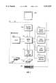
- FIG. 1is a block diagram of a portable computer system in accordance with the present invention
- FIG. 2is a block diagram of the keyboard power generator in accordance with the present invention.
- FIG. 3is an illustration of coils positioned in conjunction with keys of the keyboard of FIG. 2;
- FIG. 4is an illustration of a second embodiment of the keyboard in accordance with the present invention.
- FIG. 5is a schematic diagram illustrating the electrical connection of voltage generators in the keyboard of the present invention.
- FIG. 6is an electrical circuit of the charge pump circuitry of FIG. 5.
- FIG. 7is an electrical diagram illustrating the trickle charge circuitry of the present invention.
- FIG. 1illustrates the major components of a typical portable computer.
- the notebook personal computer 100has a plurality of components, including a central processing unit (CPU) 102.
- the CPU 102is connected to a random access memory (RAM) 104.
- the CPU 102is further connected to a graphics adapter 106 for driving a display 108, preferably a liquid crystal display (LCD).
- LCDliquid crystal display
- the CPU 102is also connected to a parallel interface 110, a serial interface 112 and a local area network (LAN) adapter 114.
- the parallel interface 110is adapted to control a peripheral with a parallel port such as a laser printer, among others.
- the serial interface 112is adapted to drive peripherals with serial ports, such as a modem or a mouse, among others.
- the LAN adapter 114is adapted to be connected to a local area network for sharing files with one or more computers.
- the CPU 102is also connected to a hard disk drive and floppy disk drive controller 116.
- the controller 116drives a floppy disk 117 and a hard disk drive 118.
- the CPU 102is also connected to a keyboard interface 117.
- the keyboard interface unit 117is connected with a keyboard 120 which is capable of generating electricity for the computer system 100 of FIG. 1.
- the keyboard 120is connected to the keyboard interface 119 on the motherboard of FIG. 1.
- a keyboard processor 124receives commands from the keyboard interface 119.
- the keyboard processor 124in turn drives a buffer 122 which eventually provides information back to the keyboard interface 119.
- the keyboard processor 124is further connected to a scan matrix 140.
- the scan matrix 140is made up of crossing lines, each connected to the keyboard processor 124. The crossing lines of the scan matrix 140 are adapted to be shorted together by user actuations at the keys 123.
- Each key 123 of the keyboard 120has a key cap 126.
- the key cap 126in turn has a stem 125 having a magnet 128.
- the key cap 126is further suspended above the scanned matrix 140 by a spring 127 which provides a return action after a user has depressed the key cap 126.
- coils mounted on printed circuit boards 130 and 132are positioned adjacent to the ends ofthe magnet 128.
- the magnet 128moves relative to the coils on the printed circuit boards 130 and 132.
- Such movementgenerates a predetermined amount of electricity.
- the energyis captured into a small battery which can power the notebook computer 100 for brief periods. As the small battery is discharged rather than the main battery, the capacity of the main battery is conserved to allow the portable personal computer 100 to operate in an extended manner.
- the switch 126closes a contact between the crossing lines of the scanned matrix 140.
- the keyboard processor 124can determine the coordinates of the pressed switch, and therefore the activated key. This is done in the form of a scan code, which is transmitted via the buffer 122 to the keyboard interface 119.
- the keyboard interface 119communicates to the CPU 102 which key has been depressed. Conversion of the scanned coding to the corresponding character is carried out by a program called a keyboard driver. Using this method, different keyboard layouts may be realized without requiring that the keyboard hardware be changed. Therefore, various languages can be realized by simply adjusting the keyboard driver for the language concerned. In this manner, the user can issue commands or generate data to the computer 100 as he or she types on the keyboard 120.
- the printed circuit board plates 130 or 132are illustrated in more detail in FIG. 3.
- the printed circuit board 130has a plurality of copper coils 150 and 152 etched thereon. These copper coils are positioned at the end of the magnet 128 of FIG. 2 such that, when the magnet 128 traverses over the coils 150 and 152, induced energy in the form of a voltage is observed at the output of the coils 150 and 152.
- the outputs of a plurality of the circuit boards 130are summed and multiplied into a charging voltage level, as shown in FIG. 5.
- FIG. 4a second embodiment of the present invention is illustrated.
- a plurality of key caps 202 and 206are mounted on a keyboard 201. Further, each of the key caps 202 and 206 are coupled to magnets 203-205 and 207-209, respectively.
- the coupling of multiple magnets per each of key caps 202 and 206increases the voltage output at the coils located on printed circuit boards 210, 212 and 214. In this manner, since keys are typically pressed in a sequence, one coil set can reside between two keys in adjacent printed circuit boards, such as 210 and 212 or 212 and 214, thereby reducing the number of printed circuit boards required.
- the deployment of magnets 203, 205, 207 and 209thus enables more energy to be generated by the keyboard power generator of the present invention.
- the collective output of the keys on the keyboard 201are multiplied to generate a suitable charging voltage, as illustrated in FIG. 5.
- each of the keysis represented as a voltage generator 216-224.
- the collective voltage outputs from keypad generators 216-224are provided to a charge pump unit 226.
- the charge pump 226in turn increases the small voltage generated by the voltage generators 216-224 to a sufficient level where it can charge a battery.
- the charge pump 226 of FIG. 5is illustrated in more detail in FIG. 6.
- the charge pump 226consists of an oscillator 268 and subsequent circuitry to triple the input voltage.
- the oscillator 268drives a first crossover lockout (LO) circuit 266 and a second XLO 256.
- the output of the XLO 266is provided to a totem pole circuit consisting of a P-channel MOSFET 264 and an N-channel MOSFET 262.
- One pin of the P-channel MOSFET 264is connected to one input of a diode 242.
- the output of the diode 242is in turn connected to the second pin ofthe P MOSFET 264 via a capacitor 260.
- the output of the capacitor 260is also connected to one pin ofthe N-channel MOSFET 262, while the other pin of the N-channel MOSFET 262 is connected to ground.
- a diode 240is connected between the input to the diode D1 and ground. In this manner, the diode D1 generates a voltage that is twice the input voltage.
- the second output of the oscillator 268drives a second XLO 256 in a similar manner.
- the output of the XLO 256drives a P-channel MOSFET 254 and an N-channel MOSFET 252.
- the P-channel transistor 254 and N-channel transistor 252are connected together via a capacitor 250.
- the other input of the capacitor 250is connected to the output of a diode 244.
- the input of the diode 244is connected to output of the diode 242.
- the output of the diode 244is connected to the input of a diode 246.
- the output of the diode 246in turn is connected to the output of a diode 248, whose input is connected to ground.
- the output of the diode 246is a voltage that is greater than the voltage at the N-terminal.
- the voltage step-upis performed by charging the capacitor 260, and then switching the charged capacitor 260 in series with the input voltage to produce a higher voltage at the output of the diode 242.
- the output of the diode 242becomes nominally twice the input voltage IN.
- the same operationis performed at the output of the diode 244 to produce a tripled voltage.
- the charge pump of FIG. 6produces an output that is a multiple of the input voltage.
- the multiplied voltage available at the OUT terminal of FIG. 6is used to charge a small battery, as further shown in FIG. 7.
- FIG. 7a trickle-charge circuit for charging the battery of the present invention is shown in detail.
- the output of the voltage multiplier of FIG. 6is provided to a diode 280.
- the output of the diode 280is provided to a resistor 290.
- the resistor 290is further connected to the battery 294 which stores the energy produced by the key strokes for eventual usage by the personal computer 100.
- the energy provided by the keyboard of the present inventioncan then be used to lengthen the operating period of the portable computer, or alternative, can be used to reduce the size of the primary battery so as to result in a lighter portable computer.
- the present inventionallows longer operating period between recharge, faster processing speeds, more powerful peripherals, larger screens and other advanced features for portable computers while keeping weight and size down.
- the present inventioncontemplates that more complex battery charger controllers such as a MAX712 or a MAX713, available from Maxim Integrated Products, Inc. in Sunnyvale, Calif., may be utilized. These devices may perform fast charge of the batteries based on the voltage slope, temperature and timer of fast charge cut-off Further, these controllers may be able to charge the battery in a linear mode while supplying the battery's load as necessary.
- a MAX712 or a MAX713available from Maxim Integrated Products, Inc. in Sunnyvale, Calif.
- the general system configuration of the present inventiondiscloses one possible implementation of the present invention for the display, navigation, manipulation and editing of text and image data in a graphical user interface.
- the general system configurationdescribes a computer display system which may be in the form of a personal computer, workstation, or dedicated processor system to permit the user to utilize the teachings of the present invention. No particular computer hardware is described within this specification, and the general system configuration description is intended to encompass a broad range of possible data processing systems in which the present invention may be implemented.
- piezoelectric sourcescould be used as the mechanical to electrical energy converter, as could other capacitive or inductive methods.
- a power supplycould provide computer power directly from the energy provided, or could charge the battery directly. While this power source is especially applicable to portable computers, it can be used to augment the power in other computers, such as desktops, as well.
Landscapes
- Engineering & Computer Science (AREA)
- Theoretical Computer Science (AREA)
- General Engineering & Computer Science (AREA)
- Physics & Mathematics (AREA)
- General Physics & Mathematics (AREA)
- Human Computer Interaction (AREA)
- Power Sources (AREA)
Abstract
Description
Claims (23)
Priority Applications (1)
| Application Number | Priority Date | Filing Date | Title |
|---|---|---|---|
| US08/885,089US5911529A (en) | 1997-06-30 | 1997-06-30 | Typing power |
Applications Claiming Priority (1)
| Application Number | Priority Date | Filing Date | Title |
|---|---|---|---|
| US08/885,089US5911529A (en) | 1997-06-30 | 1997-06-30 | Typing power |
Publications (1)
| Publication Number | Publication Date |
|---|---|
| US5911529Atrue US5911529A (en) | 1999-06-15 |
Family
ID=25386111
Family Applications (1)
| Application Number | Title | Priority Date | Filing Date |
|---|---|---|---|
| US08/885,089Expired - LifetimeUS5911529A (en) | 1997-06-30 | 1997-06-30 | Typing power |
Country Status (1)
| Country | Link |
|---|---|
| US (1) | US5911529A (en) |
Cited By (28)
| Publication number | Priority date | Publication date | Assignee | Title |
|---|---|---|---|---|
| WO2000057800A1 (en)* | 1999-03-27 | 2000-10-05 | Hendricksen Mark W | Therapeutic applicator system for computer users |
| US6301626B1 (en)* | 1998-10-29 | 2001-10-09 | Sun Microsystems, Inc. | System for dynamic configuration of an input device by downloading an input device layout from server if the layout is not already display on the input device |
| US6491457B2 (en) | 1999-12-28 | 2002-12-10 | Adel Abdel Aziz Ahmed | Apparatus and method for deriving electric power efficiently from a keyboard |
| US20030080938A1 (en)* | 2001-10-25 | 2003-05-01 | Bin Lian | Self-powered wireless device |
| US20030143963A1 (en)* | 2000-05-24 | 2003-07-31 | Klaus Pistor | Energy self-sufficient radiofrequency transmitter |
| US6700310B2 (en) | 2000-10-13 | 2004-03-02 | Lear Corporation | Self-powered wireless switch |
| US6820206B1 (en)* | 2001-11-20 | 2004-11-16 | Palmone, Inc. | Power sharing between portable computer system and peripheral device |
| US6930848B1 (en)* | 2002-06-28 | 2005-08-16 | Western Digital Technologies, Inc. | Back EMF voltage transducer/generator to convert mechanical energy to electrical energy for use in small disk drives |
| US6933655B2 (en) | 2000-10-13 | 2005-08-23 | Lear Corporation | Self-powered wireless switch |
| US20050226669A1 (en)* | 2004-04-13 | 2005-10-13 | Cheng Wen L | Keyboard having key floating device |
| US20060202868A1 (en)* | 2000-10-17 | 2006-09-14 | Henty David L | Computer system with enhanced range passive wireless keyboard |
| US20070200778A1 (en)* | 2006-02-28 | 2007-08-30 | Henty David L | Passive wireless keyboard powered by key activation |
| US20070222584A1 (en)* | 2001-10-11 | 2007-09-27 | Enocean Gmbh | Wireless sensor system |
| WO2007098274A3 (en)* | 2006-02-27 | 2008-01-10 | David L Henty | Computer system with enhanced range passive wireless keyboard |
| CN100533351C (en)* | 2007-08-03 | 2009-08-26 | 敬德强 | A keyboard with a generator |
| US20100239345A1 (en)* | 2009-03-21 | 2010-09-23 | Hong Fu Jin Precision Industry (Shenzhen) Co., Ltd | Keyboard |
| US20110142522A1 (en)* | 2009-12-11 | 2011-06-16 | Bert Yeh | Typing to generate electricity |
| US20110169444A1 (en)* | 2010-01-08 | 2011-07-14 | Yi-Chen Wang | Electronic device and chargeable keyboard |
| US20110285660A1 (en)* | 2010-05-18 | 2011-11-24 | Prabhu Krishnanand | Touch screen power generation |
| CN103683796A (en)* | 2013-12-29 | 2014-03-26 | 苏州市牛勿耳关电器科技有限公司 | Keyboard generating device |
| US20140253452A1 (en)* | 2013-03-08 | 2014-09-11 | International Business Machines Corporation | Wireless keyboard |
| WO2015038103A1 (en)* | 2013-09-10 | 2015-03-19 | Pearl Capital Developments Llc | Generator button for electronic devices |
| US9305252B1 (en)* | 2012-07-13 | 2016-04-05 | The United States Of America As Represented By The Administrator Of The National Aeronautics And Space Administration | Systems and methods for RFID-enabled pressure sensing apparatus |
| USRE46499E1 (en) | 2001-07-03 | 2017-08-01 | Face International Corporation | Self-powered switch initiation system |
| WO2020198900A1 (en)* | 2019-03-29 | 2020-10-08 | 北京理工大学 | Self-powered wireless keyboard |
| US10990183B2 (en) | 2010-04-05 | 2021-04-27 | Tactile Displays, Llc | Interactive display with tactile feedback |
| US10990184B2 (en)* | 2010-04-13 | 2021-04-27 | Tactile Displays, Llc | Energy efficient interactive display with energy regenerative keyboard |
| US12321530B2 (en)* | 2023-10-04 | 2025-06-03 | Dell Products Lp | System and method for a power sustainability keyboard with solenoidal energy harvester device |
Citations (2)
| Publication number | Priority date | Publication date | Assignee | Title |
|---|---|---|---|---|
| US5220318A (en)* | 1988-12-22 | 1993-06-15 | Ampex Corporation | Apparatus for selectively varying keyboard switching force |
| US5615393A (en)* | 1993-03-15 | 1997-03-25 | Elonex I.P. Holdings Ltd. | Computer system having a cordless keyboard and an induction coil in a plug-in electronic card module |
- 1997
- 1997-06-30USUS08/885,089patent/US5911529A/ennot_activeExpired - Lifetime
Patent Citations (2)
| Publication number | Priority date | Publication date | Assignee | Title |
|---|---|---|---|---|
| US5220318A (en)* | 1988-12-22 | 1993-06-15 | Ampex Corporation | Apparatus for selectively varying keyboard switching force |
| US5615393A (en)* | 1993-03-15 | 1997-03-25 | Elonex I.P. Holdings Ltd. | Computer system having a cordless keyboard and an induction coil in a plug-in electronic card module |
Non-Patent Citations (12)
| Title |
|---|
| Bassak, Gil, Running on Empty , Mobile Computing and Communications, Jun. 1997, pp. 76 85.* |
| Bassak, Gil, Running on Empty, Mobile Computing and Communications, Jun. 1997, pp. 76-85. |
| MAXIM, MAX712 Linear Mode Evaluation Kit, MAXIM Integrated Products, Jan. 1997, pp. 1 6.* |
| MAXIM, MAX712 Linear-Mode Evaluation Kit, MAXIM Integrated Products, Jan. 1997, pp. 1-6. |
| MAXIM, MAX713 Switch Mode Evaluation Kit, MAXIM Integrated Products, Jan. 1997, pp. 1 4.* |
| MAXIM, MAX713 Switch-Mode Evaluation Kit, MAXIM Integrated Products, Jan. 1997, pp. 1-4. |
| MAXIM, NiCd/NiMH Battery Fast Charge Controllers, MAXIM Integrated Products, Jan. 1997, pp. 1 18.* |
| MAXIM, NiCd/NiMH Battery Fast Charge Controllers, MAXIM Integrated Products, Jan. 1997, pp. 1-18. |
| MICREL Semiconductor, MIC2660, IttyBitty Charge Pump, MICREL Incorporated, 1996, Section 10, pp. 10 14.* |
| MICREL Semiconductor, MIC2660, IttyBitty™ Charge Pump, MICREL Incorporated, 1996, Section 10, pp. 10-14. |
| Shen, Liang Chi, Applied Electromagnetism , PWS Engineering, 1987, Chap. 16, pp. 488 497.* |
| Shen, Liang Chi, Applied Electromagnetism, PWS Engineering, 1987, Chap. 16, pp. 488-497. |
Cited By (43)
| Publication number | Priority date | Publication date | Assignee | Title |
|---|---|---|---|---|
| US6301626B1 (en)* | 1998-10-29 | 2001-10-09 | Sun Microsystems, Inc. | System for dynamic configuration of an input device by downloading an input device layout from server if the layout is not already display on the input device |
| WO2000057800A1 (en)* | 1999-03-27 | 2000-10-05 | Hendricksen Mark W | Therapeutic applicator system for computer users |
| US6491457B2 (en) | 1999-12-28 | 2002-12-10 | Adel Abdel Aziz Ahmed | Apparatus and method for deriving electric power efficiently from a keyboard |
| US20030143963A1 (en)* | 2000-05-24 | 2003-07-31 | Klaus Pistor | Energy self-sufficient radiofrequency transmitter |
| US9614553B2 (en) | 2000-05-24 | 2017-04-04 | Enocean Gmbh | Energy self-sufficient radiofrequency transmitter |
| US9887711B2 (en) | 2000-05-24 | 2018-02-06 | Enocean Gmbh | Energy self-sufficient radiofrequency transmitter |
| US6933655B2 (en) | 2000-10-13 | 2005-08-23 | Lear Corporation | Self-powered wireless switch |
| US6700310B2 (en) | 2000-10-13 | 2004-03-02 | Lear Corporation | Self-powered wireless switch |
| US7525453B2 (en) | 2000-10-17 | 2009-04-28 | Henty David L | Computer system with enhanced range passive wireless keyboard |
| US20060202868A1 (en)* | 2000-10-17 | 2006-09-14 | Henty David L | Computer system with enhanced range passive wireless keyboard |
| USRE46499E1 (en) | 2001-07-03 | 2017-08-01 | Face International Corporation | Self-powered switch initiation system |
| US20070222584A1 (en)* | 2001-10-11 | 2007-09-27 | Enocean Gmbh | Wireless sensor system |
| US7777623B2 (en) | 2001-10-11 | 2010-08-17 | Enocean Gmbh | Wireless sensor system |
| US20030080938A1 (en)* | 2001-10-25 | 2003-05-01 | Bin Lian | Self-powered wireless device |
| US8261109B2 (en) | 2001-11-20 | 2012-09-04 | Hewlett-Packard Development Company, L.P. | Power sharing between portable computer system and peripheral devices |
| US6820206B1 (en)* | 2001-11-20 | 2004-11-16 | Palmone, Inc. | Power sharing between portable computer system and peripheral device |
| US7536572B1 (en)* | 2001-11-20 | 2009-05-19 | Palm, Inc. | Power sharing between portable computer system and peripheral devices |
| US6930848B1 (en)* | 2002-06-28 | 2005-08-16 | Western Digital Technologies, Inc. | Back EMF voltage transducer/generator to convert mechanical energy to electrical energy for use in small disk drives |
| US20050226669A1 (en)* | 2004-04-13 | 2005-10-13 | Cheng Wen L | Keyboard having key floating device |
| US6962452B2 (en)* | 2004-04-13 | 2005-11-08 | Wen Lung Cheng | Keyboard having key floating device |
| WO2007098274A3 (en)* | 2006-02-27 | 2008-01-10 | David L Henty | Computer system with enhanced range passive wireless keyboard |
| US20070200778A1 (en)* | 2006-02-28 | 2007-08-30 | Henty David L | Passive wireless keyboard powered by key activation |
| US7535424B2 (en) | 2006-02-28 | 2009-05-19 | Henty David L | Passive wireless keyboard powered by key activation |
| CN100533351C (en)* | 2007-08-03 | 2009-08-26 | 敬德强 | A keyboard with a generator |
| US20100239345A1 (en)* | 2009-03-21 | 2010-09-23 | Hong Fu Jin Precision Industry (Shenzhen) Co., Ltd | Keyboard |
| US8162551B2 (en)* | 2009-03-21 | 2012-04-24 | Hong Fu Jin Precision Industry (Shenzhen) Co., Ltd. | Keyboard using kinetic energy of keystroke to generate electricity |
| US20110142522A1 (en)* | 2009-12-11 | 2011-06-16 | Bert Yeh | Typing to generate electricity |
| US8446122B2 (en)* | 2010-01-08 | 2013-05-21 | Darfon Electronics Corp. | Electronic device and chargeable keyboard with solar cells located on a keyboard |
| US20110169444A1 (en)* | 2010-01-08 | 2011-07-14 | Yi-Chen Wang | Electronic device and chargeable keyboard |
| US10990183B2 (en) | 2010-04-05 | 2021-04-27 | Tactile Displays, Llc | Interactive display with tactile feedback |
| US10996762B2 (en) | 2010-04-05 | 2021-05-04 | Tactile Displays, Llc | Interactive display with tactile feedback |
| US10990184B2 (en)* | 2010-04-13 | 2021-04-27 | Tactile Displays, Llc | Energy efficient interactive display with energy regenerative keyboard |
| US20110285660A1 (en)* | 2010-05-18 | 2011-11-24 | Prabhu Krishnanand | Touch screen power generation |
| US9305252B1 (en)* | 2012-07-13 | 2016-04-05 | The United States Of America As Represented By The Administrator Of The National Aeronautics And Space Administration | Systems and methods for RFID-enabled pressure sensing apparatus |
| US9785877B1 (en) | 2012-07-13 | 2017-10-10 | The United States Of America As Represented By The Administrator Of The National Aeronautics And Space Administration | Systems and methods for RFID-enabled pressure sensing apparatus |
| US20140253452A1 (en)* | 2013-03-08 | 2014-09-11 | International Business Machines Corporation | Wireless keyboard |
| US9524033B2 (en)* | 2013-03-08 | 2016-12-20 | International Business Machines Corporation | Wireless keyboard |
| WO2015038103A1 (en)* | 2013-09-10 | 2015-03-19 | Pearl Capital Developments Llc | Generator button for electronic devices |
| US10312039B2 (en)* | 2013-09-10 | 2019-06-04 | Apple Inc. | Generator button for electronic devices |
| US20160217953A1 (en)* | 2013-09-10 | 2016-07-28 | Apple Inc. | Generator Button for Electronic Devices |
| CN103683796A (en)* | 2013-12-29 | 2014-03-26 | 苏州市牛勿耳关电器科技有限公司 | Keyboard generating device |
| WO2020198900A1 (en)* | 2019-03-29 | 2020-10-08 | 北京理工大学 | Self-powered wireless keyboard |
| US12321530B2 (en)* | 2023-10-04 | 2025-06-03 | Dell Products Lp | System and method for a power sustainability keyboard with solenoidal energy harvester device |
Similar Documents
| Publication | Publication Date | Title |
|---|---|---|
| US5911529A (en) | Typing power | |
| CN100350350C (en) | Electronic device and its control | |
| CN102801188B (en) | Power supply control method and electronic device using same | |
| CN100533351C (en) | A keyboard with a generator | |
| CN102969891A (en) | Power converting circuit of a display driver | |
| JP2005115771A5 (en) | ||
| JPH05119876A (en) | Electronic device and integrated circuit included in the device | |
| JP2005228318A (en) | Wireless input device for communicating user input to computer, and its communication method and computer system | |
| TWI376592B (en) | Computer system | |
| US6774502B2 (en) | Battery powered laptop computer with an implementation for converting keyboard keystroke motion into current for auxiliary recharging of battery | |
| JPH03109625A (en) | Electronics | |
| US20110169444A1 (en) | Electronic device and chargeable keyboard | |
| TWM381101U (en) | Power saving device and all-in-one pc having the same | |
| US7149911B2 (en) | Portable computer with desktop type processor | |
| CN201247425Y (en) | Computer capable of switching memory apparatus | |
| CN102375630B (en) | Surface capacitive touch device and control method thereof | |
| CN1147981C (en) | Mouse with power generator | |
| CN2696200Y (en) | power converter | |
| CN120749971A (en) | Charging system, electronic device protective case and stylus | |
| Shirriff | The quiet remaking of computer power supplies: A half century ago, better transistors and switching regulators revolutionized the design of computer power supplies | |
| CN204926090U (en) | Control system based on developments password and USBKEY | |
| JPH04370615A (en) | input device | |
| CN217282695U (en) | Low-power consumption intelligence lock system | |
| CN101201685A (en) | Charging type remote controller | |
| CN101295203A (en) | Creepage eliminating method |
Legal Events
| Date | Code | Title | Description |
|---|---|---|---|
| AS | Assignment | Owner name:COMPAQ COMPUTER CORPORATION, TEXAS Free format text:ASSIGNMENT OF ASSIGNORS INTEREST;ASSIGNOR:CRISAN, ADRIAN;REEL/FRAME:008968/0198 Effective date:19980115 | |
| STCF | Information on status: patent grant | Free format text:PATENTED CASE | |
| AS | Assignment | Owner name:COMPAQ INFORMATION TECHNOLOGIES GROUP, L.P., TEXAS Free format text:ASSIGNMENT OF ASSIGNORS INTEREST;ASSIGNOR:COMPAQ COMPUTER CORPORATION;REEL/FRAME:012418/0222 Effective date:20010620 | |
| FPAY | Fee payment | Year of fee payment:4 | |
| AS | Assignment | Owner name:HEWLETT-PACKARD DEVELOPMENT COMPANY, L.P., TEXAS Free format text:CHANGE OF NAME;ASSIGNOR:COMPAQ INFORMATION TECHNOLOGIES GROUP, LP;REEL/FRAME:015000/0305 Effective date:20021001 | |
| FPAY | Fee payment | Year of fee payment:8 | |
| FPAY | Fee payment | Year of fee payment:12 | |
| AS | Assignment | Owner name:HTC CORPORATION, TAIWAN Free format text:ASSIGNMENT OF ASSIGNORS INTEREST;ASSIGNOR:HEWLETT-PACKARD DEVELOPMENT COMPANY, L.P.;REEL/FRAME:027531/0218 Effective date:20111213 |