US5911059A - Method and apparatus for testing software - Google Patents
Method and apparatus for testing softwareDownload PDFInfo
- Publication number
- US5911059A US5911059AUS08/768,813US76881396AUS5911059AUS 5911059 AUS5911059 AUS 5911059AUS 76881396 AUS76881396 AUS 76881396AUS 5911059 AUS5911059 AUS 5911059A
- Authority
- US
- United States
- Prior art keywords
- target
- processor
- hardware simulator
- processor emulator
- emulator
- Prior art date
- Legal status (The legal status is an assumption and is not a legal conclusion. Google has not performed a legal analysis and makes no representation as to the accuracy of the status listed.)
- Expired - Fee Related
Links
Images


Classifications
- G—PHYSICS
- G06—COMPUTING OR CALCULATING; COUNTING
- G06F—ELECTRIC DIGITAL DATA PROCESSING
- G06F11/00—Error detection; Error correction; Monitoring
- G06F11/36—Prevention of errors by analysis, debugging or testing of software
- G06F11/3698—Environments for analysis, debugging or testing of software
- G—PHYSICS
- G06—COMPUTING OR CALCULATING; COUNTING
- G06F—ELECTRIC DIGITAL DATA PROCESSING
- G06F11/00—Error detection; Error correction; Monitoring
- G06F11/22—Detection or location of defective computer hardware by testing during standby operation or during idle time, e.g. start-up testing
- G06F11/26—Functional testing
- G06F11/261—Functional testing by simulating additional hardware, e.g. fault simulation
- G—PHYSICS
- G06—COMPUTING OR CALCULATING; COUNTING
- G06F—ELECTRIC DIGITAL DATA PROCESSING
- G06F11/00—Error detection; Error correction; Monitoring
- G06F11/36—Prevention of errors by analysis, debugging or testing of software
- G06F11/362—Debugging of software
- G06F11/3632—Debugging of software of specific synchronisation aspects
- G—PHYSICS
- G06—COMPUTING OR CALCULATING; COUNTING
- G06F—ELECTRIC DIGITAL DATA PROCESSING
- G06F11/00—Error detection; Error correction; Monitoring
- G06F11/36—Prevention of errors by analysis, debugging or testing of software
- G06F11/362—Debugging of software
- G06F11/3648—Debugging of software using additional hardware
- G06F11/3652—Debugging of software using additional hardware in-circuit-emulation [ICE] arrangements
Definitions
- the present inventionrelates generally to computer hardware simulators, and, more specifically, to a system and method for the simulation of systems that combine hardware and software interaction.
- An embedded systemmay typically include a microprocessor executing instructions and interacting with an application specific integrated circuit (ASIC) or a custom Integrated Circuit (IC).
- ASICapplication specific integrated circuit
- ICcustom Integrated Circuit
- the microprocessor used in the systemis designated herein as a target microprocessor.
- the external circuitry that interacts with the target microprocessor, whether it is the ASIC, custom IC, or some other form of electronic circuitry,is designated herein as the target circuitry.
- the combination of the target circuitry and the target microprocessoris designated herein as the target hardware.
- the software program that is intended to be executed by the target microprocessoris designated herein as the target program.
- the first system prototypeincluding the target hardware and the target program, is typically close in form, fit, and function to the end product.
- the target hardware prototypeswould therefore include the ASIC and custom IC designs, which were fabricated and passed their respective qualification and acceptance tests at the foundry.
- the target programis typically designed, written, and tested, module by module.
- the module integration processalso involves testing of the integrated software modules.
- the target hardwaremay not be available at the time of the software development, it is not possible to test the interaction of the target hardware and the target program.
- pieces of the designare "stubbed out," or mockups built to substitute for anticipated missing parts of the target hardware.
- the term “stubbed out”refers to a mock response to a program call to a location in the yet unbuilt circuitry.
- the programmermust program a return command that causes the target program to ignore the lack of a true response from the target circuitry.
- the substitution of mocked up target hardwarerequires further interpretation of the original hardware design specifications. It is common to find that no single combined software system integration occurs before the software is loaded onto the hardware prototype, let alone tested as a whole (stubbed out or otherwise).
- the hardware and software components of a target system designare brought together for the first time when the prototype target hardware has been fabricated. Because of the prior unavailability of the actual target hardware, one often finds that the target program loaded at the time of the integration of the prototype target hardware and software does not work. It is common to find that the integration problems are strictly due to software complications alone. This may cause a significant delay in the software development due to the problems in the target program. Other problems with the integration may be caused by the interaction of the target hardware with the target program. Consequently, considering the large cost of ASIC and custom IC design, and the relatively low cost ease of software modification, it is common that the software will be force-fitted to the target hardware prototype, thereby increasing the overall planned software development time.
- a number of approacheshave been developed in an attempt to alleviate or at least minimize the software/hardware integration problems.
- One approachis to simulate the hardware using a computer hardware simulator.
- the hardware simulatoris a software program that simulates the responses of the target hardware and is implemented entirely in software.
- the target hardware and target programare simulated entirely by computer software.
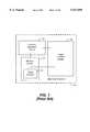
- the hardware simulation method of verifying the target systemis illustrated in FIG. 1.
- a hardware simulator 20is a software program that accepts a description of the target hardware, including electrical and logical properties of the target microprocessor and the target circuitry.
- the target hardware designmay be specified graphically by schematic diagrams or by a hardware description language (HDL), such as VHDL.
- HDLhardware description language
- the hardware simulator 20is a commercially available product that includes a target program 22 that is compiled into object code, and the object code is downloaded into a processor memory model 24 within the hardware simulator 20.
- a processor functional model 26is a software description, including the electrical and logical properties, of the target microprocessor, while a target circuitry functional model 28 provides a model of the target circuitry, such as an ASIC, or other custom or semi-custom design.
- the hardware simulator 20allows the processor functional model 26 to simulate execution of the target program 22 event by event.
- the processor functional model 26 and the target circuitry functional model 28can be specified to various levels of abstraction by a conventional HDL.
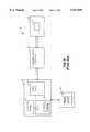
- the ISS 40includes a memory 42 that contains the target program 22.
- the ISS 40strives to guarantee functional accuracy of both instruction functions and memory references only at the processor instruction level. As a result, accuracy to detailed internal timing is sacrificed for speed.
- the speed of a typical ISS 40is on the order of 1,000-10,000 microprocessor instructions per second.
- the ISS 40executes the target program 44, but has only limited visibility to circuitry outside of the target microprocessor.
- the typical ISS 40does not represent any custom target circuitry in simulation beyond a register reference, and hence is of limited value to hardware designers or software designers that are concerned with interactions with custom hardware.
- a third approachwhich alleviates the unacceptably long run-times encountered with the processor functional model 26 (see FIG. 1), is to replace the processor functional model in the hardware simulator 20 with a physical integrated circuit (IC) microprocessor 50, as illustrated in FIG. 3.
- the microprocessor 50is connected to the hardware simulator 20 via a hardware modeler 52.
- the target program 22is contained in the memory model 24 in the hardware simulator 20, and all instructions are executed out of the memory model 24, as previously discussed with respect to FIG. 1.
- the microprocessor 50may be the actual target microprocessor or other circuit to simulate the behavior of the target microprocessor.
- the physical microprocessor 50 and the hardware modeler 52are hardware components rather than software simulations. The cost of the typical hardware modeler 52 can be quite high, ranging from $40,000 to over $200,000.
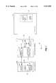
- a similar approach illustrated in FIG. 4uses a device known as a processor emulator 60 to model the target processor.
- the processor emulator 60is a hardware device that substitutes for the target microprocessor.
- Processor emulatorsare conventional devices presently available from sources such as Applied Microsystems Corporation.
- the processor emulator 60includes a microprocessor 76, which is typically the target processor.
- the processor emulator 60may also include an emulator memory 78 and a control circuit 80.
- the processor emulator 60is coupled to a workstation 84 or computer terminal by a communications link 86.
- the workstation 84may be a stand-alone computer workstation or simply a terminal coupled to a computer (not shown) to which the processor emulator 60 is also coupled.
- User interface software 88 within the workstation 84controls the display of data on the workstation and permits user input to the emulator.
- the user interface software 88 and the control circuit 80 of the processor emulator 60are conventional components of the processor emulator and add supplemental control to the prototype hardware system.
- the processor emulatoris coupled to an actual target system 62 having a memory 66 containing the target program 22, and a socket 70 for the target microprocessor.
- the processor emulator 60is coupled to the target system 62 of the target hardware by a bus system 72 and typically plugs directly into the socket 70 as a substitute for the target microprocessor.
- the emulator memory 78contains an emulator control program independent of the target program 22 in the memory 66. However, the target program 22 can also be loaded into the emulator memory 78 in what is sometimes called a memory overlay. Thus, the target program 22 can be executed from the memory 66, the emulator memory 78, or both. Execution of the target program 22 only from the emulator memory 78 allows execution of the target program without the benefit of software interaction with the target circuitry.
- the processor emulator 60may interface with reconfigurable circuitry 96 as shown in FIG. 5.
- the reconfigurable circuitry 96may be a field-programmable gate array (FPGA) which emulates target circuitry functions including the ASIC or custom IC.
- FPGAfield-programmable gate array
- Companies such as Quickturn and Aptixhave developed hardware circuit emulators which allow hardware designs to be downloaded into the reconfigurable circuitry 96 and mounted on a board-like device.
- the hardware circuit emulator 60includes a processor 76 and a memory 78.
- the target program 22is stored in the memory 78 of the emulator 60 so that it can be executed by the processor 76. This approach, known as hardware circuit emulation, allows the target system to be tested as if it is already built.
- Hardware circuit emulationhas the advantages of speed and early breadboard fabrication. However, high cost and tedium in configuration and debugging limit their application. These tools also lack hardware-software debugging visibility because access to internal registers and memory locations is not available. Also, the hardware circuit emulator 94 typically represent a major investment on the user's part, in both design effort and capital cost.
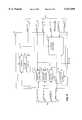
- a final approachbasically combines the use of the processor emulator 60 of FIGS. 4 and 5 with the target circuitry model 28 in the hardware simulator 20 of FIG. 3.
- This approachessentially substitutes the processor emulator 60 for the hardware modeler 52 shown in FIG. 3 except that the target program is executed out of the emulator memory 78.
- this prior art approachcouples the processor emulator 60 to an engineering workstation 100 simulating the target circuitry using a target circuitry model 28 through a communications interface 102.
- the workstation 100 with its target circuitry model 28is thus a hardware simulator 104.
- the communications interface 102provides communication between the processor emulator 60 and the hardware simulator 104 only when an event, either in the target program 22 or in the software simulation of the target circuit, requires interaction of the target program 22 and simulated target circuit.
- the processor emulator 60 and hardware simulator 104are synchronized only when an event requires interaction between the two.
- the present inventionis a system for testing and analyzing electronic systems which include a target microprocessor, simulated target circuitry, and an associated target program to be executed on the target microprocessor.
- the systemincludes a processor emulator employing a hardware device for emulating the target microprocessor and its memory subsystem.
- the processor emulatorhas a memory for storing a plurality of computer instructions that include the target program.
- the processor emulatorcommunicates with the memory to receive computer instructions from the memory.
- the systemfurther includes a hardware simulator adapted to simulate the target circuitry.
- a communications interfacecontrols communication between the processor emulator and the hardware simulator.
- the processor emulatorcommunicates with the hardware simulator using the communications interface when an event requires interaction of the target program with the target circuitry.
- a synchronization circuit contained in the communications interfacesynchronizes the processor emulator and the hardware simulator at a time other than when an event requires interaction of the target program with the target circuitry.
- the synchronization circuitcomprises a counter and a one-shot timer, the operation of which periodically causes synchronization of the processor emulator and the hardware simulator.
- the period of synchronizationmay be input by a user, or may be determined in response to computer instructions or markers contained in the target program.
- FIG. 1is a functional block diagram of a traditional hardware simulator employing a processor functional model to simulate target program execution.
- FIG. 2is a functional block diagram of a conventional instruction set simulator.
- FIG. 3is a functional block diagram of a traditional hardware simulator employing a hardware modeler to simulate target program execution.
- FIG. 4is a functional block diagram of a conventional processor emulator connected to the actual target circuitry of a target system.
- FIG. 5is a functional block diagram of a conventional processor emulator connected to reconfigurable circuitry that models the target circuitry.
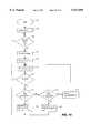
- FIG. 6is a functional block diagram of a processor emulator connected to a hardware simulator through a communications interface.
- FIG. 7is a functional block diagram of a preferred embodiment of the present invention.
- FIG. 8is a more detailed functional block diagram of the target bus watch circuit of FIG. 6.
- FIG. 9is a more detailed functional block diagram of the simulation time keeper circuit shown in FIG. 7.
- FIG. 10is a flowchart illustrating the control process executed by the controller of FIG. 7.
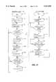
- FIG. 11is a flowchart illustrating the process of the present system for synchronizing the target program and the software simulation of the target circuitry.
- the present inventionallows for the early simulation of the target hardware and permits the parallel development of the target hardware and the target program.
- the system of the present inventionalso allows the extensive use of existing debugging tools to aid the developer in the development and integration of the target system.
- the systemcombines interacting elements of hardware and executing software, in part by physical emulation and in part by abstract software simulation.
- FIG. 7A preferred embodiment of a testing system 200 according to the present invention is shown in FIG. 7.
- the system 200includes three principal components, a processor emulator 202, a communications interface 220, and a host computer 214.
- part of the target hardwareis modeled by the processor emulator 202 and part of the target hardware is modeled by a hardware simulator 210 running on the host computer 214.
- the processor emulator 202models the target processor
- the hardware simulator 210models the target circuitry.
- the communications interface 220facilitates communication between the processor emulator 202 and the hardware simulator 210. Operation of these components is described in more detail below.
- the processor emulator 202is typically a commercially available microprocessor-based device, such as the microprocessor emulator 60 (see FIG. 4) manufactured by Applied Microsystems Corporation and others. However, it should be understood that other devices performing somewhat similar functions may be used instead of a microprocessor emulator.
- the processor emulator 202includes a processor 204 coupled to a memory 206.
- the processor 204communicates with the memory 206 to receive and execute computer instructions, including those in the target program 22, and to write data to and read data from the memory 206.
- the target program 22is stored in the memory 206 but may also be stored elsewhere, such as in an external memory (not shown in FIG. 7).
- the processor 204is the target processor itself.
- the target processor 204may, however, be realized with a separate device.
- the processor emulator 202may include additional components such as a field programmable gate array (FPGA) to form a hardware circuit emulation of the target processor.
- FPGAfield programmable gate array
- the hardware simulator 210is a conventional software program that simulates the electrical and logical activity of the target circuitry as seen by the target processor.
- the hardware simulator 210includes a processor model shell 212 which converts a sequence of processor functions to activity at simulated pins of the target processor. Such a sequence of processor functions corresponds to an instruction executed in the target program 22 which requires access to the software simulation of the target circuit. For example, assume that the target program 22 contains a memory read instruction that references an address location allocated to the address space of the target circuitry.
- a sequence of processor functionsis input to the processor model shell 212 which cause the processor model shell to change the address, data, and control lines at the simulated pins to simulate the memory read instruction in the hardware simulator 210.
- the processor model shell 212also converts interrupts or other events generated by target circuit components simulated in the hardware simulator 210 into a sequence of processor functions that allow the target program 22 executing in the processor emulator 202 to handle the interrupt or other event.
- the hardware simulator 210 and processor model shell 212typically run on a host computer 214, such as a SUN, HP, or other suitable workstation.
- the host computer 214typically contains other software tools to facilitate user interface to the system and the development of the software program which simulates the target circuitry.
- the host computer 214typically contains a software package for designing the simulation of the target circuitry either graphically using schematic diagrams or by a hardware description language (HDL).
- Software debugging toolsare likewise typically contained on the host computer 214.
- a software kernel(not shown in FIG. 7) is also typically contained on the host computer 214.
- the software kernelis coupled between the processor emulator 202 and the hardware simulator 210.
- the software kernelperforms a conversion from a first data format used by the processor emulator 202 to a second data format used by the processor model shell 212 of the hardware simulator 210. Such a conversion is typically required because the first data format is different from the second data format.
- an event in the target program 22requires interaction of the target program and the target circuitry
- this eventis communicated in the first data format to the software kernel in the host computer 214.
- the software kernelgenerates a sequence of processor functions in the second data format for use by the processor model shell 212.
- a conversion from the second data format to the first data formatis performed by the software kernel when the software program simulating the target circuitry in the hardware simulator 210 needs to interact with the target program 22 executing in the processor emulator 202.
- the communications interface 220is coupled to the processor emulator 202 and is coupled over a communication link 222 to the host computer 214.
- the communication link 222may be a serial connection, parallel connection, network connection or other suitable communications interface structure.
- the communications link 222 coupling the communications interface 220 to the host computer 214may be implemented as a set of TCP/IP sockets over an Ethernet link.
- a very low latency, dedicated, link, such as SCI or firewirewill generally be preferred in situations where the user requires real-time simulation speeds.
- the present inventionis not limited by the particular form of the communications link 222.
- the communications interface 220performs two primary functions. First, it controls communication between the processor emulator 202 executing the target program 22 and the hardware simulator 210 executing the software simulation of the target circuit. Such communication occurs when the communications interface 220 determines that an event in the target program 22 requires access to the target circuit, or when an event in the target circuit needs access to the target program 22.
- An event in the target program 22 requiring interaction with the target circuitmay be, for example, a reference (read or write) to an area of memory allocated to the target circuit, a reference to an I/O device simulated by the target circuit, or an instruction dealing with explicit hardware functions, such as RESET.
- an event in the target circuit requiring interaction with the target program 22may be, for example, an interrupt request generated by a target circuit component modeled in the hardware simulator 210.
- the second function performed by the communications interface 220is a resynchronization of the target program 22 and target circuitry. This resynchronization occurs on a periodic or other non-continuous basis even though neither the target program 22 nor the target circuit requires access to the other.
- the communications interface 220includes a controller 228 which may be implemented with a conventional microprocessor.
- the controller 228is coupled to a memory 230 which stores a control program executed by the controller.
- the controller 228is the component of the communications interface 220 which manages communications between the process emulator 202 and the hardware simulator 210 and controls the synchronization of the target program 22 and the operation of the simulated target circuit. To perform these functions, the controller 228 controls the operation of the other components of the communications interface 220, as will be described in detail below.
- the controller 228is typically a microprocessor which executes the control program in memory 230, other suitable embodiments may likewise be used to perform the required control operations.
- the communications interface 220further includes a target bus watch circuit 224 coupled to the controller 228 over a local control bus 226, which includes all the necessary data, address, and control lines.
- the target bus watch circuit 224is also coupled to the processor emulator 202 over a target bus 208 which includes all the address, data, and control lines associated with the target processor 204.
- the target bus watch circuit 224includes circuitry which allows the controller 228 to send information to and receive information from the processor emulator 202.
- the information sent to the processor emulator 202includes a HOST INTERRUPT request generated by the simulation of the target circuit running in the hardware simulator 210 as will be described in detail below.
- the target bus watch circuit 224includes circuitry which performs the function of monitoring the target bus 208 to determine if an event in the target program 22 needs access to the target circuitry.
- the communications interface 220includes a simulation time keeper circuit 232 which determines when the target program 22 will be synchronized to the operation of the hardware simulated by the hardware simulator 210 as described in detail below.
- FIG. 8is a more detailed functional block diagram showing the components of the target bus watch circuit 224 in accordance with one embodiment of the present invention.
- the target bus watch circuit 224includes a latch array 234 which stores the address ranges of the target circuit components simulated on the hardware simulator 210. This address space may also include ranges of memory or I/O addresses allocated to the target circuit.
- the address space for the target circuit componentsare typically defined and entered by the user on the host computer 214.
- the address ranges entered by the userdefine the desired address for each simulated target circuit memory and I/O component. Although address ranges are referred to herein, one skilled in the art will realize a target circuit component may have only a single address.
- the informationis communicated on the communication link 222 to the controller 228.
- the controller 228then communicates the address information on a line 235 of the local control bus 226 and stores the information in the latch array 234.
- the latch array 234provides an output 237 of the stored address ranges.
- the latch array 234is a fast memory array.
- a comparator circuit 236is coupled to the output 237 of the latch array 234, and is coupled to the address and status lines of the target bus 208.
- the comparator circuit 236functions to monitor the target bus 208 and compare the address and status requests of the target program 22 with the address ranges stored in the latch array 234. If the target program 22 requires access to a target circuit component in the hardware simulator 210, then the value on the address lines will be within an address range stored in the latch array 234. When an address or status value is within an address range stored in the latch array 234, the comparator circuit 236 provides an appropriate output on line 238.
- the target bus watch circuit 224further includes a RUN/HALT controller 240.
- the RUN/HALT controller 240performs two functions. First, the RUN/HALT controller 240 halts the execution of the target program 22 when it determines the target program requires access to the target circuit or when it determines a synchronization of the target program 22 and the simulated target circuit is required. Second, the RUN/HALT controller 240 facilitates communication between the controller 228 and the processor emulator 202. To perform these functions, the RUN/HALT controller 240 includes a dual-ported address latch 244. One port of the dual-ported address latch 244 is coupled to the address lines of the target bus 208.
- a second port of the dual-ported address latch 244is coupled to a line 253 on local control bus 226.
- the RUN/HALT controller 240includes a dual-ported status latch 250 having one port coupled to the status lines of the target bus 208 and a second port coupled to the line 253 on the local control bus 226.
- a dual-ported data latch 252has one port coupled to the data lines of the target bus 208 and the other port coupled to the line 253 on the local control bus 226.
- a signal 246is output by a latch control circuit 248 to control the operation of the dual-ported address, status, and data latches 244, 250, and 252, respectively.
- the latch control circuit 248uses the signal 246 to control which port of the dual-ported latches 244, 250, and 252 is latching event information on the line 253 and which port is subsequently serving as the output port of the dual-ported latch for that event information. Operation of the latch control circuit 248 is managed by the controller 228, which is coupled to the latch control circuit 248 through a control signal on a line 254 of the local control bus 226.
- a clock 242drives the latch control circuit 248, this clock typically being the same clock which drives the processor 204.
- the controller 228applies signals to the target address bus, status bus and/or data bus by storing the signals in the address latch 244, status latch 250, and data latch 252, respectively.
- the signalsare then applied to the appropriate bus by the corresponding latches 244, 250, 252. Transfer of information from the processor emulator 202 to the controller 228 through the latches 244, 250, 252 occurs in the reverse sequence.
- the RUN/HALT controller 240further includes a RUN/HALT state machine 256.
- the function of the RUN/HALT state machine 256is to synchronize a request to halt the processor 204 with the bus cycle of the processor. In effect, the state machine 256 effectively causes the processor 204 to go into an extended wait-state mode until the required task is accomplished.
- a request to halt the processor 204occurs in two instances. First, when the target program 22 needs access to the simulated target circuit. In that instance, the state machine 256 is coupled to the output 238 of the comparator 236. When the value of the output indicates the target program 22 needs access to the simulated target circuit, the RUN/HALT state machine 256 provides a RUN/HALT signal on a line of the target bus 208.
- This RUN/HALT signalcauses the processor 204 to halt execution of the target program 22.
- the state machine 256Immediately after outputting the RUN/HALT signal, the state machine 256 provides a TBW INTERRUPT on a line of the local control bus 226.
- the controller 228communicates the required event information on line 253 between the target program 22 and the simulated target circuit.
- the second instance where the processor 204 is halted by the state machine 256 using the RUN/HALT signalis when a synchronization of the target program 22 and the simulated target circuit is required.
- the state machine 256provides the RUN/HALT signal when it receives STK INTERRUPT from the simulation time keeper circuit 232.
- the STK INTERRUPTis output by the simulation time keeper circuit 232 when such a synchronization is required.
- the target bus watch circuit 224monitors the data address, and status lines on the target bus 208 of the processor emulator 202.
- the target bus watch circuit 224detects when the processor 204 executes a computer instruction or event in the target program 22 that includes a reference to a memory or I/O address within the address space allocated to the simulation of the target circuitry in the hardware simulator 210.
- the target bus watch circuit 224outputs the RUN/HALT signal to halt execution of the target program 22 and at the same time outputs the TBW INTERRUPT to the controller 228.
- the controller 228thereafter controls the dual-ported latches 244, 250, and 252 in the target bus watch circuit 224 to communicate required event information between the processor emulator 202 and the hardware simulator 210.
- the controllerresets the target bus watch circuit 224.
- the target bus watch circuit 224removes the RUN/HALT signal and allows continued execution of the target program 22 by the processor emulator 202.
- the target bus watch circuit 224also halts execution of the target program 22 running in the processor emulator 202 when the STK INTERRUPT is received from the simulation time keeper circuit 232.
- the controller 228controls the dual-ported latches 244, 250, and 252 in the target bus watch circuit 224 to service the HOST INTERRUPT requests generated by the simulation of the target circuitry running in the hardware simulator 210.
- the simulation time keeper circuit 232which is part of the communications interface 220, is coupled to the local control bus 226.
- the simulation time keeper circuit 232generates the STK INTERRUPT signal at appropriate times which is communicated over the local control bus 226 to the target bus watch circuit 224 and the controller 228.
- FIG. 8illustrates a preferred embodiment of the simulation time keeper circuit 232.
- the simulation time keeper circuit 232includes a counter 260.
- the controller 228is coupled to the counter 260 through the local control bus 226. Specifically, the controller 228 provides a TIME INTERVAL signal on a line 262 and a RESET signal on a line 263.
- the counteris driven by the clock signal on line 242.
- the value of the TIME INTERVAL signal on line 262determines the count of the counter 260.
- the count in the counter 260increments until it equals the value set by the TIME INTERVAL signal on line 262 (or may be decremented to zero if a decrementing counter is used).
- the counter 260provides an appropriate output on a line 265.
- This output on line 265is coupled to a one-shot timer 261.
- the one-shot timer 261outputs the STK INTERRUPT signal on a line of the local control bus 226.
- the value of the TIME INTERVAL signal 262may be determined in a number of ways. First, a user may enter the desired value on the host computer 214. This value is communicated over the communications link 222 to the controller 228 which communicates this value via the TIMER INTERVAL signal on line 262 to the counter 260. When the valve of the TIMER INTERVAL signal on line 262 is constant, the simulation time keeper circuit 232 periodically generates the STK INTERRUPT signal. The controller 228 synchronizes the processor emulator 202 and hardware simulator 210 in response to the STK INTERRUPT signal. Once this synchronization is complete, the controller 228 provides the RESET signal on line 263 which causes the counter 260 to initialize and begin a new count.
- This reset of the counter 260also changes the output on line 265 which causes the one-shot timer 261 to remove the STK INTERRUPT signal.
- the simulation time keeper circuit 232periodically generates the STK INTERRUPT signal on the local control bus 226.
- the value of the TIME INTERVAL signal on line 262may be determined by special instructions known as "markers" contained in the target program 22.
- markerscontained in the target program 22.
- a design engineerwould scan his target program 22 and insert markers at desired locations in the target program. Such markers would determine the degree of synchronization of the target program 22 from that point on. Execution of a marker in the target program 22 would result in value of the TIME INTERVAL signal on line 262 being set to the value associated with that marker.
- the markersmay set the value of the TIME INTERVAL signal on line 262 in a variety of different ways. For example, a marker address may be stored in the address space in the latch array 234.
- the controller 228controls the target bus watch circuit to receive information associated with the marker from the processor emulator 202.
- This informationincludes the special marker address on the target address bus which is processed by the controller 228 and recognized as a marker.
- the controller 228sets the value of the TIME INTERVAL signal on line 262 to the value of the data contained on the target data bus of the processor emulator 202.
- a plurality of marker addressescould be stored in the address space in the latch array 234.
- the controller 228Upon receipt of a specific marker address, the controller 228 could then set the TIME INTERVAL signal on line 262 to a value associated with that particular marker address.
- This methodallows a design engineer to determine how each section of the target program 22 will be synchronized with the simulation of the target circuitry in the hardware simulator 210. Setting the time interval to zero would cause synchronization to occur at the execution of each instruction. Thus, with this method the synchronization is not periodic.
- the target bus watch circuit 224Upon detection of an event requiring interaction of the target program 22 and the target circuit, the target bus watch circuit 224 communicates the RUN/HALT signal on the target bus 208. The RUN/HALT signal causes the processor 204 to halt execution of the target program 22. When such an event is detected, the target bus watch circuit 224 also communicates the TBW INTERRUPT signal over the local control bus 226 to the controller 228.
- the controller 228communicates the required event information (in the first data format) over the communications link 222 to the host computer 214.
- the software kernel in the host computer 214converts this event into the second data format used by the processor model shell 212.
- the processor model shell 212either writes to or reads from the simulated target circuitry. However, for an event such as a RESET no information need be read or written, so the processor model shell 212 would merely reset the simulation of the target circuit.
- the processor model shell 212provides any information required by the event to the software kernel, which communicates this information and an acknowledgment of completion of the event over the communications link 222 to the controller 228.
- the controller 228Upon receipt of this acknowledgment, the controller 228 activates the RESET signal on line 258 which causes the target bus watch circuit 224 to release the RUN/HALT signal and allow continued execution of the target program 22. If the event was a READ instruction, the controller 228 stores the data from the READ in the memory 206 of the processor emulator 202 before releasing the RUN/HALT signal.
- the RUN/HALT state machine 256 in the bus watch circuit 224In response to the STK INTERRUPT signal, from the simulation time keeper circuit 232, the RUN/HALT state machine 256 in the bus watch circuit 224 outputs the RUN/HALT signal to halt execution of the target program 22.
- the controller 228also receives the STK INTERRUPT signal across the local control bus 226. When the controller 228 receives the STK INTERRUPT signal, the controller sends a command in the first data format over the communications link 222 to the host computer 214. This command is converted by the software kernel into the second data format for use by the processor model shell 212. The command tells the hardware simulator 210 it is time to synchronize with the target program 22.
- the hardware simulator 210executes the software simulation of the target circuit until a simulation clock count contained in the simulation equals a target clock count in the target program 22 or until the simulation completes a pending transaction. Once the two clock counts are equal, the hardware simulator 210 communicates a clock synchronization acknowledge signal to the controller 228. Upon receiving the clock synchronization acknowledge signal, the controller 228 activates the RESET signal on line 258 which causes the target bus watch circuit 224 to release the RUN/HALT signal and allow continued execution of the target program 22.
- the controller 228also services interrupts from the hardware simulator 210.
- Interrupts from the hardware simulator 210correspond to interrupts generated by the target circuitry. Such interrupts may, for example, represent the closure or opening of a switch, the pressing of a key on a keyboard, or may be a periodic request for service by the processor.
- Interrupts generated by the target circuitryare received by the processor model shell 212 and communicated to the software kernel, which converts the interrupt to a HOST INTERRUPT request in the first data format. This HOST INTERRUPT request is communicated over the communications link 222 to the controller 228.
- the controller 228outputs the HOST INTERRUPT on line 255 to the target bus watch circuit 224 and controls the dual-ported latches 244, 250, and 252 to communicate the HOST INTERRUPT request to the processor emulator 202.
- the programmertypically creates an interrupt handling routine, which is invoked asynchronously upon receipt of the HOST INTERRUPT request.
- Facilities in the processor emulator 202exist for interrupt masking, fully supporting the hardware equivalent found in the target system. These facilities ensure that the system 200 is compatible with interrupt driven code.
- FIG. 10is a flowchart of the control program executed by the controller 228 in one embodiment of the present invention.
- the control programbegins in step 300 and proceeds immediately to step 302.
- the controller 228initializes the target bus watch circuit 224, simulation time keeper circuit 232, and the processor emulator 202. Initialization of the target bus watch circuit 224 causes that circuit to activate the RUN/HALT signal and thereby place the processor 204 in a wait-state mode.
- the controller 228waits to receive a message from the host computer 214 in step 304.
- the programproceeds to step 306 and processes that message.
- step 306the controller 228 may, for example, be instructed by the host computer 214 to load the memory 206 contained in the process emulator 202 with computer instructions, including the target program 22, or to transfer data into the memory 206.
- the programproceeds to step 308 where the controller 228 instructs the target bus watch circuit 224 to release the processor 204 to execute the target program 22.
- step 310the controller 228 waits to receive an interrupt from: (1) the target bus watch circuit 224 in the form of the TBW INTERRUPT; (2) the simulation time keeper circuit 232 in the form of the STK INTERRUPT, or (3) the hardware simulator 210 in the form of the HOST INTERRUPT.
- step 310the control program proceeds to step 312 and determines if one of these interrupts has been received. If this determination is negative, the program goes back to step 310. The controller 228 continues to wait until such an interrupt is received. Once an interrupt is received the determination in step 312 is positive and the control program proceeds immediately to step 314. In step 314, the control program determines whether the interrupt is the TBW INTERRUPT from the target bus watch circuit 224.
- step 316the controller 228 processes the TBW INTERRUPT and provides the information required by the event causing the TBW INTERRUPT to the target program 22 or to the hardware simulator 210, as required.
- a TBW INTERRUPT from the target bus watch circuit 224does not always require information to be transferred from the target program 22 to the hardware simulator 210, or data to be read from the hardware simulator 210 into the target program 22.
- the TBW INTERRUPTcould be a RESET of the simulated target circuitry in the hardware simulator 210. In such a case, the simulated target circuit need merely be initialized, and no information need be communicated between the target program 22 and the hardware simulator 210. From step 316, the control program proceeds back to step 310.
- step 318the controller 228 determines whether the interrupt received was the HOST INTERRUPT request generated by the hardware simulator 210. If the interrupt is the HOST INTERRUPT request, the control program proceeds to step 320. In step 320, the control program decodes the HOST INTERRUPT request and services that request.
- step 318When the controller 228 determines in step 318 that the interrupt is not from the hardware simulator 210, this means the interrupt must be the STK INTERRUPT from the simulation time keeper circuit 232.
- the programproceeds immediately to step 322 and services the STK INTERRUPT by halting execution of the target program 22 until the target program receives confirmation from the hardware simulator 210 that the simulation of the target circuit is synchronized with the target program. Once the target program 22 and the hardware simulator 210 are synchronized, the control program proceeds back to step 310 and waits for the next interrupt.
- FIG. 11is a flowchart illustrating the "loose synchronization" process of the system 200 for periodically synchronizing the target program 22 and the hardware simulator 210 in response to the STK INTERRUPT generated by the simulation time keeper circuit 232.
- the preferred embodiment of the inventionallows the user to determine when synchronization should occur.
- the usercan cause the simulation time keeper circuitry 232 to periodically synchronize the target program 22 with the hardware simulator 210.
- the usercan also place markers at appropriate places in the target program 22 to cause the simulation time keeper circuitry to synchronize upon the occurrence of specified software events.
- Other "loose synchronization" techniqueswill be apparent to one skilled in the art to synchronize the target program 22 with the hardware simulator 210 at times other than when the target program 22 interacts with the simulated hardware.
- the flowchart under the heading "Virtual Target Environment” in FIG. 11corresponds to the process executed by the communications interface 220 during the synchronization initiated by the STK INTERRUPT.
- the flowchart under the heading “Host Environment”illustrates the process executed by the host computer 214 during the synchronization initiated by the STK INTERRUPT.
- step 330The process in the virtual target environment begins in step 330 and proceeds immediately to step 332.
- step 332the interval to be timed by the simulation time keeper circuit 232 is set. As previously described, this interval may be set by the user through the host computer 14 or by markers in the target program 22. From step 332, the process proceeds to step 334.
- step 334the processor 204 is executing the target program 22.
- step 336determines whether the interval being timed by the simulation time keeper circuit 232 has expired. If the determination in step 336 is negative, the process proceeds back to step 334 and the target program 22 continues execution. When the interval has expired, the process proceeds to step 338.
- the simulation time keeper circuit 232determines the interval has expired, the simulation time keeper circuit provides the STK INTERRUPT to the target bus watch circuit 232 and to the controller 228. The process then proceeds to step 340.
- step 340the controller 228 sends a synchronization request to the host computer 214 that the hardware simulator 210 must be synchronized with the target program 22. This is indicated by the dotted line 341.
- the processthen proceeds to step 342 and the processor 204 is halted by the target bus watch circuit 224. From step 342, the process proceeds to step 344.
- step 344the controller 228 waits for a clock synchronization acknowledge from the host computer 214 indicating that the hardware simulator 210 has been synchronized with the target program 22. Once the controller 228 receives the clock synchronization acknowledge from the host computer 214, the process proceeds to step 346 and the controller instructs the target bus watch circuit 224 to release the processor 204 and execution of the target program 22 continues in step 334.
- step 350The process executed by the host computer 214 begins in step 350 and proceeds immediately to step 352.
- step 352the host computer 214 is running the hardware simulator 210. From step 352, the process proceeds to step 354.
- step 354the process determines whether the controller 228 has sent a synchronization request to the host computer 214 (see step 340). If this determination is negative, the process waits until such a request is received from the controller 228. When the determination in step 354 is positive, the process proceeds to step 356.
- step 356the host computer 314 processes the synchronization request from the controller 228. From step 356, the process proceeds to step 358. In step 358, the process determines whether the simulation clock of the hardware simulator 210 is equal to the target program clock of the processor emulator 202.
- step 360the host computer 214 sends the clock synchronization acknowledge to the controller 228. This is indicated by the dotted line 361.
Landscapes
- Engineering & Computer Science (AREA)
- Theoretical Computer Science (AREA)
- Computer Hardware Design (AREA)
- General Engineering & Computer Science (AREA)
- Quality & Reliability (AREA)
- Physics & Mathematics (AREA)
- General Physics & Mathematics (AREA)
- Test And Diagnosis Of Digital Computers (AREA)
- Debugging And Monitoring (AREA)
Abstract
Description
Claims (35)
Priority Applications (2)
| Application Number | Priority Date | Filing Date | Title |
|---|---|---|---|
| US08/768,813US5911059A (en) | 1996-12-18 | 1996-12-18 | Method and apparatus for testing software |
| CA002225057ACA2225057C (en) | 1996-12-18 | 1997-12-17 | Method and apparatus for testing software |
Applications Claiming Priority (1)
| Application Number | Priority Date | Filing Date | Title |
|---|---|---|---|
| US08/768,813US5911059A (en) | 1996-12-18 | 1996-12-18 | Method and apparatus for testing software |
Publications (1)
| Publication Number | Publication Date |
|---|---|
| US5911059Atrue US5911059A (en) | 1999-06-08 |
Family
ID=25083557
Family Applications (1)
| Application Number | Title | Priority Date | Filing Date |
|---|---|---|---|
| US08/768,813Expired - Fee RelatedUS5911059A (en) | 1996-12-18 | 1996-12-18 | Method and apparatus for testing software |
Country Status (2)
| Country | Link |
|---|---|
| US (1) | US5911059A (en) |
| CA (1) | CA2225057C (en) |
Cited By (107)
| Publication number | Priority date | Publication date | Assignee | Title |
|---|---|---|---|---|
| US6094730A (en)* | 1997-10-27 | 2000-07-25 | Hewlett-Packard Company | Hardware-assisted firmware tracing method and apparatus |
| US6173419B1 (en)* | 1998-05-14 | 2001-01-09 | Advanced Technology Materials, Inc. | Field programmable gate array (FPGA) emulator for debugging software |
| US6188975B1 (en)* | 1998-03-31 | 2001-02-13 | Synopsys, Inc. | Programmatic use of software debugging to redirect hardware related operations to a hardware simulator |
| US6223305B1 (en)* | 1997-02-14 | 2001-04-24 | Advanced Micro Devices, Inc. | Method and apparatus for resetting, enabling and freezing a communication device in a diagnostic process |
| US6279123B1 (en)* | 1997-09-15 | 2001-08-21 | Lucent Technologies, Inc. | System for viewing and monitoring embedded processor operation |
| US20010016922A1 (en)* | 1999-12-27 | 2001-08-23 | Kabushiki Kaisha Toshiba | Emulator and method of emulation for testing a system |
| US6311296B1 (en)* | 1998-12-29 | 2001-10-30 | Intel Corporation | Bus management card for use in a system for bus monitoring |
| US20010056555A1 (en)* | 1999-12-21 | 2001-12-27 | Douglas Deao | Data exchange system and method for processors |
| WO2001040940A3 (en)* | 1999-12-02 | 2002-01-10 | Microsoft Corp | Method and apparatus for remotely debugging computer software over a serial bus |
| WO2001039249A3 (en)* | 1999-11-29 | 2002-02-28 | Cellot Inc | Universal hardware device and method and tools for use therewith |
| US20020046016A1 (en)* | 2000-10-18 | 2002-04-18 | Anthony Debling | On-chip emulator communication |
| US20020059542A1 (en)* | 2000-10-18 | 2002-05-16 | Anthony Debling | On-chip emulator communication |
| US20020100016A1 (en)* | 2000-06-02 | 2002-07-25 | Sun Microsystems, Inc. | Interactive software engineering tool with support for embedded lexical contexts |
| US20020101824A1 (en)* | 2000-03-28 | 2002-08-01 | Ziedman Robert M. | System and method for connecting a logic circuit simulation to a network |
| US20020107678A1 (en)* | 2001-02-07 | 2002-08-08 | Chuan-Lin Wu | Virtual computer verification platform |
| US20020138814A1 (en)* | 2001-03-26 | 2002-09-26 | Kabushi Kaisha Toshiba | Virtual component having a detachable verification-supporting circuit, a method of verifying the same, and a method of manufacturing an integrated circuit |
| US6467082B1 (en)* | 1998-12-02 | 2002-10-15 | Agere Systems Guardian Corp. | Methods and apparatus for simulating external linkage points and control transfers in source translation systems |
| US6502233B1 (en)* | 1998-11-13 | 2002-12-31 | Microsoft Corporation | Automated help system for reference information |
| US20030023950A1 (en)* | 2001-01-10 | 2003-01-30 | Wei Ma | Methods and apparatus for deep embedded software development |
| US20030066058A1 (en)* | 2001-10-01 | 2003-04-03 | Sun Microsystems, Inc. | Language-sensitive whitespace adjustment in a software engineering tool |
| GB2383654A (en)* | 2001-09-11 | 2003-07-02 | Beach Solutions Ltd | Emulation system and method |
| US20030198242A1 (en)* | 2000-03-28 | 2003-10-23 | Zeidman Robert M. | Method for connecting a hardware emulator to a network |
| US20040003374A1 (en)* | 2002-06-28 | 2004-01-01 | Van De Vanter Michael L. | Efficient computation of character offsets for token-oriented representation of program code |
| US20040003373A1 (en)* | 2002-06-28 | 2004-01-01 | Van De Vanter Michael L. | Token-oriented representation of program code with support for textual editing thereof |
| US20040006764A1 (en)* | 2002-06-28 | 2004-01-08 | Van De Vanter Michael L. | Undo/redo technique for token-oriented representation of program code |
| US6681374B1 (en) | 1999-06-09 | 2004-01-20 | Lucent Technologies Inc. | Hit-or-jump method and system for embedded testing |
| US6718485B1 (en) | 1999-11-16 | 2004-04-06 | Parasoft Corporation | Software emulating hardware for analyzing memory references of a computer program |
| US6725311B1 (en) | 2000-09-14 | 2004-04-20 | Microsoft Corporation | Method and apparatus for providing a connection-oriented network over a serial bus |
| US6772106B1 (en)* | 1999-08-20 | 2004-08-03 | Hewlett-Packard Development Company, L.P. | Retargetable computer design system |
| US6782355B1 (en)* | 2000-03-10 | 2004-08-24 | Quickturn Design Systems, Inc. | Apparatus for improving concurrent behavior modeling with emulation |
| US6810373B1 (en)* | 1999-08-13 | 2004-10-26 | Synopsis, Inc. | Method and apparatus for modeling using a hardware-software co-verification environment |
| US20040225997A1 (en)* | 2003-05-06 | 2004-11-11 | Sun Microsystems, Inc. | Efficient computation of line information in a token-oriented representation of program code |
| US20040225998A1 (en)* | 2003-05-06 | 2004-11-11 | Sun Microsystems, Inc. | Undo/Redo technique with computed of line information in a token-oriented representation of program code |
| US6820150B1 (en) | 2001-04-11 | 2004-11-16 | Microsoft Corporation | Method and apparatus for providing quality-of-service delivery facilities over a bus |
| US20040243379A1 (en)* | 2003-05-29 | 2004-12-02 | Dominic Paulraj | Ideal machine simulator with infinite resources to predict processor design performance |
| US20050034102A1 (en)* | 2003-08-06 | 2005-02-10 | Peck Joseph E. | Emulation of a programmable hardware element |
| US20050060696A1 (en)* | 2003-08-29 | 2005-03-17 | Nokia Corporation | Method and a system for constructing control flows graphs of binary executable programs at post-link time |
| US20050157732A1 (en)* | 2001-01-26 | 2005-07-21 | Microsoft Corporation | Method and apparatus for emulating ethernet functionality over a serial bus |
| US6973417B1 (en)* | 1999-11-05 | 2005-12-06 | Metrowerks Corporation | Method and system for simulating execution of a target program in a simulated target system |
| US20060161418A1 (en)* | 2005-01-14 | 2006-07-20 | International Business Machines Corporation | Time multiplexed interface for emulator system |
| US7089538B1 (en)* | 2000-09-06 | 2006-08-08 | Quicktum Design Systems, Inc. | High speed software driven emulator comprised of a plurality of emulation processors with a method to allow memory read/writes without interrupting the emulation |
| US7100152B1 (en) | 2000-01-31 | 2006-08-29 | Freescale Semiconductor, Inc. | Software analysis system having an apparatus for selectively collecting analysis data from a target system executing software instrumented with tag statements and method for use thereof |
| US20060203740A1 (en)* | 2005-03-08 | 2006-09-14 | Nai-Shung Chang | Method and related apparatus for monitoring system bus |
| US20060247911A1 (en)* | 2005-04-28 | 2006-11-02 | Schweitzer Engineering Labs., Inc. | Systems and methods for learning and mimicking the communications of intelligent electronic devices |
| US7162410B1 (en)* | 2000-10-26 | 2007-01-09 | Cypress Semiconductor Corporation | In-circuit emulator with gatekeeper for watchdog timer |
| US20070038429A1 (en)* | 2005-07-27 | 2007-02-15 | Fujitsu Limited | System simulation method |
| US20070038583A1 (en)* | 2005-08-12 | 2007-02-15 | Francotyp-Postalia Gmbh | Test system for a user terminal apparatus and test automation method therefor |
| US7185293B1 (en) | 1999-11-29 | 2007-02-27 | Cellot, Inc. | Universal hardware device and method and tools for use therewith |
| US20070061127A1 (en)* | 2000-03-28 | 2007-03-15 | Zeidman Robert M | Apparatus and method for connecting hardware to a circuit simulation |
| US20070129922A1 (en)* | 2005-12-01 | 2007-06-07 | Electronics And Telecommunications Research Institute | Satellite simulation system using component-based satellite modeling |
| US20070168744A1 (en)* | 2005-11-22 | 2007-07-19 | International Business Machines Corporation | Method and system for testing a software application interfacing with multiple external software applications in a simulated test environment |
| US20080221860A1 (en)* | 2007-03-09 | 2008-09-11 | William Eugene Jacobus | Hardware interface board for connecting an emulator to a network |
| US20080228914A1 (en)* | 2007-03-15 | 2008-09-18 | Gal Ofel | System and method for attributing a portion of a response time to an element of a virtual network |
| US20090055155A1 (en)* | 2007-08-20 | 2009-02-26 | Russell Klein | Simulating execution of software programs in electronic circuit designs |
| US7526422B1 (en)* | 2001-11-13 | 2009-04-28 | Cypress Semiconductor Corporation | System and a method for checking lock-step consistency between an in circuit emulation and a microcontroller |
| US7617084B1 (en)* | 2004-02-20 | 2009-11-10 | Cadence Design Systems, Inc. | Mechanism and method for simultaneous processing and debugging of multiple programming languages |
| US20100146487A1 (en)* | 2008-12-05 | 2010-06-10 | Electronics And Telecommunications Research Institute | Apparatus and method for application testing of embedded system |
| US7737724B2 (en) | 2007-04-17 | 2010-06-15 | Cypress Semiconductor Corporation | Universal digital block interconnection and channel routing |
| US7761845B1 (en) | 2002-09-09 | 2010-07-20 | Cypress Semiconductor Corporation | Method for parameterizing a user module |
| US7765095B1 (en)* | 2000-10-26 | 2010-07-27 | Cypress Semiconductor Corporation | Conditional branching in an in-circuit emulation system |
| US7770113B1 (en) | 2001-11-19 | 2010-08-03 | Cypress Semiconductor Corporation | System and method for dynamically generating a configuration datasheet |
| US7774190B1 (en)* | 2001-11-19 | 2010-08-10 | Cypress Semiconductor Corporation | Sleep and stall in an in-circuit emulation system |
| US7825688B1 (en) | 2000-10-26 | 2010-11-02 | Cypress Semiconductor Corporation | Programmable microcontroller architecture(mixed analog/digital) |
| US7844437B1 (en) | 2001-11-19 | 2010-11-30 | Cypress Semiconductor Corporation | System and method for performing next placements and pruning of disallowed placements for programming an integrated circuit |
| US7893724B2 (en) | 2004-03-25 | 2011-02-22 | Cypress Semiconductor Corporation | Method and circuit for rapid alignment of signals |
| US8026739B2 (en) | 2007-04-17 | 2011-09-27 | Cypress Semiconductor Corporation | System level interconnect with programmable switching |
| US8040266B2 (en) | 2007-04-17 | 2011-10-18 | Cypress Semiconductor Corporation | Programmable sigma-delta analog-to-digital converter |
| US8049569B1 (en) | 2007-09-05 | 2011-11-01 | Cypress Semiconductor Corporation | Circuit and method for improving the accuracy of a crystal-less oscillator having dual-frequency modes |
| US8069405B1 (en) | 2001-11-19 | 2011-11-29 | Cypress Semiconductor Corporation | User interface for efficiently browsing an electronic document using data-driven tabs |
| US8067948B2 (en) | 2006-03-27 | 2011-11-29 | Cypress Semiconductor Corporation | Input/output multiplexer bus |
| US8069436B2 (en) | 2004-08-13 | 2011-11-29 | Cypress Semiconductor Corporation | Providing hardware independence to automate code generation of processing device firmware |
| US8069428B1 (en) | 2001-10-24 | 2011-11-29 | Cypress Semiconductor Corporation | Techniques for generating microcontroller configuration information |
| US8078970B1 (en) | 2001-11-09 | 2011-12-13 | Cypress Semiconductor Corporation | Graphical user interface with user-selectable list-box |
| US8078894B1 (en) | 2007-04-25 | 2011-12-13 | Cypress Semiconductor Corporation | Power management architecture, method and configuration system |
| US20110307233A1 (en)* | 1998-08-31 | 2011-12-15 | Tseng Ping-Sheng | Common shared memory in a verification system |
| US8085067B1 (en) | 2005-12-21 | 2011-12-27 | Cypress Semiconductor Corporation | Differential-to-single ended signal converter circuit and method |
| US8085100B2 (en) | 2005-02-04 | 2011-12-27 | Cypress Semiconductor Corporation | Poly-phase frequency synthesis oscillator |
| US8089461B2 (en) | 2005-06-23 | 2012-01-03 | Cypress Semiconductor Corporation | Touch wake for electronic devices |
| US8092083B2 (en) | 2007-04-17 | 2012-01-10 | Cypress Semiconductor Corporation | Temperature sensor with digital bandgap |
| US8103496B1 (en) | 2000-10-26 | 2012-01-24 | Cypress Semicondutor Corporation | Breakpoint control in an in-circuit emulation system |
| US8103497B1 (en)* | 2002-03-28 | 2012-01-24 | Cypress Semiconductor Corporation | External interface for event architecture |
| US8120408B1 (en) | 2005-05-05 | 2012-02-21 | Cypress Semiconductor Corporation | Voltage controlled oscillator delay cell and method |
| US8130025B2 (en) | 2007-04-17 | 2012-03-06 | Cypress Semiconductor Corporation | Numerical band gap |
| US8149048B1 (en) | 2000-10-26 | 2012-04-03 | Cypress Semiconductor Corporation | Apparatus and method for programmable power management in a programmable analog circuit block |
| US8160864B1 (en) | 2000-10-26 | 2012-04-17 | Cypress Semiconductor Corporation | In-circuit emulator and pod synchronized boot |
| US8176296B2 (en) | 2000-10-26 | 2012-05-08 | Cypress Semiconductor Corporation | Programmable microcontroller architecture |
| US8244512B1 (en)* | 1998-08-31 | 2012-08-14 | Cadence Design Systems, Inc. | Method and apparatus for simulating a circuit using timing insensitive glitch-free (TIGF) logic |
| JP2012168851A (en)* | 2011-02-16 | 2012-09-06 | Fujitsu Ltd | Emulator |
| US8286125B2 (en) | 2004-08-13 | 2012-10-09 | Cypress Semiconductor Corporation | Model for a hardware device-independent method of defining embedded firmware for programmable systems |
| US8402313B1 (en) | 2002-05-01 | 2013-03-19 | Cypress Semiconductor Corporation | Reconfigurable testing system and method |
| US20130145351A1 (en)* | 2011-12-06 | 2013-06-06 | Ariel TUNIK | System and method for developing and testing logic in a mock-up environment |
| US8499270B1 (en) | 2007-04-25 | 2013-07-30 | Cypress Semiconductor Corporation | Configuration of programmable IC design elements |
| US8516025B2 (en) | 2007-04-17 | 2013-08-20 | Cypress Semiconductor Corporation | Clock driven dynamic datapath chaining |
| US8527949B1 (en) | 2001-11-19 | 2013-09-03 | Cypress Semiconductor Corporation | Graphical user interface for dynamically reconfiguring a programmable device |
| US20140025365A1 (en)* | 2012-07-23 | 2014-01-23 | International Business Machines Corporation | Simulation method, system, and program |
| US20140189449A1 (en)* | 2012-12-31 | 2014-07-03 | Hyundai Motor Company | Method and system for checking software |
| US8954870B2 (en) | 2010-10-08 | 2015-02-10 | Irise | System and method for extending a visualization platform |
| US9361069B2 (en) | 2001-07-26 | 2016-06-07 | Irise | Systems and methods for defining a simulated interactive web page |
| US9448964B2 (en) | 2009-05-04 | 2016-09-20 | Cypress Semiconductor Corporation | Autonomous control in a programmable system |
| US9564902B2 (en) | 2007-04-17 | 2017-02-07 | Cypress Semiconductor Corporation | Dynamically configurable and re-configurable data path |
| US9720805B1 (en) | 2007-04-25 | 2017-08-01 | Cypress Semiconductor Corporation | System and method for controlling a target device |
| CN111290477A (en)* | 2020-01-14 | 2020-06-16 | 南方电网科学研究院有限责任公司 | A simulation system clock synchronization method, device, device and storage medium |
| US10698662B2 (en) | 2001-11-15 | 2020-06-30 | Cypress Semiconductor Corporation | System providing automatic source code generation for personalization and parameterization of user modules |
| CN111352790A (en)* | 2020-02-20 | 2020-06-30 | Oppo(重庆)智能科技有限公司 | Test method and device for reporting input event, mobile terminal and storage medium |
| CN111897282A (en)* | 2020-08-03 | 2020-11-06 | 南京工程学院 | A Soft PLC System Based on X86 Platform |
| US11321131B2 (en)* | 2019-03-25 | 2022-05-03 | Kabushiki Kaisha Toshiba | Evaluation device and storage medium storing evaluation program for system LSI |
| US11334451B2 (en)* | 2016-08-17 | 2022-05-17 | Siemens Mobility GmbH | Method and apparatus for redundant data processing in which there is no checking for determining whether respective transformations are linked to a correct processor core |
Families Citing this family (1)
| Publication number | Priority date | Publication date | Assignee | Title |
|---|---|---|---|---|
| CN113722162B (en)* | 2021-08-17 | 2025-02-14 | 大连海天兴业科技有限公司 | MVB network card stability testing system, method and storage medium |
Citations (9)
| Publication number | Priority date | Publication date | Assignee | Title |
|---|---|---|---|---|
| US3891974A (en)* | 1973-12-17 | 1975-06-24 | Honeywell Inf Systems | Data processing system having emulation capability for providing wait state simulation function |
| US4899306A (en)* | 1985-08-26 | 1990-02-06 | American Telephone And Telegraph Company, At&T Bell Laboratories | Test interface circuit which generates different interface control signals for different target computers responding to control signals from host computer |
| US5045994A (en)* | 1986-09-23 | 1991-09-03 | Bell Communications Research, Inc. | Emulation process having several displayed input formats and output formats and windows for creating and testing computer systems |
| US5157782A (en)* | 1990-01-31 | 1992-10-20 | Hewlett-Packard Company | System and method for testing computer hardware and software |
| US5327361A (en)* | 1990-03-30 | 1994-07-05 | International Business Machines Corporation | Events trace gatherer for a logic simulation machine |
| US5329471A (en)* | 1987-06-02 | 1994-07-12 | Texas Instruments Incorporated | Emulation devices, systems and methods utilizing state machines |
| US5392420A (en)* | 1993-09-30 | 1995-02-21 | Intel Corporation | In circuit emulator(ICE) that flags events occuring in system management mode(SMM) |
| US5546562A (en)* | 1995-02-28 | 1996-08-13 | Patel; Chandresh | Method and apparatus to emulate VLSI circuits within a logic simulator |
| US5669000A (en)* | 1991-11-20 | 1997-09-16 | Apple Computer, Inc. | Interpreter for performing remote testing of computer systems |
- 1996
- 1996-12-18USUS08/768,813patent/US5911059A/ennot_activeExpired - Fee Related
- 1997
- 1997-12-17CACA002225057Apatent/CA2225057C/ennot_activeExpired - Fee Related
Patent Citations (9)
| Publication number | Priority date | Publication date | Assignee | Title |
|---|---|---|---|---|
| US3891974A (en)* | 1973-12-17 | 1975-06-24 | Honeywell Inf Systems | Data processing system having emulation capability for providing wait state simulation function |
| US4899306A (en)* | 1985-08-26 | 1990-02-06 | American Telephone And Telegraph Company, At&T Bell Laboratories | Test interface circuit which generates different interface control signals for different target computers responding to control signals from host computer |
| US5045994A (en)* | 1986-09-23 | 1991-09-03 | Bell Communications Research, Inc. | Emulation process having several displayed input formats and output formats and windows for creating and testing computer systems |
| US5329471A (en)* | 1987-06-02 | 1994-07-12 | Texas Instruments Incorporated | Emulation devices, systems and methods utilizing state machines |
| US5157782A (en)* | 1990-01-31 | 1992-10-20 | Hewlett-Packard Company | System and method for testing computer hardware and software |
| US5327361A (en)* | 1990-03-30 | 1994-07-05 | International Business Machines Corporation | Events trace gatherer for a logic simulation machine |
| US5669000A (en)* | 1991-11-20 | 1997-09-16 | Apple Computer, Inc. | Interpreter for performing remote testing of computer systems |
| US5392420A (en)* | 1993-09-30 | 1995-02-21 | Intel Corporation | In circuit emulator(ICE) that flags events occuring in system management mode(SMM) |
| US5546562A (en)* | 1995-02-28 | 1996-08-13 | Patel; Chandresh | Method and apparatus to emulate VLSI circuits within a logic simulator |
Cited By (165)
| Publication number | Priority date | Publication date | Assignee | Title |
|---|---|---|---|---|
| US6223305B1 (en)* | 1997-02-14 | 2001-04-24 | Advanced Micro Devices, Inc. | Method and apparatus for resetting, enabling and freezing a communication device in a diagnostic process |
| US6279123B1 (en)* | 1997-09-15 | 2001-08-21 | Lucent Technologies, Inc. | System for viewing and monitoring embedded processor operation |
| US6094730A (en)* | 1997-10-27 | 2000-07-25 | Hewlett-Packard Company | Hardware-assisted firmware tracing method and apparatus |
| US6188975B1 (en)* | 1998-03-31 | 2001-02-13 | Synopsys, Inc. | Programmatic use of software debugging to redirect hardware related operations to a hardware simulator |
| US6173419B1 (en)* | 1998-05-14 | 2001-01-09 | Advanced Technology Materials, Inc. | Field programmable gate array (FPGA) emulator for debugging software |
| US20110307233A1 (en)* | 1998-08-31 | 2011-12-15 | Tseng Ping-Sheng | Common shared memory in a verification system |
| US9195784B2 (en)* | 1998-08-31 | 2015-11-24 | Cadence Design Systems, Inc. | Common shared memory in a verification system |
| US8244512B1 (en)* | 1998-08-31 | 2012-08-14 | Cadence Design Systems, Inc. | Method and apparatus for simulating a circuit using timing insensitive glitch-free (TIGF) logic |
| US6502233B1 (en)* | 1998-11-13 | 2002-12-31 | Microsoft Corporation | Automated help system for reference information |
| US6467082B1 (en)* | 1998-12-02 | 2002-10-15 | Agere Systems Guardian Corp. | Methods and apparatus for simulating external linkage points and control transfers in source translation systems |
| US6311296B1 (en)* | 1998-12-29 | 2001-10-30 | Intel Corporation | Bus management card for use in a system for bus monitoring |
| US6681374B1 (en) | 1999-06-09 | 2004-01-20 | Lucent Technologies Inc. | Hit-or-jump method and system for embedded testing |
| US6810373B1 (en)* | 1999-08-13 | 2004-10-26 | Synopsis, Inc. | Method and apparatus for modeling using a hardware-software co-verification environment |
| US6772106B1 (en)* | 1999-08-20 | 2004-08-03 | Hewlett-Packard Development Company, L.P. | Retargetable computer design system |
| US6973417B1 (en)* | 1999-11-05 | 2005-12-06 | Metrowerks Corporation | Method and system for simulating execution of a target program in a simulated target system |
| US6718485B1 (en) | 1999-11-16 | 2004-04-06 | Parasoft Corporation | Software emulating hardware for analyzing memory references of a computer program |
| WO2001039249A3 (en)* | 1999-11-29 | 2002-02-28 | Cellot Inc | Universal hardware device and method and tools for use therewith |
| US7185293B1 (en) | 1999-11-29 | 2007-02-27 | Cellot, Inc. | Universal hardware device and method and tools for use therewith |
| WO2001040940A3 (en)* | 1999-12-02 | 2002-01-10 | Microsoft Corp | Method and apparatus for remotely debugging computer software over a serial bus |
| US6775793B2 (en)* | 1999-12-21 | 2004-08-10 | Texas Instruments Incorporated | Data exchange system and method for processors |
| US20010056555A1 (en)* | 1999-12-21 | 2001-12-27 | Douglas Deao | Data exchange system and method for processors |
| US6742142B2 (en)* | 1999-12-27 | 2004-05-25 | Kabushiki Kaisha Toshiba | Emulator, a data processing system including an emulator, and method of emulation for testing a system |
| US20010016922A1 (en)* | 1999-12-27 | 2001-08-23 | Kabushiki Kaisha Toshiba | Emulator and method of emulation for testing a system |
| US7100152B1 (en) | 2000-01-31 | 2006-08-29 | Freescale Semiconductor, Inc. | Software analysis system having an apparatus for selectively collecting analysis data from a target system executing software instrumented with tag statements and method for use thereof |
| US6782355B1 (en)* | 2000-03-10 | 2004-08-24 | Quickturn Design Systems, Inc. | Apparatus for improving concurrent behavior modeling with emulation |
| US7835897B2 (en) | 2000-03-28 | 2010-11-16 | Robert Marc Zeidman | Apparatus and method for connecting hardware to a circuit simulation |
| US8380481B2 (en) | 2000-03-28 | 2013-02-19 | Ionipas Transfer Company, Llc | Conveying data from a hardware device to a circuit simulation |
| US20110125479A1 (en)* | 2000-03-28 | 2011-05-26 | Robert Marc Zeidman | Use of hardware peripheral devices with software simulations |
| US20030198242A1 (en)* | 2000-03-28 | 2003-10-23 | Zeidman Robert M. | Method for connecting a hardware emulator to a network |
| US20020101824A1 (en)* | 2000-03-28 | 2002-08-01 | Ziedman Robert M. | System and method for connecting a logic circuit simulation to a network |
| US20070061127A1 (en)* | 2000-03-28 | 2007-03-15 | Zeidman Robert M | Apparatus and method for connecting hardware to a circuit simulation |
| US8195442B2 (en) | 2000-03-28 | 2012-06-05 | Ionipas Transfer Company, Llc | Use of hardware peripheral devices with software simulations |
| US20070064694A1 (en)* | 2000-03-28 | 2007-03-22 | Ziedman Robert M | System and method for connecting a logic circuit simulation to a network |
| US7050962B2 (en)* | 2000-03-28 | 2006-05-23 | Zeidman Robert M | Method for connecting a hardware emulator to a network |
| US8160863B2 (en)* | 2000-03-28 | 2012-04-17 | Ionipas Transfer Company, Llc | System and method for connecting a logic circuit simulation to a network |
| US20020100016A1 (en)* | 2000-06-02 | 2002-07-25 | Sun Microsystems, Inc. | Interactive software engineering tool with support for embedded lexical contexts |
| US7127704B2 (en)* | 2000-06-02 | 2006-10-24 | Sun Microsystems, Inc. | Interactive software engineering tool with support for embedded lexical contexts |
| US7089538B1 (en)* | 2000-09-06 | 2006-08-08 | Quicktum Design Systems, Inc. | High speed software driven emulator comprised of a plurality of emulation processors with a method to allow memory read/writes without interrupting the emulation |
| US6725311B1 (en) | 2000-09-14 | 2004-04-20 | Microsoft Corporation | Method and apparatus for providing a connection-oriented network over a serial bus |
| US6973592B2 (en)* | 2000-10-18 | 2005-12-06 | Stmicroelectronics Limited | On-chip emulator communication |
| US20020059542A1 (en)* | 2000-10-18 | 2002-05-16 | Anthony Debling | On-chip emulator communication |
| US20020046016A1 (en)* | 2000-10-18 | 2002-04-18 | Anthony Debling | On-chip emulator communication |
| US6973591B2 (en)* | 2000-10-18 | 2005-12-06 | Stmicroelectronics Limited | On-chip emulator communication for debugging |
| US8149048B1 (en) | 2000-10-26 | 2012-04-03 | Cypress Semiconductor Corporation | Apparatus and method for programmable power management in a programmable analog circuit block |
| US7825688B1 (en) | 2000-10-26 | 2010-11-02 | Cypress Semiconductor Corporation | Programmable microcontroller architecture(mixed analog/digital) |
| US7765095B1 (en)* | 2000-10-26 | 2010-07-27 | Cypress Semiconductor Corporation | Conditional branching in an in-circuit emulation system |
| US8176296B2 (en) | 2000-10-26 | 2012-05-08 | Cypress Semiconductor Corporation | Programmable microcontroller architecture |
| US10248604B2 (en) | 2000-10-26 | 2019-04-02 | Cypress Semiconductor Corporation | Microcontroller programmable system on a chip |
| US10020810B2 (en) | 2000-10-26 | 2018-07-10 | Cypress Semiconductor Corporation | PSoC architecture |
| US10261932B2 (en) | 2000-10-26 | 2019-04-16 | Cypress Semiconductor Corporation | Microcontroller programmable system on a chip |
| US8555032B2 (en) | 2000-10-26 | 2013-10-08 | Cypress Semiconductor Corporation | Microcontroller programmable system on a chip with programmable interconnect |
| US7236921B1 (en)* | 2000-10-26 | 2007-06-26 | Cypress Semiconductor Corporation | In-circuit emulator with gatekeeper based halt control |
| US8160864B1 (en) | 2000-10-26 | 2012-04-17 | Cypress Semiconductor Corporation | In-circuit emulator and pod synchronized boot |
| US9843327B1 (en) | 2000-10-26 | 2017-12-12 | Cypress Semiconductor Corporation | PSOC architecture |
| US8736303B2 (en) | 2000-10-26 | 2014-05-27 | Cypress Semiconductor Corporation | PSOC architecture |
| US8358150B1 (en) | 2000-10-26 | 2013-01-22 | Cypress Semiconductor Corporation | Programmable microcontroller architecture(mixed analog/digital) |
| US9766650B2 (en) | 2000-10-26 | 2017-09-19 | Cypress Semiconductor Corporation | Microcontroller programmable system on a chip with programmable interconnect |
| US7162410B1 (en)* | 2000-10-26 | 2007-01-09 | Cypress Semiconductor Corporation | In-circuit emulator with gatekeeper for watchdog timer |
| US10725954B2 (en) | 2000-10-26 | 2020-07-28 | Monterey Research, Llc | Microcontroller programmable system on a chip |
| US8103496B1 (en) | 2000-10-26 | 2012-01-24 | Cypress Semicondutor Corporation | Breakpoint control in an in-circuit emulation system |
| US20030023950A1 (en)* | 2001-01-10 | 2003-01-30 | Wei Ma | Methods and apparatus for deep embedded software development |
| US20050157732A1 (en)* | 2001-01-26 | 2005-07-21 | Microsoft Corporation | Method and apparatus for emulating ethernet functionality over a serial bus |
| US6977939B2 (en) | 2001-01-26 | 2005-12-20 | Microsoft Corporation | Method and apparatus for emulating ethernet functionality over a serial bus |
| US7317734B2 (en) | 2001-01-26 | 2008-01-08 | Microsoft Corporation | Method and apparatus for emulating ethernet functionality over a serial bus |
| US20020107678A1 (en)* | 2001-02-07 | 2002-08-08 | Chuan-Lin Wu | Virtual computer verification platform |
| US7197731B2 (en)* | 2001-03-26 | 2007-03-27 | Kabushiki Kaisha Toshiba | Virtual component having a detachable verification-supporting circuit, a method of verifying the same, and a method of manufacturing an integrated circuit |
| US20020138814A1 (en)* | 2001-03-26 | 2002-09-26 | Kabushi Kaisha Toshiba | Virtual component having a detachable verification-supporting circuit, a method of verifying the same, and a method of manufacturing an integrated circuit |
| US20050080947A1 (en)* | 2001-04-11 | 2005-04-14 | Microsoft Corporation | Method and apparatus for providing quality-of-service delivery facilities over a bus |
| US20060190654A1 (en)* | 2001-04-11 | 2006-08-24 | Microsoft Corporation | Method and apparatus for providing quality-of-service delivery facilities over a bus |
| US7093044B2 (en) | 2001-04-11 | 2006-08-15 | Microsoft Corporation | Method and apparatus for providing quality-of-service delivery facilities over a bus |
| US6820150B1 (en) | 2001-04-11 | 2004-11-16 | Microsoft Corporation | Method and apparatus for providing quality-of-service delivery facilities over a bus |
| US9361069B2 (en) | 2001-07-26 | 2016-06-07 | Irise | Systems and methods for defining a simulated interactive web page |
| GB2383654A (en)* | 2001-09-11 | 2003-07-02 | Beach Solutions Ltd | Emulation system and method |
| GB2383654B (en)* | 2001-09-11 | 2005-10-05 | Beach Solutions Ltd | Emulation system and method |
| US20040260531A1 (en)* | 2001-09-11 | 2004-12-23 | Buckley Matthew C | Emulation system and method |
| US7117479B2 (en) | 2001-10-01 | 2006-10-03 | Sun Microsystems, Inc. | Language-sensitive whitespace adjustment in a software engineering tool |
| US20030066058A1 (en)* | 2001-10-01 | 2003-04-03 | Sun Microsystems, Inc. | Language-sensitive whitespace adjustment in a software engineering tool |
| US10466980B2 (en) | 2001-10-24 | 2019-11-05 | Cypress Semiconductor Corporation | Techniques for generating microcontroller configuration information |
| US8069428B1 (en) | 2001-10-24 | 2011-11-29 | Cypress Semiconductor Corporation | Techniques for generating microcontroller configuration information |
| US8793635B1 (en) | 2001-10-24 | 2014-07-29 | Cypress Semiconductor Corporation | Techniques for generating microcontroller configuration information |
| US8078970B1 (en) | 2001-11-09 | 2011-12-13 | Cypress Semiconductor Corporation | Graphical user interface with user-selectable list-box |
| US7526422B1 (en)* | 2001-11-13 | 2009-04-28 | Cypress Semiconductor Corporation | System and a method for checking lock-step consistency between an in circuit emulation and a microcontroller |
| US10698662B2 (en) | 2001-11-15 | 2020-06-30 | Cypress Semiconductor Corporation | System providing automatic source code generation for personalization and parameterization of user modules |
| US8527949B1 (en) | 2001-11-19 | 2013-09-03 | Cypress Semiconductor Corporation | Graphical user interface for dynamically reconfiguring a programmable device |
| US7770113B1 (en) | 2001-11-19 | 2010-08-03 | Cypress Semiconductor Corporation | System and method for dynamically generating a configuration datasheet |
| US7774190B1 (en)* | 2001-11-19 | 2010-08-10 | Cypress Semiconductor Corporation | Sleep and stall in an in-circuit emulation system |
| US8370791B2 (en) | 2001-11-19 | 2013-02-05 | Cypress Semiconductor Corporation | System and method for performing next placements and pruning of disallowed placements for programming an integrated circuit |
| US7844437B1 (en) | 2001-11-19 | 2010-11-30 | Cypress Semiconductor Corporation | System and method for performing next placements and pruning of disallowed placements for programming an integrated circuit |
| US8533677B1 (en) | 2001-11-19 | 2013-09-10 | Cypress Semiconductor Corporation | Graphical user interface for dynamically reconfiguring a programmable device |
| US8069405B1 (en) | 2001-11-19 | 2011-11-29 | Cypress Semiconductor Corporation | User interface for efficiently browsing an electronic document using data-driven tabs |
| US8103497B1 (en)* | 2002-03-28 | 2012-01-24 | Cypress Semiconductor Corporation | External interface for event architecture |
| US8402313B1 (en) | 2002-05-01 | 2013-03-19 | Cypress Semiconductor Corporation | Reconfigurable testing system and method |
| US7386834B2 (en) | 2002-06-28 | 2008-06-10 | Sun Microsystems, Inc. | Undo/redo technique for token-oriented representation of program code |
| US20040006764A1 (en)* | 2002-06-28 | 2004-01-08 | Van De Vanter Michael L. | Undo/redo technique for token-oriented representation of program code |
| US20040003373A1 (en)* | 2002-06-28 | 2004-01-01 | Van De Vanter Michael L. | Token-oriented representation of program code with support for textual editing thereof |
| US20040003374A1 (en)* | 2002-06-28 | 2004-01-01 | Van De Vanter Michael L. | Efficient computation of character offsets for token-oriented representation of program code |
| US7761845B1 (en) | 2002-09-09 | 2010-07-20 | Cypress Semiconductor Corporation | Method for parameterizing a user module |
| US20040225997A1 (en)* | 2003-05-06 | 2004-11-11 | Sun Microsystems, Inc. | Efficient computation of line information in a token-oriented representation of program code |
| US20040225998A1 (en)* | 2003-05-06 | 2004-11-11 | Sun Microsystems, Inc. | Undo/Redo technique with computed of line information in a token-oriented representation of program code |
| US20040243379A1 (en)* | 2003-05-29 | 2004-12-02 | Dominic Paulraj | Ideal machine simulator with infinite resources to predict processor design performance |
| US20050034102A1 (en)* | 2003-08-06 | 2005-02-10 | Peck Joseph E. | Emulation of a programmable hardware element |
| US7316009B2 (en) | 2003-08-06 | 2008-01-01 | National Instruments Corporation | Emulation of a programmable hardware element |
| US20050060696A1 (en)* | 2003-08-29 | 2005-03-17 | Nokia Corporation | Method and a system for constructing control flows graphs of binary executable programs at post-link time |
| US7207038B2 (en)* | 2003-08-29 | 2007-04-17 | Nokia Corporation | Constructing control flows graphs of binary executable programs at post-link time |
| US7617084B1 (en)* | 2004-02-20 | 2009-11-10 | Cadence Design Systems, Inc. | Mechanism and method for simultaneous processing and debugging of multiple programming languages |
| US7893724B2 (en) | 2004-03-25 | 2011-02-22 | Cypress Semiconductor Corporation | Method and circuit for rapid alignment of signals |
| US8539398B2 (en) | 2004-08-13 | 2013-09-17 | Cypress Semiconductor Corporation | Model for a hardware device-independent method of defining embedded firmware for programmable systems |
| US8069436B2 (en) | 2004-08-13 | 2011-11-29 | Cypress Semiconductor Corporation | Providing hardware independence to automate code generation of processing device firmware |
| US8286125B2 (en) | 2004-08-13 | 2012-10-09 | Cypress Semiconductor Corporation | Model for a hardware device-independent method of defining embedded firmware for programmable systems |
| US20060161418A1 (en)* | 2005-01-14 | 2006-07-20 | International Business Machines Corporation | Time multiplexed interface for emulator system |
| US7464017B2 (en)* | 2005-01-14 | 2008-12-09 | International Business Machines Corporation | Time multiplexed interface for emulator system |
| US20090063124A1 (en)* | 2005-01-14 | 2009-03-05 | International Business Machines Corporation | Time multiplexed interface for emulator system |
| US7729897B2 (en) | 2005-01-14 | 2010-06-01 | International Business Machines Corporation | Time multiplexed interface for emulator system |
| US8085100B2 (en) | 2005-02-04 | 2011-12-27 | Cypress Semiconductor Corporation | Poly-phase frequency synthesis oscillator |
| US20060203740A1 (en)* | 2005-03-08 | 2006-09-14 | Nai-Shung Chang | Method and related apparatus for monitoring system bus |
| US20060247911A1 (en)* | 2005-04-28 | 2006-11-02 | Schweitzer Engineering Labs., Inc. | Systems and methods for learning and mimicking the communications of intelligent electronic devices |
| US8120408B1 (en) | 2005-05-05 | 2012-02-21 | Cypress Semiconductor Corporation | Voltage controlled oscillator delay cell and method |
| US8089461B2 (en) | 2005-06-23 | 2012-01-03 | Cypress Semiconductor Corporation | Touch wake for electronic devices |
| US20070038429A1 (en)* | 2005-07-27 | 2007-02-15 | Fujitsu Limited | System simulation method |
| US7558633B2 (en)* | 2005-08-12 | 2009-07-07 | Francotyp-Postalia Gmbh | Test system for a user terminal apparatus and test automation method therefor |
| US20070038583A1 (en)* | 2005-08-12 | 2007-02-15 | Francotyp-Postalia Gmbh | Test system for a user terminal apparatus and test automation method therefor |
| US20070168744A1 (en)* | 2005-11-22 | 2007-07-19 | International Business Machines Corporation | Method and system for testing a software application interfacing with multiple external software applications in a simulated test environment |
| US9058430B2 (en) | 2005-11-22 | 2015-06-16 | International Business Machines Corporation | Testing a software application interfacing with multiple external software applications in a simulated test environment |
| US8291387B2 (en) | 2005-11-22 | 2012-10-16 | International Business Machines Corporation | Method and system for testing a software application interfacing with multiple external software applications in a simulated test environment |
| US20070129922A1 (en)* | 2005-12-01 | 2007-06-07 | Electronics And Telecommunications Research Institute | Satellite simulation system using component-based satellite modeling |
| US8085067B1 (en) | 2005-12-21 | 2011-12-27 | Cypress Semiconductor Corporation | Differential-to-single ended signal converter circuit and method |
| US8717042B1 (en) | 2006-03-27 | 2014-05-06 | Cypress Semiconductor Corporation | Input/output multiplexer bus |
| US8067948B2 (en) | 2006-03-27 | 2011-11-29 | Cypress Semiconductor Corporation | Input/output multiplexer bus |
| US20080221860A1 (en)* | 2007-03-09 | 2008-09-11 | William Eugene Jacobus | Hardware interface board for connecting an emulator to a network |
| US8949105B2 (en)* | 2007-03-09 | 2015-02-03 | Mentor Graphics Corporation | Hardware interface board for connecting an emulator to a network |
| US7877230B2 (en)* | 2007-03-15 | 2011-01-25 | Shunra Software Ltd. | System and method for attributing a portion of a response time to an element of a virtual network |
| US20080228914A1 (en)* | 2007-03-15 | 2008-09-18 | Gal Ofel | System and method for attributing a portion of a response time to an element of a virtual network |
| US7737724B2 (en) | 2007-04-17 | 2010-06-15 | Cypress Semiconductor Corporation | Universal digital block interconnection and channel routing |
| US8476928B1 (en) | 2007-04-17 | 2013-07-02 | Cypress Semiconductor Corporation | System level interconnect with programmable switching |
| US9564902B2 (en) | 2007-04-17 | 2017-02-07 | Cypress Semiconductor Corporation | Dynamically configurable and re-configurable data path |
| US8026739B2 (en) | 2007-04-17 | 2011-09-27 | Cypress Semiconductor Corporation | System level interconnect with programmable switching |
| US8040266B2 (en) | 2007-04-17 | 2011-10-18 | Cypress Semiconductor Corporation | Programmable sigma-delta analog-to-digital converter |
| US8482313B2 (en) | 2007-04-17 | 2013-07-09 | Cypress Semiconductor Corporation | Universal digital block interconnection and channel routing |
| US8130025B2 (en) | 2007-04-17 | 2012-03-06 | Cypress Semiconductor Corporation | Numerical band gap |
| US8092083B2 (en) | 2007-04-17 | 2012-01-10 | Cypress Semiconductor Corporation | Temperature sensor with digital bandgap |
| US8516025B2 (en) | 2007-04-17 | 2013-08-20 | Cypress Semiconductor Corporation | Clock driven dynamic datapath chaining |
| US8499270B1 (en) | 2007-04-25 | 2013-07-30 | Cypress Semiconductor Corporation | Configuration of programmable IC design elements |
| US8909960B1 (en) | 2007-04-25 | 2014-12-09 | Cypress Semiconductor Corporation | Power management architecture, method and configuration system |
| US8078894B1 (en) | 2007-04-25 | 2011-12-13 | Cypress Semiconductor Corporation | Power management architecture, method and configuration system |
| US9720805B1 (en) | 2007-04-25 | 2017-08-01 | Cypress Semiconductor Corporation | System and method for controlling a target device |
| US20090055155A1 (en)* | 2007-08-20 | 2009-02-26 | Russell Klein | Simulating execution of software programs in electronic circuit designs |
| US8049569B1 (en) | 2007-09-05 | 2011-11-01 | Cypress Semiconductor Corporation | Circuit and method for improving the accuracy of a crystal-less oscillator having dual-frequency modes |
| US20100146487A1 (en)* | 2008-12-05 | 2010-06-10 | Electronics And Telecommunications Research Institute | Apparatus and method for application testing of embedded system |
| US8549491B2 (en)* | 2008-12-05 | 2013-10-01 | Electronics And Telecommunications Research Institute | Apparatus and method for application testing of embedded system |
| US9448964B2 (en) | 2009-05-04 | 2016-09-20 | Cypress Semiconductor Corporation | Autonomous control in a programmable system |
| US9946518B2 (en) | 2010-10-08 | 2018-04-17 | Irise | System and method for extending a visualization platform |
| US8954870B2 (en) | 2010-10-08 | 2015-02-10 | Irise | System and method for extending a visualization platform |
| US9465527B2 (en) | 2010-10-08 | 2016-10-11 | Irise | System and method for extending a visualization platform |
| JP2012168851A (en)* | 2011-02-16 | 2012-09-06 | Fujitsu Ltd | Emulator |
| US20130145351A1 (en)* | 2011-12-06 | 2013-06-06 | Ariel TUNIK | System and method for developing and testing logic in a mock-up environment |
| US9015677B2 (en)* | 2011-12-06 | 2015-04-21 | Nice Systems Ltd. | System and method for developing and testing logic in a mock-up environment |
| US20140025365A1 (en)* | 2012-07-23 | 2014-01-23 | International Business Machines Corporation | Simulation method, system, and program |
| US9251308B2 (en)* | 2012-07-23 | 2016-02-02 | International Business Machines Corporation | Simulation method, system, and program |
| US20140189449A1 (en)* | 2012-12-31 | 2014-07-03 | Hyundai Motor Company | Method and system for checking software |
| US11334451B2 (en)* | 2016-08-17 | 2022-05-17 | Siemens Mobility GmbH | Method and apparatus for redundant data processing in which there is no checking for determining whether respective transformations are linked to a correct processor core |
| US11321131B2 (en)* | 2019-03-25 | 2022-05-03 | Kabushiki Kaisha Toshiba | Evaluation device and storage medium storing evaluation program for system LSI |
| CN111290477A (en)* | 2020-01-14 | 2020-06-16 | 南方电网科学研究院有限责任公司 | A simulation system clock synchronization method, device, device and storage medium |
| CN111352790A (en)* | 2020-02-20 | 2020-06-30 | Oppo(重庆)智能科技有限公司 | Test method and device for reporting input event, mobile terminal and storage medium |
| CN111897282A (en)* | 2020-08-03 | 2020-11-06 | 南京工程学院 | A Soft PLC System Based on X86 Platform |
| CN111897282B (en)* | 2020-08-03 | 2022-02-11 | 南京工程学院 | A Soft PLC System Based on X86 Platform |
Also Published As
| Publication number | Publication date |
|---|---|
| CA2225057A1 (en) | 1998-06-18 |
| CA2225057C (en) | 2003-04-01 |
Similar Documents
| Publication | Publication Date | Title |
|---|---|---|
| US5911059A (en) | Method and apparatus for testing software | |
| US5838948A (en) | System and method for simulation of computer systems combining hardware and software interaction | |
| KR100483636B1 (en) | Method and apparatus for design verification using emulation and simulation | |
| US4901259A (en) | Asic emulator | |
| US5663900A (en) | Electronic simulation and emulation system | |
| US8180620B2 (en) | Apparatus and method for performing hardware and software co-verification testing | |
| Rashinkar et al. | System-on-a-chip Verification: Methodology and Techniques | |
| US6539522B1 (en) | Method of developing re-usable software for efficient verification of system-on-chip integrated circuit designs | |
| CA1222564A (en) | Method for simulating system operation of static and dynamic circuit devices | |
| US5768567A (en) | Optimizing hardware and software co-simulator | |
| US5493672A (en) | Concurrent simulation of host system at instruction level and input/output system at logic level with two-way communication deadlock resolution | |
| EP1797512B1 (en) | Accelerated hardware emulation environment for processor-based systems | |
| US8234624B2 (en) | System and method for developing embedded software in-situ | |
| US5363501A (en) | Method for computer system development verification and testing using portable diagnostic/testing programs | |
| US6810373B1 (en) | Method and apparatus for modeling using a hardware-software co-verification environment | |
| US5574894A (en) | Integrated circuit data processor which provides external sensibility of internal signals during reset | |
| US7050958B1 (en) | Method and apparatus for accelerating hardware simulation | |
| US7016826B2 (en) | Apparatus and method of developing software for a multi-processor chip | |
| US20050144436A1 (en) | Multitasking system level platform for HW/SW co-verification | |
| CN113204929B (en) | Method, electronic device and storage medium for realizing AHB VIP based on SV and UVM | |
| Turner | System-level verification-a comparison of approaches | |
| US7451074B2 (en) | Embedded microprocessor emulation method | |
| CN112329369A (en) | Method for debugging software on chip simulation model | |
| El Shobaki | Verification of embedded real-time systems using hardware/software co-simulation | |
| JP2000194610A (en) | Synchronizing method and device using bus arbitration control for system analysis |
Legal Events
| Date | Code | Title | Description |
|---|---|---|---|
| AS | Assignment | Owner name:APPLIED MICROSYSTEMS CORPORATION, WASHINGTON Free format text:ASSIGNMENT OF ASSIGNORS INTEREST;ASSIGNOR:PROFIT, JACK H., JR.;REEL/FRAME:008358/0632 Effective date:19961206 | |
| FEPP | Fee payment procedure | Free format text:PAT HOLDER NO LONGER CLAIMS SMALL ENTITY STATUS, ENTITY STATUS SET TO UNDISCOUNTED (ORIGINAL EVENT CODE: STOL); ENTITY STATUS OF PATENT OWNER: LARGE ENTITY | |
| REFU | Refund | Free format text:REFUND - SURCHARGE, PETITION TO ACCEPT PYMT AFTER EXP, UNINTENTIONAL (ORIGINAL EVENT CODE: R2551); ENTITY STATUS OF PATENT OWNER: LARGE ENTITY Free format text:REFUND - SURCHARGE FOR LATE PAYMENT, SMALL ENTITY (ORIGINAL EVENT CODE: R2554); ENTITY STATUS OF PATENT OWNER: LARGE ENTITY | |
| FPAY | Fee payment | Year of fee payment:4 | |
| SULP | Surcharge for late payment | ||
| AS | Assignment | Owner name:METROWERKS CORPORATION, TEXAS Free format text:ASSIGNMENT OF ASSIGNORS INTEREST;ASSIGNOR:APPLIED MICROSYSTEMS CORPORATION;REEL/FRAME:013608/0257 Effective date:20021101 | |
| AS | Assignment | Owner name:FREESCALE SEMICONDUCTOR, INC., TEXAS Free format text:MERGER;ASSIGNOR:METROWERKS CORPORATION;REEL/FRAME:016914/0044 Effective date:20050928 | |
| REMI | Maintenance fee reminder mailed | ||
| AS | Assignment | Owner name:CITIBANK, N.A. AS COLLATERAL AGENT, NEW YORK Free format text:SECURITY AGREEMENT;ASSIGNORS:FREESCALE SEMICONDUCTOR, INC.;FREESCALE ACQUISITION CORPORATION;FREESCALE ACQUISITION HOLDINGS CORP.;AND OTHERS;REEL/FRAME:018855/0129 Effective date:20061201 Owner name:CITIBANK, N.A. AS COLLATERAL AGENT,NEW YORK Free format text:SECURITY AGREEMENT;ASSIGNORS:FREESCALE SEMICONDUCTOR, INC.;FREESCALE ACQUISITION CORPORATION;FREESCALE ACQUISITION HOLDINGS CORP.;AND OTHERS;REEL/FRAME:018855/0129 Effective date:20061201 | |
| LAPS | Lapse for failure to pay maintenance fees | ||
| STCH | Information on status: patent discontinuation | Free format text:PATENT EXPIRED DUE TO NONPAYMENT OF MAINTENANCE FEES UNDER 37 CFR 1.362 | |
| FP | Lapsed due to failure to pay maintenance fee | Effective date:20070608 | |
| AS | Assignment | Owner name:FREESCALE SEMICONDUCTOR, INC., TEXAS Free format text:PATENT RELEASE;ASSIGNOR:CITIBANK, N.A., AS COLLATERAL AGENT;REEL/FRAME:037354/0225 Effective date:20151207 |