US5910950A - Demodulator phase correction for code division multiple access receiver - Google Patents
Demodulator phase correction for code division multiple access receiverDownload PDFInfo
- Publication number
- US5910950A US5910950AUS08/699,008US69900896AUS5910950AUS 5910950 AUS5910950 AUS 5910950AUS 69900896 AUS69900896 AUS 69900896AUS 5910950 AUS5910950 AUS 5910950A
- Authority
- US
- United States
- Prior art keywords
- cdma
- receiver
- data channels
- switch
- pilot
- Prior art date
- Legal status (The legal status is an assumption and is not a legal conclusion. Google has not performed a legal analysis and makes no representation as to the accuracy of the status listed.)
- Expired - Lifetime
Links
- 238000012937correctionMethods0.000titledescription6
- 230000001427coherent effectEffects0.000claimsabstractdescription24
- 238000009825accumulationMethods0.000claimsdescription11
- 230000009466transformationEffects0.000claimsdescription3
- 238000007792additionMethods0.000abstractdescription13
- 238000010586diagramMethods0.000description11
- 238000000034methodMethods0.000description8
- 238000004891communicationMethods0.000description7
- 238000013461designMethods0.000description7
- 230000007480spreadingEffects0.000description7
- 230000008901benefitEffects0.000description5
- 230000001413cellular effectEffects0.000description5
- 238000012545processingMethods0.000description4
- 238000001228spectrumMethods0.000description4
- 238000012935AveragingMethods0.000description3
- 239000000872bufferSubstances0.000description3
- 230000001360synchronised effectEffects0.000description3
- 238000005516engineering processMethods0.000description2
- 230000010363phase shiftEffects0.000description2
- 238000005070samplingMethods0.000description2
- 239000002131composite materialSubstances0.000description1
- 238000005562fadingMethods0.000description1
- 238000005259measurementMethods0.000description1
- 230000007246mechanismEffects0.000description1
- 230000000737periodic effectEffects0.000description1
- 238000011084recoveryMethods0.000description1
- 238000012552reviewMethods0.000description1
- 238000007493shaping processMethods0.000description1
- 230000011664signalingEffects0.000description1
- 238000006467substitution reactionMethods0.000description1
Images


Classifications
- H—ELECTRICITY
- H04—ELECTRIC COMMUNICATION TECHNIQUE
- H04B—TRANSMISSION
- H04B1/00—Details of transmission systems, not covered by a single one of groups H04B3/00 - H04B13/00; Details of transmission systems not characterised by the medium used for transmission
- H04B1/69—Spread spectrum techniques
- H04B1/707—Spread spectrum techniques using direct sequence modulation
- H04B1/709—Correlator structure
Definitions
- This inventionrelates to improvements in coherent Code Division Multiple Access (CDMA) receivers and coherent Multi-Code (MC) CDMA receivers.
- CDMACode Division Multiple Access
- MCcoherent Multi-Code
- CDMACode Division Multiple Access
- MC-CDMAMulti-Code CDMA
- CDMACode Division Multiple Access
- the k data channelsare QPSK/CDMA signals encoded using mutually orthogonal codes (e.g., Walsh codes ).
- a demodulator which decodes one of the k data channels and a pilot channelincludes a "Walsh switch” for switching the desired data channel and the pilot channel to an accumulator circuits for further processing (e.g., demodulation of the desired data channel).
- a "Walsh switch”is a binary switch which is switching between its two states according to a Walsh code. Another feature of the invention enables squarers to be substituted for multipliers in the demodulator.
- a demodulator which decodes the k data channels and the at least one pilot channelincludes a Walsh switch for switching both the at least one pilot channel and the encoded k data channels to groups of processing circuits for demodulating the k data channels.
- the two embodimentsare based on two ideas: The "Walsh switch” idea and the “squarer” idea.
- the Walsh switch ideaallows to share the results of the pilot and data accumulator and applies to both, the first and the second embodiments, whereas the squarer-idea only applies to the first embodiment.
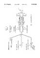
- FIG. 1shows a typical transmitter of a CDMA communication link useful in explaining the operations of the present invention
- FIG. 2shows a simplified block diagram of an illustrative CDMA receiver
- FIG. 3shows a simplified block diagram detail of an illustrative multipath combining CDMA rake receiver
- FIG. 4shows a simplified block diagram of a prior art demodulator "finger" of a rake receiver
- FIG. 5shows a simplified block diagram of an illustrative I-/Q-pilot despreader
- FIG. 6shows a simplified block diagram of a combined demodulator finger where one pilot despreader is shared by the pilot correlator branches and the data correlator branches,
- FIG. 7shows a simplified block diagram of an intermediate design of a first embodiment of the present invention, namely introducing a Walsh switch; this halves the number of additions in the accumulators,
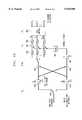
- FIG. 8shows a simplified block diagram of a first embodiment of the present invention, namely Walsh switch and substituting multipliers by squarers
- FIG. 9shows a block diagram of a simplified multiple data correlator arrangement for MC-CDMA.
- FIG. 10shows a block diagram of a second embodiment: an improved multiple data correlator arrangement in accordance with the present invention, namely applying the Walsh switch idea to a MC-CDMA receiver
- the present inventiondescribes a novel single user demodulator structure for coherent pilot code aided synchronous QPSK/CDMA communication links (Quadrature Phase Shift Keying/Code Division Multiple Access).
- An important example of a system using pilot aided QPSK/CDMA in the forward link (base-station to mobile)is described in TIA/EIA/IS-95 (TIA: Telecommunications Industry Associations; EIA: Electronic Industries Association; IS: Interim Standard) which is accepted as a digital cellular phone standard for North America.
- TIA/EIA/IS-95TIA: Telecommunications Industry Associations; EIA: Electronic Industries Association; IS: Interim Standard
- the present inventioneliminates the use of phase correction multipliers used for coherent demodulation.
- the multipliersare substituted by "squarers" which allow for a novel implementation. This turns two-operand operations (multiplications) into one-operand operations (squarings). This is advantageous for implementing the "squarer" as a lookup-table rather and eliminates the multiplications that are performed, e.g., by a Digital Signal Processor (DSP) used for doing the phase correction. Furthermore the number of additions performed in the accumulator part is halved with a corresponding decrease in power dissipation.
- the present inventioncan also be adapted to a Multi-Code CDMA receiver as shown in FIG. 10. In view of increasing importance of wireless services, the present invention is of particular interest for improving implementation-efficiency in handset-designs.
- Shown in FIG. 1is a transmitter for a synchronous pilot code aided CDMA communication link, including the values given for IS-95.
- the outputs of code spreaders 101j and 101kare combined together with a pilot signal in adder 102 to form a Walsh-spread baseband signal.
- the Walsh-spread baseband signalillustratively, at rate R c is multiplied in coders 104-105 by another PN-code spreading sequence, also called short code or pilot code sequence.
- the spreading sequencemay be a periodic binary PN-sequence (PN: Pseudo Noise), different for the I- and Q-channel (QPSK-spreading).
- PNbinary PN-sequence
- QPSK-spreadingQPSK-spreading
- an unmodulated pilot code(Walsh-code 0, always +1, and its data always +1) is embedded in the composite signal as a phase reference for coherent demodulation of the data channels at the receiver.
- One pilot channel for all usersis sufficient since it is a synchronous CDMA link.
- the outputs from coders 104-105are each filtered by FIR filters, 106 and 107, respectively.
- the outputs of the FIR filters 106 and 107are then up-converted by modulators 108 and 109 using radio carrier frequency signals cos( ⁇ c t) and sin( ⁇ c t), respectively.
- the output of modulators 108 and 109are radio frequency signals which are combined in combiner 110 and transmitted via antenna 111 over the air to the mobile user stations.
- This radio frequency QPSK/CDMA signalincludes all channels summed together (data-channels, pilot channel).
- One bit in the baseband (also referred to as symbol) at rate R bconsists of g ⁇ chips ⁇ at rate R c on the channel.
- FIG. 2shows a simplified block diagram of an illustrative CDMA receiver that can be used at a mobile station.
- the radio frequency signals received via antenna 201are down-converted by modulators 202 and 203, using radio frequency signals cos( ⁇ c t) and sin( ⁇ c t), respectively.
- the output of demodulators 202 and 203are each filtered by an anti-aliasing LPF (Low Pass Filter) 204 and 205, respectively to produce a resulting baseband I and Q signals.
- the I and Q signalsare then further decoded and despread by a CDMA RAKE receiver 208 operating under control of Digital Signal Processor (DSP) 209 to produce the output data signal 210.
- the DSPforms a weighted average of each of the data signals received by a different finger, where each finger tracks a different multipath component.
- a RAKE receiveris an (almost) optimum mechanism for receiving signals in a multipath environment.
- FIG. 3shows an illustrative block diagram of a prior art RAKE receiver typically used in a CDMA system.
- a RAKE. receiveris used in both the forward and reverse links of a CDMA system to take advantage of the inherent time diversity in the received signals arriving via different paths of a multipath environment.
- Analog I signals (I) and Q signals (Q)are converted to digital signals by the A/D circuits 301 and 302, respectively.
- Control logic circuit 303provides Digital Signal Processor (DSP) interfacing and control, as well as common timing and control functions for the CDMA receiver.
- DSPDigital Signal Processor
- Control logic circuit 303operates under control of signals received over DSP bus from a DSP, not shown.
- An RSSI (Received Signal Strength Indicator) block 304calculates the total received signal power of the I and Q signals received over the various signal paths.
- each of the finger units 305-308is used to despread/demodulate a received signal arriving over a different air path of the multipath environment. These finger units 305-308 are essentially the same except they have a different time delay, attenuation and phase characteristics.
- the finger unit 308additionally includes a small amount of additional logic to allow its use as a high-speed pilot searcher (for use in coherent receivers to detect the Walsh signal pilot shown in FIG. 1).
- the pilot searcher finger 308examines the incoming signal by continuously correlating it with the pilot PN-sequence. It detects different base-stations and multipath-components and delivers the respective PN-offsets to the demodulator fingers 305-307.
- Each demodulator fingerperforms a coherent demodulation of a certain path of the incoming multipath-distorted signal.
- N pNumber of chips for phase recovery (usually a multiple of N c )
- the real componentis the in-phase component u 1 I , also referred to as I-channel
- the imaginary componentis the quadrature-component u 1 Q , also referred to as Q-channel.
- optimally chosen sampling timesare assumed so one has not to consider pulse shaping or tracking.
- Each fingercontains a pilot on-time correlator for channel estimation and a data on-time correlator for recovering the binary data signal.
- the pilot correlatorconsists of a despreading part 401 and an accumulation part 403, 404.
- the data correlatorconsists of a despreading part 402 and an accumulation part 405, 406.
- the pilot despreader 401is shown in FIG. 5 to function as a I-/Q-pilot despreader: providing complex multiplication, using multipliers 501-504, of the incoming signals u 1 I and u 1 Q with the pilot-PN-spreading sequences p I and p Q .
- the multipliers 501-504are simple negations since the PN-sequence is a random sequence of +1, -1.
- the pilot and Walsh despreader 402 of FIG. 4using multipliers (not shown), despreads the incoming signals u 1 I and u 1 Q using a pilot signal multiplied by a Walsh code sequence.
- the output of the pilot and User k despreader 402gets accumulated over one symbol period (N c chips) to recover the baseband bit data for User k.
- N c chipsthe number of symbols in which there is one output of the pilot correlator and one of the data correlator.
- the phase correction multiplication, in multipliers 407 and 408 at the symbol rate R bprovides a phase corrected signal which can be used --after addition 409--for the binary decision to determine whether a 0 or a 1 was sent (as shown, however, it is outputted to the combiner which coherently combines several concurrently demodulated paths).
- the signalsare ( ⁇ k I .Q is some additional noise which will vanish after the accumulation):
- Walsh-despreadingusing multipliers 604, 605 and accumulators 606, 607, produces the data signals (averaging out of AW k and W k ⁇ k I ,Q): ##EQU5##
- Phase correction(at symbol-rate, also called channel weighting) using multipliers 608 and 609 produce the signals:
- the data output signal u cis exactly the same as for the design in FIG. 4.
- the basic ideais to replace the Walsh-negations, multipliers 604 and 605 of FIG. 6, with Walsh switches 701 and 702 of FIG. 7. As shown in FIG. 7, the result is that accumulators 703-706 perform only half the additions as compared to accumulators 602, 603, 606, and 607 of FIG. 6 (2N c real additions for demodulating a symbol instead of 4N c ).
- the outputs of adder 707being the I component of the pilot correlator, while the output of adder 708 is the I component of the pilot and data correlator.
- the outputs from the accumulators 705 and 706are combined in adders 710 and 711, to produce the signal u B' Q which also can substitute multipliers with squarers.
- the circuit of FIG. 8requires no multipliers (e.g., 608 of FIG. 6) but does require squarers (e.g., 801-802 ) to perform the two squaring operations for the I and Q channels at the symbol rate R b .
- the squarerscan be implemented as a lookup-table (one-operand operation).
- this structuremay be used for non-coherent energy measurement of the pilot channel by leaving the Walsh switch 701 in the +1 position.
- phase estimation branchpilot correlator output
- u 3' Iplus I +minus I
- Multi-Code CDMAwas patented in U.S. Pat. No. 5,442,625 entitled patented by C. -L. I., R. D. Gitlin, "Multi-Code CDMA Wireless Personal Communications Networks" as a packet-based wireless network that accommodates multimedia traffic in any CDMA based system, and as a system that can easily evolve from IS-95 cellular/PCS systems.
- Some improvements of the basic MC-CDMA receiver structureare presented in the previously-identified patent applications.
- the substitution of multipliers by squarers--as shown in FIG. 8 for the conventional IS-95 case--is not possible in a MC-CDMA receiver, but the idea of introducing a Walsh switch (see FIG.
- FIG. 9taken from that application, shows the simplified data correlator part of the enhanced MC-CDMA receiver (also referred to as "Skinny Fat finger”).
- the simplifications in FIG. 9only address the data correlators, whereas the Walsh switch idea of FIG. 10, as will be discussed below, allows the sharing of the data and pilot correlator results.
- the real FWHT (Fast Walsh-Hadamard Transformation) unittakes advantage of using "overlayed" Walsh codes of order M, where M is a power of 2, to produce N correlator outputs (for one user k there are N single CDMA channels to demodulate).
- the complex negator 901multiplies the Base-Walsh-code W(k,0) for user k with the pilot despreader signal which is then summed in accumulator 902.
- the accumulator 902 outputis reset every N C /N input samples and the complex intermediate result is stored in hold-buffers 903. Note that in FIG. 9, 10 thick lines stand for complex signals whereas thin lines represent real signals.
- the demultiplexer or switch 905selects the particular hold-buffer that is to store a particular intermediate result. At the appropriate time (at the end of each symbol) the outputs from the hold-buffers 903 are multiplied by the channel estimate from complex conjugate circuit 909 in multipliers 907. The outputs of multipliers 907 are then converted to real values by the units 906 Re(.) !. The units 906 take only the real part of the complex multiplication results which are then further processed by a real FWHT-block 904 to obtain the real-valued outputs Y O '-Y N- '.
- the channel estimateis obtained from a separate complex correlation (accumulation) which needs N c complex additions.
- Applying the Walsh switch idea to the circuit of FIG. 9results in the circuit of FIG. 10.
- the accumulators 1002 and 1003each perform N c /2N additions and are reset N times per symbol.
- the outputs from the accumulators 1002 and 1003are combined as shown in adders 1004 and 1005.
- the remainder of the circuitoperates in the same manner as previously described for FIG. 9. It should be noted that a channel estimate averaging, which is sometimes desired in a slow fading environment, is still possible with the FIG. 10 structure (inserted in between 908, 909) while maintaining the same savings of addition operations.
Landscapes
- Engineering & Computer Science (AREA)
- Computer Networks & Wireless Communication (AREA)
- Signal Processing (AREA)
- Mobile Radio Communication Systems (AREA)
Abstract
Description
u.sub.1.sup.I =p.sub.k.sup.I (W.sub.k x.sub.l +A) cos φ-p.sub.k.sup.Q (W.sub.k x.sub.l +A) sin φ
u.sub.1.sup.Q =p.sub.k.sup.I (W.sub.k x.sub.l +A) sin φ+p.sub.k.sup.Q (W.sub.k x.sub.l +A) cos φ
u.sub.2.sbsb.k.sup.I =2(x.sub.l W.sub.k +A) cos φ+δ.sub.k.sup.I
u.sub.2.sbsb.k.sup.Q =2(x.sub.l W.sub.k +A) sin φ+δ.sub.k.sup.Q
u.sub.B.sup.I =u.sub.3.sup.I ·u.sub.A.sup.I =4N.sub.p N.sub.c Ax.sub.l cos.sup.2 φ
u.sub.B.sup.Q =u.sub.3.sup.Q ·u.sub.A.sup.Q =4N.sub.p N.sub.c Ax.sub.l sin.sup.2 φ
u.sub.C =u.sub.B.sup.I +u.sub.B.sup.Q =4N.sub.p N.sub.c Ax.sub.l
u.sub.3'.sup.I,Q =u.sub.3.sup.I,Q (N.sub.p =N.sub.c), u.sub.A'.sup.I,Q =u.sub.a.sup.I,Q (N.sub.p =N.sub.c) etc.
u.sub.B'.sup.I =(plus.sup.I +minus.sup.I)·(plus.sup.I -minus.sup.I)=plus .sup.I.spsp.2 -minus.sup.I.spsp.2
u.sub.B'.sup.I =(plus.sup.I).spsp.2-(minus.sup.I).spsp.2=N.sub.c.sup.2 (x.sub.l +A).spsp.2 cos.sup.2 φ-N.sub.c.sup.2 (-x.sub.l +A).spsp.2 cos.sup.2 φ=4N.sub.c.sup.2 Ax.sub.l cos.sup.2 φ
u.sub.B'.sup.Q =. . .=4N.sub.c.sup.2 Ax.sub.l sin.sup.2 φ
u.sub.C =u.sub.B'.sup.I +u.sub.B'.sup.Q =4N.sub.c.sup.2 Ax.sub.l
Claims (10)
Priority Applications (1)
| Application Number | Priority Date | Filing Date | Title |
|---|---|---|---|
| US08/699,008US5910950A (en) | 1996-08-16 | 1996-08-16 | Demodulator phase correction for code division multiple access receiver |
Applications Claiming Priority (1)
| Application Number | Priority Date | Filing Date | Title |
|---|---|---|---|
| US08/699,008US5910950A (en) | 1996-08-16 | 1996-08-16 | Demodulator phase correction for code division multiple access receiver |
Publications (1)
| Publication Number | Publication Date |
|---|---|
| US5910950Atrue US5910950A (en) | 1999-06-08 |
Family
ID=24807554
Family Applications (1)
| Application Number | Title | Priority Date | Filing Date |
|---|---|---|---|
| US08/699,008Expired - LifetimeUS5910950A (en) | 1996-08-16 | 1996-08-16 | Demodulator phase correction for code division multiple access receiver |
Country Status (1)
| Country | Link |
|---|---|
| US (1) | US5910950A (en) |
Cited By (20)
| Publication number | Priority date | Publication date | Assignee | Title |
|---|---|---|---|---|
| US6075811A (en)* | 1997-01-14 | 2000-06-13 | Sony Corporation | Receiving apparatus, receiving method, and terminal unit for use with radio system |
| WO2001039530A1 (en)* | 1999-11-25 | 2001-05-31 | Huawei Technologies Co., Ltd | A method of multi selection coherent detection and device thereof |
| US20010004379A1 (en)* | 1999-12-14 | 2001-06-21 | Alice Wilson | Combiner |
| US6252899B1 (en)* | 1997-04-09 | 2001-06-26 | Yozan Inc. | Complex despreading system |
| US20010030992A1 (en)* | 2000-01-11 | 2001-10-18 | Kim Sung-Jin | Despreading apparatus and method for CDMA signal |
| US6314107B1 (en)* | 1998-10-20 | 2001-11-06 | Qualcomm Incorporated | Method and apparatus for assigning spreading codes |
| WO2002003556A3 (en)* | 2000-07-05 | 2002-08-01 | Ericsson Inc | Method and apparatus for channel gain and channel delay estimation in a multi-carrier cdma system |
| US6449490B1 (en)* | 1999-05-24 | 2002-09-10 | Qualcomm Incorporated | Transmitter directed code division multiple access system using path diversity to equitably maximize throughput |
| DE10108413A1 (en)* | 2001-02-21 | 2002-09-19 | Philips Corp Intellectual Pty | Reception procedure for a mobile phone with multiple code reception and mobile phone |
| US20020136234A1 (en)* | 2001-02-14 | 2002-09-26 | Hakan Eriksson | Tuning the fingers of rake receiver |
| US20020181626A1 (en)* | 2001-04-24 | 2002-12-05 | Lucent Technologies Inc. | Doppler corrected communications receiver and method of removing doppler frequency shift |
| DE10158738A1 (en)* | 2001-11-30 | 2003-07-03 | Systemonic Ag | Method for decoding spread-spectrum coded signals e.g. for communications technology, requires addition of first product from real-input signal and second product from imaginary-part input signal to real-part output signal |
| US20030179737A1 (en)* | 2002-03-25 | 2003-09-25 | Avner Dor | Processing non-pilot channels in a CDMA searcher |
| US20030210735A1 (en)* | 2002-05-07 | 2003-11-13 | Seong-Woo Ahn | System and method for demodulating multiple walsh codes using a chip combiner |
| US20040081113A1 (en)* | 2002-10-18 | 2004-04-29 | Nortel Networks Limited | Orthogonal signaling for CDMA |
| US20070091841A1 (en)* | 1999-05-24 | 2007-04-26 | Qualcomm, Incorporated | Method and System for Scheduling Data Transmission in Communication Systems |
| US20070211766A1 (en)* | 2006-03-08 | 2007-09-13 | Nec Corporation | Multiplex switching |
| US7349421B2 (en) | 2001-08-06 | 2008-03-25 | Qualcomm Incorporated | Method and apparatus for assigning spreading codes |
| CN102315876A (en)* | 2010-07-07 | 2012-01-11 | 电子科技大学 | Timing synchronization processing method based on code assistance |
| US9332429B2 (en) | 2005-06-22 | 2016-05-03 | Odyssey Wireless, Inc. | Systems/methods of adaptively varying a spectral content of communications |
Citations (5)
| Publication number | Priority date | Publication date | Assignee | Title |
|---|---|---|---|---|
| US4397039A (en)* | 1980-12-29 | 1983-08-02 | International Business Machines Corporation | Instantaneous phase tracking in single sideband systems |
| US5325394A (en)* | 1992-06-29 | 1994-06-28 | Motorola, Inc. | Method and apparatus for canceling spread-spectrum noise |
| US5442625A (en)* | 1994-05-13 | 1995-08-15 | At&T Ipm Corp | Code division multiple access system providing variable data rate access to a user |
| US5506865A (en)* | 1992-11-24 | 1996-04-09 | Qualcomm Incorporated | Pilot carrier dot product circuit |
| US5577025A (en)* | 1995-06-30 | 1996-11-19 | Qualcomm Incorporated | Signal acquisition in a multi-user communication system using multiple walsh channels |
- 1996
- 1996-08-16USUS08/699,008patent/US5910950A/ennot_activeExpired - Lifetime
Patent Citations (5)
| Publication number | Priority date | Publication date | Assignee | Title |
|---|---|---|---|---|
| US4397039A (en)* | 1980-12-29 | 1983-08-02 | International Business Machines Corporation | Instantaneous phase tracking in single sideband systems |
| US5325394A (en)* | 1992-06-29 | 1994-06-28 | Motorola, Inc. | Method and apparatus for canceling spread-spectrum noise |
| US5506865A (en)* | 1992-11-24 | 1996-04-09 | Qualcomm Incorporated | Pilot carrier dot product circuit |
| US5442625A (en)* | 1994-05-13 | 1995-08-15 | At&T Ipm Corp | Code division multiple access system providing variable data rate access to a user |
| US5577025A (en)* | 1995-06-30 | 1996-11-19 | Qualcomm Incorporated | Signal acquisition in a multi-user communication system using multiple walsh channels |
Cited By (30)
| Publication number | Priority date | Publication date | Assignee | Title |
|---|---|---|---|---|
| US6075811A (en)* | 1997-01-14 | 2000-06-13 | Sony Corporation | Receiving apparatus, receiving method, and terminal unit for use with radio system |
| US6252899B1 (en)* | 1997-04-09 | 2001-06-26 | Yozan Inc. | Complex despreading system |
| US6314107B1 (en)* | 1998-10-20 | 2001-11-06 | Qualcomm Incorporated | Method and apparatus for assigning spreading codes |
| US8050198B2 (en) | 1999-05-24 | 2011-11-01 | Qualcomm Incorporated | Method and system for scheduling data transmission in communication systems |
| US20070091841A1 (en)* | 1999-05-24 | 2007-04-26 | Qualcomm, Incorporated | Method and System for Scheduling Data Transmission in Communication Systems |
| US6449490B1 (en)* | 1999-05-24 | 2002-09-10 | Qualcomm Incorporated | Transmitter directed code division multiple access system using path diversity to equitably maximize throughput |
| US6907087B1 (en) | 1999-11-25 | 2005-06-14 | Huwei Technologies Co., Ltd. | Method of multi selection coherent detection and device thereof |
| WO2001039530A1 (en)* | 1999-11-25 | 2001-05-31 | Huawei Technologies Co., Ltd | A method of multi selection coherent detection and device thereof |
| US7245652B2 (en)* | 1999-12-14 | 2007-07-17 | Nokia Mobile Phones Limited | Rake combiner for a CDMA rake receiver |
| US20010004379A1 (en)* | 1999-12-14 | 2001-06-21 | Alice Wilson | Combiner |
| US6801568B2 (en)* | 2000-01-11 | 2004-10-05 | Samsung Electronics Co., Ltd. | Despreading apparatus and method for CDMA signal |
| US20010030992A1 (en)* | 2000-01-11 | 2001-10-18 | Kim Sung-Jin | Despreading apparatus and method for CDMA signal |
| WO2002003556A3 (en)* | 2000-07-05 | 2002-08-01 | Ericsson Inc | Method and apparatus for channel gain and channel delay estimation in a multi-carrier cdma system |
| US6876645B1 (en) | 2000-07-05 | 2005-04-05 | Ericsson Inc. | Delay and channel estimation for multi-carrier CDMA system |
| US20020136234A1 (en)* | 2001-02-14 | 2002-09-26 | Hakan Eriksson | Tuning the fingers of rake receiver |
| DE10108413A1 (en)* | 2001-02-21 | 2002-09-19 | Philips Corp Intellectual Pty | Reception procedure for a mobile phone with multiple code reception and mobile phone |
| US20020181626A1 (en)* | 2001-04-24 | 2002-12-05 | Lucent Technologies Inc. | Doppler corrected communications receiver and method of removing doppler frequency shift |
| US7035315B2 (en) | 2001-04-24 | 2006-04-25 | Lucent Technologies Inc. | Doppler corrected communications receiver and method of removing doppler frequency shift |
| US7349421B2 (en) | 2001-08-06 | 2008-03-25 | Qualcomm Incorporated | Method and apparatus for assigning spreading codes |
| DE10158738A1 (en)* | 2001-11-30 | 2003-07-03 | Systemonic Ag | Method for decoding spread-spectrum coded signals e.g. for communications technology, requires addition of first product from real-input signal and second product from imaginary-part input signal to real-part output signal |
| CN100380835C (en)* | 2002-03-25 | 2008-04-09 | 英特尔公司 | Handling pilot and non-pilot channels in CDMA searchers |
| US20030179737A1 (en)* | 2002-03-25 | 2003-09-25 | Avner Dor | Processing non-pilot channels in a CDMA searcher |
| US6987798B2 (en)* | 2002-05-07 | 2006-01-17 | Samsung Electronics Co., Ltd. | System and method for demodulating multiple Walsh codes using a chip combiner |
| US20030210735A1 (en)* | 2002-05-07 | 2003-11-13 | Seong-Woo Ahn | System and method for demodulating multiple walsh codes using a chip combiner |
| US20040081113A1 (en)* | 2002-10-18 | 2004-04-29 | Nortel Networks Limited | Orthogonal signaling for CDMA |
| US9143255B2 (en)* | 2002-10-18 | 2015-09-22 | Microsoft Technology Licensing, Llc | Orthogonal signaling for CDMA |
| US9332429B2 (en) | 2005-06-22 | 2016-05-03 | Odyssey Wireless, Inc. | Systems/methods of adaptively varying a spectral content of communications |
| US20070211766A1 (en)* | 2006-03-08 | 2007-09-13 | Nec Corporation | Multiplex switching |
| US7701840B2 (en)* | 2006-03-08 | 2010-04-20 | Nec Corporation | Multiplex switching |
| CN102315876A (en)* | 2010-07-07 | 2012-01-11 | 电子科技大学 | Timing synchronization processing method based on code assistance |
Similar Documents
| Publication | Publication Date | Title |
|---|---|---|
| US5910950A (en) | Demodulator phase correction for code division multiple access receiver | |
| US5881056A (en) | Method and apparatus of a multi-code code division multiple access receiver having shared accumulator circuits | |
| US5870378A (en) | Method and apparatus of a multi-code code division multiple access receiver having a shared accumulator circuits | |
| US6009089A (en) | Pilot interference cancellation for a coherent wireless code division multiple access receiver | |
| US6529545B2 (en) | Rake receiver | |
| KR100263801B1 (en) | Pilot interference cancellation for a coherent wireless code division multiple access receiver | |
| US6377613B1 (en) | Communication apparatus for code division multiple accessing mobile communications system | |
| JP3376224B2 (en) | Initial synchronization method and receiver in asynchronous cellular system between DS-CDMA base stations | |
| US5737326A (en) | Multi-code code division multiple access receiver | |
| US6459883B2 (en) | Generic finger architecture for spread spectrum applications | |
| JP3003006B2 (en) | Method and apparatus for signal demodulation and diversity combining of quadrature modulated signals | |
| US7310305B2 (en) | Method for determining reference phase in radio communication system which uses orthogonal M-ary modulation, and coherent detection method using the same | |
| KR20000064545A (en) | Parallel Demodulation Method and System for Multiple Chips of CDMA Signal | |
| EP0807345A1 (en) | Data transmission method, transmitter, and receiver | |
| EP1127417A1 (en) | Method of processing cdma signal components | |
| JPH09512691A (en) | Method and receiver for demodulating received signal | |
| US7586980B2 (en) | Apparatus for coherent combining type demodulation in communication system and method thereof | |
| KR100266445B1 (en) | A transmission diversity embodiment method and device for hybrid wideband-cdma as multi-carrier/direct sequence of telecommunication system | |
| JP2778396B2 (en) | Spread spectrum signal receiver | |
| KR100355266B1 (en) | STTD Decoding Demodulator Applicable To Spread Spectrum Communication | |
| JP3806389B2 (en) | Receiver | |
| JPH11127134A (en) | Signal receiver for ds-cdma cellular system | |
| KR20020014147A (en) | Apparatus and method for compensating and presuming of channel in mobile communication system | |
| KR100324042B1 (en) | Baseband Demodulation Unit in Code Division Multiple Access System Receiver with P.N.Despreader Minimizing Quantization Error | |
| EP1580902A1 (en) | Receiver and receiving method |
Legal Events
| Date | Code | Title | Description |
|---|---|---|---|
| AS | Assignment | Owner name:LUCENT TECHNOLOGIES INC., NEW JERSEY Free format text:ASSIGNMENT OF ASSIGNORS INTEREST;ASSIGNOR:BRINK, STEPHEN TEN;REEL/FRAME:008210/0194 Effective date:19960816 | |
| FEPP | Fee payment procedure | Free format text:PAYOR NUMBER ASSIGNED (ORIGINAL EVENT CODE: ASPN); ENTITY STATUS OF PATENT OWNER: LARGE ENTITY | |
| STCF | Information on status: patent grant | Free format text:PATENTED CASE | |
| AS | Assignment | Owner name:CHASE MANHATTAN BANK, AS ADMINISTRATIVE AGENT, THE Free format text:CONDITIONAL ASSIGNMENT OF AND SECURITY INTEREST IN PATENT RIGHTS;ASSIGNOR:AGERE SYSTEMS GUARDIAN CORP. (DE CORPORATION);REEL/FRAME:011667/0148 Effective date:20010402 | |
| AS | Assignment | Owner name:AGERE SYSTEMS GUARDIAN CORP., FLORIDA Free format text:TERMINATION AND RELEASE OF SECURITY INTEREST IN PATENT RIGHTS;ASSIGNOR:JPMORGAN CHASE BANK (F/K/A THE CHASE MANHATTAN BANK);REEL/FRAME:013372/0662 Effective date:20020930 | |
| FPAY | Fee payment | Year of fee payment:4 | |
| REMI | Maintenance fee reminder mailed | ||
| FPAY | Fee payment | Year of fee payment:8 | |
| FPAY | Fee payment | Year of fee payment:12 | |
| AS | Assignment | Owner name:DEUTSCHE BANK AG NEW YORK BRANCH, AS COLLATERAL AG Free format text:PATENT SECURITY AGREEMENT;ASSIGNORS:LSI CORPORATION;AGERE SYSTEMS LLC;REEL/FRAME:032856/0031 Effective date:20140506 | |
| AS | Assignment | Owner name:AVAGO TECHNOLOGIES GENERAL IP (SINGAPORE) PTE. LTD Free format text:ASSIGNMENT OF ASSIGNORS INTEREST;ASSIGNOR:AGERE SYSTEMS LLC;REEL/FRAME:035365/0634 Effective date:20140804 | |
| AS | Assignment | Owner name:AGERE SYSTEMS LLC, PENNSYLVANIA Free format text:TERMINATION AND RELEASE OF SECURITY INTEREST IN PATENT RIGHTS (RELEASES RF 032856-0031);ASSIGNOR:DEUTSCHE BANK AG NEW YORK BRANCH, AS COLLATERAL AGENT;REEL/FRAME:037684/0039 Effective date:20160201 Owner name:LSI CORPORATION, CALIFORNIA Free format text:TERMINATION AND RELEASE OF SECURITY INTEREST IN PATENT RIGHTS (RELEASES RF 032856-0031);ASSIGNOR:DEUTSCHE BANK AG NEW YORK BRANCH, AS COLLATERAL AGENT;REEL/FRAME:037684/0039 Effective date:20160201 | |
| AS | Assignment | Owner name:BANK OF AMERICA, N.A., AS COLLATERAL AGENT, NORTH CAROLINA Free format text:PATENT SECURITY AGREEMENT;ASSIGNOR:AVAGO TECHNOLOGIES GENERAL IP (SINGAPORE) PTE. LTD.;REEL/FRAME:037808/0001 Effective date:20160201 Owner name:BANK OF AMERICA, N.A., AS COLLATERAL AGENT, NORTH Free format text:PATENT SECURITY AGREEMENT;ASSIGNOR:AVAGO TECHNOLOGIES GENERAL IP (SINGAPORE) PTE. LTD.;REEL/FRAME:037808/0001 Effective date:20160201 | |
| AS | Assignment | Owner name:AVAGO TECHNOLOGIES GENERAL IP (SINGAPORE) PTE. LTD., SINGAPORE Free format text:TERMINATION AND RELEASE OF SECURITY INTEREST IN PATENTS;ASSIGNOR:BANK OF AMERICA, N.A., AS COLLATERAL AGENT;REEL/FRAME:041710/0001 Effective date:20170119 Owner name:AVAGO TECHNOLOGIES GENERAL IP (SINGAPORE) PTE. LTD Free format text:TERMINATION AND RELEASE OF SECURITY INTEREST IN PATENTS;ASSIGNOR:BANK OF AMERICA, N.A., AS COLLATERAL AGENT;REEL/FRAME:041710/0001 Effective date:20170119 |