US5910944A - Radio telephone and method for operating a radiotelephone in slotted paging mode - Google Patents
Radio telephone and method for operating a radiotelephone in slotted paging modeDownload PDFInfo
- Publication number
- US5910944A US5910944AUS08/808,555US80855597AUS5910944AUS 5910944 AUS5910944 AUS 5910944AUS 80855597 AUS80855597 AUS 80855597AUS 5910944 AUS5910944 AUS 5910944A
- Authority
- US
- United States
- Prior art keywords
- radiotelephone
- time
- sleep
- timing
- recited
- Prior art date
- Legal status (The legal status is an assumption and is not a legal conclusion. Google has not performed a legal analysis and makes no representation as to the accuracy of the status listed.)
- Expired - Lifetime
Links
- 238000000034methodMethods0.000titleclaimsdescription38
- 238000004891communicationMethods0.000claimsabstractdescription17
- 230000004044responseEffects0.000claimsdescription14
- 230000002618waking effectEffects0.000claimsdescription3
- 230000003213activating effectEffects0.000claims5
- 230000000415inactivating effectEffects0.000claims3
- 230000001360synchronised effectEffects0.000abstractdescription8
- 238000010586diagramMethods0.000description9
- 230000004622sleep timeEffects0.000description9
- 230000008569processEffects0.000description7
- 230000000630rising effectEffects0.000description7
- 238000012545processingMethods0.000description4
- 230000001413cellular effectEffects0.000description3
- 238000012544monitoring processMethods0.000description3
- 230000004617sleep durationEffects0.000description3
- 238000001228spectrumMethods0.000description3
- 230000005540biological transmissionEffects0.000description2
- 238000005259measurementMethods0.000description2
- 238000012986modificationMethods0.000description2
- 230000004048modificationEffects0.000description2
- 230000009471actionEffects0.000description1
- 230000008859changeEffects0.000description1
- 238000006243chemical reactionMethods0.000description1
- 238000012937correctionMethods0.000description1
- 230000006870functionEffects0.000description1
- 238000007685laparoscopic sleeve gastrectomyMethods0.000description1
- 230000007246mechanismEffects0.000description1
- 238000005096rolling processMethods0.000description1
Images


Classifications
- H—ELECTRICITY
- H04—ELECTRIC COMMUNICATION TECHNIQUE
- H04B—TRANSMISSION
- H04B1/00—Details of transmission systems, not covered by a single one of groups H04B3/00 - H04B13/00; Details of transmission systems not characterised by the medium used for transmission
- H04B1/69—Spread spectrum techniques
- H04B1/707—Spread spectrum techniques using direct sequence modulation
- H04B1/7073—Synchronisation aspects
- H04B1/7075—Synchronisation aspects with code phase acquisition
- H04B1/70756—Jumping within the code, i.e. masking or slewing
- H—ELECTRICITY
- H04—ELECTRIC COMMUNICATION TECHNIQUE
- H04W—WIRELESS COMMUNICATION NETWORKS
- H04W52/00—Power management, e.g. Transmission Power Control [TPC] or power classes
- H04W52/02—Power saving arrangements
- H—ELECTRICITY
- H04—ELECTRIC COMMUNICATION TECHNIQUE
- H04B—TRANSMISSION
- H04B1/00—Details of transmission systems, not covered by a single one of groups H04B3/00 - H04B13/00; Details of transmission systems not characterised by the medium used for transmission
- H04B1/06—Receivers
- H04B1/16—Circuits
- H—ELECTRICITY
- H04—ELECTRIC COMMUNICATION TECHNIQUE
- H04W—WIRELESS COMMUNICATION NETWORKS
- H04W52/00—Power management, e.g. Transmission Power Control [TPC] or power classes
- H04W52/02—Power saving arrangements
- H04W52/0209—Power saving arrangements in terminal devices
- H04W52/0212—Power saving arrangements in terminal devices managed by the network, e.g. network or access point is leader and terminal is follower
- H04W52/0216—Power saving arrangements in terminal devices managed by the network, e.g. network or access point is leader and terminal is follower using a pre-established activity schedule, e.g. traffic indication frame
- H—ELECTRICITY
- H04—ELECTRIC COMMUNICATION TECHNIQUE
- H04B—TRANSMISSION
- H04B2201/00—Indexing scheme relating to details of transmission systems not covered by a single group of H04B3/00 - H04B13/00
- H04B2201/69—Orthogonal indexing scheme relating to spread spectrum techniques in general
- H04B2201/707—Orthogonal indexing scheme relating to spread spectrum techniques in general relating to direct sequence modulation
- H04B2201/70701—Orthogonal indexing scheme relating to spread spectrum techniques in general relating to direct sequence modulation featuring pilot assisted reception
- H—ELECTRICITY
- H04—ELECTRIC COMMUNICATION TECHNIQUE
- H04B—TRANSMISSION
- H04B2201/00—Indexing scheme relating to details of transmission systems not covered by a single group of H04B3/00 - H04B13/00
- H04B2201/69—Orthogonal indexing scheme relating to spread spectrum techniques in general
- H04B2201/707—Orthogonal indexing scheme relating to spread spectrum techniques in general relating to direct sequence modulation
- H04B2201/70707—Efficiency-related aspects
- H04B2201/70709—Efficiency-related aspects with discontinuous detection
- H—ELECTRICITY
- H04—ELECTRIC COMMUNICATION TECHNIQUE
- H04W—WIRELESS COMMUNICATION NETWORKS
- H04W52/00—Power management, e.g. Transmission Power Control [TPC] or power classes
- H04W52/02—Power saving arrangements
- H04W52/0209—Power saving arrangements in terminal devices
- H04W52/0251—Power saving arrangements in terminal devices using monitoring of local events, e.g. events related to user activity
- H04W52/0258—Power saving arrangements in terminal devices using monitoring of local events, e.g. events related to user activity controlling an operation mode according to history or models of usage information, e.g. activity schedule or time of day
- Y—GENERAL TAGGING OF NEW TECHNOLOGICAL DEVELOPMENTS; GENERAL TAGGING OF CROSS-SECTIONAL TECHNOLOGIES SPANNING OVER SEVERAL SECTIONS OF THE IPC; TECHNICAL SUBJECTS COVERED BY FORMER USPC CROSS-REFERENCE ART COLLECTIONS [XRACs] AND DIGESTS
- Y02—TECHNOLOGIES OR APPLICATIONS FOR MITIGATION OR ADAPTATION AGAINST CLIMATE CHANGE
- Y02D—CLIMATE CHANGE MITIGATION TECHNOLOGIES IN INFORMATION AND COMMUNICATION TECHNOLOGIES [ICT], I.E. INFORMATION AND COMMUNICATION TECHNOLOGIES AIMING AT THE REDUCTION OF THEIR OWN ENERGY USE
- Y02D30/00—Reducing energy consumption in communication networks
- Y02D30/70—Reducing energy consumption in communication networks in wireless communication networks
Definitions
- the present inventiongenerally relates to reducing power consumption in portable radios such as radiotelephones. More particularly, the present invention relates to a method for operating a radiotelephone in slotted paging mode in a Code Division Multiple Access (CDMA) radiotelephone system.
- CDMACode Division Multiple Access
- Slotted paging modeis a form of discontinuous reception (DRX) operation for a battery-operated mobile radio such as a cellular radiotelephone.
- the mobile radiois configured for radio communication with one or more remote base stations in a radiotelephone system.
- DRXdiscontinuous reception
- the radiotelephonewhen the radiotelephone (also referred to as a mobile station) is in an idle mode (i.e., not engaged in a call), the radiotelephone does not continuously monitor a paging channel but generally remains in a low power state.
- Slotted paging modeis critical to the life of the battery of the radiotelephone.
- the goal of slotted mode operationis to reduce the on time of the radio to a minimum and to power down as much of the radio as possible during sleep periods.
- the radiotelephonewakes up only during slots preassigned by the radiotelephone system or to process some other condition, such as a user input.
- the radioWhen recovering from a sleep period, the radio must reacquire a radio frequency (RF) link with a base station in the radiotelephone system.
- Link acquisition and other operations including communication protocols for such a systemare defined in an air interface specification.
- IS-95defines a direct sequence code division multiple access (DS-CDMA or CDMA) radiotelephone system.
- a radiotelephone in a CDMA systemmust be synchronized with system time, which is the timing maintained by base stations and a network controller in the CDMA system. Timing for the forward link (base station to mobile station) must be maintained by the radiotelephone with the expectation that, when an assigned slot occurs, the radio can wake up quickly, make corrections for timing uncertainties and be ready to acquire and process the paging channel.
- Synchronization with the forward linkinvolves alignment of locally generated pseudorandom noise (PN) sequences with PN sequences transmitted by a base station on a pilot channel.
- the transmitted sequencesinclude a "short PN” sequence which repeats every 262/3 ms and a "long PN” sequence which repeats once every 41 days.
- the radiotelephonecontains sequence generators which generate short PN and long PN sequences identical to those used by the base station.
- the radiotelephoneuses a searcher receiver or other mechanism for aligning the short PN sequence with those received from a base station. Once the pilot channel has been acquired, the radiotelephone acquires a synchronization channel and a paging channel. The radiotelephone can then correctly demodulate traffic channels and establish a full duplex link with the base station.
- the radiotelephoneWhen waking up after a sleep time, the radiotelephone must synchronize with the long PN sequence and short PN sequence. Both the short PN sequence and the frame boundary repeat with reasonable frequency in an IS-95 system. Frame boundaries occur on every third PN roll boundary. A PN roll boundary is defined as the short PN sequence rolling back to its initial value.
- LSGlinear sequence generator
- LSGsare described by polynomials and implemented using shift registers and exclusive-or gates. Since the short PN sequence repeats only every 262/3 ms, when exiting sleep the LSG can be conveniently stopped at a particular phase in the sequence until the phase correlates with the system PN. The short PN LSG is then restarted, in synchronization with system timing.
- the long PN sequencerepeats only every 41 days. It is impractical to stop the long PN generator of the radiotelephone (for example, when it is time to sleep), then rapidly clock it to catch up with the system's long PN when it is time to wake up.
- acquiring the PN sequencesrequires that an accurate time reference be kept at the mobile station during sleep mode.
- the appropriate PN sequencescan be determined for correlation with the system PN sequences upon exit from sleep mode.
- maintaining a highly accurate timing referencerequires relatively high power dissipation, which is inconsistent with a low power sleep mode.
- the radiotelephonemay also be required to wake up to process or respond to other events occurring asynchronously in the radio.
- an eventis a user input, such as a keypress of the keypad of the radiotelephone. Response to such an input should be rapid, with no perceptible delay for the user.
- FIG. 1is a block diagram of a radiotelephone system
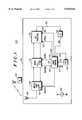
- FIG. 2is a block diagram of a portion of the radiotelephone of FIG. 1;
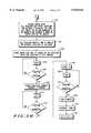
- FIG. 3A and FIG. 3Bare a flow diagram illustrating operation of the radiotelephone of FIG. 1;
- FIG. 4A and FIG. 4Bare a timing diagram for the radiotelephone of FIG. 1;
- FIG. 5is a flow diagram illustrating operation of the radiotelephone of FIG. 1.
- a radiotelephone system 100includes a plurality of base stations such as base station 102 configured for radio communication with one or more mobile stations including a Code Division Multiple Access (CDMA) radiotelephone such as radiotelephone 104.
- the radiotelephone 104is configured to receive and transmit direct sequence code division multiple access (DS-CDMA) signals to communicate with the plurality of base stations, including base station 102.
- the radiotelephone system 100is a CDMA radiotelephone system operating according to TIA/EIA Interim Standard IS-95, "Mobile Station-Base Station Compatibility Standard for Dual-Mode Wideband Spread Spectrum Cellular System," operating at 800 MHz.
- the radiotelephone system 100could operate in accordance with other CDMA systems including PCS systems at 1800 MHz or with any other suitable digital radiotelephone systems.
- the base station 102transmits spread spectrum signals to the radiotelephone 104.
- the symbols on the traffic channelare spread using a Walsh code in a process known as Walsh covering.
- Each mobile station such as the radiotelephone 104is assigned a unique Walsh code by the base station 102 so that the traffic channel transmission to each mobile station is orthogonal to traffic channel transmissions to every other mobile station.
- the symbolsare spread using a short PN sequence or code, which repeats every 262/3 ms and a long PN sequence or code, which repeats every 41 days.
- Communication on the radio frequency (RF) link between a base station and the radiotelephone 104is in the form of chips at a chip rate of 1.2288 Mega-chips per second. A chip is a data bit.
- the radiotelephone 104includes an antenna 106, an analog front end 108, a modem 110, a call processor 112, a timing controller 114, an oscillator 116, a user interface 118 and a battery 150.
- the battery 150provides operating power to the other components of the radiotelephone 104.
- the antenna 106receives RF signals from the base station 102 and from other base stations in the vicinity. Received RF signals are converted to electrical signals by the antenna 106 and provided to the analog front end 108.
- the analog front endincludes an RF portion 109 including circuitry such as a receiver and transmitter which may be powered down in slotted paging mode.
- the analog front end 108filters the signals and provides conversion to baseband signals.
- the analog baseband signalsare provided to the modem 110, which converts them to streams of digital data for further processing.
- the modem 110generally includes a rake receiver and a searcher receiver.
- the searcher receiverdetects pilot signals received by the radiotelephone 104 from the plurality of base stations including the base station 102.
- the searcher receiverdespreads pilot signals using a correlator with system PN codes generated in the radiotelephone 104 using local reference timing.
- the searcher receiverincludes one or more sequence generators such as linear sequence generator (LSG) 120 for generating the PN codes.
- LSGlinear sequence generator
- the modem 110correlates the locally generated PN codes with the received CDMA signals.
- the modem 110detects system timing indicators transmitted by the radiotelephone system 100.
- the modem 110detects PN rollover boundaries in the CDMA signal and provides an indication of the PN rollover boundaries to the timing controller 114.
- the modemalso includes circuitry for transmitting data from the radiotelephone 104 to base stations such as base station 102.
- the modem 110may be constructed from conventional elements.
- the call processor 112controls the functions of the radiotelephone 104.
- the call processor 112operates in response to stored programs of instructions and includes a memory for storing these instructions and other data.
- the call processor 112has a clock input 122 for receiving a clock signal and an interrupt input 124 coupled to the timing controller 114 for receiving interrupt request signals.
- the call processor 112receives from the base station 102 the interval on which the radiotelephone must look for pages. Over this interval, the radiotelephone monitors the paging channel for up to 160 ms and can sleep the remainder of the time.
- the call processor 112coordinates the events in the radiotelephone 104 required for entry into and exit from sleep mode.
- Such eventsinclude keeping track of system time, advancing LSG states, restarting the oscillator 116, enabling power to the RF portion 109 in the analog front end 108, and restarting the clock from the timing controller 114 to the modem 110.
- the call processor 112is coupled to other elements of the radiotelephone 104. Such connections are not shown in FIG. 1 so as to not unduly complicate the drawing figure.
- the user interface 118permits user control of the operation of the radiotelephone 104.
- the user interface 118typically includes a display, a keypad, a microphone and an earpiece.
- the user interface 118is coupled to the call processor 112 by a bus 152.
- the timing controller 114controls timing of the radiotelephone 104.
- the timing controller 114controls entry to and exit from slotted paging mode by the radiotelephone 104 and synchronization of local timing of the radiotelephone 104 and system timing of the radiotelephone system 100.
- the timing controller 114has a clock input 130 for receiving a clock signal from the oscillator 116, an interrupt input 131 for receiving interrupt requests from the user interface 118, and an interrupt input 132 for receiving interrupt requests from other components of the radiotelephone 104.
- the timing controller 114has a timing input 134 for receiving timing signals from the modem 110 and a timing output 136 for providing timing signals to the modem 110.
- the timing signals (labeled PNSTROBE in FIG. 1) received from the modem 110correspond to PN roll boundaries of the radiotelephone's short PN sequence synchronized to the base station.
- a PN roll boundaryis defined as the return of the short PN sequence to its initial value.
- the PNSTROBEis a series of pulses every 262/3 ms synchronized to the PN roll boundary.
- the timing signals (labelled CHIPX8 in FIG. 1) provided to the modem 110are clock signals at a rate eight times the chip rate, or 8 ⁇ 1.2288 Mega-chips per second. Other suitable rates may be used. When this timing signal is removed from the modem 110, the modem 110 enters a low power mode and all internal states are frozen.
- the oscillator 116is a reference oscillator for generating a reference clock signal at a first rate.
- the oscillator 116is a fine resolution clock which produces a highly accurate, fine resolution clock signal such as a 16.8 MHz clock signal.
- the timing controller 114has a control output 138 for providing a control signal to the oscillator 116. In response to the control signal, the oscillator 116 is selectively activated and inactivated. When inactivated, the oscillator enters a low power mode.
- the timing controller 114further provides a control signal (labelled RXCTRLB in FIG. 1) to the analog front end 108. In response to this control signal, a portion of the analog front end 108 is selectively powered down.
- a sleep time controller 200 of the timing controller 114includes a clock edge synchronizer 202, a programmable divider 203, a sleep clock generator 205, a reference timer 204, a reference latch 206, an offset latch 208, a sleep timer 210, a sleep latch 212, a comparator 214, registers 216, and select logic 218.
- the sleep time controller 200places the radiotelephone 104 in a low power sleep mode having a duration based on the timing accuracy of the sleep clock generator 205. In the sleep mode, the sleep time controller 200 simulates system timing until end of the sleep duration determined by the call processor 112 (FIG. 1).
- the call processor 112determines timing of one or more events for reactivating the radiotelephone 104 from sleep mode.
- the call processorcalculates an enable oscillator time for restarting the oscillator 116, a warmup time for reactivating a portion of the RF portion 109 of the analog front end 108, and a pre-wake time for restarting a reference timer used for obtaining fine timing resolution necessary for restarting the CHIPX8 clock signal to the modem.
- the sleep clock generator 205generates a sleep clock signal.
- the sleep clock generator 205is a coarse resolution clock which generates a coarse resolution clock signal, the sleep clock signal.
- the sleep clock generator 205produces the sleep clock signal at a second clock rate which is different from the first clock rate of the oscillator 116.
- the sleep clock signalis a 32 KHz signal, but any suitable frequency may be used.
- the programmable dividerdivides the sleep clock frequency by, for example, powers of 2 in the range 1, 2, 4, . . . 128.
- the clock edge synchronizer 202has a fast clock input 220 for receiving a highly accurate clock signal from the oscillator 116 (FIG. 1), a sleep clock input 222 for receiving the sleep clock signal which has been divided down by the programmable divider 203, and a PN roll input 223 for receiving the PNSTROBE signal from the modem 110 (FIG. 1).
- the clock edge synchronizer 202provides two clock signals. At a first output 224, the clock edge synchronizer 202 provides a sleep clock signal. In the illustrated embodiment, the sleep clock signal is a low speed, coarse resolution clock signal, having a rate of 32 KHz divided by the programmable divider 203. At a second output 226, the clock edge synchronizer 202 provides a reference clock signal. In the illustrated embodiment, the reference clock signal is a high speed (e.g., 16.8 MHz), fine resolution clock signal. The reference clock signal is turned off during sleep mode to conserve battery power in the radiotelephone. The clock edge synchronizer 202 synchronizes the various asynchronous clock edges to provide appropriate clock and latching signals.
- the timing controller 114places a portion of the CDMA radiotelephone 104, including the oscillator 116, in a low power sleep mode.
- the timing controller 114times a duration of the low power sleep mode utilizing the coarse resolution clock signal.
- the clock edge synchronizer 202synchronizes timing of the CDMA radiotelephone to system timing of the CDMA radiotelephone system using the fine resolution clock signal.
- the clock edge synchronizer 202removes the CDMA radiotelephone from the low power sleep mode substantially synchronized with system timing.
- the timing controller 114measures duration of one or more of the coarse resolution clock or sleep clock periods using the fine resolution clock signal from the oscillator 116. This is done by counting the number of complete reference clock periods which occur over an integer number of sleep clock periods.
- the radiotelephone 104enters a low power sleep mode for a time duration that is based on sleep clock periods.
- the measurement of the sleep clock periodcan be improved by counting a larger number of sleep clock signal periods and reference clock signal periods. The better the measurement accuracy, the longer the time duration of the sleep mode may be extended while still permitting exit from the sleep mode substantially synchronously with a PN roll boundary.
- the call processor 112keeps track of PN roll boundaries, too, and uses them to know what the system time is.
- the call processorIn order to know the values of the sleep timer 210 and the reference timer 204 at a future action time, the call processor must have four pieces of information. The first is the duration of the one sleep clock period. The second is the system time at the last PN roll boundary. The third is the contents of the sleep timer 210 at the time of the last PN roll boundary. The fourth is the difference between occurrence of the PN roll boundary and the next rising edge of the sleep clock signal. This fourth piece of information is necessary to provide the fine timing necessary to resolve time to an accuracy of a period of the reference clock. To provide this information, the sleep timer 210 counts periods of the sleep clock signal and the reference timer 204 counts periods of the reference clock signal.
- the sleep latch 212is coupled to the sleep timer 210 for storing contents of the sleep timer 210 at a first predetermined time.
- the current value of the sleep timer 210is stored in the sleep latch 212.
- the valueis latched just after the rising edge of the sleep clock signal following a PN roll boundary indicated by the PNSTROBE signal at the input 223. This value is used by the call processor 112 to compute wakeup times by storing a copy of the system time.
- the sleep timer 210 and the sleep latch 212are both 16 bits wide.
- the reference latch 206is coupled to the reference timer 204 for storing contents of the reference timer 204 at the first predetermined time or any suitable time.
- the current value of the reference timer 204is stored in the reference latch 206 just after each rising edge of the sleep clock signal following a PN roll boundary indicated by the PNSTROBE signal at the input 223.
- the reference latch 206counts the number of reference clock periods that occur over the number of sleep clock periods indicated by the value stored in the sleep latch 212.
- the reference timer 204 and the reference latch 206are both 24 bits wide.
- the offset latch 208is coupled to the reference timer 204 for storing the contents of the reference timer 204 at a second predetermined time.
- the valueis latched immediately after a PN roll boundary indicated by the PN strobe signal at the input 223.
- the current value of the reference timer 204is stored in the offset latch 208 just after the first rising edge of the sleep clock signal following a PN roll boundary indicated by the PNSTROBE signal at the input 223.
- the value stored in the offset latch 208is subtracted from the contents of the reference latch 206 to yield the time since the last PN roll boundary.
- the offset latchstores a time from a last received system timing reference to the first predetermined time.
- the offset latchis 24 bits wide.
- the comparator 214compares the contents of the sleep timer 210 and the contents of one of the registers 216.
- the comparator 214provides a match signal to the select logic 218.
- the registers 216store data corresponding to one or more predetermined event times, the predetermined event times corresponding to wake up events.
- a first register 230stores an enable oscillator time corresponding to a sleep count at which the oscillator 116 is to be enabled.
- a second register 232stores a warmup time corresponding to a sleep timer count when a portion of the analog front end 108.
- a third register 234stores a pre-wake time corresponding to a sleep clock count when the reference timer 204 is to be reactivated.
- FIG. 3A and FIG. 3Bare a flow diagram illustrating operation of the radiotelephone 104 of FIG. 1 for entering and exiting slotted paging mode.
- FIG. 3A and 3Bwill be described in conjunction with FIG. 4A and FIG. 4B, which is a timing diagram illustrating timing relationships of signals in the radiotelephone 104 operated in accordance with the present invention.
- the methodbegins at step 302.
- the radiotelephone 104receives a CDMA signal from a base station and monitors the paging channel for pages directed by a base station such as base station 102 to the radiotelephone 104.
- the clock edge synchronizer 202provides the sleep clock signal 402 at a predetermined frequency, such as 32 KHz, the sleep timer 210 is off 404 and the sleep latch 212 does not contain a valid value 406.
- the CHIPX8 clockis active, point 408, 410, RF portion 109 of the analog front end 108 are powered on, point 412, and the oscillator 116 is powered on, point 414.
- the base station 102informs the radiotelephone 104 of the time interval at which the radiotelephone 104 should wake up and look for pages.
- the radiotelephoneenters slotted mode.
- the call processor 112enables the slotted mode logic of the sleep time controller 200.
- the radiotelephone 104resets the sleep timer 210 and the reference timer 204 and begins monitoring its assigned slot.
- the sleep timer 210begins counting the number of edges of the sleep clock signal 402. In FIG. 4A and FIG. 4B, the number shown adjacent to the sleep timer edges corresponds to the contents of the sleep timer 210, starting at the reset value 0 and incrementing by one with each rising edge of the sleep clock signal 402.
- the reference clock signal and reference timer 204operate in similar fashion.
- a system timing indicatorsuch as a PN roll boundary 420 is detected.
- the PN roll boundary 420 and subsequent PN roll boundariescorrespond to the PN roll boundaries of system timing.
- Other system timing indicatorsmay be used, but the PN roll boundaries are well suited because they occur with precise regularity at short period (262/3 ms).
- the current value of the reference timer 204is latched into the offset latch 208 at point 420.
- the first rising edge following the PN roll boundarycauses the sleep timer value to be latched into the sleep latch 212 and the reference timer value to be latched into the reference latch 206.
- the radiotelephone 104operates in a loop including step 314 and step 316 while monitoring the paging channel until, at step 316, the radiotelephone 104 is ready to go to sleep.
- the call processor 112determines that it is time for the radiotelephone 104 to go to sleep.
- the call processor 112disables the reference timer 204 and the modem 110.
- the RF portion 109 of the analog front end 108is also powered down, point 432.
- the sleep timer 210remains active.
- the call processor 112reads the value of the sleep latch 212.
- the call processor 112also reads the values in the offset latch 208 and in the reference timer 204. These values yield the time of the previous PN roll boundary 424.
- the call processor 112determines a wakeup time.
- the call processor 112calculates one or more wakeup times for exiting the sleep mode.
- the call processor 112computes the times the timing controller 200 should wake up different parts of the radio and writes data corresponding to those times to the registers 216.
- the CHIPX8 clock to the modem 110is disabled.
- the call processor 112uses the contents of the sleep timer 210, the reference timer 204 and the offset latch 208 to calculate the time from the last PN roll boundary. Also, the call processor 112 advances the LSG 120 of the modem 110 ahead to the time when the CHIPX8 clock will be restarted.
- the call processor 112computes the time to turn on the oscillator 116, the RF portion 109 of the analog front end 108 and the modem 110.
- the call processor 112performs timer computations as follows:
- wake -- timesystem time at which the modem 110 will wake up and attempt to reacquire the system.
- latched -- pn -- timesystem time of the PN roll on which the contents of the two timers was latched prior to going to sleep.
- osc -- warm -- timethe amount of time the oscillator 116 needs to be on before the output is locked and stable.
- RF -- warm -- timethe amount of time the RF portion 109 of the analog front end 108 needs to be on before providing useful output.
- f sleepf ref * (sleep latch value/reference latch value).
- t offsetoffset latch value * f ref .
- REFTIMER(2 23 -1)-Truncate (f ref * (wake -- time-(pre-wake time/f sleep )))!.
- PREWAKETIMETruncate (wake -- time-(latched pn -- time+t offset )) * f sleep !.
- WARMUPTIMEPREWAKETIME-Truncate RF -- warm -- time * f sleep !.
- ENOSCTIMEWARMUPTIME-Truncate osc -- warm -- time * f sleep )!
- ENOSCTIMEM+A
- WARMUPTIMEM+B
- PREWAKETIMEM+C
- the radiotelephone 104enters a low power sleep mode.
- the oscillator 116is powered down by removing power to the oscillator 116, point 428.
- the CHIPX8 clock signal from the timing controller 114 to the modem 110is stopped, point 430.
- step 328any other suitable portions of the radiotelephone 104 are shut down, consistent with the goal of slotted mode operation of reducing the on time of the radiotelephone 104 to a minimum and of powering down as much of the radiotelephone 104 as possible during sleep periods.
- the sleep time controller 200times a sleep duration using a coarse resolution clock. During sleep mode, timing is performed by the sleep timer 210 in response to the sleep clock signal. Thus, in the sleep mode, the sleep time controller 200 simulates system timing until end of the sleep duration defined by the events stored in the registers 216. While the radiotelephone 104 is asleep, it does not receive any PN roll information in the form of PN roll boundaries, point 434, since the RF portion 109 of the analog front end 108 and the modem 110 are powered down.
- the contents of the sleep timer 210 and the contents of the first register 230are provided to the comparator 214, step 329.
- the methodremains in a loop including step 328 and step 329.
- the contents of the sleep timer 210equals the contents of the first register 230 (ENOSCTIME)
- a match signalis provided to an input 250 of the select logic 218.
- the select logic 218provides a signal (labelled ENOSC in FIG. 2) to restart the oscillator 116, point 436.
- the radiotelephone 104continues in sleep mode, step 332.
- the contents of the sleep timer 210 and the contents of the second register 232are compared in the comparator 214, step 334.
- the methodremains in the loop including step 332 and step 334.
- the value in the sleep timer 210equals WARMUPTIME
- a signalis asserted to cause clocking signals to be provided to the input 122 of the call processor 112 (FIG. 1) and, at step 336, to turn on the RF portion 109 of the analog front end 108, point 438.
- the radiotelephone 104continues in sleep mode, step 338.
- the contents of the sleep timer 210 and the contents of the third register 234are compared in the comparator 214, step 340.
- the methodremains in the loop including step 338 and step 340.
- a pre-wake signalis asserted by the select logic 218. This indicates the time that the radiotelephone 104 expects to receive its slotted paging mode data.
- the pre-wake signalis provided to the clock edge synchronizer 202, re-enabling the reference clock signal and starting the reference timer 204. This is synchronized to system timing by synchronizing to a received PN roll boundary 440 received at the PNSTROBE input 223.
- the reference timer 204is needed to get the fine resolution necessary to restart the CHIPX8 clock.
- the reference timer 204receives the reference clock signal and counts down the time between the pre-wake time and the wakeup time. When the reference timer 204 rolls over, indicating the wakeup time, the reference timer 204 provides a signal (labelled REFROLL in FIG. 2) to the select logic 218. In response to this signal, the select logic 218 provides a signal to the modem such as CHIPX8. The signal is provided substantially synchronized with a received PN roll boundary.
- the sleep time controller 200synchronized timing of the radiotelephone 104 to system timing using a fine resolution clock, the reference clock signal provided to the reference timer 204.
- the CHIPX8 clock signalis provided to the modem, step 342. Since the PN code sequence generators for the short PN sequence and the long PN sequence, LSG 120, have been previously moved forward, the modem 110 can search over a narrow window of time uncertainty in order to reacquire the system and begin decoding the paging channel.
- the radiotelephonereceives its paging information during its assigned paging slot, step 344, then repeats the method, step 346.
- FIG. 5shows a flow diagram for a method in accordance with the present invention of processing non-sleep related interrupts in the radiotelephone of FIG. 1 during slotted paging mode operation.
- step 502interrupts are detected and processed at any of step 306, step 328 or step 332 of FIG. 3A and FIG. 3B.
- the timing controller 114(FIG. 1) is configured to receive interrupt signals at the interrupt input 132. At step 504, an interrupt signal is received at the interrupt input 132. In response to the interrupt signal, the timing controller 114 activates the call processor 112, for example, by providing clock signals to the input 122 and an interrupt request to the interrupt input 124, to handle the interrupt.
- the call processor 112determines if the radiotelephone needs to wake up to process the interrupt.
- the radiotelephone 104will have to wake up to process an interrupt, for example that requires the radiotelephone 104 to originate a call or change operational modes. If the radiotelephone does not need to wake up, at step 510 the call processor 112 executes the necessary operations and clears the interrupt request received at the interrupt input 124, step 510.
- the call processor 112is de-activated, returning to the low-power sleep mode.
- the methodcontinues with regular slotted mode operation described above in conjunction with FIG. 3A and FIG. 3B.
- the call processor 112determines a point in the future at which the modem 110 will begin monitoring the channel.
- the call processor 112programs the sleep timer 210 and the reference timer 204 to wake up the radiotelephone 104 at this new time.
- the call processorprograms the LSG 120 in the modem 110 to correspond to the same point in time.
- the radiotelephone 104continues processing sleep mode as illustrated in FIG. 3A and FIG. 3B, but using the time values and the PN roll boundary determined in step 516 and step 518.
- the present inventionprovides a radiotelephone and a method for operating a radiotelephone in slotted paging mode.
- the radiotelephonePrior to entering a low power sleep state, calculates the time to wake up and other intermediate times corresponding to wake up events. These include the time to restart an oscillator, the time to activate RF circuitry and the time to start clocking a modem. Also, before entering sleep, the radiotelephone determines the linear sequence generator state required at the wake up time and advances the LSG in the modem ahead to that value.
- a sleep timersimulates system timing to provide an indication when to exit sleep mode. Duration of the sleep mode is timed using a coarse resolution clock signal.
- the radiotelephone and methodprovide for immediate processing of non-sleep related interrupts.
- the radiotelephonereduces its on time in slotted paging mode to the absolute minimum and powers down as much of the radiotelephone as possible during sleep periods.
Landscapes
- Engineering & Computer Science (AREA)
- Computer Networks & Wireless Communication (AREA)
- Signal Processing (AREA)
- Mobile Radio Communication Systems (AREA)
- Transceivers (AREA)
Abstract
Description
Claims (17)
Priority Applications (8)
| Application Number | Priority Date | Filing Date | Title |
|---|---|---|---|
| US08/808,555US5910944A (en) | 1997-02-28 | 1997-02-28 | Radio telephone and method for operating a radiotelephone in slotted paging mode |
| FR9716353AFR2760312B1 (en) | 1997-02-28 | 1997-12-23 | RADIOTELEPHONE AND METHOD FOR OPERATING A RADIOTELEPHONE ACCORDING TO AN INTERVAL CALLING MODE |
| GB9800561AGB2324225B (en) | 1997-02-28 | 1998-01-21 | Radiotelephone and method for operating a radiotelephone in a slotted paging mode |
| JP10052938AJPH10327101A (en) | 1997-02-28 | 1998-02-18 | Radio telephone and method for operating radio telephone in slotted paging mode |
| RU98104585/09ARU2201655C2 (en) | 1997-02-28 | 1998-02-25 | Radiophone and its functioning process in intermittent paging mode |
| CN98103780ACN1097410C (en) | 1997-02-28 | 1998-02-26 | Radio Telephone capable of operating on time slt paging mode and operating method |
| KR1019980006437AKR100262148B1 (en) | 1997-02-28 | 1998-02-27 | Radio telephone and method for operating a radio telephone in slotted paging mode |
| MXPA/A/1998/001614AMXPA98001614A (en) | 1997-02-28 | 1998-02-27 | Radiotelefono and method for operating a radiotelefono in a ranur paging mode |
Applications Claiming Priority (1)
| Application Number | Priority Date | Filing Date | Title |
|---|---|---|---|
| US08/808,555US5910944A (en) | 1997-02-28 | 1997-02-28 | Radio telephone and method for operating a radiotelephone in slotted paging mode |
Publications (1)
| Publication Number | Publication Date |
|---|---|
| US5910944Atrue US5910944A (en) | 1999-06-08 |
Family
ID=25199107
Family Applications (1)
| Application Number | Title | Priority Date | Filing Date |
|---|---|---|---|
| US08/808,555Expired - LifetimeUS5910944A (en) | 1997-02-28 | 1997-02-28 | Radio telephone and method for operating a radiotelephone in slotted paging mode |
Country Status (7)
| Country | Link |
|---|---|
| US (1) | US5910944A (en) |
| JP (1) | JPH10327101A (en) |
| KR (1) | KR100262148B1 (en) |
| CN (1) | CN1097410C (en) |
| FR (1) | FR2760312B1 (en) |
| GB (1) | GB2324225B (en) |
| RU (1) | RU2201655C2 (en) |
Cited By (62)
| Publication number | Priority date | Publication date | Assignee | Title |
|---|---|---|---|---|
| US5987056A (en)* | 1997-11-13 | 1999-11-16 | Lsi Logic Corporation | PN sequence hopping method and system |
| US6028855A (en)* | 1997-12-12 | 2000-02-22 | Philips Electronics North America Corp. | Circuit for synchronizing CDMA mobile phones |
| US6041241A (en)* | 1997-03-03 | 2000-03-21 | Motorola, Inc. | Apparatus and method for balancing power savings and call set up time in a wireless communication device |
| US6091527A (en)* | 1997-03-05 | 2000-07-18 | Nokia Mobile Phones Limited | Communications device having an optical bus, and a method for controlling its operation |
| US6125404A (en)* | 1998-04-17 | 2000-09-26 | Motorola, Inc. | Data processing system having a protocol timer for autonomously providing time based interrupts |
| US6208668B1 (en)* | 1997-11-26 | 2001-03-27 | Motorola, Inc. | Apparatus and method for acquiring an operating channel |
| WO2001028108A1 (en)* | 1999-10-08 | 2001-04-19 | Koninklijke Philips Electronics N.V. | Method and device for conserving power in a cdma mobile telephone |
| US6269087B1 (en)* | 1996-06-24 | 2001-07-31 | Ntt Mobile Communications Network Inc. | Handover type judgement scheme for CDMA mobile communication system |
| US6275680B1 (en)* | 1997-07-29 | 2001-08-14 | Philips Semiconductors, Inc. | Hardware PCH checking for personal handyphone system portable station |
| US6282181B1 (en)* | 1998-04-24 | 2001-08-28 | Ericsson Inc | Pseudorandom number sequence generation in radiocommunication systems |
| FR2807598A1 (en)* | 2000-04-11 | 2001-10-12 | Koninkl Philips Electronics Nv | PORTABLE COMMUNICATION DEVICE WITH AUTOMATIC HOLDING SYSTEM AND METHOD FOR HOLDING SUCH A DEVICE |
| US6311081B1 (en)* | 1999-09-15 | 2001-10-30 | Ericsson Inc. | Low power operation in a radiotelephone |
| US6356538B1 (en)* | 1998-03-30 | 2002-03-12 | Oki Telecom, Inc. | Partial sleep system for power savings in CDMA wireless telephone devices |
| DE10046573A1 (en)* | 2000-09-20 | 2002-04-04 | Siemens Ag | Cordless telephone system has super current saving mode in which parts of mobile unit required for transmission of signals to and from base station are isolated from power supply |
| DE10024220C2 (en)* | 1999-05-19 | 2002-06-20 | Motorola Inc | Method and device for activating a radio telephone receiver with a spread spectrum |
| WO2002033989A3 (en)* | 2000-10-16 | 2002-08-29 | Qualcomm Inc | Technique for reducing average power consumption in a wireless communications device |
| US6512750B1 (en)* | 1999-04-16 | 2003-01-28 | Telefonaktiebolaget Lm Ericsson (Publ) | Power setting in CDMA systems employing discontinuous transmission |
| US20030115507A1 (en)* | 2001-12-18 | 2003-06-19 | Fujitsu Limited | Semiconductor device, portable remote terminal unit and intermittent receiving method |
| US6590886B1 (en)* | 1998-07-17 | 2003-07-08 | Qualcomm, Incorporated | Technique for reduction of awake time in a wireless communication device utilizing slotted paging |
| US20030148800A1 (en)* | 2002-01-17 | 2003-08-07 | Samsung Electronics Co., Ltd. | Method and apparatus for reducing power consumption of slotted mode mobile communication terminal |
| US20030164752A1 (en)* | 2000-04-28 | 2003-09-04 | Yosef Haimovitch | Apparatus and methods for cellular communication |
| US6678315B1 (en)* | 1998-12-24 | 2004-01-13 | Fujitsu Limited | Code phase setting method and apparatus |
| US6718171B1 (en)* | 2000-06-26 | 2004-04-06 | Denso Corporation | Robust and efficient reacquisition after call release |
| US6753775B2 (en) | 2002-08-27 | 2004-06-22 | Hi-G-Tek Ltd. | Smart container monitoring system |
| US6778083B2 (en)* | 2002-08-27 | 2004-08-17 | Hi-G-Tek Ltd. | Electronic locking seal |
| US6788668B1 (en)* | 2000-02-29 | 2004-09-07 | National Semiconductor Corporation | Low power long code synchronization scheme for sleep mode operation of CDMA systems |
| FR2864743A1 (en)* | 2003-12-24 | 2005-07-01 | Sagem | METHOD OF GENERATING TIME BASE IN A MOBILE TELEPHONE |
| US6917608B1 (en) | 2000-12-22 | 2005-07-12 | National Semiconductor Corporation | Microsequencer microcode bank switched architecture |
| US20050190709A1 (en)* | 2004-02-27 | 2005-09-01 | Advanced Micro Devices, Inc. | Deep sleep mode for WLAN communication systems |
| WO2005086428A1 (en)* | 2004-02-27 | 2005-09-15 | Advanced Micro Devices, Inc. | Deep sleep mode for wlan communicatio systems |
| US20050208966A1 (en)* | 2004-03-17 | 2005-09-22 | Alcatel | Method for controlling the sleep mode on a mobile terminal, corresponding mobile terminal, and corresponding radio access node |
| US20050239449A1 (en)* | 2004-04-22 | 2005-10-27 | Don Timms | Mobile communications network slot cycle |
| US6963554B1 (en) | 2000-12-27 | 2005-11-08 | National Semiconductor Corporation | Microwire dynamic sequencer pipeline stall |
| US20050265262A1 (en)* | 2002-12-26 | 2005-12-01 | Yuji Mizuguchi | Data transmission device, data transmission system, and method |
| US6999799B1 (en) | 2000-09-28 | 2006-02-14 | Texas Instruments Incorporated | System and method for adaptive deep-sleep slotted operation |
| US7042354B2 (en) | 2002-12-11 | 2006-05-09 | Hi-G-Tek Ltd. | Tamper-resistant electronic seal |
| US20060111156A1 (en)* | 2004-11-19 | 2006-05-25 | Samsung Electronics Co., Ltd. | Apparatus and method for controlling battery power in a digital multimedia broadcasting terminal |
| US7085246B1 (en) | 1999-05-19 | 2006-08-01 | Motorola, Inc. | Method and apparatus for acquisition of a spread-spectrum signal |
| US20070178875A1 (en)* | 2005-06-28 | 2007-08-02 | Rao Anil S | Systems, methods, and apparatus for activity control in a wireless communications device |
| EP1912451A2 (en) | 2006-10-12 | 2008-04-16 | Samsung Electronics Co., Ltd | Power saving method for mobile terminal |
| US20080278318A1 (en)* | 2005-03-10 | 2008-11-13 | Micha Auerbach | Smart Container Monitoring System |
| US7480280B2 (en) | 1998-06-01 | 2009-01-20 | Tantivy Communications, Inc. | Fast acquisition of traffic channels for a highly variable data rate reverse link of a CDMA wireless communication system |
| US7496072B2 (en) | 1997-12-17 | 2009-02-24 | Interdigital Technology Corporation | System and method for controlling signal strength over a reverse link of a CDMA wireless communication system |
| US20090196208A1 (en)* | 2008-02-01 | 2009-08-06 | Research In Motion Limited | Control Signal Management System and Method |
| US20090310503A1 (en)* | 2008-06-13 | 2009-12-17 | Qualcomm Incorporated | Method and apparatus for managing interaction between drx cycles and paging cycles |
| US7773566B2 (en) | 1998-06-01 | 2010-08-10 | Tantivy Communications, Inc. | System and method for maintaining timing of synchronization messages over a reverse link of a CDMA wireless communication system |
| US20100317345A1 (en)* | 2007-02-05 | 2010-12-16 | Hisashi Futaki | Inter base station handover method, radio communication system, drx control method, base station, and communication terminal |
| US7936728B2 (en)* | 1997-12-17 | 2011-05-03 | Tantivy Communications, Inc. | System and method for maintaining timing of synchronization messages over a reverse link of a CDMA wireless communication system |
| US8068027B2 (en) | 2004-03-30 | 2011-11-29 | Hi-G-Tek Ltd. | Monitorable locking assemblies |
| US8134980B2 (en) | 1998-06-01 | 2012-03-13 | Ipr Licensing, Inc. | Transmittal of heartbeat signal at a lower level than heartbeat request |
| US8155096B1 (en) | 2000-12-01 | 2012-04-10 | Ipr Licensing Inc. | Antenna control system and method |
| US8175120B2 (en) | 2000-02-07 | 2012-05-08 | Ipr Licensing, Inc. | Minimal maintenance link to support synchronization |
| US8274954B2 (en) | 2001-02-01 | 2012-09-25 | Ipr Licensing, Inc. | Alternate channel for carrying selected message types |
| US8375261B2 (en) | 2008-07-07 | 2013-02-12 | Qualcomm Incorporated | System and method of puncturing pulses in a receiver or transmitter |
| US20130272180A1 (en)* | 2012-04-12 | 2013-10-17 | Gainspan Corporation | Correction of clock errors in a wireless station to enable reduction of power consumption |
| US8638877B2 (en) | 2001-02-01 | 2014-01-28 | Intel Corporation | Methods, apparatuses and systems for selective transmission of traffic data using orthogonal sequences |
| RU2541863C2 (en)* | 2006-08-22 | 2015-02-20 | Квэлкомм Инкорпорейтед | Method and apparatus for monitoring grant channels in wireless communication |
| US9014118B2 (en) | 2001-06-13 | 2015-04-21 | Intel Corporation | Signaling for wireless communications |
| US9042400B2 (en) | 1997-12-17 | 2015-05-26 | Intel Corporation | Multi-detection of heartbeat to reduce error probability |
| US9525923B2 (en) | 1997-12-17 | 2016-12-20 | Intel Corporation | Multi-detection of heartbeat to reduce error probability |
| US20160378159A1 (en)* | 2009-03-17 | 2016-12-29 | Intel Corporation | Negotiating a transmit wake time |
| US11570123B2 (en) | 2008-09-12 | 2023-01-31 | Intel Corporation | Generating, at least in part, and/or receiving, at least in part, at least one request |
Families Citing this family (17)
| Publication number | Priority date | Publication date | Assignee | Title |
|---|---|---|---|---|
| US6366768B1 (en)* | 1998-11-09 | 2002-04-02 | Motorola, Inc. | Circuit and method of frequency synthesizer control with a serial peripheral interface |
| US6671291B1 (en)* | 1999-07-21 | 2003-12-30 | Qualcomm Incorporated | Method and apparatus for sequentially synchronized network |
| US6453182B1 (en)* | 2000-02-15 | 2002-09-17 | Qualcomm, Incorporated | Wireless telephone airplane and alarm clock modes |
| JP3468509B2 (en) | 2000-08-22 | 2003-11-17 | Necマイクロシステム株式会社 | Paging mode control method |
| GB2375690A (en)* | 2001-05-15 | 2002-11-20 | Motorola Inc | Radio communication device and the scheduling of its inactive mode |
| US7099679B2 (en)* | 2002-07-18 | 2006-08-29 | Intel Corporation | Method of saving power by reducing active reception time in standby mode |
| KR20040092830A (en)* | 2003-04-29 | 2004-11-04 | 삼성전자주식회사 | Method for controlling a sleep interval in broadband wireless access communication systems |
| RU2295830C2 (en)* | 2003-04-30 | 2007-03-20 | Самсунг Электроникс Ко., Лтд | System and method for controlling transfer from condition to condition in sleep mode and active mode in communication system with broadband wireless access |
| US7190962B2 (en)* | 2004-04-01 | 2007-03-13 | Qualcomm Incorporated | Networked wireless communications device programmed to identify and eliminate probable multipath errors to enhance accuracy in correcting sleep clock for thermally induced errors |
| US7941094B2 (en)* | 2004-06-08 | 2011-05-10 | Intel Corporation | Apparatus and method of wireless communication at a plurality of performance levels |
| KR100606054B1 (en)* | 2005-01-04 | 2006-07-31 | 삼성전자주식회사 | Apparatus and method for reducing current consumption of mobile communication terminal |
| KR101125406B1 (en)* | 2005-01-21 | 2012-03-27 | 엘지전자 주식회사 | Apparatus and Method for controlling RF system |
| JPWO2007066637A1 (en) | 2005-12-05 | 2009-05-21 | 日本電気株式会社 | Wireless communication method and wireless communication system |
| CN100450241C (en)* | 2005-12-19 | 2009-01-07 | 大唐移动通信设备有限公司 | Mobile terminal and power saving method |
| KR100922984B1 (en)* | 2006-06-16 | 2009-10-22 | 삼성전자주식회사 | Apparatus and method for controlling slot modes of multiple systems using one sleep controller in hybrid terminal of mobile communication system |
| EP2200351A4 (en)* | 2007-09-14 | 2014-03-05 | Ntt Docomo Inc | Paging signal transmission method, mobile station, radio base station |
| US9125152B2 (en)* | 2011-08-16 | 2015-09-01 | Utc Fire & Security Corporation | Beacon synchronization in wifi based systems |
Citations (13)
| Publication number | Priority date | Publication date | Assignee | Title |
|---|---|---|---|---|
| US5258995A (en)* | 1991-11-08 | 1993-11-02 | Teknekron Communications Systems, Inc. | Wireless communication system |
| US5299228A (en)* | 1992-12-28 | 1994-03-29 | Motorola, Inc. | Method and apparatus of reducing power consumption in a CDMA communication unit |
| US5363375A (en)* | 1993-07-30 | 1994-11-08 | Bell Communications Research, Inc. | Method and apparatus for synchronizing timing among radio ports in wireless communications systems using hierarchical scheme |
| US5377183A (en)* | 1992-04-13 | 1994-12-27 | Ericsson-Ge Mobile Communications Inc. | Calling channel in CDMA communications system |
| US5392287A (en)* | 1992-03-05 | 1995-02-21 | Qualcomm Incorporated | Apparatus and method for reducing power consumption in a mobile communications receiver |
| US5416435A (en)* | 1992-09-04 | 1995-05-16 | Nokia Mobile Phones Ltd. | Time measurement system |
| US5491718A (en)* | 1994-01-05 | 1996-02-13 | Nokia Mobile Phones Ltd. | CDMA radiotelephone having optimized slotted mode and long code operation |
| US5530716A (en)* | 1994-06-30 | 1996-06-25 | Motorola, Inc. | Method and apparatus for identifying a coded communication signal |
| US5602903A (en)* | 1994-09-28 | 1997-02-11 | Us West Technologies, Inc. | Positioning system and method |
| US5602513A (en)* | 1994-06-10 | 1997-02-11 | Oki Telecom | Reversed phase-locked loop |
| US5649299A (en)* | 1993-10-27 | 1997-07-15 | Motorola, Inc. | Apparatus and method for adapting a digital radiotelephone system to increased subscriber traffic |
| US5673259A (en)* | 1995-05-17 | 1997-09-30 | Qualcomm Incorporated | Random access communications channel for data services |
| US5678227A (en)* | 1994-07-29 | 1997-10-14 | Motorola, Inc. | Apparatus and method for minimizing the turn on time for a receiver operating in a discontinuous receive mode |
Family Cites Families (7)
| Publication number | Priority date | Publication date | Assignee | Title |
|---|---|---|---|---|
| US5357516A (en)* | 1992-03-25 | 1994-10-18 | Motorola, Inc. | Apparatus for use in time division multiplexed communication systems |
| JP2856232B2 (en)* | 1992-06-30 | 1999-02-10 | 日本電気株式会社 | Wireless transmission device |
| RU2068621C1 (en)* | 1992-12-21 | 1996-10-27 | Воронежский НИИ связи | Multichannel radio communication device |
| JP2643802B2 (en)* | 1993-10-15 | 1997-08-20 | 日本電気株式会社 | Selective call receiver |
| GB9424438D0 (en)* | 1994-12-02 | 1995-01-18 | Philips Electronics Uk Ltd | Fade recovery in digital message transmission systems |
| CA2173773C (en)* | 1995-04-10 | 2004-06-08 | George M. Peponides | Method and apparatus for regenerating the symbol clock of a cellular telephone following a sleep cycle |
| US5794137A (en)* | 1995-07-17 | 1998-08-11 | Ericsson Inc. | Method for increasing stand-by time in portable radiotelephones |
- 1997
- 1997-02-28USUS08/808,555patent/US5910944A/ennot_activeExpired - Lifetime
- 1997-12-23FRFR9716353Apatent/FR2760312B1/ennot_activeExpired - Lifetime
- 1998
- 1998-01-21GBGB9800561Apatent/GB2324225B/ennot_activeExpired - Fee Related
- 1998-02-18JPJP10052938Apatent/JPH10327101A/enactivePending
- 1998-02-25RURU98104585/09Apatent/RU2201655C2/ennot_activeIP Right Cessation
- 1998-02-26CNCN98103780Apatent/CN1097410C/ennot_activeExpired - Fee Related
- 1998-02-27KRKR1019980006437Apatent/KR100262148B1/ennot_activeExpired - Lifetime
Patent Citations (14)
| Publication number | Priority date | Publication date | Assignee | Title |
|---|---|---|---|---|
| US5258995A (en)* | 1991-11-08 | 1993-11-02 | Teknekron Communications Systems, Inc. | Wireless communication system |
| US5392287A (en)* | 1992-03-05 | 1995-02-21 | Qualcomm Incorporated | Apparatus and method for reducing power consumption in a mobile communications receiver |
| US5377183A (en)* | 1992-04-13 | 1994-12-27 | Ericsson-Ge Mobile Communications Inc. | Calling channel in CDMA communications system |
| US5416435A (en)* | 1992-09-04 | 1995-05-16 | Nokia Mobile Phones Ltd. | Time measurement system |
| US5299228A (en)* | 1992-12-28 | 1994-03-29 | Motorola, Inc. | Method and apparatus of reducing power consumption in a CDMA communication unit |
| US5363375A (en)* | 1993-07-30 | 1994-11-08 | Bell Communications Research, Inc. | Method and apparatus for synchronizing timing among radio ports in wireless communications systems using hierarchical scheme |
| US5649299A (en)* | 1993-10-27 | 1997-07-15 | Motorola, Inc. | Apparatus and method for adapting a digital radiotelephone system to increased subscriber traffic |
| US5491718A (en)* | 1994-01-05 | 1996-02-13 | Nokia Mobile Phones Ltd. | CDMA radiotelephone having optimized slotted mode and long code operation |
| US5596571A (en)* | 1994-01-05 | 1997-01-21 | Nokia Mobile Phones Ltd. | CDMA radiotelephone having optimized slotted mode and long code operation |
| US5602513A (en)* | 1994-06-10 | 1997-02-11 | Oki Telecom | Reversed phase-locked loop |
| US5530716A (en)* | 1994-06-30 | 1996-06-25 | Motorola, Inc. | Method and apparatus for identifying a coded communication signal |
| US5678227A (en)* | 1994-07-29 | 1997-10-14 | Motorola, Inc. | Apparatus and method for minimizing the turn on time for a receiver operating in a discontinuous receive mode |
| US5602903A (en)* | 1994-09-28 | 1997-02-11 | Us West Technologies, Inc. | Positioning system and method |
| US5673259A (en)* | 1995-05-17 | 1997-09-30 | Qualcomm Incorporated | Random access communications channel for data services |
Non-Patent Citations (4)
| Title |
|---|
| CDMA Mobile Station Modem ASIC Technical Manual, 1994, pp. 4 26 through 4 36.* |
| CDMA Mobile Station Modem ASIC Technical Manual, 1994, pp. 4-26 through 4-36. |
| J. Hinderling et al., "CDMA Mobile Station Modem ASIC", IEEE Journal of Solid State Circuits, vol. 28, No. 3, Mar. 1993, pp. 253-260. |
| J. Hinderling et al., CDMA Mobile Station Modem ASIC , IEEE Journal of Solid State Circuits, vol. 28, No. 3, Mar. 1993, pp. 253 260.* |
Cited By (125)
| Publication number | Priority date | Publication date | Assignee | Title |
|---|---|---|---|---|
| US6269087B1 (en)* | 1996-06-24 | 2001-07-31 | Ntt Mobile Communications Network Inc. | Handover type judgement scheme for CDMA mobile communication system |
| US6041241A (en)* | 1997-03-03 | 2000-03-21 | Motorola, Inc. | Apparatus and method for balancing power savings and call set up time in a wireless communication device |
| US6091527A (en)* | 1997-03-05 | 2000-07-18 | Nokia Mobile Phones Limited | Communications device having an optical bus, and a method for controlling its operation |
| US6275680B1 (en)* | 1997-07-29 | 2001-08-14 | Philips Semiconductors, Inc. | Hardware PCH checking for personal handyphone system portable station |
| US5987056A (en)* | 1997-11-13 | 1999-11-16 | Lsi Logic Corporation | PN sequence hopping method and system |
| US6636552B1 (en) | 1997-11-13 | 2003-10-21 | Lsi Logic Corporation | Sequence hopping for combinations of pseudo-random noise sequences |
| US6606342B1 (en) | 1997-11-13 | 2003-08-12 | Lsi Logic Corporation | Sequence hopping for a pseudo-random noise sequence |
| US6208668B1 (en)* | 1997-11-26 | 2001-03-27 | Motorola, Inc. | Apparatus and method for acquiring an operating channel |
| US6028855A (en)* | 1997-12-12 | 2000-02-22 | Philips Electronics North America Corp. | Circuit for synchronizing CDMA mobile phones |
| US9525923B2 (en) | 1997-12-17 | 2016-12-20 | Intel Corporation | Multi-detection of heartbeat to reduce error probability |
| US9042400B2 (en) | 1997-12-17 | 2015-05-26 | Intel Corporation | Multi-detection of heartbeat to reduce error probability |
| US7496072B2 (en) | 1997-12-17 | 2009-02-24 | Interdigital Technology Corporation | System and method for controlling signal strength over a reverse link of a CDMA wireless communication system |
| US7936728B2 (en)* | 1997-12-17 | 2011-05-03 | Tantivy Communications, Inc. | System and method for maintaining timing of synchronization messages over a reverse link of a CDMA wireless communication system |
| US6356538B1 (en)* | 1998-03-30 | 2002-03-12 | Oki Telecom, Inc. | Partial sleep system for power savings in CDMA wireless telephone devices |
| US6125404A (en)* | 1998-04-17 | 2000-09-26 | Motorola, Inc. | Data processing system having a protocol timer for autonomously providing time based interrupts |
| US6282181B1 (en)* | 1998-04-24 | 2001-08-28 | Ericsson Inc | Pseudorandom number sequence generation in radiocommunication systems |
| US8134980B2 (en) | 1998-06-01 | 2012-03-13 | Ipr Licensing, Inc. | Transmittal of heartbeat signal at a lower level than heartbeat request |
| US7773566B2 (en) | 1998-06-01 | 2010-08-10 | Tantivy Communications, Inc. | System and method for maintaining timing of synchronization messages over a reverse link of a CDMA wireless communication system |
| US9307532B2 (en) | 1998-06-01 | 2016-04-05 | Intel Corporation | Signaling for wireless communications |
| US8792458B2 (en) | 1998-06-01 | 2014-07-29 | Intel Corporation | System and method for maintaining wireless channels over a reverse link of a CDMA wireless communication system |
| US7602749B2 (en) | 1998-06-01 | 2009-10-13 | Interdigital Corporation | Fast acquisition of traffic channels for a highly variable data rate reverse link of a CDMA wireless communication system |
| US7480280B2 (en) | 1998-06-01 | 2009-01-20 | Tantivy Communications, Inc. | Fast acquisition of traffic channels for a highly variable data rate reverse link of a CDMA wireless communication system |
| US7746830B2 (en) | 1998-06-01 | 2010-06-29 | Interdigital Technology Corporation | System and method for maintaining wireless channels over a reverse link of a CDMA wireless communication system |
| US8139546B2 (en) | 1998-06-01 | 2012-03-20 | Ipr Licensing, Inc. | System and method for maintaining wireless channels over a reverse link of a CDMA wireless communication system |
| US6590886B1 (en)* | 1998-07-17 | 2003-07-08 | Qualcomm, Incorporated | Technique for reduction of awake time in a wireless communication device utilizing slotted paging |
| US6678315B1 (en)* | 1998-12-24 | 2004-01-13 | Fujitsu Limited | Code phase setting method and apparatus |
| US6512750B1 (en)* | 1999-04-16 | 2003-01-28 | Telefonaktiebolaget Lm Ericsson (Publ) | Power setting in CDMA systems employing discontinuous transmission |
| US7085246B1 (en) | 1999-05-19 | 2006-08-01 | Motorola, Inc. | Method and apparatus for acquisition of a spread-spectrum signal |
| DE10024220C2 (en)* | 1999-05-19 | 2002-06-20 | Motorola Inc | Method and device for activating a radio telephone receiver with a spread spectrum |
| US7031271B1 (en) | 1999-05-19 | 2006-04-18 | Motorola, Inc. | Method of and apparatus for activating a spread-spectrum radiotelephone |
| US6311081B1 (en)* | 1999-09-15 | 2001-10-30 | Ericsson Inc. | Low power operation in a radiotelephone |
| WO2001028108A1 (en)* | 1999-10-08 | 2001-04-19 | Koninklijke Philips Electronics N.V. | Method and device for conserving power in a cdma mobile telephone |
| US8175120B2 (en) | 2000-02-07 | 2012-05-08 | Ipr Licensing, Inc. | Minimal maintenance link to support synchronization |
| US9807714B2 (en) | 2000-02-07 | 2017-10-31 | Intel Corporation | Minimal maintenance link to support synchronization |
| US8509268B2 (en) | 2000-02-07 | 2013-08-13 | Intel Corporation | Minimal maintenance link to support sychronization |
| US9301274B2 (en) | 2000-02-07 | 2016-03-29 | Intel Corporation | Minimal maintenance link to support synchronization |
| US6788668B1 (en)* | 2000-02-29 | 2004-09-07 | National Semiconductor Corporation | Low power long code synchronization scheme for sleep mode operation of CDMA systems |
| US20010046888A1 (en)* | 2000-04-11 | 2001-11-29 | Nicolas Regent | Portable communication device with an automatic operation-keeping system and method of keeping such a device in operation |
| US7392067B2 (en)* | 2000-04-11 | 2008-06-24 | Nxp B.V. | Portable communication device with an automatic operation-keeping system and method of keeping such a device in operation |
| EP1146655A1 (en)* | 2000-04-11 | 2001-10-17 | Koninklijke Philips Electronics N.V. | Sytem and method for maintaining automatically in operation a portable communication device |
| FR2807598A1 (en)* | 2000-04-11 | 2001-10-12 | Koninkl Philips Electronics Nv | PORTABLE COMMUNICATION DEVICE WITH AUTOMATIC HOLDING SYSTEM AND METHOD FOR HOLDING SUCH A DEVICE |
| US6960999B2 (en)* | 2000-04-28 | 2005-11-01 | Hi-C-Tek Ltd. | Apparatus and methods for cellular communication |
| US20030164752A1 (en)* | 2000-04-28 | 2003-09-04 | Yosef Haimovitch | Apparatus and methods for cellular communication |
| US6718171B1 (en)* | 2000-06-26 | 2004-04-06 | Denso Corporation | Robust and efficient reacquisition after call release |
| US20040157632A1 (en)* | 2000-06-26 | 2004-08-12 | Hunzinger Jason F. | Robust and efficient reacquisition after call release |
| DE10046573A1 (en)* | 2000-09-20 | 2002-04-04 | Siemens Ag | Cordless telephone system has super current saving mode in which parts of mobile unit required for transmission of signals to and from base station are isolated from power supply |
| US6999799B1 (en) | 2000-09-28 | 2006-02-14 | Texas Instruments Incorporated | System and method for adaptive deep-sleep slotted operation |
| WO2002033989A3 (en)* | 2000-10-16 | 2002-08-29 | Qualcomm Inc | Technique for reducing average power consumption in a wireless communications device |
| KR100783344B1 (en) | 2000-10-16 | 2007-12-07 | 퀄컴 인코포레이티드 | Technology to reduce average power consumption of wireless communication devices |
| US6889055B1 (en) | 2000-10-16 | 2005-05-03 | Qualcomm Inc. | Technique for reducing average power consumption in a wireless communications device |
| US9924468B2 (en) | 2000-12-01 | 2018-03-20 | Intel Corporation | Antenna control system and method |
| US9775115B2 (en) | 2000-12-01 | 2017-09-26 | Intel Corporation | Antenna control system and method |
| US8437330B2 (en) | 2000-12-01 | 2013-05-07 | Intel Corporation | Antenna control system and method |
| US9225395B2 (en) | 2000-12-01 | 2015-12-29 | Intel Corporation | Antenna control system and method |
| US8155096B1 (en) | 2000-12-01 | 2012-04-10 | Ipr Licensing Inc. | Antenna control system and method |
| US6917608B1 (en) | 2000-12-22 | 2005-07-12 | National Semiconductor Corporation | Microsequencer microcode bank switched architecture |
| US6963554B1 (en) | 2000-12-27 | 2005-11-08 | National Semiconductor Corporation | Microwire dynamic sequencer pipeline stall |
| US9247510B2 (en) | 2001-02-01 | 2016-01-26 | Intel Corporation | Use of correlation combination to achieve channel detection |
| US8638877B2 (en) | 2001-02-01 | 2014-01-28 | Intel Corporation | Methods, apparatuses and systems for selective transmission of traffic data using orthogonal sequences |
| US8274954B2 (en) | 2001-02-01 | 2012-09-25 | Ipr Licensing, Inc. | Alternate channel for carrying selected message types |
| US8687606B2 (en) | 2001-02-01 | 2014-04-01 | Intel Corporation | Alternate channel for carrying selected message types |
| US9014118B2 (en) | 2001-06-13 | 2015-04-21 | Intel Corporation | Signaling for wireless communications |
| US7007202B2 (en) | 2001-12-18 | 2006-02-28 | Fujitsu Limited | Device and method for checking boot error in intermittent receiving operation |
| US20030115507A1 (en)* | 2001-12-18 | 2003-06-19 | Fujitsu Limited | Semiconductor device, portable remote terminal unit and intermittent receiving method |
| KR100838008B1 (en)* | 2001-12-18 | 2008-06-12 | 후지쯔 가부시끼가이샤 | Semiconductor device, portable remote terminal unit and intermittent receiving method |
| EP1322100A3 (en)* | 2001-12-18 | 2004-05-06 | Fujitsu Limited | Semiconductor device, portable remote terminal unit and intermittent receiving method |
| US20030148800A1 (en)* | 2002-01-17 | 2003-08-07 | Samsung Electronics Co., Ltd. | Method and apparatus for reducing power consumption of slotted mode mobile communication terminal |
| US7142896B2 (en)* | 2002-01-17 | 2006-11-28 | Samsung Electronics Co., Ltd. | Method and apparatus for reducing power consumption of slotted mode mobile communication terminal |
| US20060103524A1 (en)* | 2002-08-27 | 2006-05-18 | Micha Auerbach | Smart container monitoring system |
| US20060109111A1 (en)* | 2002-08-27 | 2006-05-25 | Micha Auerbach | Electronic locking seal |
| US6753775B2 (en) | 2002-08-27 | 2004-06-22 | Hi-G-Tek Ltd. | Smart container monitoring system |
| US7477146B2 (en) | 2002-08-27 | 2009-01-13 | Hi-G-Tek Inc. | Electronic locking seal |
| US6778083B2 (en)* | 2002-08-27 | 2004-08-17 | Hi-G-Tek Ltd. | Electronic locking seal |
| US7375619B2 (en) | 2002-08-27 | 2008-05-20 | Hi-G-Tek Ltd. | Smart container monitoring system |
| US7042354B2 (en) | 2002-12-11 | 2006-05-09 | Hi-G-Tek Ltd. | Tamper-resistant electronic seal |
| US20060170560A1 (en)* | 2002-12-11 | 2006-08-03 | Hi-G-Tek Ltd. | Tamper-resistant electronic seal |
| US7336170B2 (en) | 2002-12-11 | 2008-02-26 | Hi-G-Tek Inc. | Tamper-resistant electronic seal |
| US20050265262A1 (en)* | 2002-12-26 | 2005-12-01 | Yuji Mizuguchi | Data transmission device, data transmission system, and method |
| WO2005064965A3 (en)* | 2003-12-24 | 2005-12-08 | Sagem | Method of generating a time base in a mobile telephone |
| CN100484317C (en)* | 2003-12-24 | 2009-04-29 | 萨基姆通信公司 | Time Base Generation Method in Mobile Phone |
| FR2864743A1 (en)* | 2003-12-24 | 2005-07-01 | Sagem | METHOD OF GENERATING TIME BASE IN A MOBILE TELEPHONE |
| US7561541B2 (en)* | 2004-02-27 | 2009-07-14 | Advanced Micro Devices, Inc. | Deep sleep mode for WLAN communication systems |
| WO2005086428A1 (en)* | 2004-02-27 | 2005-09-15 | Advanced Micro Devices, Inc. | Deep sleep mode for wlan communicatio systems |
| US20050190709A1 (en)* | 2004-02-27 | 2005-09-01 | Advanced Micro Devices, Inc. | Deep sleep mode for WLAN communication systems |
| GB2427987B (en)* | 2004-02-27 | 2008-12-17 | Advanced Micro Devices Inc | Deep sleep mode for WLAN communication systems |
| GB2427987A (en)* | 2004-02-27 | 2007-01-10 | Advanced Micro Devices Inc | Deep sleep mode for WLAN communication systems |
| US8099047B2 (en)* | 2004-03-17 | 2012-01-17 | Alcatel Lucent | Method for controlling the sleep mode on a mobile terminal, corresponding mobile terminal, and corresponding radio access node |
| US20050208966A1 (en)* | 2004-03-17 | 2005-09-22 | Alcatel | Method for controlling the sleep mode on a mobile terminal, corresponding mobile terminal, and corresponding radio access node |
| US8068027B2 (en) | 2004-03-30 | 2011-11-29 | Hi-G-Tek Ltd. | Monitorable locking assemblies |
| US20050239449A1 (en)* | 2004-04-22 | 2005-10-27 | Don Timms | Mobile communications network slot cycle |
| US8346314B2 (en) | 2004-04-22 | 2013-01-01 | Kyocera Corporation | Mobile communications network slot cycle |
| US20070281709A1 (en)* | 2004-04-22 | 2007-12-06 | Don Timms | Mobile communications network slot cycle |
| US7450973B2 (en)* | 2004-11-19 | 2008-11-11 | Samsung Electronics Co., Ltd | Apparatus and method for controlling battery power in a digital multimedia broadcasting terminal |
| US20060111156A1 (en)* | 2004-11-19 | 2006-05-25 | Samsung Electronics Co., Ltd. | Apparatus and method for controlling battery power in a digital multimedia broadcasting terminal |
| US20080278318A1 (en)* | 2005-03-10 | 2008-11-13 | Micha Auerbach | Smart Container Monitoring System |
| US7916016B2 (en) | 2005-03-10 | 2011-03-29 | Hi-G-Tek, Ltd. | Smart container monitoring system |
| US20070178875A1 (en)* | 2005-06-28 | 2007-08-02 | Rao Anil S | Systems, methods, and apparatus for activity control in a wireless communications device |
| US8385878B2 (en) | 2005-06-28 | 2013-02-26 | Qualcomm Incorporated | Systems, methods, and apparatus for activity control in a wireless communications device |
| RU2541863C2 (en)* | 2006-08-22 | 2015-02-20 | Квэлкомм Инкорпорейтед | Method and apparatus for monitoring grant channels in wireless communication |
| EP1912451A2 (en) | 2006-10-12 | 2008-04-16 | Samsung Electronics Co., Ltd | Power saving method for mobile terminal |
| EP1912451A3 (en)* | 2006-10-12 | 2011-11-16 | Samsung Electronics Co., Ltd | Power saving method for mobile terminal |
| US8913536B2 (en) | 2007-02-05 | 2014-12-16 | Nec Corporation | Inter base station handover method, radio communication system, DRX control method, base station, and communication terminal |
| US8626167B2 (en) | 2007-02-05 | 2014-01-07 | Nec Corporation | Inter base station handover method, radio communication method, DRX control method, base station, and communication terminal |
| US10791513B2 (en) | 2007-02-05 | 2020-09-29 | Nec Corporation | Inter base station handover method, radio communication system, DRX control method, base station, and communication terminal |
| US10356715B2 (en) | 2007-02-05 | 2019-07-16 | Nec Corporation | Inter base station handover method, radio communication system, DRX control method, base station, and communication terminal |
| US9788271B2 (en) | 2007-02-05 | 2017-10-10 | Nec Corporation | Inter base station handover method, radio communication system, DRX control method, base station, and communication terminal |
| US20100317345A1 (en)* | 2007-02-05 | 2010-12-16 | Hisashi Futaki | Inter base station handover method, radio communication system, drx control method, base station, and communication terminal |
| US9179489B2 (en) | 2007-02-05 | 2015-11-03 | Nec Corporation | Inter base station handover method, radio communication system, DRX control method, base station, and communication terminal |
| US8908570B2 (en)* | 2008-02-01 | 2014-12-09 | BlackBerrry Limited | Control signal management system and method |
| AU2009210637B2 (en)* | 2008-02-01 | 2013-10-17 | Blackberry Limited | Control signal management system and method |
| WO2009099729A3 (en)* | 2008-02-01 | 2009-10-29 | Research In Motion Limited | Control signal management system and method |
| US20090196208A1 (en)* | 2008-02-01 | 2009-08-06 | Research In Motion Limited | Control Signal Management System and Method |
| US9014061B2 (en) | 2008-02-01 | 2015-04-21 | Blackberry Limited | Control signal management system and method |
| US8804546B2 (en) | 2008-06-13 | 2014-08-12 | Qualcomm Incorporated | Method and apparatus for managing interaction between DRX cycles and paging cycles |
| US9036502B2 (en) | 2008-06-13 | 2015-05-19 | Qualcomm Incorporated | Method and apparatus for managing interaction between DRX cycles and paging cycles |
| US20090310503A1 (en)* | 2008-06-13 | 2009-12-17 | Qualcomm Incorporated | Method and apparatus for managing interaction between drx cycles and paging cycles |
| US8375261B2 (en) | 2008-07-07 | 2013-02-12 | Qualcomm Incorporated | System and method of puncturing pulses in a receiver or transmitter |
| US11570123B2 (en) | 2008-09-12 | 2023-01-31 | Intel Corporation | Generating, at least in part, and/or receiving, at least in part, at least one request |
| US10860079B2 (en) | 2009-03-17 | 2020-12-08 | Intel Corporation | Negotiating a transmit wake time |
| US10386908B2 (en)* | 2009-03-17 | 2019-08-20 | Intel Corporation | Negotiating a transmit wake time |
| US11340681B2 (en) | 2009-03-17 | 2022-05-24 | Intel Corporation | Negotiating a transmit wake time |
| US20160378159A1 (en)* | 2009-03-17 | 2016-12-29 | Intel Corporation | Negotiating a transmit wake time |
| US11656671B2 (en) | 2009-03-17 | 2023-05-23 | Intel Corporation | Negotiating a transmit wake time |
| US8867421B2 (en)* | 2012-04-12 | 2014-10-21 | Gainspan Corporation | Correction of clock errors in a wireless station to enable reduction of power consumption |
| US20130272180A1 (en)* | 2012-04-12 | 2013-10-17 | Gainspan Corporation | Correction of clock errors in a wireless station to enable reduction of power consumption |
Also Published As
| Publication number | Publication date |
|---|---|
| KR19980071814A (en) | 1998-10-26 |
| CN1194557A (en) | 1998-09-30 |
| CN1097410C (en) | 2002-12-25 |
| KR100262148B1 (en) | 2000-07-15 |
| FR2760312A1 (en) | 1998-09-04 |
| MX9801614A (en) | 1998-08-30 |
| GB2324225B (en) | 2001-12-12 |
| GB2324225A (en) | 1998-10-14 |
| GB9800561D0 (en) | 1998-03-11 |
| JPH10327101A (en) | 1998-12-08 |
| RU2201655C2 (en) | 2003-03-27 |
| FR2760312B1 (en) | 2003-09-05 |
Similar Documents
| Publication | Publication Date | Title |
|---|---|---|
| US5910944A (en) | Radio telephone and method for operating a radiotelephone in slotted paging mode | |
| US6016312A (en) | Radiotelephone and method for clock calibration for slotted paging mode in a CDMA radiotelephone system | |
| US7113810B2 (en) | Adaptive method for reducing power consumption in a standby mode of a digital radio communication system | |
| US6741836B2 (en) | Dual mode bluetooth/wireless device with power conservation features | |
| JP4499301B2 (en) | Method and apparatus for spread spectrum signal acquisition | |
| CA2323585C (en) | Adaptive reacquisition time in a slotted paging environment | |
| JPH10190568A (en) | Wireless receiver | |
| US6311081B1 (en) | Low power operation in a radiotelephone | |
| EP1417812A2 (en) | Dual mode bluetooth/wireless device with wake-up times optmized for power conservation | |
| EP0984559B1 (en) | CDMA receiver with low current consumption | |
| US6411830B2 (en) | System and method for reducing power consumption in waiting mode | |
| US6937578B1 (en) | Fast-sleep configuration for CDMA slotted mode | |
| JP2002118501A (en) | Radio communication apparatus | |
| MXPA98001614A (en) | Radiotelefono and method for operating a radiotelefono in a ranur paging mode | |
| EP1138123A1 (en) | Method and device for conserving power in a cdma mobile telephone |
Legal Events
| Date | Code | Title | Description |
|---|---|---|---|
| AS | Assignment | Owner name:MOTOROLA, INC., ILLINOIS Free format text:ASSIGNMENT OF ASSIGNORS INTEREST;ASSIGNORS:CALLICOTTE, MARK J.;STORM, BRIAN D.;REEL/FRAME:008425/0132 Effective date:19970228 | |
| STCF | Information on status: patent grant | Free format text:PATENTED CASE | |
| FPAY | Fee payment | Year of fee payment:4 | |
| FPAY | Fee payment | Year of fee payment:8 | |
| FPAY | Fee payment | Year of fee payment:12 | |
| AS | Assignment | Owner name:MOTOROLA MOBILITY, INC, ILLINOIS Free format text:ASSIGNMENT OF ASSIGNORS INTEREST;ASSIGNOR:MOTOROLA, INC;REEL/FRAME:025673/0558 Effective date:20100731 | |
| AS | Assignment | Owner name:MOTOROLA MOBILITY LLC, ILLINOIS Free format text:CHANGE OF NAME;ASSIGNOR:MOTOROLA MOBILITY, INC.;REEL/FRAME:029216/0282 Effective date:20120622 | |
| AS | Assignment | Owner name:GOOGLE TECHNOLOGY HOLDINGS LLC, CALIFORNIA Free format text:ASSIGNMENT OF ASSIGNORS INTEREST;ASSIGNOR:MOTOROLA MOBILITY LLC;REEL/FRAME:034302/0001 Effective date:20141028 |