US5910364A - Guide wire and a method of making the same - Google Patents
Guide wire and a method of making the sameDownload PDFInfo
- Publication number
- US5910364A US5910364AUS08/744,316US74431696AUS5910364AUS 5910364 AUS5910364 AUS 5910364AUS 74431696 AUS74431696 AUS 74431696AUS 5910364 AUS5910364 AUS 5910364A
- Authority
- US
- United States
- Prior art keywords
- core wire
- distal end
- thinnest
- flat portion
- end side
- Prior art date
- Legal status (The legal status is an assumption and is not a legal conclusion. Google has not performed a legal analysis and makes no representation as to the accuracy of the status listed.)
- Expired - Fee Related
Links
Images

Classifications
- A—HUMAN NECESSITIES
- A61—MEDICAL OR VETERINARY SCIENCE; HYGIENE
- A61M—DEVICES FOR INTRODUCING MEDIA INTO, OR ONTO, THE BODY; DEVICES FOR TRANSDUCING BODY MEDIA OR FOR TAKING MEDIA FROM THE BODY; DEVICES FOR PRODUCING OR ENDING SLEEP OR STUPOR
- A61M25/00—Catheters; Hollow probes
- A61M25/01—Introducing, guiding, advancing, emplacing or holding catheters
- A61M25/09—Guide wires
- B—PERFORMING OPERATIONS; TRANSPORTING
- B29—WORKING OF PLASTICS; WORKING OF SUBSTANCES IN A PLASTIC STATE IN GENERAL
- B29C—SHAPING OR JOINING OF PLASTICS; SHAPING OF MATERIAL IN A PLASTIC STATE, NOT OTHERWISE PROVIDED FOR; AFTER-TREATMENT OF THE SHAPED PRODUCTS, e.g. REPAIRING
- B29C48/00—Extrusion moulding, i.e. expressing the moulding material through a die or nozzle which imparts the desired form; Apparatus therefor
- B29C48/15—Extrusion moulding, i.e. expressing the moulding material through a die or nozzle which imparts the desired form; Apparatus therefor incorporating preformed parts or layers, e.g. extrusion moulding around inserts
- B29C48/154—Coating solid articles, i.e. non-hollow articles
- A—HUMAN NECESSITIES
- A61—MEDICAL OR VETERINARY SCIENCE; HYGIENE
- A61M—DEVICES FOR INTRODUCING MEDIA INTO, OR ONTO, THE BODY; DEVICES FOR TRANSDUCING BODY MEDIA OR FOR TAKING MEDIA FROM THE BODY; DEVICES FOR PRODUCING OR ENDING SLEEP OR STUPOR
- A61M25/00—Catheters; Hollow probes
- A61M25/01—Introducing, guiding, advancing, emplacing or holding catheters
- A61M25/09—Guide wires
- A61M2025/09058—Basic structures of guide wires
- A61M2025/09075—Basic structures of guide wires having a core without a coil possibly combined with a sheath
- A—HUMAN NECESSITIES
- A61—MEDICAL OR VETERINARY SCIENCE; HYGIENE
- A61M—DEVICES FOR INTRODUCING MEDIA INTO, OR ONTO, THE BODY; DEVICES FOR TRANSDUCING BODY MEDIA OR FOR TAKING MEDIA FROM THE BODY; DEVICES FOR PRODUCING OR ENDING SLEEP OR STUPOR
- A61M25/00—Catheters; Hollow probes
- A61M25/01—Introducing, guiding, advancing, emplacing or holding catheters
- A61M25/09—Guide wires
- A61M2025/09108—Methods for making a guide wire
- A—HUMAN NECESSITIES
- A61—MEDICAL OR VETERINARY SCIENCE; HYGIENE
- A61M—DEVICES FOR INTRODUCING MEDIA INTO, OR ONTO, THE BODY; DEVICES FOR TRANSDUCING BODY MEDIA OR FOR TAKING MEDIA FROM THE BODY; DEVICES FOR PRODUCING OR ENDING SLEEP OR STUPOR
- A61M25/00—Catheters; Hollow probes
- A61M25/01—Introducing, guiding, advancing, emplacing or holding catheters
- A61M25/09—Guide wires
- A61M2025/09191—Guide wires made of twisted wires
- B—PERFORMING OPERATIONS; TRANSPORTING
- B29—WORKING OF PLASTICS; WORKING OF SUBSTANCES IN A PLASTIC STATE IN GENERAL
- B29C—SHAPING OR JOINING OF PLASTICS; SHAPING OF MATERIAL IN A PLASTIC STATE, NOT OTHERWISE PROVIDED FOR; AFTER-TREATMENT OF THE SHAPED PRODUCTS, e.g. REPAIRING
- B29C48/00—Extrusion moulding, i.e. expressing the moulding material through a die or nozzle which imparts the desired form; Apparatus therefor
- B29C48/03—Extrusion moulding, i.e. expressing the moulding material through a die or nozzle which imparts the desired form; Apparatus therefor characterised by the shape of the extruded material at extrusion
- B29C48/05—Filamentary, e.g. strands
- B—PERFORMING OPERATIONS; TRANSPORTING
- B29—WORKING OF PLASTICS; WORKING OF SUBSTANCES IN A PLASTIC STATE IN GENERAL
- B29C—SHAPING OR JOINING OF PLASTICS; SHAPING OF MATERIAL IN A PLASTIC STATE, NOT OTHERWISE PROVIDED FOR; AFTER-TREATMENT OF THE SHAPED PRODUCTS, e.g. REPAIRING
- B29C57/00—Shaping of tube ends, e.g. flanging, belling or closing; Apparatus therefor, e.g. collapsible mandrels
- B—PERFORMING OPERATIONS; TRANSPORTING
- B29—WORKING OF PLASTICS; WORKING OF SUBSTANCES IN A PLASTIC STATE IN GENERAL
- B29C—SHAPING OR JOINING OF PLASTICS; SHAPING OF MATERIAL IN A PLASTIC STATE, NOT OTHERWISE PROVIDED FOR; AFTER-TREATMENT OF THE SHAPED PRODUCTS, e.g. REPAIRING
- B29C63/00—Lining or sheathing, i.e. applying preformed layers or sheathings of plastics; Apparatus therefor
- B29C63/38—Lining or sheathing, i.e. applying preformed layers or sheathings of plastics; Apparatus therefor by liberation of internal stresses
- Y—GENERAL TAGGING OF NEW TECHNOLOGICAL DEVELOPMENTS; GENERAL TAGGING OF CROSS-SECTIONAL TECHNOLOGIES SPANNING OVER SEVERAL SECTIONS OF THE IPC; TECHNICAL SUBJECTS COVERED BY FORMER USPC CROSS-REFERENCE ART COLLECTIONS [XRACs] AND DIGESTS
- Y10—TECHNICAL SUBJECTS COVERED BY FORMER USPC
- Y10T—TECHNICAL SUBJECTS COVERED BY FORMER US CLASSIFICATION
- Y10T428/00—Stock material or miscellaneous articles
- Y10T428/29—Coated or structually defined flake, particle, cell, strand, strand portion, rod, filament, macroscopic fiber or mass thereof
- Y10T428/2913—Rod, strand, filament or fiber
- Y10T428/2933—Coated or with bond, impregnation or core
- Y10T428/2936—Wound or wrapped core or coating [i.e., spiral or helical]
- Y—GENERAL TAGGING OF NEW TECHNOLOGICAL DEVELOPMENTS; GENERAL TAGGING OF CROSS-SECTIONAL TECHNOLOGIES SPANNING OVER SEVERAL SECTIONS OF THE IPC; TECHNICAL SUBJECTS COVERED BY FORMER USPC CROSS-REFERENCE ART COLLECTIONS [XRACs] AND DIGESTS
- Y10—TECHNICAL SUBJECTS COVERED BY FORMER USPC
- Y10T—TECHNICAL SUBJECTS COVERED BY FORMER US CLASSIFICATION
- Y10T428/00—Stock material or miscellaneous articles
- Y10T428/29—Coated or structually defined flake, particle, cell, strand, strand portion, rod, filament, macroscopic fiber or mass thereof
- Y10T428/2913—Rod, strand, filament or fiber
- Y10T428/2933—Coated or with bond, impregnation or core
- Y10T428/294—Coated or with bond, impregnation or core including metal or compound thereof [excluding glass, ceramic and asbestos]
- Y—GENERAL TAGGING OF NEW TECHNOLOGICAL DEVELOPMENTS; GENERAL TAGGING OF CROSS-SECTIONAL TECHNOLOGIES SPANNING OVER SEVERAL SECTIONS OF THE IPC; TECHNICAL SUBJECTS COVERED BY FORMER USPC CROSS-REFERENCE ART COLLECTIONS [XRACs] AND DIGESTS
- Y10—TECHNICAL SUBJECTS COVERED BY FORMER USPC
- Y10T—TECHNICAL SUBJECTS COVERED BY FORMER US CLASSIFICATION
- Y10T428/00—Stock material or miscellaneous articles
- Y10T428/29—Coated or structually defined flake, particle, cell, strand, strand portion, rod, filament, macroscopic fiber or mass thereof
- Y10T428/2913—Rod, strand, filament or fiber
- Y10T428/2973—Particular cross section
- Y10T428/2976—Longitudinally varying
Definitions
- This inventionrelates to a medical guide wire which is to be penetrated into a somatic body to guide a catheter prior to inserting the catheter.
- a metallic guide wirewhich extends by approx. 20 mm from a leading end of the catheter. After reaching the affected area, the guide wire is withdrawn with the catheter remaining at the affected area, and then the contrast medium is injected through the catheter into the affected area.
- a wire devicedisclosed by Japanese Patent Publication No. 4-20453.
- a core wireis made by a plurality of thin threads, and a leading end of the core wire is constricted to form a thinned tip.
- a resin layeris coated on an entire surface of the core wire. Both ends of the guide wire are crooked to flexibly move so that the guide wire can be smoothly inserted into a complicated and entangled vascular system.
- the thinned end of the twisted threadswill become loose when treating the body with the thinned end, when the twisted threads are coated with a resin layer on the outer surface of the core wire.
- the leading end of the thin threadstends to become unraveled so that the thin threads break the resin layer to expose the thin threads outside the resin layer so as to do harm on the somatic tissue system. This restricts the flexing turns and degree of the leading end of the guide wire.
- the crooked end of the guide wiretends to be unidirectionally oriented so as to deteriorate its maneuverability.
- a guide wirecomprising: a core wire prepared by twisting a plurality of thin threads, a leading end of the core wire being diametrically reduced to be a thinnest tip; a resin layer coated on an outer surface of the core wire; and the thinnest tip being treated by tightly bonding together twisted ends of the thinnest threads.
- the bonding proceduremay be done by means of soldering, resistance welding, laser beam welding, shield-arc welding or the like. By flattening the leading end of the thinned end, it is possible to improve its maneuverability. It is preferable to make the core wire by entwisting three or four stainless threads to secure a good rigidity, protecting against deformation and insuring a good resistance against repeated crooking actions.
- a method of making a guide wirecomprising steps of: preparing thinnest portions of a core wire which is made by twisting a plurality of thin threads; tightly uniting the thin threads of the thinnest portions; coating a resin layer on the core wire including the thinnest portions while extruding the core wire; severing a middle portion of the thinnest portions and cutting a middle portion of the core wire between the thinnest portions; and coating a resin layer on a severed end surface of the thinnest portions and a cutting end surface of the core wire by means of a hot pressing procedure.
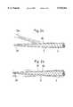
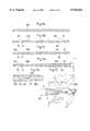
- FIG. 1ais a plan view of a guide wire according to an embodiment of the invention.
- FIG. 1bis a perspective view of a main part of the guide wire
- FIGS. 2a and 2bare sequential views of coating a resin layer on a core wire
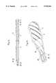
- FIG. 3ais a plan view of a guide wire according to another embodiment of the invention.
- FIG. 3bis a perspective view of a main part of the guide wire
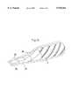
- FIG. 3cis a perspective view of a main part of the wire guide according to a modification form of the invention.
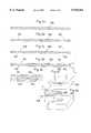
- FIGS. 4a through 4gare sequential views showing how to manufacture the guide wire.
- FIGS. 5a through 5gare sequential views showing how to manufacture the guide wire according to other embodiment of the invention.
- a guide wire 1has a metallic core wire 2 which is made by twisting a plurality of thin threads 21, 22, 23. On an entire surface of the core wire 2, a resin layer 3 is coated. The core wire 2 measures 0.43 mm in diameter, and a leading end of the core wire 2 is diametrically reduced progressively to form a tapered-off section 24. A distal end of the tapered-off section 24 provides a thinnest neck portion to form a thinned tip 25. At the thinned tip 25 of the leading end, a twisted end of the thin threads 21, 22, 23 is tightly united and thermally bonded by means of soldering, resistance welding, laser beam welding, shield-arc welding or the like.
- Each of the thin threads 21, 22, 23is made of a stainless steel which measures 0.25 mm in diameter, and twisted at a pitch of 3.9 mm.
- the tapered-off section 24 of the leading endis made by grinding or polishing to measure 100 mm in length.
- the stainless steelis selected as AISI304 whose diameter is preferably 0.20 ⁇ 0.40 mm.
- the twisiting pitchmay be 2 ⁇ 8 mm.
- the resin layer 3polyurethane, polyamide or PTFE is used.
- the resin layer 3is directly applied or sprayed on the core wire 2 by means of e.g., a spray gun (Gn).
- the resin layer 3may be formed by providing a thermo-shrink tube 31 around the core wire 2 and thermally treating it at 400 ⁇ 450° C. as shown by FIG. 2b. Further, the resin layer 3 may be concurrently formed at the time of extruding the core wire 2 as described hereinafter.
- the twisted threadsare thermally bonded at the thinned tip 25 of the tapered-off section 24 of the leading end.
- Thismakes it possible to freely bend the tapered-off section 24 with no bending tendency towards a specified orientation.
- Thispermits a repeated turns of beding the tapered-off section 24 to remarkably contribute to an extended service life. It is possible to insure a safety with no incident that the twisted thread end of the thinned tip 25 becomes loose to break into the resin layer 3 so as to expose it to the outside.
- FIGS. 3a and 3bshow a guide wire 5 according to another embodiment of the invention in which the thinned tip 25 of the tapered-off section 24 is squelched by means of a pressing procedure to form it into a flat-shaped configuration as designated by numeral 28.
- the flat portion 28has a near distal end side flat section 26 (at the thinned tip 25) and a far distal end side flat section 27 (adjacent to the near distal end side flat section), each of which is in the form of a parallelopipedon.
- the flat portion 28may be shaped into a multiple step type structure in which the thickness of the flat portion 28 progressively reduces by three steps or more as approaching the distal end of the guide wire 5 as shown in FIG. 3c.
- a flat portion 28may be bent in a zigzag manner along an axis to give the far distal end side flat section 27 a level higher than the near distal end side flat section 26 with respect to the axis.
- the thinned tip 25 of the tapered-off section 24is shaped into a columnar configuration. This leads to turning the thinned tip 25 around its axis without eccentrically whirling the thinned tip 25 when rotating the grip of the guide wire 1. This makes it rather difficult to orient the thinned tip 25 in the desired direction when manipulating the guide wire 1.
- FIGS. 4a through 4gshow a method of making the guide wire.
- An elongated wire 100is prepared by twisting thin threads, and then severed by the length of approx. 3500 mm as shown by FIG. 4a.
- a leading end portionis ground or milled to form a thinned portion 101.
- the layer coating wire 104(hereinafter) is cut at a middle of the bonded section 102 and at a middle between the bonded section 102 as shown by FIG. 4e.
- FIGS. 5f and 5gshow another embodiment of the invention in which the tapered-off section 1A has only one end of the twisted wire 100, and the other end is formed into a semi-spherical configuration as designated by R.
- the thinned portion 101is severed at the thermally bonded portion as designated by 102.
- an angular degree of the tapered-off section 24can be determined as desired, and a diameter of the thinned tip 25 measures from 0.10 mm to 0.30 mm, and a thickness of the synthetic resin 103 ranges from 0.12 mm to 0.33 mm.
Landscapes
- Health & Medical Sciences (AREA)
- Life Sciences & Earth Sciences (AREA)
- Engineering & Computer Science (AREA)
- Anesthesiology (AREA)
- Biophysics (AREA)
- Pulmonology (AREA)
- Mechanical Engineering (AREA)
- Biomedical Technology (AREA)
- Heart & Thoracic Surgery (AREA)
- Hematology (AREA)
- Animal Behavior & Ethology (AREA)
- General Health & Medical Sciences (AREA)
- Public Health (AREA)
- Veterinary Medicine (AREA)
- Media Introduction/Drainage Providing Device (AREA)
Abstract
Description
Claims (3)
Priority Applications (1)
| Application Number | Priority Date | Filing Date | Title |
|---|---|---|---|
| US08/885,949US5897819A (en) | 1996-07-10 | 1997-06-30 | Process of making a guide wire for a catheter |
Applications Claiming Priority (2)
| Application Number | Priority Date | Filing Date | Title |
|---|---|---|---|
| JP18102296 | 1996-07-10 | ||
| JP8-181022 | 1996-07-10 |
Related Child Applications (1)
| Application Number | Title | Priority Date | Filing Date |
|---|---|---|---|
| US08/885,949DivisionUS5897819A (en) | 1996-07-10 | 1997-06-30 | Process of making a guide wire for a catheter |
Publications (1)
| Publication Number | Publication Date |
|---|---|
| US5910364Atrue US5910364A (en) | 1999-06-08 |
Family
ID=16093400
Family Applications (2)
| Application Number | Title | Priority Date | Filing Date |
|---|---|---|---|
| US08/744,316Expired - Fee RelatedUS5910364A (en) | 1996-07-10 | 1996-11-07 | Guide wire and a method of making the same |
| US08/885,949Expired - LifetimeUS5897819A (en) | 1996-07-10 | 1997-06-30 | Process of making a guide wire for a catheter |
Family Applications After (1)
| Application Number | Title | Priority Date | Filing Date |
|---|---|---|---|
| US08/885,949Expired - LifetimeUS5897819A (en) | 1996-07-10 | 1997-06-30 | Process of making a guide wire for a catheter |
Country Status (1)
| Country | Link |
|---|---|
| US (2) | US5910364A (en) |
Cited By (52)
| Publication number | Priority date | Publication date | Assignee | Title |
|---|---|---|---|---|
| US6165140A (en) | 1998-12-28 | 2000-12-26 | Micrus Corporation | Composite guidewire |
| US6168571B1 (en)* | 1997-04-15 | 2001-01-02 | Symbiosis Corporation | Linear elastic member |
| US6251085B1 (en)* | 1997-07-04 | 2001-06-26 | Olympus Optical Co., Ltd. | Medical guidewire |
| US6494894B2 (en) | 2000-03-16 | 2002-12-17 | Scimed Life Systems, Inc. | Coated wire |
| JP2003284781A (en)* | 2002-03-28 | 2003-10-07 | Asahi Intecc Co Ltd | Medical guidewire |
| US6671560B2 (en) | 1998-06-12 | 2003-12-30 | Cardiac Pacemakers, Inc. | Modified guidewire for left ventricular access lead |
| US20040054301A1 (en)* | 2002-09-18 | 2004-03-18 | Scimed Life Systems, Inc. | Flexible composite guidewire for intravascular catheter |
| US20040082879A1 (en)* | 2000-01-28 | 2004-04-29 | Klint Henrik S. | Endovascular medical device with plurality of wires |
| EP1520600A1 (en)* | 2003-10-02 | 2005-04-06 | Asahi Intecc Co., Ltd. | A medical guide wire |
| US20050085885A1 (en)* | 1998-08-12 | 2005-04-21 | Cardiac Pacemakers, Inc. | Expandable seal for use with medical device and system |
| US20050096665A1 (en)* | 2003-10-30 | 2005-05-05 | Scimed Life Systems, Inc. | Guidewire having a helically contoured portion |
| US20050096567A1 (en)* | 2003-10-30 | 2005-05-05 | Scimed Life Systems, Inc. | Guidewire having an embedded matrix polymer |
| US6926725B2 (en) | 2002-04-04 | 2005-08-09 | Rex Medical, L.P. | Thrombectomy device with multi-layered rotational wire |
| US20060064036A1 (en)* | 2004-09-21 | 2006-03-23 | Cook Incorporated | Variable flexibility wire guide |
| US7037316B2 (en) | 1997-07-24 | 2006-05-02 | Mcguckin Jr James F | Rotational thrombectomy device |
| US20060100602A1 (en)* | 2001-01-26 | 2006-05-11 | William Cook Europe Aps | Endovascular medical device with plurality of wires |
| US20060106407A1 (en)* | 2004-11-17 | 2006-05-18 | Mcguckin James F Jr | Rotational thrombectomy wire |
| US20070049847A1 (en)* | 2005-08-05 | 2007-03-01 | Cook Incorporated | High performance wire guide |
| US20070288036A1 (en)* | 2006-06-09 | 2007-12-13 | Niranjan Seshadri | Assembly for crossing a chronic total occlusion and method therefor |
| US20090012429A1 (en)* | 2004-08-25 | 2009-01-08 | Heuser Richard R | Catheter guidewire system using concentric wires |
| US20090165784A1 (en)* | 2007-12-28 | 2009-07-02 | Tyco Healthcare Group Lp | Lubricious intubation device |
| US20090299332A1 (en)* | 2008-05-30 | 2009-12-03 | Boston Scientific Scimed, Inc. | Medical device including a polymer sleeve and a coil wound into the polymer sleeve |
| US7645261B2 (en) | 1999-10-22 | 2010-01-12 | Rex Medical, L.P | Double balloon thrombectomy catheter |
| US7657324B2 (en) | 1998-08-12 | 2010-02-02 | Cardiac Pacemakers, Inc. | Seal for use with cardiac lead |
| US8414543B2 (en) | 1999-10-22 | 2013-04-09 | Rex Medical, L.P. | Rotational thrombectomy wire with blocking device |
| US8545418B2 (en) | 2004-08-25 | 2013-10-01 | Richard R. Heuser | Systems and methods for ablation of occlusions within blood vessels |
| US8663259B2 (en) | 2010-05-13 | 2014-03-04 | Rex Medical L.P. | Rotational thrombectomy wire |
| US8764779B2 (en) | 2010-05-13 | 2014-07-01 | Rex Medical, L.P. | Rotational thrombectomy wire |
| US8876796B2 (en) | 2010-12-30 | 2014-11-04 | Claret Medical, Inc. | Method of accessing the left common carotid artery |
| US20150011964A1 (en)* | 2013-07-03 | 2015-01-08 | Boston Scientific Scimed, Inc. | Guidewire |
| US8974489B2 (en) | 2009-07-27 | 2015-03-10 | Claret Medical, Inc. | Dual endovascular filter and methods of use |
| US9023070B2 (en) | 2010-05-13 | 2015-05-05 | Rex Medical, L.P. | Rotational thrombectomy wire coupler |
| US9326843B2 (en) | 2009-01-16 | 2016-05-03 | Claret Medical, Inc. | Intravascular blood filters and methods of use |
| USD760386S1 (en)* | 2014-10-27 | 2016-06-28 | Asahi Intecc Co., Ltd. | Protector for medical device |
| USD774646S1 (en)* | 2015-04-30 | 2016-12-20 | Asahi Intecc Co., Ltd. | Coil body for medical use |
| US9566144B2 (en) | 2015-04-22 | 2017-02-14 | Claret Medical, Inc. | Vascular filters, deflectors, and methods |
| US9636205B2 (en) | 2009-01-16 | 2017-05-02 | Claret Medical, Inc. | Intravascular blood filters and methods of use |
| US9795406B2 (en) | 2010-05-13 | 2017-10-24 | Rex Medical, L.P. | Rotational thrombectomy wire |
| US10258240B1 (en) | 2014-11-24 | 2019-04-16 | Vascular Imaging Corporation | Optical fiber pressure sensor |
| US10327645B2 (en) | 2013-10-04 | 2019-06-25 | Vascular Imaging Corporation | Imaging techniques using an imaging guidewire |
| US10506934B2 (en) | 2012-05-25 | 2019-12-17 | Phyzhon Health Inc. | Optical fiber pressure sensor |
| US10537255B2 (en) | 2013-11-21 | 2020-01-21 | Phyzhon Health Inc. | Optical fiber pressure sensor |
| US10743977B2 (en) | 2009-01-16 | 2020-08-18 | Boston Scientific Scimed, Inc. | Intravascular blood filter |
| US10953204B2 (en) | 2017-01-09 | 2021-03-23 | Boston Scientific Scimed, Inc. | Guidewire with tactile feel |
| US11154390B2 (en) | 2017-12-19 | 2021-10-26 | Claret Medical, Inc. | Systems for protection of the cerebral vasculature during a cardiac procedure |
| US11167115B2 (en)* | 2016-08-02 | 2021-11-09 | Fmd Co., Ltd. | Medical guide wire and manufacturing method of medical guide wire |
| US11191630B2 (en) | 2017-10-27 | 2021-12-07 | Claret Medical, Inc. | Systems and methods for protecting the cerebral vasculature |
| US11337790B2 (en) | 2017-02-22 | 2022-05-24 | Boston Scientific Scimed, Inc. | Systems and methods for protecting the cerebral vasculature |
| US11351023B2 (en) | 2018-08-21 | 2022-06-07 | Claret Medical, Inc. | Systems and methods for protecting the cerebral vasculature |
| US11439491B2 (en) | 2018-04-26 | 2022-09-13 | Claret Medical, Inc. | Systems and methods for protecting the cerebral vasculature |
| US11607301B2 (en) | 2009-01-16 | 2023-03-21 | Boston Scientific Scimed, Inc. | Intravascular blood filters and methods of use |
| US12150851B2 (en) | 2010-12-30 | 2024-11-26 | Claret Medical, Inc. | Method of isolating the cerebral circulation during a cardiac procedure |
Families Citing this family (12)
| Publication number | Priority date | Publication date | Assignee | Title |
|---|---|---|---|---|
| US6059738A (en)* | 1995-06-30 | 2000-05-09 | Meadox Medicals, Inc. | Guidewire having a coated tip |
| WO2006065926A1 (en)* | 2004-12-15 | 2006-06-22 | Cook Incorporated | Multifilar cable catheter |
| US8372017B2 (en)* | 2007-10-30 | 2013-02-12 | General Electric Company | Multi-stranded trackable guidewire |
| US8231926B2 (en) | 2007-12-21 | 2012-07-31 | Innovatech, Llc | Marked precoated medical device and method of manufacturing same |
| US8048471B2 (en)* | 2007-12-21 | 2011-11-01 | Innovatech, Llc | Marked precoated medical device and method of manufacturing same |
| US8231927B2 (en) | 2007-12-21 | 2012-07-31 | Innovatech, Llc | Marked precoated medical device and method of manufacturing same |
| US7811623B2 (en)* | 2007-12-21 | 2010-10-12 | Innovatech, Llc | Marked precoated medical device and method of manufacturing same |
| US7714217B2 (en)* | 2007-12-21 | 2010-05-11 | Innovatech, Llc | Marked precoated strings and method of manufacturing same |
| DE102008012743A1 (en)* | 2008-03-05 | 2009-09-10 | Biotronik Vi Patent Ag | Catheter guidewire and method of making the same |
| US9002435B2 (en)* | 2008-06-30 | 2015-04-07 | General Electric Company | System and method for integrating electromagnetic microsensors in guidewires |
| WO2010030863A1 (en)* | 2008-09-12 | 2010-03-18 | C. R. Bard, Inc. | A hybrid guidewire |
| US8900652B1 (en) | 2011-03-14 | 2014-12-02 | Innovatech, Llc | Marked fluoropolymer surfaces and method of manufacturing same |
Citations (14)
| Publication number | Priority date | Publication date | Assignee | Title |
|---|---|---|---|---|
| US4682607A (en)* | 1985-12-02 | 1987-07-28 | Vlv Associates | Wire guide |
| US4832047A (en)* | 1987-12-15 | 1989-05-23 | Target Therapeutics | Guide wire device |
| JPH0342935A (en)* | 1989-07-11 | 1991-02-25 | Fujitsu Ltd | Advance order protecting circuit |
| JPH0420453A (en)* | 1990-05-15 | 1992-01-24 | Sharp Corp | Control method for transport of media sheet |
| JPH04236965A (en)* | 1990-07-25 | 1992-08-25 | C R Bard Inc | Movable core guide wire |
| US5147317A (en)* | 1990-06-04 | 1992-09-15 | C.R. Bard, Inc. | Low friction varied radiopacity guidewire |
| JPH04292175A (en)* | 1990-12-03 | 1992-10-16 | C R Bard Inc | Guide wire for use with catheter and method for manufacture thereof |
| US5217026A (en)* | 1992-04-06 | 1993-06-08 | Kingston Technologies, Inc. | Guidewires with lubricious surface and method of their production |
| US5230348A (en)* | 1990-10-12 | 1993-07-27 | Nippon Seisen Co., Ltd. | Guide wire for a catheter |
| US5269759A (en)* | 1992-07-28 | 1993-12-14 | Cordis Corporation | Magnetic guidewire coupling for vascular dilatation apparatus |
| JPH0623543A (en)* | 1992-01-16 | 1994-02-01 | Nippon Steel Corp | Pipe end seal welding method for double pipe |
| US5409470A (en)* | 1993-05-07 | 1995-04-25 | C. R. Bard, Inc. | Dilatation catheter and guidewire with threaded tip connection |
| US5433200A (en)* | 1990-07-09 | 1995-07-18 | Lake Region Manufacturing, Inc. | Low profile, coated, steerable guide wire |
| US5498250A (en)* | 1994-05-18 | 1996-03-12 | Scimed Life Systems, Inc. | Catheter guide wire with multiple radiopacity |
Family Cites Families (2)
| Publication number | Priority date | Publication date | Assignee | Title |
|---|---|---|---|---|
| DE3327779A1 (en)* | 1983-08-02 | 1985-02-14 | B. Braun Melsungen Ag, 3508 Melsungen | MANDRIN FOR TUBULAR CATHETERS AND BODY SEEDS |
| DE3516052A1 (en)* | 1985-05-04 | 1986-11-13 | B. Braun Melsungen Ag, 3508 Melsungen | LEADERSHIP |
- 1996
- 1996-11-07USUS08/744,316patent/US5910364A/ennot_activeExpired - Fee Related
- 1997
- 1997-06-30USUS08/885,949patent/US5897819A/ennot_activeExpired - Lifetime
Patent Citations (15)
| Publication number | Priority date | Publication date | Assignee | Title |
|---|---|---|---|---|
| US4682607A (en)* | 1985-12-02 | 1987-07-28 | Vlv Associates | Wire guide |
| US4832047A (en)* | 1987-12-15 | 1989-05-23 | Target Therapeutics | Guide wire device |
| JPH0342935A (en)* | 1989-07-11 | 1991-02-25 | Fujitsu Ltd | Advance order protecting circuit |
| JPH0420453A (en)* | 1990-05-15 | 1992-01-24 | Sharp Corp | Control method for transport of media sheet |
| US5365942A (en)* | 1990-06-04 | 1994-11-22 | C. R. Bard, Inc. | Guidewire tip construction |
| US5147317A (en)* | 1990-06-04 | 1992-09-15 | C.R. Bard, Inc. | Low friction varied radiopacity guidewire |
| US5433200A (en)* | 1990-07-09 | 1995-07-18 | Lake Region Manufacturing, Inc. | Low profile, coated, steerable guide wire |
| JPH04236965A (en)* | 1990-07-25 | 1992-08-25 | C R Bard Inc | Movable core guide wire |
| US5230348A (en)* | 1990-10-12 | 1993-07-27 | Nippon Seisen Co., Ltd. | Guide wire for a catheter |
| JPH04292175A (en)* | 1990-12-03 | 1992-10-16 | C R Bard Inc | Guide wire for use with catheter and method for manufacture thereof |
| JPH0623543A (en)* | 1992-01-16 | 1994-02-01 | Nippon Steel Corp | Pipe end seal welding method for double pipe |
| US5217026A (en)* | 1992-04-06 | 1993-06-08 | Kingston Technologies, Inc. | Guidewires with lubricious surface and method of their production |
| US5269759A (en)* | 1992-07-28 | 1993-12-14 | Cordis Corporation | Magnetic guidewire coupling for vascular dilatation apparatus |
| US5409470A (en)* | 1993-05-07 | 1995-04-25 | C. R. Bard, Inc. | Dilatation catheter and guidewire with threaded tip connection |
| US5498250A (en)* | 1994-05-18 | 1996-03-12 | Scimed Life Systems, Inc. | Catheter guide wire with multiple radiopacity |
Cited By (102)
| Publication number | Priority date | Publication date | Assignee | Title |
|---|---|---|---|---|
| US6168571B1 (en)* | 1997-04-15 | 2001-01-02 | Symbiosis Corporation | Linear elastic member |
| US6251085B1 (en)* | 1997-07-04 | 2001-06-26 | Olympus Optical Co., Ltd. | Medical guidewire |
| US7037316B2 (en) | 1997-07-24 | 2006-05-02 | Mcguckin Jr James F | Rotational thrombectomy device |
| US7507246B2 (en) | 1997-07-24 | 2009-03-24 | Rex Medical, L.P. | Rotational thrombectomy device |
| US6671560B2 (en) | 1998-06-12 | 2003-12-30 | Cardiac Pacemakers, Inc. | Modified guidewire for left ventricular access lead |
| US7412290B2 (en) | 1998-08-12 | 2008-08-12 | Cardiac Pacemakers, Inc. | Seal for use with medical device and system |
| US7657324B2 (en) | 1998-08-12 | 2010-02-02 | Cardiac Pacemakers, Inc. | Seal for use with cardiac lead |
| US6901288B2 (en) | 1998-08-12 | 2005-05-31 | Cardiac Pacemakers, Inc. | Sealing assembly for intravenous lead |
| US20050085885A1 (en)* | 1998-08-12 | 2005-04-21 | Cardiac Pacemakers, Inc. | Expandable seal for use with medical device and system |
| US6595932B2 (en) | 1998-12-28 | 2003-07-22 | Micrus Corporation | Composite guidewire |
| US6165140A (en) | 1998-12-28 | 2000-12-26 | Micrus Corporation | Composite guidewire |
| US6432066B1 (en) | 1998-12-28 | 2002-08-13 | Micrus Corporation | Composite guidewire |
| US7014616B2 (en) | 1998-12-28 | 2006-03-21 | Micrus Corporation | Composite guidewire |
| US7645261B2 (en) | 1999-10-22 | 2010-01-12 | Rex Medical, L.P | Double balloon thrombectomy catheter |
| US8414543B2 (en) | 1999-10-22 | 2013-04-09 | Rex Medical, L.P. | Rotational thrombectomy wire with blocking device |
| US8435218B2 (en) | 1999-10-22 | 2013-05-07 | Rex Medical, L.P. | Double balloon thrombectomy catheter |
| US7909801B2 (en) | 1999-10-22 | 2011-03-22 | Rex Medical, L.P. | Double balloon thrombectomy catheter |
| US9017294B2 (en) | 1999-10-22 | 2015-04-28 | Rex Medical, L.P. | Rotational thrombectomy wire with blocking device |
| US20040082879A1 (en)* | 2000-01-28 | 2004-04-29 | Klint Henrik S. | Endovascular medical device with plurality of wires |
| US6494894B2 (en) | 2000-03-16 | 2002-12-17 | Scimed Life Systems, Inc. | Coated wire |
| US8721625B2 (en) | 2001-01-26 | 2014-05-13 | Cook Medical Technologies Llc | Endovascular medical device with plurality of wires |
| US20060100602A1 (en)* | 2001-01-26 | 2006-05-11 | William Cook Europe Aps | Endovascular medical device with plurality of wires |
| JP2003284781A (en)* | 2002-03-28 | 2003-10-07 | Asahi Intecc Co Ltd | Medical guidewire |
| US6926725B2 (en) | 2002-04-04 | 2005-08-09 | Rex Medical, L.P. | Thrombectomy device with multi-layered rotational wire |
| US20040054301A1 (en)* | 2002-09-18 | 2004-03-18 | Scimed Life Systems, Inc. | Flexible composite guidewire for intravascular catheter |
| US7309318B2 (en) | 2002-09-18 | 2007-12-18 | Boston Scientific Scimed, Inc. | Flexible composite guidewire for intravascular catheter |
| WO2004026386A3 (en)* | 2002-09-18 | 2004-07-15 | Scimed Life Systems Inc | Flexible composite guidewire for intravascular catheter |
| US7399283B2 (en) | 2003-10-02 | 2008-07-15 | Asahi Intecc Co. | Medical guide wire having a stepwisely thickness-reduced but breadth-increased distal tip structure |
| EP1520600A1 (en)* | 2003-10-02 | 2005-04-06 | Asahi Intecc Co., Ltd. | A medical guide wire |
| US20050096568A1 (en)* | 2003-10-02 | 2005-05-05 | Asahi Intecc Co. | Medical guide wire |
| CN1618478B (en)* | 2003-10-02 | 2010-09-22 | 朝日印帝克股份有限公司 | Medical guide wire |
| US7553287B2 (en) | 2003-10-30 | 2009-06-30 | Boston Scientific Scimed, Inc. | Guidewire having an embedded matrix polymer |
| US20050096665A1 (en)* | 2003-10-30 | 2005-05-05 | Scimed Life Systems, Inc. | Guidewire having a helically contoured portion |
| US20050096567A1 (en)* | 2003-10-30 | 2005-05-05 | Scimed Life Systems, Inc. | Guidewire having an embedded matrix polymer |
| US20090012429A1 (en)* | 2004-08-25 | 2009-01-08 | Heuser Richard R | Catheter guidewire system using concentric wires |
| US8545418B2 (en) | 2004-08-25 | 2013-10-01 | Richard R. Heuser | Systems and methods for ablation of occlusions within blood vessels |
| US20060064036A1 (en)* | 2004-09-21 | 2006-03-23 | Cook Incorporated | Variable flexibility wire guide |
| US8062317B2 (en) | 2004-11-17 | 2011-11-22 | Rex Medical, L.P. | Rotational thrombectomy wire |
| US9474543B2 (en) | 2004-11-17 | 2016-10-25 | Argon Medical Devices, Inc. | Rotational thrombectomy wire |
| US7819887B2 (en) | 2004-11-17 | 2010-10-26 | Rex Medical, L.P. | Rotational thrombectomy wire |
| US10117671B2 (en) | 2004-11-17 | 2018-11-06 | Argon Medical Devices Inc. | Rotational thrombectomy device |
| US20060106407A1 (en)* | 2004-11-17 | 2006-05-18 | Mcguckin James F Jr | Rotational thrombectomy wire |
| US8465511B2 (en) | 2004-11-17 | 2013-06-18 | Rex Medical, L.P. | Rotational thrombectomy wire |
| US8043232B2 (en) | 2005-08-05 | 2011-10-25 | Cook Medical Technologies Llc | High performance wire guide |
| US20070049847A1 (en)* | 2005-08-05 | 2007-03-01 | Cook Incorporated | High performance wire guide |
| US20070288036A1 (en)* | 2006-06-09 | 2007-12-13 | Niranjan Seshadri | Assembly for crossing a chronic total occlusion and method therefor |
| US20090165784A1 (en)* | 2007-12-28 | 2009-07-02 | Tyco Healthcare Group Lp | Lubricious intubation device |
| US20090299332A1 (en)* | 2008-05-30 | 2009-12-03 | Boston Scientific Scimed, Inc. | Medical device including a polymer sleeve and a coil wound into the polymer sleeve |
| US8002715B2 (en) | 2008-05-30 | 2011-08-23 | Boston Scientific Scimed, Inc. | Medical device including a polymer sleeve and a coil wound into the polymer sleeve |
| US9326843B2 (en) | 2009-01-16 | 2016-05-03 | Claret Medical, Inc. | Intravascular blood filters and methods of use |
| US10743977B2 (en) | 2009-01-16 | 2020-08-18 | Boston Scientific Scimed, Inc. | Intravascular blood filter |
| US12201507B2 (en) | 2009-01-16 | 2025-01-21 | Claret Medical, Inc. | Intravascular blood filters and methods of use |
| US12048618B2 (en) | 2009-01-16 | 2024-07-30 | Boston Scientific Scimed, Inc. | Intravascular blood filter |
| US9636205B2 (en) | 2009-01-16 | 2017-05-02 | Claret Medical, Inc. | Intravascular blood filters and methods of use |
| US11607301B2 (en) | 2009-01-16 | 2023-03-21 | Boston Scientific Scimed, Inc. | Intravascular blood filters and methods of use |
| US11364106B2 (en) | 2009-01-16 | 2022-06-21 | Boston Scientific Scimed, Inc. | Intravascular blood filter |
| US11284986B2 (en) | 2009-01-16 | 2022-03-29 | Claret Medical, Inc. | Intravascular blood filters and methods of use |
| US11191631B2 (en) | 2009-07-27 | 2021-12-07 | Boston Scientific Scimed, Inc. | Dual endovascular filter and methods of use |
| US8974489B2 (en) | 2009-07-27 | 2015-03-10 | Claret Medical, Inc. | Dual endovascular filter and methods of use |
| US10130458B2 (en) | 2009-07-27 | 2018-11-20 | Claret Medical, Inc. | Dual endovascular filter and methods of use |
| US9282992B2 (en) | 2010-05-13 | 2016-03-15 | Rex Medical, L.P. | Rotational thrombectomy wire |
| US9023070B2 (en) | 2010-05-13 | 2015-05-05 | Rex Medical, L.P. | Rotational thrombectomy wire coupler |
| US8764779B2 (en) | 2010-05-13 | 2014-07-01 | Rex Medical, L.P. | Rotational thrombectomy wire |
| US10517630B2 (en) | 2010-05-13 | 2019-12-31 | Rex Medical, L.P. | Rotational thrombectomy wire |
| US8663259B2 (en) | 2010-05-13 | 2014-03-04 | Rex Medical L.P. | Rotational thrombectomy wire |
| US9700346B2 (en) | 2010-05-13 | 2017-07-11 | Rex Medical, L.P. | Rotational thrombectomy wire |
| US9795406B2 (en) | 2010-05-13 | 2017-10-24 | Rex Medical, L.P. | Rotational thrombectomy wire |
| US10064645B2 (en) | 2010-05-13 | 2018-09-04 | Rex Medical, L.P. | Rotational thrombectomy wire |
| US9924957B2 (en) | 2010-08-23 | 2018-03-27 | Argon Medical Devices, Inc. | Rotational thrombectomy wire with blocking device |
| US9017364B2 (en) | 2010-12-30 | 2015-04-28 | Claret Medical, Inc. | Deflectable intravascular filter |
| US11141258B2 (en) | 2010-12-30 | 2021-10-12 | Claret Medical, Inc. | Method of isolating the cerebral circulation during a cardiac procedure |
| US9980805B2 (en) | 2010-12-30 | 2018-05-29 | Claret Medical, Inc. | Aortic embolic protection device |
| US9943395B2 (en) | 2010-12-30 | 2018-04-17 | Claret Medical, Inc. | Deflectable intravascular filter |
| US8876796B2 (en) | 2010-12-30 | 2014-11-04 | Claret Medical, Inc. | Method of accessing the left common carotid artery |
| US12150851B2 (en) | 2010-12-30 | 2024-11-26 | Claret Medical, Inc. | Method of isolating the cerebral circulation during a cardiac procedure |
| US10058411B2 (en) | 2010-12-30 | 2018-08-28 | Claret Madical, Inc. | Method of isolating the cerebral circulation during a cardiac procedure |
| US9259306B2 (en) | 2010-12-30 | 2016-02-16 | Claret Medical, Inc. | Aortic embolic protection device |
| US9345565B2 (en) | 2010-12-30 | 2016-05-24 | Claret Medical, Inc. | Steerable dual filter cerebral protection system |
| US9055997B2 (en) | 2010-12-30 | 2015-06-16 | Claret Medical, Inc. | Method of isolating the cerebral circulation during a cardiac procedure |
| US9492264B2 (en) | 2010-12-30 | 2016-11-15 | Claret Medical, Inc. | Embolic protection device for protecting the cerebral vasculature |
| US10506934B2 (en) | 2012-05-25 | 2019-12-17 | Phyzhon Health Inc. | Optical fiber pressure sensor |
| US11172833B2 (en) | 2012-05-25 | 2021-11-16 | Phyzhon Health Inc. | Optical fiber pressure sensor guidewire |
| US20150011964A1 (en)* | 2013-07-03 | 2015-01-08 | Boston Scientific Scimed, Inc. | Guidewire |
| US11298026B2 (en) | 2013-10-04 | 2022-04-12 | Phyzhon Health Inc. | Imaging techniques using an imaging guidewire |
| US10327645B2 (en) | 2013-10-04 | 2019-06-25 | Vascular Imaging Corporation | Imaging techniques using an imaging guidewire |
| US10537255B2 (en) | 2013-11-21 | 2020-01-21 | Phyzhon Health Inc. | Optical fiber pressure sensor |
| US11696692B2 (en) | 2013-11-21 | 2023-07-11 | Phyzhon Health Inc. | Optical fiber pressure sensor |
| USD760386S1 (en)* | 2014-10-27 | 2016-06-28 | Asahi Intecc Co., Ltd. | Protector for medical device |
| US10258240B1 (en) | 2014-11-24 | 2019-04-16 | Vascular Imaging Corporation | Optical fiber pressure sensor |
| US9566144B2 (en) | 2015-04-22 | 2017-02-14 | Claret Medical, Inc. | Vascular filters, deflectors, and methods |
| US10449028B2 (en) | 2015-04-22 | 2019-10-22 | Claret Medical, Inc. | Vascular filters, deflectors, and methods |
| USD774646S1 (en)* | 2015-04-30 | 2016-12-20 | Asahi Intecc Co., Ltd. | Coil body for medical use |
| US11167115B2 (en)* | 2016-08-02 | 2021-11-09 | Fmd Co., Ltd. | Medical guide wire and manufacturing method of medical guide wire |
| US10953204B2 (en) | 2017-01-09 | 2021-03-23 | Boston Scientific Scimed, Inc. | Guidewire with tactile feel |
| US11337790B2 (en) | 2017-02-22 | 2022-05-24 | Boston Scientific Scimed, Inc. | Systems and methods for protecting the cerebral vasculature |
| US11191630B2 (en) | 2017-10-27 | 2021-12-07 | Claret Medical, Inc. | Systems and methods for protecting the cerebral vasculature |
| US12097108B2 (en) | 2017-10-27 | 2024-09-24 | Claret Medical, Inc. | Systems and methods for protecting the cerebral vasculature |
| US12064332B2 (en) | 2017-12-19 | 2024-08-20 | Claret Medical, Inc. | Systems and methods for protecting the cerebral vasculature |
| US11154390B2 (en) | 2017-12-19 | 2021-10-26 | Claret Medical, Inc. | Systems for protection of the cerebral vasculature during a cardiac procedure |
| US11439491B2 (en) | 2018-04-26 | 2022-09-13 | Claret Medical, Inc. | Systems and methods for protecting the cerebral vasculature |
| US12409022B2 (en) | 2018-04-26 | 2025-09-09 | Claret Medical, Inc. | Systems and methods for protecting the cerebral vasculature |
| US11351023B2 (en) | 2018-08-21 | 2022-06-07 | Claret Medical, Inc. | Systems and methods for protecting the cerebral vasculature |
Also Published As
| Publication number | Publication date |
|---|---|
| US5897819A (en) | 1999-04-27 |
Similar Documents
| Publication | Publication Date | Title |
|---|---|---|
| US5910364A (en) | Guide wire and a method of making the same | |
| US4832047A (en) | Guide wire device | |
| US8936558B2 (en) | Medical device for navigation through anatomy and method of making same | |
| US4619274A (en) | Torsional guide wire with attenuated diameter | |
| US8128580B2 (en) | Guide wire | |
| JP5441336B2 (en) | Guide wire | |
| EP0826389B1 (en) | Guide wire | |
| US20190290884A1 (en) | Catheter and method for manufacturing catheter | |
| JP4028245B2 (en) | Guide wire | |
| US20090240235A1 (en) | Medical catheter tube and process for producing the same | |
| JP2004508147A (en) | Steerable stylet with increased torsional transmission | |
| WO2016047499A1 (en) | Guide wire | |
| JPH08257128A (en) | Medical tube | |
| EP2001378A2 (en) | Compression pin with opposed threaded regions | |
| JPH08308933A (en) | Medical tube | |
| KR20170134305A (en) | Guide wire | |
| JP5526218B2 (en) | Guide wire | |
| JPH1071209A (en) | Guide wire | |
| JP2014233312A (en) | Guide wire | |
| JP7529799B2 (en) | Guidewires | |
| JP2025508191A (en) | Guidewire with reduced stiffness section - Patents.com |
Legal Events
| Date | Code | Title | Description |
|---|---|---|---|
| AS | Assignment | Owner name:ASAHI INTECC CO., LTD., JAPAN Free format text:ASSIGNMENT OF ASSIGNORS INTEREST;ASSIGNORS:MIYATA, NAOHIKO;MOMOTA, MASASHI;SARUTA, MINORU;REEL/FRAME:008309/0188 Effective date:19961026 | |
| FEPP | Fee payment procedure | Free format text:PAYOR NUMBER ASSIGNED (ORIGINAL EVENT CODE: ASPN); ENTITY STATUS OF PATENT OWNER: LARGE ENTITY | |
| FEPP | Fee payment procedure | Free format text:PETITION RELATED TO MAINTENANCE FEES GRANTED (ORIGINAL EVENT CODE: PMFG); ENTITY STATUS OF PATENT OWNER: LARGE ENTITY | |
| REMI | Maintenance fee reminder mailed | ||
| REIN | Reinstatement after maintenance fee payment confirmed | ||
| FP | Lapsed due to failure to pay maintenance fee | Effective date:20030608 | |
| FPAY | Fee payment | Year of fee payment:4 | |
| SULP | Surcharge for late payment | ||
| PRDP | Patent reinstated due to the acceptance of a late maintenance fee | Effective date:20030902 | |
| FPAY | Fee payment | Year of fee payment:8 | |
| FEPP | Fee payment procedure | Free format text:PAT HOLDER NO LONGER CLAIMS SMALL ENTITY STATUS, ENTITY STATUS SET TO UNDISCOUNTED (ORIGINAL EVENT CODE: STOL); ENTITY STATUS OF PATENT OWNER: LARGE ENTITY | |
| SULP | Surcharge for late payment | ||
| REMI | Maintenance fee reminder mailed | ||
| LAPS | Lapse for failure to pay maintenance fees | ||
| STCH | Information on status: patent discontinuation | Free format text:PATENT EXPIRED DUE TO NONPAYMENT OF MAINTENANCE FEES UNDER 37 CFR 1.362 | |
| FP | Lapsed due to failure to pay maintenance fee | Effective date:20110608 |