US5909250A - Adaptive video compression using variable quantization - Google Patents
Adaptive video compression using variable quantizationDownload PDFInfo
- Publication number
- US5909250A US5909250AUS08/968,796US96879697AUS5909250AUS 5909250 AUS5909250 AUS 5909250AUS 96879697 AUS96879697 AUS 96879697AUS 5909250 AUS5909250 AUS 5909250A
- Authority
- US
- United States
- Prior art keywords
- video data
- compressed video
- compressed
- compression
- quantization factors
- Prior art date
- Legal status (The legal status is an assumption and is not a legal conclusion. Google has not performed a legal analysis and makes no representation as to the accuracy of the status listed.)
- Expired - Lifetime
Links
Images


Classifications
- H—ELECTRICITY
- H04—ELECTRIC COMMUNICATION TECHNIQUE
- H04N—PICTORIAL COMMUNICATION, e.g. TELEVISION
- H04N7/00—Television systems
- H04N7/24—Systems for the transmission of television signals using pulse code modulation
- H04N7/52—Systems for transmission of a pulse code modulated video signal with one or more other pulse code modulated signals, e.g. an audio signal or a synchronizing signal
- H04N7/54—Systems for transmission of a pulse code modulated video signal with one or more other pulse code modulated signals, e.g. an audio signal or a synchronizing signal the signals being synchronous
- H—ELECTRICITY
- H04—ELECTRIC COMMUNICATION TECHNIQUE
- H04N—PICTORIAL COMMUNICATION, e.g. TELEVISION
- H04N19/00—Methods or arrangements for coding, decoding, compressing or decompressing digital video signals
- H04N19/10—Methods or arrangements for coding, decoding, compressing or decompressing digital video signals using adaptive coding
- H04N19/102—Methods or arrangements for coding, decoding, compressing or decompressing digital video signals using adaptive coding characterised by the element, parameter or selection affected or controlled by the adaptive coding
- H04N19/124—Quantisation
- H04N19/126—Details of normalisation or weighting functions, e.g. normalisation matrices or variable uniform quantisers
- H—ELECTRICITY
- H04—ELECTRIC COMMUNICATION TECHNIQUE
- H04N—PICTORIAL COMMUNICATION, e.g. TELEVISION
- H04N19/00—Methods or arrangements for coding, decoding, compressing or decompressing digital video signals
- H04N19/10—Methods or arrangements for coding, decoding, compressing or decompressing digital video signals using adaptive coding
- H04N19/134—Methods or arrangements for coding, decoding, compressing or decompressing digital video signals using adaptive coding characterised by the element, parameter or criterion affecting or controlling the adaptive coding
- H04N19/157—Assigned coding mode, i.e. the coding mode being predefined or preselected to be further used for selection of another element or parameter
- H04N19/16—Assigned coding mode, i.e. the coding mode being predefined or preselected to be further used for selection of another element or parameter for a given display mode, e.g. for interlaced or progressive display mode
- H—ELECTRICITY
- H04—ELECTRIC COMMUNICATION TECHNIQUE
- H04N—PICTORIAL COMMUNICATION, e.g. TELEVISION
- H04N19/00—Methods or arrangements for coding, decoding, compressing or decompressing digital video signals
- H04N19/10—Methods or arrangements for coding, decoding, compressing or decompressing digital video signals using adaptive coding
- H04N19/169—Methods or arrangements for coding, decoding, compressing or decompressing digital video signals using adaptive coding characterised by the coding unit, i.e. the structural portion or semantic portion of the video signal being the object or the subject of the adaptive coding
- H04N19/17—Methods or arrangements for coding, decoding, compressing or decompressing digital video signals using adaptive coding characterised by the coding unit, i.e. the structural portion or semantic portion of the video signal being the object or the subject of the adaptive coding the unit being an image region, e.g. an object
- H04N19/176—Methods or arrangements for coding, decoding, compressing or decompressing digital video signals using adaptive coding characterised by the coding unit, i.e. the structural portion or semantic portion of the video signal being the object or the subject of the adaptive coding the unit being an image region, e.g. an object the region being a block, e.g. a macroblock
- H—ELECTRICITY
- H04—ELECTRIC COMMUNICATION TECHNIQUE
- H04N—PICTORIAL COMMUNICATION, e.g. TELEVISION
- H04N19/00—Methods or arrangements for coding, decoding, compressing or decompressing digital video signals
- H04N19/10—Methods or arrangements for coding, decoding, compressing or decompressing digital video signals using adaptive coding
- H04N19/169—Methods or arrangements for coding, decoding, compressing or decompressing digital video signals using adaptive coding characterised by the coding unit, i.e. the structural portion or semantic portion of the video signal being the object or the subject of the adaptive coding
- H04N19/186—Methods or arrangements for coding, decoding, compressing or decompressing digital video signals using adaptive coding characterised by the coding unit, i.e. the structural portion or semantic portion of the video signal being the object or the subject of the adaptive coding the unit being a colour or a chrominance component
- H—ELECTRICITY
- H04—ELECTRIC COMMUNICATION TECHNIQUE
- H04N—PICTORIAL COMMUNICATION, e.g. TELEVISION
- H04N19/00—Methods or arrangements for coding, decoding, compressing or decompressing digital video signals
- H04N19/42—Methods or arrangements for coding, decoding, compressing or decompressing digital video signals characterised by implementation details or hardware specially adapted for video compression or decompression, e.g. dedicated software implementation
- H04N19/423—Methods or arrangements for coding, decoding, compressing or decompressing digital video signals characterised by implementation details or hardware specially adapted for video compression or decompression, e.g. dedicated software implementation characterised by memory arrangements
- H—ELECTRICITY
- H04—ELECTRIC COMMUNICATION TECHNIQUE
- H04N—PICTORIAL COMMUNICATION, e.g. TELEVISION
- H04N19/00—Methods or arrangements for coding, decoding, compressing or decompressing digital video signals
- H04N19/46—Embedding additional information in the video signal during the compression process
- H—ELECTRICITY
- H04—ELECTRIC COMMUNICATION TECHNIQUE
- H04N—PICTORIAL COMMUNICATION, e.g. TELEVISION
- H04N19/00—Methods or arrangements for coding, decoding, compressing or decompressing digital video signals
- H04N19/60—Methods or arrangements for coding, decoding, compressing or decompressing digital video signals using transform coding
- H04N19/61—Methods or arrangements for coding, decoding, compressing or decompressing digital video signals using transform coding in combination with predictive coding
- H—ELECTRICITY
- H04—ELECTRIC COMMUNICATION TECHNIQUE
- H04N—PICTORIAL COMMUNICATION, e.g. TELEVISION
- H04N21/00—Selective content distribution, e.g. interactive television or video on demand [VOD]
- H04N21/40—Client devices specifically adapted for the reception of or interaction with content, e.g. set-top-box [STB]; Operations thereof
- H04N21/41—Structure of client; Structure of client peripherals
- H04N21/414—Specialised client platforms, e.g. receiver in car or embedded in a mobile appliance
- H04N21/4143—Specialised client platforms, e.g. receiver in car or embedded in a mobile appliance embedded in a Personal Computer [PC]
- G—PHYSICS
- G09—EDUCATION; CRYPTOGRAPHY; DISPLAY; ADVERTISING; SEALS
- G09G—ARRANGEMENTS OR CIRCUITS FOR CONTROL OF INDICATING DEVICES USING STATIC MEANS TO PRESENT VARIABLE INFORMATION
- G09G2340/00—Aspects of display data processing
- G09G2340/02—Handling of images in compressed format, e.g. JPEG, MPEG
- H—ELECTRICITY
- H04—ELECTRIC COMMUNICATION TECHNIQUE
- H04N—PICTORIAL COMMUNICATION, e.g. TELEVISION
- H04N19/00—Methods or arrangements for coding, decoding, compressing or decompressing digital video signals
- H04N19/10—Methods or arrangements for coding, decoding, compressing or decompressing digital video signals using adaptive coding
- H04N19/134—Methods or arrangements for coding, decoding, compressing or decompressing digital video signals using adaptive coding characterised by the element, parameter or criterion affecting or controlling the adaptive coding
- H04N19/146—Data rate or code amount at the encoder output
- H04N19/149—Data rate or code amount at the encoder output by estimating the code amount by means of a model, e.g. mathematical model or statistical model
- H—ELECTRICITY
- H04—ELECTRIC COMMUNICATION TECHNIQUE
- H04N—PICTORIAL COMMUNICATION, e.g. TELEVISION
- H04N19/00—Methods or arrangements for coding, decoding, compressing or decompressing digital video signals
- H04N19/10—Methods or arrangements for coding, decoding, compressing or decompressing digital video signals using adaptive coding
- H04N19/134—Methods or arrangements for coding, decoding, compressing or decompressing digital video signals using adaptive coding characterised by the element, parameter or criterion affecting or controlling the adaptive coding
- H04N19/146—Data rate or code amount at the encoder output
- H04N19/15—Data rate or code amount at the encoder output by monitoring actual compressed data size at the memory before deciding storage at the transmission buffer
Definitions
- the inventionrelates to compression coding of a video program, and more particularly to an adaptive method for encoding successive frames of the video program.
- a video sourcetypically a video tape recorder
- the videomay be edited in digital form and written back to a video device.
- Video editingpresents a large computational and storage demand, easily seen in the sheer data volume of a video program--30 frames per second, over 300,000 pixels per frame, and several bits per pixel.
- the video image datacan be compressed as they are read, e.g., from video tape, and stored on disk. The data are then decompressed when viewed during editing or playback.
- Selecting a video data compression methodis a tradeoff between quality and quantity. More aggressive compression methods will reduce the amount of compressed data, but may result in lower-quality decompressed images. Generally, recovering the quality of the decompressed image requires the use of less-aggressive compression. Data compression algorithms generally have one or more adjustable parameters that control this tradeoff between quality and quantity; these coefficients are called "quantization factors" or "Q-factors.”
- the amount of compressed data produced for a frame of a video programwill vary frame-to-frame as the content of the frames varies.
- a single set of Q-factorswas used to encode each clip of a video program to be edited. The result was that the easy-to-compress program material, material that could have retained adequate quality even at more aggressive compression levels, consumed more data than required to present a good picture. Other harder-to-compress program material, material that required less-aggressive compression to avoid compression artifacts, was recorded at compromised quality. Additionally, when such material was edited, the editor was constrained to edit together only material that had been recorded with the same Q-factors.
- the inventionfeatures, in general, a method for compressing video data by adjusting compression parameters (e.g., Q-factors) used by a compression coder as the video is being compressed.
- the compression coderis located on a peripheral controller connected to a host computer.
- the video dataare compressed in portions, and each portion (e.g., a frame or a field) has an associated set of compression parameters used to compress that portion.
- the size of compressed video data resulting from compressing each portionis sensed, and the compression parameters are automatically changed as a function of the sensed size of the compressed video data.
- the changed parametersare loaded into the control registers of the compression coder and used in compressing the next portion of video.
- An indication of the compression parameters used in compressing each portion of videois stored with the compressed video to permit the proper parameters to be used in decompression.
- the methodenables real-time adjustments in the compression parameters to match the quality setting for the program material to attain acceptable picture quality and data rates.
- the adjusting of compression parametersincludes determining whether the size of compressed video data exceeds a predetermined upper threshold value, and, if so, loading into the control registers new compression parameters that specify greater compression and lower quality than the original compression parameters.
- the adjusting of compression parametersalso includes determining whether the size of the compressed video data is less than a predetermined lower threshold value, and, if so, loading into the control registers new compression parameters that specify lower compression and greater quality than the original compression parameters.
- the compression parametersare loaded into the control registers of the compression coder under the control of a state machine between compression of consecutive portions of video.
- the compressed video dataare stored into buffers for a mass storage device of the host computer.
- the peripheral controllercommunicates to the host computer an index value indicating the compression parameters with which each portion of video data were compressed and with which the compressed video data can be decompressed.
- the compressed video data and decompression parameters corresponding to the index valueare stored onto a mass storage device of the host computer.
- the peripheral controlleralso communicates to the host computer a count indicating the size of the compressed video data, and the host computer stores the count onto the mass storage device with the compressed data.
- the compressed video dataare queued through a FIFO before storing, the FIFO allowing the host computer to process the stored compressed video data asynchronously from the compressing.
- the preferred use of the inventionis on a video editing system implemented by a host computer, an associated peripheral controller, and software controlling the two to carry out video editing functionality.
- the inventionfeatures the following advantages.
- a usercan specify a favorable trade-off level between compression quality and quantity, and the compression method will adapt to varying program material to maintain that level.
- Video segments recorded with different quality settingscan be edited together; the settings for one segment will not cause another segment to be incorrectly decoded.
- the Q-factor informationmay be synthesized in the host computer so that bus bandwidth need not be consumed copying full Q-factor sets between the peripheral board and the host microcomputer.
- the Q-factor qualification for each frameis computed almost "for free" as a side-effect of compressing the previous frame.
- FIG. 1is a diagrammatic perspective view of components used in a video editing system operating according to the invention.
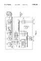
- FIG. 2is a block diagram of a host computer and a video peripheral board used in the system of FIG. 1.
- FIG. 3is a block diagram of an alternate organization of the host computer.
- FIG. 4is a block diagram detailing some of the features of the video peripheral board of FIG. 2.
- FIG. 5is a diagram illustrating de-interlacing, an operation performed by the peripheral board of FIGS. 2 and 4.
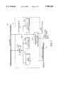
- FIG. 6shows the format for a packet of compressed video data.
- FIG. 7is a block diagram of the bus control circuit of FIG. 2.
- FIG. 8shows the data structures by which the host communicates with the peripheral.
- FIG. 9is flow chart showing the operation of the system.
- video editing system 11includes peripheral board 10 that plugs into host computer 12.
- Other componentsinclude video tape recorder (VTR) 16, monitor 18, keyboard 20, mouse 22, and mass storage disk 24.
- VTRvideo tape recorder
- the software providing video editing functionalityis divided into two portions, one portion 26 that executes on the host computer's central processing unit (CPU) 28, generally providing a user interface and supervision, and one portion 14 that executes on the peripheral board, generally controlling the peripheral board, data transfer within the peripheral board, and data transfer between the host computer and the peripheral.
- CPUcentral processing unit
- video editing system 11video is read through video input port 30, and audio is read through audio input port 32. As they are read, the video is digitized and compressed, and the audio is digitized. The video and audio are stored on the disk 24. The compressed video/audio data may be decompressed and played back onto display 18 and speakers (not shown).
- Video editing software 26allows a user to assemble portions of the compressed video and audio into a video/audio program. As the user edits the program, he can play it and rearrange it in small increments, as small as a single field, or in assembled combination. Once the user is satisfied with the resulting program, it can be output at full frame rates through video output port 34 and audio output port 36 to a video capture device, e.g., VTR 16, or to a broadcast device.
- the peripheral boardhas video and audio ports 30-36 (to connect VTR 16 or other video device), bus control circuit 42 (to interface with host computer 12), various signal processing paths, and supervisory microprocessor 48.
- the pathsinclude a two-way path through a compression/decompression coder/decoder (CODEC) 60 to transfer digitized video to or from host computer disk 24, and a one-way color-space conversion (CSC) and subsample path to display digitized video on host computer display 18.
- Video I/O port circuit 35converts the video data from the VTR's analog form, e.g. NTSC or PAL, to a digital form, e.g., YUV 4:2:2 format, and puts the digital video on video bus 38. (Video bus 38 can also be written by CODEC 60 during video decompression.)
- a microprocessor 48controls the components of the peripheral board.
- CODEC 60takes the YUV format video from video bus 38, compresses it into a compressed form, writes it to peripheral data bus 40.
- Bus control circuit 42takes the compressed video from peripheral data bus 40 and stores it into buffers in the host's RAM 50.
- Host CPU 28periodically flushes the buffers to disk 24.
- host CPU 28reads the compressed video data from disk 24 into buffers in RAM 50.
- Bus control circuit 42copies the data from the buffers to CODEC 60, which decompresses the data, and outputs them to video data bus 38. From there, the decompressed video data can be displayed to the host's display 18 through the subsample path, and/or output through video output port 34.
- the compression or decompression methodis adapted to account for variations in the source material by methods that will be described in detail below.
- an audio channeltransfers data from/to the VTR (or other audio source) to/from the peripheral's data bus 40 through an audio controller 62 and an audio I/O port 32, 36.
- host computer's CPU 28, display memory (also called a "frame buffer") 44, main memory 50, and/or disk control 52 componentsmay transfer data through a bus 54 private to host computer 12, with bus control interface 56 between the private bus 54 and system bus 46.
- the peripheral's bus control circuit 42transfers data to/from the system bus 46, and the host's bus control interface 56 further directs the data to/from the devices on the host computer's private bus 54.
- some video formatsinterlace the scan lines of a frame. That is, rather than scanning a frame continuously left-to-right top-to-bottom, a frame is divided into two fields 70, 72.
- the first field 70includes all of the odd-numbered scan lines
- the second field 72transmitted after the entire first field is complete, includes all the even-numbered scan lines.
- the fields of the assembled frameare scanned alternately.
- any video signalthere is a vertical blanking period to reset the retrace from the bottom of the screen to the top of the screen.
- the electron beamis stopped so that it will not overwrite the previous field.
- a synchronization pulsecalled the "vertical synch" pulse.
- the two vertical synch pulsescan be distinguished by their timing relationships to the actual image data of the two fields of a frame.
- a common method for compressing image datauses a JPEG CODEC.
- JPEG codingeach frame or field is encoded as a still image independently of other frames in the video.
- a 2-dimensional discrete cosine transform (DCT)is computed, typically on a square raster of the image.
- DCTdiscrete cosine transform
- the JPEG standarddefines "Q-factors" that may be varied to tune the compression to the chrominance and luminance characteristics of the source video material and to trade off quality of the decoded image (absence of compression artifacts) against storage space consumed by the compressed image.
- Q-factorsFor instance, if some of the Q-factors are very large, they reduce corresponding video luminance or chrominance contributions to zero, effectively eliminating them from the compressed form, and thus reducing the amount of data used to represent the image, but also removing their contribution to the decompressed image.
- Q-factorssee Pennebacker and Mitchell: The JPEG Still Image Data Compression Standard from VanNostrand and Reinhold, incorporated herein by reference.
- peripheral board 10has a "target" data size for encoding each field of video, typically in the range of 20-25K bytes. If the amount of data generated for a field overflows this target by a certain percentage, then the Q-factors are adjusted up to realize more aggressive compression of the next field. Similarly, if the amount of data generated for a field underflows the target by a certain percentage, then the Q-factors are adjusted down to achieve better quality in following fields.
- the granularitycan be any small portion of a video program, for instance a frame or a small number of frames, or a portion of a frame or field. Larger granularity will conserve storage space for encoding fewer Q-factor changes. Finer granularity allows the compressed video to be edited at finer boundaries, since the current embodiment only allows editing splices at a Q-factor boundary.
- FIG. 4shows the compression/decompression path through peripheral board 10 in more detail.
- Video data bus 38carries video data generated by any of several components, e.g., video input port 30 or the decoder portion of CODEC 60.
- Data bus 40carries subsampled video from the subsample path or coded video to/from the CODEC path.
- FIFOs 90, 92, 94buffer data to/from data bus 40. Both the path from decompression FIFO 94 and the path to compression FIFO 92 are monitored by state machine 100.
- CODEC 60has control registers 102 that control its operation. State machine 100 may write control registers 102 from a table of Q-factors 106. One-count register 107 holds a count of the compressed data input to or output from CODEC 60.
- CODEC 60is implemented as a three chip set from LSI Logic, the L64765QC-30 CSRBC, the L64735QC-35 DCT processor, and the L64745QC-30 JPEG coder.
- control registers 102 of CODEC 60are a set of 128 Q-factor registers, each 8 bits wide, 64 registers for chrominance and 64 for luminance. The data sheets for these chips are incorporated by reference.
- Q-factor table 106is a memory that can hold up to 256 Q-factor sets, representing 256 different quality settings. Each Q-factor set constitutes 128 8-bit values, corresponding to the 128 Q-factor control registers of CODEC 60.
- the Q-factor tableis accessed by index; that is, each Q-factor set is accessed by an associated integer between 0 and 255.
- Q-factor table 106has space for up to 256 Q-factor sets, the invention may operate with a smaller number actually filled, for instance four.
- the filled entriesare ordered in their effect on compression; that is, a higher-indexed Q-factor set will result in a lower-quality but a higher-compression, lower-storage representation of a frame or field.
- Other organizations of the Q-factors in the Q-factor tableare possible, as long as microprocessor 48 is programmed to take advantage of the organization.
- QINDEX register 108determines which Q-factor set is currently loaded into the CODEC.
- QINDEX register 108is readable and writable by state machine 100.
- FIG. 6shows data packet format 110 for an encoded video field as it is stored on disk.
- a full Q-factor set and data countare stored in the 131-word packet header.
- the Q-factorsare stored as 64 chrominance entries and 64 luminance entries 112, 114.
- Identifier flags 111, 113identify which 64 entries are chrominance and which are luminance.
- Each Q-factoris 8 bits, but in the packet, a Q-factor is padded out to 32 bits.
- a 32-bit count 115indicates the number of words, lcount, of compressed data to follow, followed by the lcount words of compressed data 116 of the field image.
- each video fieldhas its decode key, Q-factor set 112, 114, stored with it.
- Successive fieldsmay be encoded with identical Q-factors, but the compressed images of the fields will nonetheless be stored with full, identical, Q-factor headers 111-114. This enables Q-factor changes to occur at any field boundary of the compressed video data.
- state machine 100is implemented in PALs.
- CODEC 60counts the amount of compressed data generated; state machine 100 moves this count to lcount register 107 at the end of each field.
- state machine 100counts the words of a data packet encoding a video field to direct the successive words of the packet to the correct components of peripheral board 10.
- state machine 100clocks Q-factor header 112, 114 into the Q-factor registers of CODEC 60 by selecting the CODEC output of demultiplexer 104 and the "control" mode of the CODEC.
- the next 4 bytes, lcountare channeled to the lcount register via select signal 120 for demultiplexer 104.
- the state machinesets the "data" mode for the LSI chip set and clocks the actual image data into CODEC 60 for decompression.
- bus control circuit 42interfaces system bus 46 to peripheral board 10.
- Buffer 220buffers the bus data and address lines of system bus 46.
- Data buffer 224buffers data to be sent to and received from system bus 46, and slave address latch 226 latches the addresses.
- Peripheral board 10may act as bus master; when in this mode, bus master address generator 236 (in conjunction with microprocessor 48) generates the addresses for these bus transactions.
- Bus master/slave control logic 228generates and receives bus control signals 230 to/from the bus and passes the signals 232, 234 from/to microprocessor 48 and other components of the peripheral board.
- Microprocessor 48 and bus control circuit 42cooperate to transfer data between the FIFOs 90, 92, 94 of the peripheral board and the host's RAM 50 efficiently.
- Microprocessor 48monitors the fill level of the FIFOs, the amount of space remaining in the ring buffers in host RAM 50, and the amount of data in the CODEC (during record) or a packet (during playback) remaining before the end of a field, and issues commands to bus control circuit 42 to transfer a specified number of words of data to/from a FIFO from/to a specific address of host RAM 50.
- bus control circuit 42breaks the request from microprocessor 48 into smaller blocks, typically 16 32-bit words of data per block. This blocking improves efficiency relative to transferring data one 32-bit word at a time, but also prevents any one transfer from tying up the bus for an unacceptably long time.
- the preferred host computeris an Apple MacIntosh, model Quadra 950 or faster.
- the video editing sessionis under the control of software 26 that runs on the CPU of the host computer.
- This softwareprovides a graphical user interface to the human user for control of the video editing session, and supervises the operation of peripheral board 10.
- microprocessor 48 controlling the peripheral boardis a Motorola MC68030.
- a relatively fast microprocessoris chosen to satisfy the latency demands for real-time service.
- the components of peripheral board 10 under the control of microprocessor 48include bus control circuit 42, subsampler and color space converter 80, and CODEC 60. The control is effected by monitoring subsample FIFO 90, compression and decompression FIFOs 92, 94, FIFOs in the audio path, and messages from the host CPU.
- the command and status queue 64is a bidirectional FIFO, analogous to a multi-lane highway with a median strip between separating the messages sent in one direction from those sent in the other.
- the queueoccupies a single address on the system bus; to write a multi-word message to the peripheral, the host writes in turn each word of the message to the queue address.
- Microprocessor 48drains these messages from the command queue 64 and acts on each in turn. The use of these data structures and messages will be discussed below, in connection with FIG. 8 and the subsample and playback operations.
- video data bus 38, subsampler and color space converter 80, and CODEC 60are constrained to operate at the rate of the video I/O system.
- host computer 12with its responsibility for servicing user programs and interrupts from various peripherals, cannot provide real-time service.
- Compression FIFO 92 and decompression FIFO 94decouple the real-time operation and requirements of the synchronous video data bus 38 from the inherently asynchronous operation of host computer 12 and peripheral data bus 40.
- Compression FIFO 92 and decompression FIFO 94are each 32 bits wide, 16K words deep, and use 25 ns parts. The coordination of flow control between the various FIFOs will be discussed below.
- the host computerAs the host computer is turned on and executes its bootstrap procedure, it queries the display system to find out whether an external display device resides on the system bus (as shown in FIG. 2), or whether the display is on the host private bus (as shown in FIG. 3), and at what addresses the display memory is mapped. The host also queries each of the peripheral boards in the expansion slots, and establishes memory addresses for each of them.
- peripheral board 10runs a self-test diagnostic (stored in ROM on peripheral board 10) and then waits for software 14 to be downloaded from host computer 12 to microprocessor 48.
- video editing software 26starts on host computer 12, it takes the host out of virtual memory mode so that peripheral 10 will have access to the address space of host 12.
- Host software 26then downloads peripheral software 14 to the peripheral board.
- the downloaded software 14institutes hand-shaking within peripheral board 10, and then hand-shaking with host CPU 28.
- the hostbuilds in its RAM a table of Q-factor sets also accessed by index, to be copied into the header area 111-114 of each field of compressed video.
- the hostalso downloads the peripheral's Q-factor table 106, in uncompressed form, to the peripheral.
- An initial, default set of Q-factorsis loaded into CODEC 60.
- Host 12allocates a disk buffer in its RAM 50 and tells the peripheral microprocessor 48 the address of the buffer.
- Software 26 running on the host CPU 28offers the user a number of choices. Among the choices are to copy video data from VTR 16 to disk 24 or vice versa. In the former case, while the subsample path displays the video on host display 18, CODEC 60 will simultaneously compress the video data, and bus control circuit 42 will copy the compressed image data to disk 24. If the user asks to view data stored on disk 24, or to decompress and copy the compressed video from disk 24 to VTR 16, bus control circuit 42 will fetch the data from disk 24 through system bus 46. The data will be buffered in decompression FIFO 94, then decompressed in CODEC 60.
- the digitized video dataare presented to video bus 38, for instance by VTR 16 and video input port 30, and consumed by CODEC 60.
- CODEC 60compresses the video; the compressed data are buffered in compression FIFO 92.
- State machine 100gets the data count from CODEC 60 and stores it into lcount 107 register, and based on that count sets the QINDEX register 108, which in turn selects the Q-factors 106 that will be used to encode the next field.
- the compressed video dataare copied into the host computer's RAM 50. There, the host copies its copy of the Q-factors used to encode the data into the packet header 111-114 with the compressed data. Then, the compression parameters and the compressed data are written to disk 24 for storage.
- the synchronous part of the encoding path, between video data bus 38 and compression FIFO 92,is largely under the control of the pixel clock and vertical synch pulse generated by the video I/O port.
- Each fieldbegins with a vertical blanking interval, with its vertical synch pulse.
- state machine 100captures the value of variable QINDEX 108, the index into the Q-factor table 106 for the set of Q-factors used to encode the upcoming field.
- QINDEX register 108is protected from being updated while state machine 100 is capturing its value.
- state machine 100While the QINDEX value is being captured, state machine 100 loads into the CODEC 60 gamma correction values that determine the color mapping from input video to output video values. (Programmable gamma values allow the coder to compensate for color differences between displays, for instance variations in the color response of different phosphors between different models of CRT.) After QINDEX 108 has been captured and the gamma values loaded, state machine 100 loads the set of the Q-factor table 106 indicated by the value of QINDEX into CODEC 60 by serially reading the Q-factors out of the table 106 and writing them to the CODEC's control registers 102.
- state machine 100places CODEC 60 in compress mode, and generates a vertical synch pulse to CODEC 60.
- peripheral board 10prepares for the upcoming field by loading gamma and Q-factor values.
- the first horizontal synch pulsesignals the first line of the next field.
- CODEC 60has been programmed to ignore the first few lines of the video (reserved for closed caption information, etc.), and with values that tell the number of scan lines and pixels per scan line, etc.
- CODEC 60begins compressing the portion of the field that contains the actual image data.
- state machine 100After the digitized video data from video bus 38 are compressed through CODEC 60 into compression FIFO 92, state machine 100 requests the count of compressed data from CODEC 60 and stores it into lcount register 107.
- microprocessor 48examines the lcount 107 value. If the amount of data for the just-compressed field exceeds a predetermined upper threshold, that is if it exceeds the target amount of compression data by a predetermined percentage, then peripheral microprocessor 48 selects a different set of Q-factors from Q-factor table 106 by incrementing QINDEX 108. This new set of Q-factors will cause succeeding frames to be compressed more aggressively, reducing the amount of data representing future frames.
- microprocessor 48decrements QINDEX to select a different set of Q-factors to reduce the compression, thereby increasing the amount of data that will be generated, but also improving the picture quality of succeeding frames.
- the state machinewill increment or decrement QINDEX by an appropriate amount, two in the preferred embodiment.
- the Q-factors in each setmay be tailored to the program material--for instance, for natural video vs. animation vs. technical.
- the threshold bandsare about 10%.
- the Q-factors used to encode each frameare those computed as a result of compressing the previous frame.
- bus control circuit 42transfers the compressed video data from compression FIFO 92 into disk buffers in the host's RAM 50.
- Bus control circuit 42drains the data words from compression FIFO 92, and control logic 228 and address generator 236 block the data into 16-word blocks for bus transfer across system bus 46.
- Microprocessor 48 and address generator 236account for the variable-length records counted by lcount register 107. At the beginning of each field, the address generator leaves 131 words in the disk buffer for header area 111-115 of a data packet.
- Microprocessor 48counts the words used in each RAM buffer, and signals host CPU 28 when a buffer is complete and ready to be written to disk 24. Microprocessor 48 then provides the address of the next buffer to address generator 236.
- microprocessor 48sends a message to host CPU 28.
- This messageindicates the QINDEX value 108 that indexed the Q-factor set used to encode the frame, and the lcount value 107 of the number of words encoding the frame.
- Host CPU 28indexes into its table of Q-factors, copying the appropriate entry into header 111-114 of the data packet.
- the lcount valuemay either be copied directly into the header 115 by bus control circuit 42, or may be copied by host CPU 28 from the "field complete" message.
- microprocessor 48may communicate the entire packet header 111-115, the Q-factors and lcount, to the host for verbatim insertion into the packet header.
- each encoded fieldhas the data required for decoding packaged with it. Once the buffer is full and the Q-factors have been stored with the compressed data, host CPU 28 writes the buffer to disk 24.
- Bus control circuit 42 and microprocessor 48assume the entire real time burden of transferring the video data from CODEC 60 to buffers in the host's RAM 50. Transfer from the RAM buffer to disk 24 can be completed asynchronously by the host. The host's only responsibility during compression is to keep a sufficient supply of disk buffers available and empty for the peripheral's use during compression. The host maintains its supply of empty buffers by flushing the full buffers to disk 24.
- state machine 100sets CODEC 60 into a register load mode and counts off headers 112, 114 (64 8-bit entries each of the actual Q-factors) which are stored into the Q-factor registers of CODEC 60. Then, state machine 100 sets CODEC 60 into data decompress mode. State machine selects demultiplexer 104 to send the item, lcount 104, to lcount register 107.
- CODEC 60the data are sent directly to CODEC 60 where they are decompressed and presented as digital video on video bus 38.
- Each 32-bit word of data provided to CODEC 60decrements lcount register 107 by one, so state machine 100 can tell when it has presented all the image data of the field to CODEC 60.
- peripheral microprocessor 28sends a "PT -- VideoFrameRequest” or "PT -- AudioFrameRequest” message packet to host requesting the frame by timestamp ID indicated in member "frame.”
- the peripheralqueues up enough of these frame requests so that the host's buffer filling process will stay ahead of the peripheral's buffer draining process.
- the hosttranslates that message into a request to the MacIntosh disk engine. Once the disk engine has put the data into RAM 50, the host CPU 28 sends a "PT -- VideoFrameDescriptor" or "PT -- AudioFrameDescriptor” packet back to the peripheral via command and status queue 64.
- This packetindicates the address in the host's RAM 50 at which the data have been read, and the data count.
- microprocessor 48 and bus control circuit 42have drained the data from buffers into decompression FIFO 94 and audio output FIFO 98, the peripheral changes the "type" of the packet to "PT -- VideoFrameDiscard” or "PT -- AudioFrameDiscard” and sends the packet back to the host through the command and status queue 64, interrupting host 28 to tell it to check the queue. The host puts the discarded storage back in its free pool.
- the decompression operationmay specify that a single frame (two fields) is to be decompressed, or that decompression is to be continuous until the peripheral board 10 receives a command to halt from the host 28.
- the single-frame modeis useful for compressing still graphics.
- state machine 100performs an orderly shut down of CODEC 60 by allowing it to complete decompressing any data it is working on, and preventing the loading of the next field's compressed data.
- Microprocessor 48is responsible for prioritizing tasks on the peripheral board.
- the subsample pathis essentially always active displaying the video data on video data bus 38 onto the host's display 18, but in general any data movement through the CODEC path has precedence over the viewing operation: data loss during the tape-to-disk copying operation is effectively irreversible and should be prevented if at all possible.
- allowing the subsample path to lag the CODEC path--or omitting frames from the video display--is a failure with no lasting impact.
- the peripheral's microprocessoris responsible for maintaining the integrity of the copy stream by enforcing this priority.
- Microprocessor 48controls the rate at which FIFOs 90, 92, 94 are unloaded, up to the saturation rate of system bus 46 of the host computer. Thus, the system can selectively choose the rate at which the video data are sent to the display memory, thereby changing the frame rate of the subsampled video presented on the display.
- This flow controlis effected by the peripheral microprocessor 48: it monitors the fill level of the CODEC's FIFOs 92, 94, FIFOs on the audio path, and subsample FIFO 90, and uses this information to control the peripheral's bus transactions.
- microprocessor 48suspends the bus control circuit's draining of the subsample FIFO 90 and gives immediate attention to draining the CODEC FIFOs 92, 94.
- the subsample windowis updated nearly in real time (i.e., at close to video rates), with delays limited to two to four frames.
- the peripheral's microprocessor 48monitors the FIFOs and directs data transfers.
- Microprocessor 48allows the FIFOs to fill sufficiently to efficiently transfer data in blocks. For instance, subsample FIFO 90 will be blocked into blocks of 16 32-bit-wide words for transfer across system bus 46. The gap between blocks allows other operations, for instance CODEC copy operations, audio channel copy operations, or dynamic RAM refresh cycles, to preempt the stream of subsampled video data.
- CODEC copy operationsfor instance CODEC copy operations, audio channel copy operations, or dynamic RAM refresh cycles
- the resultis that the display stream is completely asynchronous--the display in the subsample window will often be split between showing parts of two frames for a fraction of a second, usually a time too short to be distinguished by the human eye.
- bus control circuit 42suspends unloading subsample FIFO 90 for several frames until the data volume over the copy stream subsides. Subsample FIFO 90 may overflow during this time. The peripheral's microprocessor 48 will then flush subsample FIFO 90, wait for the next frame or field boundary, and then restart the subsample video stream.
Landscapes
- Engineering & Computer Science (AREA)
- Multimedia (AREA)
- Signal Processing (AREA)
- General Engineering & Computer Science (AREA)
- Compression Or Coding Systems Of Tv Signals (AREA)
- Television Signal Processing For Recording (AREA)
- Compression Of Band Width Or Redundancy In Fax (AREA)
Abstract
Description
Claims (22)
Priority Applications (2)
| Application Number | Priority Date | Filing Date | Title |
|---|---|---|---|
| US08/968,796US5909250A (en) | 1993-04-16 | 1997-11-06 | Adaptive video compression using variable quantization |
| US09/312,681US6072836A (en) | 1993-04-16 | 1999-05-17 | Adaptive video compression and decompression |
Applications Claiming Priority (4)
| Application Number | Priority Date | Filing Date | Title |
|---|---|---|---|
| US4845893A | 1993-04-16 | 1993-04-16 | |
| US45442895A | 1995-05-30 | 1995-05-30 | |
| US61102596A | 1996-03-05 | 1996-03-05 | |
| US08/968,796US5909250A (en) | 1993-04-16 | 1997-11-06 | Adaptive video compression using variable quantization |
Related Parent Applications (1)
| Application Number | Title | Priority Date | Filing Date |
|---|---|---|---|
| US61102596AContinuation | 1993-04-16 | 1996-03-05 |
Related Child Applications (1)
| Application Number | Title | Priority Date | Filing Date |
|---|---|---|---|
| US09/312,681ContinuationUS6072836A (en) | 1993-04-16 | 1999-05-17 | Adaptive video compression and decompression |
Publications (1)
| Publication Number | Publication Date |
|---|---|
| US5909250Atrue US5909250A (en) | 1999-06-01 |
Family
ID=21954700
Family Applications (2)
| Application Number | Title | Priority Date | Filing Date |
|---|---|---|---|
| US08/968,796Expired - LifetimeUS5909250A (en) | 1993-04-16 | 1997-11-06 | Adaptive video compression using variable quantization |
| US09/312,681Expired - LifetimeUS6072836A (en) | 1993-04-16 | 1999-05-17 | Adaptive video compression and decompression |
Family Applications After (1)
| Application Number | Title | Priority Date | Filing Date |
|---|---|---|---|
| US09/312,681Expired - LifetimeUS6072836A (en) | 1993-04-16 | 1999-05-17 | Adaptive video compression and decompression |
Country Status (7)
| Country | Link |
|---|---|
| US (2) | US5909250A (en) |
| EP (1) | EP0694245A4 (en) |
| JP (1) | JPH08511385A (en) |
| CN (1) | CN1125031A (en) |
| AU (1) | AU687392B2 (en) |
| CA (1) | CA2160568A1 (en) |
| WO (1) | WO1994024823A1 (en) |
Cited By (25)
| Publication number | Priority date | Publication date | Assignee | Title |
|---|---|---|---|---|
| US6072836A (en)* | 1993-04-16 | 2000-06-06 | Media 100 Inc. | Adaptive video compression and decompression |
| US20030091242A1 (en)* | 2001-10-23 | 2003-05-15 | Ramakrishna Kakarala | Signaling adaptive-quantization matrices in JPEG using end-of-block codes |
| US20040246266A1 (en)* | 2003-05-21 | 2004-12-09 | Macinnis Alexander | Method and apparatus for DRAM 2D video word formatting |
| US6831947B2 (en) | 2001-03-23 | 2004-12-14 | Sharp Laboratories Of America, Inc. | Adaptive quantization based on bit rate prediction and prediction error energy |
| US20050232151A1 (en)* | 2004-04-19 | 2005-10-20 | Insors Integrated Communications | Network communications bandwidth control |
| US20050249280A1 (en)* | 2004-05-10 | 2005-11-10 | Yoshimasa Kondo | Image data compression apparatus, enencoder electronic equipment, and image data compression method |
| US7047305B1 (en)* | 1999-12-09 | 2006-05-16 | Vidiator Enterprises Inc. | Personal broadcasting system for audio and video data using a wide area network |
| US7069573B1 (en) | 1999-12-09 | 2006-06-27 | Vidiator Enterprises Inc. | Personal broadcasting and viewing method of audio and video data using a wide area network |
| US20070014363A1 (en)* | 2005-07-12 | 2007-01-18 | Insors Integrated Communications | Methods, program products and systems for compressing streaming video data |
| US7180943B1 (en) | 2002-03-26 | 2007-02-20 | The United States Of America As Represented By The Administrator Of The National Aeronautics And Space Administration | Compression of a data stream by selection among a set of compression tools |
| US20080253447A1 (en)* | 2004-06-21 | 2008-10-16 | Koninklijke Philips Electronics, N.V. | Video Transcoding with Selection of Data Portions to be Processed |
| US7639700B1 (en) | 2003-01-29 | 2009-12-29 | F5 Networks, Inc. | Architecture for efficient utilization and optimum performance of a network |
| US20100030797A1 (en)* | 2008-07-22 | 2010-02-04 | Computer Associates Think, Inc. | System for Compression and Storage of Data |
| US7783781B1 (en) | 2005-08-05 | 2010-08-24 | F5 Networks, Inc. | Adaptive compression |
| US7882084B1 (en) | 2005-12-30 | 2011-02-01 | F5 Networks, Inc. | Compression of data transmitted over a network |
| US8159940B1 (en) | 2004-11-11 | 2012-04-17 | F5 Networks, Inc. | Obtaining high availability using TCP proxy devices |
| US8275909B1 (en) | 2005-12-07 | 2012-09-25 | F5 Networks, Inc. | Adaptive compression |
| US8417833B1 (en) | 2006-11-29 | 2013-04-09 | F5 Networks, Inc. | Metacodec for optimizing network data compression based on comparison of write and read rates |
| US9736081B2 (en) | 2015-06-04 | 2017-08-15 | At&T Intellectual Property I, L.P. | Apparatus and method to improve compression and storage data |
| US11151749B2 (en) | 2016-06-17 | 2021-10-19 | Immersive Robotics Pty Ltd. | Image compression method and apparatus |
| US11153604B2 (en) | 2017-11-21 | 2021-10-19 | Immersive Robotics Pty Ltd | Image compression for digital reality |
| US11150857B2 (en) | 2017-02-08 | 2021-10-19 | Immersive Robotics Pty Ltd | Antenna control for mobile device communication |
| US11553187B2 (en) | 2017-11-21 | 2023-01-10 | Immersive Robotics Pty Ltd | Frequency component selection for image compression |
| US12096031B2 (en) | 2017-06-05 | 2024-09-17 | Immersive Robotics Pty Ltd. | Method and apparatus for digital content stream compression and decompression |
| US12355984B2 (en) | 2019-10-18 | 2025-07-08 | Immersive Robotics Pty Ltd | Content compression for network transmission |
Families Citing this family (19)
| Publication number | Priority date | Publication date | Assignee | Title |
|---|---|---|---|---|
| ES2150013T3 (en)* | 1994-12-28 | 2000-11-16 | Koninkl Philips Electronics Nv | MANAGEMENT OF INTERMEDIATE STORAGE IN BITS TRANSFER VARIABLE COMPRESSION SYSTEMS. |
| US6389174B1 (en) | 1996-05-03 | 2002-05-14 | Intel Corporation | Video transcoding with interim encoding format |
| JP2001119666A (en)* | 1999-08-16 | 2001-04-27 | Univ Of Washington | Video sequence interactive processing method and storage medium and system thereof |
| FR2809248B1 (en)* | 2000-05-19 | 2003-08-08 | Canon Kk | COMPRESSION OF DIGITAL DATA AND CODING OF COMPRESSED DATA TO PROTECT IT FROM TRANSMISSION ERRORS |
| GB2365240B (en)* | 2000-07-19 | 2002-09-25 | Motorola Inc | Apparatus and method for image transmission |
| US6947483B2 (en)* | 2000-08-18 | 2005-09-20 | Nortel Networks Limited | Method, apparatus, and system for managing data compression in a wireless network |
| US7280495B1 (en) | 2000-08-18 | 2007-10-09 | Nortel Networks Limited | Reliable broadcast protocol in a wireless local area network |
| US7366103B2 (en)* | 2000-08-18 | 2008-04-29 | Nortel Networks Limited | Seamless roaming options in an IEEE 802.11 compliant network |
| US7339892B1 (en) | 2000-08-18 | 2008-03-04 | Nortel Networks Limited | System and method for dynamic control of data packet fragmentation threshold in a wireless network |
| US7308279B1 (en) | 2000-08-18 | 2007-12-11 | Nortel Networks Limited | Dynamic power level control on transmitted messages in a wireless LAN |
| AU768731B2 (en)* | 2000-12-14 | 2004-01-08 | Canon Kabushiki Kaisha | Matching a compressed image to available memory capacity |
| US7039643B2 (en) | 2001-04-10 | 2006-05-02 | Adobe Systems Incorporated | System, method and apparatus for converting and integrating media files |
| AU2003285850A1 (en)* | 2002-04-23 | 2004-04-30 | Nokia Corporation | Method and device for indicating quantizer parameters in a video coding system |
| US7787741B2 (en)* | 2002-04-23 | 2010-08-31 | Gateway, Inc. | Prioritized content recording and storage management |
| TWI284810B (en)* | 2004-08-18 | 2007-08-01 | Via Tech Inc | Software communication between MPEG layer and servo layer |
| JP4563833B2 (en)* | 2005-02-01 | 2010-10-13 | パナソニック株式会社 | Recording device |
| WO2007007454A1 (en)* | 2005-07-08 | 2007-01-18 | Matsushita Electric Industrial Co., Ltd. | Video/audio recording/reproducing device |
| CN100444638C (en)* | 2006-01-26 | 2008-12-17 | 圆刚科技股份有限公司 | Multiple data stream output for multimedia data stream processing |
| CN101667407B (en)* | 2009-05-25 | 2013-06-05 | 北京中星微电子有限公司 | Bandwidth self-adapting image data accessing method, system and display control device |
Citations (21)
| Publication number | Priority date | Publication date | Assignee | Title |
|---|---|---|---|---|
| US4729020A (en)* | 1987-06-01 | 1988-03-01 | Delta Information Systems | System for formatting digital signals to be transmitted |
| US4897855A (en)* | 1987-12-01 | 1990-01-30 | General Electric Company | DPCM system with adaptive quantizer having unchanging bin number ensemble |
| US4962463A (en)* | 1988-07-01 | 1990-10-09 | Digital Equipment Corporation | Video imaging device with image altering controls and related method |
| US4970663A (en)* | 1989-04-28 | 1990-11-13 | Avid Technology, Inc. | Method and apparatus for manipulating digital video data |
| US5032927A (en)* | 1988-03-01 | 1991-07-16 | Fuji Photo Film Co., Ltd. | Image signal recording apparatus capable of recording compressed image data together with audio data |
| US5038209A (en)* | 1990-09-27 | 1991-08-06 | At&T Bell Laboratories | Adaptive buffer/quantizer control for transform video coders |
| US5045940A (en)* | 1989-12-22 | 1991-09-03 | Avid Technology, Inc. | Video/audio transmission systsem and method |
| EP0447203A2 (en)* | 1990-03-14 | 1991-09-18 | C-Cube Microsystems | Data compression and decompression system and method |
| WO1991014339A1 (en)* | 1990-03-15 | 1991-09-19 | Thomson Consumer Electronics S.A. | Digital image coding with quantization level computation |
| US5068744A (en)* | 1988-10-14 | 1991-11-26 | Fuji Photo Film Co., Ltd. | Picture data compressing and recording apparatus for recording components of the picture independently |
| EP0469835A2 (en)* | 1990-07-31 | 1992-02-05 | Canon Kabushiki Kaisha | Image processing apparatus and method |
| US5122875A (en)* | 1991-02-27 | 1992-06-16 | General Electric Company | An HDTV compression system |
| US5216518A (en)* | 1990-09-04 | 1993-06-01 | Canon Kabushiki Kaisha | Image processing method and apparatus for encoding variable-length data |
| WO1993012613A1 (en)* | 1991-12-13 | 1993-06-24 | Avid Technology, Inc. | Quantization table adjustment |
| US5274443A (en)* | 1991-02-08 | 1993-12-28 | Kabushiki Kaisha Toshiba | Moving picture image encoder with continuously changing quantization step size |
| US5355450A (en)* | 1992-04-10 | 1994-10-11 | Avid Technology, Inc. | Media composer with adjustable source material compression |
| US5396292A (en)* | 1992-02-26 | 1995-03-07 | Nec Corporation | Encoding apparatus for motion video signals |
| US5488695A (en)* | 1993-04-16 | 1996-01-30 | Data Translation, Inc. | Video peripheral board in expansion slot independently exercising as bus master control over system bus in order to relief control of host computer |
| US5517583A (en)* | 1990-03-16 | 1996-05-14 | Canon Kabushiki Kaisha | Image encoding method and apparatus |
| US5535138A (en)* | 1993-11-24 | 1996-07-09 | Intel Corporation | Encoding and decoding video signals using dynamically generated quantization matrices |
| US5636316A (en)* | 1990-12-05 | 1997-06-03 | Hitachi, Ltd. | Picture signal digital processing unit |
Family Cites Families (11)
| Publication number | Priority date | Publication date | Assignee | Title |
|---|---|---|---|---|
| US4704730A (en)* | 1984-03-12 | 1987-11-03 | Allophonix, Inc. | Multi-state speech encoder and decoder |
| US5146564A (en)* | 1989-02-03 | 1992-09-08 | Digital Equipment Corporation | Interface between a system control unit and a service processing unit of a digital computer |
| ES2093649T3 (en)* | 1990-02-06 | 1997-01-01 | Alcatel Italia | SYSTEM, PACKAGE STRUCTURE AND DEVICE TO PROCESS THE INFORMATION PROVIDED BY A SIGNAL ENCODER. |
| US5146324A (en)* | 1990-07-31 | 1992-09-08 | Ampex Corporation | Data compression using a feedforward quantization estimator |
| US5061924B1 (en)* | 1991-01-25 | 1996-04-30 | American Telephone & Telegraph | Efficient vector codebook |
| CA2062200A1 (en)* | 1991-03-15 | 1992-09-16 | Stephen C. Purcell | Decompression processor for video applications |
| US5220325A (en)* | 1991-03-28 | 1993-06-15 | At&T Bell Laboratories | Hierarchical variable length decoder for digital video data |
| CA2568984C (en)* | 1991-06-11 | 2007-07-10 | Qualcomm Incorporated | Variable rate vocoder |
| US5287420A (en)* | 1992-04-08 | 1994-02-15 | Supermac Technology | Method for image compression on a personal computer |
| CN1125031A (en)* | 1993-04-16 | 1996-06-19 | 数据翻译公司 | Adaptive video compression with variable quantization |
| WO1994024809A1 (en)* | 1993-04-16 | 1994-10-27 | Data Translation, Inc. | Adaptive video decompression |
- 1994
- 1994-03-14CNCN94192287.1Apatent/CN1125031A/enactivePending
- 1994-03-14AUAU65504/94Apatent/AU687392B2/ennot_activeCeased
- 1994-03-14CACA002160568Apatent/CA2160568A1/ennot_activeAbandoned
- 1994-03-14WOPCT/US1994/002712patent/WO1994024823A1/ennot_activeApplication Discontinuation
- 1994-03-14JPJP6523177Apatent/JPH08511385A/ennot_activeCeased
- 1994-03-14EPEP94913283Apatent/EP0694245A4/ennot_activeWithdrawn
- 1997
- 1997-11-06USUS08/968,796patent/US5909250A/ennot_activeExpired - Lifetime
- 1999
- 1999-05-17USUS09/312,681patent/US6072836A/ennot_activeExpired - Lifetime
Patent Citations (22)
| Publication number | Priority date | Publication date | Assignee | Title |
|---|---|---|---|---|
| US4729020A (en)* | 1987-06-01 | 1988-03-01 | Delta Information Systems | System for formatting digital signals to be transmitted |
| US4897855A (en)* | 1987-12-01 | 1990-01-30 | General Electric Company | DPCM system with adaptive quantizer having unchanging bin number ensemble |
| US5032927A (en)* | 1988-03-01 | 1991-07-16 | Fuji Photo Film Co., Ltd. | Image signal recording apparatus capable of recording compressed image data together with audio data |
| US4962463A (en)* | 1988-07-01 | 1990-10-09 | Digital Equipment Corporation | Video imaging device with image altering controls and related method |
| US5068744A (en)* | 1988-10-14 | 1991-11-26 | Fuji Photo Film Co., Ltd. | Picture data compressing and recording apparatus for recording components of the picture independently |
| US4970663A (en)* | 1989-04-28 | 1990-11-13 | Avid Technology, Inc. | Method and apparatus for manipulating digital video data |
| US5045940A (en)* | 1989-12-22 | 1991-09-03 | Avid Technology, Inc. | Video/audio transmission systsem and method |
| EP0447203A2 (en)* | 1990-03-14 | 1991-09-18 | C-Cube Microsystems | Data compression and decompression system and method |
| WO1991014339A1 (en)* | 1990-03-15 | 1991-09-19 | Thomson Consumer Electronics S.A. | Digital image coding with quantization level computation |
| US5517583A (en)* | 1990-03-16 | 1996-05-14 | Canon Kabushiki Kaisha | Image encoding method and apparatus |
| EP0469835A2 (en)* | 1990-07-31 | 1992-02-05 | Canon Kabushiki Kaisha | Image processing apparatus and method |
| US5216518A (en)* | 1990-09-04 | 1993-06-01 | Canon Kabushiki Kaisha | Image processing method and apparatus for encoding variable-length data |
| US5038209A (en)* | 1990-09-27 | 1991-08-06 | At&T Bell Laboratories | Adaptive buffer/quantizer control for transform video coders |
| US5636316A (en)* | 1990-12-05 | 1997-06-03 | Hitachi, Ltd. | Picture signal digital processing unit |
| US5274443A (en)* | 1991-02-08 | 1993-12-28 | Kabushiki Kaisha Toshiba | Moving picture image encoder with continuously changing quantization step size |
| US5122875A (en)* | 1991-02-27 | 1992-06-16 | General Electric Company | An HDTV compression system |
| WO1993012613A1 (en)* | 1991-12-13 | 1993-06-24 | Avid Technology, Inc. | Quantization table adjustment |
| US5577190A (en)* | 1991-12-13 | 1996-11-19 | Avid Technology, Inc. | Media editing system with adjustable source material compression |
| US5396292A (en)* | 1992-02-26 | 1995-03-07 | Nec Corporation | Encoding apparatus for motion video signals |
| US5355450A (en)* | 1992-04-10 | 1994-10-11 | Avid Technology, Inc. | Media composer with adjustable source material compression |
| US5488695A (en)* | 1993-04-16 | 1996-01-30 | Data Translation, Inc. | Video peripheral board in expansion slot independently exercising as bus master control over system bus in order to relief control of host computer |
| US5535138A (en)* | 1993-11-24 | 1996-07-09 | Intel Corporation | Encoding and decoding video signals using dynamically generated quantization matrices |
Non-Patent Citations (6)
| Title |
|---|
| "Multimedia Group Strategy and Media 100™ Backgrounder" dated Feb. 1992. |
| Announcing a totally new concept in the field of video post production distributed Jan. 1992.* |
| European Search Report.* |
| Multimedia Group Strategy and Media 100 Backgrounder dated Feb. 1992.* |
| News Release entitled "Media 100™--Industry's First Online, Nonlinear Video Production System Introduced by Data Translation's Multimedia Group" dated Jan. 11, 1992. |
| News Release entitled Media 100 Industry s First Online, Nonlinear Video Production System Introduced by Data Translation s Multimedia Group dated Jan. 11, 1992.* |
Cited By (41)
| Publication number | Priority date | Publication date | Assignee | Title |
|---|---|---|---|---|
| US6072836A (en)* | 1993-04-16 | 2000-06-06 | Media 100 Inc. | Adaptive video compression and decompression |
| US7069573B1 (en) | 1999-12-09 | 2006-06-27 | Vidiator Enterprises Inc. | Personal broadcasting and viewing method of audio and video data using a wide area network |
| US7047305B1 (en)* | 1999-12-09 | 2006-05-16 | Vidiator Enterprises Inc. | Personal broadcasting system for audio and video data using a wide area network |
| US6831947B2 (en) | 2001-03-23 | 2004-12-14 | Sharp Laboratories Of America, Inc. | Adaptive quantization based on bit rate prediction and prediction error energy |
| US20030091242A1 (en)* | 2001-10-23 | 2003-05-15 | Ramakrishna Kakarala | Signaling adaptive-quantization matrices in JPEG using end-of-block codes |
| US7092578B2 (en) | 2001-10-23 | 2006-08-15 | Agilent Technologies, Inc. | Signaling adaptive-quantization matrices in JPEG using end-of-block codes |
| US7180943B1 (en) | 2002-03-26 | 2007-02-20 | The United States Of America As Represented By The Administrator Of The National Aeronautics And Space Administration | Compression of a data stream by selection among a set of compression tools |
| US7639700B1 (en) | 2003-01-29 | 2009-12-29 | F5 Networks, Inc. | Architecture for efficient utilization and optimum performance of a network |
| US20040246266A1 (en)* | 2003-05-21 | 2004-12-09 | Macinnis Alexander | Method and apparatus for DRAM 2D video word formatting |
| US8666160B2 (en) | 2003-05-21 | 2014-03-04 | Broadcom Corporation | Method and apparatus for DRAM 2D video word formatting |
| US8428349B2 (en)* | 2003-05-21 | 2013-04-23 | Broadcom Corporation | Method and apparatus for DRAM 2D video word formatting |
| US20050232151A1 (en)* | 2004-04-19 | 2005-10-20 | Insors Integrated Communications | Network communications bandwidth control |
| US7701884B2 (en) | 2004-04-19 | 2010-04-20 | Insors Integrated Communications | Network communications bandwidth control |
| US20050249280A1 (en)* | 2004-05-10 | 2005-11-10 | Yoshimasa Kondo | Image data compression apparatus, enencoder electronic equipment, and image data compression method |
| US20080253447A1 (en)* | 2004-06-21 | 2008-10-16 | Koninklijke Philips Electronics, N.V. | Video Transcoding with Selection of Data Portions to be Processed |
| US8203949B1 (en) | 2004-11-11 | 2012-06-19 | F5 Networks, Inc. | Obtaining high availability using TCP proxy devices |
| US8159940B1 (en) | 2004-11-11 | 2012-04-17 | F5 Networks, Inc. | Obtaining high availability using TCP proxy devices |
| US8804512B1 (en) | 2004-11-11 | 2014-08-12 | F5 Networks, Inc. | Obtaining high availability using TCP proxy devices |
| US8432799B1 (en) | 2004-11-11 | 2013-04-30 | F5 Networks, Inc. | Obtaining high availability using TCP proxy devices |
| US20070014363A1 (en)* | 2005-07-12 | 2007-01-18 | Insors Integrated Communications | Methods, program products and systems for compressing streaming video data |
| US7885330B2 (en)* | 2005-07-12 | 2011-02-08 | Insors Integrated Communications | Methods, program products and systems for compressing streaming video data |
| US7783781B1 (en) | 2005-08-05 | 2010-08-24 | F5 Networks, Inc. | Adaptive compression |
| US8516156B1 (en) | 2005-08-05 | 2013-08-20 | F5 Networks, Inc. | Adaptive compression |
| US8275909B1 (en) | 2005-12-07 | 2012-09-25 | F5 Networks, Inc. | Adaptive compression |
| US8499100B1 (en) | 2005-12-07 | 2013-07-30 | F5 Networks, Inc. | Adaptive compression |
| US9002806B1 (en) | 2005-12-30 | 2015-04-07 | F5 Networks, Inc. | Compression of data transmitted over a network |
| US7882084B1 (en) | 2005-12-30 | 2011-02-01 | F5 Networks, Inc. | Compression of data transmitted over a network |
| US8417833B1 (en) | 2006-11-29 | 2013-04-09 | F5 Networks, Inc. | Metacodec for optimizing network data compression based on comparison of write and read rates |
| US9210239B1 (en) | 2006-11-29 | 2015-12-08 | F5 Networks, Inc. | Metacodec for optimizing network data compression based on comparison of write and read rates |
| US8108442B2 (en)* | 2008-07-22 | 2012-01-31 | Computer Associates Think, Inc. | System for compression and storage of data |
| US20100030797A1 (en)* | 2008-07-22 | 2010-02-04 | Computer Associates Think, Inc. | System for Compression and Storage of Data |
| US9736081B2 (en) | 2015-06-04 | 2017-08-15 | At&T Intellectual Property I, L.P. | Apparatus and method to improve compression and storage data |
| US10171367B2 (en) | 2015-06-04 | 2019-01-01 | At&T Intellectual Property I, L.P. | Apparatus and method to improve compression and storage of data |
| US11151749B2 (en) | 2016-06-17 | 2021-10-19 | Immersive Robotics Pty Ltd. | Image compression method and apparatus |
| US11150857B2 (en) | 2017-02-08 | 2021-10-19 | Immersive Robotics Pty Ltd | Antenna control for mobile device communication |
| US11429337B2 (en) | 2017-02-08 | 2022-08-30 | Immersive Robotics Pty Ltd | Displaying content to users in a multiplayer venue |
| US12096031B2 (en) | 2017-06-05 | 2024-09-17 | Immersive Robotics Pty Ltd. | Method and apparatus for digital content stream compression and decompression |
| US11153604B2 (en) | 2017-11-21 | 2021-10-19 | Immersive Robotics Pty Ltd | Image compression for digital reality |
| US12058341B1 (en) | 2017-11-21 | 2024-08-06 | Immersive Robotics Pty Ltd. | Frequency component selection for image compression |
| US11553187B2 (en) | 2017-11-21 | 2023-01-10 | Immersive Robotics Pty Ltd | Frequency component selection for image compression |
| US12355984B2 (en) | 2019-10-18 | 2025-07-08 | Immersive Robotics Pty Ltd | Content compression for network transmission |
Also Published As
| Publication number | Publication date |
|---|---|
| WO1994024823A1 (en) | 1994-10-27 |
| EP0694245A1 (en) | 1996-01-31 |
| CN1125031A (en) | 1996-06-19 |
| CA2160568A1 (en) | 1994-10-27 |
| AU6550494A (en) | 1994-11-08 |
| EP0694245A4 (en) | 1996-05-08 |
| US6072836A (en) | 2000-06-06 |
| AU687392B2 (en) | 1998-02-26 |
| JPH08511385A (en) | 1996-11-26 |
Similar Documents
| Publication | Publication Date | Title |
|---|---|---|
| US5909250A (en) | Adaptive video compression using variable quantization | |
| US5488695A (en) | Video peripheral board in expansion slot independently exercising as bus master control over system bus in order to relief control of host computer | |
| US5926223A (en) | Adaptive video decompression | |
| US5706451A (en) | Displaying a subsampled video image on a computer display | |
| US6141709A (en) | Peripheral circuitry for providing video I/O capabilities to a general purpose host computer | |
| US5903261A (en) | Computer based video system | |
| KR100382690B1 (en) | Dynamic Allocation of Communication Channel Bandwidth Between Contending Applications | |
| US5596420A (en) | Auto latency correction method and apparatus for MPEG playback system | |
| US6442206B1 (en) | Anti-flicker logic for MPEG video decoder with integrated scaling and display functions | |
| JPH10511526A (en) | Memory controller for decoding and displaying compressed video data | |
| US5929911A (en) | Multiformat reduced memory MPEG-2 compliant decoder | |
| KR20020026250A (en) | Video signal encoding and buffer management | |
| US6335764B1 (en) | Video output apparatus | |
| KR100385527B1 (en) | Integrated video processing system having multiple video sources and implementing picture-in-picture with on-screen display graphics |
Legal Events
| Date | Code | Title | Description |
|---|---|---|---|
| FEPP | Fee payment procedure | Free format text:PETITION RELATED TO MAINTENANCE FEES FILED (ORIGINAL EVENT CODE: PMFP); ENTITY STATUS OF PATENT OWNER: LARGE ENTITY | |
| REMI | Maintenance fee reminder mailed | ||
| REIN | Reinstatement after maintenance fee payment confirmed | ||
| LAPS | Lapse for failure to pay maintenance fees | Free format text:PATENT EXPIRED FOR FAILURE TO PAY MAINTENANCE FEES (ORIGINAL EVENT CODE: EXP.); ENTITY STATUS OF PATENT OWNER: LARGE ENTITY | |
| FP | Lapsed due to failure to pay maintenance fee | Effective date:20030601 | |
| FPAY | Fee payment | Year of fee payment:4 | |
| SULP | Surcharge for late payment | ||
| PRDP | Patent reinstated due to the acceptance of a late maintenance fee | Effective date:20031027 | |
| STCF | Information on status: patent grant | Free format text:PATENTED CASE | |
| FEPP | Fee payment procedure | Free format text:PAYOR NUMBER ASSIGNED (ORIGINAL EVENT CODE: ASPN); ENTITY STATUS OF PATENT OWNER: LARGE ENTITY | |
| AS | Assignment | Owner name:OPTIBASE LTD., ISRAEL Free format text:ASSIGNMENT OF ASSIGNORS INTEREST;ASSIGNOR:MEDIA 100 INC.;REEL/FRAME:016072/0795 Effective date:20040820 | |
| FEPP | Fee payment procedure | Free format text:PAT HOLDER NO LONGER CLAIMS SMALL ENTITY STATUS, ENTITY STATUS SET TO UNDISCOUNTED (ORIGINAL EVENT CODE: STOL); ENTITY STATUS OF PATENT OWNER: LARGE ENTITY | |
| REFU | Refund | Free format text:REFUND - PAYMENT OF MAINTENANCE FEE, 8TH YR, SMALL ENTITY (ORIGINAL EVENT CODE: R2552); ENTITY STATUS OF PATENT OWNER: LARGE ENTITY | |
| FPAY | Fee payment | Year of fee payment:8 | |
| SULP | Surcharge for late payment | Year of fee payment:7 | |
| AS | Assignment | Owner name:ACOUSTIC TECHNOLOGY LLC, NEVADA Free format text:ASSIGNMENT OF ASSIGNORS INTEREST;ASSIGNORS:OPTIBASE LTD.;OPTIBASE INC.;REEL/FRAME:018826/0273 Effective date:20050901 | |
| FEPP | Fee payment procedure | Free format text:PAYOR NUMBER ASSIGNED (ORIGINAL EVENT CODE: ASPN); ENTITY STATUS OF PATENT OWNER: LARGE ENTITY Free format text:PAYER NUMBER DE-ASSIGNED (ORIGINAL EVENT CODE: RMPN); ENTITY STATUS OF PATENT OWNER: LARGE ENTITY | |
| AS | Assignment | Owner name:DATA TRANSLATION, INC., MASSACHUSETTS Free format text:ASSIGNMENT OF ASSIGNORS INTEREST;ASSIGNOR:HARDIMAN, JAMES M.;REEL/FRAME:023660/0163 Effective date:19930526 | |
| AS | Assignment | Owner name:MEDIA 100 INC.,MASSACHUSETTS Free format text:MERGER;ASSIGNOR:DATA TRANSLATION, INC. A DELAWARE CORPORATION;REEL/FRAME:023927/0142 Effective date:19961120 Owner name:DATA TRANSLATION, INC. A DELAWARE CORPORATION,MASS Free format text:MERGER;ASSIGNOR:DATA TRANSLATION, INC. A MASSACHUSETTS CORPORATION;REEL/FRAME:023927/0131 Effective date:19960912 | |
| FPAY | Fee payment | Year of fee payment:12 |