US5909057A - Integrated heat spreader/stiffener with apertures for semiconductor package - Google Patents
Integrated heat spreader/stiffener with apertures for semiconductor packageDownload PDFInfo
- Publication number
- US5909057A US5909057AUS08/935,424US93542497AUS5909057AUS 5909057 AUS5909057 AUS 5909057AUS 93542497 AUS93542497 AUS 93542497AUS 5909057 AUS5909057 AUS 5909057A
- Authority
- US
- United States
- Prior art keywords
- die
- stiffener
- heat spreader
- substrate
- integrated heat
- Prior art date
- Legal status (The legal status is an assumption and is not a legal conclusion. Google has not performed a legal analysis and makes no representation as to the accuracy of the status listed.)
- Expired - Lifetime
Links
Images


Classifications
- H—ELECTRICITY
- H01—ELECTRIC ELEMENTS
- H01L—SEMICONDUCTOR DEVICES NOT COVERED BY CLASS H10
- H01L21/00—Processes or apparatus adapted for the manufacture or treatment of semiconductor or solid state devices or of parts thereof
- H01L21/02—Manufacture or treatment of semiconductor devices or of parts thereof
- H01L21/04—Manufacture or treatment of semiconductor devices or of parts thereof the devices having potential barriers, e.g. a PN junction, depletion layer or carrier concentration layer
- H01L21/50—Assembly of semiconductor devices using processes or apparatus not provided for in a single one of the groups H01L21/18 - H01L21/326 or H10D48/04 - H10D48/07 e.g. sealing of a cap to a base of a container
- H01L21/56—Encapsulations, e.g. encapsulation layers, coatings
- H01L21/563—Encapsulation of active face of flip-chip device, e.g. underfilling or underencapsulation of flip-chip, encapsulation preform on chip or mounting substrate
- H—ELECTRICITY
- H01—ELECTRIC ELEMENTS
- H01L—SEMICONDUCTOR DEVICES NOT COVERED BY CLASS H10
- H01L24/00—Arrangements for connecting or disconnecting semiconductor or solid-state bodies; Methods or apparatus related thereto
- H01L24/01—Means for bonding being attached to, or being formed on, the surface to be connected, e.g. chip-to-package, die-attach, "first-level" interconnects; Manufacturing methods related thereto
- H01L24/26—Layer connectors, e.g. plate connectors, solder or adhesive layers; Manufacturing methods related thereto
- H01L24/28—Structure, shape, material or disposition of the layer connectors prior to the connecting process
- H—ELECTRICITY
- H01—ELECTRIC ELEMENTS
- H01L—SEMICONDUCTOR DEVICES NOT COVERED BY CLASS H10
- H01L2224/00—Indexing scheme for arrangements for connecting or disconnecting semiconductor or solid-state bodies and methods related thereto as covered by H01L24/00
- H01L2224/01—Means for bonding being attached to, or being formed on, the surface to be connected, e.g. chip-to-package, die-attach, "first-level" interconnects; Manufacturing methods related thereto
- H01L2224/10—Bump connectors; Manufacturing methods related thereto
- H01L2224/15—Structure, shape, material or disposition of the bump connectors after the connecting process
- H01L2224/16—Structure, shape, material or disposition of the bump connectors after the connecting process of an individual bump connector
- H01L2224/161—Disposition
- H01L2224/16151—Disposition the bump connector connecting between a semiconductor or solid-state body and an item not being a semiconductor or solid-state body, e.g. chip-to-substrate, chip-to-passive
- H01L2224/16221—Disposition the bump connector connecting between a semiconductor or solid-state body and an item not being a semiconductor or solid-state body, e.g. chip-to-substrate, chip-to-passive the body and the item being stacked
- H01L2224/16225—Disposition the bump connector connecting between a semiconductor or solid-state body and an item not being a semiconductor or solid-state body, e.g. chip-to-substrate, chip-to-passive the body and the item being stacked the item being non-metallic, e.g. insulating substrate with or without metallisation
- H—ELECTRICITY
- H01—ELECTRIC ELEMENTS
- H01L—SEMICONDUCTOR DEVICES NOT COVERED BY CLASS H10
- H01L2224/00—Indexing scheme for arrangements for connecting or disconnecting semiconductor or solid-state bodies and methods related thereto as covered by H01L24/00
- H01L2224/01—Means for bonding being attached to, or being formed on, the surface to be connected, e.g. chip-to-package, die-attach, "first-level" interconnects; Manufacturing methods related thereto
- H01L2224/26—Layer connectors, e.g. plate connectors, solder or adhesive layers; Manufacturing methods related thereto
- H01L2224/31—Structure, shape, material or disposition of the layer connectors after the connecting process
- H01L2224/32—Structure, shape, material or disposition of the layer connectors after the connecting process of an individual layer connector
- H01L2224/321—Disposition
- H01L2224/32151—Disposition the layer connector connecting between a semiconductor or solid-state body and an item not being a semiconductor or solid-state body, e.g. chip-to-substrate, chip-to-passive
- H01L2224/32221—Disposition the layer connector connecting between a semiconductor or solid-state body and an item not being a semiconductor or solid-state body, e.g. chip-to-substrate, chip-to-passive the body and the item being stacked
- H01L2224/32225—Disposition the layer connector connecting between a semiconductor or solid-state body and an item not being a semiconductor or solid-state body, e.g. chip-to-substrate, chip-to-passive the body and the item being stacked the item being non-metallic, e.g. insulating substrate with or without metallisation
- H—ELECTRICITY
- H01—ELECTRIC ELEMENTS
- H01L—SEMICONDUCTOR DEVICES NOT COVERED BY CLASS H10
- H01L2224/00—Indexing scheme for arrangements for connecting or disconnecting semiconductor or solid-state bodies and methods related thereto as covered by H01L24/00
- H01L2224/73—Means for bonding being of different types provided for in two or more of groups H01L2224/10, H01L2224/18, H01L2224/26, H01L2224/34, H01L2224/42, H01L2224/50, H01L2224/63, H01L2224/71
- H01L2224/732—Location after the connecting process
- H01L2224/73201—Location after the connecting process on the same surface
- H01L2224/73203—Bump and layer connectors
- H01L2224/73204—Bump and layer connectors the bump connector being embedded into the layer connector
- H—ELECTRICITY
- H01—ELECTRIC ELEMENTS
- H01L—SEMICONDUCTOR DEVICES NOT COVERED BY CLASS H10
- H01L2224/00—Indexing scheme for arrangements for connecting or disconnecting semiconductor or solid-state bodies and methods related thereto as covered by H01L24/00
- H01L2224/73—Means for bonding being of different types provided for in two or more of groups H01L2224/10, H01L2224/18, H01L2224/26, H01L2224/34, H01L2224/42, H01L2224/50, H01L2224/63, H01L2224/71
- H01L2224/732—Location after the connecting process
- H01L2224/73251—Location after the connecting process on different surfaces
- H01L2224/73253—Bump and layer connectors
- H—ELECTRICITY
- H01—ELECTRIC ELEMENTS
- H01L—SEMICONDUCTOR DEVICES NOT COVERED BY CLASS H10
- H01L2224/00—Indexing scheme for arrangements for connecting or disconnecting semiconductor or solid-state bodies and methods related thereto as covered by H01L24/00
- H01L2224/80—Methods for connecting semiconductor or other solid state bodies using means for bonding being attached to, or being formed on, the surface to be connected
- H01L2224/83—Methods for connecting semiconductor or other solid state bodies using means for bonding being attached to, or being formed on, the surface to be connected using a layer connector
- H01L2224/831—Methods for connecting semiconductor or other solid state bodies using means for bonding being attached to, or being formed on, the surface to be connected using a layer connector the layer connector being supplied to the parts to be connected in the bonding apparatus
- H01L2224/83102—Methods for connecting semiconductor or other solid state bodies using means for bonding being attached to, or being formed on, the surface to be connected using a layer connector the layer connector being supplied to the parts to be connected in the bonding apparatus using surface energy, e.g. capillary forces
- H—ELECTRICITY
- H01—ELECTRIC ELEMENTS
- H01L—SEMICONDUCTOR DEVICES NOT COVERED BY CLASS H10
- H01L2224/00—Indexing scheme for arrangements for connecting or disconnecting semiconductor or solid-state bodies and methods related thereto as covered by H01L24/00
- H01L2224/91—Methods for connecting semiconductor or solid state bodies including different methods provided for in two or more of groups H01L2224/80 - H01L2224/90
- H01L2224/92—Specific sequence of method steps
- H01L2224/921—Connecting a surface with connectors of different types
- H01L2224/9212—Sequential connecting processes
- H01L2224/92122—Sequential connecting processes the first connecting process involving a bump connector
- H01L2224/92125—Sequential connecting processes the first connecting process involving a bump connector the second connecting process involving a layer connector
- H—ELECTRICITY
- H01—ELECTRIC ELEMENTS
- H01L—SEMICONDUCTOR DEVICES NOT COVERED BY CLASS H10
- H01L2924/00—Indexing scheme for arrangements or methods for connecting or disconnecting semiconductor or solid-state bodies as covered by H01L24/00
- H01L2924/01—Chemical elements
- H01L2924/01006—Carbon [C]
- H—ELECTRICITY
- H01—ELECTRIC ELEMENTS
- H01L—SEMICONDUCTOR DEVICES NOT COVERED BY CLASS H10
- H01L2924/00—Indexing scheme for arrangements or methods for connecting or disconnecting semiconductor or solid-state bodies as covered by H01L24/00
- H01L2924/01—Chemical elements
- H01L2924/01019—Potassium [K]
- H—ELECTRICITY
- H01—ELECTRIC ELEMENTS
- H01L—SEMICONDUCTOR DEVICES NOT COVERED BY CLASS H10
- H01L2924/00—Indexing scheme for arrangements or methods for connecting or disconnecting semiconductor or solid-state bodies as covered by H01L24/00
- H01L2924/01—Chemical elements
- H01L2924/01029—Copper [Cu]
- H—ELECTRICITY
- H01—ELECTRIC ELEMENTS
- H01L—SEMICONDUCTOR DEVICES NOT COVERED BY CLASS H10
- H01L2924/00—Indexing scheme for arrangements or methods for connecting or disconnecting semiconductor or solid-state bodies as covered by H01L24/00
- H01L2924/01—Chemical elements
- H01L2924/01033—Arsenic [As]
- H—ELECTRICITY
- H01—ELECTRIC ELEMENTS
- H01L—SEMICONDUCTOR DEVICES NOT COVERED BY CLASS H10
- H01L2924/00—Indexing scheme for arrangements or methods for connecting or disconnecting semiconductor or solid-state bodies as covered by H01L24/00
- H01L2924/01—Chemical elements
- H01L2924/01074—Tungsten [W]
- H—ELECTRICITY
- H01—ELECTRIC ELEMENTS
- H01L—SEMICONDUCTOR DEVICES NOT COVERED BY CLASS H10
- H01L2924/00—Indexing scheme for arrangements or methods for connecting or disconnecting semiconductor or solid-state bodies as covered by H01L24/00
- H01L2924/01—Chemical elements
- H01L2924/01082—Lead [Pb]
- H—ELECTRICITY
- H01—ELECTRIC ELEMENTS
- H01L—SEMICONDUCTOR DEVICES NOT COVERED BY CLASS H10
- H01L2924/00—Indexing scheme for arrangements or methods for connecting or disconnecting semiconductor or solid-state bodies as covered by H01L24/00
- H01L2924/013—Alloys
- H01L2924/0132—Binary Alloys
- H01L2924/01322—Eutectic Alloys, i.e. obtained by a liquid transforming into two solid phases
- H—ELECTRICITY
- H01—ELECTRIC ELEMENTS
- H01L—SEMICONDUCTOR DEVICES NOT COVERED BY CLASS H10
- H01L2924/00—Indexing scheme for arrangements or methods for connecting or disconnecting semiconductor or solid-state bodies as covered by H01L24/00
- H01L2924/10—Details of semiconductor or other solid state devices to be connected
- H01L2924/11—Device type
- H01L2924/14—Integrated circuits
- H—ELECTRICITY
- H01—ELECTRIC ELEMENTS
- H01L—SEMICONDUCTOR DEVICES NOT COVERED BY CLASS H10
- H01L2924/00—Indexing scheme for arrangements or methods for connecting or disconnecting semiconductor or solid-state bodies as covered by H01L24/00
- H01L2924/15—Details of package parts other than the semiconductor or other solid state devices to be connected
- H01L2924/151—Die mounting substrate
- H01L2924/153—Connection portion
- H01L2924/1531—Connection portion the connection portion being formed only on the surface of the substrate opposite to the die mounting surface
- H01L2924/15311—Connection portion the connection portion being formed only on the surface of the substrate opposite to the die mounting surface being a ball array, e.g. BGA
- H—ELECTRICITY
- H01—ELECTRIC ELEMENTS
- H01L—SEMICONDUCTOR DEVICES NOT COVERED BY CLASS H10
- H01L2924/00—Indexing scheme for arrangements or methods for connecting or disconnecting semiconductor or solid-state bodies as covered by H01L24/00
- H01L2924/15—Details of package parts other than the semiconductor or other solid state devices to be connected
- H01L2924/161—Cap
- H01L2924/1615—Shape
- H01L2924/16195—Flat cap [not enclosing an internal cavity]
Definitions
- This inventionrelates generally to semiconductor chip device assembly, and in particular to flip chip device assembly. More specifically, the invention relates to a single-piece integrated heat spreader/stiffener and method of assembly in a semiconductor package which reduces stress and warpage of a semiconductor die during attachment of the die to a substrate.
- a semiconductor chip(also referred to as an integrated circuit (IC) chip or “die”) may be bonded directly to a packaging substrate, without the need for a separate leadframe or for separate I/O connectors (e.g. wire or tape).
- ICintegrated circuit
- Such chipsare formed with ball-shaped beads or bumps of solder affixed to their I/O bonding pads.
- the chipis "flipped" onto its active circuit surface so that the solder balls form electrical connections directly between the chip and conductive traces on a packaging substrate.
- Semiconductor chips of this typeare commonly called “flip chips”.
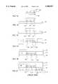
- FIGS. 1A-Hillustrate stages in a conventional method for packaging a semiconductor flip chip, in which a semiconductor die and a packaging substrate are electrically connected and mechanically bonded.
- FIG. 1Ashows a cross-sectional, side view of an unbonded flip chip with the chip 100 having an active circuit surface 102 on which are arranged solder balls 104.
- the soldermay be composed of a low melting point eutectic material or a high lead material, for example. It should be noted that this figure and the figures that follow are intended to be representative and, for example, do not show the solder balls 104 in proportion to the semiconductor die 100.
- solder fluxPrior to bonding the die 100 to a substrate, solder flux is applied to either the active surface 102 of the die 100 or the packaging substrate surface.
- the fluxserves primarily to aid the flow of the solder, such that the solder balls 104 make good contact with traces on the packaging substrate. It may be applied in any of a variety of methods, including brushing or spraying, or dipping the die 100 into a thin film, thereby coating the solder balls 104 with flux.
- the fluxgenerally has an acidic component, which removes oxide barriers from the solder surfaces, and an adhesive quality, which helps to prevent the die from moving on the packaging substrate surface during the assembly process.
- the die 100is aligned with and placed onto a placement site on the packaging substrate 106 such that the die's solder balls 104 are aligned with electrical traces (not shown) on the substrate 106.
- the substrateis typically composed of a laminate or organic material, such as fiber glass, PTFE (such as TeflonTM, available form Gore, Eau Claire, Wis.) BT resin, epoxy laminates or ceramic-plastic composites.
- Heatto a temperature of about 220° C., for example
- the solder balls 104to reflow and form electrical connections between the die 100 and the packaging substrate 106.
- the remaining flux residueis substantially removed in a cleaning step, for instance by washing with an appropriate solvent.
- An underfill materialtypically a thermo-set epoxy 108, such as is available from Hysol Corporation of Industry, California (product numbers 4511 and 4527), Ablestik Laboratories of Rancho Domingo, Calif., and Johnson Matthey Electronics of San Diego, Calif., is dispensed into the remaining space (or "gap") 107 between the die 100 and the substrate 106.
- a bead of thermo-set epoxyis applied along one edge of the die where it is drawn under the die by capillary action until it completely fills the gap between the die and the packaging substrate. Slight heating of the packaging substrate after dispensing of the underfill epoxy assists the flow.
- the underfill epoxy flowis further assisted by vacuum, or, alternatively, by injection of the epoxy into the gap.
- FIG. 1Cshows the semiconductor die 100 interconnected to the packaging substrate 106 electrically by solder 104 joints and mechanically by a cured layer of epoxy 108.
- a stiffener 110may be placed around the die 100 on the substrate 106 where it is bonded with a heat curable adhesive (not shown), as shown in FIG. 1D.
- the stiffener 110is typically a flat piece of high modulus (about 9 ⁇ 10 6 to 30 ⁇ 10 6 psi) metal about 10 to 40 mils thick, having substantially the same dimensions as the package substrate 106 with a window 111 in its center to clear the die 100.
- the stiffener 110is composed of nickel-plated copper which has a coefficient of thermal expansion similar to that of typical substrate 106 materials.
- the stiffener 110may be bonded to the substrate 106 prior to the placement, bonding and underfilling/curing steps previously described, or it may be bonded after the placement and bonding of the die 100, but prior to the underfilling/curing step.
- the stiffeneris typically bonded and cured in a separate step following curing of the underfill material 108.
- the adhesivemay also be cured concurrently with the curing of the underfill material in a single heating step.
- the purpose of the stiffener 110is to constrain the substrate 106 in order to prevent its warpage or other movement relative to the die 100 which may be caused by thermal cycling during operation of an electronic device in which the package is installed. Such movement may result from the different coefficients of thermal expansion (CTE) of the die 100 and substrate 106 materials, and may produce stress in the die or the package as a whole which can result in electrical and mechanical failures.
- CTEcoefficients of thermal expansion
- a heat spreader 112typically composed of a high thermal conductivity (about 2 to 4 W/cm.K) material, and having substantially the same dimensions as the package substrate 106, is attached over the stiffener 110 and the die 100 and bonded to each by a thermally conductive adhesive (not shown) which is also then heat cured.
- a conventional heat spreaderis also typically a flat piece of nickel-plated copper about 20 to 40 mils thick.
- a conventional heat spreader 112may not be applied until the underfill material 108 has been dispensed and cured because the heat spreader 112 prevents access to the die 100. Therefore, the heat spreader 112 is applied in a separate step following attachment of the die 100 and stiffener 110.
- the purpose of the heat spreaderis to disperse the heat generated during thermal cycling in order to reduce stress in the package due to different CTEs of the various elements of the package, including the die 100, substrate 106 and underfill 108. Since it covers and is attached to the die 100, the heat spreader 112 also plays a role is constraining the die 100 in place on the substrate 106, but only once the heat spreader 112 is attached in position following dispensation and curing of the underfill material 108.
- solder balls 116are bonded to the underside 115 of the substrate 106. These solder balls 116 may be used to bond the chip package to a circuit board, such as a mother board, for use in an electronic application.
- a problem with such flip chip package constructionsis that during the heating and cooling involved in curing of the underfill material 108, the different CTEs of the substrate 106 and die 100 materials may stress these materials by causing them to warp or otherwise move relative to each other.
- the epoxy underfill 108typically shrinks during the curing process, applying additional stress on the bonded die 100 and substrate 106 which may cause one or both to warp.
- stress in the semiconductor packagewhich may ultimately result in its electronic and/or mechanical failure, including cracking of the die 100.
- the use of separate stiffener 110 and heat spreader 112 elementsadds two bonding steps to the basic flip-chip packaging process, thereby decreasing production efficiency.
- the present inventionprovides a single-piece integrated heat spreader/stiffener which is bonded to the substrate and die in a semiconductor package following electrical bonding of the die to the substrate, a packaging method using the integrated heat spreader/stiffener, and a semiconductor package incorporating the integrated heat spreader/stiffener.
- the integrated heat spreader/stiffeneris a piece of high modulus (preferably about 9 ⁇ 10 6 to 30 ⁇ 10 6 psi; more preferably about 15 ⁇ 10 6 to 30 ⁇ 10 6 psi, and most preferably about 25 ⁇ 10 6 psi), high thermal conductivity (preferably about 2 to 4 W/cm.K; more preferably about 3 to 4 W/cm.K, and most preferably about 4 W/cm.K) material shaped to attach over a die on the surface of a packaging substrate.
- high moduluspreferably about 9 ⁇ 10 6 to 30 ⁇ 10 6 psi; more preferably about 15 ⁇ 10 6 to 30 ⁇ 10 6 psi, and most preferably about 25 ⁇ 10 6 psi
- high thermal conductivitypreferably about 2 to 4 W/cm.K; more preferably about 3 to 4 W/cm.K, and most preferably about 4 W/cm.K
- the heat spreader/stiffeneris equipped with a plurality of apertures to provide access to the perimeter of the die for dispensation of underfill material between the die and the substrate, and optionally, to the top surface of the die for dispensation of adhesive to bond the heat spreader/stiffener to the die.
- the adhesive and underfill resinsare cured by heating.
- a ball grid array (BGA) processmay then be used to apply solder balls to the underside of the substrate for subsequent bonding of the package to a circuit board for use.
- the present inventionprovides an integrated heat spreader/stiffener for securing a semiconductor die to a packaging substrate.
- the integrated heat spreader/stiffenerincludes a top portion having a plurality of apertures and a circumferential side region attached to the top portion.
- the top portion and the circumferential side regiondefine a cavity in which the top portion is capable of partially covering and the circumferential side region is capable of enclosing a semiconductor die mounted on a packaging substrate, while providing access to a perimeter region of the die through said apertures.
- the integrated heat spreader/stiffeneris capable of attaching to the die and to the packaging substrate to hold the die substantially in place on the substrate, and substantially prevent warpage of the die relative to the substrate.
- the integrated heat spreader/stiffeneris preferably composed of a high modulus and high thermal conductivity material shaped into the top portion and circumferential side region, so that the top portion and circumferential side region together form a unitary structure which defines the cavity.
- the present inventionalso provides a semiconductor package.
- the packageincludes a packaging substrate having a top side and an underside and a semiconductor die having an active surface and a top surface.
- the active surface of the dieis bonded to the top side of the substrate, and an underfill material is between the die and the substrate.
- the packagealso includes an integrated heat spreader/stiffener bonded to the top surface of the die and to the top side of the substrate, the integrated heat spreader/stiffener.
- the integrated heat spreader/stiffenerincludes a top portion having a plurality of apertures and a circumferential side region attached to the top portion.
- the top portion and the circumferential side regiondefine a cavity in which the top portion is capable of partially covering and the circumferential side region is capable of enclosing a semiconductor die mounted on a packaging substrate, while providing access to a perimeter region of the die through said apertures.
- the integrated heat spreader/stiffeneris capable of attaching to the die and to the packaging substrate to hold the die substantially in place on the substrate, and substantially prevent warpage of the die relative to the substrate.
- the integrated heat spreader/stiffeneris preferably composed of a high modulus and high conductivity material shaped into the top portion and circumferential side region, so that the top portion and circumferential side region together form a unitary structure which defines the cavity.
- a semiconductor package according to this preferred embodiment of the present inventionmay also include a solder ball grid array attached to the underside of the substrate.
- the present inventionprovides a method of making a semiconductor flip chip package.
- the methodinvolves providing a packaging substrate having a top side and an underside, electrically bonding a semiconductor die to electrical traces on the top side of the substrate, and bonding an integrated heat spreader/stiffener to the top side of the substrate and to a top surface of the die.
- the integrated heat spreader/stiffenerincludes a top portion having a plurality of apertures and a circumferential side region attached to the top portion.
- the top portion and the circumferential side regiondefine a cavity in which the top portion is capable of partially covering and the circumferential side region is capable of enclosing a semiconductor die mounted on a packaging substrate, while providing access to a perimeter region of the die through said apertures.
- the integrated heat spreader/stiffeneris capable of attaching to the die and to the packaging substrate to hold the die substantially in place on the substrate, and substantially prevent warpage of the die relative to the substrate.
- the integrated heat spreader/stiffeneris attached to the die and to the packaging substrate to hold the die substantially in place on the substrate, and substantially prevent warpage of the die relative to the substrate.
- the integrated heat spreader/stiffeneris preferably composed of a high modulus and high thermal conductivity material shaped into the top portion and circumferential side region, so that the top portion and circumferential side region together form a unitary structure which defines the cavity.
- a method according to this preferred embodiment of the present inventionmay involve dispensing thermal adhesive through one or more apertures in the top portion of the integrated heat spreader/stiffener to the top surface of the die for the die-integrated heat spreader/stiffener bonding step.
- a method according to this preferred embodiment of the present inventionmay also involve attaching a solder ball grid array to the underside of the substrate.
- FIGS. 1A-Fdepict cross-sectional views of stages in the packaging of flip chip devices using a conventional stiffener and heat spreader.
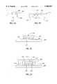
- FIGS. 2A-Fdepict cross-sectional views of stages in the packaging of flip chip devices using an integrated heat spreader/stiffener in accordance with a preferred embodiment of the present invention.
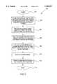
- FIGS. 3depicts a flow chart showing the steps of a method of packaging of flip chip devices using an integrated heat spreader/stiffener in accordance with a preferred embodiment of the present invention.
- FIGS. 4a and 4bare plan views of alternate embodiments of the preferred embodiment of the integrated heat spreader/stiffener of the present invention.
- the present inventionprovides an integrated heat spreader/stiffener for use in semiconductor flip chip packaging as a replacement for the conventional combination of a heat spreader and stiffener, a packaging method using the integrated heat spreader/stiffener, and a semiconductor package incorporating the integrated heat spreader/stiffener.
- the integrated heat spreader/stiffeneris a piece of high modulus, high thermal conductivity material shaped to attach over a die on the surface of a packaging substrate.
- the heat spreader/stiffeneris equipped with a plurality of apertures to provide access to the top surface of the die for adhesive to bond the heat spreader/stiffener to the die, and to its perimeter to provide access for dispensation of underfill material between the die and the substrate.
- a ball grid array (BGA) processmay then be used to apply solder balls to the underside of the substrate for subsequent bonding of the package to a circuit board for use.
- BGAball grid array
- the integrated heat spreader/stiffenermay take may different forms beyond those specifically depicted and described herein, which firmly hold the die to the substrate while providing access to the die top and perimeter during underfill dispensation and cure through apertures in the top of the integrated heat spreader/stiffener.
- FIG. 2Ashows a cross-sectional view of a semiconductor die (flip chip) 200 with solder balls 204 attached to its active surface 202.
- the die 200 and solder balls 204may be of the conventional sort well known to those of skill in the art, and described above.
- FIG. 2Bshows a cross-sectional view of an integrated heat spreader/stiffener in accordance with a preferred embodiment of the present invention.
- the integrated heat spreader/stiffener 210may be composed of any high modulus (preferably about 9 ⁇ 10 6 to 30 ⁇ 10 6 psi; more preferably about 15 ⁇ 10 6 to 30 ⁇ 10 6 psi, and most preferably about 25 ⁇ 10 6 psi), high thermal conductivity (preferably about 2 to 4 W/cm.K; more preferably about 3 to 4 W/cm.K, and most preferably about 4 W/cm.K) material compatible with the manufacture and operation of semiconductor packaging.
- high moduluspreferably about 9 ⁇ 10 6 to 30 ⁇ 10 6 psi; more preferably about 15 ⁇ 10 6 to 30 ⁇ 10 6 psi, and most preferably about 25 ⁇ 10 6 psi
- high thermal conductivitypreferably about 2 to 4 W/cm.K; more preferably about 3 to 4 W/cm.K, and most preferably about 4 W/
- the integrated heat spreader/stiffener 210is composed of a high modulus, high conductivity metal which provides the benefits of the rigidity and the heat dissipation characteristics of conventional stiffeners and heat spreaders, respectively.
- a particularly preferred materialis nickel-plated copper.
- the integrated heat spreader/stiffener 210has top 212 and side 214 portions which surround a cavity 218 designed to accommodate the die 200.
- the cavitymay preferably be about 15.5 to 20 mm long, by about 15.5 to 20 mm wide, by about 0.4 to 0.6 mm deep, more preferably about 16 mm long, by about 16 mm wide, by about 0.5 mm deep.
- FIG. 4ais a plan view of the top portion 212.
- the top portion 212is traversed by apertures 215 and 216, which provide access to the perimeter, and optionally the top, of the die when the integrated heat spreader/stiffener 210 is placed over the die 200.
- the top 212 of the integrated heat spreader/stiffenermay have about 5 substantially evenly distributed apertures.
- the aperturesare round and have a diameter of between about 10 and 50 mils, more preferably about 20 to 40 mils.
- the cavity 218 of the heat spreader/stiffener 210has a depth sufficient to accommodate the height of the die 200 when bonded to the substrate 206.
- the heat spreader/stiffener 210may take a variety of forms adapted to enclose the die 200 as long as there are apertures provided in the top portion to provide access to the die 200.
- the heat spreader/stiffener 210may have a top 212 with a rectilinear or curvilinear profile and any number of aperture patterns which provide access to the top and perimeter of the die 200.
- FIG. 4billustrates an embodiment wherein the top portion 212 is circular.
- solder fluxmay be applied to either the active surface 204 of the die 200 or the packaging substrate 206 surface.
- the fluxmay be applied in any of a variety of methods, including brushing or spraying, or dipping the die 200 into a thin film, thereby coating the solder balls 204 with flux.
- the die 200may be aligned with and placed onto a placement site on the packaging substrate 206 such that the die solder balls 204 are aligned with electrical traces (not shown) on the substrate 206.
- the substratemay be composed of a laminate or organic material, such as fiber glass, PTFE (such as TeflonTM, available form Gore, Eau Claire, Wis.) BT resin, epoxy laminates or ceramic-plastic composites.
- Heat(to a temperature of about 220° C., for example) may be applied to one or more of the die 200 and the packaging substrate 206, causing the solder balls 204 to reflow and form electrical connections between the die 200 and electrical traces (not shown) on the packaging substrate 206. Then, the remaining flux residue is substantially removed in a cleaning step, for instance by washing with an appropriate solvent.
- an integrated heat spreader/stiffener 210is placed over the die 200 for attachment to the top surface 203 of the die 200 and the substrate 206 surface.
- the attachmentis preferably accomplished with a thermally conductive thermal adhesive.
- Such adhesivesare well known to those skilled in the art.
- mechanical attachment meansmay be used to attach the integrated heat spreader/stiffener 210.
- the adhesivemay be applied the to the top 212 of the heat spreader/stiffener 210 within the cavity 218 and the bottom of the heat spreader/stiffener sides 214 which contact the substrate 206.
- the adhesivemay additionally or alternatively be applied to the top surface 203 of the die 200 and the substrate 206 surface at the point where the integrated heat spreader/stiffener 210 contacts the substrate 206.
- the adhesive used to attach the heat spreader/stiffener 210 to the die 200is dispensed through one or more apertures 215 in the top 212 of an integrated heat spreader/stiffener 210 to the interface 217 between the two.
- the adhesive used to attach the integrated heat spreader/stiffener 210 to the die 200, and that used to attach the integrated heat spreader/stiffener 210 to the substrate 206may be the same or different adhesives.
- the adhesiveis cured by heating, for example to a temperature of about 100° to 150° C., once the heat spreader/stiffener 210 is in position.
- an underfill material 208such as a thermo-set epoxy, for example, those available from Hysol Corporation of Industry, California (product numbers 4511 and 4527), Ablestik Laboratories of Rancho Domingo, Calif., and Johnson Matthey Electronics of San Diego, Calif., is dispensed through an aperture or apertures 216 opening onto the perimeter of the die 200 into the remaining space (or "gap") 207 between the die 200 and the substrate 206.
- a thermo-set epoxyfor example, those available from Hysol Corporation of Industry, California (product numbers 4511 and 4527), Ablestik Laboratories of Rancho Domingo, Calif., and Johnson Matthey Electronics of San Diego, Calif.
- thermo-set epoxyis dispensed through a perimeter aperture(s) 216 and collects along one or more edges of the die 200 where it is drawn under the die 200 by capillary action until it fills the gap 207 between the die 200 and the packaging substrate 206. Slight heating of the packaging substrate after dispensing of the underfill epoxy may be used to assist the flow.
- the underfill epoxy 208may be cured by heating the substrate 206 and/or die 200 to an appropriate curing temperature, for example, about 130° to 165° C.
- an appropriate curing temperaturefor example, about 130° to 165° C.
- the mechanical bonding of the die 200 to the substrate by dispensing and curing of the underfill material 208occurs with the die 200 firmly held in place on the substrate 206 by the integrated heat spreader/stiffener 210.
- the dieis prevented from warping or otherwise moving during the curing step, as well as thereafter during operation in its intended application.
- the integrated heat spreader/stiffener of the present inventionis a single piece which replaces the conventional use of a separate stiffener and heat spreader, it provides the additional advantage of eliminating the need for two separate attachment steps, such as are used to attach the conventional apparatuses. As a result, the efficiency of the packaging process is improved.
- the packagemay further be prepared for subsequent attachment to a circuit board by attaching a solder ball grid array 230 to the underside of the packaging substrate 206, as in conventional packaging procedures, as shown in FIG. 2F.
- FIG. 3shows a flow chart 300 of a preferred method of packaging a semiconductor flip chip, in accordance with a preferred embodiment of the present invention.
- the method 300begins at 301, and at a step 302 a semiconductor flip chip (die) with solder balls on its active surface, a packaging substrate and an integrated heat spreader/stiffener (IHS/S) in accordance with the present invention are provided.
- the dieis placed on the substrate, the die and or the substrate having first been coated with flux, as described above, and the substrate and/or die is heated to reflow the solder balls and electrically connect the die to appropriate electrical traces on the substrate.
- an integrated heat spreader/stiffener in accordance with the present inventionis placed over the die and attached to the die and the substrate.
- the IHS/Sis attached using a thermally conductive thermal adhesive.
- the adhesive used to attach the IHS/S to the dieis dispensed through one or more apertures in the top of the IHS/S to the interface between the two.
- an underfill materialsuch as a thermo-set epoxy, is dispensed through an aperture or apertures in the top of the IHS/S opening onto the perimeter of the die into the gap between the die and the substrate, at a step 308.
- the underfill materialis cured at a step 310 by heating the substrate and/or die to an appropriate curing temperature, which may be about 100° to 165° C. for a typical epoxy underfill.
- an appropriate curing temperaturewhich may be about 100° to 165° C. for a typical epoxy underfill.
- the presence of the integrated heat spreader/stiffenerprevents warping or other movement of the die relative to the substrate during and following curing of the underfill material. This decreases the likelihood of package failure resulting from underfill curing, and thus enhances the reliability of the package.
- the packagemay be prepared for subsequent attachment to a circuit board by attaching a solder ball grid array to the underside of the packaging substrate at a step 312. The process is completed at 314.
Landscapes
- Engineering & Computer Science (AREA)
- Computer Hardware Design (AREA)
- Microelectronics & Electronic Packaging (AREA)
- Power Engineering (AREA)
- Physics & Mathematics (AREA)
- Condensed Matter Physics & Semiconductors (AREA)
- General Physics & Mathematics (AREA)
- Manufacturing & Machinery (AREA)
- Cooling Or The Like Of Semiconductors Or Solid State Devices (AREA)
Abstract
Description
Claims (25)
Priority Applications (1)
| Application Number | Priority Date | Filing Date | Title |
|---|---|---|---|
| US08/935,424US5909057A (en) | 1997-09-23 | 1997-09-23 | Integrated heat spreader/stiffener with apertures for semiconductor package |
Applications Claiming Priority (1)
| Application Number | Priority Date | Filing Date | Title |
|---|---|---|---|
| US08/935,424US5909057A (en) | 1997-09-23 | 1997-09-23 | Integrated heat spreader/stiffener with apertures for semiconductor package |
Publications (1)
| Publication Number | Publication Date |
|---|---|
| US5909057Atrue US5909057A (en) | 1999-06-01 |
Family
ID=25467101
Family Applications (1)
| Application Number | Title | Priority Date | Filing Date |
|---|---|---|---|
| US08/935,424Expired - LifetimeUS5909057A (en) | 1997-09-23 | 1997-09-23 | Integrated heat spreader/stiffener with apertures for semiconductor package |
Country Status (1)
| Country | Link |
|---|---|
| US (1) | US5909057A (en) |
Cited By (85)
| Publication number | Priority date | Publication date | Assignee | Title |
|---|---|---|---|---|
| US6051888A (en)* | 1997-04-07 | 2000-04-18 | Texas Instruments Incorporated | Semiconductor package and method for increased thermal dissipation of flip-chip semiconductor package |
| US6222263B1 (en)* | 1999-10-19 | 2001-04-24 | International Business Machines Corporation | Chip assembly with load-bearing lid in thermal contact with the chip |
| US6232652B1 (en)* | 1999-06-08 | 2001-05-15 | Mitsubishi Denki Kabushiki Kaisha | Semiconductor device having a packaged semiconductor element and permanent vent and manufacturing method thereof |
| US6239486B1 (en)* | 1999-04-27 | 2001-05-29 | Fujitsu Limited | Semiconductor device having cap |
| US6255140B1 (en)* | 1998-10-19 | 2001-07-03 | Industrial Technology Research Institute | Flip chip chip-scale package |
| US6294831B1 (en)* | 1998-11-05 | 2001-09-25 | International Business Machines Corporation | Electronic package with bonded structure and method of making |
| US6306751B1 (en) | 1999-09-27 | 2001-10-23 | Lsi Logic Corporation | Apparatus and method for improving ball joints in semiconductor packages |
| US6309908B1 (en) | 1999-12-21 | 2001-10-30 | Motorola, Inc. | Package for an electronic component and a method of making it |
| US6312978B1 (en)* | 2000-01-07 | 2001-11-06 | Ronald Leavitt Law | Method for leadless die interconnect without substrate cavity |
| US6320754B1 (en)* | 1999-08-06 | 2001-11-20 | Agilent Technologies, Inc. | Apparatus for the reduction of interfacial stress caused by differential thermal expansion in an integrated circuit package |
| US6369448B1 (en) | 2000-01-21 | 2002-04-09 | Lsi Logic Corporation | Vertically integrated flip chip semiconductor package |
| EP1202343A2 (en) | 2000-10-23 | 2002-05-02 | Rohm Co., Ltd. | Semiconductor device and fabrication process therefor |
| US6399902B1 (en) | 2000-08-01 | 2002-06-04 | Advanced Micro Devices, Inc. | Inline flux measurement system |
| WO2002027788A3 (en)* | 2000-09-28 | 2002-06-13 | Intel Corp | Structure and process for reducing die corner and edge stresses in microelectronic packages |
| US6410981B2 (en)* | 1997-10-24 | 2002-06-25 | Nec Corporation | Vented semiconductor device package having separate substrate, strengthening ring and cap structures |
| US6426875B1 (en)* | 1999-07-30 | 2002-07-30 | Micron Technology, Inc. | Heat sink chip package |
| US6445062B1 (en)* | 1999-02-19 | 2002-09-03 | Nec Corporation | Semiconductor device having a flip chip cavity with lower stress and method for forming same |
| US6472741B1 (en) | 2001-07-14 | 2002-10-29 | Siliconware Precision Industries Co., Ltd. | Thermally-enhanced stacked-die ball grid array semiconductor package and method of fabricating the same |
| US6514847B1 (en) | 1997-11-28 | 2003-02-04 | Sony Corporation | Method for making a semiconductor device |
| US20030106924A1 (en)* | 2001-01-17 | 2003-06-12 | Kazuhiro Nobori | Electronic circuit device and method for manufacturing the same |
| US6593652B2 (en)* | 2001-03-12 | 2003-07-15 | Rohm Co., Ltd. | Semiconductor device reinforced by a highly elastic member made of a synthetic resin |
| US6614102B1 (en) | 2001-05-04 | 2003-09-02 | Amkor Technology, Inc. | Shielded semiconductor leadframe package |
| US20030189814A1 (en)* | 2002-04-05 | 2003-10-09 | Murata Manufacturing Co., Ltd. | Electronic device |
| EP1076361A3 (en)* | 1999-08-11 | 2003-10-22 | Fujikura Ltd. | Chip assembly module of bump connection type using a multi-layer printed circuit substrate |
| US20030230800A1 (en)* | 2002-05-28 | 2003-12-18 | Fujitsu Limited | Semiconductor device manufacturing method, semiconductor device, and semiconductor device unit |
| US6703704B1 (en) | 2002-09-25 | 2004-03-09 | International Business Machines Corporation | Stress reducing stiffener ring |
| US6707168B1 (en)* | 2001-05-04 | 2004-03-16 | Amkor Technology, Inc. | Shielded semiconductor package with single-sided substrate and method for making the same |
| US20040065964A1 (en)* | 2002-10-02 | 2004-04-08 | Advanced Semiconductor Engineering, Inc. | Semiconductor package with thermal enhance film and manufacturing method thereof |
| US20040075990A1 (en)* | 2002-10-22 | 2004-04-22 | International Business Machines Corporation | Packaging integrated circuits with adhesive posts |
| US20040084763A1 (en)* | 2002-11-05 | 2004-05-06 | Advanced Semiconductor Engineering, Inc. | Thermal enhance package with universal heat spreader |
| US20040112571A1 (en)* | 2002-11-01 | 2004-06-17 | Cooligy, Inc. | Method and apparatus for efficient vertical fluid delivery for cooling a heat producing device |
| US20040119149A1 (en)* | 2002-12-20 | 2004-06-24 | Nokia Corporation | Grounded embedded flip chip RF integrated circuit |
| US6759860B1 (en)* | 2001-06-19 | 2004-07-06 | Lsi Logic Corporation | Semiconductor device package substrate probe fixture |
| US6787899B2 (en)* | 2002-03-12 | 2004-09-07 | Intel Corporation | Electronic assemblies with solidified thixotropic thermal interface material |
| US20040188066A1 (en)* | 2002-11-01 | 2004-09-30 | Cooligy, Inc. | Optimal spreader system, device and method for fluid cooled micro-scaled heat exchange |
| US20040233639A1 (en)* | 2003-01-31 | 2004-11-25 | Cooligy, Inc. | Removeable heat spreader support mechanism and method of manufacturing thereof |
| US6853068B1 (en) | 2002-05-22 | 2005-02-08 | Volterra Semiconductor Corporation | Heatsinking and packaging of integrated circuit chips |
| US20050036291A1 (en)* | 2003-08-12 | 2005-02-17 | Siliconware Precision Industries Co., Ltd. | Semiconductor package with heat dissipating structure |
| US6882041B1 (en)* | 2002-02-05 | 2005-04-19 | Altera Corporation | Thermally enhanced metal capped BGA package |
| US20050127502A1 (en)* | 2003-12-16 | 2005-06-16 | Taiwan Semiconductor Manufacturing Co., Ltd. | Thermal dispensing enhancement for high performance flip chip BGA (HPFCBGA) |
| US20050199998A1 (en)* | 2004-03-09 | 2005-09-15 | Siliconware Precision Industries Co., Ltd. | Semiconductor package with heat sink and method for fabricating the same and stiffener |
| US20050211418A1 (en)* | 2002-11-01 | 2005-09-29 | Cooligy, Inc. | Method and apparatus for efficient vertical fluid delivery for cooling a heat producing device |
| AT413062B (en)* | 2000-07-12 | 2005-10-15 | Tridonic Optoelectronics Gmbh | METHOD FOR PRODUCING A LED LIGHT SOURCE |
| US20050269691A1 (en)* | 2004-06-04 | 2005-12-08 | Cooligy, Inc. | Counter flow micro heat exchanger for optimal performance |
| US20050281011A1 (en)* | 2004-06-22 | 2005-12-22 | Lim Hong T | Heat spreader in integrated circuit package |
| US6979594B1 (en) | 2002-07-19 | 2005-12-27 | Asat Ltd. | Process for manufacturing ball grid array package |
| US6982481B1 (en)* | 2003-10-08 | 2006-01-03 | Nortel Networks Limited | System for dissipating heat and shielding electromagnetic radiation produced by an electronic device |
| US6987032B1 (en) | 2002-07-19 | 2006-01-17 | Asat Ltd. | Ball grid array package and process for manufacturing same |
| WO2005096731A3 (en)* | 2004-03-30 | 2006-02-23 | Honeywell Int Inc | Heat spreader constructions, integrated circuitry, methods of forming heat speader contruictions, and methods of forming integrated circuitry |
| US20060051894A1 (en)* | 2004-09-06 | 2006-03-09 | Advanced Semiconductor Engineering, Inc. | Method for bonding flip chip on leadframe |
| US20060081978A1 (en)* | 2004-10-20 | 2006-04-20 | Siliconware Precision Industries Co., Ltd. | Heat dissipating package structure and method for fabricating the same |
| US20060158208A1 (en)* | 2005-01-14 | 2006-07-20 | Applied Materials, Inc. | Prober tester |
| US20060273454A1 (en)* | 2005-06-06 | 2006-12-07 | Daogiang Lu | Locking mechanism for die assembly |
| US20070175621A1 (en)* | 2006-01-31 | 2007-08-02 | Cooligy, Inc. | Re-workable metallic TIM for efficient heat exchange |
| WO2008003223A1 (en)* | 2006-06-30 | 2008-01-10 | Hong Kong Applied Science And Technology Research Institute Co. Ltd. | Semiconductor package system and method of improving heat dissipation of a semiconductor package |
| CN100378972C (en)* | 2005-03-08 | 2008-04-02 | 台湾积体电路制造股份有限公司 | Heat sink and package using the same |
| US20080116586A1 (en)* | 2006-11-17 | 2008-05-22 | Stats Chippac, Inc. | Methods for manufacturing thermally enhanced flip-chip ball grid arrays |
| US20080296756A1 (en)* | 2007-05-30 | 2008-12-04 | Koch James L | Heat spreader compositions and materials, integrated circuitry, methods of production and uses thereof |
| US20090001555A1 (en)* | 2007-06-26 | 2009-01-01 | Nec Electronics Corporation | Semiconductor device having metal cap |
| US20090096084A1 (en)* | 2007-10-12 | 2009-04-16 | John Peter Karidis | Semiconductor chip packages having reduced stress |
| US20090166830A1 (en)* | 2007-12-28 | 2009-07-02 | Kuan-Hsing Li | Metallic cover of miniaturization module |
| US7616444B2 (en) | 2004-06-04 | 2009-11-10 | Cooligy Inc. | Gimballed attachment for multiple heat exchangers |
| US20090283302A1 (en)* | 2008-05-13 | 2009-11-19 | Samsung Electro-Mechanics Co., Ltd. | Printed circuit board and manufacturing method thereof |
| US20090321923A1 (en)* | 2008-06-30 | 2009-12-31 | Rajasekaran Swaminathan | Magnetic particle-based composite materials for semiconductor packages |
| US20100014254A1 (en)* | 2007-02-27 | 2010-01-21 | Fujitsu Limited | Printed circuit board unit and semiconductor package |
| US20100148347A1 (en)* | 2008-12-16 | 2010-06-17 | Stmicroelectronics, Inc. | Chip scale package structure with can attachment |
| US20100244236A1 (en)* | 2009-03-26 | 2010-09-30 | Yun Jaeun | Integrated circuit packaging system with heat spreader and method of manufacture thereof |
| US7836597B2 (en) | 2002-11-01 | 2010-11-23 | Cooligy Inc. | Method of fabricating high surface to volume ratio structures and their integration in microheat exchangers for liquid cooling system |
| US7913719B2 (en) | 2006-01-30 | 2011-03-29 | Cooligy Inc. | Tape-wrapped multilayer tubing and methods for making the same |
| US8212353B1 (en)* | 2005-11-08 | 2012-07-03 | Altera Corporation | Structure and assembly procedure for low stress thin die flip chip packages designed for low-K Si and thin core substrate |
| US8254422B2 (en) | 2008-08-05 | 2012-08-28 | Cooligy Inc. | Microheat exchanger for laser diode cooling |
| US8464781B2 (en) | 2002-11-01 | 2013-06-18 | Cooligy Inc. | Cooling systems incorporating heat exchangers and thermoelectric layers |
| US8786075B1 (en) | 2012-04-27 | 2014-07-22 | Amkor Technology, Inc. | Electrical circuit with component-accommodating lid |
| CN103985645A (en)* | 2014-05-27 | 2014-08-13 | 无锡必创传感科技有限公司 | Semiconductor packaging piece and manufacturing method thereof |
| US20150084181A1 (en)* | 2013-02-07 | 2015-03-26 | Taiwan Semiconductor Manufacturing Company, Ltd. | 3DIC Package Comprising Perforated Foil Sheet |
| CN104733405A (en)* | 2015-04-15 | 2015-06-24 | 江苏晟芯微电子有限公司 | Pin-type heat-radiating semiconductor packaging structure |
| US20150303127A1 (en)* | 2009-03-05 | 2015-10-22 | Volterra Semiconductor LLC | Chip-Scale Packaging With Protective Heat Spreader |
| EP2884530A3 (en)* | 2013-12-13 | 2015-10-28 | Huawei Technologies Co., Ltd. | Heat sink and heat dissipation system |
| US20170062377A1 (en)* | 2015-08-28 | 2017-03-02 | Texas Instruments Incorporated | Flip chip backside mechanical die grounding techniques |
| WO2018063213A1 (en)* | 2016-09-29 | 2018-04-05 | Intel Corporation | Methods of forming flexure based cooling solutions for package structures |
| US10643920B1 (en)* | 2017-03-24 | 2020-05-05 | Juniper Networks, Inc. | Lid for semiconductor electronic package |
| US10957656B2 (en)* | 2017-09-27 | 2021-03-23 | Intel Corporation | Integrated circuit packages with patterned protective material |
| US11245099B2 (en)* | 2017-06-26 | 2022-02-08 | Boe Technology Group Co., Ltd. | Packaging cover plate, organic light-emitting diode display and manufacturing method therefor |
| CN114203655A (en)* | 2021-11-19 | 2022-03-18 | 苏州浪潮智能科技有限公司 | Chip package structure |
| US11469188B2 (en) | 2020-06-16 | 2022-10-11 | Samsung Electronics Co., Ltd. | Semiconductor package |
Citations (22)
| Publication number | Priority date | Publication date | Assignee | Title |
|---|---|---|---|---|
| US4004195A (en)* | 1975-05-12 | 1977-01-18 | Rca Corporation | Heat-sink assembly for high-power stud-mounted semiconductor device |
| JPS5721845A (en)* | 1980-07-15 | 1982-02-04 | Nec Corp | Mounting structure for miniaturized electronic parts |
| US4323914A (en)* | 1979-02-01 | 1982-04-06 | International Business Machines Corporation | Heat transfer structure for integrated circuit package |
| JPS61248451A (en)* | 1985-04-26 | 1986-11-05 | Hitachi Ltd | Package sealing structure for semiconductor devices |
| JPH0228351A (en)* | 1988-07-18 | 1990-01-30 | Hitachi Ltd | Semiconductor device |
| JPH0382144A (en)* | 1989-08-25 | 1991-04-08 | Hitachi Ltd | Sealing structure of semiconductor devices |
| US5006922A (en)* | 1990-02-14 | 1991-04-09 | Motorola, Inc. | Packaged semiconductor device having a low cost ceramic PGA package |
| US5019673A (en)* | 1990-08-22 | 1991-05-28 | Motorola, Inc. | Flip-chip package for integrated circuits |
| JPH03236249A (en)* | 1990-02-14 | 1991-10-22 | Shinko Electric Ind Co Ltd | Semiconductor chip module |
| US5103292A (en)* | 1989-11-29 | 1992-04-07 | Olin Corporation | Metal pin grid array package |
| US5291064A (en)* | 1991-04-16 | 1994-03-01 | Nec Corporation | Package structure for semiconductor device having a flexible wiring circuit member spaced from the package casing |
| US5311059A (en)* | 1992-01-24 | 1994-05-10 | Motorola, Inc. | Backplane grounding for flip-chip integrated circuit |
| US5371404A (en)* | 1993-02-04 | 1994-12-06 | Motorola, Inc. | Thermally conductive integrated circuit package with radio frequency shielding |
| US5409865A (en)* | 1993-09-03 | 1995-04-25 | Advanced Semiconductor Assembly Technology | Process for assembling a TAB grid array package for an integrated circuit |
| US5525835A (en)* | 1991-08-08 | 1996-06-11 | Sumitomo Electric Industries, Ltd. | Semiconductor chip module having an electrically insulative thermally conductive thermal dissipator directly in contact with the semiconductor element |
| US5561323A (en)* | 1994-01-28 | 1996-10-01 | International Business Machines Corporation | Electronic package with thermally conductive support member having a thin circuitized substrate and semiconductor device bonded thereto |
| US5570272A (en)* | 1993-08-18 | 1996-10-29 | Lsi Logic Corporation | Apparatus for encapsulating an integrated circuit package |
| US5572070A (en)* | 1995-02-06 | 1996-11-05 | Rjr Polymers, Inc. | Integrated circuit packages with heat dissipation for high current load |
| US5721451A (en)* | 1996-12-02 | 1998-02-24 | Motorola, Inc. | Integrated circuit assembly adhesive and method thereof |
| US5737191A (en)* | 1995-04-07 | 1998-04-07 | Shinko Electric Industries Co., Ltd. | Structure and process for mounting semiconductor chip |
| US5744863A (en)* | 1994-07-11 | 1998-04-28 | International Business Machines Corporation | Chip carrier modules with heat sinks attached by flexible-epoxy |
| US5789809A (en)* | 1995-08-22 | 1998-08-04 | National Semiconductor Corporation | Thermally enhanced micro-ball grid array package |
- 1997
- 1997-09-23USUS08/935,424patent/US5909057A/ennot_activeExpired - Lifetime
Patent Citations (22)
| Publication number | Priority date | Publication date | Assignee | Title |
|---|---|---|---|---|
| US4004195A (en)* | 1975-05-12 | 1977-01-18 | Rca Corporation | Heat-sink assembly for high-power stud-mounted semiconductor device |
| US4323914A (en)* | 1979-02-01 | 1982-04-06 | International Business Machines Corporation | Heat transfer structure for integrated circuit package |
| JPS5721845A (en)* | 1980-07-15 | 1982-02-04 | Nec Corp | Mounting structure for miniaturized electronic parts |
| JPS61248451A (en)* | 1985-04-26 | 1986-11-05 | Hitachi Ltd | Package sealing structure for semiconductor devices |
| JPH0228351A (en)* | 1988-07-18 | 1990-01-30 | Hitachi Ltd | Semiconductor device |
| JPH0382144A (en)* | 1989-08-25 | 1991-04-08 | Hitachi Ltd | Sealing structure of semiconductor devices |
| US5103292A (en)* | 1989-11-29 | 1992-04-07 | Olin Corporation | Metal pin grid array package |
| US5006922A (en)* | 1990-02-14 | 1991-04-09 | Motorola, Inc. | Packaged semiconductor device having a low cost ceramic PGA package |
| JPH03236249A (en)* | 1990-02-14 | 1991-10-22 | Shinko Electric Ind Co Ltd | Semiconductor chip module |
| US5019673A (en)* | 1990-08-22 | 1991-05-28 | Motorola, Inc. | Flip-chip package for integrated circuits |
| US5291064A (en)* | 1991-04-16 | 1994-03-01 | Nec Corporation | Package structure for semiconductor device having a flexible wiring circuit member spaced from the package casing |
| US5525835A (en)* | 1991-08-08 | 1996-06-11 | Sumitomo Electric Industries, Ltd. | Semiconductor chip module having an electrically insulative thermally conductive thermal dissipator directly in contact with the semiconductor element |
| US5311059A (en)* | 1992-01-24 | 1994-05-10 | Motorola, Inc. | Backplane grounding for flip-chip integrated circuit |
| US5371404A (en)* | 1993-02-04 | 1994-12-06 | Motorola, Inc. | Thermally conductive integrated circuit package with radio frequency shielding |
| US5570272A (en)* | 1993-08-18 | 1996-10-29 | Lsi Logic Corporation | Apparatus for encapsulating an integrated circuit package |
| US5409865A (en)* | 1993-09-03 | 1995-04-25 | Advanced Semiconductor Assembly Technology | Process for assembling a TAB grid array package for an integrated circuit |
| US5561323A (en)* | 1994-01-28 | 1996-10-01 | International Business Machines Corporation | Electronic package with thermally conductive support member having a thin circuitized substrate and semiconductor device bonded thereto |
| US5744863A (en)* | 1994-07-11 | 1998-04-28 | International Business Machines Corporation | Chip carrier modules with heat sinks attached by flexible-epoxy |
| US5572070A (en)* | 1995-02-06 | 1996-11-05 | Rjr Polymers, Inc. | Integrated circuit packages with heat dissipation for high current load |
| US5737191A (en)* | 1995-04-07 | 1998-04-07 | Shinko Electric Industries Co., Ltd. | Structure and process for mounting semiconductor chip |
| US5789809A (en)* | 1995-08-22 | 1998-08-04 | National Semiconductor Corporation | Thermally enhanced micro-ball grid array package |
| US5721451A (en)* | 1996-12-02 | 1998-02-24 | Motorola, Inc. | Integrated circuit assembly adhesive and method thereof |
Cited By (142)
| Publication number | Priority date | Publication date | Assignee | Title |
|---|---|---|---|---|
| US6051888A (en)* | 1997-04-07 | 2000-04-18 | Texas Instruments Incorporated | Semiconductor package and method for increased thermal dissipation of flip-chip semiconductor package |
| US6410981B2 (en)* | 1997-10-24 | 2002-06-25 | Nec Corporation | Vented semiconductor device package having separate substrate, strengthening ring and cap structures |
| US6514847B1 (en) | 1997-11-28 | 2003-02-04 | Sony Corporation | Method for making a semiconductor device |
| US6255140B1 (en)* | 1998-10-19 | 2001-07-03 | Industrial Technology Research Institute | Flip chip chip-scale package |
| US6294831B1 (en)* | 1998-11-05 | 2001-09-25 | International Business Machines Corporation | Electronic package with bonded structure and method of making |
| US6562662B2 (en)* | 1998-11-05 | 2003-05-13 | International Business Machines Corporation | Electronic package with bonded structure and method of making |
| US6445062B1 (en)* | 1999-02-19 | 2002-09-03 | Nec Corporation | Semiconductor device having a flip chip cavity with lower stress and method for forming same |
| US6239486B1 (en)* | 1999-04-27 | 2001-05-29 | Fujitsu Limited | Semiconductor device having cap |
| US6232652B1 (en)* | 1999-06-08 | 2001-05-15 | Mitsubishi Denki Kabushiki Kaisha | Semiconductor device having a packaged semiconductor element and permanent vent and manufacturing method thereof |
| US6563712B2 (en) | 1999-07-30 | 2003-05-13 | Micron Technology, Inc. | Heak sink chip package |
| US6493229B2 (en) | 1999-07-30 | 2002-12-10 | Micron Technology, Inc. | Heat sink chip package |
| US6426875B1 (en)* | 1999-07-30 | 2002-07-30 | Micron Technology, Inc. | Heat sink chip package |
| US6320754B1 (en)* | 1999-08-06 | 2001-11-20 | Agilent Technologies, Inc. | Apparatus for the reduction of interfacial stress caused by differential thermal expansion in an integrated circuit package |
| EP1076361A3 (en)* | 1999-08-11 | 2003-10-22 | Fujikura Ltd. | Chip assembly module of bump connection type using a multi-layer printed circuit substrate |
| US6306751B1 (en) | 1999-09-27 | 2001-10-23 | Lsi Logic Corporation | Apparatus and method for improving ball joints in semiconductor packages |
| US6222263B1 (en)* | 1999-10-19 | 2001-04-24 | International Business Machines Corporation | Chip assembly with load-bearing lid in thermal contact with the chip |
| US6309908B1 (en) | 1999-12-21 | 2001-10-30 | Motorola, Inc. | Package for an electronic component and a method of making it |
| US6312978B1 (en)* | 2000-01-07 | 2001-11-06 | Ronald Leavitt Law | Method for leadless die interconnect without substrate cavity |
| US6369448B1 (en) | 2000-01-21 | 2002-04-09 | Lsi Logic Corporation | Vertically integrated flip chip semiconductor package |
| US6558978B1 (en) | 2000-01-21 | 2003-05-06 | Lsi Logic Corporation | Chip-over-chip integrated circuit package |
| AT413062B (en)* | 2000-07-12 | 2005-10-15 | Tridonic Optoelectronics Gmbh | METHOD FOR PRODUCING A LED LIGHT SOURCE |
| US6399902B1 (en) | 2000-08-01 | 2002-06-04 | Advanced Micro Devices, Inc. | Inline flux measurement system |
| WO2002027788A3 (en)* | 2000-09-28 | 2002-06-13 | Intel Corp | Structure and process for reducing die corner and edge stresses in microelectronic packages |
| US6617682B1 (en) | 2000-09-28 | 2003-09-09 | Intel Corporation | Structure for reducing die corner and edge stresses in microelectronic packages |
| US6794223B2 (en) | 2000-09-28 | 2004-09-21 | Intel Corporation | Structure and process for reducing die corner and edge stresses in microelectronic packages |
| US20040087061A1 (en)* | 2000-09-28 | 2004-05-06 | Qing Ma | Structure and process for reducing die corner and edge stresses in microelectronic packages |
| US20050242445A1 (en)* | 2000-10-23 | 2005-11-03 | Kazutaka Shibata | Semiconductor device and fabrication process therefor |
| EP1202343A2 (en) | 2000-10-23 | 2002-05-02 | Rohm Co., Ltd. | Semiconductor device and fabrication process therefor |
| US6936499B2 (en) | 2000-10-23 | 2005-08-30 | Rohm Co., Ltd. | Semiconductor device and fabrication process therefor |
| US20030199120A1 (en)* | 2000-10-23 | 2003-10-23 | Kazutaka Shibata | Semiconductor device and fabrication process therefor |
| EP1202343A3 (en)* | 2000-10-23 | 2004-09-15 | Rohm Co., Ltd. | Semiconductor device and fabrication process therefor |
| US7192870B2 (en) | 2000-10-23 | 2007-03-20 | Rohm Co., Ltd. | Semiconductor device and fabrication process therefor |
| US7208833B2 (en) | 2001-01-17 | 2007-04-24 | Matsushita Electric Industrial Co., Ltd. | Electronic circuit device having circuit board electrically connected to semiconductor element via metallic plate |
| US6943443B2 (en)* | 2001-01-17 | 2005-09-13 | Matsushita Electric Industrial Co., Ltd. | Electronic circuit device including metallic member having installation members |
| US20050148237A1 (en)* | 2001-01-17 | 2005-07-07 | Kazuhiro Nobori | Electronic circuit device |
| US20030106924A1 (en)* | 2001-01-17 | 2003-06-12 | Kazuhiro Nobori | Electronic circuit device and method for manufacturing the same |
| US6593652B2 (en)* | 2001-03-12 | 2003-07-15 | Rohm Co., Ltd. | Semiconductor device reinforced by a highly elastic member made of a synthetic resin |
| US6707168B1 (en)* | 2001-05-04 | 2004-03-16 | Amkor Technology, Inc. | Shielded semiconductor package with single-sided substrate and method for making the same |
| US6614102B1 (en) | 2001-05-04 | 2003-09-02 | Amkor Technology, Inc. | Shielded semiconductor leadframe package |
| US6716676B2 (en) | 2001-06-04 | 2004-04-06 | Siliconware Precision Industries Co., Ltd. | Thermally-enhanced stacked-die ball grid array semiconductor package and method of fabricating the same |
| US6759860B1 (en)* | 2001-06-19 | 2004-07-06 | Lsi Logic Corporation | Semiconductor device package substrate probe fixture |
| US6472741B1 (en) | 2001-07-14 | 2002-10-29 | Siliconware Precision Industries Co., Ltd. | Thermally-enhanced stacked-die ball grid array semiconductor package and method of fabricating the same |
| US6882041B1 (en)* | 2002-02-05 | 2005-04-19 | Altera Corporation | Thermally enhanced metal capped BGA package |
| US6787899B2 (en)* | 2002-03-12 | 2004-09-07 | Intel Corporation | Electronic assemblies with solidified thixotropic thermal interface material |
| US7169650B2 (en) | 2002-03-12 | 2007-01-30 | Intel Corporation | Semi-solid metal injection methods for electronic assembly thermal interface |
| US20050006757A1 (en)* | 2002-03-12 | 2005-01-13 | Intel Corporation | Semi-solid metal injection methods and apparatus for electronic assembly thermal interface |
| US20030189814A1 (en)* | 2002-04-05 | 2003-10-09 | Murata Manufacturing Co., Ltd. | Electronic device |
| CN100456471C (en)* | 2002-04-05 | 2009-01-28 | 株式会社村田制作所 | electronic device |
| US6826053B2 (en)* | 2002-04-05 | 2004-11-30 | Murata Manufacturing Co., Ltd | Electronic device |
| US6853068B1 (en) | 2002-05-22 | 2005-02-08 | Volterra Semiconductor Corporation | Heatsinking and packaging of integrated circuit chips |
| US20030230800A1 (en)* | 2002-05-28 | 2003-12-18 | Fujitsu Limited | Semiconductor device manufacturing method, semiconductor device, and semiconductor device unit |
| US6828676B2 (en)* | 2002-05-28 | 2004-12-07 | Fujitsu Limited | Semiconductor device manufacturing method, semiconductor device, and semiconductor device unit |
| US20060223229A1 (en)* | 2002-07-19 | 2006-10-05 | Asat Ltd. | Ball grid array package and process for manufacturing same |
| US6979594B1 (en) | 2002-07-19 | 2005-12-27 | Asat Ltd. | Process for manufacturing ball grid array package |
| US6987032B1 (en) | 2002-07-19 | 2006-01-17 | Asat Ltd. | Ball grid array package and process for manufacturing same |
| US7371610B1 (en) | 2002-07-19 | 2008-05-13 | Asat Ltd. | Process for fabricating an integrated circuit package with reduced mold warping |
| US6703704B1 (en) | 2002-09-25 | 2004-03-09 | International Business Machines Corporation | Stress reducing stiffener ring |
| US20040065964A1 (en)* | 2002-10-02 | 2004-04-08 | Advanced Semiconductor Engineering, Inc. | Semiconductor package with thermal enhance film and manufacturing method thereof |
| US7094966B2 (en) | 2002-10-22 | 2006-08-22 | International Business Machines Corporation | Packaging integrated circuits with adhesive posts |
| US20040075990A1 (en)* | 2002-10-22 | 2004-04-22 | International Business Machines Corporation | Packaging integrated circuits with adhesive posts |
| US8464781B2 (en) | 2002-11-01 | 2013-06-18 | Cooligy Inc. | Cooling systems incorporating heat exchangers and thermoelectric layers |
| US20050211418A1 (en)* | 2002-11-01 | 2005-09-29 | Cooligy, Inc. | Method and apparatus for efficient vertical fluid delivery for cooling a heat producing device |
| US20040188066A1 (en)* | 2002-11-01 | 2004-09-30 | Cooligy, Inc. | Optimal spreader system, device and method for fluid cooled micro-scaled heat exchange |
| US7836597B2 (en) | 2002-11-01 | 2010-11-23 | Cooligy Inc. | Method of fabricating high surface to volume ratio structures and their integration in microheat exchangers for liquid cooling system |
| US20040112571A1 (en)* | 2002-11-01 | 2004-06-17 | Cooligy, Inc. | Method and apparatus for efficient vertical fluid delivery for cooling a heat producing device |
| US20040084763A1 (en)* | 2002-11-05 | 2004-05-06 | Advanced Semiconductor Engineering, Inc. | Thermal enhance package with universal heat spreader |
| US7224057B2 (en)* | 2002-11-05 | 2007-05-29 | Advanced Semiconductor Engineering, Inc. | Thermal enhance package with universal heat spreader |
| US20040119149A1 (en)* | 2002-12-20 | 2004-06-24 | Nokia Corporation | Grounded embedded flip chip RF integrated circuit |
| US6909169B2 (en)* | 2002-12-20 | 2005-06-21 | Nokia Corporation | Grounded embedded flip chip RF integrated circuit |
| US20040233639A1 (en)* | 2003-01-31 | 2004-11-25 | Cooligy, Inc. | Removeable heat spreader support mechanism and method of manufacturing thereof |
| US6980438B2 (en) | 2003-08-12 | 2005-12-27 | Siliconware Precision Industries Co., Ltd. | Semiconductor package with heat dissipating structure |
| US20050036291A1 (en)* | 2003-08-12 | 2005-02-17 | Siliconware Precision Industries Co., Ltd. | Semiconductor package with heat dissipating structure |
| US6982481B1 (en)* | 2003-10-08 | 2006-01-03 | Nortel Networks Limited | System for dissipating heat and shielding electromagnetic radiation produced by an electronic device |
| US20050127502A1 (en)* | 2003-12-16 | 2005-06-16 | Taiwan Semiconductor Manufacturing Co., Ltd. | Thermal dispensing enhancement for high performance flip chip BGA (HPFCBGA) |
| US7026711B2 (en) | 2003-12-16 | 2006-04-11 | Taiwan Semiconductor Manufacturing Company, Ltd. | Thermal dispensing enhancement for high performance flip chip BGA (HPFCBGA) |
| US20050199998A1 (en)* | 2004-03-09 | 2005-09-15 | Siliconware Precision Industries Co., Ltd. | Semiconductor package with heat sink and method for fabricating the same and stiffener |
| US20090027857A1 (en)* | 2004-03-30 | 2009-01-29 | Dean Nancy F | Heat spreader constructions, intergrated circuitry, methods of forming heat spreader constructions, and methods of forming integrated circuitry |
| WO2005096731A3 (en)* | 2004-03-30 | 2006-02-23 | Honeywell Int Inc | Heat spreader constructions, integrated circuitry, methods of forming heat speader contruictions, and methods of forming integrated circuitry |
| US20050269691A1 (en)* | 2004-06-04 | 2005-12-08 | Cooligy, Inc. | Counter flow micro heat exchanger for optimal performance |
| US7616444B2 (en) | 2004-06-04 | 2009-11-10 | Cooligy Inc. | Gimballed attachment for multiple heat exchangers |
| US7420809B2 (en)* | 2004-06-22 | 2008-09-02 | Lsi Corporation | Heat spreader in integrated circuit package |
| US20050281011A1 (en)* | 2004-06-22 | 2005-12-22 | Lim Hong T | Heat spreader in integrated circuit package |
| US20060051894A1 (en)* | 2004-09-06 | 2006-03-09 | Advanced Semiconductor Engineering, Inc. | Method for bonding flip chip on leadframe |
| US20060081978A1 (en)* | 2004-10-20 | 2006-04-20 | Siliconware Precision Industries Co., Ltd. | Heat dissipating package structure and method for fabricating the same |
| US20100041181A1 (en)* | 2004-10-20 | 2010-02-18 | Siliconware Precision Industries Co., Ltd. | Heat dissipating package structure and method for fabricating the same |
| US7745262B2 (en)* | 2004-10-20 | 2010-06-29 | Siliconware Precision Industries Co., Ltd. | Heat dissipating package structure and method for fabricating the same |
| US7615862B2 (en)* | 2004-10-20 | 2009-11-10 | Siliconware Precision Industries Co., Ltd. | Heat dissipating package structure and method for fabricating the same |
| US20060158208A1 (en)* | 2005-01-14 | 2006-07-20 | Applied Materials, Inc. | Prober tester |
| CN100378972C (en)* | 2005-03-08 | 2008-04-02 | 台湾积体电路制造股份有限公司 | Heat sink and package using the same |
| US20060273454A1 (en)* | 2005-06-06 | 2006-12-07 | Daogiang Lu | Locking mechanism for die assembly |
| US8212353B1 (en)* | 2005-11-08 | 2012-07-03 | Altera Corporation | Structure and assembly procedure for low stress thin die flip chip packages designed for low-K Si and thin core substrate |
| US7913719B2 (en) | 2006-01-30 | 2011-03-29 | Cooligy Inc. | Tape-wrapped multilayer tubing and methods for making the same |
| US20070175621A1 (en)* | 2006-01-31 | 2007-08-02 | Cooligy, Inc. | Re-workable metallic TIM for efficient heat exchange |
| WO2008003223A1 (en)* | 2006-06-30 | 2008-01-10 | Hong Kong Applied Science And Technology Research Institute Co. Ltd. | Semiconductor package system and method of improving heat dissipation of a semiconductor package |
| US20080116586A1 (en)* | 2006-11-17 | 2008-05-22 | Stats Chippac, Inc. | Methods for manufacturing thermally enhanced flip-chip ball grid arrays |
| US8115301B2 (en)* | 2006-11-17 | 2012-02-14 | Stats Chippac, Inc. | Methods for manufacturing thermally enhanced flip-chip ball grid arrays |
| US20100014254A1 (en)* | 2007-02-27 | 2010-01-21 | Fujitsu Limited | Printed circuit board unit and semiconductor package |
| US8023268B2 (en)* | 2007-02-27 | 2011-09-20 | Fujitsu Limited | Printed circuit board unit and semiconductor package |
| US20080296756A1 (en)* | 2007-05-30 | 2008-12-04 | Koch James L | Heat spreader compositions and materials, integrated circuitry, methods of production and uses thereof |
| US20090001555A1 (en)* | 2007-06-26 | 2009-01-01 | Nec Electronics Corporation | Semiconductor device having metal cap |
| US8076771B2 (en)* | 2007-06-26 | 2011-12-13 | Renesas Electronics Corporation | Semiconductor device having metal cap divided by slit |
| US20090096084A1 (en)* | 2007-10-12 | 2009-04-16 | John Peter Karidis | Semiconductor chip packages having reduced stress |
| US7842552B2 (en)* | 2007-10-12 | 2010-11-30 | International Business Machines Corporation | Semiconductor chip packages having reduced stress |
| US20110068462A1 (en)* | 2007-10-12 | 2011-03-24 | International Business Machines Corporation | Semiconductor chip packages having reduced stress |
| US7787250B2 (en)* | 2007-12-28 | 2010-08-31 | Universal Scientific Industrial (Shanghai) Co., Ltd. | Metallic cover of miniaturization module |
| US20090166830A1 (en)* | 2007-12-28 | 2009-07-02 | Kuan-Hsing Li | Metallic cover of miniaturization module |
| US20090283302A1 (en)* | 2008-05-13 | 2009-11-19 | Samsung Electro-Mechanics Co., Ltd. | Printed circuit board and manufacturing method thereof |
| US8222730B2 (en) | 2008-06-30 | 2012-07-17 | Intel Corporation | Magnetic particle-based composite materials for semiconductor packages |
| US20090321923A1 (en)* | 2008-06-30 | 2009-12-31 | Rajasekaran Swaminathan | Magnetic particle-based composite materials for semiconductor packages |
| US7906376B2 (en)* | 2008-06-30 | 2011-03-15 | Intel Corporation | Magnetic particle-based composite materials for semiconductor packages |
| US20110127663A1 (en)* | 2008-06-30 | 2011-06-02 | Rajasekaran Swaminathan | Magnetic particle-based composite materials for semiconductor packages |
| US8299604B2 (en) | 2008-08-05 | 2012-10-30 | Cooligy Inc. | Bonded metal and ceramic plates for thermal management of optical and electronic devices |
| US8254422B2 (en) | 2008-08-05 | 2012-08-28 | Cooligy Inc. | Microheat exchanger for laser diode cooling |
| US20100148347A1 (en)* | 2008-12-16 | 2010-06-17 | Stmicroelectronics, Inc. | Chip scale package structure with can attachment |
| US8389335B2 (en) | 2008-12-16 | 2013-03-05 | Stmicroelectronics Asia Pacific Pte Ltd | Chip Scale Package structure with can attachment |
| US8164179B2 (en)* | 2008-12-16 | 2012-04-24 | STMicroelectronics Asia Pacific PTE Ltd-Singapore | Chip scale package structure with can attachment |
| US20150303127A1 (en)* | 2009-03-05 | 2015-10-22 | Volterra Semiconductor LLC | Chip-Scale Packaging With Protective Heat Spreader |
| US9806001B2 (en)* | 2009-03-05 | 2017-10-31 | Volterra Semiconductor LLC | Chip-scale packaging with protective heat spreader |
| US8415204B2 (en)* | 2009-03-26 | 2013-04-09 | Stats Chippac Ltd. | Integrated circuit packaging system with heat spreader and method of manufacture thereof |
| US20100244236A1 (en)* | 2009-03-26 | 2010-09-30 | Yun Jaeun | Integrated circuit packaging system with heat spreader and method of manufacture thereof |
| US8786075B1 (en) | 2012-04-27 | 2014-07-22 | Amkor Technology, Inc. | Electrical circuit with component-accommodating lid |
| US10685854B2 (en) | 2013-02-07 | 2020-06-16 | Taiwan Semiconductor Manufacturing Company, Ltd. | 3DIC package comprising perforated foil sheet |
| US9653374B2 (en)* | 2013-02-07 | 2017-05-16 | Taiwan Semiconductor Manufacturing Company, Ltd. | 3DIC package comprising perforated foil sheet |
| US11257690B2 (en) | 2013-02-07 | 2022-02-22 | Taiwan Semiconductor Manufacturing Company, Ltd. | 3DIC package comprising perforated foil sheet |
| US20150084181A1 (en)* | 2013-02-07 | 2015-03-26 | Taiwan Semiconductor Manufacturing Company, Ltd. | 3DIC Package Comprising Perforated Foil Sheet |
| EP2884530A3 (en)* | 2013-12-13 | 2015-10-28 | Huawei Technologies Co., Ltd. | Heat sink and heat dissipation system |
| US9462673B2 (en) | 2013-12-13 | 2016-10-04 | Huawei Technologies Co., Ltd. | Heat sink and heat dissipation system |
| CN103985645A (en)* | 2014-05-27 | 2014-08-13 | 无锡必创传感科技有限公司 | Semiconductor packaging piece and manufacturing method thereof |
| CN103985645B (en)* | 2014-05-27 | 2017-02-15 | 无锡必创传感科技有限公司 | Semiconductor packaging piece and manufacturing method thereof |
| CN104733405A (en)* | 2015-04-15 | 2015-06-24 | 江苏晟芯微电子有限公司 | Pin-type heat-radiating semiconductor packaging structure |
| US10600753B2 (en)* | 2015-08-28 | 2020-03-24 | Texas Instruments Incorporated | Flip chip backside mechanical die grounding techniques |
| US20170062377A1 (en)* | 2015-08-28 | 2017-03-02 | Texas Instruments Incorporated | Flip chip backside mechanical die grounding techniques |
| US11574887B2 (en) | 2015-08-28 | 2023-02-07 | Texas Instruments Incorporated | Flip chip backside mechanical die grounding techniques |
| WO2018063213A1 (en)* | 2016-09-29 | 2018-04-05 | Intel Corporation | Methods of forming flexure based cooling solutions for package structures |
| US11276625B2 (en) | 2016-09-29 | 2022-03-15 | Intel Corporation | Methods of forming flexure based cooling solutions for package structures |
| US10643920B1 (en)* | 2017-03-24 | 2020-05-05 | Juniper Networks, Inc. | Lid for semiconductor electronic package |
| US10872838B1 (en)* | 2017-03-24 | 2020-12-22 | Juniper Networks, Inc. | Lid for semiconductor electronic package |
| US11245099B2 (en)* | 2017-06-26 | 2022-02-08 | Boe Technology Group Co., Ltd. | Packaging cover plate, organic light-emitting diode display and manufacturing method therefor |
| US10957656B2 (en)* | 2017-09-27 | 2021-03-23 | Intel Corporation | Integrated circuit packages with patterned protective material |
| US11469188B2 (en) | 2020-06-16 | 2022-10-11 | Samsung Electronics Co., Ltd. | Semiconductor package |
| CN114203655A (en)* | 2021-11-19 | 2022-03-18 | 苏州浪潮智能科技有限公司 | Chip package structure |
| CN114203655B (en)* | 2021-11-19 | 2023-11-03 | 苏州浪潮智能科技有限公司 | Chip packaging structure |
Similar Documents
| Publication | Publication Date | Title |
|---|---|---|
| US5909057A (en) | Integrated heat spreader/stiffener with apertures for semiconductor package | |
| US6166434A (en) | Die clip assembly for semiconductor package | |
| US6724080B1 (en) | Heat sink with elevated heat spreader lid | |
| US6002171A (en) | Integrated heat spreader/stiffener assembly and method of assembly for semiconductor package | |
| US6949404B1 (en) | Flip chip package with warpage control | |
| US6294840B1 (en) | Dual-thickness solder mask in integrated circuit package | |
| EP0684644B1 (en) | Method for manufacturing bump leaded film carrier type semiconductor device | |
| CN1147928C (en) | Semiconductor device having sub-chip-scale package structure and method for forming same | |
| JP3679786B2 (en) | Manufacturing method of semiconductor device | |
| US6486562B1 (en) | Circuit device with bonding strength improved and method of manufacturing the same | |
| JP4703556B2 (en) | Method of attaching flip chip to electrical substrate, flip chip assembly and method of forming underfill coated wafer | |
| KR100384260B1 (en) | Semiconductor device and manufacturing method of the same | |
| KR100394809B1 (en) | Semiconductor package and method for manufacturing the same | |
| KR100532179B1 (en) | Chip scale ball grid array for integrated circuit package | |
| US7741160B1 (en) | Structure and assembly procedure for low stress thin die flip chip packages designed for low-K Si and thin core substrate | |
| TWI415235B (en) | Semiconductor device and manufacturing method thereof | |
| US7148560B2 (en) | IC chip package structure and underfill process | |
| US6756684B2 (en) | Flip-chip ball grid array semiconductor package with heat-dissipating device and method for fabricating the same | |
| KR100442695B1 (en) | Method for manufacturing flip chip package devices with heat spreaders | |
| US20020140085A1 (en) | Semiconductor package including passive elements and method of manufacture | |
| US8174114B2 (en) | Semiconductor package structure with constraint stiffener for cleaning and underfilling efficiency | |
| US6773958B1 (en) | Integrated assembly-underfill flip chip process | |
| JP2001352021A (en) | Semiconductor package, mounting structure and manufacturing method therefor | |
| KR100608610B1 (en) | Printed circuit board, manufacturing method thereof and semiconductor package using same | |
| EP1369919A1 (en) | Flip chip package |
Legal Events
| Date | Code | Title | Description |
|---|---|---|---|
| AS | Assignment | Owner name:LSI LOGIC CORPORATION, CALIFORNIA Free format text:ASSIGNMENT OF ASSIGNORS INTEREST;ASSIGNORS:MCCORMICK, JOHN P.;PATEL, SUNIL A.;REEL/FRAME:008818/0425;SIGNING DATES FROM 19970919 TO 19970922 | |
| STCF | Information on status: patent grant | Free format text:PATENTED CASE | |
| FPAY | Fee payment | Year of fee payment:4 | |
| FPAY | Fee payment | Year of fee payment:8 | |
| SULP | Surcharge for late payment | Year of fee payment:7 | |
| FEPP | Fee payment procedure | Free format text:PAYOR NUMBER ASSIGNED (ORIGINAL EVENT CODE: ASPN); ENTITY STATUS OF PATENT OWNER: LARGE ENTITY Free format text:PAYER NUMBER DE-ASSIGNED (ORIGINAL EVENT CODE: RMPN); ENTITY STATUS OF PATENT OWNER: LARGE ENTITY | |
| FPAY | Fee payment | Year of fee payment:12 | |
| AS | Assignment | Owner name:DEUTSCHE BANK AG NEW YORK BRANCH, AS COLLATERAL AG Free format text:PATENT SECURITY AGREEMENT;ASSIGNORS:LSI CORPORATION;AGERE SYSTEMS LLC;REEL/FRAME:032856/0031 Effective date:20140506 | |
| AS | Assignment | Owner name:LSI CORPORATION, CALIFORNIA Free format text:CHANGE OF NAME;ASSIGNOR:LSI LOGIC CORPORATION;REEL/FRAME:033102/0270 Effective date:20070406 | |
| AS | Assignment | Owner name:AVAGO TECHNOLOGIES GENERAL IP (SINGAPORE) PTE. LTD Free format text:ASSIGNMENT OF ASSIGNORS INTEREST;ASSIGNOR:LSI CORPORATION;REEL/FRAME:035390/0388 Effective date:20140814 | |
| AS | Assignment | Owner name:LSI CORPORATION, CALIFORNIA Free format text:TERMINATION AND RELEASE OF SECURITY INTEREST IN PATENT RIGHTS (RELEASES RF 032856-0031);ASSIGNOR:DEUTSCHE BANK AG NEW YORK BRANCH, AS COLLATERAL AGENT;REEL/FRAME:037684/0039 Effective date:20160201 Owner name:AGERE SYSTEMS LLC, PENNSYLVANIA Free format text:TERMINATION AND RELEASE OF SECURITY INTEREST IN PATENT RIGHTS (RELEASES RF 032856-0031);ASSIGNOR:DEUTSCHE BANK AG NEW YORK BRANCH, AS COLLATERAL AGENT;REEL/FRAME:037684/0039 Effective date:20160201 | |
| AS | Assignment | Owner name:BANK OF AMERICA, N.A., AS COLLATERAL AGENT, NORTH CAROLINA Free format text:PATENT SECURITY AGREEMENT;ASSIGNOR:AVAGO TECHNOLOGIES GENERAL IP (SINGAPORE) PTE. LTD.;REEL/FRAME:037808/0001 Effective date:20160201 Owner name:BANK OF AMERICA, N.A., AS COLLATERAL AGENT, NORTH Free format text:PATENT SECURITY AGREEMENT;ASSIGNOR:AVAGO TECHNOLOGIES GENERAL IP (SINGAPORE) PTE. LTD.;REEL/FRAME:037808/0001 Effective date:20160201 | |
| AS | Assignment | Owner name:AVAGO TECHNOLOGIES GENERAL IP (SINGAPORE) PTE. LTD., SINGAPORE Free format text:TERMINATION AND RELEASE OF SECURITY INTEREST IN PATENTS;ASSIGNOR:BANK OF AMERICA, N.A., AS COLLATERAL AGENT;REEL/FRAME:041710/0001 Effective date:20170119 Owner name:AVAGO TECHNOLOGIES GENERAL IP (SINGAPORE) PTE. LTD Free format text:TERMINATION AND RELEASE OF SECURITY INTEREST IN PATENTS;ASSIGNOR:BANK OF AMERICA, N.A., AS COLLATERAL AGENT;REEL/FRAME:041710/0001 Effective date:20170119 | |
| AS | Assignment | Owner name:BELL SEMICONDUCTOR, LLC, ILLINOIS Free format text:ASSIGNMENT OF ASSIGNORS INTEREST;ASSIGNORS:AVAGO TECHNOLOGIES GENERAL IP (SINGAPORE) PTE. LTD.;BROADCOM CORPORATION;REEL/FRAME:044886/0766 Effective date:20171208 | |
| AS | Assignment | Owner name:CORTLAND CAPITAL MARKET SERVICES LLC, AS COLLATERA Free format text:SECURITY INTEREST;ASSIGNORS:HILCO PATENT ACQUISITION 56, LLC;BELL SEMICONDUCTOR, LLC;BELL NORTHERN RESEARCH, LLC;REEL/FRAME:045216/0020 Effective date:20180124 | |
| AS | Assignment | Owner name:BELL NORTHERN RESEARCH, LLC, ILLINOIS Free format text:RELEASE BY SECURED PARTY;ASSIGNOR:CORTLAND CAPITAL MARKET SERVICES LLC;REEL/FRAME:059723/0382 Effective date:20220401 Owner name:BELL SEMICONDUCTOR, LLC, ILLINOIS Free format text:RELEASE BY SECURED PARTY;ASSIGNOR:CORTLAND CAPITAL MARKET SERVICES LLC;REEL/FRAME:059723/0382 Effective date:20220401 Owner name:HILCO PATENT ACQUISITION 56, LLC, ILLINOIS Free format text:RELEASE BY SECURED PARTY;ASSIGNOR:CORTLAND CAPITAL MARKET SERVICES LLC;REEL/FRAME:059723/0382 Effective date:20220401 |