US5908452A - Prosthetic heart valve with improved blood flow - Google Patents
Prosthetic heart valve with improved blood flowDownload PDFInfo
- Publication number
- US5908452A US5908452AUS09/027,358US2735898AUS5908452AUS 5908452 AUS5908452 AUS 5908452AUS 2735898 AUS2735898 AUS 2735898AUS 5908452 AUS5908452 AUS 5908452A
- Authority
- US
- United States
- Prior art keywords
- valve body
- valve
- downstream
- leaflets
- section
- Prior art date
- Legal status (The legal status is an assumption and is not a legal conclusion. Google has not performed a legal analysis and makes no representation as to the accuracy of the status listed.)
- Expired - Lifetime
Links
- 210000003709heart valveAnatomy0.000titleclaimsabstractdescription35
- 230000017531blood circulationEffects0.000titleclaimsdescription21
- 210000004369bloodAnatomy0.000claimsabstractdescription26
- 239000008280bloodSubstances0.000claimsabstractdescription26
- 230000004323axial lengthEffects0.000claimsabstractdescription12
- 238000011144upstream manufacturingMethods0.000claimsdescription43
- 230000002950deficientEffects0.000claimsdescription4
- 210000001765aortic valveAnatomy0.000claimsdescription3
- 238000013461designMethods0.000abstractdescription14
- 239000002184metalSubstances0.000abstractdescription8
- 208000007536ThrombosisDiseases0.000abstractdescription6
- 239000012530fluidSubstances0.000abstractdescription2
- 210000005069earsAnatomy0.000description16
- 238000009958sewingMethods0.000description10
- 230000007704transitionEffects0.000description6
- 238000009434installationMethods0.000description5
- 230000013011matingEffects0.000description5
- 238000003780insertionMethods0.000description4
- 230000037431insertionEffects0.000description4
- 238000000926separation methodMethods0.000description4
- 206010053567CoagulopathiesDiseases0.000description3
- 230000009471actionEffects0.000description3
- 230000035602clottingEffects0.000description3
- 238000010276constructionMethods0.000description3
- 239000000463materialSubstances0.000description3
- 238000005086pumpingMethods0.000description3
- 230000015572biosynthetic processEffects0.000description2
- 230000008859changeEffects0.000description2
- 230000006378damageEffects0.000description2
- 230000003247decreasing effectEffects0.000description2
- 210000004115mitral valveAnatomy0.000description2
- 201000009032substance abuseDiseases0.000description2
- OKTJSMMVPCPJKN-UHFFFAOYSA-NCarbonChemical compound[C]OKTJSMMVPCPJKN-UHFFFAOYSA-N0.000description1
- 206010018910HaemolysisDiseases0.000description1
- 206010067171RegurgitationDiseases0.000description1
- 208000027418Wounds and injuryDiseases0.000description1
- 238000013459approachMethods0.000description1
- 210000000601blood cellAnatomy0.000description1
- 230000000747cardiac effectEffects0.000description1
- 230000006835compressionEffects0.000description1
- 238000007906compressionMethods0.000description1
- 239000012141concentrateSubstances0.000description1
- 238000006073displacement reactionMethods0.000description1
- 230000000694effectsEffects0.000description1
- 229910002804graphiteInorganic materials0.000description1
- 239000010439graphiteSubstances0.000description1
- 230000000004hemodynamic effectEffects0.000description1
- 230000008588hemolysisEffects0.000description1
- 230000006872improvementEffects0.000description1
- 230000000977initiatory effectEffects0.000description1
- 208000014674injuryDiseases0.000description1
- 230000001788irregularEffects0.000description1
- 239000007788liquidSubstances0.000description1
- 238000005259measurementMethods0.000description1
- 230000007246mechanismEffects0.000description1
- 238000000034methodMethods0.000description1
- 238000012986modificationMethods0.000description1
- 230000004048modificationEffects0.000description1
- 210000003739neckAnatomy0.000description1
- 230000001453nonthrombogenic effectEffects0.000description1
- 230000037361pathwayEffects0.000description1
- 239000002296pyrolytic carbonSubstances0.000description1
- 230000004044responseEffects0.000description1
- 238000007789sealingMethods0.000description1
- 230000000087stabilizing effectEffects0.000description1
- 238000013519translationMethods0.000description1
- 238000005406washingMethods0.000description1
Images


Classifications
- A—HUMAN NECESSITIES
- A61—MEDICAL OR VETERINARY SCIENCE; HYGIENE
- A61F—FILTERS IMPLANTABLE INTO BLOOD VESSELS; PROSTHESES; DEVICES PROVIDING PATENCY TO, OR PREVENTING COLLAPSING OF, TUBULAR STRUCTURES OF THE BODY, e.g. STENTS; ORTHOPAEDIC, NURSING OR CONTRACEPTIVE DEVICES; FOMENTATION; TREATMENT OR PROTECTION OF EYES OR EARS; BANDAGES, DRESSINGS OR ABSORBENT PADS; FIRST-AID KITS
- A61F2/00—Filters implantable into blood vessels; Prostheses, i.e. artificial substitutes or replacements for parts of the body; Appliances for connecting them with the body; Devices providing patency to, or preventing collapsing of, tubular structures of the body, e.g. stents
- A61F2/02—Prostheses implantable into the body
- A61F2/24—Heart valves ; Vascular valves, e.g. venous valves; Heart implants, e.g. passive devices for improving the function of the native valve or the heart muscle; Transmyocardial revascularisation [TMR] devices; Valves implantable in the body
- A61F2/2403—Heart valves ; Vascular valves, e.g. venous valves; Heart implants, e.g. passive devices for improving the function of the native valve or the heart muscle; Transmyocardial revascularisation [TMR] devices; Valves implantable in the body with pivoting rigid closure members
- A—HUMAN NECESSITIES
- A61—MEDICAL OR VETERINARY SCIENCE; HYGIENE
- A61F—FILTERS IMPLANTABLE INTO BLOOD VESSELS; PROSTHESES; DEVICES PROVIDING PATENCY TO, OR PREVENTING COLLAPSING OF, TUBULAR STRUCTURES OF THE BODY, e.g. STENTS; ORTHOPAEDIC, NURSING OR CONTRACEPTIVE DEVICES; FOMENTATION; TREATMENT OR PROTECTION OF EYES OR EARS; BANDAGES, DRESSINGS OR ABSORBENT PADS; FIRST-AID KITS
- A61F2/00—Filters implantable into blood vessels; Prostheses, i.e. artificial substitutes or replacements for parts of the body; Appliances for connecting them with the body; Devices providing patency to, or preventing collapsing of, tubular structures of the body, e.g. stents
- A61F2/0077—Special surfaces of prostheses, e.g. for improving ingrowth
- A—HUMAN NECESSITIES
- A61—MEDICAL OR VETERINARY SCIENCE; HYGIENE
- A61F—FILTERS IMPLANTABLE INTO BLOOD VESSELS; PROSTHESES; DEVICES PROVIDING PATENCY TO, OR PREVENTING COLLAPSING OF, TUBULAR STRUCTURES OF THE BODY, e.g. STENTS; ORTHOPAEDIC, NURSING OR CONTRACEPTIVE DEVICES; FOMENTATION; TREATMENT OR PROTECTION OF EYES OR EARS; BANDAGES, DRESSINGS OR ABSORBENT PADS; FIRST-AID KITS
- A61F2310/00—Prostheses classified in A61F2/28 or A61F2/30 - A61F2/44 being constructed from or coated with a particular material
- A61F2310/00005—The prosthesis being constructed from a particular material
- A61F2310/00161—Carbon; Graphite
- A61F2310/00173—Graphite
- A—HUMAN NECESSITIES
- A61—MEDICAL OR VETERINARY SCIENCE; HYGIENE
- A61F—FILTERS IMPLANTABLE INTO BLOOD VESSELS; PROSTHESES; DEVICES PROVIDING PATENCY TO, OR PREVENTING COLLAPSING OF, TUBULAR STRUCTURES OF THE BODY, e.g. STENTS; ORTHOPAEDIC, NURSING OR CONTRACEPTIVE DEVICES; FOMENTATION; TREATMENT OR PROTECTION OF EYES OR EARS; BANDAGES, DRESSINGS OR ABSORBENT PADS; FIRST-AID KITS
- A61F2310/00—Prostheses classified in A61F2/28 or A61F2/30 - A61F2/44 being constructed from or coated with a particular material
- A61F2310/00389—The prosthesis being coated or covered with a particular material
- A61F2310/00574—Coating or prosthesis-covering structure made of carbon, e.g. of pyrocarbon
- Y—GENERAL TAGGING OF NEW TECHNOLOGICAL DEVELOPMENTS; GENERAL TAGGING OF CROSS-SECTIONAL TECHNOLOGIES SPANNING OVER SEVERAL SECTIONS OF THE IPC; TECHNICAL SUBJECTS COVERED BY FORMER USPC CROSS-REFERENCE ART COLLECTIONS [XRACs] AND DIGESTS
- Y10—TECHNICAL SUBJECTS COVERED BY FORMER USPC
- Y10S—TECHNICAL SUBJECTS COVERED BY FORMER USPC CROSS-REFERENCE ART COLLECTIONS [XRACs] AND DIGESTS
- Y10S623/00—Prosthesis, i.e. artificial body members, parts thereof, or aids and accessories therefor
- Y10S623/90—Stent for heart valve
Definitions
- the present inventionrelates to heart valve prostheses, and in particular to mechanical heart valves having occluders that pivot and translate in moving between open and closed orientations.
- U.S. patentssuch as Nos. 4,363,142, 4,328,592, 5,178,632 and 5,171,623 illustrate heart valves having relatively short valve bodies of generally circular cross-section, some of which have rounded or radially outwardly flared upstream and downstream ends.
- U.S. Pat. No. 5,078,739shows a heart valve having a sloping entrance end wherein the leaflets are mounted external of the valve body via resilient hinges embedded in the downstream end surface of the valve body.
- 4,775,378shows a heart valve having a single occluder with a shallow S-shaped curvature that is alleged to promote the formation of a stable closed vortex on the suction side of the occluder; it is employed in combination with a valve body having a circular cross-section passageway that is continuously and increasingly constricted, i.e. its diameter decreasing, in the downstream direction.
- U.S. Pat. No. 4,846,830discloses a bileaflet valve having a similar valve body wherein a pair of curved leaflets are employed which are arranged to create a venturi tube nozzle in the direction of downstream flow which is alleged to avoid vortex formation.
- U.S. Pat. No. 4,995,881shows a valve having a similarly sloping entrance in combination with a pair of leaflets that are curved in the downstream direction so as to define a nozzle-shaped passage centrally between the two leaflets when they are in their open position orientation.
- the entrance at the upstream end of the valve bodyshould be essentially a section of a torus having a radius of curvature which is at least about 28% of the radius of the central passageway through the valve body and not greater than about 80%, that the valve body should have an average axial length at least about equal to the central passageway radius, and that the flaring toroidal entrance section should encompass essentially 360° of the circumference of the opening and extend for an axial distance not greater than about one-third of the average axial length of the valve body.
- the surfaceis at least about 30% of a quadrant of a torus which at its downstream end is preferably tangent to the remainder of the interior surface which is preferably generally cylindrical.
- the diameter of the passageway through such a valve bodyis maximized by using the thinnest valve body wall that is structurally adequate, in addition having the average axial length of the valve body be equal to at least about the radius of the interior cross-section. It has been found that the interior diameter can be advantageously maximized by allowing the exterior surface of the valve body to interface directly with the tissue annulus from which the natural valve has been excised. Accordingly, suture rings are employed which permit both mitral valves and aortic valves to be so located that the raw tissue annulus interfaces directly with the pyrocarbon outer surface of the valve body.
- the mitral valve suture ringmay be a fairly straightforward design; however, for a replacement aortic valve, a suture ring is designed to permit the valve to be located above the aortic annulus in a location so that its upstream flared entrance will be slipped into the aortic orifice region so that its outer wall surface interfaces directly with the tissue.
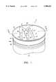
- FIG. 1is a perspective view of a bileaflet heart valve embodying various features of the present invention with the leaflets shown in the open position.
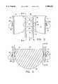
- FIG. 2is a sectional view taken generally along the line 2--2 of FIG. 1 showing the heart valve with the leaflets in the full open position, upon which a suture ring is installed that is designed to permit the valve to be mounted in the aortic position.
- FIG. 2Ais a sectional view taken generally along the line 2--2 of FIG. 1 showing the leaflets in the full open position, and with an alternative suture ring attached to the valve body.
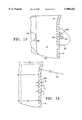
- FIG. 3is a view similar to FIG. 2 showing the leaflets in their prerotation orientation as they would be when the downstream flow of blood slows prior to reversal.
- FIG. 3Ais a fragmentary sectional view taken along the lines 3A--3A of FIG. 3.
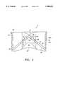
- FIG. 4is a view similar to FIG. 2, showing the leaflets in elevation and in their closed position, with the suture ring omitted.
- FIG. 5is a plan view looking downward at the valve shown in FIGS. 1 and 2 with the leaflets in the full open position.
- FIG. 6is a vertical sectional view through the valve taken generally along the line 6--6 of FIG. 2 with the leaflet in the full open position.
- FIG. 7is a perspective view of a leaflet from the valve of FIG. 1.
- FIG. 8is a side elevation view, reduced in size, of the leaflet of FIG. 7.
- FIG. 9is a front view of the leaflet of FIG. 8.
- FIG. 10is a fragmentary sectional view, enlarged in size, taken along the line 10--10 of FIGS. 5 and 6 with the sewing ring removed, which illustrates the freedom of the leaflet in question to rotate clockwise in the open position to assume an orientation of least resistance to downstream blood flow through the valve.
- FIG. 10Ais a full sectional view similar to FIG. 10 with the right-hand leaflet omitted and with the left-hand leaflet shown in the prerotation position.
- FIGS. 11 and 12are fragmentary horizontal sectional views taken respectively along the lines 11--11 and 12--12 of FIG. 3, with the leaflets removed.
- FIG. 13is a fragmentary sectional view taken generally along the line 13--13 of FIG. 2A.
- FIG. 14is a fragmentary sectional view, enlarged in size, illustrating the valve body wall structure.
- FIG. 15is a view similar to FIG. 14 showing the aortic sewing ring attached.
- FIG. 1Illustrated in FIG. 1 is a preferred embodiment of a prosthetic heart valve 11 constructed so as to embody various features of the present invention.
- heart valves having this constructionhave improved flow characteristics, particularly when the valve is in its fully open position, because the occluders can align parallel to the valve centerline or can align at slight deviations thereto depending upon instantaneous local variations in the blood flow path through the valve.
- occluder or leaflet orientationsminimize turbulence at the upstream edge surfaces thereof and substantially reduce drag and boundary layer separation along their major surfaces.
- This valve designalso provides good washing characteristics which prevents stagnation and potential clotting.
- heart valves of this designcan incorporate pivot arrangements which exhibit a rapid response to change in the direction of blood flow, i.e. in initiating both opening and closing, and which reduce hemolysis or similar injury to blood cells because of the manner in which the occluders close against the valve body.
- Heart valve 11includes a generally annular valve body 13 that supports a pair of pivoting occluders or leaflets 15 which open to allow the flow of blood in the downstream direction, as indicated by the arrow A in FIG. 2, and to alternately close to prevent any substantial backflow of blood through the valve in the upstream direction.
- the valve body 13defines a blood flow passageway in the form of its tabulated cylindrical interior wall surface 17 which lies downstream of a curved entrance region 19 at its upstream end, which is one of the important keys to the overall valve design that has now been found to result in substantially increased flow through the valve with low turbulence and substantially no generation of thrombosis.
- the curved entrance region 19which extends axially for a distance not greater than about one-third of the average axial length of the valve body are discussed hereinafter along with the operation of the valve.
- the interior surface downstream of the curved entrance region 19is generally rectilinear.
- the valve body 13preferably has a scalloped downstream profile so that there are, in effect, a pair of opposite shallow notches 27 formed in the contour of the valve body 13 in the regions just downstream of the thickened wall sections 21. In a bileaflet valve of this type, these notches 27 provide side openings into the central passageway which are aligned with the central blood flow passageway in the region between the outflow surfaces of the leaflets.
- the exterior surface of the relatively thin valve body 13 in the region downstream of the flared entrance section 19is substantially that of a surface of a right circular cylinder except for a slightly thickened central portion wherein a shallow groove 29 is formed between a pair of raised bands 29a.
- a metal stiffening attachment ring 30 of unique design(FIG. 2) which is formed with a plurality of circumferentially spaced apart inwardly protruding fingers 30a is mated therewith to add stability and rigidity to the valve body.
- the valve body itselfis preferably made of a suitable material, such as pyrocarbon or pyrocarbon-coated graphite, as is well known in this art, which has sufficient resiliency that it can be deformed so as to permit the insertion of the pair of leaflets 15 in their operative locations.
- the metal ring 30is also used to support the sewing ring of appropriate design, as broadly known in this art. Detailed examples of sewing or suture rings which can be employed are described in U.S. Pat. Nos. 4,535,483 and 5,178,633, the disclosures of which are incorporated herein by reference.
- the thickened exterior bands 29aare strategically located in the downstream cylindrical section of the valve body spaced from the flared entrance section 19.
- the shallow groove 29is located to accommodate the inwardly protruding fingers 30a of the metal ring 30 in either orientation as explained hereinafter.
- the groove 29, which is of arcuate cross section and constitutes the narrowest diameter on the exterior surfaceis located so that it is completely downstream of the fulcrums which are formed in recesses 25. This arrangement permits the suture rings to be accommodated in a location where the remaining tissue annulus will be in contact with a portion of the right circular cylindrical exterior surface of the valve body.
- the leaflets 15are preferably identical in form and shape and have two rectilinear, preferably flat, surfaces, i.e. an inflow surface 31 and an outflow surface 33.
- the inflow surfaceis arbitrarily defined as the surface which faces upstream when the leaflets are in the closed position, whereas the outflow surface is the opposite downstream facing surface.
- Each leafletis preferably of substantially constant thickness such that the surfaces 31 and 33 are parallel to each other.
- Other leaflet configurations, such as sections of hollow cylinders of circular or elliptical cross-sectionmay alternatively be employed, as discussed in more detail in U.S. Pat. No. 5,246,453, the disclosure of which is incorporated herein by reference.
- Each leaflet 15has a major arcuate downstream edge surface 35 which is shaped so as to abut and seat against the cylindrical side wall interior surface 17 of the valve body in the closed position.
- Eachalso has a mating minor edge surface 37 which is located at the upstream edge in the open position and which is preferably flat and formed at an angle so as to abut flush against the corresponding mating edge surface of the opposing leaflet in the closed position, as best seen in FIG. 4.
- the centerline planeis defined as a plane which includes the axial centerline of the passageway which is perpendicular to the flat wall surfaces 23.
- the pivot mechanismas explained hereinafter, is constructed such that the leaflets 15 can assume an orientation precisely parallel to the centerline plane when blood is flowing downstream through the valve body passageway.
- the ears 41have the same thickness as the flat leaflets and are elongated in an upstream-downstream direction viewed in their open orientation.
- the earshave upstream lateral edge surfaces 43 and downstream lateral edge surfaces 45 and are received in the cavities 25 in the flat wall regions of the thickened interior wall sections.
- the flat lateral edge surfaces 39 of the leafletsbear against the flat wall surfaces 23 surrounding the cavities and act as bearing surfaces during the movement of the leaflets between the open and closed position, and short transition surfaces 47 interconnect the surfaces 35 and 39.
- the valve body 13is formed with the thickened wall sections 21 in the regions where the cavities 25 are located, and preferably these thickened sections are formed with flaring transition surfaces, i.e. an upstream transition surface 49 and a downstream transition surface 51 which lead smoothly from the circular entrance region and the circular exit region of the valve body to the flat wall surfaces 23 wherein the cavities 25 are located.
- a surface such as the surface 49may be referred to as a radial swept surface.
- the flow passageway through the valve bodyis generally circular in cross-section except for the two thickened sections 21 which extend inward to the flat wall surfaces 23.
- the plane containing the centerline axis of the generally circular passageway that is oriented perpendicular to the flat surfaces 23is referred to as the centerline plane and is frequently used for reference purposes throughout this specification.
- the cavities 25 formed in the valve bodyare in the form of pairs of side-by-side cavities which are mirror images of each other and which are respectively located on opposite sides of the centerline plane.
- the cavitieseach have a generally flat rear wall 54 which is surrounded by an irregular side wall contour 53 that assists in guiding the leaflets along the desired path in moving between the open and closed positions.
- the cavitiesare formed to have an upstream lobe 57 and a downstream lobe 59 on opposite sides of an intermediate throat section 61.
- the intermediate throat sectionis formed by a pair of curved fulcrums, termed an outward fulcrum 63 and an inward fulcrum 65 with respect to their location as reference to the centerline plane of the valve body.
- the upstream lobe 57is formed with an inclined flat camming wall 67 which extends upstream from a location above the outward fulcrum 63 and joins a concavely curved wall section 69 which leads gradually downstream from the junction point.
- the downstream lobe 59includes a flat wall section 71 immediately downstream of the inward fulcrum 65, which serves as a stop against which the leaflet ears 41 can assume a precisely parallel orientation in the full open position, and a downstream sloping section 73 which extends from the downstream end of the flat wall section to the arcuate bottom wall 75 of the downstream lobe.
- the leaflets 15are installed in the valve body 13 by squeezing the body at diametrically opposite locations so as to cause the flat wall sections 23 to spread sufficiently far apart to permit the leaflets to be fitted into the valve body so that the ears are received in the cavities.
- the method and apparatus disclosed in U.S. Pat. No. 5,336,259, issued Aug. 9, 1994,can advantageously be used for the insertion of the leaflets.
- the valve body 13returns to its original annular configuration leaving only the desired minimal clearance between the flat wall surfaces 23 of the valve body and the straight lateral edge surfaces 39 of the leaflets.
- the metal stabilizing ring 30can be appropriately installed in the exterior circumferential groove 29 either following the installation of the leaflets or before installing the leaflets.
- the thickened bands 29aso that an inclined ramp is formed at the downstream edge of the downstream one of the two bands, it is possible to install the metal ring 30 by sliding it upward from the downstream end of the valve body 13 and allowing the fingers 30a to snap into place; however, it should be understood that the ring could be installed by shrink-fitting if desired.
- the unique stiffening ring 30is designed to facilitate the installation of either an aortic sewing ring or a mitral sewing ring exterior of the valve body 13, as best seen by comparing FIGS. 2 and 2A.
- an aortic sewing ring 81is illustrated which is designed to leave the upstream exterior surface of the valve body free and clear to permit its insertion into the aortic annulus from which the defective natural valve was excised.
- the stiffening ring 30is slid onto the valve body 13 from the downstream end with the radially inward protruding fingers leading. As best seen in FIGS.
- these fingers 30aare connected by relatively thin necks to the main portion of the stiffening ring, and the fingers have curved radially interior faces which are proportioned to the curvature of the grooves 29.
- the leading projection sectionreaches the downstream band 29a flanking the groove 29, deflection of the fingers outward permits upstream travel to continue until the groove is reached, into which the projecting fingers then snap into place, as best seen in FIG. 15, with the main portion of the stiffening ring tightly surrounding the downstream cylindrical band 29a of the valve body and preferably placing it in at least slight compression.
- the depth of the shallow groove 29is such that the thickness T 2 (FIG. 14) at the location of the groove is equal to at least about 85% of the thickness T 1 of the major cylindrical section of the valve body.
- the thickness T 3 at the location of the bands 29aneed not be greater than about 120% of the thickness T 1 .
- each heart valve excised from the heart of a particular patientwill vary with each patient, and therefore a surgeon should have available a set of prosthetic valves of different sizes generally ranging in exterior diameter from about 19 millimeters to 33 millimeters in diameter for fully grown adults.
- the reference measurementis that of the tissue annulus remaining after the defective natural valve has been excised.
- the present valve designis such that it can be effectively installed so that the tissue annulus is in direct contact with the outer surface of the valve body 13 for valves that are installed both in the aortic position and in the mitral position.
- tissue annulus of the patientwill be in contact with the exterior surface of the valve body in the regions marked "A" in FIGS. 2 and 2A.
- FIG. 2AOne result of this arrangement is evident from FIG. 2A where it can be seen that the diameter of the substantially circular passageway through the valve is a very large percentage of the diameter of the tissue annulus, which is made possible because of the relative thinness of the major portion of the valve body wall, particularly in the region of the tissue annulus.
- the ringcan be heated and shrink-fit onto the valve body so that the main body of the ring 30 is in contact with the desired band 29a.
- shrink-fittingallows greater compressive force to be applied to a pyrocarbon structure by such a metal ring and can improve the structural properties of the pyrocarbon which, as indicated above, is the preferred material of construction.
- a metalis chosen which has sufficient resiliency to return to its perfectly annular shape following removal of the squeezing force.
- the two leaflets 15With the heart valve 11 operatively installed in a patient in either the mitral or the aortic position, when a pumping stroke of the heart causes downstream flow of blood through the valve, the two leaflets 15 will assume an open equilibrium position with respect to instantaneous path of the blood during conditions of high flow through the passageway. This may be an orientation where the leaflets 15 are aligned precisely parallel to the centerline plane, as illustrated in FIG. 2. However, should the dynamic forces within the valve body passageway vary, the leaflets may pivot to some extent to accommodate such variance; for example, the left-hand leaflet can rotate slightly clockwise to maintain a low energy position with respect to such an instantaneous change in the direction of the blood flow.
- valve body 13contributes to the achievement of smooth nonturbulent flow and the absence of stasis.
- the toroidal curvature of the curved entrance end 19 leading to a generally cylindrical valve body of substantial overall axial lengthhas been found to achieve this desired end. More specifically, the construction of a valve body to have a curved entrance transition to a tabulated cylindrical, elongated passageway has been found to provide very low pressure drop for a passageway of a particular diameter.
- the average axial length of the valveis preferably at least 50% of the interior diameter thereof.
- the entrance sectionshould constitute not more than about one-third of the average axial length of the valve body, and it should smoothly join with the downstream section, preferably being tangent thereto.
- the entrance sectionis preferably essentially a section of the surface of a torus.
- the torusis selected so that the interior diameter of the torus is between 80% and 120% of the diameter of the interior circular cross-section of the passageway through the valve body, and preferably between about 90% and 100%. Most preferably it is about 100% so that it will be substantially tangent to the right circular cylindrical downstream interior surface; if not, a short transition section is included.
- the radius of curvature of the circle that is revolved to create the torusis between about 28% and about 80% of the radius of the valve body and preferably between about 40% and about 65%.
- the interior radius of the valve bodyis marked “R 1 "
- the radius of curvature of the torusis marked “R 2 ".
- the exterior diameter D E at the entrance end 19should not be more than about 10% greater than the exterior diameter D v of the major cylindrical outer surface of the valve body; preferably, it is about 6-7% greater.
- the leafletscan assume such precisely parallel alignment as described hereinbefore, when the peak downstream flow of blood has passed and it is slowing to approach zero flow, the drag of the bloodstream against the leaflets 15 can cause the ears 41 to move slightly downstream in the downstream lobes 59 which results in a pivoting of the leaflets a few degrees toward the closed orientation as shown in FIGS. 3 and 10A. Then, as the reverse flow of blood upstream through the valve begins, the leaflets immediately translate upstream, causing the ears to engage the camming surfaces 67 of the contoured wall of the upstream lobe 57 above the outward fulcrums 63 which causes the leaflets to very promptly pivot toward their closed positions.
- This upstream translational movement of the ear 41 in the cavity 25assures that the pivoting of each leaflet toward its closed position orientation occurs very promptly upon the beginning of reverse flow and continues until the upstream edges of the leaflet ears reach the top of the upstream lobes 57.
- the leaflets 15are oriented sufficiently transverse to the backflow of blood that the force of the blood against the outflow surfaces 33 becomes predominant, forcing the leaflets against the outward fulcrums 63 and continuing the pivoting motion.
- the final movement of the leaflets to the closed positionis guided by the movement of the upstream lateral edge surfaces 43 of the ears along the downstream curved portion 69 of the upstream lobes 57 while the ears remain essentially in contact with the outward fulcrums 63.
- the mating edges 37 of the leafletsabut each other, and the downstream arcuate edge surfaces 35 abut the cylindrical interior surface 17 of the valve body.
- the force of the blood against the outflow surfaces 33 of the leafletsis borne by the seating of the arcuate edge surfaces 35 against the interior valve body wall 17 and by the ears 41 bearing against the outward fulcrums 63 which also directs forces so that the two mating edges 37 are pressed together in sealing arrangement.
- the proportioning of the leaflets 15 within the valve body 13is such that some controlled leakage occurs in the cavities in an upstream direction past the ears.
- downstream displacement, i.e. translation, of the leaflets 15initially occurs as a result of the force of the blood against the inflow surfaces 31.
- the ears 41are quickly displaced so that they contact the inward fulcrums 65 and create an eccentric pivot axis about which opening pivoting motion quickly begins. Because of the shape of the downstream lobes, when blood flow reaches its maximum, the dynamic forces of the bloodstream in the passageway can cause the leaflets to assume a precisely parallel position where the ears 41 are juxtaposed flush against the flat walls 71 just downstream from the inward fulcrums 65.
- the overall design of the valveis such that gross hemodynamics in terms of energy loss per cardiac cycle are superior to mechanical heart valves that are presently commercially available. Because blood is a very delicate tissue and even minor abuses caused by turbulence and high shear can result in thrombosis and emboli generation at local regions of stagnation, this valve design which avoids the creation of excessive turbulence and accompanying high shear stresses is particularly advantageous. Moreover, the design is such that the foregoing is accomplished while also maintaining prompt closing which achieves reduced regurgitation without increased turbulence.
Landscapes
- Health & Medical Sciences (AREA)
- Cardiology (AREA)
- Oral & Maxillofacial Surgery (AREA)
- Transplantation (AREA)
- Engineering & Computer Science (AREA)
- Biomedical Technology (AREA)
- Heart & Thoracic Surgery (AREA)
- Vascular Medicine (AREA)
- Life Sciences & Earth Sciences (AREA)
- Animal Behavior & Ethology (AREA)
- General Health & Medical Sciences (AREA)
- Public Health (AREA)
- Veterinary Medicine (AREA)
- Prostheses (AREA)
Abstract
Description
Claims (13)
Priority Applications (1)
| Application Number | Priority Date | Filing Date | Title |
|---|---|---|---|
| US09/027,358US5908452A (en) | 1995-05-16 | 1998-02-20 | Prosthetic heart valve with improved blood flow |
Applications Claiming Priority (2)
| Application Number | Priority Date | Filing Date | Title |
|---|---|---|---|
| US08/441,809US5772694A (en) | 1995-05-16 | 1995-05-16 | Prosthetic heart valve with improved blood flow |
| US09/027,358US5908452A (en) | 1995-05-16 | 1998-02-20 | Prosthetic heart valve with improved blood flow |
Related Parent Applications (1)
| Application Number | Title | Priority Date | Filing Date |
|---|---|---|---|
| US08/441,809ContinuationUS5772694A (en) | 1995-05-16 | 1995-05-16 | Prosthetic heart valve with improved blood flow |
Publications (1)
| Publication Number | Publication Date |
|---|---|
| US5908452Atrue US5908452A (en) | 1999-06-01 |
Family
ID=23754377
Family Applications (2)
| Application Number | Title | Priority Date | Filing Date |
|---|---|---|---|
| US08/441,809Expired - LifetimeUS5772694A (en) | 1995-05-16 | 1995-05-16 | Prosthetic heart valve with improved blood flow |
| US09/027,358Expired - LifetimeUS5908452A (en) | 1995-05-16 | 1998-02-20 | Prosthetic heart valve with improved blood flow |
Family Applications Before (1)
| Application Number | Title | Priority Date | Filing Date |
|---|---|---|---|
| US08/441,809Expired - LifetimeUS5772694A (en) | 1995-05-16 | 1995-05-16 | Prosthetic heart valve with improved blood flow |
Country Status (1)
| Country | Link |
|---|---|
| US (2) | US5772694A (en) |
Cited By (45)
| Publication number | Priority date | Publication date | Assignee | Title |
|---|---|---|---|---|
| US6086612A (en)* | 1996-06-24 | 2000-07-11 | Adiam Medizintechnik Gmbh & Co. Kg | Mitral valve prosthesis |
| US6610071B1 (en) | 1999-07-26 | 2003-08-26 | Beth Israel Deaconess Medical Center | Suture system |
| US6730122B1 (en) | 2000-11-28 | 2004-05-04 | St. Jude Medical, Inc. | Prosthetic heart valve with increased lumen |
| US20040225352A1 (en)* | 2003-03-12 | 2004-11-11 | Osborne Thomas A. | Prosthetic valve that permits retrograde flow |
| US20050210311A1 (en)* | 2004-03-08 | 2005-09-22 | Rodeheffer Thomas L | Method and system for probabilistic defect isolation |
| US20060058889A1 (en)* | 2004-09-10 | 2006-03-16 | Case Brian C | Prosthetic valve with pores |
| US20060106454A1 (en)* | 2004-10-29 | 2006-05-18 | Osborne Thomas A | Intraluminal medical device with cannula for controlled retrograde flow |
| US20060149360A1 (en)* | 2003-07-08 | 2006-07-06 | Ventor Technologies Ltd. | Fluid flow prosthetic device |
| WO2006081213A1 (en) | 2005-01-27 | 2006-08-03 | Valve Special Purpose Co., Llc | Heart valve inserter |
| US20060259134A1 (en)* | 2003-07-08 | 2006-11-16 | Ehud Schwammenthal | Implantable prosthetic devices particularly for transarterial delivery in the treatment of aortic stenosis, and methods of implanting such devices |
| US20080071369A1 (en)* | 2006-09-19 | 2008-03-20 | Yosi Tuval | Valve fixation member having engagement arms |
| US20090240320A1 (en)* | 2008-03-18 | 2009-09-24 | Yosi Tuval | Valve suturing and implantation procedures |
| US7951197B2 (en) | 2005-04-08 | 2011-05-31 | Medtronic, Inc. | Two-piece prosthetic valves with snap-in connection and methods for use |
| US7959674B2 (en)* | 2002-07-16 | 2011-06-14 | Medtronic, Inc. | Suture locking assembly and method of use |
| US7967857B2 (en) | 2006-01-27 | 2011-06-28 | Medtronic, Inc. | Gasket with spring collar for prosthetic heart valves and methods for making and using them |
| US7972377B2 (en) | 2001-12-27 | 2011-07-05 | Medtronic, Inc. | Bioprosthetic heart valve |
| US7981153B2 (en) | 2002-12-20 | 2011-07-19 | Medtronic, Inc. | Biologically implantable prosthesis methods of using |
| US8021421B2 (en) | 2003-08-22 | 2011-09-20 | Medtronic, Inc. | Prosthesis heart valve fixturing device |
| US8211169B2 (en) | 2005-05-27 | 2012-07-03 | Medtronic, Inc. | Gasket with collar for prosthetic heart valves and methods for using them |
| US8603161B2 (en) | 2003-10-08 | 2013-12-10 | Medtronic, Inc. | Attachment device and methods of using the same |
| US8652204B2 (en) | 2010-04-01 | 2014-02-18 | Medtronic, Inc. | Transcatheter valve with torsion spring fixation and related systems and methods |
| US8821569B2 (en) | 2006-04-29 | 2014-09-02 | Medtronic, Inc. | Multiple component prosthetic heart valve assemblies and methods for delivering them |
| US8834564B2 (en) | 2006-09-19 | 2014-09-16 | Medtronic, Inc. | Sinus-engaging valve fixation member |
| US8979922B2 (en) | 2004-03-11 | 2015-03-17 | Percutaneous Cardiovascular Solutions Pty Limited | Percutaneous heart valve prosthesis |
| USD732666S1 (en) | 2005-05-13 | 2015-06-23 | Medtronic Corevalve, Inc. | Heart valve prosthesis |
| US10166014B2 (en) | 2008-11-21 | 2019-01-01 | Percutaneous Cardiovascular Solutions Pty Ltd | Heart valve prosthesis and method |
| US10182907B2 (en) | 2007-05-02 | 2019-01-22 | Novostia Sa | Mechanical prosthetic heart valve |
| US10413400B2 (en) | 2015-02-24 | 2019-09-17 | Rijksuniversiteit Groningen | Mechanical heart valve prosthesis for the right ventricle |
| US10940167B2 (en) | 2012-02-10 | 2021-03-09 | Cvdevices, Llc | Methods and uses of biological tissues for various stent and other medical applications |
| US10993805B2 (en) | 2008-02-26 | 2021-05-04 | Jenavalve Technology, Inc. | Stent for the positioning and anchoring of a valvular prosthesis in an implantation site in the heart of a patient |
| US11065138B2 (en) | 2016-05-13 | 2021-07-20 | Jenavalve Technology, Inc. | Heart valve prosthesis delivery system and method for delivery of heart valve prosthesis with introducer sheath and loading system |
| US11185405B2 (en) | 2013-08-30 | 2021-11-30 | Jenavalve Technology, Inc. | Radially collapsible frame for a prosthetic valve and method for manufacturing such a frame |
| US11197754B2 (en) | 2017-01-27 | 2021-12-14 | Jenavalve Technology, Inc. | Heart valve mimicry |
| US11259919B2 (en) | 2008-01-24 | 2022-03-01 | Medtronic, Inc. | Stents for prosthetic heart valves |
| US11284999B2 (en) | 2008-01-24 | 2022-03-29 | Medtronic, Inc. | Stents for prosthetic heart valves |
| US11304801B2 (en) | 2006-09-19 | 2022-04-19 | Medtronic Ventor Technologies Ltd. | Sinus-engaging valve fixation member |
| US11337800B2 (en) | 2015-05-01 | 2022-05-24 | Jenavalve Technology, Inc. | Device and method with reduced pacemaker rate in heart valve replacement |
| US11357624B2 (en) | 2007-04-13 | 2022-06-14 | Jenavalve Technology, Inc. | Medical device for treating a heart valve insufficiency |
| US11406495B2 (en) | 2013-02-11 | 2022-08-09 | Cook Medical Technologies Llc | Expandable support frame and medical device |
| US11517431B2 (en) | 2005-01-20 | 2022-12-06 | Jenavalve Technology, Inc. | Catheter system for implantation of prosthetic heart valves |
| US11564794B2 (en) | 2008-02-26 | 2023-01-31 | Jenavalve Technology, Inc. | Stent for the positioning and anchoring of a valvular prosthesis in an implantation site in the heart of a patient |
| US11589981B2 (en) | 2010-05-25 | 2023-02-28 | Jenavalve Technology, Inc. | Prosthetic heart valve and transcatheter delivered endoprosthesis comprising a prosthetic heart valve and a stent |
| US12121461B2 (en) | 2015-03-20 | 2024-10-22 | Jenavalve Technology, Inc. | Heart valve prosthesis delivery system and method for delivery of heart valve prosthesis with introducer sheath |
| US12171658B2 (en) | 2022-11-09 | 2024-12-24 | Jenavalve Technology, Inc. | Catheter system for sequential deployment of an expandable implant |
| US12414854B2 (en) | 2010-05-20 | 2025-09-16 | Jenavalve Technology, Inc. | Catheter system for introducing an expandable stent into the body of a patient |
Families Citing this family (29)
| Publication number | Priority date | Publication date | Assignee | Title |
|---|---|---|---|---|
| US6395024B1 (en) | 1997-05-20 | 2002-05-28 | Triflo Medical, Inc. | Mechanical heart valve |
| US5919226A (en) | 1997-07-22 | 1999-07-06 | Medtronic, Inc. | Mechanical heart valve prosthesis |
| US6951573B1 (en) | 2001-12-22 | 2005-10-04 | Dilling Emery W | Prosthetic aortic valve |
| EP2075014B9 (en) | 2002-05-24 | 2012-02-01 | Angiotech International Ag | Compositions and methods for coating medical implants |
| US20080086202A1 (en)* | 2002-09-27 | 2008-04-10 | Didier Lapeyre | Mechanical heart valve |
| US20050229982A1 (en)* | 2004-04-20 | 2005-10-20 | Gonzales Peter D | Pipe inlet/outlet flow enhancement device |
| US7575594B2 (en)* | 2004-12-30 | 2009-08-18 | Sieracki Jeffrey M | Shock dampening biocompatible valve |
| AU2006259415B2 (en)* | 2005-06-15 | 2012-08-30 | Massachusetts Institute Of Technology | Amine-containing lipids and uses thereof |
| CN104910025B (en) | 2008-11-07 | 2019-07-16 | 麻省理工学院 | Alkamine lipid and its purposes |
| HUE038039T2 (en) | 2009-12-01 | 2018-09-28 | Translate Bio Inc | Delivery of mrna for the augmentation of proteins and enzymes in human genetic diseases |
| EP2609135A4 (en) | 2010-08-26 | 2015-05-20 | Massachusetts Inst Technology | POLY (BETA-AMINO ALCOHOLS), THEIR PREPARATION AND USES THEREOF |
| EP2691443B1 (en) | 2011-03-28 | 2021-02-17 | Massachusetts Institute of Technology | Conjugated lipomers and uses thereof |
| PL2717893T3 (en) | 2011-06-08 | 2019-12-31 | Translate Bio, Inc. | Lipid nanoparticle compositions and methods for mRNA delivery |
| US9585746B2 (en)* | 2011-07-29 | 2017-03-07 | Carnegie Mellon University | Artificial valved conduits for cardiac reconstructive procedures and methods for their production |
| WO2013185067A1 (en) | 2012-06-08 | 2013-12-12 | Shire Human Genetic Therapies, Inc. | Nuclease resistant polynucleotides and uses thereof |
| IL290953B2 (en) | 2013-03-14 | 2024-01-01 | Ethris Gmbh | Cftr mrna compositions and related methods and uses |
| AU2014236396A1 (en) | 2013-03-14 | 2015-08-13 | Shire Human Genetic Therapies, Inc. | Methods for purification of messenger RNA |
| US9315472B2 (en) | 2013-05-01 | 2016-04-19 | Massachusetts Institute Of Technology | 1,3,5-triazinane-2,4,6-trione derivatives and uses thereof |
| KR102096796B1 (en) | 2013-10-22 | 2020-05-27 | 샤이어 휴먼 지네틱 테라피즈 인크. | Lipid formulations for delivery of messenger rna |
| EA201992208A1 (en) | 2013-10-22 | 2020-07-31 | Транслейт Био, Инк. | TREATMENT OF PHENYLKETONURIA USING mRNA |
| CN106413811A (en) | 2013-10-22 | 2017-02-15 | 夏尔人类遗传性治疗公司 | Mrna therapy for argininosuccinate synthetase deficiency |
| SG11201608725YA (en) | 2014-04-25 | 2016-11-29 | Shire Human Genetic Therapies | Methods for purification of messenger rna |
| CA3211902A1 (en) | 2014-05-30 | 2015-12-03 | Translate Bio, Inc. | Biodegradable lipids for delivery of nucleic acids |
| PE20171238A1 (en) | 2014-06-24 | 2017-08-24 | Shire Human Genetic Therapies | STEREOCHEMICALLY ENRICHED COMPOSITIONS FOR NUCLEIC ACIDS ADMINISTRATION |
| US9840479B2 (en) | 2014-07-02 | 2017-12-12 | Massachusetts Institute Of Technology | Polyamine-fatty acid derived lipidoids and uses thereof |
| WO2018157154A2 (en) | 2017-02-27 | 2018-08-30 | Translate Bio, Inc. | Novel codon-optimized cftr mrna |
| US11173190B2 (en) | 2017-05-16 | 2021-11-16 | Translate Bio, Inc. | Treatment of cystic fibrosis by delivery of codon-optimized mRNA encoding CFTR |
| EP3841208A1 (en) | 2018-08-24 | 2021-06-30 | Translate Bio, Inc. | Methods for purification of messenger rna |
| WO2020106946A1 (en) | 2018-11-21 | 2020-05-28 | Translate Bio, Inc. | TREATMENT OF CYSTIC FIBROSIS BY DELIVERY OF NEBULIZED mRNA ENCODING CFTR |
Citations (12)
| Publication number | Priority date | Publication date | Assignee | Title |
|---|---|---|---|---|
| US3727240A (en)* | 1969-04-21 | 1973-04-17 | Medical Inc | Suturing member for implantable devices such as heart valves |
| US4328592A (en)* | 1979-08-07 | 1982-05-11 | Hemex, Inc. | Heart valve prosthesis |
| US4363142A (en)* | 1979-10-12 | 1982-12-14 | Mitral Medical, Inc. | Prosthetic heart valve |
| US4535483A (en)* | 1983-01-17 | 1985-08-20 | Hemex, Inc. | Suture rings for heart valves |
| US4679546A (en)* | 1984-10-17 | 1987-07-14 | Applied Medical Technics B.V. | Implantable shut-off device |
| US4775378A (en)* | 1987-01-22 | 1988-10-04 | B. Braun Melsungen Ag | Cardiac valve prosthesis |
| US4799930A (en)* | 1987-01-22 | 1989-01-24 | B. Braun Melsungen Ag | Cardiac valve prosthesis |
| US4846830A (en)* | 1987-01-22 | 1989-07-11 | B. Braun Melsungen Ag | Cardiac valve prosthesis |
| US4995881A (en)* | 1988-08-25 | 1991-02-26 | B. Braun Melsungen Ag | Heart valve prosthesis |
| US5078739A (en)* | 1990-07-20 | 1992-01-07 | Janus Biomedical, Inc. | Bileaflet heart valve with external leaflets |
| US5171263A (en)* | 1989-12-20 | 1992-12-15 | Commissariat A L'energie Atomique | Cardiac valve with flaps pivoting on balls |
| US5178632A (en)* | 1992-06-09 | 1993-01-12 | Hanson Richard D | Bi-leaflet heart valve prosthesis |
Family Cites Families (5)
| Publication number | Priority date | Publication date | Assignee | Title |
|---|---|---|---|---|
| US4276658A (en)* | 1977-11-02 | 1981-07-07 | St. Jude Medical, Inc. | Heart valve prosthesis |
| SU1572602A1 (en)* | 1987-06-23 | 1990-06-23 | Предприятие П/Я А-1619 | Heart valve prosthesis |
| IT1218947B (en)* | 1988-01-12 | 1990-04-24 | Sorin Biomedica Spa | CARDIAC VALVE PROSTHESIS |
| US4892540A (en)* | 1988-04-21 | 1990-01-09 | Sorin Biomedica S.P.A. | Two-leaflet prosthetic heart valve |
| US5192309A (en)* | 1991-03-25 | 1993-03-09 | Onx, Inc. | Prosthetic heart valve |
- 1995
- 1995-05-16USUS08/441,809patent/US5772694A/ennot_activeExpired - Lifetime
- 1998
- 1998-02-20USUS09/027,358patent/US5908452A/ennot_activeExpired - Lifetime
Patent Citations (12)
| Publication number | Priority date | Publication date | Assignee | Title |
|---|---|---|---|---|
| US3727240A (en)* | 1969-04-21 | 1973-04-17 | Medical Inc | Suturing member for implantable devices such as heart valves |
| US4328592A (en)* | 1979-08-07 | 1982-05-11 | Hemex, Inc. | Heart valve prosthesis |
| US4363142A (en)* | 1979-10-12 | 1982-12-14 | Mitral Medical, Inc. | Prosthetic heart valve |
| US4535483A (en)* | 1983-01-17 | 1985-08-20 | Hemex, Inc. | Suture rings for heart valves |
| US4679546A (en)* | 1984-10-17 | 1987-07-14 | Applied Medical Technics B.V. | Implantable shut-off device |
| US4775378A (en)* | 1987-01-22 | 1988-10-04 | B. Braun Melsungen Ag | Cardiac valve prosthesis |
| US4799930A (en)* | 1987-01-22 | 1989-01-24 | B. Braun Melsungen Ag | Cardiac valve prosthesis |
| US4846830A (en)* | 1987-01-22 | 1989-07-11 | B. Braun Melsungen Ag | Cardiac valve prosthesis |
| US4995881A (en)* | 1988-08-25 | 1991-02-26 | B. Braun Melsungen Ag | Heart valve prosthesis |
| US5171263A (en)* | 1989-12-20 | 1992-12-15 | Commissariat A L'energie Atomique | Cardiac valve with flaps pivoting on balls |
| US5078739A (en)* | 1990-07-20 | 1992-01-07 | Janus Biomedical, Inc. | Bileaflet heart valve with external leaflets |
| US5178632A (en)* | 1992-06-09 | 1993-01-12 | Hanson Richard D | Bi-leaflet heart valve prosthesis |
Non-Patent Citations (2)
| Title |
|---|
| M. Knoch, H. Reul and G. Rau, "Flow Characteristics of Six Mechanical Heart Valve Prostheses in Aortic Position: Design Related Model Studies", Surgery for Heart Valve Disease (ed. Endre Bodnar) , ICR Publishers, London (1990) ISBN 1-872743-00-5, pp. 590-601. |
| M. Knoch, H. Reul and G. Rau, Flow Characteristics of Six Mechanical Heart Valve Prostheses in Aortic Position: Design Related Model Studies , Surgery for Heart Valve Disease (ed. Endre Bodnar) , ICR Publishers, London (1990) ISBN 1 872743 00 5, pp. 590 601.* |
Cited By (111)
| Publication number | Priority date | Publication date | Assignee | Title |
|---|---|---|---|---|
| US6086612A (en)* | 1996-06-24 | 2000-07-11 | Adiam Medizintechnik Gmbh & Co. Kg | Mitral valve prosthesis |
| US6610071B1 (en) | 1999-07-26 | 2003-08-26 | Beth Israel Deaconess Medical Center | Suture system |
| US20040106949A1 (en)* | 1999-07-26 | 2004-06-03 | Beth Israel Deaconess Medical Center | Suture system |
| US8097005B2 (en) | 1999-07-26 | 2012-01-17 | Beth Israel Deaconess Medical Center | Suture system |
| US6730122B1 (en) | 2000-11-28 | 2004-05-04 | St. Jude Medical, Inc. | Prosthetic heart valve with increased lumen |
| US7972377B2 (en) | 2001-12-27 | 2011-07-05 | Medtronic, Inc. | Bioprosthetic heart valve |
| US7959674B2 (en)* | 2002-07-16 | 2011-06-14 | Medtronic, Inc. | Suture locking assembly and method of use |
| US8349003B2 (en) | 2002-07-16 | 2013-01-08 | Medtronic, Inc. | Suture locking assembly and method of use |
| US9333078B2 (en) | 2002-12-20 | 2016-05-10 | Medtronic, Inc. | Heart valve assemblies |
| US8623080B2 (en) | 2002-12-20 | 2014-01-07 | Medtronic, Inc. | Biologically implantable prosthesis and methods of using the same |
| US8460373B2 (en) | 2002-12-20 | 2013-06-11 | Medtronic, Inc. | Method for implanting a heart valve within an annulus of a patient |
| US8025695B2 (en) | 2002-12-20 | 2011-09-27 | Medtronic, Inc. | Biologically implantable heart valve system |
| US8551162B2 (en) | 2002-12-20 | 2013-10-08 | Medtronic, Inc. | Biologically implantable prosthesis |
| US10595991B2 (en) | 2002-12-20 | 2020-03-24 | Medtronic, Inc. | Heart valve assemblies |
| US7981153B2 (en) | 2002-12-20 | 2011-07-19 | Medtronic, Inc. | Biologically implantable prosthesis methods of using |
| US20040225352A1 (en)* | 2003-03-12 | 2004-11-11 | Osborne Thomas A. | Prosthetic valve that permits retrograde flow |
| US8021417B2 (en) | 2003-03-12 | 2011-09-20 | Cook Medical Technologies Llc | Prosthetic valve that permits retrograde flow |
| US20080249612A1 (en)* | 2003-03-12 | 2008-10-09 | Cook Incorporated | Prosthetic valve that permits retrograde flow |
| US7402171B2 (en) | 2003-03-12 | 2008-07-22 | Cook Incorporated | Prosthetic valve that permits retrograde flow |
| US7442204B2 (en) | 2003-07-08 | 2008-10-28 | Ventor Technologies, Ltd. | Fluid flow prosthetic device |
| US7429269B2 (en) | 2003-07-08 | 2008-09-30 | Ventor Technologies Ltd. | Aortic prosthetic devices |
| US20070185565A1 (en)* | 2003-07-08 | 2007-08-09 | Ventor Technologies Ltd. | Fluid flow prosthetic device |
| US7201772B2 (en) | 2003-07-08 | 2007-04-10 | Ventor Technologies, Ltd. | Fluid flow prosthetic device |
| US20060259134A1 (en)* | 2003-07-08 | 2006-11-16 | Ehud Schwammenthal | Implantable prosthetic devices particularly for transarterial delivery in the treatment of aortic stenosis, and methods of implanting such devices |
| US20060149360A1 (en)* | 2003-07-08 | 2006-07-06 | Ventor Technologies Ltd. | Fluid flow prosthetic device |
| US8021421B2 (en) | 2003-08-22 | 2011-09-20 | Medtronic, Inc. | Prosthesis heart valve fixturing device |
| US8747463B2 (en) | 2003-08-22 | 2014-06-10 | Medtronic, Inc. | Methods of using a prosthesis fixturing device |
| US8603161B2 (en) | 2003-10-08 | 2013-12-10 | Medtronic, Inc. | Attachment device and methods of using the same |
| US20050210311A1 (en)* | 2004-03-08 | 2005-09-22 | Rodeheffer Thomas L | Method and system for probabilistic defect isolation |
| US11974918B2 (en) | 2004-03-11 | 2024-05-07 | Percutaneous Cardiovascular Solutions Pty Ltd | Percutaneous heart valve prosthesis |
| US11744705B2 (en) | 2004-03-11 | 2023-09-05 | Percutaneous Cardiovascular Solutions Pty Ltd | Method of implanting a heart valve prosthesis |
| US8979922B2 (en) | 2004-03-11 | 2015-03-17 | Percutaneous Cardiovascular Solutions Pty Limited | Percutaneous heart valve prosthesis |
| US11213390B2 (en) | 2004-03-11 | 2022-01-04 | Percutaneous Cardiovascular Solutions Pty Ltd | Method of implanting a heart valve prosthesis |
| US10993806B2 (en) | 2004-03-11 | 2021-05-04 | Percutaneous Cardiovascular Solutions Pty Ltd | Percutaneous heart valve prosthesis |
| US10213298B2 (en) | 2004-03-11 | 2019-02-26 | Percutaneous Cardiovascular Solutions Pty Ltd | Percutaneous heart valve prosthesis |
| US10085835B2 (en) | 2004-03-11 | 2018-10-02 | Percutaneous Cardiovascular Solutions Pty Ltd | Percutaneous heart valve prosthesis |
| US11622856B2 (en) | 2004-03-11 | 2023-04-11 | Percutaneous Cardiovascular Solutions Pty Ltd | Percutaneous heart valve prosthesis |
| US20060058889A1 (en)* | 2004-09-10 | 2006-03-16 | Case Brian C | Prosthetic valve with pores |
| US7361189B2 (en) | 2004-09-10 | 2008-04-22 | Cook Incorporated | Prosthetic valve with pores |
| US20060106454A1 (en)* | 2004-10-29 | 2006-05-18 | Osborne Thomas A | Intraluminal medical device with cannula for controlled retrograde flow |
| US7563276B2 (en) | 2004-10-29 | 2009-07-21 | Cook Incorporated | Intraluminal medical device with cannula for controlled retrograde flow |
| US11517431B2 (en) | 2005-01-20 | 2022-12-06 | Jenavalve Technology, Inc. | Catheter system for implantation of prosthetic heart valves |
| US8303652B2 (en) | 2005-01-27 | 2012-11-06 | On-X Life Technologies, Inc. | Heart valve inserter |
| US20070219629A1 (en)* | 2005-01-27 | 2007-09-20 | Valve Special Purpose Co., Llc | Heart Valve Inserter |
| WO2006081213A1 (en) | 2005-01-27 | 2006-08-03 | Valve Special Purpose Co., Llc | Heart valve inserter |
| US8500802B2 (en) | 2005-04-08 | 2013-08-06 | Medtronic, Inc. | Two-piece prosthetic valves with snap-in connection and methods for use |
| US7951197B2 (en) | 2005-04-08 | 2011-05-31 | Medtronic, Inc. | Two-piece prosthetic valves with snap-in connection and methods for use |
| USD812226S1 (en) | 2005-05-13 | 2018-03-06 | Medtronic Corevalve Llc | Heart valve prosthesis |
| USD732666S1 (en) | 2005-05-13 | 2015-06-23 | Medtronic Corevalve, Inc. | Heart valve prosthesis |
| US8211169B2 (en) | 2005-05-27 | 2012-07-03 | Medtronic, Inc. | Gasket with collar for prosthetic heart valves and methods for using them |
| US7967857B2 (en) | 2006-01-27 | 2011-06-28 | Medtronic, Inc. | Gasket with spring collar for prosthetic heart valves and methods for making and using them |
| US8821569B2 (en) | 2006-04-29 | 2014-09-02 | Medtronic, Inc. | Multiple component prosthetic heart valve assemblies and methods for delivering them |
| US8876894B2 (en) | 2006-09-19 | 2014-11-04 | Medtronic Ventor Technologies Ltd. | Leaflet-sensitive valve fixation member |
| US20080071366A1 (en)* | 2006-09-19 | 2008-03-20 | Yosi Tuval | Axial-force fixation member for valve |
| US8876895B2 (en) | 2006-09-19 | 2014-11-04 | Medtronic Ventor Technologies Ltd. | Valve fixation member having engagement arms |
| US8771345B2 (en) | 2006-09-19 | 2014-07-08 | Medtronic Ventor Technologies Ltd. | Valve prosthesis fixation techniques using sandwiching |
| US8771346B2 (en) | 2006-09-19 | 2014-07-08 | Medtronic Ventor Technologies Ltd. | Valve prosthetic fixation techniques using sandwiching |
| US9138312B2 (en) | 2006-09-19 | 2015-09-22 | Medtronic Ventor Technologies Ltd. | Valve prostheses |
| US8747460B2 (en) | 2006-09-19 | 2014-06-10 | Medtronic Ventor Technologies Ltd. | Methods for implanting a valve prothesis |
| US9642704B2 (en) | 2006-09-19 | 2017-05-09 | Medtronic Ventor Technologies Ltd. | Catheter for implanting a valve prosthesis |
| US12396849B2 (en) | 2006-09-19 | 2025-08-26 | Medtronic Ventor Technologies Ltd. | Sinus-engaging valve fixation member |
| US12257148B2 (en) | 2006-09-19 | 2025-03-25 | Medtronic Ventor Technologies, Ltd. | Sinus-engaging valve fixation member |
| US10004601B2 (en) | 2006-09-19 | 2018-06-26 | Medtronic Ventor Technologies Ltd. | Valve prosthesis fixation techniques using sandwiching |
| US8414643B2 (en) | 2006-09-19 | 2013-04-09 | Medtronic Ventor Technologies Ltd. | Sinus-engaging valve fixation member |
| US12245937B2 (en) | 2006-09-19 | 2025-03-11 | Medtronic Ventor Technologies, Ltd. | Sinus-engaging valve fixation member |
| US12076237B2 (en) | 2006-09-19 | 2024-09-03 | Medtronic Ventor Technologies Ltd. | Sinus-engaging valve fixation member |
| US8348995B2 (en) | 2006-09-19 | 2013-01-08 | Medtronic Ventor Technologies, Ltd. | Axial-force fixation member for valve |
| US20080071369A1 (en)* | 2006-09-19 | 2008-03-20 | Yosi Tuval | Valve fixation member having engagement arms |
| US8348996B2 (en) | 2006-09-19 | 2013-01-08 | Medtronic Ventor Technologies Ltd. | Valve prosthesis implantation techniques |
| US8834564B2 (en) | 2006-09-19 | 2014-09-16 | Medtronic, Inc. | Sinus-engaging valve fixation member |
| US20080071361A1 (en)* | 2006-09-19 | 2008-03-20 | Yosi Tuval | Leaflet-sensitive valve fixation member |
| US11304800B2 (en) | 2006-09-19 | 2022-04-19 | Medtronic Ventor Technologies Ltd. | Sinus-engaging valve fixation member |
| US11304802B2 (en) | 2006-09-19 | 2022-04-19 | Medtronic Ventor Technologies Ltd. | Sinus-engaging valve fixation member |
| US11304801B2 (en) | 2006-09-19 | 2022-04-19 | Medtronic Ventor Technologies Ltd. | Sinus-engaging valve fixation member |
| US8052750B2 (en) | 2006-09-19 | 2011-11-08 | Medtronic Ventor Technologies Ltd | Valve prosthesis fixation techniques using sandwiching |
| US11357624B2 (en) | 2007-04-13 | 2022-06-14 | Jenavalve Technology, Inc. | Medical device for treating a heart valve insufficiency |
| US10182907B2 (en) | 2007-05-02 | 2019-01-22 | Novostia Sa | Mechanical prosthetic heart valve |
| US11786367B2 (en) | 2008-01-24 | 2023-10-17 | Medtronic, Inc. | Stents for prosthetic heart valves |
| US11607311B2 (en) | 2008-01-24 | 2023-03-21 | Medtronic, Inc. | Stents for prosthetic heart valves |
| US11259919B2 (en) | 2008-01-24 | 2022-03-01 | Medtronic, Inc. | Stents for prosthetic heart valves |
| US11284999B2 (en) | 2008-01-24 | 2022-03-29 | Medtronic, Inc. | Stents for prosthetic heart valves |
| US11154398B2 (en) | 2008-02-26 | 2021-10-26 | JenaValve Technology. Inc. | Stent for the positioning and anchoring of a valvular prosthesis in an implantation site in the heart of a patient |
| US10993805B2 (en) | 2008-02-26 | 2021-05-04 | Jenavalve Technology, Inc. | Stent for the positioning and anchoring of a valvular prosthesis in an implantation site in the heart of a patient |
| US11564794B2 (en) | 2008-02-26 | 2023-01-31 | Jenavalve Technology, Inc. | Stent for the positioning and anchoring of a valvular prosthesis in an implantation site in the heart of a patient |
| US12232957B2 (en) | 2008-02-26 | 2025-02-25 | Jenavalve Technology, Inc. | Stent for the positioning and anchoring of a valvular prosthesis in an implantation site in the heart of a patient |
| US11278408B2 (en) | 2008-03-18 | 2022-03-22 | Medtronic Venter Technologies, Ltd. | Valve suturing and implantation procedures |
| US20090240320A1 (en)* | 2008-03-18 | 2009-09-24 | Yosi Tuval | Valve suturing and implantation procedures |
| US11602430B2 (en) | 2008-03-18 | 2023-03-14 | Medtronic Ventor Technologies Ltd. | Valve suturing and implantation procedures |
| US8313525B2 (en) | 2008-03-18 | 2012-11-20 | Medtronic Ventor Technologies, Ltd. | Valve suturing and implantation procedures |
| US10842476B2 (en) | 2008-11-21 | 2020-11-24 | Percutaneous Cardiovascular Solutions Pty Ltd | Heart valve prosthesis and method |
| US10856858B2 (en) | 2008-11-21 | 2020-12-08 | Percutaneous Cardiovascular Solutions Pty Ltd | Heart valve prosthesis and method |
| US10166014B2 (en) | 2008-11-21 | 2019-01-01 | Percutaneous Cardiovascular Solutions Pty Ltd | Heart valve prosthesis and method |
| US11554010B2 (en) | 2010-04-01 | 2023-01-17 | Medtronic, Inc. | Transcatheter valve with torsion spring fixation and related systems and methods |
| US9925044B2 (en) | 2010-04-01 | 2018-03-27 | Medtronic, Inc. | Transcatheter valve with torsion spring fixation and related systems and methods |
| US8652204B2 (en) | 2010-04-01 | 2014-02-18 | Medtronic, Inc. | Transcatheter valve with torsion spring fixation and related systems and methods |
| US10716665B2 (en) | 2010-04-01 | 2020-07-21 | Medtronic, Inc. | Transcatheter valve with torsion spring fixation and related systems and methods |
| US11833041B2 (en) | 2010-04-01 | 2023-12-05 | Medtronic, Inc. | Transcatheter valve with torsion spring fixation and related systems and methods |
| US12414854B2 (en) | 2010-05-20 | 2025-09-16 | Jenavalve Technology, Inc. | Catheter system for introducing an expandable stent into the body of a patient |
| US11589981B2 (en) | 2010-05-25 | 2023-02-28 | Jenavalve Technology, Inc. | Prosthetic heart valve and transcatheter delivered endoprosthesis comprising a prosthetic heart valve and a stent |
| US10940167B2 (en) | 2012-02-10 | 2021-03-09 | Cvdevices, Llc | Methods and uses of biological tissues for various stent and other medical applications |
| US11406495B2 (en) | 2013-02-11 | 2022-08-09 | Cook Medical Technologies Llc | Expandable support frame and medical device |
| US12318281B2 (en) | 2013-08-30 | 2025-06-03 | Jenavalve Technology, Inc. | Radially collapsible frame for a prosthetic valve and method for manufacturing such a frame |
| US11185405B2 (en) | 2013-08-30 | 2021-11-30 | Jenavalve Technology, Inc. | Radially collapsible frame for a prosthetic valve and method for manufacturing such a frame |
| US10413400B2 (en) | 2015-02-24 | 2019-09-17 | Rijksuniversiteit Groningen | Mechanical heart valve prosthesis for the right ventricle |
| US12121461B2 (en) | 2015-03-20 | 2024-10-22 | Jenavalve Technology, Inc. | Heart valve prosthesis delivery system and method for delivery of heart valve prosthesis with introducer sheath |
| US11337800B2 (en) | 2015-05-01 | 2022-05-24 | Jenavalve Technology, Inc. | Device and method with reduced pacemaker rate in heart valve replacement |
| US12343255B2 (en) | 2015-05-01 | 2025-07-01 | Jenavalve Technology, Inc. | Device and method with reduced pacemaker rate in heart valve replacement |
| US11065138B2 (en) | 2016-05-13 | 2021-07-20 | Jenavalve Technology, Inc. | Heart valve prosthesis delivery system and method for delivery of heart valve prosthesis with introducer sheath and loading system |
| US11197754B2 (en) | 2017-01-27 | 2021-12-14 | Jenavalve Technology, Inc. | Heart valve mimicry |
| US12433745B2 (en) | 2017-01-27 | 2025-10-07 | Jenavalve Technology, Inc. | Heart valve mimicry |
| US12171658B2 (en) | 2022-11-09 | 2024-12-24 | Jenavalve Technology, Inc. | Catheter system for sequential deployment of an expandable implant |
Also Published As
| Publication number | Publication date |
|---|---|
| US5772694A (en) | 1998-06-30 |
Similar Documents
| Publication | Publication Date | Title |
|---|---|---|
| US5908452A (en) | Prosthetic heart valve with improved blood flow | |
| AU701949B2 (en) | Prosthetic heart valve | |
| US6096075A (en) | Prosthetic heart valve | |
| US5628791A (en) | Prosthetic trileaflet heart valve | |
| US10413400B2 (en) | Mechanical heart valve prosthesis for the right ventricle | |
| US6059826A (en) | Trileaflet heart valve | |
| EP0998244B1 (en) | Mechanical heart valve prothesis | |
| US5522886A (en) | Heart valve prostheses | |
| US5908451A (en) | Prosthetic heart valve | |
| US5545216A (en) | Prosthetic heart valve | |
| JPH0523778B2 (en) | ||
| US5080669A (en) | Prosthetic heart valve | |
| CN115209841A (en) | Mechanical artificial heart valve | |
| WO1993001766A1 (en) | Prosthetic heart valve | |
| US5236451A (en) | Prosthetic heart valve | |
| CA2218621C (en) | Prosthetic heart valve | |
| US20150150677A1 (en) | Prosthetic mechanical heart valve | |
| JPH0362418B2 (en) |
Legal Events
| Date | Code | Title | Description |
|---|---|---|---|
| STCF | Information on status: patent grant | Free format text:PATENTED CASE | |
| FPAY | Fee payment | Year of fee payment:4 | |
| REMI | Maintenance fee reminder mailed | ||
| AS | Assignment | Owner name:VALVE SPECIAL PURPOSE CO., LLC, TEXAS Free format text:ASSIGNMENT OF ASSIGNORS INTEREST;ASSIGNOR:MEDICAL CARBON RESEARCH INSTITUTE, L.L.C.;REEL/FRAME:013475/0149 Effective date:20021105 | |
| AS | Assignment | Owner name:PAUL CAPITAL ROYALTY ACQUISITION FUND, L.P, CALIFO Free format text:SECURITY INTEREST AGREEMENT;ASSIGNOR:VALVE SPECIAL PURPOSE CO., LLC;REEL/FRAME:013475/0475 Effective date:20021105 | |
| AS | Assignment | Owner name:MEDICAL CARBON RESEARCH INSTITUTE, L.L.C., TEXAS Free format text:LICENSE AGREEMENT;ASSIGNOR:VALVE SPECIAL PURPOSE CO., LLC;REEL/FRAME:013506/0827 Effective date:20021105 | |
| FPAY | Fee payment | Year of fee payment:8 | |
| FPAY | Fee payment | Year of fee payment:12 | |
| AS | Assignment | Owner name:COMERICA BANK, A TEXAS BANKING ASSOCIATION, MICHIG Free format text:SECURITY AGREEMENT;ASSIGNOR:VALVE SPECIAL PURPOSE CO., LLC, A DELAWARE LIMITED LIABILITY COMPANY;REEL/FRAME:026578/0221 Effective date:20110503 | |
| AS | Assignment | Owner name:VALVE SPECIAL PURPOSE CO., LLC, TEXAS Free format text:RELEASE BY SECURED PARTY;ASSIGNOR:PAUL ROYALTY FUND, L.P. FORMERLY KNOWN AS PAUL CAPITAL ROYALTY ACQUISITION FUND, L.P.;REEL/FRAME:026606/0050 Effective date:20110718 | |
| FEPP | Fee payment procedure | Free format text:PAYOR NUMBER ASSIGNED (ORIGINAL EVENT CODE: ASPN); ENTITY STATUS OF PATENT OWNER: LARGE ENTITY | |
| AS | Assignment | Owner name:HEALTHCARE FINANCIAL SOLUTIONS, LLC, AS AGENT, MARYLAND Free format text:SECURITY INTEREST;ASSIGNORS:CRYOLIFE, INC., AS GRANTOR;VALVE SPECIAL PURPOSE CO., LLC, AS GRANTOR;ON-X LIFE TECHNOLOGIES, INC., AS GRANTOR;REEL/FRAME:037569/0212 Effective date:20160120 Owner name:VALVE SPECIAL PURPOSE CO., LLC, GEORGIA Free format text:RELEASE BY SECURED PARTY;ASSIGNOR:COMERICA BANK, A TEXAS BANKING ASSOCIATION;REEL/FRAME:037551/0884 Effective date:20160120 Owner name:HEALTHCARE FINANCIAL SOLUTIONS, LLC, AS AGENT, MAR Free format text:SECURITY INTEREST;ASSIGNORS:CRYOLIFE, INC., AS GRANTOR;VALVE SPECIAL PURPOSE CO., LLC, AS GRANTOR;ON-X LIFE TECHNOLOGIES, INC., AS GRANTOR;REEL/FRAME:037569/0212 Effective date:20160120 | |
| FEPP | Fee payment procedure | Free format text:ENTITY STATUS SET TO UNDISCOUNTED (ORIGINAL EVENT CODE: BIG.) | |
| AS | Assignment | Owner name:CARDIOGENESIS CORPORATION (N/K/A CRYOLIFE, INC.), GEORGIA Free format text:RELEASE OF SECURITY INTEREST IN PATENTS;ASSIGNOR:HEALTHCARE FINANCIAL SOLUTIONS, LLC, AS ADMINISTRATIVE AGENT;REEL/FRAME:044621/0240 Effective date:20171201 Owner name:ON-X LIFE TECHNOLOGIES, INC. (F/K/A MCRI, INC.), GEORGIA Free format text:RELEASE OF SECURITY INTEREST IN PATENTS;ASSIGNOR:HEALTHCARE FINANCIAL SOLUTIONS, LLC, AS ADMINISTRATIVE AGENT;REEL/FRAME:044621/0240 Effective date:20171201 Owner name:CARDIOGENESIS CORPORATION (N/K/A CRYOLIFE, INC.), Free format text:RELEASE OF SECURITY INTEREST IN PATENTS;ASSIGNOR:HEALTHCARE FINANCIAL SOLUTIONS, LLC, AS ADMINISTRATIVE AGENT;REEL/FRAME:044621/0240 Effective date:20171201 Owner name:ON-X LIFE TECHNOLOGIES, INC. (F/K/A MCRI, INC.), G Free format text:RELEASE OF SECURITY INTEREST IN PATENTS;ASSIGNOR:HEALTHCARE FINANCIAL SOLUTIONS, LLC, AS ADMINISTRATIVE AGENT;REEL/FRAME:044621/0240 Effective date:20171201 Owner name:CRYOLIFE ACQUISITION CORPORATION, GEORGIA Free format text:RELEASE OF SECURITY INTEREST IN PATENTS;ASSIGNOR:HEALTHCARE FINANCIAL SOLUTIONS, LLC, AS ADMINISTRATIVE AGENT;REEL/FRAME:044621/0240 Effective date:20171201 Owner name:HEMOSPHERE, INC., GEORGIA Free format text:RELEASE OF SECURITY INTEREST IN PATENTS;ASSIGNOR:HEALTHCARE FINANCIAL SOLUTIONS, LLC, AS ADMINISTRATIVE AGENT;REEL/FRAME:044621/0240 Effective date:20171201 Owner name:CRYOLIFE, INC., GEORGIA Free format text:RELEASE OF SECURITY INTEREST IN PATENTS;ASSIGNOR:HEALTHCARE FINANCIAL SOLUTIONS, LLC, AS ADMINISTRATIVE AGENT;REEL/FRAME:044621/0240 Effective date:20171201 Owner name:VALVE SPECIAL PURPOSE CO., LLC, GEORGIA Free format text:RELEASE OF SECURITY INTEREST IN PATENTS;ASSIGNOR:HEALTHCARE FINANCIAL SOLUTIONS, LLC, AS ADMINISTRATIVE AGENT;REEL/FRAME:044621/0240 Effective date:20171201 |