US5908424A - Tibial milling guide system - Google Patents
Tibial milling guide systemDownload PDFInfo
- Publication number
- US5908424A US5908424AUS08/242,987US24298794AUS5908424AUS 5908424 AUS5908424 AUS 5908424AUS 24298794 AUS24298794 AUS 24298794AUS 5908424 AUS5908424 AUS 5908424A
- Authority
- US
- United States
- Prior art keywords
- bone
- guide
- template
- milling
- extramedullary
- Prior art date
- Legal status (The legal status is an assumption and is not a legal conclusion. Google has not performed a legal analysis and makes no representation as to the accuracy of the status listed.)
- Expired - Lifetime
Links
- 238000003801millingMethods0.000titleclaimsabstractdescription92
- 210000000988bone and boneAnatomy0.000claimsdescription53
- 239000003550markerSubstances0.000claims6
- 210000002303tibiaAnatomy0.000abstractdescription22
- 238000004513sizingMethods0.000abstractdescription19
- 210000001699lower legAnatomy0.000description6
- 238000005520cutting processMethods0.000description5
- 210000000629knee jointAnatomy0.000description5
- 238000000034methodMethods0.000description3
- 239000000523sampleSubstances0.000description3
- 210000003423ankleAnatomy0.000description2
- 230000000881depressing effectEffects0.000description2
- 210000003414extremityAnatomy0.000description2
- 210000001519tissueAnatomy0.000description2
- 230000002950deficientEffects0.000description1
- 238000013150knee replacementMethods0.000description1
- 210000002414legAnatomy0.000description1
- 210000003041ligamentAnatomy0.000description1
- 239000000463materialSubstances0.000description1
- 239000007787solidSubstances0.000description1
- 238000001356surgical procedureMethods0.000description1
- 230000000007visual effectEffects0.000description1
Images


Classifications
- A—HUMAN NECESSITIES
- A61—MEDICAL OR VETERINARY SCIENCE; HYGIENE
- A61B—DIAGNOSIS; SURGERY; IDENTIFICATION
- A61B17/00—Surgical instruments, devices or methods
- A61B17/16—Instruments for performing osteoclasis; Drills or chisels for bones; Trepans
- A61B17/17—Guides or aligning means for drills, mills, pins or wires
- A61B17/1739—Guides or aligning means for drills, mills, pins or wires specially adapted for particular parts of the body
- A61B17/1764—Guides or aligning means for drills, mills, pins or wires specially adapted for particular parts of the body for the knee
- A—HUMAN NECESSITIES
- A61—MEDICAL OR VETERINARY SCIENCE; HYGIENE
- A61B—DIAGNOSIS; SURGERY; IDENTIFICATION
- A61B17/00—Surgical instruments, devices or methods
- A61B17/16—Instruments for performing osteoclasis; Drills or chisels for bones; Trepans
- A61B17/1662—Instruments for performing osteoclasis; Drills or chisels for bones; Trepans for particular parts of the body
- A61B17/1675—Instruments for performing osteoclasis; Drills or chisels for bones; Trepans for particular parts of the body for the knee
- A—HUMAN NECESSITIES
- A61—MEDICAL OR VETERINARY SCIENCE; HYGIENE
- A61B—DIAGNOSIS; SURGERY; IDENTIFICATION
- A61B17/00—Surgical instruments, devices or methods
- A61B17/16—Instruments for performing osteoclasis; Drills or chisels for bones; Trepans
- A61B2017/1602—Mills
- A—HUMAN NECESSITIES
- A61—MEDICAL OR VETERINARY SCIENCE; HYGIENE
- A61B—DIAGNOSIS; SURGERY; IDENTIFICATION
- A61B90/00—Instruments, implements or accessories specially adapted for surgery or diagnosis and not covered by any of the groups A61B1/00 - A61B50/00, e.g. for luxation treatment or for protecting wound edges
- A61B90/06—Measuring instruments not otherwise provided for
- A61B2090/062—Measuring instruments not otherwise provided for penetration depth
- A—HUMAN NECESSITIES
- A61—MEDICAL OR VETERINARY SCIENCE; HYGIENE
- A61F—FILTERS IMPLANTABLE INTO BLOOD VESSELS; PROSTHESES; DEVICES PROVIDING PATENCY TO, OR PREVENTING COLLAPSING OF, TUBULAR STRUCTURES OF THE BODY, e.g. STENTS; ORTHOPAEDIC, NURSING OR CONTRACEPTIVE DEVICES; FOMENTATION; TREATMENT OR PROTECTION OF EYES OR EARS; BANDAGES, DRESSINGS OR ABSORBENT PADS; FIRST-AID KITS
- A61F2/00—Filters implantable into blood vessels; Prostheses, i.e. artificial substitutes or replacements for parts of the body; Appliances for connecting them with the body; Devices providing patency to, or preventing collapsing of, tubular structures of the body, e.g. stents
- A61F2/02—Prostheses implantable into the body
- A61F2/30—Joints
- A61F2/46—Special tools for implanting artificial joints
- A61F2/4657—Measuring instruments used for implanting artificial joints
- A61F2002/4658—Measuring instruments used for implanting artificial joints for measuring dimensions, e.g. length
Definitions
- This inventionrelates to a system of instruments used for cutting bone and has specific relevance to a system of instruments for cutting a planar surface on a portion of bone using a milling device.
- Surgical procedures for removing a defective joint and replacing it with a prosthetic jointare well known. Removal of a portion of bone tissue is often necessary to accommodate the prosthetic joint.
- Conventional bone cutting methodshave employed reciprocating saws and guide instruments which align and guide the saw blade to produce the desired cut.
- Conventional guide instrumentsmust be properly aligned and affixed to the bone itself in order to assure that the cutting process will produce a suitable articular surface for the attachment of the prosthetic joint. Once the cutting guide is properly aligned and affixed to the bone, small adjustments to the alignment and position of the guide instrument with respect to the bone are often desirable.
- Milling deviceshave been developed to mill articular surfaces on bone.
- the milling devicesuse alignment guide instruments which are affixed to the bone to position and guide the milling device over the bone surface.
- the milling guide instrumentsinclude templates which have a track to accommodate the shaft of the milling device.
- the tibial milling guide system of this inventionincorporates a set of instruments for producing a planar surface on the proximal end of the tibia using a milling device.
- the systemincludes: an extramedullary alignment guide with a detachable reference guide, an adjustable milling base assembly, a detachable milling template, a sizing gauge, and a milling depth gauge.
- the extramedullary alignment guide of this inventionhas a conventional telescoping design which is adjustable both in length and attitude to the tibia.
- the upper portion of the alignment guideis secured to the exposed tibia by bone screws or similar fasteners and the lower portion is secured to the lower leg by a plate and a connecting strap.
- the extramedullary alignment guideis aligned on the tibia by a detachable reference guide which is extensibly connected to the upper portion of the guide.
- the reference guidehas a T-shaped member which provides a planar reference and centering reference relative to the articular surface of the tibia. The reference guide also allows the surgeon to set the rotational alignment before the alignment guide is secured in place. Once the alignment guide is secured, the reference guide is removed and the adjustable milling base is connected to the alignment guide.
- the milling base assemblysupports a milling template over the articular surface of the tibial head.
- the templatehas a reference surface which determines the milling depth and a track which accommodates the shaft of the milling device and constitutes the travel path of the milling device.
- the adjustable milling base assemblyincludes a slide and a shiftable base.
- the slideis extensibly connected to the alignment guide to allow the spacing between the template and the articular surface to be adjusted.
- the baseis shiftably connected to the slide to allow for lateral adjustments of the template with respect to the articular surface after the alignment guide has been properly secured to the tibia.
- the baseis connected to the slide for unilateral movement parallel to the articular surface.
- the baseis shiftably connected to the slide for bi-lateral movement parallel to the articular surface.
- the systemincludes a milling depth gauge and a sizing gauge
- the depth gaugeindicates to the surgeon the milling depth the template is positioned at.
- the depth gaugeincludes a body and an extensible indicator which passes axially through the gauge body.
- the gauge bodyis positioned on the reference surface of the template with the contact end of the indicator passing through the template track to engage the tibia. A depth reading can be obtained from the portion of the indicator which extends above the gauge body.
- the sizing gaugeis used to determine the appropriate size of the template.
- an advantage of this inventionis to provide for a system of instruments for producing a planar cut using a milling device.
- Another advantage of the inventionis to provide a milling base assembly used with an extramedullary tibial alignment guide which allows for uni-lateral adjustment of a milling template with respect to the articular surface of a tibial head.
- Another advantage of the inventionis to provide a milling base assembly used with an extramedullary tibial alignment guide which allows for bi-lateral adjustment of a milling template with respect to the articular surface of a tibial head.
- Another advantage of the inventionis to provide for a reference guide for use with an extramedullary tibial alignment guide.
- Another advantage of the inventionis to provide for a sizing gauge for a bone.
- Another advantage of the inventionis to provide for a depth gauge for indicating the depth of a milling cut for a bone.
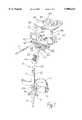
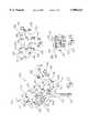
- FIG. 1is a front perspective view of the extramedullary alignment guide, a template and one embodiment of the adjustable milling base assembly of this invention.
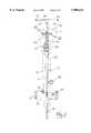
- FIG. 2is a front view of the extramedullary alignment guide and the reference guide shown with respect to a tibia (shown in broken lines).
- FIG. 3is a side view of the reference guide and alignment guide showing the position of the reference guide with respect to a tibial head.
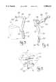
- FIG. 4is a perspective view of the reference guide.
- FIG. 5is a top view of the reference guide and alignment guide showing the position of the reference guide with respect to a tibial head (shown in broken lines).
- FIG. 6is a top view of the sizing gauge shown in relation to a tibial head (shown in broken lines).
- FIG. 7is a side view of the sizing instrument shown in relation to a tibial head (shown in broken lines).
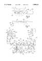
- FIG. 8is a perspective view of the milling depth gauge of this invention.
- FIG. 9is a front view of the milling depth gauge.
- FIG. 10is a sectional view of the milling depth gauge taken along line 10--10 of FIG. 9.
- FIG. 11is an exploded view of the milling depth gauge.
- FIG. 12is a top view of a template seated atop the adjustable milling base assembly and alignment guide.
- FIG. 13is a partial front view of the template, adjustable milling base assembly and the upper portion of the alignment guide connected to the tibia (shown in broken lines).
- FIG. 14is a front view of the depth gauge positioned on a template and adjustable milling base assembly.
- FIG. 15is an exploded view of the adjustable milling base assembly.
- FIG. 16is a perspective view of a deflector shield attached to the adjustable milling base assembly.
- FIG. 17shows a second embodiment of the adjustable milling base assembly.
- FIG. 18is a top view of the adjustable milling base assembly of FIG. 17.
- FIG. 19is a sectional view of the adjustable milling base assembly taken along line 19--19 of FIG. 18.
- FIG. 20is a front view of the adjustable milling base of FIG. 17 with the base shifted to one side of the slide head.
- FIG. 21is a side view of the adjustable milling base of FIG. 17 with the base shifted away from the slide head.
- FIG. 22is a front view of the adjustable milling base of FIG. 17 with the base shifted to the opposite side of the slide head.
- FIG. 23is a side view of the adjustable milling base of FIG. 17 with the base shifted to abut the slide head.
- FIGS. 1-16show the tibial milling guide system of this invention.
- the tibial milling guide systemhas a variety of separate components including: an extramedullary tibial alignment guide 10; an adjustment milling base assembly 40; a milling template 80; a sizing gauge 90; and a milling depth gauge 100. All of the separate components are constructed of suitable materials that allow the components to be reusable and sterilized.
- extramedullary tibial alignment guide 10is of conventional telescoping design and includes an extensible upper member 20 shiftably fitted within a tubular lower member 12.
- Lower member 12has a longitudinal slot 13 and terminates in a pointed end 14.
- Lower member 12includes an adjustable plate 16 and connecting strap 17 for securing the lower member to the patient's lower leg.
- Plate 16is arcuate to conform to the outer contour of a patient's lower leg adjacent the ankle.
- Plate 16includes a perpendicular slide member 18. Slide member 18 extends laterally through lower member 12 and is secured by lock screw 27 to adjustably connect plate 16 and lower member 12.
- Upper member 20has a solid elongated body which terminates in a perpendicular mounting bracket 22. Bracket 22 has a plurality of bores 23 for accepting bone screws 16 which secure upper member 20 to the proximal tibia (shown in FIGS. 13, 14, and 16). Upper member 20 also has a central opening 21. A vertical adjustment knob 24 is supported within opening 21, as shown in FIG. 1. Vertical adjustment knob 24 has a threaded longitudinal through bore (not shown). A semicircular longitudinal bore 25 extends through upper member 20 from its upper end to opening 21. Upper member 20 is secured within lower member 12 by a length adjustment lock screw 28 which extends through a groove 13 and threads into a bore in upper member 20.
- the length and attitude of alignment guide 10can be adjusted and secured using lock screws 27 and 28.
- the length of alignment guide 10can be adjusted by selectively telescoping upper member 20 inside lower member 12 and securing them with lock screw 28.
- the attitude of alignment guide 10 to tibia 2can also be adjusted by spacing shin plate 16 from the lower member 12 and securing them with lock screw 27.
- the adjustment of the attitude of the alignment guideestablishes the anterior-posterior slope for the milling guide.
- alignment guide 10also includes a detachable proximal tibial reference guide 30.
- Reference guide 30includes a neck 32 and a T-shaped member 36.
- T-shaped member 36extends perpendicularly from the upper end of neck 32.
- T-shaped member 36is substantially planar and includes two lateral arms 37 extending from a central leg 38 and a centering point 39.
- the lower portion of neck 32is adapted to be fitted within bore 25 of alignment guide 10 and has a semicircular cross section with a flat face 33 and a threaded distal end 34.
- reference guide 30is inserted into bore 25 of upper member 20 with threaded end 34 turned into vertical adjustment knob 24. Consequently, rotating the vertical adjustment knob extends and retracts the reference guide within the alignment guide to adjustably space the T-shaped member above the articular surface of the tibial head.
- adjustable milling base assembly 40includes a T-shaped slider 50 and a shiftable base 60.
- Slide 50includes a laterally elongated head 54 and an elongated neck 52 extending perpendicularly from head 54.
- Neck 52is adapted to be fitted within bore 25 of alignment guide 10 and has a semicircular cross section and a threaded distal end 53.
- Slide head 54has an elongated lateral opening 43 which extends in an anterior-posterior direction relative to the tibia.
- Slide head 54has a lateral channel 57 defined by an upper posterior flange 55 and a lower posterior flange 56.
- a slide plate 58extends from the posterior side of slide head 54 adjacent lower flange 56.
- a pair of aligned slots 59are defined in slide plate 58 as shown in FIG. 15.
- Shiftable base 60has a slightly arcuate posterior face to conform to the anterior contour of tibial head 3 just below the knee joint.
- Base 60also has a burr opening 61 to allow the burr 7 of the milling device to pass.
- the anterior face of base 60has a raised lateral shoulder 62.
- Transverse through bores 63are formed in base 60 across shoulder 62 for accommodating bone screws 42 to secure base 60 when properly positioned against the tibia.
- Base 60is shiftably connected to slide 50.
- Base 60is seated atop slide plate 58 with shoulder 62 fitted within channel 57.
- Stop pins 48are inserted into holes (not shown) in the lower face of head 54 to protrude into slots 59 of slide plate 58. Stop pins 48 limit the longitudinal movement base 60 along slide head 54.
- bore 63aligns with opening 43 in slide head 54 when base 60 is connected to slide 50. The width of opening 43 is sufficient to allow access to bore 63 when base 60 is shifted to either lateral extreme.
- base 60also has a pair of template mounting bores 70 and a release mechanism for securing template 80 to base 60.
- the release mechanismincludes two depressible release cylinders 72 shiftably housed within two end bores 71.
- Each release cylinder 72has a lateral through bore 74 normal to its axis and an annular recess 73.
- Lateral bores 74 of release cylinders 72have substantially identical diameters as mounting bores 70 and substantially align with mounting bore 70 when release cylinders 72 are inserted into end bore 71.
- Lock pin 75extends through a bore 77 in the posterior face of base 60 and into annular release 73 to prevent cylinders 72 from being removed from end bore 71.
- Springs 76are inserted into each end bore 71 to urge its release cylinder 72 out from end bore 71, which displaces the alignment of lateral bore 74 and mounting bore 70. Depressing cylinder 72 into end bore 71 axially realigns lateral bores 74 and mounting bores 70.
- milling base assembly 40is extensibly connected to alignment guide 10.
- Neck 52 of slide 50is inserted into bore 25 of upper member 20 with threaded end 53 turned into vertical adjustment knob 24. Consequently, rotating vertical adjustment knob 24 extends and retracts milling base assembly 40 within upper member 20.
- the semicircular cross section and flat face of neck 52keeps the milling base assembly properly aligned within bore 25 when fitted to the alignment guide.
- adjustable milling base 40may include a detachable debris shield 78.
- Shield 78has an arcuate transparent body with a pair of side holes 79. Once milling template 80 is attached to the milling base assembly 40, shield 78 can be mounted to base 60 with the protruding ends of release cylinders 72 extending through side holes 79. The resilience of the shield body holds the shield in place. The shield covers the front of the milling base assembly to limit the scattering of tissue debris discharged during the milling process.
- Milling template 80is generally planar and has an upper reference surface 82 and a lower surface 83. Template 80 also has a fixed track 84 and a burr opening 85 for guiding the burr 7 (FIG. 16) of the milling device. Track 84 is shaped so that a portion of the path that burr 7 cuts overlaps other portions of the path to cut a continuous planar surface. Burrs having different diameters may require different track configurations. Reference surface 82 controls the depth of the cut.
- the burrmay be guided to cut an area that is within the periphery of the template or an area that extends beyond the template, it is preferable that the periphery of the template correspond to the outer limits of the path cut by the burr to allow an operator to determine the precise location where tissues will be cut. It is also preferable to provide a variety of guides to accommodate a variety of bone sizes and shapes and a variety of shape cut areas.
- the exemplary guide shownprovides an uncut posterior region as would be suitable for a posterior crucial ligament retaining tibial prosthesis.
- Two mounting posts 86extend from the lower surface 83 for connecting template 80 within mounting bores 70 of base 60.
- Mounting posts 86extend through mounting bores 70 and lateral bore 74 of release cylinder 72. When mounting posts 86 are inserted into base 60, the tension of spring 76 urges release cylinder 72 laterally against mounting posts 86 to secure the template 80 to base 60.
- the procedure using the tibial milling guide system of this inventionbegins with preparing the knee joint and exposing the tibial head 3.
- Alignment guide 10is first fitted with reference guide 30 as shown in FIG. 2.
- the lower member 12 of alignment guide 10is secured to the patient's lower leg.
- Plate 16abuts the front of the shin and is secured by strap 17 with point end 14 positioned at the base of the ankle.
- the length of the alignment instrumentcan be adjusted by lock screw 28.
- Upper member 20is extended or retracted such that bracket 22 is positioned just below the knee joint.
- Reference guide 30is used to properly position alignment guide 10 along the lower leg. As shown in FIG. 5, rotational alignment is determined by positioning alignment guide 10 so that centering point 39 generally overlies the center of tibial head 3 and each arm 37 of T-shaped member 36 generally extends equidistantly beyond a lateral extremity of tibial head 3. Planar T-shaped member 36 also provides a reference plane for adjusting the attitude of the alignment guide using lock screw 27 so that the proper posterior slope can be established.
- Reference guide 30can be spaced toward and away from the tibial head using vertical adjustment knob 24 to allow improved visual alignment. Once properly aligned, bone screws 26 are driven through bores 23 to secure upper member 20 of alignment guide 10 to tibia 2 as shown in FIG. 2.
- reference guide 30With alignment guide 10 properly secured to the tibia and lower leg, reference guide 30 is removed and adjustable milling base 40 is fitted to alignment guide 10. Neck 52 is inserted into bore 25 and threaded end 53 is turned into vertical adjustment knob 24 until milling base assembly 40 is at the appropriate height above articular surface 4. With milling base assembly 40 positioned at the proper height, the surgeon can manually shift base 60 laterally with respect to slide 50 to center base 60 with articular surface 4. Once base 60 is properly positioned, base 60 is secured in place by bone screws 26 which are inserted through opening 43 and bores 63 and turned into tibia 2. After base 60 is secured to the tibia, template 80 is mounted to base 60. Mounting posts 86 are seated within mounting bores 70 with release cylinder 72 locking template 80 to base 60. As shown in FIG. 16, burr opening 85 of template 80 aligns with burr opening 61 of base 60 to allow the burr 7 of a milling device to pass. Optionally, shield 78 can be attached to base 60 at this point.
- FIGS. 6 and 7show an L-shaped sizing gauge 90 used for selecting the appropriate template size to accommodate the tibial head and the articular surface to be cut.
- Sizing gauge 90includes a flat elongated bar 92 and a down-turned arm 94 which extends perpendicularly from one end of bar 92. As shown in FIG. 7, a contact finger 95 extends perpendicularly from arm 94 and parallels bar 92.
- the upper surface of bar 92is delineated with a set of sizing indicia 96 which correspond with various sizes of templates.
- bar 92has a longitudinal row of closely spaced centering holes 93 positioned between sizing indicia 96 and arm 94. Each centering hole 93 is marked with a corresponding sizing indicia 97 on the upper surface of bar 92.
- sizing gauge 90is placed atop the exposed tibial head 3, as shown in FIGS. 6 and 7. Bar 92 is manually held parallelly across with contact finger 95 engaging either the lateral or medial side of tibial head 3. With the sizing gauge so positioned, the surgeon can obtain a reading to determine the appropriate template size by looking down upon the instrument as in FIG. 6. The centering hole which aligns directly over the exposed tibial head provides a size indication. A second reading is obtained from the sizing mark which overlies the lateral extremity of the tibial head. The sizing reading from the centering holes should approximately correspond to the sizing reading taken from the outside of the tibial head.
- FIGS. 8-11 and 14show the milling depth gauge 100.
- Depth gauge 100includes three components: a body 102, slide 112 and lock pin 111.
- body 102is shaped as shown in FIGS. 8-11.
- the rear side of body 102includes a semicircular rear face 103 which extends substantially the entire length of body 102.
- the front side of body 102includes a curved lower face 104 and a flat upper face 105.
- Lower face 104terminates in a flat lip or intermediate face 106 which extends across the diameter of body 102.
- Body 102also has a circular bottom face 107 and a semicircular top face 108.
- a rectangular central cavity 110extends axially through body 102 between top face 108 and bottom face 107.
- a bore 109extends from rear face 103 into cavity 110.
- Slide 112includes a ruled bar 114 and a probe 118 extending axially from one end of the bar.
- Ruled bar 114has a rectangular cross section dimensioned to accommodate cavity 110.
- the front of ruled bar 114is delineated with indicia 116.
- a longitudinal slot 115is formed on the rear side of ruled bar 114.
- Probe 118has a contact end 119.
- Slide 112is fitted within body 102 for shiftable longitudinal movement within cavity 110.
- Ruled bar 114extends along upper face 105 partially above lip 106 and contact end 119 extends below bottom face 107.
- Lock pin 111is fitted into bore 109 and protrudes into slot 115. The movement of slide 112 is limited by pin 111 contacting the upper and lower end of slot 115.
- FIG. 14shows depth indicator 100 used in conjunction with alignment guide 10, milling base assembly 40 and template 80 to indicate amount of bone stock which will be removed during milling.
- Depth gauge 100is placed on reference surface 82 of template 80 with probe 118 extending through track 84.
- Slide 112is manually pushed downward through cavity 110 to contact articular surface 4 of tibial head 3.
- ruled bar 114extends above lip 106 whereby a reading can be taken.
- Depth gauge 100can be positioned at any point along track 84 in order to located the lowest point of the articular surface thereby determining the maximum cut depth.
- FIGS. 17-23show a second preferred embodiment of the adjustable milling base 120.
- Milling base 120operates substantially as described above but allows for bi-directional movement of the base.
- Adjustable milling base assembly 120includes a T-shaped slide 130 and a shiftable base 140 connected by a pair of couplers 122.
- Slide 130includes a laterally elongated head 134 and an elongated neck 132 extending perpendicularly from head 134.
- Neck 132is adapted to be fitted within bore 25 of alignment guide 10.
- Neck 132has a semi-circular cross section with a flat face 131 and a threaded distal end 133.
- Neck 132 of slide 130is inserted into bore 25 of upper member 20 with threaded end 133 turned into vertical adjustment knob 24. Consequently, rotating vertical adjustment knob 24 extends and retracts milling base assembly 120 within upper member 20.
- the semi-circular cross section and flat face 131 of neck 132keeps the milling base assembly properly aligned within bore 25 when fitted
- Head 134has two elongated openings 135 formed as shown in FIGS. 17, 20 and 22. Openings 135 are longitudinally aligned across head 134 and extend through head 134. Head 134 has two upward arms 136 which terminate in oppositely facing rails 138 which parallel head 134. As shown in FIGS. 17 and 19, rails 138 have a generally square cross section.
- Shiftable base 140has a slightly arcuate posterior face to conform to the anterior contour of the tibial head just below the knee joint.
- Base 140also has a bur opening 141 to allow the burr of the milling device to pass.
- Two posts 142extend perpendicularly from the anterior face of base 140. Each post 142 terminates in a raised annular lip 143.
- Four transverse bores 145are formed in base 140 and extend from the anterior face to the posterior face along the lower edge of the base. As described in the first embodiment, bores 145 accommodate bone screws (not shown) to secure base 140 when properly positioned against the tibia.
- Base 140is shiftably connected to slide 130 by a pair of couplers 122.
- Each coupler 122has a generally square longitudinal through bore 123 dimensioned to accommodate rails 138 and a cylindrical lateral through bore 125 dimensioned to shiftably accommodate posts 142.
- Couplers 122ride on rails 138 for longitudinal movement along head 134 as shown in FIGS. 20 and 22.
- Posts 142slide within bores 125 to allow base 140 to move laterally toward and away from slide 130 as shown in FIGS. 21 and 23.
- the connection of base 140 to slide 130 by couplers 122allows bi-directional movement of the base with respect to the slide in a plane parallel to the articular surface of the tibial head. As shown in FIGS.
- bores 145 in base 140align with openings 135 in slide head 134 to accept the bone-screws which secure the base to the tibia.
- the width of opening 135is sufficient to allow access to bore 145 when the base is shifted to either lateral extreme of the slide head.
- Base 140also has a pair of template mounting bores 150 and a conventional release mechanism for securing the template to the base, preferably as described for the first embodiment.
- the release mechanismincludes two depressible release cylinders 152 shiftably housed within two end bores.
- Each release cylinder 152has a lateral through bore 154 normal to its axis.
- Lateral bores 154 of release cylinders 152have substantially identical diameters as mounting bores 150 and align with mounting bores 150 when release cylinders 152 are inserted into end bores.
- a spring(not shown) is inserted into each end bore to urge its release cylinder 152 out from its end bore, which displaces the alignment of lateral bore 154 and mounting bore 150 as shown in FIG. 18. Depressing cylinders 154 into their end bores axially realigns lateral bores 154 and mounting bores 150.
Landscapes
- Health & Medical Sciences (AREA)
- Surgery (AREA)
- Life Sciences & Earth Sciences (AREA)
- Biomedical Technology (AREA)
- Medical Informatics (AREA)
- Orthopedic Medicine & Surgery (AREA)
- Oral & Maxillofacial Surgery (AREA)
- Engineering & Computer Science (AREA)
- Dentistry (AREA)
- Heart & Thoracic Surgery (AREA)
- Nuclear Medicine, Radiotherapy & Molecular Imaging (AREA)
- Molecular Biology (AREA)
- Animal Behavior & Ethology (AREA)
- General Health & Medical Sciences (AREA)
- Public Health (AREA)
- Veterinary Medicine (AREA)
- Surgical Instruments (AREA)
- Prostheses (AREA)
- Milling Processes (AREA)
Abstract
Description
Claims (16)
Priority Applications (14)
| Application Number | Priority Date | Filing Date | Title |
|---|---|---|---|
| US08/242,987US5908424A (en) | 1994-05-16 | 1994-05-16 | Tibial milling guide system |
| CA002148429ACA2148429C (en) | 1994-05-16 | 1995-05-02 | Tibial milling guide system |
| AU17920/95AAU698514B2 (en) | 1994-05-16 | 1995-05-08 | Tibial milling guide system |
| JP11477895AJP3739828B2 (en) | 1994-05-16 | 1995-05-12 | Tibial milling guide device |
| ES03009425TES2260539T3 (en) | 1994-05-16 | 1995-05-16 | DEPTH CALIBRATOR FOR BONE MILLING. |
| EP03009427AEP1329200A1 (en) | 1994-05-16 | 1995-05-16 | Reference guide for tibial milling |
| EP95201279AEP0682916B1 (en) | 1994-05-16 | 1995-05-16 | Bone milling guide system |
| ES95201279TES2206477T3 (en) | 1994-05-16 | 1995-05-16 | GUIDING SYSTEM FOR BONE MILLING. |
| ES03009426TES2219634T3 (en) | 1994-05-16 | 1995-05-16 | GUIDING SYSTEM FOR TIBIAL MILLING. |
| EP03009425AEP1329198B1 (en) | 1994-05-16 | 1995-05-16 | Bone milling depth guage |
| DE69531803TDE69531803T2 (en) | 1994-05-16 | 1995-05-16 | Guide system for milling bones |
| DE69534927TDE69534927T2 (en) | 1994-05-16 | 1995-05-16 | Guide system for milling bones |
| EP03009426AEP1329199B1 (en) | 1994-05-16 | 1995-05-16 | Bone size measuring apparatus |
| DE69533009TDE69533009T2 (en) | 1994-05-16 | 1995-05-16 | Device for bone size determination |
Applications Claiming Priority (1)
| Application Number | Priority Date | Filing Date | Title |
|---|---|---|---|
| US08/242,987US5908424A (en) | 1994-05-16 | 1994-05-16 | Tibial milling guide system |
Publications (1)
| Publication Number | Publication Date |
|---|---|
| US5908424Atrue US5908424A (en) | 1999-06-01 |
Family
ID=22916894
Family Applications (1)
| Application Number | Title | Priority Date | Filing Date |
|---|---|---|---|
| US08/242,987Expired - LifetimeUS5908424A (en) | 1994-05-16 | 1994-05-16 | Tibial milling guide system |
Country Status (7)
| Country | Link |
|---|---|
| US (1) | US5908424A (en) |
| EP (4) | EP1329198B1 (en) |
| JP (1) | JP3739828B2 (en) |
| AU (1) | AU698514B2 (en) |
| CA (1) | CA2148429C (en) |
| DE (3) | DE69533009T2 (en) |
| ES (3) | ES2219634T3 (en) |
Cited By (107)
| Publication number | Priority date | Publication date | Assignee | Title |
|---|---|---|---|---|
| US6228091B1 (en)* | 1998-10-13 | 2001-05-08 | Stryker Technologies Corporation | Methods and tools for tibial intermedullary revision surgery and associated tibial components |
| KR100407894B1 (en)* | 2001-09-07 | 2003-12-01 | 한국과학기술원 | A Gauge Device For Surgical Replacing Operation Of A Coxa |
| US20040015173A1 (en)* | 2002-01-25 | 2004-01-22 | Irving John F. | Extramedullary fluoroscopic alignment guide |
| US20040039395A1 (en)* | 2002-05-24 | 2004-02-26 | Coon Thomas M. | Instruments for knee surgery and method of use |
| US6702821B2 (en) | 2000-01-14 | 2004-03-09 | The Bonutti 2003 Trust A | Instrumentation for minimally invasive joint replacement and methods for using same |
| US6758850B2 (en) | 2002-03-29 | 2004-07-06 | Depuy Orthopaedics, Inc. | Instruments and methods for flexion gap adjustment |
| US20040153066A1 (en)* | 2003-02-03 | 2004-08-05 | Coon Thomas M. | Apparatus for knee surgery and method of use |
| US20050070910A1 (en)* | 2001-08-10 | 2005-03-31 | Greg Keene | Tibial resection guide |
| US20050143745A1 (en)* | 2003-12-30 | 2005-06-30 | Medicinelodge, Inc. | Instruments and methods for preparing a joint articulation surface for an implant |
| US20050143731A1 (en)* | 2003-12-30 | 2005-06-30 | Medicinelodge, Inc. | Tibial condylar hemiplasty tissue preparation instruments and methods |
| US20060009854A1 (en)* | 2004-07-09 | 2006-01-12 | Medicinelodge, Inc. | Guide templates for surgical implants and related methods |
| US20060009776A1 (en)* | 2004-07-09 | 2006-01-12 | Medicinelodge, Inc. | Modular guide systems and related rasps and methods for resecting a joint articulation surface |
| US20060030944A1 (en)* | 2004-01-14 | 2006-02-09 | Haines Timothy G | Methods and apparatus for enhanced retention of prosthetic implants |
| US20060064108A1 (en)* | 2004-09-09 | 2006-03-23 | Blaylock Jeffrey C | Tibial sizing apparatus and method |
| US20060069443A1 (en)* | 2004-09-27 | 2006-03-30 | Deffenbaugh Daren L | Modular glenoid prosthesis and associated method |
| US20060069444A1 (en)* | 2004-09-27 | 2006-03-30 | Deffenbaugh Daren L | Glenoid augment and associated method |
| US20060074353A1 (en)* | 2004-09-27 | 2006-04-06 | Deffenbaugh Daren L | Glenoid instrumentation and associated method |
| US20060074430A1 (en)* | 2004-09-27 | 2006-04-06 | Deffenbaugh Daren L | Instrument for preparing an implant support surface and associated method |
| US20060089621A1 (en)* | 2004-03-18 | 2006-04-27 | Mike Fard | Bone mill and template |
| US20060149287A1 (en)* | 2003-03-11 | 2006-07-06 | Stephane Lavallee | Instrument for fixing the position of a cutting plane |
| US20060184176A1 (en)* | 2005-02-17 | 2006-08-17 | Zimmer Technology, Inc. | Tibial trialing assembly and method of trialing a tibial implant |
| US7104996B2 (en) | 2000-01-14 | 2006-09-12 | Marctec. Llc | Method of performing surgery |
| US20060241639A1 (en)* | 2005-04-18 | 2006-10-26 | Accin Corporation | Unicondylar knee instrument system |
| US20060276796A1 (en)* | 2005-05-26 | 2006-12-07 | Medicinelodge, Inc. | Milling system and methods for resecting a joint articulation surface |
| US20060293682A1 (en)* | 2005-06-10 | 2006-12-28 | Medicinelodge, Inc. | Milling system with guide paths and related methods for resecting a joint articulation surface |
| US20070233141A1 (en)* | 2006-02-15 | 2007-10-04 | Ilwhan Park | Arthroplasty devices and related methods |
| US20070233137A1 (en)* | 2006-02-15 | 2007-10-04 | Jai-Gon Seo | Tibia cutter |
| US20080195109A1 (en)* | 2007-02-13 | 2008-08-14 | Hunter Mark W | Navigated cut guide for total knee reconstruction |
| US20080234683A1 (en)* | 2007-03-16 | 2008-09-25 | Zimmer Technology, Inc. | Single plane anatomic referencing tissue preparation |
| US7481814B1 (en) | 2003-07-28 | 2009-01-27 | Biomet Manufacturing Corporation | Method and apparatus for use of a mill or reamer |
| US7488324B1 (en) | 2003-12-08 | 2009-02-10 | Biomet Manufacturing Corporation | Femoral guide for implanting a femoral knee prosthesis |
| US7510557B1 (en) | 2000-01-14 | 2009-03-31 | Bonutti Research Inc. | Cutting guide |
| US20090088763A1 (en)* | 2007-09-30 | 2009-04-02 | Aram Luke J | Customized Patient-Specific Bone Cutting Block with External Reference |
| US7608079B1 (en)* | 2004-03-05 | 2009-10-27 | Biomet Manufacturing Corp. | Unicondylar knee apparatus and system |
| US20100076441A1 (en)* | 2008-09-19 | 2010-03-25 | Zimmer, Inc. | Patello-femoral milling system |
| US7695479B1 (en) | 2005-04-12 | 2010-04-13 | Biomet Manufacturing Corp. | Femoral sizer |
| US7695520B2 (en) | 2006-05-31 | 2010-04-13 | Biomet Manufacturing Corp. | Prosthesis and implementation system |
| US7708741B1 (en) | 2001-08-28 | 2010-05-04 | Marctec, Llc | Method of preparing bones for knee replacement surgery |
| US20100161065A1 (en)* | 2008-12-23 | 2010-06-24 | Depuy Products, Inc. | Shoulder Prosthesis with Vault-Filling Structure having Bone-Sparing Configuration |
| US7780672B2 (en) | 2006-02-27 | 2010-08-24 | Biomet Manufacturing Corp. | Femoral adjustment device and associated method |
| US7789885B2 (en) | 2003-01-15 | 2010-09-07 | Biomet Manufacturing Corp. | Instrumentation for knee resection |
| US7799084B2 (en) | 2002-10-23 | 2010-09-21 | Mako Surgical Corp. | Modular femoral component for a total knee joint replacement for minimally invasive implantation |
| US7837690B2 (en) | 2003-01-15 | 2010-11-23 | Biomet Manufacturing Corp. | Method and apparatus for less invasive knee resection |
| US20100305488A1 (en)* | 2007-09-21 | 2010-12-02 | Depuy International Limited | Surgical instrument attachment |
| US20100331848A1 (en)* | 2009-05-29 | 2010-12-30 | Richard Michael Smith | Methods and Apparatus for Performing Knee Arthroplasty |
| US7887542B2 (en) | 2003-01-15 | 2011-02-15 | Biomet Manufacturing Corp. | Method and apparatus for less invasive knee resection |
| US7935151B2 (en) | 2001-03-05 | 2011-05-03 | Hudson Surgical Design, Inc. | Femoral prosthetic implant |
| US20110137424A1 (en)* | 2009-12-08 | 2011-06-09 | Depuy Products, Inc. | Shoulder Prosthesis Assembly having Glenoid Rim Replacement Structure |
| US7967822B2 (en) | 1994-09-02 | 2011-06-28 | Hudson Surgical Design, Inc. | Methods and apparatus for orthopedic implants |
| USD642263S1 (en) | 2007-10-25 | 2011-07-26 | Otismed Corporation | Arthroplasty jig blank |
| US20110208199A1 (en)* | 2002-06-21 | 2011-08-25 | Depuy Products, Inc. | Prosthesis Removal Cutting Guide, Cutting Tool and Method |
| US8021368B2 (en) | 2004-01-14 | 2011-09-20 | Hudson Surgical Design, Inc. | Methods and apparatus for improved cutting tools for resection |
| US8070752B2 (en) | 2006-02-27 | 2011-12-06 | Biomet Manufacturing Corp. | Patient specific alignment guide and inter-operative adjustment |
| US8114083B2 (en) | 2004-01-14 | 2012-02-14 | Hudson Surgical Design, Inc. | Methods and apparatus for improved drilling and milling tools for resection |
| US8160345B2 (en) | 2008-04-30 | 2012-04-17 | Otismed Corporation | System and method for image segmentation in generating computer models of a joint to undergo arthroplasty |
| US20120143200A1 (en)* | 2009-06-24 | 2012-06-07 | John Robert Honiball | Positioning guide and a femur bone cutting guide system |
| US8221430B2 (en) | 2007-12-18 | 2012-07-17 | Otismed Corporation | System and method for manufacturing arthroplasty jigs |
| US8265949B2 (en) | 2007-09-27 | 2012-09-11 | Depuy Products, Inc. | Customized patient surgical plan |
| US8311306B2 (en) | 2008-04-30 | 2012-11-13 | Otismed Corporation | System and method for image segmentation in generating computer models of a joint to undergo arthroplasty |
| US20130012941A1 (en)* | 2005-10-03 | 2013-01-10 | Smith & Nephew, Inc. | Locking instrument assembly |
| US8357111B2 (en) | 2007-09-30 | 2013-01-22 | Depuy Products, Inc. | Method and system for designing patient-specific orthopaedic surgical instruments |
| US8460302B2 (en) | 2006-12-18 | 2013-06-11 | Otismed Corporation | Arthroplasty devices and related methods |
| US8460303B2 (en) | 2007-10-25 | 2013-06-11 | Otismed Corporation | Arthroplasty systems and devices, and related methods |
| US8465548B2 (en) | 2010-11-24 | 2013-06-18 | DePuy Synthes Products, LLC | Modular glenoid prosthesis |
| US8480750B2 (en) | 2010-11-24 | 2013-07-09 | DePuy Synthes Products, LLC | Modular glenoid prosthesis |
| US8480679B2 (en) | 2008-04-29 | 2013-07-09 | Otismed Corporation | Generation of a computerized bone model representative of a pre-degenerated state and useable in the design and manufacture of arthroplasty devices |
| US8545509B2 (en) | 2007-12-18 | 2013-10-01 | Otismed Corporation | Arthroplasty system and related methods |
| US8551100B2 (en) | 2003-01-15 | 2013-10-08 | Biomet Manufacturing, Llc | Instrumentation for knee resection |
| US8603095B2 (en) | 1994-09-02 | 2013-12-10 | Puget Bio Ventures LLC | Apparatuses for femoral and tibial resection |
| US8617171B2 (en) | 2007-12-18 | 2013-12-31 | Otismed Corporation | Preoperatively planning an arthroplasty procedure and generating a corresponding patient specific arthroplasty resection guide |
| US8617170B2 (en) | 2010-09-29 | 2013-12-31 | DePuy Synthes Products, LLC | Customized patient-specific computer controlled cutting system and method |
| US8617175B2 (en) | 2008-12-16 | 2013-12-31 | Otismed Corporation | Unicompartmental customized arthroplasty cutting jigs and methods of making the same |
| US8715291B2 (en) | 2007-12-18 | 2014-05-06 | Otismed Corporation | Arthroplasty system and related methods |
| US8734455B2 (en) | 2008-02-29 | 2014-05-27 | Otismed Corporation | Hip resurfacing surgical guide tool |
| US8737700B2 (en) | 2007-12-18 | 2014-05-27 | Otismed Corporation | Preoperatively planning an arthroplasty procedure and generating a corresponding patient specific arthroplasty resection guide |
| US8740906B2 (en) | 2004-01-14 | 2014-06-03 | Hudson Surgical Design, Inc. | Method and apparatus for wireplasty bone resection |
| US8747410B2 (en) | 2010-10-26 | 2014-06-10 | Zimmer, Inc. | Patellar resection instrument with variable depth guide |
| US8777875B2 (en) | 2008-07-23 | 2014-07-15 | Otismed Corporation | System and method for manufacturing arthroplasty jigs having improved mating accuracy |
| US8801720B2 (en) | 2002-05-15 | 2014-08-12 | Otismed Corporation | Total joint arthroplasty system |
| US8900316B2 (en) | 2010-01-29 | 2014-12-02 | Smith & Nephew, Inc. | Cruciate-retaining knee prosthesis |
| US9017336B2 (en) | 2006-02-15 | 2015-04-28 | Otismed Corporation | Arthroplasty devices and related methods |
| US9078674B2 (en) | 2007-09-21 | 2015-07-14 | Depuy (Ireland) | Adjustable surgical instrument |
| US9138259B2 (en) | 2012-12-19 | 2015-09-22 | Biomet Sports Medicine, Llc | External tibial mill guide and method of use |
| US9168188B2 (en) | 2007-11-13 | 2015-10-27 | Orthopediatrics Corporation | Cast removal system |
| US9402637B2 (en) | 2012-10-11 | 2016-08-02 | Howmedica Osteonics Corporation | Customized arthroplasty cutting guides and surgical methods using the same |
| US20170000503A1 (en)* | 2015-06-30 | 2017-01-05 | Ryan C. Keefer | Orthopaedic surgical instrument system and method for surgically preparing a patient's bone |
| US9700329B2 (en) | 2006-02-27 | 2017-07-11 | Biomet Manufacturing, Llc | Patient-specific orthopedic instruments |
| US9730712B2 (en) | 2012-10-18 | 2017-08-15 | Smith & Nephew, Inc. | Alignment devices and methods |
| US9743935B2 (en) | 2011-03-07 | 2017-08-29 | Biomet Manufacturing, Llc | Patient-specific femoral version guide |
| US9795399B2 (en) | 2006-06-09 | 2017-10-24 | Biomet Manufacturing, Llc | Patient-specific knee alignment guide and associated method |
| US9913734B2 (en) | 2006-02-27 | 2018-03-13 | Biomet Manufacturing, Llc | Patient-specific acetabular alignment guides |
| US9968376B2 (en) | 2010-11-29 | 2018-05-15 | Biomet Manufacturing, Llc | Patient-specific orthopedic instruments |
| US10159498B2 (en) | 2008-04-16 | 2018-12-25 | Biomet Manufacturing, Llc | Method and apparatus for manufacturing an implant |
| US10172627B2 (en) | 2015-06-29 | 2019-01-08 | Smith & Nephew, Inc. | Graft placement system and method |
| US10206695B2 (en) | 2006-02-27 | 2019-02-19 | Biomet Manufacturing, Llc | Femoral acetabular impingement guide |
| US10278711B2 (en) | 2006-02-27 | 2019-05-07 | Biomet Manufacturing, Llc | Patient-specific femoral guide |
| US10390845B2 (en) | 2006-02-27 | 2019-08-27 | Biomet Manufacturing, Llc | Patient-specific shoulder guide |
| US10426492B2 (en) | 2006-02-27 | 2019-10-01 | Biomet Manufacturing, Llc | Patient specific alignment guide with cutting surface and laser indicator |
| US10507029B2 (en) | 2006-02-27 | 2019-12-17 | Biomet Manufacturing, Llc | Patient-specific acetabular guides and associated instruments |
| US10582934B2 (en) | 2007-11-27 | 2020-03-10 | Howmedica Osteonics Corporation | Generating MRI images usable for the creation of 3D bone models employed to make customized arthroplasty jigs |
| US10603179B2 (en) | 2006-02-27 | 2020-03-31 | Biomet Manufacturing, Llc | Patient-specific augments |
| US10722310B2 (en) | 2017-03-13 | 2020-07-28 | Zimmer Biomet CMF and Thoracic, LLC | Virtual surgery planning system and method |
| US10743937B2 (en) | 2006-02-27 | 2020-08-18 | Biomet Manufacturing, Llc | Backup surgical instrument system and method |
| US11051829B2 (en) | 2018-06-26 | 2021-07-06 | DePuy Synthes Products, Inc. | Customized patient-specific orthopaedic surgical instrument |
| US11534313B2 (en) | 2006-02-27 | 2022-12-27 | Biomet Manufacturing, Llc | Patient-specific pre-operative planning |
| US11554019B2 (en) | 2007-04-17 | 2023-01-17 | Biomet Manufacturing, Llc | Method and apparatus for manufacturing an implant |
| US11666346B2 (en) | 2007-03-23 | 2023-06-06 | Xiros Limited | Surgical templates |
Families Citing this family (17)
| Publication number | Priority date | Publication date | Assignee | Title |
|---|---|---|---|---|
| CA2126627C (en)* | 1993-07-06 | 2005-01-25 | Kim C. Bertin | Femoral milling instrumentation for use in total knee arthroplasty with optional cutting guide attachment |
| US5474559A (en)* | 1993-07-06 | 1995-12-12 | Zimmer, Inc. | Femoral milling instrumentation for use in total knee arthroplasty with optional cutting guide attachment |
| US5643272A (en)* | 1994-09-02 | 1997-07-01 | Hudson Surgical Design, Inc. | Method and apparatus for tibial resection |
| US5540696A (en)* | 1995-01-06 | 1996-07-30 | Zimmer, Inc. | Instrumentation for use in orthopaedic surgery |
| ES2553715T3 (en) | 2000-03-10 | 2015-12-11 | Smith & Nephew, Inc. | Apparatus for use in arthroplasty in a knee joint |
| US8211113B2 (en) | 2002-06-21 | 2012-07-03 | Depuy Products, Inc. | Prosthesis cutting guide, cutting tool and method |
| US20030236522A1 (en) | 2002-06-21 | 2003-12-25 | Jack Long | Prosthesis cavity cutting guide, cutting tool and method |
| US7815645B2 (en) | 2004-01-14 | 2010-10-19 | Hudson Surgical Design, Inc. | Methods and apparatus for pinplasty bone resection |
| US7857814B2 (en) | 2004-01-14 | 2010-12-28 | Hudson Surgical Design, Inc. | Methods and apparatus for minimally invasive arthroplasty |
| GB0426002D0 (en) | 2004-11-26 | 2004-12-29 | Depuy Int Ltd | A burr guide assembly |
| US7740593B2 (en) | 2005-12-09 | 2010-06-22 | Senorx, Inc | Guide block for biopsy or surgical devices |
| JP4796943B2 (en)* | 2006-11-20 | 2011-10-19 | 日本メディカルマテリアル株式会社 | Osteotomy guide instrument for proximal tibia |
| GB0803510D0 (en)* | 2008-02-27 | 2008-04-02 | Depuy Orthopaedie Gmbh | Cutting guide |
| US8821504B2 (en) | 2009-11-20 | 2014-09-02 | Zimmer Knee Creations, Inc. | Method for treating joint pain and associated instruments |
| EP2501303B1 (en)* | 2009-11-20 | 2020-02-12 | Zimmer Knee Creations, Inc. | Navigation and positioning instruments for joint repair |
| CA2831840C (en) | 2011-02-22 | 2017-08-22 | Knee Creations, Llc | Navigation and positioning systems and guide instruments for joint repair |
| US9386998B2 (en)* | 2011-10-27 | 2016-07-12 | Smith & Nephew, Inc. | Devices and methods for performing knee arthroplasty |
Citations (25)
| Publication number | Priority date | Publication date | Assignee | Title |
|---|---|---|---|---|
| US4457307A (en)* | 1982-08-20 | 1984-07-03 | Stillwell William T | Bone cutting device for total knee replacement |
| US4524766A (en)* | 1982-01-07 | 1985-06-25 | Petersen Thomas D | Surgical knee alignment method and system |
| US4567886A (en)* | 1983-01-06 | 1986-02-04 | Petersen Thomas D | Flexion spacer guide for fitting a knee prosthesis |
| US4574794A (en)* | 1984-06-01 | 1986-03-11 | Queen's University At Kingston | Orthopaedic bone cutting jig and alignment device |
| US4625405A (en)* | 1984-07-02 | 1986-12-02 | Deeco, Inc. | Cast cutter |
| US4721104A (en)* | 1985-12-02 | 1988-01-26 | Dow Corning Wright Corporation | Femoral surface shaping apparatus for posterior-stabilized knee implants |
| US4841975A (en)* | 1987-04-15 | 1989-06-27 | Cemax, Inc. | Preoperative planning of bone cuts and joint replacement using radiant energy scan imaging |
| US4935023A (en)* | 1989-01-09 | 1990-06-19 | Dow Corning Wright | Femoral surface shaping guide for knee implants |
| US4938762A (en)* | 1987-12-16 | 1990-07-03 | Protek Ag | Reference system for implantation of condylar total knee prostheses |
| US4952213A (en)* | 1989-02-03 | 1990-08-28 | Boehringer Mannheim Corporation | Tibial cutting guide |
| US5002547A (en)* | 1987-02-07 | 1991-03-26 | Pfizer Hospital Products Group, Inc. | Apparatus for knee prosthesis |
| US5007912A (en)* | 1990-05-30 | 1991-04-16 | Albrektsson Bjoern | Arrangement for fixing a knee-joint in defined positions and for positional control of instruments for replacing the knee-joint with a prosthesis |
| US5035699A (en)* | 1990-01-09 | 1991-07-30 | Dow Corning Wright | Patella track cutter and guide |
| US5049149A (en)* | 1988-12-14 | 1991-09-17 | Joachim Schmidt | Sawing gauge system |
| US5098436A (en)* | 1991-03-07 | 1992-03-24 | Dow Corning Wright Corporation | Modular guide for shaping of femur to accommodate intercondylar stabilizing housing and patellar track of implant |
| US5141513A (en)* | 1990-05-04 | 1992-08-25 | John Fortune | Surgical template |
| US5176684A (en)* | 1992-02-20 | 1993-01-05 | Dow Corning Wright | Modular shaping and trial reduction guide for implantation of posterior-stabilized femoral prosthesis and method of using same |
| US5190547A (en)* | 1992-05-15 | 1993-03-02 | Midas Rex Pneumatic Tools, Inc. | Replicator for resecting bone to match a pattern |
| US5197944A (en)* | 1992-03-30 | 1993-03-30 | Smith & Nephew Richards Inc. | Ankle clamp |
| US5207680A (en)* | 1992-05-11 | 1993-05-04 | Zimmer, Inc. | Front milling guide for use in orthopaedic surgery |
| US5250050A (en)* | 1987-02-07 | 1993-10-05 | Pfizer Hospital Products Group, Inc. | Apparatus for knee prosthesis |
| US5304181A (en)* | 1990-01-08 | 1994-04-19 | Caspari Richard B | Methods and apparatus for arthroscopic prosthetic knee replacement |
| US5306276A (en)* | 1991-12-10 | 1994-04-26 | Zimmer, Inc. | Tibial resector guide |
| US5344423A (en)* | 1992-02-06 | 1994-09-06 | Zimmer, Inc. | Apparatus and method for milling bone |
| US5417695A (en)* | 1992-07-27 | 1995-05-23 | Pfizer Hospital Products Group, Inc. | Instrumentation for preparing a distal femur |
Family Cites Families (6)
| Publication number | Priority date | Publication date | Assignee | Title |
|---|---|---|---|---|
| CH127308A (en)* | 1927-06-11 | 1928-08-16 | Arthur Borel Maurice | Tooling for depth measurement. |
| DE2536592A1 (en)* | 1975-08-16 | 1977-02-24 | Buecherer Werner | Demonstration vernier calipers used as teaching aid - are fitted with interchangeable vernier scale and interchangeable components for easy dismantling |
| GB1582622A (en)* | 1978-02-04 | 1981-01-14 | Servier Nederland Bv | Measuring device for the width of human femur condyles |
| US4759350A (en)* | 1986-10-17 | 1988-07-26 | Dunn Harold K | Instruments for shaping distal femoral and proximal tibial surfaces |
| US5235988A (en)* | 1991-07-15 | 1993-08-17 | United States Surgical Corporation | Device for evaluating surface contour |
| GB9213766D0 (en)* | 1992-06-29 | 1992-08-12 | Minnesota Mining & Mfg | Artificial knee joints |
- 1994
- 1994-05-16USUS08/242,987patent/US5908424A/ennot_activeExpired - Lifetime
- 1995
- 1995-05-02CACA002148429Apatent/CA2148429C/ennot_activeExpired - Fee Related
- 1995-05-08AUAU17920/95Apatent/AU698514B2/ennot_activeCeased
- 1995-05-12JPJP11477895Apatent/JP3739828B2/ennot_activeExpired - Lifetime
- 1995-05-16EPEP03009425Apatent/EP1329198B1/ennot_activeExpired - Lifetime
- 1995-05-16ESES03009426Tpatent/ES2219634T3/ennot_activeExpired - Lifetime
- 1995-05-16EPEP95201279Apatent/EP0682916B1/ennot_activeExpired - Lifetime
- 1995-05-16EPEP03009426Apatent/EP1329199B1/ennot_activeExpired - Lifetime
- 1995-05-16ESES03009425Tpatent/ES2260539T3/ennot_activeExpired - Lifetime
- 1995-05-16DEDE69533009Tpatent/DE69533009T2/ennot_activeExpired - Lifetime
- 1995-05-16ESES95201279Tpatent/ES2206477T3/ennot_activeExpired - Lifetime
- 1995-05-16DEDE69534927Tpatent/DE69534927T2/ennot_activeExpired - Lifetime
- 1995-05-16EPEP03009427Apatent/EP1329200A1/ennot_activeCeased
- 1995-05-16DEDE69531803Tpatent/DE69531803T2/ennot_activeExpired - Lifetime
Patent Citations (25)
| Publication number | Priority date | Publication date | Assignee | Title |
|---|---|---|---|---|
| US4524766A (en)* | 1982-01-07 | 1985-06-25 | Petersen Thomas D | Surgical knee alignment method and system |
| US4457307A (en)* | 1982-08-20 | 1984-07-03 | Stillwell William T | Bone cutting device for total knee replacement |
| US4567886A (en)* | 1983-01-06 | 1986-02-04 | Petersen Thomas D | Flexion spacer guide for fitting a knee prosthesis |
| US4574794A (en)* | 1984-06-01 | 1986-03-11 | Queen's University At Kingston | Orthopaedic bone cutting jig and alignment device |
| US4625405A (en)* | 1984-07-02 | 1986-12-02 | Deeco, Inc. | Cast cutter |
| US4721104A (en)* | 1985-12-02 | 1988-01-26 | Dow Corning Wright Corporation | Femoral surface shaping apparatus for posterior-stabilized knee implants |
| US5002547A (en)* | 1987-02-07 | 1991-03-26 | Pfizer Hospital Products Group, Inc. | Apparatus for knee prosthesis |
| US5250050A (en)* | 1987-02-07 | 1993-10-05 | Pfizer Hospital Products Group, Inc. | Apparatus for knee prosthesis |
| US4841975A (en)* | 1987-04-15 | 1989-06-27 | Cemax, Inc. | Preoperative planning of bone cuts and joint replacement using radiant energy scan imaging |
| US4938762A (en)* | 1987-12-16 | 1990-07-03 | Protek Ag | Reference system for implantation of condylar total knee prostheses |
| US5049149A (en)* | 1988-12-14 | 1991-09-17 | Joachim Schmidt | Sawing gauge system |
| US4935023A (en)* | 1989-01-09 | 1990-06-19 | Dow Corning Wright | Femoral surface shaping guide for knee implants |
| US4952213A (en)* | 1989-02-03 | 1990-08-28 | Boehringer Mannheim Corporation | Tibial cutting guide |
| US5304181A (en)* | 1990-01-08 | 1994-04-19 | Caspari Richard B | Methods and apparatus for arthroscopic prosthetic knee replacement |
| US5035699A (en)* | 1990-01-09 | 1991-07-30 | Dow Corning Wright | Patella track cutter and guide |
| US5141513A (en)* | 1990-05-04 | 1992-08-25 | John Fortune | Surgical template |
| US5007912A (en)* | 1990-05-30 | 1991-04-16 | Albrektsson Bjoern | Arrangement for fixing a knee-joint in defined positions and for positional control of instruments for replacing the knee-joint with a prosthesis |
| US5098436A (en)* | 1991-03-07 | 1992-03-24 | Dow Corning Wright Corporation | Modular guide for shaping of femur to accommodate intercondylar stabilizing housing and patellar track of implant |
| US5306276A (en)* | 1991-12-10 | 1994-04-26 | Zimmer, Inc. | Tibial resector guide |
| US5344423A (en)* | 1992-02-06 | 1994-09-06 | Zimmer, Inc. | Apparatus and method for milling bone |
| US5176684A (en)* | 1992-02-20 | 1993-01-05 | Dow Corning Wright | Modular shaping and trial reduction guide for implantation of posterior-stabilized femoral prosthesis and method of using same |
| US5197944A (en)* | 1992-03-30 | 1993-03-30 | Smith & Nephew Richards Inc. | Ankle clamp |
| US5207680A (en)* | 1992-05-11 | 1993-05-04 | Zimmer, Inc. | Front milling guide for use in orthopaedic surgery |
| US5190547A (en)* | 1992-05-15 | 1993-03-02 | Midas Rex Pneumatic Tools, Inc. | Replicator for resecting bone to match a pattern |
| US5417695A (en)* | 1992-07-27 | 1995-05-23 | Pfizer Hospital Products Group, Inc. | Instrumentation for preparing a distal femur |
Non-Patent Citations (2)
| Title |
|---|
| Scott et al. "PFC Modular Knee System with Specialist Instruments" Johnson & Johnson Orthopaedics Brochure, pp. 18-27. |
| Scott et al. PFC Modular Knee System with Specialist Instruments Johnson & Johnson Orthopaedics Brochure, pp. 18 27.* |
Cited By (236)
| Publication number | Priority date | Publication date | Assignee | Title |
|---|---|---|---|---|
| US7967822B2 (en) | 1994-09-02 | 2011-06-28 | Hudson Surgical Design, Inc. | Methods and apparatus for orthopedic implants |
| US8603095B2 (en) | 1994-09-02 | 2013-12-10 | Puget Bio Ventures LLC | Apparatuses for femoral and tibial resection |
| US9066804B2 (en) | 1994-09-02 | 2015-06-30 | Puget Bioventures Llc | Method and apparatus for femoral and tibial resection |
| US6228091B1 (en)* | 1998-10-13 | 2001-05-08 | Stryker Technologies Corporation | Methods and tools for tibial intermedullary revision surgery and associated tibial components |
| US7708740B1 (en) | 2000-01-14 | 2010-05-04 | Marctec, Llc | Method for total knee arthroplasty and resecting bone in situ |
| US7892236B1 (en) | 2000-01-14 | 2011-02-22 | Marctec, Llc | System and method for total joint replacement |
| US6702821B2 (en) | 2000-01-14 | 2004-03-09 | The Bonutti 2003 Trust A | Instrumentation for minimally invasive joint replacement and methods for using same |
| US9192459B2 (en) | 2000-01-14 | 2015-11-24 | Bonutti Skeletal Innovations Llc | Method of performing total knee arthroplasty |
| US8632552B2 (en) | 2000-01-14 | 2014-01-21 | Bonutti Skeletal Innovations Llc | Method of preparing a femur and tibia in knee arthroplasty |
| US9795394B2 (en) | 2000-01-14 | 2017-10-24 | Bonutti Skeletal Innovations Llc | Method for placing implant using robotic system |
| US8425522B2 (en) | 2000-01-14 | 2013-04-23 | Bonutti Skeletal Innovations Llc | Joint replacement method |
| US8133229B1 (en) | 2000-01-14 | 2012-03-13 | Marctec, Llc. | Knee arthroplasty method |
| US8784495B2 (en) | 2000-01-14 | 2014-07-22 | Bonutti Skeletal Innovations Llc | Segmental knee arthroplasty |
| US7931690B1 (en) | 2000-01-14 | 2011-04-26 | Marctec, Llc | Method of resurfacing an articular surface of a bone |
| US7510557B1 (en) | 2000-01-14 | 2009-03-31 | Bonutti Research Inc. | Cutting guide |
| US9101443B2 (en) | 2000-01-14 | 2015-08-11 | Bonutti Skeletal Innovations Llc | Methods for robotic arthroplasty |
| US7837736B2 (en) | 2000-01-14 | 2010-11-23 | Marctec, Llc | Minimally invasive surgical systems and methods |
| US7828852B2 (en) | 2000-01-14 | 2010-11-09 | Marctec, Llc. | Inlaid articular implant |
| US7806896B1 (en) | 2000-01-14 | 2010-10-05 | Marctec, Llc | Knee arthroplasty method |
| US7806897B1 (en) | 2000-01-14 | 2010-10-05 | Marctec, Llc | Knee arthroplasty and preservation of the quadriceps mechanism |
| US7749229B1 (en) | 2000-01-14 | 2010-07-06 | Marctec, Llc | Total knee arthroplasty through shortened incision |
| US7959635B1 (en) | 2000-01-14 | 2011-06-14 | Marctec, Llc. | Limited incision total joint replacement methods |
| US7104996B2 (en) | 2000-01-14 | 2006-09-12 | Marctec. Llc | Method of performing surgery |
| US7635390B1 (en) | 2000-01-14 | 2009-12-22 | Marctec, Llc | Joint replacement component having a modular articulating surface |
| US7615054B1 (en) | 2000-01-14 | 2009-11-10 | Martec, LLC | Bicompartmental knee implant and method |
| US8430932B2 (en) | 2001-03-05 | 2013-04-30 | Puget Bio Ventures LLC | Femoral prosthetic implant |
| US9192391B2 (en) | 2001-03-05 | 2015-11-24 | Puget Bioventures Llc | Method for minimally invasive total knee arthroplasty |
| US7935151B2 (en) | 2001-03-05 | 2011-05-03 | Hudson Surgical Design, Inc. | Femoral prosthetic implant |
| US8062377B2 (en) | 2001-03-05 | 2011-11-22 | Hudson Surgical Design, Inc. | Methods and apparatus for knee arthroplasty |
| US8088167B2 (en) | 2001-03-05 | 2012-01-03 | Hudson Surgical Design, Inc. | Femoral prosthetic implant |
| US9421022B2 (en) | 2001-03-05 | 2016-08-23 | Puget Bioventures Llc | Method and apparatus for total knee arthroplasty |
| US20050070910A1 (en)* | 2001-08-10 | 2005-03-31 | Greg Keene | Tibial resection guide |
| US9060797B2 (en) | 2001-08-28 | 2015-06-23 | Bonutti Skeletal Innovations Llc | Method of preparing a femur and tibia in knee arthroplasty |
| US9763683B2 (en) | 2001-08-28 | 2017-09-19 | Bonutti Skeletal Innovations Llc | Method for performing surgical procedures using optical cutting guides |
| US8641726B2 (en) | 2001-08-28 | 2014-02-04 | Bonutti Skeletal Innovations Llc | Method for robotic arthroplasty using navigation |
| US8834490B2 (en) | 2001-08-28 | 2014-09-16 | Bonutti Skeletal Innovations Llc | Method for robotic arthroplasty using navigation |
| US8623030B2 (en) | 2001-08-28 | 2014-01-07 | Bonutti Skeletal Innovations Llc | Robotic arthroplasty system including navigation |
| US7708741B1 (en) | 2001-08-28 | 2010-05-04 | Marctec, Llc | Method of preparing bones for knee replacement surgery |
| US10470780B2 (en) | 2001-08-28 | 2019-11-12 | Bonutti Skeletal Innovations Llc | Systems and methods for ligament balancing in robotic surgery |
| US10321918B2 (en) | 2001-08-28 | 2019-06-18 | Bonutti Skeletal Innovations Llc | Methods for robotic surgery using a cannula |
| US8858557B2 (en) | 2001-08-28 | 2014-10-14 | Bonutti Skeletal Innovations Llc | Method of preparing a femur and tibia in knee arthroplasty |
| US10231739B1 (en) | 2001-08-28 | 2019-03-19 | Bonutti Skeletal Innovations Llc | System and method for robotic surgery |
| US8840629B2 (en) | 2001-08-28 | 2014-09-23 | Bonutti Skeletal Innovations Llc | Robotic arthroplasty system including navigation |
| KR100407894B1 (en)* | 2001-09-07 | 2003-12-01 | 한국과학기술원 | A Gauge Device For Surgical Replacing Operation Of A Coxa |
| US20060235420A1 (en)* | 2002-01-25 | 2006-10-19 | Depuy Products, Inc. | Extramedullary fluoroscopic alignment guide |
| US7083624B2 (en)* | 2002-01-25 | 2006-08-01 | Depuy Products, Inc. | Extramedullary fluoroscopic alignment guide |
| US7763027B2 (en) | 2002-01-25 | 2010-07-27 | Depuy Products, Inc. | Extramedullary fluoroscopic alignment guide |
| US20040015173A1 (en)* | 2002-01-25 | 2004-01-22 | Irving John F. | Extramedullary fluoroscopic alignment guide |
| US6758850B2 (en) | 2002-03-29 | 2004-07-06 | Depuy Orthopaedics, Inc. | Instruments and methods for flexion gap adjustment |
| US8801720B2 (en) | 2002-05-15 | 2014-08-12 | Otismed Corporation | Total joint arthroplasty system |
| US8801719B2 (en) | 2002-05-15 | 2014-08-12 | Otismed Corporation | Total joint arthroplasty system |
| US20080306485A1 (en)* | 2002-05-24 | 2008-12-11 | Zimmer Technology, Inc. | Instruments for knee surgery and method uf use |
| US20040039395A1 (en)* | 2002-05-24 | 2004-02-26 | Coon Thomas M. | Instruments for knee surgery and method of use |
| US8545507B2 (en)* | 2002-06-21 | 2013-10-01 | DePuy Synthes Products, LLC | Prosthesis removal cutting guide, cutting tool and method |
| US20110208199A1 (en)* | 2002-06-21 | 2011-08-25 | Depuy Products, Inc. | Prosthesis Removal Cutting Guide, Cutting Tool and Method |
| US7799084B2 (en) | 2002-10-23 | 2010-09-21 | Mako Surgical Corp. | Modular femoral component for a total knee joint replacement for minimally invasive implantation |
| US7789885B2 (en) | 2003-01-15 | 2010-09-07 | Biomet Manufacturing Corp. | Instrumentation for knee resection |
| US7887542B2 (en) | 2003-01-15 | 2011-02-15 | Biomet Manufacturing Corp. | Method and apparatus for less invasive knee resection |
| US8551100B2 (en) | 2003-01-15 | 2013-10-08 | Biomet Manufacturing, Llc | Instrumentation for knee resection |
| US9023053B2 (en) | 2003-01-15 | 2015-05-05 | Biomet Manufacturing, Llc | Instrumentation for knee resection |
| US8870883B2 (en) | 2003-01-15 | 2014-10-28 | Biomet Manufacturing, Llc | Method for less invasive knee resection |
| US8518047B2 (en) | 2003-01-15 | 2013-08-27 | Biomet Manufacturing, Llc | Method and apparatus for less invasive knee resection |
| US9693788B2 (en) | 2003-01-15 | 2017-07-04 | Biomet Manufacturing, Llc | Instrumentation for knee resection |
| US7837690B2 (en) | 2003-01-15 | 2010-11-23 | Biomet Manufacturing Corp. | Method and apparatus for less invasive knee resection |
| US8118811B2 (en) | 2003-02-03 | 2012-02-21 | Zimmer, Inc. | Apparatus for knee surgery and method of use |
| US20040153066A1 (en)* | 2003-02-03 | 2004-08-05 | Coon Thomas M. | Apparatus for knee surgery and method of use |
| US20080306484A1 (en)* | 2003-02-03 | 2008-12-11 | Zimmer, Inc. | Apparatus for knee surgery and method of use |
| US7691108B2 (en)* | 2003-03-11 | 2010-04-06 | Perception Raisonnement Action En Medecine | Instrument for locating the position of a cutting plane |
| US20060149287A1 (en)* | 2003-03-11 | 2006-07-06 | Stephane Lavallee | Instrument for fixing the position of a cutting plane |
| US7481814B1 (en) | 2003-07-28 | 2009-01-27 | Biomet Manufacturing Corporation | Method and apparatus for use of a mill or reamer |
| US8834486B2 (en) | 2003-12-08 | 2014-09-16 | Biomet Manufacturing, Llc | Femoral guide for implanting a femoral knee prosthesis |
| US8123758B2 (en) | 2003-12-08 | 2012-02-28 | Biomet Manufacturing Corp. | Femoral guide for implanting a femoral knee prosthesis |
| US7488324B1 (en) | 2003-12-08 | 2009-02-10 | Biomet Manufacturing Corporation | Femoral guide for implanting a femoral knee prosthesis |
| US20050143731A1 (en)* | 2003-12-30 | 2005-06-30 | Medicinelodge, Inc. | Tibial condylar hemiplasty tissue preparation instruments and methods |
| US7819878B2 (en) | 2003-12-30 | 2010-10-26 | Zimmer, Inc. | Tibial condylar hemiplasty tissue preparation instruments and methods |
| US7867236B2 (en) | 2003-12-30 | 2011-01-11 | Zimmer, Inc. | Instruments and methods for preparing a joint articulation surface for an implant |
| US20050143745A1 (en)* | 2003-12-30 | 2005-06-30 | Medicinelodge, Inc. | Instruments and methods for preparing a joint articulation surface for an implant |
| US8021368B2 (en) | 2004-01-14 | 2011-09-20 | Hudson Surgical Design, Inc. | Methods and apparatus for improved cutting tools for resection |
| US8298238B2 (en) | 2004-01-14 | 2012-10-30 | Hudson Surgical Design, Inc. | Methods and apparatus for pivotable guide surfaces for arthroplasty |
| US8114083B2 (en) | 2004-01-14 | 2012-02-14 | Hudson Surgical Design, Inc. | Methods and apparatus for improved drilling and milling tools for resection |
| US20060030944A1 (en)* | 2004-01-14 | 2006-02-09 | Haines Timothy G | Methods and apparatus for enhanced retention of prosthetic implants |
| US8287545B2 (en) | 2004-01-14 | 2012-10-16 | Hudson Surgical Design, Inc. | Methods and apparatus for enhanced retention of prosthetic implants |
| US9814539B2 (en) | 2004-01-14 | 2017-11-14 | Puget Bioventures Llc | Methods and apparatus for conformable prosthetic implants |
| US8740906B2 (en) | 2004-01-14 | 2014-06-03 | Hudson Surgical Design, Inc. | Method and apparatus for wireplasty bone resection |
| US8353914B2 (en) | 2004-02-02 | 2013-01-15 | Hudson Surgical Design, Inc. | Methods and apparatus for improved profile based resection |
| US7608079B1 (en)* | 2004-03-05 | 2009-10-27 | Biomet Manufacturing Corp. | Unicondylar knee apparatus and system |
| US20060089621A1 (en)* | 2004-03-18 | 2006-04-27 | Mike Fard | Bone mill and template |
| US20060009854A1 (en)* | 2004-07-09 | 2006-01-12 | Medicinelodge, Inc. | Guide templates for surgical implants and related methods |
| US8852195B2 (en) | 2004-07-09 | 2014-10-07 | Zimmer, Inc. | Guide templates for surgical implants and related methods |
| US7806898B2 (en) | 2004-07-09 | 2010-10-05 | Zimmer, Inc. | Modular guide systems and related rasps and methods for resecting a joint articulation surface |
| US20060009776A1 (en)* | 2004-07-09 | 2006-01-12 | Medicinelodge, Inc. | Modular guide systems and related rasps and methods for resecting a joint articulation surface |
| US20060064108A1 (en)* | 2004-09-09 | 2006-03-23 | Blaylock Jeffrey C | Tibial sizing apparatus and method |
| US20110144758A1 (en)* | 2004-09-27 | 2011-06-16 | Daren Lloyd Deffenbaugh | Glenoid augment and associated method |
| US8556980B2 (en) | 2004-09-27 | 2013-10-15 | DePuy Synthes Products, LLC | Glenoid augment and associated method |
| US20060069443A1 (en)* | 2004-09-27 | 2006-03-30 | Deffenbaugh Daren L | Modular glenoid prosthesis and associated method |
| US20060074430A1 (en)* | 2004-09-27 | 2006-04-06 | Deffenbaugh Daren L | Instrument for preparing an implant support surface and associated method |
| US8790350B2 (en) | 2004-09-27 | 2014-07-29 | DePuy Synthes Products, LLC | Instrument for preparing an implant support surface and associated method |
| US20060074353A1 (en)* | 2004-09-27 | 2006-04-06 | Deffenbaugh Daren L | Glenoid instrumentation and associated method |
| US20110153023A1 (en)* | 2004-09-27 | 2011-06-23 | Depuy Products, Inc. | Modular glenoid prosthesis and associated method |
| US9149362B2 (en) | 2004-09-27 | 2015-10-06 | DePuy Synthes Products, Inc. | Instrument for preparing an implant support surface and associated method |
| US7892287B2 (en) | 2004-09-27 | 2011-02-22 | Depuy Products, Inc. | Glenoid augment and associated method |
| US20060069444A1 (en)* | 2004-09-27 | 2006-03-30 | Deffenbaugh Daren L | Glenoid augment and associated method |
| US7927335B2 (en) | 2004-09-27 | 2011-04-19 | Depuy Products, Inc. | Instrument for preparing an implant support surface and associated method |
| US7922769B2 (en) | 2004-09-27 | 2011-04-12 | Depuy Products, Inc. | Modular glenoid prosthesis and associated method |
| US20060184176A1 (en)* | 2005-02-17 | 2006-08-17 | Zimmer Technology, Inc. | Tibial trialing assembly and method of trialing a tibial implant |
| US7850698B2 (en) | 2005-02-17 | 2010-12-14 | Zimmer Technology, Inc. | Tibial trialing assembly and method of trialing a tibial implant |
| US20100010635A1 (en)* | 2005-02-17 | 2010-01-14 | Zimmer Technology, Inc. | Tibial trialing assembly and method of trialing a tibial implant |
| US7695479B1 (en) | 2005-04-12 | 2010-04-13 | Biomet Manufacturing Corp. | Femoral sizer |
| US7601154B2 (en)* | 2005-04-18 | 2009-10-13 | Uni-Knee, Llc | Unicondylar knee instrument system |
| US8057478B2 (en) | 2005-04-18 | 2011-11-15 | Arthrex, Inc. | Unicondylar knee instrument system |
| US20060241639A1 (en)* | 2005-04-18 | 2006-10-26 | Accin Corporation | Unicondylar knee instrument system |
| US20090306670A1 (en)* | 2005-04-18 | 2009-12-10 | Uni-Knee, Llc | Unicondylar Knee Instrument System |
| US20060276796A1 (en)* | 2005-05-26 | 2006-12-07 | Medicinelodge, Inc. | Milling system and methods for resecting a joint articulation surface |
| US7695477B2 (en) | 2005-05-26 | 2010-04-13 | Zimmer, Inc. | Milling system and methods for resecting a joint articulation surface |
| US20060293682A1 (en)* | 2005-06-10 | 2006-12-28 | Medicinelodge, Inc. | Milling system with guide paths and related methods for resecting a joint articulation surface |
| WO2006135462A3 (en)* | 2005-06-10 | 2007-05-31 | Medicinelodge Inc | Milling system with guide paths and related methods |
| US7727239B2 (en)* | 2005-06-10 | 2010-06-01 | Zimmer Technology, Inc. | Milling system with guide paths and related methods for resecting a joint articulation surface |
| US20130012941A1 (en)* | 2005-10-03 | 2013-01-10 | Smith & Nephew, Inc. | Locking instrument assembly |
| US9089343B2 (en)* | 2005-10-03 | 2015-07-28 | Smith & Nephew, Inc. | Locking instrument assembly |
| US9808262B2 (en) | 2006-02-15 | 2017-11-07 | Howmedica Osteonics Corporation | Arthroplasty devices and related methods |
| US20070233141A1 (en)* | 2006-02-15 | 2007-10-04 | Ilwhan Park | Arthroplasty devices and related methods |
| US20070233137A1 (en)* | 2006-02-15 | 2007-10-04 | Jai-Gon Seo | Tibia cutter |
| US9017336B2 (en) | 2006-02-15 | 2015-04-28 | Otismed Corporation | Arthroplasty devices and related methods |
| US8070752B2 (en) | 2006-02-27 | 2011-12-06 | Biomet Manufacturing Corp. | Patient specific alignment guide and inter-operative adjustment |
| US7780672B2 (en) | 2006-02-27 | 2010-08-24 | Biomet Manufacturing Corp. | Femoral adjustment device and associated method |
| US10426492B2 (en) | 2006-02-27 | 2019-10-01 | Biomet Manufacturing, Llc | Patient specific alignment guide with cutting surface and laser indicator |
| US9913734B2 (en) | 2006-02-27 | 2018-03-13 | Biomet Manufacturing, Llc | Patient-specific acetabular alignment guides |
| US10206695B2 (en) | 2006-02-27 | 2019-02-19 | Biomet Manufacturing, Llc | Femoral acetabular impingement guide |
| US9700329B2 (en) | 2006-02-27 | 2017-07-11 | Biomet Manufacturing, Llc | Patient-specific orthopedic instruments |
| US10743937B2 (en) | 2006-02-27 | 2020-08-18 | Biomet Manufacturing, Llc | Backup surgical instrument system and method |
| US10507029B2 (en) | 2006-02-27 | 2019-12-17 | Biomet Manufacturing, Llc | Patient-specific acetabular guides and associated instruments |
| US10390845B2 (en) | 2006-02-27 | 2019-08-27 | Biomet Manufacturing, Llc | Patient-specific shoulder guide |
| US10603179B2 (en) | 2006-02-27 | 2020-03-31 | Biomet Manufacturing, Llc | Patient-specific augments |
| US10278711B2 (en) | 2006-02-27 | 2019-05-07 | Biomet Manufacturing, Llc | Patient-specific femoral guide |
| US11534313B2 (en) | 2006-02-27 | 2022-12-27 | Biomet Manufacturing, Llc | Patient-specific pre-operative planning |
| US7695520B2 (en) | 2006-05-31 | 2010-04-13 | Biomet Manufacturing Corp. | Prosthesis and implementation system |
| US10893879B2 (en) | 2006-06-09 | 2021-01-19 | Biomet Manufacturing, Llc | Patient-specific knee alignment guide and associated method |
| US9795399B2 (en) | 2006-06-09 | 2017-10-24 | Biomet Manufacturing, Llc | Patient-specific knee alignment guide and associated method |
| US10206697B2 (en) | 2006-06-09 | 2019-02-19 | Biomet Manufacturing, Llc | Patient-specific knee alignment guide and associated method |
| US11576689B2 (en) | 2006-06-09 | 2023-02-14 | Biomet Manufacturing, Llc | Patient-specific knee alignment guide and associated method |
| US8460302B2 (en) | 2006-12-18 | 2013-06-11 | Otismed Corporation | Arthroplasty devices and related methods |
| US20080195109A1 (en)* | 2007-02-13 | 2008-08-14 | Hunter Mark W | Navigated cut guide for total knee reconstruction |
| US8814874B2 (en)* | 2007-02-13 | 2014-08-26 | Medtronic Navigation, Inc. | Navigated cut guide for total knee reconstruction |
| US8313490B2 (en)* | 2007-03-16 | 2012-11-20 | Zimmer Technology, Inc. | Single plane anatomic referencing tissue preparation |
| US20080234683A1 (en)* | 2007-03-16 | 2008-09-25 | Zimmer Technology, Inc. | Single plane anatomic referencing tissue preparation |
| US11666346B2 (en) | 2007-03-23 | 2023-06-06 | Xiros Limited | Surgical templates |
| US11672548B2 (en) | 2007-03-23 | 2023-06-13 | Xiros Limited | Surgical templates |
| US11554019B2 (en) | 2007-04-17 | 2023-01-17 | Biomet Manufacturing, Llc | Method and apparatus for manufacturing an implant |
| US8496010B2 (en)* | 2007-09-21 | 2013-07-30 | Depuy International Limited | Surgical instrument attachment |
| US20100305488A1 (en)* | 2007-09-21 | 2010-12-02 | Depuy International Limited | Surgical instrument attachment |
| US9078674B2 (en) | 2007-09-21 | 2015-07-14 | Depuy (Ireland) | Adjustable surgical instrument |
| US8265949B2 (en) | 2007-09-27 | 2012-09-11 | Depuy Products, Inc. | Customized patient surgical plan |
| US12070231B2 (en) | 2007-09-27 | 2024-08-27 | DePuy Synthes Products, Inc. | Customized patient surgical plan |
| US10028750B2 (en) | 2007-09-30 | 2018-07-24 | DePuy Synthes Products, Inc. | Apparatus and method for fabricating a customized patient-specific orthopaedic instrument |
| US8377068B2 (en) | 2007-09-30 | 2013-02-19 | DePuy Synthes Products, LLC. | Customized patient-specific instrumentation for use in orthopaedic surgical procedures |
| EP2957243A1 (en)* | 2007-09-30 | 2015-12-23 | DePuy Products, Inc. | Customized patient-specific orthopaedic surgical instrumentation |
| US11696768B2 (en) | 2007-09-30 | 2023-07-11 | DePuy Synthes Products, Inc. | Apparatus and method for fabricating a customized patient-specific orthopaedic instrument |
| US10828046B2 (en) | 2007-09-30 | 2020-11-10 | DePuy Synthes Products, Inc. | Apparatus and method for fabricating a customized patient-specific orthopaedic instrument |
| US8361076B2 (en) | 2007-09-30 | 2013-01-29 | Depuy Products, Inc. | Patient-customizable device and system for performing an orthopaedic surgical procedure |
| US11931049B2 (en) | 2007-09-30 | 2024-03-19 | DePuy Synthes Products, Inc. | Apparatus and method for fabricating a customized patient-specific orthopaedic instrument |
| US20090088763A1 (en)* | 2007-09-30 | 2009-04-02 | Aram Luke J | Customized Patient-Specific Bone Cutting Block with External Reference |
| US8398645B2 (en) | 2007-09-30 | 2013-03-19 | DePuy Synthes Products, LLC | Femoral tibial customized patient-specific orthopaedic surgical instrumentation |
| US8357166B2 (en) | 2007-09-30 | 2013-01-22 | Depuy Products, Inc. | Customized patient-specific instrumentation and method for performing a bone re-cut |
| US8343159B2 (en) | 2007-09-30 | 2013-01-01 | Depuy Products, Inc. | Orthopaedic bone saw and method of use thereof |
| US8357111B2 (en) | 2007-09-30 | 2013-01-22 | Depuy Products, Inc. | Method and system for designing patient-specific orthopaedic surgical instruments |
| USD642263S1 (en) | 2007-10-25 | 2011-07-26 | Otismed Corporation | Arthroplasty jig blank |
| USD691719S1 (en) | 2007-10-25 | 2013-10-15 | Otismed Corporation | Arthroplasty jig blank |
| US8460303B2 (en) | 2007-10-25 | 2013-06-11 | Otismed Corporation | Arthroplasty systems and devices, and related methods |
| US9168188B2 (en) | 2007-11-13 | 2015-10-27 | Orthopediatrics Corporation | Cast removal system |
| US10582934B2 (en) | 2007-11-27 | 2020-03-10 | Howmedica Osteonics Corporation | Generating MRI images usable for the creation of 3D bone models employed to make customized arthroplasty jigs |
| US8715291B2 (en) | 2007-12-18 | 2014-05-06 | Otismed Corporation | Arthroplasty system and related methods |
| US8545509B2 (en) | 2007-12-18 | 2013-10-01 | Otismed Corporation | Arthroplasty system and related methods |
| US8221430B2 (en) | 2007-12-18 | 2012-07-17 | Otismed Corporation | System and method for manufacturing arthroplasty jigs |
| US8617171B2 (en) | 2007-12-18 | 2013-12-31 | Otismed Corporation | Preoperatively planning an arthroplasty procedure and generating a corresponding patient specific arthroplasty resection guide |
| US9649170B2 (en) | 2007-12-18 | 2017-05-16 | Howmedica Osteonics Corporation | Arthroplasty system and related methods |
| US8968320B2 (en) | 2007-12-18 | 2015-03-03 | Otismed Corporation | System and method for manufacturing arthroplasty jigs |
| US8737700B2 (en) | 2007-12-18 | 2014-05-27 | Otismed Corporation | Preoperatively planning an arthroplasty procedure and generating a corresponding patient specific arthroplasty resection guide |
| US9408618B2 (en) | 2008-02-29 | 2016-08-09 | Howmedica Osteonics Corporation | Total hip replacement surgical guide tool |
| US8734455B2 (en) | 2008-02-29 | 2014-05-27 | Otismed Corporation | Hip resurfacing surgical guide tool |
| US10159498B2 (en) | 2008-04-16 | 2018-12-25 | Biomet Manufacturing, Llc | Method and apparatus for manufacturing an implant |
| US9646113B2 (en) | 2008-04-29 | 2017-05-09 | Howmedica Osteonics Corporation | Generation of a computerized bone model representative of a pre-degenerated state and useable in the design and manufacture of arthroplasty devices |
| US8480679B2 (en) | 2008-04-29 | 2013-07-09 | Otismed Corporation | Generation of a computerized bone model representative of a pre-degenerated state and useable in the design and manufacture of arthroplasty devices |
| US8311306B2 (en) | 2008-04-30 | 2012-11-13 | Otismed Corporation | System and method for image segmentation in generating computer models of a joint to undergo arthroplasty |
| US8483469B2 (en) | 2008-04-30 | 2013-07-09 | Otismed Corporation | System and method for image segmentation in generating computer models of a joint to undergo arthroplasty |
| US8532361B2 (en) | 2008-04-30 | 2013-09-10 | Otismed Corporation | System and method for image segmentation in generating computer models of a joint to undergo arthroplasty |
| US9208263B2 (en) | 2008-04-30 | 2015-12-08 | Howmedica Osteonics Corporation | System and method for image segmentation in generating computer models of a joint to undergo arthroplasty |
| US8160345B2 (en) | 2008-04-30 | 2012-04-17 | Otismed Corporation | System and method for image segmentation in generating computer models of a joint to undergo arthroplasty |
| US8777875B2 (en) | 2008-07-23 | 2014-07-15 | Otismed Corporation | System and method for manufacturing arthroplasty jigs having improved mating accuracy |
| US20100076441A1 (en)* | 2008-09-19 | 2010-03-25 | Zimmer, Inc. | Patello-femoral milling system |
| US9314255B2 (en) | 2008-09-19 | 2016-04-19 | Zimmer, Inc. | Patello-femoral milling system |
| US8562608B2 (en) | 2008-09-19 | 2013-10-22 | Zimmer, Inc. | Patello-femoral milling system |
| US8617175B2 (en) | 2008-12-16 | 2013-12-31 | Otismed Corporation | Unicompartmental customized arthroplasty cutting jigs and methods of making the same |
| US20100161065A1 (en)* | 2008-12-23 | 2010-06-24 | Depuy Products, Inc. | Shoulder Prosthesis with Vault-Filling Structure having Bone-Sparing Configuration |
| US8241365B2 (en) | 2008-12-23 | 2012-08-14 | Depuy Products, Inc. | Shoulder prosthesis with vault-filling structure having bone-sparing configuration |
| US20100331848A1 (en)* | 2009-05-29 | 2010-12-30 | Richard Michael Smith | Methods and Apparatus for Performing Knee Arthroplasty |
| US9943317B2 (en) | 2009-05-29 | 2018-04-17 | Smith & Nephew, Inc. | Methods and apparatus for performing knee arthroplasty |
| RU2570163C2 (en)* | 2009-05-29 | 2015-12-10 | Смит Энд Нефью, Инк. | Methods and devices for knee arthroplasty |
| US9848888B2 (en) | 2009-05-29 | 2017-12-26 | Smith & Nephew, Inc. | Methods and apparatus for performing knee arthroplasty |
| US10743889B2 (en) | 2009-05-29 | 2020-08-18 | Smith & Nephew, Inc. | Methods and apparatus for performing knee arthroplasty |
| US8728086B2 (en)* | 2009-05-29 | 2014-05-20 | Smith & Nephew, Inc. | Methods and apparatus for performing knee arthroplasty |
| US20120143200A1 (en)* | 2009-06-24 | 2012-06-07 | John Robert Honiball | Positioning guide and a femur bone cutting guide system |
| US11324522B2 (en) | 2009-10-01 | 2022-05-10 | Biomet Manufacturing, Llc | Patient specific alignment guide with cutting surface and laser indicator |
| US20110137424A1 (en)* | 2009-12-08 | 2011-06-09 | Depuy Products, Inc. | Shoulder Prosthesis Assembly having Glenoid Rim Replacement Structure |
| US8231683B2 (en) | 2009-12-08 | 2012-07-31 | Depuy Products, Inc. | Shoulder prosthesis assembly having glenoid rim replacement structure |
| US12150860B2 (en) | 2010-01-29 | 2024-11-26 | Smith & Nephew, Inc. | Cruciate-retaining knee prosthesis |
| US8900316B2 (en) | 2010-01-29 | 2014-12-02 | Smith & Nephew, Inc. | Cruciate-retaining knee prosthesis |
| US10952862B2 (en) | 2010-01-29 | 2021-03-23 | Smith & Nephew, Inc. | Cruciate-retaining knee prosthesis |
| US10893876B2 (en) | 2010-03-05 | 2021-01-19 | Biomet Manufacturing, Llc | Method and apparatus for manufacturing an implant |
| US8617170B2 (en) | 2010-09-29 | 2013-12-31 | DePuy Synthes Products, LLC | Customized patient-specific computer controlled cutting system and method |
| US8747410B2 (en) | 2010-10-26 | 2014-06-10 | Zimmer, Inc. | Patellar resection instrument with variable depth guide |
| US11234719B2 (en) | 2010-11-03 | 2022-02-01 | Biomet Manufacturing, Llc | Patient-specific shoulder guide |
| US9301848B2 (en) | 2010-11-24 | 2016-04-05 | DePuy Synthes Products, Inc. | Modular glenoid prosthesis |
| US8480750B2 (en) | 2010-11-24 | 2013-07-09 | DePuy Synthes Products, LLC | Modular glenoid prosthesis |
| US8465548B2 (en) | 2010-11-24 | 2013-06-18 | DePuy Synthes Products, LLC | Modular glenoid prosthesis |
| US8961611B2 (en) | 2010-11-24 | 2015-02-24 | DePuy Synthes Products, LLC | Modular glenoid prosthesis |
| US9968376B2 (en) | 2010-11-29 | 2018-05-15 | Biomet Manufacturing, Llc | Patient-specific orthopedic instruments |
| US9743935B2 (en) | 2011-03-07 | 2017-08-29 | Biomet Manufacturing, Llc | Patient-specific femoral version guide |
| US9402637B2 (en) | 2012-10-11 | 2016-08-02 | Howmedica Osteonics Corporation | Customized arthroplasty cutting guides and surgical methods using the same |
| US11039843B2 (en) | 2012-10-18 | 2021-06-22 | Smith & Nephew, Inc. | Alignment devices and methods |
| US11707286B2 (en) | 2012-10-18 | 2023-07-25 | Smith & Nephew, Inc. | Alignment devices and methods |
| US11045213B2 (en) | 2012-10-18 | 2021-06-29 | Smith & Nephew, Inc. | Alignment devices and methods |
| US10499933B2 (en) | 2012-10-18 | 2019-12-10 | Smith & Nephew, Inc. | Alignment devices and methods |
| US11076872B2 (en) | 2012-10-18 | 2021-08-03 | Smith & Nephew, Inc. | Alignment devices and methods |
| US11033285B2 (en) | 2012-10-18 | 2021-06-15 | Smith & Nephew, Inc. | Alignment devices and methods |
| US9730712B2 (en) | 2012-10-18 | 2017-08-15 | Smith & Nephew, Inc. | Alignment devices and methods |
| US11039844B2 (en) | 2012-10-18 | 2021-06-22 | Smith & Nephew, Inc. | Alignment devices and methods |
| US10980551B2 (en) | 2012-10-18 | 2021-04-20 | Smith & Nephew, Inc. | Alignment devices and methods |
| US9138259B2 (en) | 2012-12-19 | 2015-09-22 | Biomet Sports Medicine, Llc | External tibial mill guide and method of use |
| US10172627B2 (en) | 2015-06-29 | 2019-01-08 | Smith & Nephew, Inc. | Graft placement system and method |
| US9999428B2 (en)* | 2015-06-30 | 2018-06-19 | DePuy Synthes Products, Inc. | Orthopaedic surgical instrument system and method for surgically preparing a patients bone |
| US11006968B2 (en) | 2015-06-30 | 2021-05-18 | DePuy Synthes Products, Inc. | Method and orthopaedic surgical instrument system for surgically preparing a patient's bone |
| US20170000503A1 (en)* | 2015-06-30 | 2017-01-05 | Ryan C. Keefer | Orthopaedic surgical instrument system and method for surgically preparing a patient's bone |
| US10363051B2 (en)* | 2015-06-30 | 2019-07-30 | DePuy Synthes Products, Inc. | Method and orthopaedic surgical instrument system for surgically preparing a patient's bone |
| US10722310B2 (en) | 2017-03-13 | 2020-07-28 | Zimmer Biomet CMF and Thoracic, LLC | Virtual surgery planning system and method |
| US11950786B2 (en) | 2018-06-26 | 2024-04-09 | DePuy Synthes Products, Inc. | Customized patient-specific orthopaedic surgical instrument |
| US11051829B2 (en) | 2018-06-26 | 2021-07-06 | DePuy Synthes Products, Inc. | Customized patient-specific orthopaedic surgical instrument |
Also Published As
| Publication number | Publication date |
|---|---|
| CA2148429A1 (en) | 1995-11-17 |
| DE69531803D1 (en) | 2003-10-30 |
| EP0682916A3 (en) | 1996-05-01 |
| ES2206477T3 (en) | 2004-05-16 |
| EP1329198B1 (en) | 2006-04-05 |
| JP3739828B2 (en) | 2006-01-25 |
| EP1329198A1 (en) | 2003-07-23 |
| DE69533009T2 (en) | 2005-04-28 |
| AU1792095A (en) | 1995-11-23 |
| AU698514B2 (en) | 1998-10-29 |
| JPH0856956A (en) | 1996-03-05 |
| DE69533009D1 (en) | 2004-06-09 |
| DE69531803T2 (en) | 2004-08-05 |
| DE69534927D1 (en) | 2006-05-18 |
| EP1329200A1 (en) | 2003-07-23 |
| ES2219634T3 (en) | 2004-12-01 |
| EP1329199B1 (en) | 2004-05-06 |
| ES2260539T3 (en) | 2006-11-01 |
| EP0682916A2 (en) | 1995-11-22 |
| DE69534927T2 (en) | 2006-11-30 |
| CA2148429C (en) | 2006-09-12 |
| EP1329199A1 (en) | 2003-07-23 |
| EP0682916B1 (en) | 2003-09-24 |
Similar Documents
| Publication | Publication Date | Title |
|---|---|---|
| US5908424A (en) | Tibial milling guide system | |
| US5002545A (en) | Tibial surface shaping guide for knee implants | |
| US5597379A (en) | Method and apparatus for femoral resection alignment | |
| US4935023A (en) | Femoral surface shaping guide for knee implants | |
| CA1234031A (en) | Method and apparatus for shaping a proximal tibial surface | |
| US5860981A (en) | Guide for femoral milling instrumention for use in total knee arthroplasty | |
| US5628750A (en) | Tibial resection guide alignment apparatus and method | |
| US5769855A (en) | Femoral milling instrumentation for use in total knee arthroplasty with optional cutting guide attachment | |
| US5112335A (en) | Instrument for marking and drilling femoral and tibial insertion tunnels | |
| US6090114A (en) | Tibial plateau resection guide | |
| US20110257654A1 (en) | Method and apparatus for femoral resection alignment | |
| JP7497305B2 (en) | Surgical devices and methods | |
| CA2089042A1 (en) | Rotationally and angularly adjustable tibial cutting guide and method of use | |
| WO1994000056A1 (en) | Sizing and cutting guide for resecting the distal end of the femur | |
| WO1996007361A1 (en) | Femoral and tibial resection method and apparatus | |
| Minns et al. | Tools for high tibial wedge osteotomy |
Legal Events
| Date | Code | Title | Description |
|---|---|---|---|
| AS | Assignment | Owner name:ZIMMER, INC., INDIANA Free format text:ASSIGNMENT OF ASSIGNORS INTEREST;ASSIGNORS:BAYS, RODNEY;DIETZ, TERRY L.;STALCUP, GREGORY C.;AND OTHERS;REEL/FRAME:007163/0380;SIGNING DATES FROM 19940512 TO 19940525 | |
| STCF | Information on status: patent grant | Free format text:PATENTED CASE | |
| FEPP | Fee payment procedure | Free format text:PAYOR NUMBER ASSIGNED (ORIGINAL EVENT CODE: ASPN); ENTITY STATUS OF PATENT OWNER: LARGE ENTITY | |
| AS | Assignment | Owner name:ZIMMER, INC., INDIANA Free format text:ASSIGNMENT OF ASSIGNORS INTEREST;ASSIGNOR:BRISTOL-MYERS SQUIBB COMPANY;REEL/FRAME:012729/0494 Effective date:20020114 | |
| FPAY | Fee payment | Year of fee payment:4 | |
| AS | Assignment | Owner name:ZIMMER TECHNOLOGY, INC., ILLINOIS Free format text:ASSIGNMENT OF ASSIGNORS INTEREST;ASSIGNOR:ZIMMER, INC.;REEL/FRAME:013862/0766 Effective date:20020628 | |
| FPAY | Fee payment | Year of fee payment:8 | |
| AS | Assignment | Owner name:ZIMMER, INC., INDIANA Free format text:ASSIGNMENT OF ASSIGNORS INTEREST;ASSIGNOR:BURKE, DENNIS;REEL/FRAME:022793/0358 Effective date:20090403 | |
| AS | Assignment | Owner name:ZIMMER, INC., INDIANA Free format text:ASSIGNMENT OF ASSIGNORS INTEREST;ASSIGNOR:BERTIN, KIM C.;REEL/FRAME:022973/0435 Effective date:20090426 Owner name:ZIMMER, INC., INDIANA Free format text:ASSIGNMENT OF ASSIGNORS INTEREST;ASSIGNOR:BOOTH, ROBERT E.;REEL/FRAME:022973/0443 Effective date:20090504 | |
| FPAY | Fee payment | Year of fee payment:12 |