US5908405A - Low profile balloon-on-a-wire catheter with shapeable and/or deflectable tip and method - Google Patents
Low profile balloon-on-a-wire catheter with shapeable and/or deflectable tip and methodDownload PDFInfo
- Publication number
- US5908405A US5908405AUS08/876,999US87699997AUS5908405AUS 5908405 AUS5908405 AUS 5908405AUS 87699997 AUS87699997 AUS 87699997AUS 5908405 AUS5908405 AUS 5908405A
- Authority
- US
- United States
- Prior art keywords
- balloon
- catheter
- tubular member
- flexible elongate
- elongate tubular
- Prior art date
- Legal status (The legal status is an assumption and is not a legal conclusion. Google has not performed a legal analysis and makes no representation as to the accuracy of the status listed.)
- Expired - Fee Related
Links
- 238000000034methodMethods0.000titleclaimsabstractdescription27
- 208000031481Pathologic ConstrictionDiseases0.000claimsabstractdescription63
- 230000036262stenosisEffects0.000claimsabstractdescription59
- 208000037804stenosisDiseases0.000claimsabstractdescription59
- 238000002399angioplastyMethods0.000claimsabstractdescription24
- 238000004891communicationMethods0.000claimsabstractdescription16
- 210000004204blood vesselAnatomy0.000claimsabstract3
- 239000012530fluidSubstances0.000claimsdescription8
- 238000003780insertionMethods0.000claims1
- 230000037431insertionEffects0.000claims1
- 239000000463materialSubstances0.000description20
- 238000000576coating methodMethods0.000description11
- 239000011248coating agentSubstances0.000description10
- 239000010935stainless steelSubstances0.000description8
- 229910001220stainless steelInorganic materials0.000description8
- 239000004642PolyimideSubstances0.000description7
- 239000000853adhesiveSubstances0.000description7
- 230000001070adhesive effectEffects0.000description7
- 229920001721polyimidePolymers0.000description7
- 239000004020conductorSubstances0.000description6
- 230000006870functionEffects0.000description5
- 229910001000nickel titaniumInorganic materials0.000description5
- 239000004033plasticSubstances0.000description5
- 229920003023plasticPolymers0.000description5
- 238000005452bendingMethods0.000description4
- 239000003550markerSubstances0.000description4
- BASFCYQUMIYNBI-UHFFFAOYSA-NplatinumChemical compound[Pt]BASFCYQUMIYNBI-UHFFFAOYSA-N0.000description4
- 230000002829reductive effectEffects0.000description4
- 239000013536elastomeric materialSubstances0.000description3
- 229920001296polysiloxanePolymers0.000description3
- 238000007789sealingMethods0.000description3
- 229910001080W alloyInorganic materials0.000description2
- 239000008280bloodSubstances0.000description2
- 210000004369bloodAnatomy0.000description2
- 230000017531blood circulationEffects0.000description2
- 238000010276constructionMethods0.000description2
- 230000010339dilationEffects0.000description2
- 210000001105femoral arteryAnatomy0.000description2
- 229910052751metalInorganic materials0.000description2
- 239000002184metalSubstances0.000description2
- HLXZNVUGXRDIFK-UHFFFAOYSA-Nnickel titaniumChemical compound[Ti].[Ti].[Ti].[Ti].[Ti].[Ti].[Ti].[Ti].[Ti].[Ti].[Ti].[Ni].[Ni].[Ni].[Ni].[Ni].[Ni].[Ni].[Ni].[Ni].[Ni].[Ni].[Ni].[Ni].[Ni]HLXZNVUGXRDIFK-UHFFFAOYSA-N0.000description2
- 229910052697platinumInorganic materials0.000description2
- ZONODCCBXBRQEZ-UHFFFAOYSA-Nplatinum tungstenChemical compound[W].[Pt]ZONODCCBXBRQEZ-UHFFFAOYSA-N0.000description2
- 230000000717retained effectEffects0.000description2
- 229910001285shape-memory alloyInorganic materials0.000description2
- PQVHMOLNSYFXIJ-UHFFFAOYSA-N4-[2-(2,3-dihydro-1H-inden-2-ylamino)pyrimidin-5-yl]-1-[2-oxo-2-(2,4,6,7-tetrahydrotriazolo[4,5-c]pyridin-5-yl)ethyl]pyrazole-3-carboxylic acidChemical compoundC1C(CC2=CC=CC=C12)NC1=NC=C(C=N1)C=1C(=NN(C=1)CC(N1CC2=C(CC1)NN=N2)=O)C(=O)OPQVHMOLNSYFXIJ-UHFFFAOYSA-N0.000description1
- 229910001369BrassInorganic materials0.000description1
- 239000004593EpoxySubstances0.000description1
- 239000004698PolyethyleneSubstances0.000description1
- FAPWRFPIFSIZLT-UHFFFAOYSA-MSodium chlorideChemical compound[Na+].[Cl-]FAPWRFPIFSIZLT-UHFFFAOYSA-M0.000description1
- 239000000956alloySubstances0.000description1
- 239000011324beadSubstances0.000description1
- 230000000903blocking effectEffects0.000description1
- 239000010951brassSubstances0.000description1
- 210000000748cardiovascular systemAnatomy0.000description1
- 238000006243chemical reactionMethods0.000description1
- 230000008030eliminationEffects0.000description1
- 238000003379elimination reactionMethods0.000description1
- 238000002594fluoroscopyMethods0.000description1
- PCHJSUWPFVWCPO-UHFFFAOYSA-NgoldChemical compound[Au]PCHJSUWPFVWCPO-UHFFFAOYSA-N0.000description1
- 229910052737goldInorganic materials0.000description1
- 239000010931goldSubstances0.000description1
- 230000023597hemostasisEffects0.000description1
- 230000002401inhibitory effectEffects0.000description1
- 239000011810insulating materialSubstances0.000description1
- 238000009413insulationMethods0.000description1
- 230000000670limiting effectEffects0.000description1
- 238000004519manufacturing processMethods0.000description1
- RVTZCBVAJQQJTK-UHFFFAOYSA-Noxygen(2-);zirconium(4+)Chemical compound[O-2].[O-2].[Zr+4]RVTZCBVAJQQJTK-UHFFFAOYSA-N0.000description1
- -1polyethylenePolymers0.000description1
- 229920000573polyethylenePolymers0.000description1
- 229920000642polymerPolymers0.000description1
- 229910052709silverInorganic materials0.000description1
- 239000004332silverSubstances0.000description1
- 229910000679solderInorganic materials0.000description1
- 238000003466weldingMethods0.000description1
Images


Classifications
- A—HUMAN NECESSITIES
- A61—MEDICAL OR VETERINARY SCIENCE; HYGIENE
- A61M—DEVICES FOR INTRODUCING MEDIA INTO, OR ONTO, THE BODY; DEVICES FOR TRANSDUCING BODY MEDIA OR FOR TAKING MEDIA FROM THE BODY; DEVICES FOR PRODUCING OR ENDING SLEEP OR STUPOR
- A61M25/00—Catheters; Hollow probes
- A61M25/01—Introducing, guiding, advancing, emplacing or holding catheters
- A61M25/0105—Steering means as part of the catheter or advancing means; Markers for positioning
- A61M25/0133—Tip steering devices
- A61M25/0158—Tip steering devices with magnetic or electrical means, e.g. by using piezo materials, electroactive polymers, magnetic materials or by heating of shape memory materials
- A—HUMAN NECESSITIES
- A61—MEDICAL OR VETERINARY SCIENCE; HYGIENE
- A61M—DEVICES FOR INTRODUCING MEDIA INTO, OR ONTO, THE BODY; DEVICES FOR TRANSDUCING BODY MEDIA OR FOR TAKING MEDIA FROM THE BODY; DEVICES FOR PRODUCING OR ENDING SLEEP OR STUPOR
- A61M25/00—Catheters; Hollow probes
- A61M25/0097—Catheters; Hollow probes characterised by the hub
- A—HUMAN NECESSITIES
- A61—MEDICAL OR VETERINARY SCIENCE; HYGIENE
- A61M—DEVICES FOR INTRODUCING MEDIA INTO, OR ONTO, THE BODY; DEVICES FOR TRANSDUCING BODY MEDIA OR FOR TAKING MEDIA FROM THE BODY; DEVICES FOR PRODUCING OR ENDING SLEEP OR STUPOR
- A61M25/00—Catheters; Hollow probes
- A61M25/10—Balloon catheters
- A61M25/104—Balloon catheters used for angioplasty
- A—HUMAN NECESSITIES
- A61—MEDICAL OR VETERINARY SCIENCE; HYGIENE
- A61M—DEVICES FOR INTRODUCING MEDIA INTO, OR ONTO, THE BODY; DEVICES FOR TRANSDUCING BODY MEDIA OR FOR TAKING MEDIA FROM THE BODY; DEVICES FOR PRODUCING OR ENDING SLEEP OR STUPOR
- A61M25/00—Catheters; Hollow probes
- A61M25/01—Introducing, guiding, advancing, emplacing or holding catheters
- A61M2025/0186—Catheters with fixed wires, i.e. so called "non-over-the-wire catheters"
- A—HUMAN NECESSITIES
- A61—MEDICAL OR VETERINARY SCIENCE; HYGIENE
- A61M—DEVICES FOR INTRODUCING MEDIA INTO, OR ONTO, THE BODY; DEVICES FOR TRANSDUCING BODY MEDIA OR FOR TAKING MEDIA FROM THE BODY; DEVICES FOR PRODUCING OR ENDING SLEEP OR STUPOR
- A61M25/00—Catheters; Hollow probes
- A61M25/10—Balloon catheters
- A61M2025/1043—Balloon catheters with special features or adapted for special applications
- A61M2025/1079—Balloon catheters with special features or adapted for special applications having radio-opaque markers in the region of the balloon
- A—HUMAN NECESSITIES
- A61—MEDICAL OR VETERINARY SCIENCE; HYGIENE
- A61M—DEVICES FOR INTRODUCING MEDIA INTO, OR ONTO, THE BODY; DEVICES FOR TRANSDUCING BODY MEDIA OR FOR TAKING MEDIA FROM THE BODY; DEVICES FOR PRODUCING OR ENDING SLEEP OR STUPOR
- A61M25/00—Catheters; Hollow probes
- A61M25/10—Balloon catheters
- A61M2025/1043—Balloon catheters with special features or adapted for special applications
- A61M2025/1093—Balloon catheters with special features or adapted for special applications having particular tip characteristics
Definitions
- This inventionrelates to a low profile angioplasty balloon-on-a-wire catheter with removable proximal attachments so that the balloon-on-a-wire catheter can be utilized as an independent guide wire for permitting larger size balloon catheters to be advanced on the balloon-on-a-wire catheter.
- Balloon-on-a-wire cathetershave heretofore been provided. Typically however such balloon-on-a-wire catheters have been provided with attachments on their proximal extremities which are not removable limiting the balloon-on-a-wire catheter to a single use. This requires that the balloon-on-a-wire catheter be removed if it is desired to utilize a larger size balloon during an angioplasty procedure. There is therefore need for a new and improved balloon-on-a-wire catheter which can be utilized as an independent stand-alone guide wire.
- Another object of the inventionis to provide a catheter of the above character in which the distal extremity can be shaped and/or deflected.
- Another object of the inventionis to provide a catheter of the above character in which a removable attachment is provided on the proximal extremity of the catheter for inflating and deflating the balloon.
- Another object of the inventionis to provide a catheter of the above character in which an attachment is provided for making electrical connections to the proximal extremity of the catheter for steering the distal extremity of the catheter.
- Another object of the inventionis to provide a catheter of the above character which can be utilized as a small diameter stand-alone guide wire.
- Another object of the inventionis to provide a catheter of the above character in which the catheter can be utilized in a rapid exchange.
- Another object of the inventionis to provide a catheter of the above character which when used as an independent stand-alone guide wire so that larger size angioplasty balloon catheters can be advanced over the stand-alone guide wire.
- Another object of the inventionis to provide a catheter of the above character in which the balloon can be rapidly inflated and deflated.
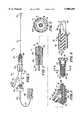
- FIG. 1is a side-elevational view of a low profile balloon-on-a-wire catheter incorporating the present invention.
- FIG. 2is an enlarged cross-sectional view of the proximal extremity of the catheter as shown in FIG. 1.
- FIG. 3is an enlarged cross-sectional view of an intermediate portion of the catheter shown in FIG. 1.
- FIG. 4is an enlarged sectional view of the distal extremity of the catheter shown in FIG. 1.
- FIG. 5is a cross-sectional view taken along the line of 5--5 of FIG. 4.
- FIG. 6is an enlarged sectional view of the distal extremity of a balloon-on-a-wire catheter incorporating another embodiment of the present invention.
- FIG. 7is a cross-sectional view taken along the line 7--7 of FIG. 6.
- FIG. 8is a side-elevational view partially in cross section of another embodiment of balloon-on-a-wire catheter incorporating the present invention making possible rapid inflation and deflation of the balloon and which has electrical functions.
- FIG. 9is a cross-sectional view taken along the line 9--9 of FIG. 8.
- FIG. 10is a cross-sectional view taken along the line 10--10 of FIG. 8.
- FIG. 11is a plan view of a kit including components for use with the catheter shown in FIG. 8.
- FIG. 12is a side-elevational view of the catheter shown in FIG. 8 with the accessories shown in the kit in FIG. 11 mounted on the proximal extremity of the balloon-on-a-wire catheter shown in FIG. 8.
- FIG. 13is a side-elevational view of a balloon-on-a-wire catheter incorporating another embodiment of the present invention which is of the mechanical type and does not include electrical functions.
- FIG. 14is a cross-sectional view taken along the line 14--14 of FIG. 13.
- FIG. 15is a plan view of a kit containing accessories for use with the catheter shown in FIG. 13.
- FIG. 16is a side-elevational view of the catheter shown in FIG. 13 with the accessories provided in the kit shown in FIG. 15 mounted on the proximal extremity thereof.
- the low profile balloon-on-a-wire catheteris comprised of a flexible elongate tubular member having proximal and distal extremities and having a lumen extending from the proximal extremity to the distal extremity.
- An inflatable balloonis carried by the distal extremity.
- Meansis carried by the flexible elongate tubular member for establishing communication between the lumen and the interior of the inflatable balloon.
- An inflation connectoris removably secured to the proximal extremity of the flexible elongate tubular member for supplying an inflation fluid to the lumen for inflating and deflating the balloon.
- the inflation connectorwhen removed provides a proximal extremity for the flexible elongate tubular member which is free of obstructions so that the flexible elongate tubular member can serve as a stand-alone guide wire for permitting advancement of another balloon angioplasty catheter over the flexible elongate tubular member.
- An electrical mechanismis provided in the distal extremity of the flexible elongate tubular member.
- Conductive meansis provided in the flexible elongate tubular member and is connected to the electrical mechanism and extends to the proximal extremity.
- Removable connector meansis coupled to the proximal extremity of the flexible elongate tubular member and makes electrical contact with the conductive means.
- the removable connector meanswhen removed from the flexible elongate tubular member provides a proximal extremity on the flexible elongate tubular member which is free of obstructions so that another angioplasty catheter can be advanced over the flexible elongate tubular member utilizing the flexible elongate tubular member as a stand alone guide wire.
- the low profile balloon-on-a-wire catheter 11consists of a flexible elongate tubular member 12 having proximal and distal extremities 13 and 14 and having a lumen 16 extending from the proximal extremity 13 to the distal extremity 14.
- the flexible elongate tubular member 12can be of a suitable material.
- itcan be formed of stainless steel having an outside diameter ranging from 0.010" to 0.032" but in accordance with the present invention preferably has a size ranging from 0.014" to 0.018" in outside diameter.
- Such a stainless steel hypotubecan have a wall thickness of 0.003" which for a 0.018" flexible elongate member would provide a lumen 16 of 0.012" in diameter.
- An insulating layer 17 formed of a suitable material such as a polyimideextends over the outer surface of the elongate tubular member 12.
- a mandrel or core wire 18is disposed within the lumen 16 of the flexible elongate tubular member 12 and can also be formed of a suitable material such as stainless steel or a superelastic shape memory alloy material.
- the core wire or mandrel 18can have a suitable diameter such as 0.008" so that there remains a coaxial or annular space which can serve as the lumen for inflating and deflating the balloon as hereinafter described.
- the core wire 18can extend from the proximal extremity to the distal extremity of the catheter 11.
- Typically such a mandrel or core wire 18would have centerless ground portions of reduced diameter to impart additional flexibility to the distal extremity of the catheter as described in the embodiment of the present invention shown in FIGS.
- the distal extremitycan be flattened to provide a ribbon-like configuration which is bonded into a solder bead or weld 21 in the form of a ball to provide a hemispherical frontal surface 22.
- This ball 21secures the mandrel or core wire 18 to the distal extremity of the flexible elongate tubular member 12.
- a layer of insulation 24 of a suitable materialsuch as a polyimide of a suitable thickness as for example 0.001" is provided.
- An elongate balloon 26 formed of a non-elastomeric materialis bonded to the distal extremity of the flexible elongate tubular member 12.
- the proximal and distal extremities 27 and 28 of the balloonare bonded to the distal extremity 14 of the flexible elongate tubular member 12 by suitable means such an adhesive so that a fluid-tight seal is formed between the proximal and distal extremities 27 and 28 and the flexible elongate member 12.
- the balloon 26typically would have an inflated diameter of 1.0 to 4.0 millimeters.
- Such a balloonwould have a wall thickness range of 0.0005" to 0.002" and would have a suitable length as for example 2 to 3 centimeters.
- Meansis provided for establishing communication between the lumen 16 of the flexible elongate tubular member 12 and the interior 29 of the balloon 26 and consists of a spiral slot 31 extending through the wall of the hypotube forming the flexible elongate tubular member 12 as shown in FIG. 4.
- the slot 31causes a helix 32 to be formed in the distal extremity of the hypotube 12.
- the helix 32serves to impart additional flexibility to the distal extremity of the flexible elongate tubular member 12 to facilitate steering and bending of the same.
- the helix 32can be formed as a separate part and then be bonded by suitable means such as welding to the flexible elongate tubular member 12.
- the helix 32can be formed in the distal extremity 14 of the flexible elongate tubular member 12.
- the other or proximal end of the lumen 16is sealed in a suitable manner, such as by an epoxy seal 36 (see FIG. 2) disposed about the insulated core wire 18.
- An electrical mechanism(not shown) of the type described in U.S. Pat. No. 5,238,005 and as shown in FIGS. 6 and 7 of another embodiment of the present invention utilizes a Nitinol element disposed within the helix 32 is provided for steering or bending the distal extremity 14 of the flexible elongate tubular member 12 as indicated by the dashed lines shown in FIG. 1.
- Conductive meansis provided for supplying electrical current to the electrical mechanism and in the present embodiment of the invention this conductive means is provided by the insulated core wire or mandrel 18 serving as one conductor and the hypotube 12 forming the flexible elongate tubular member 12 serving as the second conductor to provide conductive means which extends to the proximal extremity 13.
- the uninsulated portion of the core wire or mandrel 18serves to provide one cylindrical contact 41 and the uninsulated portion of the flexible elongate tubular member 12 in the form of the hypotube serves as the second cylindrical contact 42.
- These coaxial contacts 41 and 42are adapted to be engaged by a conventional removable connector 46 which is connected by cable 47 to a control console 48.
- the control consolesupplies electrical power to the electrical mechanism provided in the distal extremity for causing the desired bending of the distal extremity 14 of the flexible elongate member 12.
- the connector 46when removed from the proximal extremity of the flexible elongate tubular member 12 provides a proximal extremity for the flexible elongate tubular member which is free of obstructions so that another catheter can be advanced over the flexible elongate tubular member 12 permitting the flexible elongate tubular member 12 forming the catheter to be utilized as a stand alone guide wire as hereinafter described.
- Removable inflation means 51is secured to the proximal extremity of the flexible elongate member 12 and consists of a conventional Touhy-Borst wye-connector adapter 52.
- This adapter 52consists of a tubular member 53 formed of suitable material such as a clear plastic which is provided with a flow passage 54 therein through which the flexible elongate tubular member 12 can extend as shown particularly in FIGS. 1 and 3.
- a hemostasis valve assembly 56 and a Touhy-Borst adapter 57 having respectively seals 58 and 59 thereonare provided on opposite ends of the tubular member 53 and are adapted to be moved into frictional engagement with the flexible elongate element 12 to establish fluid-tight high pressure seals therewith.
- a rotating Luer connection having a rotatable sleeve 60interconnects the wye connector 52 and the Touhy-Borst adapter 57 and can be used as a means for applying torque. It is adapted to be engaged by the fingers of the hand for rotating the distal extremity of the catheter and/or guide wire 12.
- the proximal seal assembly 56is loosened slightly to permit rotation of the flexible elongate tubular member within the seal 58 while retaining a fluid-tight seal therewith.
- the tubular member 53is provided with a leg 61 which branches off at an angle from the flow passage 54. It is provided with a flow passage 62 in communication with the flow passage 54 and in communication with the conventional Luer fitting 63 which is adapted to receive an inflation device (not shown) that can be utilized for introducing an inflation fluid in the form of a radiopaque dye or a saline solution into the passage 62 and into the passage 54 so that the inflating fluid can be introduced into the lumen 16 of the flexible elongate member 12.
- Meansis provided for establishing communication between the passage 54 and the lumen 16 of the flexible elongate tubular member and consists of one or more elongate slots 66 formed in the sidewall of the hypotube forming the flexible elongate tubular member 12.
- the inflation means 51can be readily removed from the proximal extremity of the flexible elongate tubular member 12 by releasing the seals 58 and 59 from the flexible elongate tubular member 12 and then slipping the hemostatis valve 56, the wye-connector 52 and the Touhy-Borst adapter 57 off of the proximal extremity of the flexible elongate tubular member 12 to provide a proximal extremity on the flexible elongate tubular member 12 which is free of obstructions so that another angioplasty catheter can be advanced over the flexible elongate tubular member utilizing the flexible elongate tubular member as a stand alone guide wire.
- the core wire or mandrelif desired can be provided of a reduced length as for an example extending only approximately 30 centimeters from the distal extremity of the catheter 11 typically having a length of 150 to 180 centimeters.
- the conductive meanswould take the form of at least one additional wire and possibly two additional wires connected to the electrical mechanism in the distal extremity of the flexible elongate tubular member 12 and extending to the proximal extremity where they can be secured to conductive slip rings (not shown) to form the electrical connection with the connector 46.
- a guiding catheter(not shown) is introduced into the femoral artery in a conventional manner after which the low profile balloon-on-a-wire catheter 11 incorporating the present invention is introduced into the guiding catheter and then into the vessel by steering the same by use of the hereinbefore described electrical mechanism and/or with the use of the rotatable sleeve 60 through any tortuosities which may be encountered in the vessel until the selected stenosis is reached.
- the progress of the distal extremity of the low profile balloon-on-a-wire cathetercan be observed fluoroscopically in a manner well known to those skilled in the art.
- the catheter 11is then advanced through the selected stenosis until the balloon 26 is in registration with the selected stenosis.
- the balloon 26can be inflated by supplying an inflation fluid as for example by an inflation device to the adapter 51 so that the fluid will pass to the lumen 16 of the flexible elongate member 12 and then in to the interior 29 of the balloon 26.
- the balloon 26can be inflated and deflated one or more times as desired by the physician to create an opening in the selected stenosis which is at least large enough to permit some blood to flow through the selected stenosis.
- the catheter 11 which remains in placehas a distal extremity with an outside diameter approximately that of the main body of the catheter.
- the balloon 26 when deflatedwould only have a nominal wall thickness of 0.0003"-0.0005" so that when the balloon 26 is deflated the distal extremity of the catheter has an overall diameter which is approximately equal to or less than the diameter of the catheter 11 as for example 0.018".
- a conventional balloon cathetercan then be introduced over the catheter 11 utilizing the catheter 11 as a stand-alone guide wire to guide the larger size balloon angioplasty catheter into the selected stenosis.
- the catheter 11 of the present inventioncan be left in a position with the deflated balloon 26 thereon in registration with the selected stenosis.
- the other balloon of the conventional angioplasty catheterthen can be moved over the deflated balloon 26.
- the catheter 11 with the deflated balloon 26 thereoncan be advanced distally beyond the selected stenosis.
- the conventional balloon cathetercan then be advanced over the catheter 11 until its balloon is in registration with the selected stenosis.
- the balloon carried by the conventional balloon cathetercan then be inflated and deflated one or more times as desired by the physician to additionally dilate the selected stenosis to thereby create increased blood flow through the selected stenosis.
- the conventional angioplasty cathetercan be removed leaving the catheter and/or guide wire 11 or catheter/guide wire of the present invention still in place and then advancing a still larger size conventional balloon catheter over the catheter 11 and utilizing the same inflation and deflation procedure until the desired dilation of the stenosis has been obtained.
- the larger size balloon cathetercan then be removed along with the catheter/guide wire 11 of the present invention.
- the catheter or guide wire 11 of the present inventioncan be left in place and thereafter advanced or positioned so that the balloon 26 is in registration with the another selected stenosis.
- the inflation adapter 51is then remounted on the proximal extremity of the flexible elongate tubular member 12 and the seals 56 and 57 fastened.
- the balloon 26can then be inflated to enlarge the flow passage through the another selected stenosis in the same manner as for the selected stenosis.
- the inflation adapter 51can then be removed to permit other balloon catheters to be advanced over the free-of-obstructions proximal end of the catheter 11 in the manner hereinbefore described to provide the desired flow passage through the another selected stenosis.
- the same procedurecan be used in another selected stenosis which may be present in other branches of the arterial vessel of the patient. After all of the stenoses have been treated, the catheter 11 can be removed and the entry site can be closed.
- the balloon-on-a-wire catheter 71 shown thereinconsists of a flexible elongate tubular member 72 which has a proximal extremity (not shown) and a distal extremity 73.
- the flexible elongate tubular member 72can be formed of a suitable material such as a stainless steel hypotube having an outside diameter of 0.018" and having a wall thickness of 0.002" to provide a balloon inflation lumen 76 extending from the proximal extremity (not shown) to the distal extremity 73.
- a core wire or mandrel 78is disposed within the lumen 76 and is formed of a suitable material such as stainless steel.
- the distal extremity of the core wire or mandrel 78is provided with a portion 79 of reduced or smaller diameter as for example 0.004", another portion 80 of a still smaller diameter as for example 0.003", or portion 81 of a diameter of 0.002" and a flattened rectangular ribbon-like portion 82.
- the core wire 78is coated with an insulating coating 86 of a suitable material such as a polyimide to a thickness of approximately 0.0005".
- the distal extremity of the flexible elongate tubular member 72is ground down to form an annular recess at 87.
- a sleeve or elongate tubular member 91is provided which extends for a distance of 25-27 cm from the distal extremity of the hypotube 72 and is formed of a suitable material such as a polyimide. It has an outside diameter as for example of 0.018" and a wall thickness of 0.0015" to 0.004" and preferably an insulating layer 93 formed of a polyimide coating covers the entire length of the hypotube or flexible elongate member 72.
- a balloon 96 formed of a typical non-elastomeric material such as polyethylene or PEThas its proximal extremity 97 bonded to the exterior of the sleeve 91 by suitable means such as a heat seal.
- the distal extremity 98 of the balloon 96is also bonded to the proximal end of a coil 101 by suitable means such as a heat fuse or seal.
- the spring 101is formed of a radiopaque suitable material such as a platinum tungsten alloy. Its proximal extremity is sealed to the core mandrel by suitable means such as an adhesive 102.
- the distal extremity of the coil spring 101is secured to the core wire or mandrel 78 by a TEG weld forming a ball 103 providing a hemispheric forwardly or distally facing surface 104.
- the adhesive 102bonds the coil 101 to core wire or mandrel 78 and a polymer 105 such as silicone fills the space between the adhesive 102 and the ball 103.
- the siliconealso encapsulates the ball 103, which is first encapsulated by a uv-curable adhesive.
- a radiopaque marker 106 formed of a suitable material such as gold or platinumis disposed within the interior of the balloon 96 equidistant from the ends thereof on the exterior surface of the insulating coating 86 on the core mandrel 78.
- Suitable steering means of the type disclosed in U.S. Pat. No. 5,238,005is provided to permit steering of the distal extremity of the catheter or guide wire 71 as shown by dotted lines in FIG. 6 of the coil spring 101.
- This steering meansconsists of a Nitinol actuator wire or ribbon 111 having one end embedded in the ball 103 and having the other end secured to the distal extremity of the flexible elongate tubular member 72 by suitable means such as by bending said other end to extend through a pair of retaining slots 116 in the flexible elongate tubular member 72 and being retained therein by the sleeve 91 as shown in FIG. 6.
- the conductive means for supplying electrical energy to the steering means in the form of the Nitinol wire 111is provided by the insulated stainless steel core wire or mandrel 78 serving as one of the insulated conductors and the hypotube forming the flexible elongate tubular member 72 serving as the other conductor.
- first and second insulated conductive wirescan be provided within the balloon inflation lumen 76 to provide such conductive means.
- the proximal extremity of the catheter and/or guide wire 71 shown in FIGS. 6 and 7is constructed in a manner very similar to that shown in the previous embodiment and therefore will not be described in detail.
- a low profile balloon-on-a-wire catheterwhich can be converted from a catheter to a guide wire so that additional conventional balloon catheters can be introduced over the balloon-on-a-wire catheter utilizing the catheter as a stand-alone guide wire.
- the conversion from a catheter to a guide wirecan be readily accomplished merely by removing the attachments provided on the proximal extremity of the catheter, namely the attachment for inflating and deflating the balloon and the connector for making electrical connections to the electrical steering means.
- the catheter or guide wireis one which when converted can be utilized with rapid exchange catheters.
- a balloon-on-a-wire catheter construction of the type as shown in FIGS. 8, 9 and 10can be utilized.
- the balloon-on-a-wire catheter 151 incorporating the present invention as shown in FIG. 8consists of a flexible elongate tubular member 152 having proximal and distal extremities 153 and 154.
- the flexible elongate tubular member 152can be formed of a suitable material such as stainless steel.
- the flexible elongate tubular member 152which also can be called a hypo tube, can have a preferred inside diameter as for example 0.010" and an outside diameter of 0.017" to provide a wall thickness of 0.0035". It can have a suitable length, as for example 150-170 centimeters, which is conventional for angioplasty catheters.
- a balloon inflation lumen 156is provided which has a diameter of 0.010" to 0.0125".
- the distal extremity 154is provided with a taper 157 which adjoins a centerless ground portion 152a that is provided with a plurality of longitudinally extending spaced-apart slots 161.
- a core mandrel 166is provided having a proximal extremity 167 of a suitable diameter such as 0.004" that is threaded into and locked into the spaced-apart slots 161.
- the core mandrel 166is provided with a distal extremity 168 and with a portion 166a that is tapered and adjoins a portion 166b having a smaller diameter and a flattened portion 166c adjoining portion 166b.
- the core mandrel 166can have a suitable length as for example 30 centimeters and can have a suitable diameter as for example 0.005"-0.012".
- the core mandrel 166can be formed of a suitable material such as stainless steel or a nickel titanium alloy.
- An outer sleeve 171 formed of a suitable insulating material such as a polyimide having an outside diameter of 0.018" and an inside diameter of 0.0165"is secured to the portion 152a by suitable means such as an adhesive. Its distal extremity is provided with an annular recess 172 having one end of a balloon 176 typically formed of a non-elastomeric material such as PET secured in the annular recess 172 by suitable means such as a heat fuse or seal. The other end of the balloon 176 is bonded to the coil spring 181 typically formed of a suitable radiopaque material such as platinum, or a platinum tungsten alloy by suitable means such as a heat fuse or seal.
- a suitable radiopaque materialsuch as platinum, or a platinum tungsten alloy
- the coil 181is encapsulated in a suitable material such as a silicone 182 to provide an air-tight seal for the balloon 176 and to inhibit heat loss.
- a suitable materialsuch as a silicone 182 to provide an air-tight seal for the balloon 176 and to inhibit heat loss.
- an adhesive 183is placed in the coil 181 adjacent the distal extremity of the balloon 176 and forms an air-tight and fluid-tight seal with respect to the distal extremity of the balloon.
- a TEG or plasma weld 186is provided on the distal extremity of the coil spring 181 and is bonded to the distal extremity of the core mandrel 166 as shown in FIG. 8 to form one electrical connection for supplying energy to an actuator member 188 having one end connected into the TEG weld 186.
- the actuator member 188is formed of a suitable material such as a nickel titanium alloy having a negative coefficient of expansion. It is insulated so that it does not make contact with the conductive core mandrel 166.
- the actuator member 188extends proximally and makes contact with and is connected to a conductive coating 191 formed of a suitable material such as silver.
- the conductive coating 191is carried by an insulating layer 192 formed of a suitable material such as a polyimide which overlies the exterior of the hypotube 152.
- a marker band 196is provided on the core mandrel 166 and extends over the actuator member 188 and is formed of a suitable radiopaque material. The band 196 is disposed equidistant between the ends of the balloon 176 and is used to visualize the deployment of the balloon 176 during use.
- the conductive coating 191extends to the proximal extremity 153 and is covered with an insulating coating 198 having lubricous characteristics.
- the coating 198stops short of the proximal extremity of the conductive coating 191 carried by the insulating layer 192 so that it is exposed at 191a for making electrical contact therewith in the manner hereinbefore described.
- the proximal extremity of the hypotube 152is provided with a plurality of longitudinally extending spaced-apart slots 199 disposed in the side wall.
- the slots 199can have a suitable size as for example they can be rectangular having a length ranging from 0.029" to 0.031" and having a width of 0.01" and can be spaced apart by suitable distance as for example 0.1".
- the slots 199are utilized for providing inflation ports giving access to the bore or central lumen 156 for inflating and deflating the balloon 176.
- first and second electrical connections for supplying energy to the actuator member 188are also accessible from the proximal extremity with the first electrical connection being provided by the exposed portion 152b of the flexible elongate tubular member or hypotube 152 and the second electrical connection by the exposed portion 191a of the conductive layer 191.
- the catheter 151 shown in FIG. 8can be supplied in this form to the prospective user without any proximal attachments, which can be supplied in a kit 201 of the type shown in FIG. 11.
- the kit 201includes a torquer 202 of a conventional type which is provided with a collet 203. Rather than being formed of brass as in a conventional torquer, the collet 203 is formed of plastic so that it will not damage the outer coating 198 when the catheter 151 shown in FIG. 8 is disposed within the torquer 202.
- a splittable introducer 206 of a conventional typewhich typically is in the form of plastic and which is provided with a working length 207 which has a bent-over proximal extremity 208 which can serve as a handle. It can have a suitable length, as for example 10-15 centimeters and is provided with an inlet opening 209 leading to a passage (not shown) extending through the introducer through which the catheter 151 can be introduced.
- the introducer 206is adapted to be used to facilitate introducing the catheter 151 of the present invention into a guiding catheter conventionally used in angioplasty procedures in a manner well known to those skilled in the art.
- the kit 201also includes a Touhy-Borst adapter 211 which is removably mounted on the distal extremity of a Y-adapter 212 also of a conventional type.
- the Touhy-Borst adapter 211is provided with a threaded cap 223 which engages a sealing member 224 that forms a high-pressure seal.
- the Y-adapter 212is provided with a main or central arm 213 which carries a rotatable threaded cap 214 adapted to compress a sealing member 216 carried by the central arm 213 to form a high-pressure seal with respect to the catheter 151.
- the Y-adapter 212is also provided with a side arm 221 carrying a Luer-type fitting 222 that is adapted to be connected to an inflation device (not shown) of a conventional type which can be connected to the side arm 221 for inflating and deflating the balloon 176.
- the attachments or accessories 202, 206, 211 and 212are relatively inexpensive and can be readily packaged into the kit by mounting them on a cardboard 226 and covering them with plastic shrink wrap 227 in a conventional manner.
- the catheter 151is prepared by taking the catheter which has been packaged in an appropriate manner and separating it from the package and then taking the kit 201 and opening the same.
- the torquer 202is first taken and advanced over the proximal extremity of the catheter 151 so that it is distal of the slots 199.
- the collar 204is then rotated to engage the collet 203 to cause the collet 203 to firmly grasp the surface of the catheter 151 so that the catheter 151 can be rotated by use of the torquer 202.
- the Touhy-Borst adapter 211which is removably attached to the Y-adapter 212 is advanced over the proximal extremity 153 of the catheter 151 so that the Touhy-Borst adapter 211 is proximal of the torquer 202 and is distal of the slots 199 but with the threaded cap 214 of Y-adapter 212 being proximal of the slots 199.
- the threaded cap 223 on the Touhy-Borst adapter 211can then be adjusted to engage the sealing member 224 to compress the same to form a high-pressure seal between the Touhy-Borst adapter 211 and the catheter 151. Thereafter, the threaded cap 214 on the Y-adapter 212 can be rotated to also compress the seal 216 to form a high-pressure seal between the Y-adapter 212 and the catheter 151.
- high pressure sealsare provided on opposite sides of the slots 199.
- a guiding catheter(not shown) is introduced into a femoral artery of the patient in a conventional manner.
- the introducer 206then can be placed in the guiding catheter.
- the distal extremity of the catheter 151is then advanced into the opening 209 of the introducer 206 which guides the catheter 151 into the guiding catheter after which it can be advanced through the guiding catheter and into the desired vessel.
- the physicianobserves advancement of the same by fluoroscopy, observing the advancement of the marker 196 and coil 181.
- the torquer 202is utilized to facilitate maneuvering in tortuous vessels.
- the distal extremitycan be bent in a desired direction by use of a control console of the type hereinbefore described for causing a bend to be placed into the distal extremity of the catheter by supplying electrical energy to the actuator member 188 in a manner hereinbefore described.
- an inflation device(not shown) of a conventional type is attached to the side arm 221 and the balloon is rapidly inflated to its maximum size to a pressure of at least 10 atmospheres and preferably at least 15-20 atmospheres. This inflation can occur very rapidly even though the catheter 151 is of a very small size because the large lumen 156 which is provided opens into the large flow passage 173 provided in the outer sleeve 171 and is in direct communication with the interior of the balloon 176.
- Such a large inflation lumen 156is made possible because with the construction herein disclosed, it is unnecessary for the core wire or mandrel 166 to extend through the flexible elongate tubular member or hypotube 152 to the proximal extremity thereby providing a large inflation lumen extending from the proximal extremity 153 of the catheter to the flow passage 173 provided in the outer sleeve 171.
- the core mandrel 166is only present in the distalmost extremity of the catheter 151.
- the balloon 176can also be deflated in a very short period of time, as for example six seconds. These rapid inflation/deflation times have been provided without compromising the capabilities of the catheter 151.
- the distal extremitycan be shaped and deflected in the manner hereinbefore described. It also has the torquability and feel that is substantially equivalent to that of a High-Torque Floppy manufactured by Advanced Cardiovascular Systems, Inc. The desired torquability is retained by the use of the flexible elongate tubular member or hypotube 152 having increased wall thickness and being formed of superelastic material.
- FIGS. 13 and 14Another embodiment of a low profile angioplasty balloon-on-a-wire catheter with shapable and/or deflectable tip is shown in FIGS. 13 and 14 and is of the mechanical type and does not include the electrical functions provided by the catheter 151 shown in FIGS. 8-10.
- the catheter 251 shown in FIGS. 13 and 14consists of a flexible elongate member 152 of the type hereinbefore described in connection with the embodiment shown in FIGS. 8-10.
- an outer sleeve 171there is provided an outer sleeve 171.
- a balloon 176is carried thereby with a core mandrel 166 extending from the distal extremity of the flexible elongate tubular member 152 and is secured to the TEG weld 186.
- the principal difference between the two embodiments of the invention shown in FIGS. 8-10 and that shown in FIGS. 13-14is that the need for providing electrical conductors for supplying energy to an actuator member has been eliminated since the actuator member has been eliminated. Thus, the need for insulating coatings has been eliminated.
- the catheter 251 shown in FIG. 13can be supplied to the customer without any fittings or attachments being provided on the proximal extremity.
- the necessary fittings or accessoriescan be supplied in a kit 256 which in many respects is similar to the kit 201.
- torquer 202it is provided with a torquer 202, a splittable introducer 206 and a Touhy-Borst adapter 211 of the type hereinbefore described with the exception that the torquer 202 rather than being provided with a plastic collet is provided with a conventional metal collet since the collet is to engage the metal surface of the flexible elongate tubular member 152.
- attachments or accessors 202, 206 and 211can be packaged in the same manner as the kit 201.
- the catheter 251can be prepared by opening the kit 256 and placing the torquer 202 over the proximal extremity and tightening it on the catheter distal of the proximal extremity 153.
- the Touhy-Borst adapter 211can be mounted on the proximal most portion of the proximal extremity 153 since the balloon inflation lumen 156 opens through the proximal extremity 153.
- the Touhy-Borst adapteris then adjusted to provide a high-pressure seal between the Touhy-Borst adapter and the proximal extremity 153 of the catheter 251.
- a conventional inflation devicecan then be secured directly to the Touhy-Borst adapter 211.
- the distal extremity of the catheter 251can then be shaped if desired by the physician by utilizing the fingers of the hand to bend the distal extremity of the catheter 251, in particular the core mandrel 166 in a manner well known to those skilled in the art in utilizing angioplasty guide wires to place a predetermined bend in the distal extremity on the balloon-on-a-wire catheter 251.
- the balloon inflation-deflation lumen in the flexible elongate tubular memberis free of obstructions and is the only lumen in the flexible elongate tubular member and includes substantially the entire cross-sectional area within the flexible elongate tubular member.
- the Touhy-Borst adapter 211 and the torquer 202can be removed from the proximal extremity.
- the splittable introducer 206can be removed by grasping the bent-over portion 208 with the hand and pulling it sidewise to split off the catheter shaft provided by the flexible elongate tubular member 152.
- a conventional balloon catheter having a larger balloonthen can be advanced over the catheter 251 utilizing the catheter 251 as stand-alone guide wire for the larger size balloon angioplasty catheter.
- the other balloon cathetercan be advanced over the balloon-on-a-wire catheter using it as a stand-alone guide wire until its balloon is positioned within the stenosis after which that balloon can be inflated by a conventional inflation-deflation device.
- the conventional balloon cathetercan be advanced over the deflated balloon of the balloon-on-a-wire catheter while the balloon of the balloon-on-a-wire catheter is still in place in the stenosis.
- the deflated balloon of the balloon-on-a-wire cathetercan be advanced so that it is distal of the stenosis after which the balloon of the conventional balloon catheter can be advanced into the stenosis and inflated.
- the balloon catheter being utilizedcan be removed over the balloon-on-a-wire catheter 251 and another conventional balloon catheter inserted over the proximal extremity and advanced into the stenosis and inflated and deflated until the appropriate size flow passage or passageway has been formed in the stenosis. Thereafter, the conventional balloon catheter along with the balloon-on-a-wire catheter 251 can be removed in unison or separately if desired.
- the balloon-on-a-wire catheter of the present inventioncan be utilized because of its small diameter to form an initial passageway in the stenosis and can be left in place and additional balloon catheters of various sizes can be advanced over the same utilizing it as a stand-alone guide wire to advance the balloon carried thereby into registration with the stenosis and performing the appropriate inflation and deflation of the balloon carried thereby.
- the balloon-on-a-wire catheter of the present inventionin addition to performing dilation of the stenosis as hereinbefore described, also serves as a stand-alone guide wire for advancement of other larger size conventional balloon catheters into the stenosis without removal of the balloon-on-a-wire catheter 251.
- the balloon-on-a-wire catheter 251is removed only once during an angioplasty procedure.
- the use of the kit for the proximal attachment parts for the balloon-on-a-wire cathetergreatly reduces the cost of the balloon-on-a-wire catheter and makes it possible to readily attach and detach the necessary parts to the proximal extremities of the balloon-on-a-wire catheters.
- the balloon-on-a-wire catheter 151 hereinbefore described having electrical characteristicscan be utilized in a similar manner as a stand-alone guide wire merely by removing the Y-adapter 212, the Touhy-Borst adapter 211, the torquer 202 and the splittable introducer 206.
- the balloon-on-a-wire catheter of the present inventioncan be supplied to a prospective user in which its proximal extremity is free of obstructions and has a lumen which is accessible at the proximal extremity.
- a kit along with one or more balloon catheters of a conventional type of various balloon sizescan be shipped at the same time to the prospective user.
- the kitincludes the necessary accessories for operating the balloon-on-a-wire catheter while still permitting the balloon-on-a-wire catheter to be utilized as a stand-alone guide wire for the other conventional balloon catheter as hereinbefore explained.
- the kitneed only contain those attachments or accessories which are necessary to complete the functions of the balloon-on-a-wire catheter.
- the kitcan include removable inflation means which for the mechanical type balloon-on-a-wire catheter need only provide one high pressure seal or with respect to the balloon-on-a-wire catheter having electrical functions having inflation means capable of providing first and second high pressure seals disposed on opposite ends of the side opening in communication with the inflation-deflation lumen.
- the kitcan also include an introducer to facilitate introduction of the balloon-on-a-wire catheter into the guiding catheter conventionally used in angioplasty procedures. The cost of manufacture of the balloon-on-a-wire catheter of the present invention is reduced substantially with the attachments or accessories being supplied in a separate kit.
Landscapes
- Health & Medical Sciences (AREA)
- Life Sciences & Earth Sciences (AREA)
- Heart & Thoracic Surgery (AREA)
- Hematology (AREA)
- Engineering & Computer Science (AREA)
- Anesthesiology (AREA)
- Biomedical Technology (AREA)
- Pulmonology (AREA)
- Biophysics (AREA)
- Animal Behavior & Ethology (AREA)
- General Health & Medical Sciences (AREA)
- Public Health (AREA)
- Veterinary Medicine (AREA)
- Vascular Medicine (AREA)
- Child & Adolescent Psychology (AREA)
- Media Introduction/Drainage Providing Device (AREA)
Abstract
Description
Claims (8)
Priority Applications (1)
| Application Number | Priority Date | Filing Date | Title |
|---|---|---|---|
| US08/876,999US5908405A (en) | 1994-10-28 | 1997-06-16 | Low profile balloon-on-a-wire catheter with shapeable and/or deflectable tip and method |
Applications Claiming Priority (3)
| Application Number | Priority Date | Filing Date | Title |
|---|---|---|---|
| US08/331,217US5520645A (en) | 1994-10-28 | 1994-10-28 | Low profile angioplasty catheter and/or guide wire and method |
| US08/504,927US5779688A (en) | 1994-10-28 | 1995-07-20 | Low profile balloon-on-a-wire catheter with shapeable and/or deflectable tip and method |
| US08/876,999US5908405A (en) | 1994-10-28 | 1997-06-16 | Low profile balloon-on-a-wire catheter with shapeable and/or deflectable tip and method |
Related Parent Applications (1)
| Application Number | Title | Priority Date | Filing Date |
|---|---|---|---|
| US08/504,927ContinuationUS5779688A (en) | 1994-10-28 | 1995-07-20 | Low profile balloon-on-a-wire catheter with shapeable and/or deflectable tip and method |
Publications (1)
| Publication Number | Publication Date |
|---|---|
| US5908405Atrue US5908405A (en) | 1999-06-01 |
Family
ID=26987644
Family Applications (2)
| Application Number | Title | Priority Date | Filing Date |
|---|---|---|---|
| US08/504,927Expired - Fee RelatedUS5779688A (en) | 1994-10-28 | 1995-07-20 | Low profile balloon-on-a-wire catheter with shapeable and/or deflectable tip and method |
| US08/876,999Expired - Fee RelatedUS5908405A (en) | 1994-10-28 | 1997-06-16 | Low profile balloon-on-a-wire catheter with shapeable and/or deflectable tip and method |
Family Applications Before (1)
| Application Number | Title | Priority Date | Filing Date |
|---|---|---|---|
| US08/504,927Expired - Fee RelatedUS5779688A (en) | 1994-10-28 | 1995-07-20 | Low profile balloon-on-a-wire catheter with shapeable and/or deflectable tip and method |
Country Status (5)
| Country | Link |
|---|---|
| US (2) | US5779688A (en) |
| EP (1) | EP0843570A4 (en) |
| JP (1) | JPH10507949A (en) |
| AU (1) | AU692949B2 (en) |
| WO (1) | WO1996013297A1 (en) |
Cited By (103)
| Publication number | Priority date | Publication date | Assignee | Title |
|---|---|---|---|---|
| US6102890A (en)* | 1998-10-23 | 2000-08-15 | Scimed Life Systems, Inc. | Catheter having improved proximal shaft design |
| US6260890B1 (en)* | 1999-08-12 | 2001-07-17 | Breg, Inc. | Tubing connector |
| US6325777B1 (en) | 1996-05-20 | 2001-12-04 | Medtronic Percusurge, Inc. | Low profile catheter valve and inflation adaptor |
| US6325778B1 (en) | 1996-05-20 | 2001-12-04 | Medtronic Percusurge, Inc. | Low profile catheter valve and inflation adaptor |
| US6332881B1 (en) | 1999-09-01 | 2001-12-25 | Cardima, Inc. | Surgical ablation tool |
| US6355014B1 (en) | 1996-05-20 | 2002-03-12 | Medtronic Percusurge, Inc. | Low profile catheter valve |
| US20020052638A1 (en)* | 1996-05-20 | 2002-05-02 | Gholam-Reza Zadno-Azizi | Method and apparatus for emboli containment |
| US20020065507A1 (en)* | 1996-05-20 | 2002-05-30 | Gholam-Reza Zadno-Azizi | Exchange method for emboli containment |
| US6423052B1 (en) | 2000-08-18 | 2002-07-23 | Endovascular Technologies, Inc. | Torque absorbing catheter |
| US20020165571A1 (en)* | 2000-08-21 | 2002-11-07 | Stephen Hebert | Manipulatable delivery catheter for occlusive devices (ll) |
| US6500147B2 (en) | 1999-02-22 | 2002-12-31 | Medtronic Percusurge, Inc. | Flexible catheter |
| US20030055483A1 (en)* | 2001-08-23 | 2003-03-20 | Gumm Darrell C. | Rotating stent delivery system for side branch access and protection and method of using same |
| US6544215B1 (en)* | 1998-10-02 | 2003-04-08 | Scimed Life Systems, Inc. | Steerable device for introducing diagnostic and therapeutic apparatus into the body |
| US20030088194A1 (en)* | 2001-11-06 | 2003-05-08 | Bonnette Michael J. | Gas Inflation/evacution system for guidewire having occlusive device |
| US20030088208A1 (en)* | 1999-12-02 | 2003-05-08 | Embol-X, Inc. | Buoyant tip aspiration catheter and methods of use |
| US20030181827A1 (en)* | 2002-03-22 | 2003-09-25 | Hikmat Hojeibane | Guidewire with deflectable tip |
| US6726700B1 (en) | 2000-08-21 | 2004-04-27 | Counter Clockwise, Inc. | Manipulatable delivery catheter for occlusive devices |
| US20040082881A1 (en)* | 2002-03-22 | 2004-04-29 | David Grewe | Guidewire with deflectable tip having improved torque characteristics |
| US20040153138A1 (en)* | 2002-03-25 | 2004-08-05 | Kieran Murphy | Device viewable under an imaging beam |
| US20040172119A1 (en)* | 2003-02-27 | 2004-09-02 | Scimed Life Systems, Inc. | Rotating balloon expandable sheath bifurcation delivery |
| US20040172121A1 (en)* | 2003-02-27 | 2004-09-02 | Tracee Eidenschink | Rotating balloon expandable sheath bifurcation delivery |
| US6786888B1 (en) | 1996-05-20 | 2004-09-07 | Medtronic Ave, Inc. | Low profile catheter for emboli protection |
| US20040176682A1 (en)* | 2003-03-03 | 2004-09-09 | Murphy Kieran P. | Method and apparatus for reducing exposure to an imaging beam |
| US20040193205A1 (en)* | 2002-03-22 | 2004-09-30 | Robert Burgermeister | Steerable balloon catheter |
| US20050038494A1 (en)* | 2003-08-15 | 2005-02-17 | Scimed Life Systems, Inc. | Clutch driven stent delivery system |
| US20050055077A1 (en)* | 2003-09-05 | 2005-03-10 | Doron Marco | Very low profile medical device system having an adjustable balloon |
| US20050149161A1 (en)* | 2003-12-29 | 2005-07-07 | Tracee Eidenschink | Edge protection and bifurcated stent delivery system |
| US20050182473A1 (en)* | 2004-02-18 | 2005-08-18 | Tracee Eidenschink | Multi stent delivery system |
| US6932828B2 (en) | 2001-11-06 | 2005-08-23 | Possis Medical, Inc. | Guidewire occlusion system utilizing repeatably inflatable gas-filled occlusive device |
| US20050183259A1 (en)* | 2004-02-23 | 2005-08-25 | Tracee Eidenschink | Apparatus and method for crimping a stent assembly |
| US20050209674A1 (en)* | 2003-09-05 | 2005-09-22 | Kutscher Tuvia D | Balloon assembly (V) |
| US20050234425A1 (en)* | 2004-04-16 | 2005-10-20 | Innospine, Inc. | Spinal diagnostic methods and apparatus |
| US20050273149A1 (en)* | 2004-06-08 | 2005-12-08 | Tran Thomas T | Bifurcated stent delivery system |
| US20060064071A1 (en)* | 2001-11-06 | 2006-03-23 | Possis Medical, Inc. | Gas inflation/evacuation system incorporating a reservoir and removably attached sealing system for a guidewire assembly having an occlusive device |
| US20060190005A1 (en)* | 2004-12-29 | 2006-08-24 | Cook Incorporated | Introducer tactile feature |
| US7169161B2 (en) | 2001-11-06 | 2007-01-30 | Possis Medical, Inc. | Guidewire having occlusive device and repeatably crimpable proximal end |
| US20070060881A1 (en)* | 2005-09-01 | 2007-03-15 | Posis Medical, Inc. | Gas inflation/evacuation system incorporating a multiple element valved guidewire assembly having an occlusive device |
| US20070213689A1 (en)* | 2002-03-22 | 2007-09-13 | Grewe David D | Deflectable tip infusion guidewire |
| US20070219465A1 (en)* | 2002-03-22 | 2007-09-20 | Rudolph Cedro | Guidewire with deflectable tip having improved flexibility |
| US20070219464A1 (en)* | 2002-03-22 | 2007-09-20 | Stephen Davis | Guidewire with deflectable re-entry tip |
| US20080097294A1 (en)* | 2006-02-21 | 2008-04-24 | Possis Medical, Inc. | Occlusive guidewire system having an ergonomic handheld control mechanism prepackaged in a pressurized gaseous environment and a compatible prepackaged torqueable kink-resistant guidewire with distal occlusive balloon |
| US20080188800A1 (en)* | 1998-10-02 | 2008-08-07 | Bencini Robert F | Steerable Device For Introducing Diagnostic And Therapeutic Apparatus Into The Body |
| US20080249465A1 (en)* | 2007-04-06 | 2008-10-09 | John Kenneth Ryder | Fixed wire dilatation catheter with an elongateable distal end |
| US20080306465A1 (en)* | 2007-06-05 | 2008-12-11 | Cook Incorporated | Adjustable Length Catheter |
| WO2009003113A1 (en)* | 2007-06-26 | 2008-12-31 | Unique Catheter Designs, Llc | Catheter apparatus and methods for treating vasculatures |
| US20090088730A1 (en)* | 2007-09-28 | 2009-04-02 | Codman & Shurtleff, Inc. | Catheter for reduced reflux in targeted tissue delivery of a therapeutic agent |
| US20090287289A1 (en)* | 2008-05-19 | 2009-11-19 | Mark Sagedahl | Bifurcation stent crimping systems and methods |
| US20100056958A1 (en)* | 2008-06-18 | 2010-03-04 | Kumar Lava Ravi | Device for measuring blockage length in a blood vessel |
| US7744619B2 (en) | 2004-02-24 | 2010-06-29 | Boston Scientific Scimed, Inc. | Rotatable catheter assembly |
| US7815600B2 (en) | 2002-03-22 | 2010-10-19 | Cordis Corporation | Rapid-exchange balloon catheter shaft and method |
| US7824390B2 (en) | 2004-04-16 | 2010-11-02 | Kyphon SÀRL | Spinal diagnostic methods and apparatus |
| US7922753B2 (en) | 2004-01-13 | 2011-04-12 | Boston Scientific Scimed, Inc. | Bifurcated stent delivery system |
| US7922740B2 (en) | 2004-02-24 | 2011-04-12 | Boston Scientific Scimed, Inc. | Rotatable catheter assembly |
| US8133199B2 (en) | 2008-08-27 | 2012-03-13 | Boston Scientific Scimed, Inc. | Electroactive polymer activation system for a medical device |
| US8157766B2 (en) | 2005-09-01 | 2012-04-17 | Medrad, Inc. | Torqueable kink-resistant guidewire |
| US20120209176A1 (en)* | 2011-02-09 | 2012-08-16 | Boston Scientific Scimed, Inc. | Balloon catheter |
| US20130030519A1 (en)* | 2011-07-27 | 2013-01-31 | Edwards Lifesciences Corporation | Delivery systems for prosthetic heart valve |
| US8608703B2 (en) | 2007-06-12 | 2013-12-17 | Medrad, Inc. | Infusion flow guidewire system |
| US9125683B2 (en) | 2007-06-26 | 2015-09-08 | Roxwood Medical Inc. | Method and apparatus for placing a catheter within a vasculature |
| US9126020B2 (en) | 2007-06-26 | 2015-09-08 | Roxwood Medical, Inc. | Catheter apparatus with telescoping lumen catheters and its use in methods for treating vasculatures |
| US9238119B2 (en) | 2010-08-12 | 2016-01-19 | Boston Scientific Limited | Infusion flow system and fluid coupling |
| US9358037B2 (en) | 2007-06-26 | 2016-06-07 | Roxwood Medical, Inc. | Method and apparatus for centering a microcatheter within a vasculature |
| US9375203B2 (en) | 2002-03-25 | 2016-06-28 | Kieran Murphy Llc | Biopsy needle |
| US9427254B2 (en) | 2002-03-25 | 2016-08-30 | Kieran Murphy Llc | Apparatus for use in a surgical procedure |
| EP3033135B1 (en) | 2013-08-14 | 2017-05-24 | Boston Scientific Scimed, Inc. | Medical guidewire |
| US9943668B2 (en) | 2010-07-16 | 2018-04-17 | Sub3 Vascular, Llc | Guidewire and catheter system and method for treating a blood clot |
| US10321996B2 (en) | 2015-11-11 | 2019-06-18 | Edwards Lifesciences Corporation | Prosthetic valve delivery apparatus having clutch mechanism |
| US10426510B2 (en) | 2012-10-22 | 2019-10-01 | Roxwood Medical, Inc. | Method and apparatus for centering a microcatheter within a vasculature |
| US10441419B2 (en) | 2008-05-09 | 2019-10-15 | Edwards Lifesciences Corporation | Low profile delivery system for transcatheter heart valve |
| US10478294B2 (en) | 2005-06-13 | 2019-11-19 | Edwards Lifesciences Corporation | Method for delivering a prosthetic heart valve |
| US10561494B2 (en) | 2011-02-25 | 2020-02-18 | Edwards Lifesciences Corporation | Prosthetic heart valve delivery apparatus |
| US10596354B2 (en) | 2015-09-25 | 2020-03-24 | Mark Taber | Guide wires, catheters, and guide wire catheter systems and methods |
| US10646342B1 (en) | 2017-05-10 | 2020-05-12 | Edwards Lifesciences Corporation | Mitral valve spacer device |
| US10799676B2 (en) | 2016-03-21 | 2020-10-13 | Edwards Lifesciences Corporation | Multi-direction steerable handles for steering catheters |
| US10799677B2 (en) | 2016-03-21 | 2020-10-13 | Edwards Lifesciences Corporation | Multi-direction steerable handles for steering catheters |
| US10806575B2 (en) | 2008-08-22 | 2020-10-20 | Edwards Lifesciences Corporation | Heart valve treatment system |
| US10806573B2 (en) | 2017-08-22 | 2020-10-20 | Edwards Lifesciences Corporation | Gear drive mechanism for heart valve delivery apparatus |
| US10842627B2 (en) | 2017-04-18 | 2020-11-24 | Edwards Lifesciences Corporation | Heart valve sealing devices and delivery devices therefor |
| US10857334B2 (en) | 2017-07-12 | 2020-12-08 | Edwards Lifesciences Corporation | Reduced operation force inflator |
| US10874514B2 (en) | 2017-04-18 | 2020-12-29 | Edwards Lifesciences Corporation | Heart valve sealing devices and delivery devices therefor |
| US10973634B2 (en) | 2017-04-26 | 2021-04-13 | Edwards Lifesciences Corporation | Delivery apparatus for a prosthetic heart valve |
| US11051939B2 (en) | 2017-08-31 | 2021-07-06 | Edwards Lifesciences Corporation | Active introducer sheath system |
| US11207499B2 (en) | 2017-10-20 | 2021-12-28 | Edwards Lifesciences Corporation | Steerable catheter |
| US11219746B2 (en) | 2016-03-21 | 2022-01-11 | Edwards Lifesciences Corporation | Multi-direction steerable handles for steering catheters |
| US11234814B2 (en) | 2015-08-14 | 2022-02-01 | Edwards Lifesciences Corporation | Gripping and pushing device for medical instrument |
| US11259920B2 (en) | 2015-11-03 | 2022-03-01 | Edwards Lifesciences Corporation | Adapter for prosthesis delivery device and methods of use |
| US11291540B2 (en) | 2017-06-30 | 2022-04-05 | Edwards Lifesciences Corporation | Docking stations for transcatheter valves |
| US11311399B2 (en) | 2017-06-30 | 2022-04-26 | Edwards Lifesciences Corporation | Lock and release mechanisms for trans-catheter implantable devices |
| US11779728B2 (en) | 2018-11-01 | 2023-10-10 | Edwards Lifesciences Corporation | Introducer sheath with expandable introducer |
| US11806231B2 (en) | 2020-08-24 | 2023-11-07 | Edwards Lifesciences Corporation | Commissure marker for a prosthetic heart valve |
| US11844914B2 (en) | 2018-06-05 | 2023-12-19 | Edwards Lifesciences Corporation | Removable volume indicator for syringe |
| US11857416B2 (en) | 2017-10-18 | 2024-01-02 | Edwards Lifesciences Corporation | Catheter assembly |
| US11944559B2 (en) | 2020-08-31 | 2024-04-02 | Edwards Lifesciences Corporation | Systems and methods for crimping and device preparation |
| US12042617B2 (en) | 2018-02-13 | 2024-07-23 | Kieran P. Murphy | Delivery system for delivering a drug depot to a target site under image guidance and methods and uses of same |
| US12121672B2 (en) | 2018-04-30 | 2024-10-22 | Edwards Lifesciences Corporation | Advanced sheath patterns |
| US12208004B2 (en) | 2015-10-26 | 2025-01-28 | Edwards Lifesciences Corporation | Implant delivery capsule |
| US12263086B2 (en) | 2018-12-12 | 2025-04-01 | Edwards Lifesciences Corporation | Combined introducer and expandable sheath |
| US12268599B2 (en) | 2018-12-11 | 2025-04-08 | Edwards Lifesciences Corporation | Delivery systems for prosthetic heart valve |
| US12357456B2 (en) | 2018-04-30 | 2025-07-15 | Edwards Lifesciences Corporation | Devices and methods for crimping prosthetic implants |
| USD1084324S1 (en) | 2023-08-01 | 2025-07-15 | Edwards Lifesciences Corporation | Handle for implant delivery device |
| US12364600B2 (en) | 2015-09-16 | 2025-07-22 | Edwards Lifesciences Corporation | Perfusion balloon design |
| US12427019B2 (en) | 2019-01-16 | 2025-09-30 | Edwards Lifesciences Corporation | Apparatus and method for monitoring valve expansion |
| US12440334B2 (en) | 2021-09-17 | 2025-10-14 | Edwards Lifesciences Corporation | Delivery apparatus for a prosthetic valve |
Families Citing this family (71)
| Publication number | Priority date | Publication date | Assignee | Title |
|---|---|---|---|---|
| US6146355A (en)* | 1996-12-30 | 2000-11-14 | Myelotec, Inc. | Steerable catheter |
| US6213974B1 (en)* | 1996-12-30 | 2001-04-10 | Visionary Biomedical, Inc. | Steerable catheter having segmented tip and one-piece inlet housing, and method of fabricating same |
| US6156053A (en)* | 1998-05-01 | 2000-12-05 | Intella Interventional Systems, Inc. | Dual catheter assembly |
| EP1447057A1 (en) | 1998-09-30 | 2004-08-18 | Bard Peripheral Vascular, Inc. | Delivery mechanism for implantable stent |
| US6641573B1 (en) | 1999-03-25 | 2003-11-04 | Arteria Medical Science, Inc. | Device and method of guide wire balloon inflation and deflation to prevent cerebral embolization during carotid stenting |
| WO2001074260A1 (en)* | 2000-03-24 | 2001-10-11 | Johns Hopkins University | Peritoneal cavity device and method |
| US7344546B2 (en)* | 2000-04-05 | 2008-03-18 | Pathway Medical Technologies | Intralumenal material removal using a cutting device for differential cutting |
| US6616597B2 (en)* | 2000-12-12 | 2003-09-09 | Datascope Investment Corp. | Intra-aortic balloon catheter having a dual sensor pressure sensing system |
| EP1764124B1 (en)* | 2000-12-12 | 2011-01-19 | Datascope Investment Corp. | Intra-aortic balloon catheter having a fiberoptic sensor |
| US20020111645A1 (en)* | 2001-02-15 | 2002-08-15 | Scimed Life System, Inc. | Vacuum prep catheter |
| US6666828B2 (en)* | 2001-06-29 | 2003-12-23 | Medtronic, Inc. | Catheter system having disposable balloon |
| US20050182437A1 (en)* | 2001-11-06 | 2005-08-18 | Bonnette Michael J. | Guidewire assembly including a repeatably inflatable occlusive balloon on a guidewire ensheathed with a spiral coil |
| US20070167804A1 (en)* | 2002-09-18 | 2007-07-19 | Byong-Ho Park | Tubular compliant mechanisms for ultrasonic imaging systems and intravascular interventional devices |
| CA2499389A1 (en)* | 2002-09-18 | 2004-04-01 | The Board Of Trustees Of The Leland Stanford Junior University | Tubular compliant mechanisms for ultrasonic imaging systems and intravascular interventional devices |
| US7485139B1 (en)* | 2002-10-10 | 2009-02-03 | Ciamacco Jr Sam | Stent delivery and deployment system |
| US8092450B2 (en)* | 2003-01-21 | 2012-01-10 | Baylis Medical Company Inc. | Magnetically guidable energy delivery apparatus and method of using same |
| US8177760B2 (en) | 2004-05-12 | 2012-05-15 | C. R. Bard, Inc. | Valved connector |
| US20060130617A1 (en)* | 2004-12-20 | 2006-06-22 | Mamourian Alexander C | Catheter connector wrench |
| EP2461180A1 (en)* | 2005-05-04 | 2012-06-06 | Volcano Corporation | Miniature actuator mechanism for intravascular imaging |
| US12161390B2 (en) | 2006-09-29 | 2024-12-10 | Boston Scientific Medical Device Limited | Connector system for electrosurgical device |
| US11666377B2 (en) | 2006-09-29 | 2023-06-06 | Boston Scientific Medical Device Limited | Electrosurgical device |
| US9510885B2 (en) | 2007-11-16 | 2016-12-06 | Osseon Llc | Steerable and curvable cavity creation system |
| US8016851B2 (en)* | 2007-12-27 | 2011-09-13 | Cook Medical Technologies Llc | Delivery system and method of delivery for treating obesity |
| US20100298832A1 (en) | 2009-05-20 | 2010-11-25 | Osseon Therapeutics, Inc. | Steerable curvable vertebroplasty drill |
| US9125671B2 (en) | 2010-04-29 | 2015-09-08 | Dfine, Inc. | System for use in treatment of vertebral fractures |
| US10434292B2 (en) | 2011-06-24 | 2019-10-08 | Access Closure | Method and devices for flow occlusion during device exchanges |
| US9119639B2 (en) | 2011-08-09 | 2015-09-01 | DePuy Synthes Products, Inc. | Articulated cavity creator |
| EP2792322B1 (en)* | 2011-08-25 | 2017-10-04 | Covidien LP | Systems and devices for treatment of luminal tissue |
| US8632467B2 (en) | 2011-10-12 | 2014-01-21 | Volcano Corporation | Rotational shape-memory actuators and associated devices, systems, and methods |
| US9532785B2 (en) | 2012-05-09 | 2017-01-03 | Access Closure, Inc. | Method and devices for flow occlusion during device exchanges |
| EP4599879A2 (en) | 2012-05-31 | 2025-08-13 | Boston Scientific Medical Device Limited | Radiofrequency perforation apparatus |
| US9439693B2 (en) | 2013-02-01 | 2016-09-13 | DePuy Synthes Products, Inc. | Steerable needle assembly for use in vertebral body augmentation |
| US11937873B2 (en) | 2013-03-12 | 2024-03-26 | Boston Scientific Medical Device Limited | Electrosurgical device having a lumen |
| EP2968846B1 (en) | 2013-03-12 | 2022-05-04 | Baylis Medical Company Inc. | Medical device having a support structure |
| CA3220441A1 (en) | 2013-03-15 | 2015-09-17 | Boston Scientific Medical Device Limited | Electrosurgical device having a distal aperture |
| CN105682726B (en) | 2013-08-07 | 2020-01-03 | 贝利斯医疗公司 | Method and apparatus for puncturing tissue |
| US10661057B2 (en) | 2013-12-20 | 2020-05-26 | Baylis Medical Company Inc. | Steerable medical device handle |
| AU2016319002B2 (en) | 2015-09-09 | 2021-05-13 | Boston Scientific Medical Device Limited | Epicardial access system & methods |
| WO2017118948A1 (en) | 2016-01-07 | 2017-07-13 | Baylis Medical Company Inc. | Hybrid transseptal dilator and methods of using the same |
| JP2019534130A (en) | 2016-10-27 | 2019-11-28 | ディーファイン,インコーポレイティド | Articulated osteotome with cement delivery channel |
| CN110114027B (en) | 2016-11-01 | 2022-09-06 | 贝利斯医疗公司 | Method and apparatus for puncturing tissue |
| CA3041114A1 (en) | 2016-11-28 | 2018-05-31 | Dfine, Inc. | Tumor ablation devices and related methods |
| US10470781B2 (en) | 2016-12-09 | 2019-11-12 | Dfine, Inc. | Medical devices for treating hard tissues and related methods |
| US10660656B2 (en) | 2017-01-06 | 2020-05-26 | Dfine, Inc. | Osteotome with a distal portion for simultaneous advancement and articulation |
| BR112020011128A2 (en) | 2017-08-10 | 2021-05-04 | Baylis Medical Company Inc. | heat exchange device and temperature sensor and method of use |
| CA3082315A1 (en) | 2017-11-22 | 2019-05-31 | Front Line Medical Technologies Inc. | Devices and method for blood vessel occlusion |
| EP3579909B1 (en) | 2017-12-05 | 2020-09-09 | Pedersen, Wesley Robert | Transseptal guide wire puncture system |
| CN112272574A (en) | 2018-05-08 | 2021-01-26 | 贝利斯医疗公司 | Coupling mechanism for device |
| US11937864B2 (en) | 2018-11-08 | 2024-03-26 | Dfine, Inc. | Ablation systems with parameter-based modulation and related devices and methods |
| KR20220021468A (en) | 2019-04-29 | 2022-02-22 | 베이리스 메디컬 컴퍼니 아이엔씨. | Transseptal system, device and method |
| US11986229B2 (en) | 2019-09-18 | 2024-05-21 | Merit Medical Systems, Inc. | Osteotome with inflatable portion and multiwire articulation |
| US11759190B2 (en) | 2019-10-18 | 2023-09-19 | Boston Scientific Medical Device Limited | Lock for medical devices, and related systems and methods |
| US11801087B2 (en) | 2019-11-13 | 2023-10-31 | Boston Scientific Medical Device Limited | Apparatus and methods for puncturing tissue |
| US11724070B2 (en) | 2019-12-19 | 2023-08-15 | Boston Scientific Medical Device Limited | Methods for determining a position of a first medical device with respect to a second medical device, and related systems and medical devices |
| US11931098B2 (en) | 2020-02-19 | 2024-03-19 | Boston Scientific Medical Device Limited | System and method for carrying out a medical procedure |
| US12082792B2 (en) | 2020-02-25 | 2024-09-10 | Boston Scientific Medical Device Limited | Systems and methods for creating a puncture between aorta and the left atrium |
| US11986209B2 (en) | 2020-02-25 | 2024-05-21 | Boston Scientific Medical Device Limited | Methods and devices for creation of communication between aorta and left atrium |
| US11819243B2 (en) | 2020-03-19 | 2023-11-21 | Boston Scientific Medical Device Limited | Medical sheath and related systems and methods |
| US11826075B2 (en) | 2020-04-07 | 2023-11-28 | Boston Scientific Medical Device Limited | Elongated medical assembly |
| US12011279B2 (en) | 2020-04-07 | 2024-06-18 | Boston Scientific Medical Device Limited | Electro-anatomic mapping system |
| US12420067B2 (en) | 2020-05-12 | 2025-09-23 | Boston Scientific Medical Device Limited | Guidewire assembly |
| US11938285B2 (en) | 2020-06-17 | 2024-03-26 | Boston Scientific Medical Device Limited | Stop-movement device for elongated medical assembly |
| CN116437857A (en) | 2020-06-17 | 2023-07-14 | 波士顿科学医疗设备有限公司 | Electroanatomical mapping system |
| US11937796B2 (en) | 2020-06-18 | 2024-03-26 | Boston Scientific Medical Device Limited | Tissue-spreader assembly |
| US12343042B2 (en) | 2020-07-16 | 2025-07-01 | Boston Scientific Medical Device Limited | Pericardial puncture device and method |
| US11986199B2 (en)* | 2020-07-16 | 2024-05-21 | EndoGear, LLC | Grasping device for independent tissue manipulation during gastrointestinal endoscopic procedures and methods of use |
| US12042178B2 (en) | 2020-07-21 | 2024-07-23 | Boston Scientific Medical Device Limited | System of medical devices and method for pericardial puncture |
| US12005202B2 (en) | 2020-08-07 | 2024-06-11 | Boston Scientific Medical Device Limited | Catheter having tissue-engaging device |
| US12396785B2 (en) | 2020-08-12 | 2025-08-26 | Boston Scientific Medical Device Limited | System of medical devices and method for pericardial puncture |
| CA3128527A1 (en) | 2020-09-10 | 2022-03-10 | Baylis Medical Company Inc. | Elongated medical catheter including marker band |
| US11980412B2 (en) | 2020-09-15 | 2024-05-14 | Boston Scientific Medical Device Limited | Elongated medical sheath |
Citations (23)
| Publication number | Priority date | Publication date | Assignee | Title |
|---|---|---|---|---|
| US4664113A (en)* | 1984-05-30 | 1987-05-12 | Advanced Cardiovascular Systems, Inc. | Steerable dilatation catheter with rotation limiting device |
| US4715378A (en)* | 1986-07-28 | 1987-12-29 | Mansfield Scientific, Inc. | Balloon catheter |
| US4793305A (en)* | 1987-07-16 | 1988-12-27 | Dresser Industries, Inc. | High turbulence combustion chamber for turbocharged lean burn gaseous fueled engine |
| US4838269A (en)* | 1988-03-24 | 1989-06-13 | Scimed Life Systems, Inc. | Manifold for angioplasty balloon catheter |
| US4846174A (en)* | 1986-08-08 | 1989-07-11 | Scimed Life Systems, Inc. | Angioplasty dilating guide wire |
| US4848344A (en)* | 1987-11-13 | 1989-07-18 | Cook, Inc. | Balloon guide |
| US5035694A (en)* | 1989-05-15 | 1991-07-30 | Advanced Cardiovascular Systems, Inc. | Dilatation catheter assembly with heated balloon |
| US5045061A (en)* | 1990-02-02 | 1991-09-03 | C. R. Bard, Inc. | Balloon catheter and locking guidewire system |
| US5069226A (en)* | 1989-04-28 | 1991-12-03 | Tokin Corporation | Catheter guidewire with pseudo elastic shape memory alloy |
| US5242394A (en)* | 1985-07-30 | 1993-09-07 | Advanced Cardiovascular Systems, Inc. | Steerable dilatation catheter |
| US5255690A (en)* | 1992-07-16 | 1993-10-26 | Scimed Life Systems, Inc. | Method and apparatus for proximal support of a guide wire during catheter exchange |
| US5338301A (en)* | 1993-08-26 | 1994-08-16 | Cordis Corporation | Extendable balloon-on-a-wire catheter, system and treatment procedure |
| US5349964A (en)* | 1993-05-05 | 1994-09-27 | Intelliwire, Inc. | Device having an electrically actuatable section with a portion having a current shunt and method |
| US5364354A (en)* | 1991-04-24 | 1994-11-15 | Baxter International Inc. | Exchangeable integrated-wire balloon catheter |
| US5385562A (en)* | 1990-10-29 | 1995-01-31 | Scimed Life Systems, Inc. | Guide catheter system for an angioplasty balloon catheter |
| US5417658A (en)* | 1992-03-17 | 1995-05-23 | Scimed Life Systems, Inc. | Balloon dilatation catheter having a torsionally soft component |
| USRE35176E (en)* | 1985-07-30 | 1996-03-12 | Advanced Cardiovascular Systems, Inc. | Self-venting balloon dilatation catheter and method |
| US5505699A (en)* | 1994-03-24 | 1996-04-09 | Schneider (Usa) Inc. | Angioplasty device |
| US5520645A (en)* | 1994-10-28 | 1996-05-28 | Intelliwire, Inc. | Low profile angioplasty catheter and/or guide wire and method |
| US5527292A (en)* | 1990-10-29 | 1996-06-18 | Scimed Life Systems, Inc. | Intravascular device for coronary heart treatment |
| US5549554A (en)* | 1994-04-01 | 1996-08-27 | Advanced Cardiovascular Systems, Inc. | Catheters having separable reusable components |
| US5569197A (en)* | 1994-12-21 | 1996-10-29 | Schneider (Usa) Inc | Drug delivery guidewire |
| US5613949A (en)* | 1994-04-01 | 1997-03-25 | Advanced Cardiovascular Systems, Inc. | Double balloon catheter assembly |
Family Cites Families (5)
| Publication number | Priority date | Publication date | Assignee | Title |
|---|---|---|---|---|
| US4793350A (en)* | 1987-01-06 | 1988-12-27 | Advanced Cardiovascular Systems, Inc. | Liquid filled low profile dilatation catheter |
| US4998923A (en)* | 1988-08-11 | 1991-03-12 | Advanced Cardiovascular Systems, Inc. | Steerable dilatation catheter |
| US5035686A (en)* | 1989-01-27 | 1991-07-30 | C. R. Bard, Inc. | Catheter exchange system with detachable luer fitting |
| US5167239A (en)* | 1991-05-30 | 1992-12-01 | Endomedix Corporation | Anchorable guidewire |
| US5238005A (en) | 1991-11-18 | 1993-08-24 | Intelliwire, Inc. | Steerable catheter guidewire |
- 1995
- 1995-07-20USUS08/504,927patent/US5779688A/ennot_activeExpired - Fee Related
- 1995-10-10EPEP95937536Apatent/EP0843570A4/ennot_activeWithdrawn
- 1995-10-10JPJP8514648Apatent/JPH10507949A/enactivePending
- 1995-10-10WOPCT/US1995/013464patent/WO1996013297A1/ennot_activeApplication Discontinuation
- 1995-10-10AUAU39622/95Apatent/AU692949B2/ennot_activeCeased
- 1997
- 1997-06-16USUS08/876,999patent/US5908405A/ennot_activeExpired - Fee Related
Patent Citations (23)
| Publication number | Priority date | Publication date | Assignee | Title |
|---|---|---|---|---|
| US4664113A (en)* | 1984-05-30 | 1987-05-12 | Advanced Cardiovascular Systems, Inc. | Steerable dilatation catheter with rotation limiting device |
| US5242394A (en)* | 1985-07-30 | 1993-09-07 | Advanced Cardiovascular Systems, Inc. | Steerable dilatation catheter |
| USRE35176E (en)* | 1985-07-30 | 1996-03-12 | Advanced Cardiovascular Systems, Inc. | Self-venting balloon dilatation catheter and method |
| US4715378A (en)* | 1986-07-28 | 1987-12-29 | Mansfield Scientific, Inc. | Balloon catheter |
| US4846174A (en)* | 1986-08-08 | 1989-07-11 | Scimed Life Systems, Inc. | Angioplasty dilating guide wire |
| US4793305A (en)* | 1987-07-16 | 1988-12-27 | Dresser Industries, Inc. | High turbulence combustion chamber for turbocharged lean burn gaseous fueled engine |
| US4848344A (en)* | 1987-11-13 | 1989-07-18 | Cook, Inc. | Balloon guide |
| US4838269A (en)* | 1988-03-24 | 1989-06-13 | Scimed Life Systems, Inc. | Manifold for angioplasty balloon catheter |
| US5069226A (en)* | 1989-04-28 | 1991-12-03 | Tokin Corporation | Catheter guidewire with pseudo elastic shape memory alloy |
| US5035694A (en)* | 1989-05-15 | 1991-07-30 | Advanced Cardiovascular Systems, Inc. | Dilatation catheter assembly with heated balloon |
| US5045061A (en)* | 1990-02-02 | 1991-09-03 | C. R. Bard, Inc. | Balloon catheter and locking guidewire system |
| US5527292A (en)* | 1990-10-29 | 1996-06-18 | Scimed Life Systems, Inc. | Intravascular device for coronary heart treatment |
| US5385562A (en)* | 1990-10-29 | 1995-01-31 | Scimed Life Systems, Inc. | Guide catheter system for an angioplasty balloon catheter |
| US5364354A (en)* | 1991-04-24 | 1994-11-15 | Baxter International Inc. | Exchangeable integrated-wire balloon catheter |
| US5417658A (en)* | 1992-03-17 | 1995-05-23 | Scimed Life Systems, Inc. | Balloon dilatation catheter having a torsionally soft component |
| US5255690A (en)* | 1992-07-16 | 1993-10-26 | Scimed Life Systems, Inc. | Method and apparatus for proximal support of a guide wire during catheter exchange |
| US5349964A (en)* | 1993-05-05 | 1994-09-27 | Intelliwire, Inc. | Device having an electrically actuatable section with a portion having a current shunt and method |
| US5338301A (en)* | 1993-08-26 | 1994-08-16 | Cordis Corporation | Extendable balloon-on-a-wire catheter, system and treatment procedure |
| US5505699A (en)* | 1994-03-24 | 1996-04-09 | Schneider (Usa) Inc. | Angioplasty device |
| US5549554A (en)* | 1994-04-01 | 1996-08-27 | Advanced Cardiovascular Systems, Inc. | Catheters having separable reusable components |
| US5613949A (en)* | 1994-04-01 | 1997-03-25 | Advanced Cardiovascular Systems, Inc. | Double balloon catheter assembly |
| US5520645A (en)* | 1994-10-28 | 1996-05-28 | Intelliwire, Inc. | Low profile angioplasty catheter and/or guide wire and method |
| US5569197A (en)* | 1994-12-21 | 1996-10-29 | Schneider (Usa) Inc | Drug delivery guidewire |
Cited By (208)
| Publication number | Priority date | Publication date | Assignee | Title |
|---|---|---|---|---|
| US20050245866A1 (en)* | 1996-05-20 | 2005-11-03 | Medtronic Vascular, Inc. | Exchange method for emboli containment |
| US20060200074A1 (en)* | 1996-05-20 | 2006-09-07 | Gholam-Reza Zadno-Azizi | Method and apparatus for emboli containment |
| US6325777B1 (en) | 1996-05-20 | 2001-12-04 | Medtronic Percusurge, Inc. | Low profile catheter valve and inflation adaptor |
| US6325778B1 (en) | 1996-05-20 | 2001-12-04 | Medtronic Percusurge, Inc. | Low profile catheter valve and inflation adaptor |
| US6786888B1 (en) | 1996-05-20 | 2004-09-07 | Medtronic Ave, Inc. | Low profile catheter for emboli protection |
| US6355014B1 (en) | 1996-05-20 | 2002-03-12 | Medtronic Percusurge, Inc. | Low profile catheter valve |
| US20020052638A1 (en)* | 1996-05-20 | 2002-05-02 | Gholam-Reza Zadno-Azizi | Method and apparatus for emboli containment |
| US20020065507A1 (en)* | 1996-05-20 | 2002-05-30 | Gholam-Reza Zadno-Azizi | Exchange method for emboli containment |
| US6544276B1 (en) | 1996-05-20 | 2003-04-08 | Medtronic Ave. Inc. | Exchange method for emboli containment |
| US6986778B2 (en) | 1996-05-20 | 2006-01-17 | Medtronic Vascular, Inc. | Exchange method for emboli containment |
| US6500166B1 (en) | 1996-05-20 | 2002-12-31 | Gholam-Reza Zadno Azizi | Method of emboli protection using a low profile catheter |
| US20040015150A1 (en)* | 1996-05-20 | 2004-01-22 | Gholam-Reza Zadno-Azizi | Method and apparatus for emboli containment |
| US7695451B2 (en) | 1998-10-02 | 2010-04-13 | Boston Scientific Scimed, Inc. | Steerable device for introducing diagnostic and therapeutic apparatus into the body |
| US7731682B2 (en) | 1998-10-02 | 2010-06-08 | Boston Scientific Scimed, Inc. | Steerable device for introducing diagnostic and therapeutic apparatus into the body |
| US20080188800A1 (en)* | 1998-10-02 | 2008-08-07 | Bencini Robert F | Steerable Device For Introducing Diagnostic And Therapeutic Apparatus Into The Body |
| US6544215B1 (en)* | 1998-10-02 | 2003-04-08 | Scimed Life Systems, Inc. | Steerable device for introducing diagnostic and therapeutic apparatus into the body |
| US6991616B2 (en) | 1998-10-02 | 2006-01-31 | Boston Scientific Scimed, Inc. | Steerable device for introducing diagnostic and therapeutic apparatus into the body |
| US7972323B1 (en) | 1998-10-02 | 2011-07-05 | Boston Scientific Scimed, Inc. | Steerable device for introducing diagnostic and therapeutic apparatus into the body |
| US20030135156A1 (en)* | 1998-10-02 | 2003-07-17 | Bencini Robert F. | Steerable device for introducing diagnostic and therapeutic apparatus into the body |
| US6102890A (en)* | 1998-10-23 | 2000-08-15 | Scimed Life Systems, Inc. | Catheter having improved proximal shaft design |
| US20030060802A1 (en)* | 1999-02-22 | 2003-03-27 | Omaleki Samuel L. | Flexible catheter |
| US6500147B2 (en) | 1999-02-22 | 2002-12-31 | Medtronic Percusurge, Inc. | Flexible catheter |
| US6260890B1 (en)* | 1999-08-12 | 2001-07-17 | Breg, Inc. | Tubing connector |
| US6332881B1 (en) | 1999-09-01 | 2001-12-25 | Cardima, Inc. | Surgical ablation tool |
| US20030088208A1 (en)* | 1999-12-02 | 2003-05-08 | Embol-X, Inc. | Buoyant tip aspiration catheter and methods of use |
| US6423052B1 (en) | 2000-08-18 | 2002-07-23 | Endovascular Technologies, Inc. | Torque absorbing catheter |
| US6793667B2 (en) | 2000-08-21 | 2004-09-21 | Counter Clockwise, Inc. | Manipulatable delivery catheter for occlusive devices (II) |
| US20020165571A1 (en)* | 2000-08-21 | 2002-11-07 | Stephen Hebert | Manipulatable delivery catheter for occlusive devices (ll) |
| US6976991B2 (en) | 2000-08-21 | 2005-12-20 | Stephen Hebert | Manipulatable delivery catheter for occlusive devices (LL) |
| US20210308422A1 (en)* | 2000-08-21 | 2021-10-07 | Marc-Alan Levine | Manipulatable delivery catheter for occlusive devices |
| US7137990B2 (en) | 2000-08-21 | 2006-11-21 | Micrus Endovascular Corporation | Manipulatable delivery catheter for occlusive devices (II) |
| US6726700B1 (en) | 2000-08-21 | 2004-04-27 | Counter Clockwise, Inc. | Manipulatable delivery catheter for occlusive devices |
| US20050038467A1 (en)* | 2000-08-21 | 2005-02-17 | Counter Clockwise, Inc. | Manipulatable delivery catheter for occlusive devices (II) |
| US20060004329A1 (en)* | 2000-08-21 | 2006-01-05 | Stephen Hebert | Manipulatable delivery catheter for occlusive devices (II) |
| US6482221B1 (en) | 2000-08-21 | 2002-11-19 | Counter Clockwise, Inc. | Manipulatable delivery catheter for occlusive devices (II) |
| US20070185523A1 (en)* | 2000-08-21 | 2007-08-09 | Stephen Hebert | Manipulatable delivery catheter for occlusive devices (II) |
| US20100036390A1 (en)* | 2001-08-23 | 2010-02-11 | Gumm Darrel C | Rotating stent system for side branch access and protection and method of using same |
| US7563270B2 (en) | 2001-08-23 | 2009-07-21 | Gumm Darrel C | Rotating stent delivery system for side branch access and protection and method of using same |
| US20030055483A1 (en)* | 2001-08-23 | 2003-03-20 | Gumm Darrell C. | Rotating stent delivery system for side branch access and protection and method of using same |
| US8211137B2 (en) | 2001-08-23 | 2012-07-03 | Gumm Darrel C | Rotating stent delivery system for side branch access and protection and method of using same |
| US20030088194A1 (en)* | 2001-11-06 | 2003-05-08 | Bonnette Michael J. | Gas Inflation/evacution system for guidewire having occlusive device |
| US6942678B2 (en) | 2001-11-06 | 2005-09-13 | Possis Medical, Inc. | Gas inflation/evacuation system and sealing system for guidewire assembly having occlusive device |
| US6932828B2 (en) | 2001-11-06 | 2005-08-23 | Possis Medical, Inc. | Guidewire occlusion system utilizing repeatably inflatable gas-filled occlusive device |
| US20060064071A1 (en)* | 2001-11-06 | 2006-03-23 | Possis Medical, Inc. | Gas inflation/evacuation system incorporating a reservoir and removably attached sealing system for a guidewire assembly having an occlusive device |
| US7169161B2 (en) | 2001-11-06 | 2007-01-30 | Possis Medical, Inc. | Guidewire having occlusive device and repeatably crimpable proximal end |
| US20040193205A1 (en)* | 2002-03-22 | 2004-09-30 | Robert Burgermeister | Steerable balloon catheter |
| US7481778B2 (en)* | 2002-03-22 | 2009-01-27 | Cordis Corporation | Guidewire with deflectable tip having improved flexibility |
| US7520863B2 (en) | 2002-03-22 | 2009-04-21 | Cordis Corporation | Guidewire with deflectable tip having improved torque characteristics |
| US20070219465A1 (en)* | 2002-03-22 | 2007-09-20 | Rudolph Cedro | Guidewire with deflectable tip having improved flexibility |
| US7351214B2 (en)* | 2002-03-22 | 2008-04-01 | Cordis Corporation | Steerable balloon catheter |
| US7815600B2 (en) | 2002-03-22 | 2010-10-19 | Cordis Corporation | Rapid-exchange balloon catheter shaft and method |
| US20060241519A1 (en)* | 2002-03-22 | 2006-10-26 | Hikmat Hojeibane | Guidewire with deflectable tip |
| US7128718B2 (en) | 2002-03-22 | 2006-10-31 | Cordis Corporation | Guidewire with deflectable tip |
| US20030181827A1 (en)* | 2002-03-22 | 2003-09-25 | Hikmat Hojeibane | Guidewire with deflectable tip |
| US20110034989A1 (en)* | 2002-03-22 | 2011-02-10 | Cordis Corporation | Rapid-exchange balloon catheter shaft and method |
| US8454673B2 (en) | 2002-03-22 | 2013-06-04 | Cordis Corporation | Rapid-exchange balloon catheter shaft and method |
| US20070219464A1 (en)* | 2002-03-22 | 2007-09-20 | Stephen Davis | Guidewire with deflectable re-entry tip |
| US20040082881A1 (en)* | 2002-03-22 | 2004-04-29 | David Grewe | Guidewire with deflectable tip having improved torque characteristics |
| US20070213689A1 (en)* | 2002-03-22 | 2007-09-13 | Grewe David D | Deflectable tip infusion guidewire |
| US9427254B2 (en) | 2002-03-25 | 2016-08-30 | Kieran Murphy Llc | Apparatus for use in a surgical procedure |
| US9375203B2 (en) | 2002-03-25 | 2016-06-28 | Kieran Murphy Llc | Biopsy needle |
| US20040153138A1 (en)* | 2002-03-25 | 2004-08-05 | Kieran Murphy | Device viewable under an imaging beam |
| US20110166645A1 (en)* | 2002-03-25 | 2011-07-07 | Kieran Murphy | Device viewable under an imaging beam |
| US7927368B2 (en) | 2002-03-25 | 2011-04-19 | Kieran Murphy Llc | Device viewable under an imaging beam |
| US8465539B2 (en) | 2002-03-25 | 2013-06-18 | Kieran Murphy, Llc | Device viewable under an imaging beam |
| US9028543B2 (en) | 2002-03-25 | 2015-05-12 | Kieran Murphy, Llc | Device viewable under an imaging beam |
| US7314480B2 (en) | 2003-02-27 | 2008-01-01 | Boston Scientific Scimed, Inc. | Rotating balloon expandable sheath bifurcation delivery |
| US20040172119A1 (en)* | 2003-02-27 | 2004-09-02 | Scimed Life Systems, Inc. | Rotating balloon expandable sheath bifurcation delivery |
| US20040172121A1 (en)* | 2003-02-27 | 2004-09-02 | Tracee Eidenschink | Rotating balloon expandable sheath bifurcation delivery |
| US7367989B2 (en) | 2003-02-27 | 2008-05-06 | Scimed Life Systems, Inc. | Rotating balloon expandable sheath bifurcation delivery |
| US20040176682A1 (en)* | 2003-03-03 | 2004-09-09 | Murphy Kieran P. | Method and apparatus for reducing exposure to an imaging beam |
| US20050038494A1 (en)* | 2003-08-15 | 2005-02-17 | Scimed Life Systems, Inc. | Clutch driven stent delivery system |
| US8784472B2 (en) | 2003-08-15 | 2014-07-22 | Boston Scientific Scimed, Inc. | Clutch driven stent delivery system |
| US20050209674A1 (en)* | 2003-09-05 | 2005-09-22 | Kutscher Tuvia D | Balloon assembly (V) |
| US20050055077A1 (en)* | 2003-09-05 | 2005-03-10 | Doron Marco | Very low profile medical device system having an adjustable balloon |
| US20050273021A1 (en)* | 2003-10-23 | 2005-12-08 | Robert Burgermeister | Steerable balloon catheter |
| US7686841B2 (en) | 2003-12-29 | 2010-03-30 | Boston Scientific Scimed, Inc. | Rotating balloon expandable sheath bifurcation delivery system |
| US20050149161A1 (en)* | 2003-12-29 | 2005-07-07 | Tracee Eidenschink | Edge protection and bifurcated stent delivery system |
| US7922753B2 (en) | 2004-01-13 | 2011-04-12 | Boston Scientific Scimed, Inc. | Bifurcated stent delivery system |
| US8012192B2 (en) | 2004-02-18 | 2011-09-06 | Boston Scientific Scimed, Inc. | Multi-stent delivery system |
| US20050182473A1 (en)* | 2004-02-18 | 2005-08-18 | Tracee Eidenschink | Multi stent delivery system |
| US20050183259A1 (en)* | 2004-02-23 | 2005-08-25 | Tracee Eidenschink | Apparatus and method for crimping a stent assembly |
| US7225518B2 (en) | 2004-02-23 | 2007-06-05 | Boston Scientific Scimed, Inc. | Apparatus for crimping a stent assembly |
| US7744619B2 (en) | 2004-02-24 | 2010-06-29 | Boston Scientific Scimed, Inc. | Rotatable catheter assembly |
| US7922740B2 (en) | 2004-02-24 | 2011-04-12 | Boston Scientific Scimed, Inc. | Rotatable catheter assembly |
| US8333784B2 (en) | 2004-02-24 | 2012-12-18 | Boston Scientific Scimed, Inc. | Rotatable catheter assembly |
| US20080021435A1 (en)* | 2004-04-16 | 2008-01-24 | Kyphon, Inc. | Spinal diagnostic methods and apparatus |
| US7452351B2 (en) | 2004-04-16 | 2008-11-18 | Kyphon Sarl | Spinal diagnostic methods and apparatus |
| US8157786B2 (en) | 2004-04-16 | 2012-04-17 | Kyphon Sarl | Spinal diagnostic methods and apparatus |
| US7824390B2 (en) | 2004-04-16 | 2010-11-02 | Kyphon SÀRL | Spinal diagnostic methods and apparatus |
| US20050234425A1 (en)* | 2004-04-16 | 2005-10-20 | Innospine, Inc. | Spinal diagnostic methods and apparatus |
| US7905874B2 (en) | 2004-04-16 | 2011-03-15 | Kyphon Sarl | Spinal diagnostic methods and apparatus |
| US20080077172A1 (en)* | 2004-04-16 | 2008-03-27 | Kyphon, Inc. | Spinal diagnostic methods and apparatus |
| US20090054935A1 (en)* | 2004-04-16 | 2009-02-26 | Kyphon Sarl | Spinal Diagnostic Methods and Apparatus |
| US20080077117A1 (en)* | 2004-04-16 | 2008-03-27 | Kyphon, Inc. | Spinal diagnostic methods and apparatus |
| US7955312B2 (en) | 2004-04-16 | 2011-06-07 | Kyphon Sarl | Spinal diagnostic methods and apparatus |
| US20080119923A1 (en)* | 2004-06-08 | 2008-05-22 | Scimed Life Systems, Inc. | Bifurcated stent delivery system |
| US20050273149A1 (en)* | 2004-06-08 | 2005-12-08 | Tran Thomas T | Bifurcated stent delivery system |
| US20060190005A1 (en)* | 2004-12-29 | 2006-08-24 | Cook Incorporated | Introducer tactile feature |
| US10517721B2 (en) | 2005-06-13 | 2019-12-31 | Edwards Lifesciences Corporation | Steerable assembly for delivering a prosthetic heart valve |
| US10507103B2 (en) | 2005-06-13 | 2019-12-17 | Edwards Lifesciences Corporation | Assembly for delivering a prosthetic heart valve |
| US10478294B2 (en) | 2005-06-13 | 2019-11-19 | Edwards Lifesciences Corporation | Method for delivering a prosthetic heart valve |
| US10500045B2 (en) | 2005-06-13 | 2019-12-10 | Edwards Lifesciences Corporation | Method for delivering a prosthetic heart valve |
| US8157766B2 (en) | 2005-09-01 | 2012-04-17 | Medrad, Inc. | Torqueable kink-resistant guidewire |
| US20070060881A1 (en)* | 2005-09-01 | 2007-03-15 | Posis Medical, Inc. | Gas inflation/evacuation system incorporating a multiple element valved guidewire assembly having an occlusive device |
| US7615031B2 (en) | 2005-09-01 | 2009-11-10 | Medrad, Inc. | Gas inflation/evacuation system incorporating a multiple element valved guidewire assembly having an occlusive device |
| US9585686B2 (en) | 2005-09-28 | 2017-03-07 | Boston Scientific Limited | Infusion flow guidewire system |
| US20080097294A1 (en)* | 2006-02-21 | 2008-04-24 | Possis Medical, Inc. | Occlusive guidewire system having an ergonomic handheld control mechanism prepackaged in a pressurized gaseous environment and a compatible prepackaged torqueable kink-resistant guidewire with distal occlusive balloon |
| US8852223B2 (en)* | 2007-04-06 | 2014-10-07 | Cordis Corporation | Fixed wire dilatation catheter with an elongateable distal end |
| US20080249465A1 (en)* | 2007-04-06 | 2008-10-09 | John Kenneth Ryder | Fixed wire dilatation catheter with an elongateable distal end |
| US20080306465A1 (en)* | 2007-06-05 | 2008-12-11 | Cook Incorporated | Adjustable Length Catheter |
| US7798999B2 (en)* | 2007-06-05 | 2010-09-21 | Cook Incorporated | Adjustable length catheter |
| US8608703B2 (en) | 2007-06-12 | 2013-12-17 | Medrad, Inc. | Infusion flow guidewire system |
| US8764730B2 (en) | 2007-06-26 | 2014-07-01 | Roxwood Medical, Inc. | Catheter apparatus and methods for treating vasculatures |
| US7988646B2 (en) | 2007-06-26 | 2011-08-02 | Mark Taber | Catheter apparatus and methods for treating vasculatures |
| US10471234B2 (en) | 2007-06-26 | 2019-11-12 | Roxwood Medical, Inc. | Catheter apparatus and methods for treating vasculatures |
| US10130795B2 (en) | 2007-06-26 | 2018-11-20 | Roxwood Medical Inc. | Catheter apparatus with telescoping lumen catheters and its use in methods for treating vasculatures |
| US10130385B2 (en) | 2007-06-26 | 2018-11-20 | Roxwood Medical Inc. | Method and apparatus for placing a catheter within a vasculature |
| WO2009003113A1 (en)* | 2007-06-26 | 2008-12-31 | Unique Catheter Designs, Llc | Catheter apparatus and methods for treating vasculatures |
| US9125683B2 (en) | 2007-06-26 | 2015-09-08 | Roxwood Medical Inc. | Method and apparatus for placing a catheter within a vasculature |
| US9126020B2 (en) | 2007-06-26 | 2015-09-08 | Roxwood Medical, Inc. | Catheter apparatus with telescoping lumen catheters and its use in methods for treating vasculatures |
| US11065028B2 (en) | 2007-06-26 | 2021-07-20 | Roxwood Medical Inc. | Method and apparatus for placing a catheter within a vasculature |
| US9358037B2 (en) | 2007-06-26 | 2016-06-07 | Roxwood Medical, Inc. | Method and apparatus for centering a microcatheter within a vasculature |
| US20090088730A1 (en)* | 2007-09-28 | 2009-04-02 | Codman & Shurtleff, Inc. | Catheter for reduced reflux in targeted tissue delivery of a therapeutic agent |
| US8439892B2 (en) | 2007-09-28 | 2013-05-14 | Codman & Shurtleff, Inc. | Catheter for reduced reflux in targeted tissue delivery of a therapeutic agent |
| US8147480B2 (en)* | 2007-09-28 | 2012-04-03 | Codman & Shurtleff, Inc. | Catheter for reduced reflux in targeted tissue delivery of a therapeutic agent |
| US10478296B2 (en) | 2008-05-09 | 2019-11-19 | Edwards Lifesciences Corporation | Low profile delivery system for transcatheter heart valve |
| US10441419B2 (en) | 2008-05-09 | 2019-10-15 | Edwards Lifesciences Corporation | Low profile delivery system for transcatheter heart valve |
| US8333003B2 (en) | 2008-05-19 | 2012-12-18 | Boston Scientific Scimed, Inc. | Bifurcation stent crimping systems and methods |
| US20090287289A1 (en)* | 2008-05-19 | 2009-11-19 | Mark Sagedahl | Bifurcation stent crimping systems and methods |
| US20100056958A1 (en)* | 2008-06-18 | 2010-03-04 | Kumar Lava Ravi | Device for measuring blockage length in a blood vessel |
| US10806575B2 (en) | 2008-08-22 | 2020-10-20 | Edwards Lifesciences Corporation | Heart valve treatment system |
| US8133199B2 (en) | 2008-08-27 | 2012-03-13 | Boston Scientific Scimed, Inc. | Electroactive polymer activation system for a medical device |
| US9943668B2 (en) | 2010-07-16 | 2018-04-17 | Sub3 Vascular, Llc | Guidewire and catheter system and method for treating a blood clot |
| US9238119B2 (en) | 2010-08-12 | 2016-01-19 | Boston Scientific Limited | Infusion flow system and fluid coupling |
| EP2673034A1 (en)* | 2011-02-09 | 2013-12-18 | Boston Scientific Scimed, Inc. | Balloon catheter |
| US20120209176A1 (en)* | 2011-02-09 | 2012-08-16 | Boston Scientific Scimed, Inc. | Balloon catheter |
| US11129713B2 (en) | 2011-02-25 | 2021-09-28 | Edwards Lifesciences Corporation | Prosthetic heart valve delivery apparatus |
| US12186183B2 (en) | 2011-02-25 | 2025-01-07 | Edwards Lifesciences Corporation | Prosthetic heart valve delivery apparatus |
| US11399934B2 (en) | 2011-02-25 | 2022-08-02 | Edwards Lifesciences Corporation | Prosthetic heart valve |
| US11737871B2 (en) | 2011-02-25 | 2023-08-29 | Edwards Lifesciences Corporation | Prosthetic heart valve |
| US11737868B2 (en) | 2011-02-25 | 2023-08-29 | Edwards Lifesciences Corporation | Prosthetic heart valve delivery apparatus |
| US11801132B2 (en) | 2011-02-25 | 2023-10-31 | Edwards Lifesciences Corporation | Prosthetic heart valve |
| US10561494B2 (en) | 2011-02-25 | 2020-02-18 | Edwards Lifesciences Corporation | Prosthetic heart valve delivery apparatus |
| US11877929B2 (en) | 2011-07-27 | 2024-01-23 | Edwards Lifesciences Corporation | Delivery systems for prosthetic heart valve |
| US20130030519A1 (en)* | 2011-07-27 | 2013-01-31 | Edwards Lifesciences Corporation | Delivery systems for prosthetic heart valve |
| US9119716B2 (en) | 2011-07-27 | 2015-09-01 | Edwards Lifesciences Corporation | Delivery systems for prosthetic heart valve |
| US11864997B2 (en) | 2011-07-27 | 2024-01-09 | Edwards Lifesciences Corporation | Delivery systems for prosthetic heart valve |
| US9339384B2 (en)* | 2011-07-27 | 2016-05-17 | Edwards Lifesciences Corporation | Delivery systems for prosthetic heart valve |
| US9795477B2 (en) | 2011-07-27 | 2017-10-24 | Edwards Lifesciences Corporation | Delivery systems for prosthetic heart valve |
| US11554013B2 (en) | 2011-07-27 | 2023-01-17 | Edwards Lifesciences Corporation | Delivery systems for prosthetic heart valve |
| US10856977B2 (en) | 2011-07-27 | 2020-12-08 | Edwards Lifesciences Corporation | Delivery systems for prosthetic heart valve |
| US10179047B2 (en) | 2011-07-27 | 2019-01-15 | Edwards Lifesciences Corporation | Delivery systems for prosthetic heart valve |
| US11291542B2 (en) | 2011-07-27 | 2022-04-05 | Edwards Lifesciences Corporation | Delivery systems for prosthetic heart valve |
| US10426510B2 (en) | 2012-10-22 | 2019-10-01 | Roxwood Medical, Inc. | Method and apparatus for centering a microcatheter within a vasculature |
| EP3033135B1 (en) | 2013-08-14 | 2017-05-24 | Boston Scientific Scimed, Inc. | Medical guidewire |
| US10258467B2 (en) | 2013-08-14 | 2019-04-16 | Boston Scientific Scimed Inc. | Medical guidewire |
| US11998446B2 (en) | 2015-08-14 | 2024-06-04 | Edwards Lifesciences Corporation | Gripping and pushing device for medical instrument |
| US11234814B2 (en) | 2015-08-14 | 2022-02-01 | Edwards Lifesciences Corporation | Gripping and pushing device for medical instrument |
| US12364600B2 (en) | 2015-09-16 | 2025-07-22 | Edwards Lifesciences Corporation | Perfusion balloon design |
| US10596354B2 (en) | 2015-09-25 | 2020-03-24 | Mark Taber | Guide wires, catheters, and guide wire catheter systems and methods |
| US12208004B2 (en) | 2015-10-26 | 2025-01-28 | Edwards Lifesciences Corporation | Implant delivery capsule |
| US11259920B2 (en) | 2015-11-03 | 2022-03-01 | Edwards Lifesciences Corporation | Adapter for prosthesis delivery device and methods of use |
| US10321996B2 (en) | 2015-11-11 | 2019-06-18 | Edwards Lifesciences Corporation | Prosthetic valve delivery apparatus having clutch mechanism |
| US11234816B2 (en) | 2015-11-11 | 2022-02-01 | Edwards Lifesciences Corporation | Prosthetic valve delivery apparatus having clutch mechanism |
| US10799676B2 (en) | 2016-03-21 | 2020-10-13 | Edwards Lifesciences Corporation | Multi-direction steerable handles for steering catheters |
| US10799677B2 (en) | 2016-03-21 | 2020-10-13 | Edwards Lifesciences Corporation | Multi-direction steerable handles for steering catheters |
| US11219746B2 (en) | 2016-03-21 | 2022-01-11 | Edwards Lifesciences Corporation | Multi-direction steerable handles for steering catheters |
| US10842627B2 (en) | 2017-04-18 | 2020-11-24 | Edwards Lifesciences Corporation | Heart valve sealing devices and delivery devices therefor |
| US10874514B2 (en) | 2017-04-18 | 2020-12-29 | Edwards Lifesciences Corporation | Heart valve sealing devices and delivery devices therefor |
| US10869763B2 (en) | 2017-04-18 | 2020-12-22 | Edwards Lifesciences Corporation | Heart valve sealing devices and delivery devices therefor |
| US11890189B2 (en) | 2017-04-26 | 2024-02-06 | Edwards Lifesciences Corporation | Delivery apparatus for a prosthetic heart valve |
| US10973634B2 (en) | 2017-04-26 | 2021-04-13 | Edwards Lifesciences Corporation | Delivery apparatus for a prosthetic heart valve |
| US10959846B2 (en) | 2017-05-10 | 2021-03-30 | Edwards Lifesciences Corporation | Mitral valve spacer device |
| US10820998B2 (en) | 2017-05-10 | 2020-11-03 | Edwards Lifesciences Corporation | Valve repair device |
| US10646342B1 (en) | 2017-05-10 | 2020-05-12 | Edwards Lifesciences Corporation | Mitral valve spacer device |
| US11311399B2 (en) | 2017-06-30 | 2022-04-26 | Edwards Lifesciences Corporation | Lock and release mechanisms for trans-catheter implantable devices |
| US11291540B2 (en) | 2017-06-30 | 2022-04-05 | Edwards Lifesciences Corporation | Docking stations for transcatheter valves |
| US12295869B2 (en) | 2017-06-30 | 2025-05-13 | Edwards Lifesciences Corporation | Lock and release mechanisms for trans-catheter implantable devices |
| US12186184B2 (en) | 2017-06-30 | 2025-01-07 | Edwards Lifesciences Corporation | Docking stations for transcatheter valves |
| US12053601B2 (en) | 2017-07-12 | 2024-08-06 | Edwards Lifesciences Corporation | Reduced operation force inflator |
| US10857334B2 (en) | 2017-07-12 | 2020-12-08 | Edwards Lifesciences Corporation | Reduced operation force inflator |
| US11648113B2 (en) | 2017-08-22 | 2023-05-16 | Edwards Lifesciences Corporation | Gear drive mechanism for heart valve delivery apparatus |
| US10806573B2 (en) | 2017-08-22 | 2020-10-20 | Edwards Lifesciences Corporation | Gear drive mechanism for heart valve delivery apparatus |
| US11633280B2 (en) | 2017-08-31 | 2023-04-25 | Edwards Lifesciences Corporation | Active introducer sheath system |
| US11051939B2 (en) | 2017-08-31 | 2021-07-06 | Edwards Lifesciences Corporation | Active introducer sheath system |
| US11857416B2 (en) | 2017-10-18 | 2024-01-02 | Edwards Lifesciences Corporation | Catheter assembly |
| US12383400B2 (en) | 2017-10-18 | 2025-08-12 | Edwards Lifesciences Corporation | Catheter assembly |
| US11207499B2 (en) | 2017-10-20 | 2021-12-28 | Edwards Lifesciences Corporation | Steerable catheter |
| US12097340B2 (en) | 2017-10-20 | 2024-09-24 | Edwards Lifesciences Corporation | Steerable catheter |
| US12042617B2 (en) | 2018-02-13 | 2024-07-23 | Kieran P. Murphy | Delivery system for delivering a drug depot to a target site under image guidance and methods and uses of same |
| US12357456B2 (en) | 2018-04-30 | 2025-07-15 | Edwards Lifesciences Corporation | Devices and methods for crimping prosthetic implants |
| US12121672B2 (en) | 2018-04-30 | 2024-10-22 | Edwards Lifesciences Corporation | Advanced sheath patterns |
| US11844914B2 (en) | 2018-06-05 | 2023-12-19 | Edwards Lifesciences Corporation | Removable volume indicator for syringe |
| US11779728B2 (en) | 2018-11-01 | 2023-10-10 | Edwards Lifesciences Corporation | Introducer sheath with expandable introducer |
| US12268599B2 (en) | 2018-12-11 | 2025-04-08 | Edwards Lifesciences Corporation | Delivery systems for prosthetic heart valve |
| US12263086B2 (en) | 2018-12-12 | 2025-04-01 | Edwards Lifesciences Corporation | Combined introducer and expandable sheath |
| US12427019B2 (en) | 2019-01-16 | 2025-09-30 | Edwards Lifesciences Corporation | Apparatus and method for monitoring valve expansion |
| US12186181B2 (en) | 2020-08-24 | 2025-01-07 | Edwards Lifesciences Corporation | Balloon cover for a delivery apparatus for an expandable prosthetic heart valve |
| US12171655B2 (en) | 2020-08-24 | 2024-12-24 | Edwards Lifesciences Corporation | Methods and systems for aligning a commissure of a prosthetic heart valve with a commissure of a native valve |
| US12167961B2 (en) | 2020-08-24 | 2024-12-17 | Edwards Lifesciences Corporation | Methods and systems for aligning a commissure of a prosthetic heart valve with a commissure of a native valve |
| US12310843B2 (en) | 2020-08-24 | 2025-05-27 | Edwards Lifesciences Corporation | Balloon cover for a delivery apparatus for an expandable prosthetic heart valve |
| US11931251B2 (en) | 2020-08-24 | 2024-03-19 | Edwards Lifesciences Corporation | Methods and systems for aligning a commissure of a prosthetic heart valve with a commissure of a native valve |
| US11918459B2 (en) | 2020-08-24 | 2024-03-05 | Edwards Lifesciences Corporation | Commissure marker for a prosthetic heart valve |
| US11806231B2 (en) | 2020-08-24 | 2023-11-07 | Edwards Lifesciences Corporation | Commissure marker for a prosthetic heart valve |
| US11944559B2 (en) | 2020-08-31 | 2024-04-02 | Edwards Lifesciences Corporation | Systems and methods for crimping and device preparation |
| US12440334B2 (en) | 2021-09-17 | 2025-10-14 | Edwards Lifesciences Corporation | Delivery apparatus for a prosthetic valve |
| USD1084324S1 (en) | 2023-08-01 | 2025-07-15 | Edwards Lifesciences Corporation | Handle for implant delivery device |
Also Published As
| Publication number | Publication date |
|---|---|
| WO1996013297A1 (en) | 1996-05-09 |
| US5779688A (en) | 1998-07-14 |
| EP0843570A1 (en) | 1998-05-27 |
| AU3962295A (en) | 1996-05-23 |
| AU692949B2 (en) | 1998-06-18 |
| JPH10507949A (en) | 1998-08-04 |
| EP0843570A4 (en) | 1999-01-13 |
Similar Documents
| Publication | Publication Date | Title |
|---|---|---|
| US5908405A (en) | Low profile balloon-on-a-wire catheter with shapeable and/or deflectable tip and method | |
| US5520645A (en) | Low profile angioplasty catheter and/or guide wire and method | |
| US5226421A (en) | Doppler elongate flexible member having an inflatable balloon mounted thereon | |
| US5465733A (en) | Guide wire for catheters and method for its use | |
| US5242394A (en) | Steerable dilatation catheter | |
| US5449343A (en) | Steerable dilatation catheter | |
| US4917666A (en) | Steerable thru-lumen catheter | |
| US4582181A (en) | Steerable dilatation catheter | |
| US5147317A (en) | Low friction varied radiopacity guidewire | |
| US5141494A (en) | Variable wire diameter angioplasty dilatation balloon catheter | |
| USRE33166E (en) | Steerable dilatation catheter | |
| EP0213752B1 (en) | Steerable balloon dilatation catheter assembly having dye injection and pressure measurement capabilities | |
| US5378236A (en) | Balloon dilatation catheter with integral detachable guidewire | |
| US4998923A (en) | Steerable dilatation catheter | |
| US5749888A (en) | Method of using angioplasty apparatus facilitating rapid exchanges | |
| CA2212275C (en) | Guidewire having a distal tip that can change its shape within a vessel | |
| CA2225295C (en) | Centering balloon catheter | |
| US7901378B2 (en) | Systems and methods for treating a vessel using focused force | |
| CN105636531B (en) | Formable re-entry device and system and method therefor | |
| JP3161972B2 (en) | Medical equipment for intravascular pressure measurement | |
| EP0860177A2 (en) | Guidewire having a distal tip that can change its shape within a vessel | |
| EP0377656A1 (en) | BALLOON ANGIOPLASTY CATHETER. | |
| CA1262854A (en) | Steerable soft-tip catheter and method of using same | |
| WO1997044086A1 (en) | Flexible balloon catheter/guide wire apparatus and method | |
| JPH0329669A (en) | Therapeutic catheter |
Legal Events
| Date | Code | Title | Description |
|---|---|---|---|
| AS | Assignment | Owner name:INTELLA INTERVENTIONAL SYSTEMS, INC., CALIFORNIA Free format text:ASSIGNMENT OF ASSIGNORS INTEREST;ASSIGNORS:IMRAN, MIR A.;GANDI, DEEPAK R.;REEL/FRAME:008630/0417;SIGNING DATES FROM 19970528 TO 19970609 Owner name:INTELLA INTERVENTIONAL SYSTEMS, INC., CALIFORNIA Free format text:ASSIGNMENT OF ASSIGNORS INTEREST;ASSIGNOR:HILLSMAN, CECILY M.;REEL/FRAME:008630/0393 Effective date:19970602 Owner name:INTELLA INTERVENTIONAL SYSTEMS, INC., CALIFORNIA Free format text:ASSIGNMENT OF ASSIGNORS INTEREST;ASSIGNOR:BROOKS, DENNIS L.;REEL/FRAME:008630/0401 Effective date:19970511 | |
| AS | Assignment | Owner name:SILICON VALLEY BANK, CALIFORNIA Free format text:SECURITY AGREEMENT;ASSIGNOR:INTELLA INTERVENTIONAL SYSTEMS, INC.;REEL/FRAME:009138/0767 Effective date:19980410 | |
| AS | Assignment | Owner name:INTELLA INTERVENTIONAL SYSTEMS, INC, CALIFORNIA Free format text:RELEASE;ASSIGNOR:SILICON VALLEY BANK;REEL/FRAME:010901/0561 Effective date:20000523 | |
| FEPP | Fee payment procedure | Free format text:PAT HOLDER NO LONGER CLAIMS SMALL ENTITY STATUS, ENTITY STATUS SET TO UNDISCOUNTED (ORIGINAL EVENT CODE: STOL); ENTITY STATUS OF PATENT OWNER: LARGE ENTITY | |
| REFU | Refund | Free format text:REFUND - SURCHARGE, PETITION TO ACCEPT PYMT AFTER EXP, UNINTENTIONAL (ORIGINAL EVENT CODE: R2551); ENTITY STATUS OF PATENT OWNER: LARGE ENTITY | |
| AS | Assignment | Owner name:AVANTEC VASCULAR CORPORATION, CALIFORNIA Free format text:MERGER;ASSIGNOR:INTELLA INTERVENTIONAL SYSTEMS, INC.;REEL/FRAME:015676/0227 Effective date:20040630 | |
| FPAY | Fee payment | Year of fee payment:4 | |
| FPAY | Fee payment | Year of fee payment:8 | |
| REMI | Maintenance fee reminder mailed | ||
| LAPS | Lapse for failure to pay maintenance fees | ||
| STCH | Information on status: patent discontinuation | Free format text:PATENT EXPIRED DUE TO NONPAYMENT OF MAINTENANCE FEES UNDER 37 CFR 1.362 | |
| FP | Lapsed due to failure to pay maintenance fee | Effective date:20110601 |