US5908385A - Apparatus for mapping electrical activity in a body and treating tissue - Google Patents
Apparatus for mapping electrical activity in a body and treating tissueDownload PDFInfo
- Publication number
- US5908385A US5908385AUS08/599,223US59922396AUS5908385AUS 5908385 AUS5908385 AUS 5908385AUS 59922396 AUS59922396 AUS 59922396AUS 5908385 AUS5908385 AUS 5908385A
- Authority
- US
- United States
- Prior art keywords
- guide wire
- wire assembly
- electrode
- tubular
- helical spring
- Prior art date
- Legal status (The legal status is an assumption and is not a legal conclusion. Google has not performed a legal analysis and makes no representation as to the accuracy of the status listed.)
- Expired - Fee Related
Links
- 238000013507mappingMethods0.000titledescription16
- 230000000694effectsEffects0.000titledescription12
- 239000000463materialSubstances0.000claimsabstractdescription13
- 230000009969flowable effectEffects0.000claimsabstractdescription6
- 239000004020conductorSubstances0.000claimsdescription27
- 239000000853adhesiveSubstances0.000claimsdescription8
- 230000001070adhesive effectEffects0.000claimsdescription8
- 239000011248coating agentSubstances0.000claimsdescription8
- 238000000576coating methodMethods0.000claimsdescription8
- 230000017531blood circulationEffects0.000claimsdescription6
- 210000004204blood vesselAnatomy0.000claimsdescription6
- 230000007423decreaseEffects0.000claimsdescription5
- 230000037361pathwayEffects0.000claimsdescription3
- 238000002604ultrasonographyMethods0.000claimsdescription3
- 239000012212insulatorSubstances0.000abstractdescription11
- 206010003119arrhythmiaDiseases0.000description23
- 230000006793arrhythmiaEffects0.000description23
- 210000002216heartAnatomy0.000description17
- 238000000034methodMethods0.000description15
- 210000001519tissueAnatomy0.000description11
- 210000001367arteryAnatomy0.000description9
- 210000004351coronary vesselAnatomy0.000description6
- 239000000523sampleSubstances0.000description6
- 210000004369bloodAnatomy0.000description5
- 239000008280bloodSubstances0.000description5
- 210000004556brainAnatomy0.000description5
- 230000008569processEffects0.000description5
- FAPWRFPIFSIZLT-UHFFFAOYSA-MSodium chlorideChemical compound[Na+].[Cl-]FAPWRFPIFSIZLT-UHFFFAOYSA-M0.000description4
- 238000002679ablationMethods0.000description4
- 238000013459approachMethods0.000description4
- 238000005345coagulationMethods0.000description4
- 230000015271coagulationEffects0.000description4
- 230000001788irregularEffects0.000description4
- 239000011780sodium chlorideSubstances0.000description4
- 238000001356surgical procedureMethods0.000description4
- 230000010102embolizationEffects0.000description3
- 238000005259measurementMethods0.000description3
- 239000002245particleSubstances0.000description3
- 239000004593EpoxySubstances0.000description2
- KDLHZDBZIXYQEI-UHFFFAOYSA-NPalladiumChemical compound[Pd]KDLHZDBZIXYQEI-UHFFFAOYSA-N0.000description2
- 210000005242cardiac chamberAnatomy0.000description2
- 238000003780insertionMethods0.000description2
- 230000037431insertionEffects0.000description2
- 238000012544monitoring processMethods0.000description2
- 210000004165myocardiumAnatomy0.000description2
- 229910000679solderInorganic materials0.000description2
- 229910001020Au alloyInorganic materials0.000description1
- 208000031229CardiomyopathiesDiseases0.000description1
- 208000002330Congenital Heart DefectsDiseases0.000description1
- 208000030453Drug-Related Side Effects and Adverse reactionDiseases0.000description1
- 206010061216InfarctionDiseases0.000description1
- 241001465754MetazoaSpecies0.000description1
- 229910001252Pd alloyInorganic materials0.000description1
- 239000004952PolyamideSubstances0.000description1
- 229910001260Pt alloyInorganic materials0.000description1
- 239000004830Super GlueSubstances0.000description1
- 206010070863Toxicity to various agentsDiseases0.000description1
- HZEWFHLRYVTOIW-UHFFFAOYSA-N[Ti].[Ni]Chemical compound[Ti].[Ni]HZEWFHLRYVTOIW-UHFFFAOYSA-N0.000description1
- 230000002159abnormal effectEffects0.000description1
- 230000005856abnormalityEffects0.000description1
- TZCXTZWJZNENPQ-UHFFFAOYSA-Lbarium sulfateChemical compound[Ba+2].[O-]S([O-])(=O)=OTZCXTZWJZNENPQ-UHFFFAOYSA-L0.000description1
- 230000023555blood coagulationEffects0.000description1
- 210000002302brachial arteryAnatomy0.000description1
- 230000002490cerebral effectEffects0.000description1
- 208000028831congenital heart diseaseDiseases0.000description1
- 230000008602contractionEffects0.000description1
- 239000002872contrast mediaSubstances0.000description1
- 208000029078coronary artery diseaseDiseases0.000description1
- 238000002788crimpingMethods0.000description1
- 230000006378damageEffects0.000description1
- 238000003745diagnosisMethods0.000description1
- FGBJXOREULPLGL-UHFFFAOYSA-Nethyl cyanoacrylateChemical compoundCCOC(=O)C(=C)C#NFGBJXOREULPLGL-UHFFFAOYSA-N0.000description1
- 210000001105femoral arteryAnatomy0.000description1
- 239000012530fluidSubstances0.000description1
- PCHJSUWPFVWCPO-UHFFFAOYSA-NgoldChemical compound[Au]PCHJSUWPFVWCPO-UHFFFAOYSA-N0.000description1
- 239000010931goldSubstances0.000description1
- 208000019622heart diseaseDiseases0.000description1
- 210000005003heart tissueAnatomy0.000description1
- 208000018578heart valve diseaseDiseases0.000description1
- 238000010438heat treatmentMethods0.000description1
- 230000007574infarctionEffects0.000description1
- 230000000302ischemic effectEffects0.000description1
- 208000030159metabolic diseaseDiseases0.000description1
- 238000012986modificationMethods0.000description1
- 230000004048modificationEffects0.000description1
- 238000013008moisture curingMethods0.000description1
- 229910001000nickel titaniumInorganic materials0.000description1
- 239000012811non-conductive materialSubstances0.000description1
- 229920002647polyamidePolymers0.000description1
- 238000005476solderingMethods0.000description1
- 239000007787solidSubstances0.000description1
- 239000010935stainless steelSubstances0.000description1
- 229910001220stainless steelInorganic materials0.000description1
- 238000010561standard procedureMethods0.000description1
- 230000002459sustained effectEffects0.000description1
- 230000007704transitionEffects0.000description1
- 210000005166vasculatureAnatomy0.000description1
- 210000003462veinAnatomy0.000description1
Images


Classifications
- A—HUMAN NECESSITIES
- A61—MEDICAL OR VETERINARY SCIENCE; HYGIENE
- A61B—DIAGNOSIS; SURGERY; IDENTIFICATION
- A61B8/00—Diagnosis using ultrasonic, sonic or infrasonic waves
- A61B8/06—Measuring blood flow
- A—HUMAN NECESSITIES
- A61—MEDICAL OR VETERINARY SCIENCE; HYGIENE
- A61B—DIAGNOSIS; SURGERY; IDENTIFICATION
- A61B18/00—Surgical instruments, devices or methods for transferring non-mechanical forms of energy to or from the body
- A61B18/04—Surgical instruments, devices or methods for transferring non-mechanical forms of energy to or from the body by heating
- A61B18/08—Surgical instruments, devices or methods for transferring non-mechanical forms of energy to or from the body by heating by means of electrically-heated probes
- A61B18/082—Probes or electrodes therefor
- A—HUMAN NECESSITIES
- A61—MEDICAL OR VETERINARY SCIENCE; HYGIENE
- A61B—DIAGNOSIS; SURGERY; IDENTIFICATION
- A61B5/00—Measuring for diagnostic purposes; Identification of persons
- A61B5/24—Detecting, measuring or recording bioelectric or biomagnetic signals of the body or parts thereof
- A61B5/25—Bioelectric electrodes therefor
- A61B5/279—Bioelectric electrodes therefor specially adapted for particular uses
- A61B5/28—Bioelectric electrodes therefor specially adapted for particular uses for electrocardiography [ECG]
- A61B5/283—Invasive
- A61B5/287—Holders for multiple electrodes, e.g. electrode catheters for electrophysiological study [EPS]
- A—HUMAN NECESSITIES
- A61—MEDICAL OR VETERINARY SCIENCE; HYGIENE
- A61B—DIAGNOSIS; SURGERY; IDENTIFICATION
- A61B5/00—Measuring for diagnostic purposes; Identification of persons
- A61B5/68—Arrangements of detecting, measuring or recording means, e.g. sensors, in relation to patient
- A61B5/6846—Arrangements of detecting, measuring or recording means, e.g. sensors, in relation to patient specially adapted to be brought in contact with an internal body part, i.e. invasive
- A61B5/6847—Arrangements of detecting, measuring or recording means, e.g. sensors, in relation to patient specially adapted to be brought in contact with an internal body part, i.e. invasive mounted on an invasive device
- A61B5/6851—Guide wires
- A—HUMAN NECESSITIES
- A61—MEDICAL OR VETERINARY SCIENCE; HYGIENE
- A61B—DIAGNOSIS; SURGERY; IDENTIFICATION
- A61B8/00—Diagnosis using ultrasonic, sonic or infrasonic waves
- A61B8/12—Diagnosis using ultrasonic, sonic or infrasonic waves in body cavities or body tracts, e.g. by using catheters
- A—HUMAN NECESSITIES
- A61—MEDICAL OR VETERINARY SCIENCE; HYGIENE
- A61F—FILTERS IMPLANTABLE INTO BLOOD VESSELS; PROSTHESES; DEVICES PROVIDING PATENCY TO, OR PREVENTING COLLAPSING OF, TUBULAR STRUCTURES OF THE BODY, e.g. STENTS; ORTHOPAEDIC, NURSING OR CONTRACEPTIVE DEVICES; FOMENTATION; TREATMENT OR PROTECTION OF EYES OR EARS; BANDAGES, DRESSINGS OR ABSORBENT PADS; FIRST-AID KITS
- A61F7/00—Heating or cooling appliances for medical or therapeutic treatment of the human body
- A61F7/12—Devices for heating or cooling internal body cavities
- A—HUMAN NECESSITIES
- A61—MEDICAL OR VETERINARY SCIENCE; HYGIENE
- A61N—ELECTROTHERAPY; MAGNETOTHERAPY; RADIATION THERAPY; ULTRASOUND THERAPY
- A61N1/00—Electrotherapy; Circuits therefor
- A61N1/02—Details
- A61N1/04—Electrodes
- A61N1/05—Electrodes for implantation or insertion into the body, e.g. heart electrode
- A61N1/056—Transvascular endocardial electrode systems
- A—HUMAN NECESSITIES
- A61—MEDICAL OR VETERINARY SCIENCE; HYGIENE
- A61N—ELECTROTHERAPY; MAGNETOTHERAPY; RADIATION THERAPY; ULTRASOUND THERAPY
- A61N1/00—Electrotherapy; Circuits therefor
- A61N1/40—Applying electric fields by inductive or capacitive coupling ; Applying radio-frequency signals
- A—HUMAN NECESSITIES
- A61—MEDICAL OR VETERINARY SCIENCE; HYGIENE
- A61B—DIAGNOSIS; SURGERY; IDENTIFICATION
- A61B17/00—Surgical instruments, devices or methods
- A61B17/00234—Surgical instruments, devices or methods for minimally invasive surgery
- A61B2017/00238—Type of minimally invasive operation
- A61B2017/00243—Type of minimally invasive operation cardiac
- A—HUMAN NECESSITIES
- A61—MEDICAL OR VETERINARY SCIENCE; HYGIENE
- A61B—DIAGNOSIS; SURGERY; IDENTIFICATION
- A61B17/00—Surgical instruments, devices or methods
- A61B17/00234—Surgical instruments, devices or methods for minimally invasive surgery
- A61B2017/00292—Surgical instruments, devices or methods for minimally invasive surgery mounted on or guided by flexible, e.g. catheter-like, means
- A—HUMAN NECESSITIES
- A61—MEDICAL OR VETERINARY SCIENCE; HYGIENE
- A61B—DIAGNOSIS; SURGERY; IDENTIFICATION
- A61B2562/00—Details of sensors; Constructional details of sensor housings or probes; Accessories for sensors
- A61B2562/04—Arrangements of multiple sensors of the same type
- A61B2562/043—Arrangements of multiple sensors of the same type in a linear array
- A—HUMAN NECESSITIES
- A61—MEDICAL OR VETERINARY SCIENCE; HYGIENE
- A61B—DIAGNOSIS; SURGERY; IDENTIFICATION
- A61B2562/00—Details of sensors; Constructional details of sensor housings or probes; Accessories for sensors
- A61B2562/16—Details of sensor housings or probes; Details of structural supports for sensors
- A61B2562/17—Comprising radiolucent components
- A—HUMAN NECESSITIES
- A61—MEDICAL OR VETERINARY SCIENCE; HYGIENE
- A61B—DIAGNOSIS; SURGERY; IDENTIFICATION
- A61B8/00—Diagnosis using ultrasonic, sonic or infrasonic waves
- A61B8/44—Constructional features of the ultrasonic, sonic or infrasonic diagnostic device
- A61B8/4444—Constructional features of the ultrasonic, sonic or infrasonic diagnostic device related to the probe
- A61B8/445—Details of catheter construction
- A—HUMAN NECESSITIES
- A61—MEDICAL OR VETERINARY SCIENCE; HYGIENE
- A61F—FILTERS IMPLANTABLE INTO BLOOD VESSELS; PROSTHESES; DEVICES PROVIDING PATENCY TO, OR PREVENTING COLLAPSING OF, TUBULAR STRUCTURES OF THE BODY, e.g. STENTS; ORTHOPAEDIC, NURSING OR CONTRACEPTIVE DEVICES; FOMENTATION; TREATMENT OR PROTECTION OF EYES OR EARS; BANDAGES, DRESSINGS OR ABSORBENT PADS; FIRST-AID KITS
- A61F7/00—Heating or cooling appliances for medical or therapeutic treatment of the human body
- A61F7/02—Compresses or poultices for effecting heating or cooling
- A61F2007/0282—Compresses or poultices for effecting heating or cooling for particular medical treatments or effects
- A61F2007/0285—Local anaesthetic effect
- A—HUMAN NECESSITIES
- A61—MEDICAL OR VETERINARY SCIENCE; HYGIENE
- A61M—DEVICES FOR INTRODUCING MEDIA INTO, OR ONTO, THE BODY; DEVICES FOR TRANSDUCING BODY MEDIA OR FOR TAKING MEDIA FROM THE BODY; DEVICES FOR PRODUCING OR ENDING SLEEP OR STUPOR
- A61M25/00—Catheters; Hollow probes
- A61M25/01—Introducing, guiding, advancing, emplacing or holding catheters
- A61M25/09—Guide wires
- A61M25/09016—Guide wires with mandrils
- A61M25/09033—Guide wires with mandrils with fixed mandrils, e.g. mandrils fixed to tip; Tensionable wires
Definitions
- This inventionrelates to a method and an apparatus for diagnosis of medical conditions of the human or animal body.
- itrelates to a method and an apparatus for mapping electrical activity in, for example, the heart or brain to locate arrhythmias for subsequent treatment by means of ablation. It relates specifically to an epicardial approach to achieve this purpose.
- An abnormal condition of the heart's electrical conduction systemcan exist that causes irregular heartbeats.
- arrhythmiasincluding coronary artery disease, cardiomyopathy, congenital and valvular heart disease, metabolic disorders, and drug toxicity.
- Arrhythmiasare even known to develop in structurally normal hearts. Whichever the cause and manifestation of the arrhythmia, the irregular heartbeat results in disruption of the smooth contraction sequence of the heart muscle and compromises the heart's ability to pump blood out to the rest of the body.
- Electrocardiographic mappingallows this to be achieved.
- electrocardiographic mappingtypically required open heart surgery in which a grid of electrodes was wrapped around the heart on the epicardial surface.
- endocardial mapping processeshave been developed. These involve the insertion of a catheter into the heart chambers in order to probe the endocardial surfaces to locate the general area from which an arrhythmia emanates. Should intervention be desired in order to stop the arrhythmia, the precise location of its source must be known.
- the epicardial approachwill provide more accurate results.
- the present inventionaccordingly provides a means to achieve this by mapping the coronary arteries lying on the epicardial surface of the heart.
- Yet another object of the inventionis to monitor the flow velocity of blood without invasive surgery and to combine this with a blood or tissue mapping or coagulation device inserted through the skin, also referred to as percutaneous treatment.
- a further object of the inventionis to provide a percutaneous tissue or blood coagulation device with a temperature sensing capability.
- a guide wire assemblycomprising a tubular body having a distal end and a proximal end, and at least one electrode secured to an electrode supporting portion of the tubular body, wherein at least the electrode supporting portion of the tubular body comprises a single continuous helical spring.
- the guide wire assemblycan have lateral dimensions of from 0.010" to 0.038".
- the at least one electrodecan be secured to the body is a unipolar electrode.
- the bodycan include a smooth proximal sleeve section.
- the guide wire assemblycan further comprise an electrical conductor for each electrode, wherein each electrical conductor extends along a lumen defined by the tubular body.
- the guide wire assemblycould also comprise a centrally extending core extending at least along the full length of the tubular body.
- the corecould constitute one of the electrical conductors.
- the at least one electrodecan be electrically insulated from the helical spring by means of an insulator.
- At least one of the at least one electrodecan be a tubular electrode and can be insulated from the helical spring by means of an insulator in the form of an insulating layer between the helical spring and said at least one tubular electrode.
- the insulating layercan comprise an insulating sleeve covering at least any portion of the helical spring corresponding to the at least one tubular electrode.
- the insulating layercan also comprise an insulating sleeve covering the helical spring and an insulating coating on at least any portion of the helical spring corresponding to the at least one tubular electrode.
- the insulating layercan further comprise an insulating coating on the helical spring, or an insulating layer formed on an inner surface of the at least one tubular electrode.
- Each tubular electrodecan comprise a conductive tube which is split longitudinally.
- the insulatorcan comprise a non-conductive tubular support, and the electrode can comprise a conductive ribbon wound on the tubular support.
- each tubular electrodecan comprise a conductive tube, adhesively secured to the helical spring by means of an adhesive, the adhesive forming the insulator between the electrode and the helical spring.
- Each tubular electrodecan further comprise a conductive tube secured to an insulator that is, in turn, secured to the helical spring.
- the guide wire assemblycan include a velocity sensing means, such as a Doppler ultrasound transducer, connected to the body for sensing the velocity of blood flow in a blood vessel.
- a velocity sensing meanssuch as a Doppler ultrasound transducer
- the guide wire assemblycan further include a temperature sensor connected to the tubular body.
- the guide wire assemblycan also include a catheter tube means passable over the tubular body to define a pathway for passing flowable material along the pathway.
- the lateral dimensions of the corecan be such as to decrease towards the distal end of the body, and the decrease in the lateral dimensions of the core can comprise a plurality of discrete steps or a continuous gradual taper.
- the distal end of the corecan be is flattened from a point between 1 cm and 1.5 cm from the distal end.
- a distal portion of the bodycan be covered with a radio-paque material, and at least a distal portion of the helical spring can be stretched towards the distal end of the body to provide greater flexibility towards the distal end of the body.
- Portions of the helical springare typically stretched to permit the at least one electrical conductor to pass from within the tubular body to its electrode.
- FIG. 1is a sectional side view of one embodiment of a guide wire in accordance with the invention.
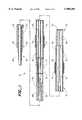
- FIG. 2is a side view of part of another embodiment of a guide wire in accordance with the invention.
- FIG. 3is a partially cut-away side view of the part of the guide wire of FIG. 2;
- FIG. 4is a isometric view of one embodiment of an electrode for use with a guide wire of the invention.
- FIG. 5is a partially cut-away side view of part of yet another embodiment of a guide wire of the invention.
- FIG. 6is a partially cut-away side view of part of yet another embodiment of a guide wire in accordance with the invention.
- FIG. 7is a plan view of yet another embodiment of a guide wire of the invention.
- FIG. 8is a side view of one embodiment of an electrode and insulator in accordance with the invention.
- FIG. 9is an isometric view of another embodiment of an electrode assembly in accordance with the invention.
- FIG. 10is a sectional side view of another embodiment of the guide wire in accordance with the invention, showing the distal portion thereof, and
- FIG. 11is a three-dimensional view of a human heart.
- a guide wire in accordance with one embodiment of the inventionis indicated generally by reference numeral 10, and includes an elongate tubular body 12 defining a central elongate lumen 13.
- the body 12is made of an electrically conductive material which comprises a spring coil 15 towards the distal end 16 of the body 12, and a smooth sleeve section 17 towards the proximal end 18.
- the body 12can equally well be constructed from an electrically non-conductive material.
- the proximal end 18is connected to a rotary connector (not shown).
- Two spaced apart, sleeve-like electrodes 19surround the body 12 near its distal end 16 and an end electrode 20 is located on the distal end 16.
- the electrodes 19are insulated from the spring 15 by insulating sleeves 22, and the electrodes 19, 20 are connected electrically to electrical contacts 24 by means of electrical conductors 26 extending longitudinally along the lumen 13 to the electrical contacts 24 mounted at the proximal end 18 of the tubular body 12.
- a core 28extends along the length of the body 12 and provides the guide wire 10 with structural integrity and a certain amount of rigidity.
- the core 28is tapered towards the distal end 16 to give the wire 10 greater flexibility towards the distal end 16.
- the taperingtakes place in successive gradual steps, one of which is illustrated in FIG. 1 in the portion depicted by reference numeral 30.
- the tapering stepscommence at locations approximately 15 to 20 centimeters from the distal end 16 (not shown), and 2 to 3 centimeters from the distal end 16 (depicted by numeral 30), respectively.
- the core 28is flattened from a point about 1 to 1.5 centimeters from the distal end 16 to define an oval cross section.
- the spring coil 15is also stretched somewhat at its distal end (not shown) to provide the wire 10 with greater flexibility at the distal end 16.
- each electrode 19is electrically insulated from the spring coil 15 by means of a non-conductive support sleeve 22.
- the sleeve 22is adhesively secured to the electrode 19, for example by means of an epoxy or a cyanoacrylate adhesive (not shown).
- the electrode portionis illustrated in greater detail in another embodiment of the guide wire assembly shown in FIGS. 2 and 3.
- the sleeve 34is secured to the spring coil 36 using any suitable means such as adhesive or a heat shrinking process.
- the electrodescan be produced in a variety of ways including wrapping a conductive ribbon around a non-conductive support sleeve.
- a conductive layer spattered onto a non-conductive sleevecan comprise a conductive layer spattered onto a non-conductive sleeve.
- a conductive tube having a longitudinal splitto provide a tubular electrode with a sufficient diameter to allow it to be slipped over an insulator, such as the sleeve 34 and then secured in place by a crimping process or using an adhesive.
- a conductive cylinderhaving a diameter sufficient to be slipped over an insulator such as the sleeve 34 and secured to the sleeve, for example, using an adhesive.
- the electrode 38is shown to be connected to a conductor 40 that passes along the lumen defined by the spring coil 15 to the electrode 19 via a hole 42 formed in the sleeve 34 and a hole 44 in the electrode 38.
- the conductor 40is anchored by means of solder 46.
- the spring 15is slightly stretched in the region of the electrode 34 to permit the conductor 40 to pass through to the electrode 34.
- this embodiment of the guide wirein accordance with the invention, dispenses with the core 28 illustrated in the FIG. 1 embodiment.
- the electrode and its insulatorextend radially from the surface of the coil spring 36, it is preferable to provide a tapered edge to the electrode 34, for example, by using a polymeric material 50 to create a beveled edge to the electrode structure illustrated in FIG. 3. For clarity of illustration the material 50 has not been illustrated in FIG. 2.
- the electrodescan be insulated from the coil spring by means of an insulating layer 52 formed on the inner surface of the cylindrical electrode 54 as illustrated in FIG. 4.
- the electrodecan be insulated from the coil spring by means of an insulating coating 56 formed on the outer surface of the coil spring 58 as illustrated in FIG. 5.
- This coatingcan be formed in only the region occupied by the electrodes or can extend along a greater portion or all of the outer surface of the coil spring.
- the insulating coating 56is indicated as covering the individual coils of the coil spring 58. It will be appreciated that the insulating coating could equally well constitute a sleeve-like structure 60 formed on the coils 62 and having a hole 64 for accommodating the conductor 66.
- FIG. 7is a plan view of part of yet another embodiment of a guide wire in accordance with the invention.
- holes 42 and 44were formed in the sleeve 34 and electrode 38.
- a slot 70can be formed in the electrode 72 as illustrated in FIG. 7.
- the conductor 74then extends through the spaced apart portion 76 of the coil 78 to the center of the electrode 72 via the slot 70.
- the conductor 74is secured to the electrode by means of solder 80. It will be appreciated that instead of providing a slot 70, an embodiment could simply have the conductor secured to an edge of the electrode.
- the electrode 72is, once again, mounted on an insulating layer 82.
- FIGS. 8 to 9Two embodiments of the electrodes formed on an insulating sleeve are depicted in FIGS. 8 to 9.
- FIG. 8shows the electrode 86 in the form of a ribbon 87, wrapped around an insulating tubular support 88.
- the electrodecomprises a split cylinder 90 crimped onto an insulating sleeve 92. (end of tape)
- the spring coil 15 making up the distal part of the body 12is typically coated at its distal end with a radiopaque material, e.g. any of various alloys of platinum, palladium or gold, to make the distal end more easily visible under X-rays.
- the core 28is made of stainless steel or nickel titanium.
- the contacts 24are electrically insulated from the core 28 by means of a sheath 94 of a thin-walled material such as polyamide intermediate the contact 24 and the core 28.
- the contacts 24are secured to the sheath 94 by means of an adhesive 96, for example an epoxy, a moisture cure or a light cure (typically ultra violet light).
- the adhesive 96also serves to smoothen the transition between the contacts 24 and the body 12.
- the electrical conductors 26are secured to the contacts 24 and electrodes 19, 20 by means of a soldering process.
- the wire 10may further include sensors for measuring blood flow velocity in the blood vessel and/or the temperature of blood or tissue.
- sensorsfor measuring blood flow velocity in the blood vessel and/or the temperature of blood or tissue.
- FIG. 10a guide wire 10 having a sensor 100 attached to its distal end 102, is illustrated.
- the sensor 100may be a Doppler ultrasound transducer for measuring the blood flow velocity in a blood vessel or may be any other desired sensor, e.g. for measuring the temperature of tissue.
- the sensor 100is mounted on its own housing 104.
- An electrode 106is secured to the distal end 108 of the spring coil 110 between the coil 110 and the sensor housing 104.
- Conductors 112, connecting the sensor 100 to associated circuitry located externally to the wire 10,extend into the lumen 114 and pass through a central opening 116 in the electrode 106.
- the sensor 100is thus connected electrically to electrical circuitry (not shown), at the proximal end of the body by means of the electrical conductors 112.
- the housing 104is made from an electrically conductive material, the housing 104 is electrically insulated from the electrode 106 by means of a cylindrical insulator 118 intermediate the electrode 106 and the housing 104.
- the core 120serves as a conductor connecting the electrode 106 with a contact (not shown).
- the core 120is provided with an insulating coating (not shown). It will be appreciated that, instead of using the core 120 as a conductor, the electrode 106 could be connected to its contact by means of a separate conductor similar to the conductors 112.
- the guide wire 10has numerous applications. It can, for instance, be used to map electrical activity from any suitable blood vessel e.g. in the heart or the brain. For convenience, the description below refers specifically to the use of the wire 10 in coronary arteries.
- the guide wire 10may be manipulated along a suitable blood vessel into a desired coronary artery to perform functions epicardially.
- the electrodesallow epicardial mapping to be performed by monitoring the electrocardial patterns, as is described in greater detail below. Thereby arrhythmias can be located.
- a sensor attached to the guide wire 10may be used to measure blood flow velocity, temperature or any other variable of interest depending on the nature of the sensor.
- the electrodesperform the further function of ablation by connecting a direct current or radio frequency voltage source to the electrical contacts 24.
- One or more suitable electrodesmay be placed externally to the electrodes on the wire 10 for selective coagulation of body tissue. Instead, a potential difference may be established across any two electrodes on the wire 10 to cause ablation of tissue intermediate these two electrodes.
- the region from which it originatescan be determined generally using electrocardiograms.
- interventionis desired in order to stop the arrhythmia, the precise location must be known.
- current methods for determining the locationinclude percutaneously inserting an electrode catheter into one of the heart chambers and positioning it at various locations on the chamber's endocardial surface to locate the general location of an arrhythmia.
- Another, more accurate, methodrequires open heart surgery in which the chest is opened and the heart exposed. Electrodes are then placed at various points on the epicardial surface. With the present invention, a very precise epicardial approach can be accomplished percutaneously, rather than opening the chest, by inserting the guide wire 10 of the present invention into the coronary arteries, which lie on the epicardial surface of the heart.
- the guide wire 10is used to generate an electrical map of the arterial system of the heart to precisely locate the origin of an arrhythmia, the approximate location of which may have been previously determined through the use of electrodes on the body surface.
- the guide wire 10is steered into any of the coronary arteries or their branches. Access to the arteries is percutaneous using standard techniques either from the femoral or brachial artery.
- Each unipolar electrode on the wireis capable of sensing the local electrical activity of the heart muscle. The activity at various points along the length of an artery, and possibly in several arteries, is sampled as discussed in greater detail below.
- the origin of the arrhythmiais then localized by comparing the sampled signals and determining the earliest occurrence. Any stationary electrode, such as a surface electrode, is used as a reference signal. With multiple electrodes on the wire, multiple sites can be sampled simultaneously. The device thus needs to be repositioned fewer times, and the mapping procedure may be accomplished more quickly.
- intravascular mappingwould involve first locating the general site of the arrhythmia. In this case the electrocardiographic assessment reveals the arrhythmia to be in the tissue served by the left anterior first diagonal artery 130 and left anterior descending artery 132. Now the specific branch needs to be determined. For the purposes of this example, a guide-wire 10 having two unipolar electrodes 19 is used.
- the wire 10is initially positioned with its distal end 16 in the distal region of the second diagonal.
- the two electrodes 19are positioned such that they sample the activity at points 134 and 136.
- An arrhythmiais then induced by applying electrical pulses using an endocardial pacing lead. While the arrhythmia is sustained measurements are made.
- the wire 10is then repositioned into the branch 138 of the second diagonal so that the two electrodes 19 are positioned at points 140 and 142, and the procedure is repeated. This is similarly done for points 144 and 146.
- the wireis then repositioned into the first diagonal branch 130 and the sequence of measurements repeated for points 148 and 150, 152 and 154, and 156 and 158. By comparing the timings of the electrical impulses from all the measurements with reference to a surface electrode, the location of the arrhythmia can be determined by selecting the sample point with the earliest occurrence.
- a general premise for the search procedureis to locate the earliest occurring signal.
- a modification to the mapping procedure just describedcould be to interrogate the arteries, always repositioning the device toward the earlier occurring signal.
- the signals from the two electrodes 19are compared and if the signal from the proximal electrode is earlier, the wire 10 is retracted for the next reading; if the distal signal is earlier, the wire 10 is advanced.
- Embolizationi.e., clogging
- the wire 10is positioned in the branch 138 of the second diagonal so that the distal electrode is approximately at sample point 142.
- the electrodeis then energized with sufficient RF energy to cause heating and coagulation of the blood at and near the electrode site.
- the coagulationwill embolize the artery distal to the electrode.
- Embolizationcan be confirmed by injecting a small amount of contrast medium.
- the brainalso has its own electrical activity which can be demonstrated on electroencephalograms. It will thus be appreciated that the device of the present invention can be used in the cerebral vasculature to map the brain's electrical activity, just as it can in the coronary arteries to map the heart's activity.
- the size and steerability of the wire 10make it ideally suited for the purpose of insertion into even very small veins and arteries.
- the wire 10may be used in conjunction with a catheter tube which is slid over the wire 10 once the appropriate site has been located.
- other flowable materialmay also be fed down the tube to cause, for example cell destruction.
- the tubemay serve to drain flowable material from the site.
- flowable materialincludes not only fluids but also small solid particles dimensioned to pass along the tube e.g. tissue particles which have been removed from the parent tissue, or particles of degenerated material intima.
- wire 10may equally well be used in conjunction with a dilatation balloon or other interventional catheter to treat appropriate problem areas in the same setting as for the mapping and/or ablation procedures.
Landscapes
- Health & Medical Sciences (AREA)
- Life Sciences & Earth Sciences (AREA)
- Engineering & Computer Science (AREA)
- Heart & Thoracic Surgery (AREA)
- Animal Behavior & Ethology (AREA)
- General Health & Medical Sciences (AREA)
- Public Health (AREA)
- Veterinary Medicine (AREA)
- Biomedical Technology (AREA)
- Physics & Mathematics (AREA)
- Surgery (AREA)
- Medical Informatics (AREA)
- Nuclear Medicine, Radiotherapy & Molecular Imaging (AREA)
- Molecular Biology (AREA)
- Biophysics (AREA)
- Pathology (AREA)
- Radiology & Medical Imaging (AREA)
- Vascular Medicine (AREA)
- Cardiology (AREA)
- Thermal Sciences (AREA)
- Physiology (AREA)
- Plasma & Fusion (AREA)
- Otolaryngology (AREA)
- Hematology (AREA)
- Measurement And Recording Of Electrical Phenomena And Electrical Characteristics Of The Living Body (AREA)
- Surgical Instruments (AREA)
Abstract
Description
Claims (27)
Priority Applications (1)
| Application Number | Priority Date | Filing Date | Title |
|---|---|---|---|
| US08/599,223US5908385A (en) | 1994-04-01 | 1996-02-08 | Apparatus for mapping electrical activity in a body and treating tissue |
Applications Claiming Priority (2)
| Application Number | Priority Date | Filing Date | Title |
|---|---|---|---|
| US08/222,137US5517989A (en) | 1994-04-01 | 1994-04-01 | Guidewire assembly |
| US08/599,223US5908385A (en) | 1994-04-01 | 1996-02-08 | Apparatus for mapping electrical activity in a body and treating tissue |
Related Parent Applications (1)
| Application Number | Title | Priority Date | Filing Date |
|---|---|---|---|
| US08/222,137Continuation-In-PartUS5517989A (en) | 1994-04-01 | 1994-04-01 | Guidewire assembly |
Publications (1)
| Publication Number | Publication Date |
|---|---|
| US5908385Atrue US5908385A (en) | 1999-06-01 |
Family
ID=22831005
Family Applications (2)
| Application Number | Title | Priority Date | Filing Date |
|---|---|---|---|
| US08/222,137Expired - Fee RelatedUS5517989A (en) | 1994-04-01 | 1994-04-01 | Guidewire assembly |
| US08/599,223Expired - Fee RelatedUS5908385A (en) | 1994-04-01 | 1996-02-08 | Apparatus for mapping electrical activity in a body and treating tissue |
Family Applications Before (1)
| Application Number | Title | Priority Date | Filing Date |
|---|---|---|---|
| US08/222,137Expired - Fee RelatedUS5517989A (en) | 1994-04-01 | 1994-04-01 | Guidewire assembly |
Country Status (5)
| Country | Link |
|---|---|
| US (2) | US5517989A (en) |
| EP (1) | EP0754008B1 (en) |
| AU (1) | AU1554395A (en) |
| DE (1) | DE69433596D1 (en) |
| WO (1) | WO1995026678A1 (en) |
Cited By (83)
| Publication number | Priority date | Publication date | Assignee | Title |
|---|---|---|---|---|
| US20030014016A1 (en)* | 2001-07-13 | 2003-01-16 | Purdy Phillip D. | Methods and apparatuses for navigating the subaracnhnoid space |
| US20030068152A1 (en)* | 2001-09-10 | 2003-04-10 | Gunn Lawrence Cary | Structure and method for coupling light between dissimilar waveguides |
| US20030097082A1 (en)* | 2001-07-13 | 2003-05-22 | Board Of Regents, The University Of Texas System | Methods and apparatuses for navigating the subarachnoid space |
| US20030109914A1 (en)* | 2000-08-30 | 2003-06-12 | Randy Westlund | Coronary vein leads having an atraumatic TIP and method therefor |
| US6585660B2 (en) | 2001-05-18 | 2003-07-01 | Jomed Inc. | Signal conditioning device for interfacing intravascular sensors having varying operational characteristics to a physiology monitor |
| US20030130577A1 (en)* | 2001-07-13 | 2003-07-10 | Board Of Regents, The University Of Texas System | Introducer sheath |
| US6615067B2 (en)* | 2000-03-21 | 2003-09-02 | Radi Medical Systems Ab | Method and device for measuring physical characteristics in a body |
| US20030216621A1 (en)* | 2002-05-20 | 2003-11-20 | Jomed N.V. | Multipurpose host system for invasive cardiovascular diagnostic measurement acquisition and display |
| US6663570B2 (en) | 2002-02-27 | 2003-12-16 | Volcano Therapeutics, Inc. | Connector for interfacing intravascular sensors to a physiology monitor |
| US6766203B2 (en)* | 2001-04-05 | 2004-07-20 | Pacesetter, Inc. | Body implantable lead with improved tip electrode assembly |
| US20050049510A1 (en)* | 2003-09-02 | 2005-03-03 | Haldeman Paul Craig | Method and apparatus for catheterization by detecting signals indicating proximity to anatomical features |
| US20050137646A1 (en)* | 2003-12-22 | 2005-06-23 | Scimed Life Systems, Inc. | Method of intravascularly delivering stimulation leads into brain |
| US7028387B1 (en) | 2003-03-26 | 2006-04-18 | Advanced Neuromodulation Systems, Inc. | Method of making a miniaturized positional assembly |
| US20060129203A1 (en)* | 2004-12-10 | 2006-06-15 | Scimed Life Systems, Inc. | Methods and kits for delivering cortical electrode leads into patient's head |
| US20070016070A1 (en)* | 2005-05-06 | 2007-01-18 | Sorin Grunwald | Endovascular access and guidance system utilizing divergent beam ultrasound |
| US7177702B2 (en) | 2004-03-12 | 2007-02-13 | Scimed Life Systems, Inc. | Collapsible/expandable electrode leads |
| US7231260B2 (en) | 2004-05-06 | 2007-06-12 | Boston Scientific Scimed, Inc. | Intravascular self-anchoring electrode body with arcuate springs, spring loops, or arms |
| US7286879B2 (en) | 2004-07-16 | 2007-10-23 | Boston Scientific Scimed, Inc. | Method of stimulating fastigium nucleus to treat neurological disorders |
| US7295875B2 (en) | 2004-02-20 | 2007-11-13 | Boston Scientific Scimed, Inc. | Method of stimulating/sensing brain with combination of intravascularly and non-vascularly delivered leads |
| US20080033493A1 (en)* | 2006-08-01 | 2008-02-07 | Gynesonics, Inc. | Peri-capsular fibroid treatment |
| US20090005675A1 (en)* | 2005-05-06 | 2009-01-01 | Sorin Grunwald | Apparatus and Method for Endovascular Device Guiding and Positioning Using Physiological Parameters |
| US20090005774A1 (en)* | 2007-02-09 | 2009-01-01 | Boston Scientific Scimed, Inc. | Medical probe with echogenic and insulative properties |
| US20090088827A1 (en)* | 2007-10-02 | 2009-04-02 | Cardiac Pacemakers, Inc | Lead assembly providing sensing or stimulation of spaced-apart myocardial contact areas |
| US20090099544A1 (en)* | 2007-10-12 | 2009-04-16 | Gynesonics, Inc. | Methods and systems for controlled deployment of needles in tissue |
| US20090118612A1 (en)* | 2005-05-06 | 2009-05-07 | Sorin Grunwald | Apparatus and Method for Vascular Access |
| US7590454B2 (en) | 2004-03-12 | 2009-09-15 | Boston Scientific Neuromodulation Corporation | Modular stimulation lead network |
| US20090287081A1 (en)* | 2008-04-29 | 2009-11-19 | Gynesonics , Inc | Submucosal fibroid ablation for the treatment of menorrhagia |
| US20100056926A1 (en)* | 2008-08-26 | 2010-03-04 | Gynesonics, Inc. | Ablation device with articulated imaging transducer |
| US20100222677A1 (en)* | 2009-02-27 | 2010-09-02 | Gynesonics, Inc. | Needle and tine deployment mechanism |
| US8019441B2 (en) | 2004-03-12 | 2011-09-13 | Boston Scientific Neuromodulation Corporation | Collapsible/expandable tubular electrode leads |
| US8060207B2 (en) | 2003-12-22 | 2011-11-15 | Boston Scientific Scimed, Inc. | Method of intravascularly delivering stimulation leads into direct contact with tissue |
| US20120041342A1 (en)* | 2010-08-16 | 2012-02-16 | Abbott Cardiovascular Systems Inc. | High durability coronary guide wire |
| US8206300B2 (en) | 2008-08-26 | 2012-06-26 | Gynesonics, Inc. | Ablation device with articulated imaging transducer |
| US8388546B2 (en) | 2006-10-23 | 2013-03-05 | Bard Access Systems, Inc. | Method of locating the tip of a central venous catheter |
| US8388541B2 (en) | 2007-11-26 | 2013-03-05 | C. R. Bard, Inc. | Integrated system for intravascular placement of a catheter |
| US20130079616A1 (en)* | 2005-11-22 | 2013-03-28 | Mayo Foundation For Medical Education And Research | Detecting and treating nervous system disorders |
| US8437833B2 (en) | 2008-10-07 | 2013-05-07 | Bard Access Systems, Inc. | Percutaneous magnetic gastrostomy |
| US8478382B2 (en) | 2008-02-11 | 2013-07-02 | C. R. Bard, Inc. | Systems and methods for positioning a catheter |
| US8512256B2 (en) | 2006-10-23 | 2013-08-20 | Bard Access Systems, Inc. | Method of locating the tip of a central venous catheter |
| USD699359S1 (en) | 2011-08-09 | 2014-02-11 | C. R. Bard, Inc. | Ultrasound probe head |
| US8781555B2 (en) | 2007-11-26 | 2014-07-15 | C. R. Bard, Inc. | System for placement of a catheter including a signal-generating stylet |
| US8784336B2 (en) | 2005-08-24 | 2014-07-22 | C. R. Bard, Inc. | Stylet apparatuses and methods of manufacture |
| US8801693B2 (en) | 2010-10-29 | 2014-08-12 | C. R. Bard, Inc. | Bioimpedance-assisted placement of a medical device |
| US8849382B2 (en) | 2007-11-26 | 2014-09-30 | C. R. Bard, Inc. | Apparatus and display methods relating to intravascular placement of a catheter |
| WO2015013638A1 (en)* | 2013-07-26 | 2015-01-29 | Volcano Corporation | Connection structures for intravascular devices and associated systems and methods |
| US8965490B2 (en) | 2012-05-07 | 2015-02-24 | Vasonova, Inc. | Systems and methods for detection of the superior vena cava area |
| USD724745S1 (en) | 2011-08-09 | 2015-03-17 | C. R. Bard, Inc. | Cap for an ultrasound probe |
| US9119551B2 (en) | 2010-11-08 | 2015-09-01 | Vasonova, Inc. | Endovascular navigation system and method |
| US9125578B2 (en) | 2009-06-12 | 2015-09-08 | Bard Access Systems, Inc. | Apparatus and method for catheter navigation and tip location |
| US9211107B2 (en) | 2011-11-07 | 2015-12-15 | C. R. Bard, Inc. | Ruggedized ultrasound hydrogel insert |
| US9339206B2 (en) | 2009-06-12 | 2016-05-17 | Bard Access Systems, Inc. | Adaptor for endovascular electrocardiography |
| US9445734B2 (en) | 2009-06-12 | 2016-09-20 | Bard Access Systems, Inc. | Devices and methods for endovascular electrography |
| US9456766B2 (en) | 2007-11-26 | 2016-10-04 | C. R. Bard, Inc. | Apparatus for use with needle insertion guidance system |
| US9492097B2 (en) | 2007-11-26 | 2016-11-15 | C. R. Bard, Inc. | Needle length determination and calibration for insertion guidance system |
| US9521961B2 (en) | 2007-11-26 | 2016-12-20 | C. R. Bard, Inc. | Systems and methods for guiding a medical instrument |
| US9532724B2 (en) | 2009-06-12 | 2017-01-03 | Bard Access Systems, Inc. | Apparatus and method for catheter navigation using endovascular energy mapping |
| US9554716B2 (en) | 2007-11-26 | 2017-01-31 | C. R. Bard, Inc. | Insertion guidance system for needles and medical components |
| US9597480B2 (en) | 2009-10-07 | 2017-03-21 | Endophys Holding, LLC | Intraluminal devices and systems |
| US9636031B2 (en) | 2007-11-26 | 2017-05-02 | C.R. Bard, Inc. | Stylets for use with apparatus for intravascular placement of a catheter |
| US9649048B2 (en) | 2007-11-26 | 2017-05-16 | C. R. Bard, Inc. | Systems and methods for breaching a sterile field for intravascular placement of a catheter |
| US9839372B2 (en) | 2014-02-06 | 2017-12-12 | C. R. Bard, Inc. | Systems and methods for guidance and placement of an intravascular device |
| US9901714B2 (en) | 2008-08-22 | 2018-02-27 | C. R. Bard, Inc. | Catheter assembly including ECG sensor and magnetic assemblies |
| US10046139B2 (en) | 2010-08-20 | 2018-08-14 | C. R. Bard, Inc. | Reconfirmation of ECG-assisted catheter tip placement |
| US10258240B1 (en) | 2014-11-24 | 2019-04-16 | Vascular Imaging Corporation | Optical fiber pressure sensor |
| US10327645B2 (en) | 2013-10-04 | 2019-06-25 | Vascular Imaging Corporation | Imaging techniques using an imaging guidewire |
| US10349890B2 (en) | 2015-06-26 | 2019-07-16 | C. R. Bard, Inc. | Connector interface for ECG-based catheter positioning system |
| US10449330B2 (en) | 2007-11-26 | 2019-10-22 | C. R. Bard, Inc. | Magnetic element-equipped needle assemblies |
| US10506934B2 (en) | 2012-05-25 | 2019-12-17 | Phyzhon Health Inc. | Optical fiber pressure sensor |
| US10524691B2 (en) | 2007-11-26 | 2020-01-07 | C. R. Bard, Inc. | Needle assembly including an aligned magnetic element |
| US10537255B2 (en) | 2013-11-21 | 2020-01-21 | Phyzhon Health Inc. | Optical fiber pressure sensor |
| US10595819B2 (en) | 2006-04-20 | 2020-03-24 | Gynesonics, Inc. | Ablation device with articulated imaging transducer |
| US10639008B2 (en) | 2009-10-08 | 2020-05-05 | C. R. Bard, Inc. | Support and cover structures for an ultrasound probe head |
| US10751509B2 (en) | 2007-11-26 | 2020-08-25 | C. R. Bard, Inc. | Iconic representations for guidance of an indwelling medical device |
| US10820885B2 (en) | 2012-06-15 | 2020-11-03 | C. R. Bard, Inc. | Apparatus and methods for detection of a removable cap on an ultrasound probe |
| US10888232B2 (en) | 2011-08-20 | 2021-01-12 | Philips Image Guided Therapy Corporation | Devices, systems, and methods for assessing a vessel |
| US10953204B2 (en) | 2017-01-09 | 2021-03-23 | Boston Scientific Scimed, Inc. | Guidewire with tactile feel |
| US10973584B2 (en) | 2015-01-19 | 2021-04-13 | Bard Access Systems, Inc. | Device and method for vascular access |
| US10992079B2 (en) | 2018-10-16 | 2021-04-27 | Bard Access Systems, Inc. | Safety-equipped connection systems and methods thereof for establishing electrical connections |
| US10993770B2 (en) | 2016-11-11 | 2021-05-04 | Gynesonics, Inc. | Controlled treatment of tissue and dynamic interaction with, and comparison of, tissue and/or treatment data |
| US11000207B2 (en) | 2016-01-29 | 2021-05-11 | C. R. Bard, Inc. | Multiple coil system for tracking a medical device |
| US11103213B2 (en) | 2009-10-08 | 2021-08-31 | C. R. Bard, Inc. | Spacers for use with an ultrasound probe |
| US11122980B2 (en) | 2011-08-20 | 2021-09-21 | Imperial College Of Science, Technology And Medicine | Devices, systems, and methods for visually depicting a vessel and evaluating treatment options |
| US20220280754A1 (en)* | 2021-03-04 | 2022-09-08 | Covidien Lp | Sleeve for an endoscope and/or catheter including a helical design |
Families Citing this family (65)
| Publication number | Priority date | Publication date | Assignee | Title |
|---|---|---|---|---|
| US5517989A (en)* | 1994-04-01 | 1996-05-21 | Cardiometrics, Inc. | Guidewire assembly |
| DE69534748T2 (en)* | 1994-09-02 | 2006-11-02 | Volcano Corp. (n.d, Ges.d.Staates Delaware), Rancho Cordova | ULTRAMINIATUR PRESSURE SENSOR AND GUIDE WIRE THEREFORE |
| US5782760A (en)* | 1995-05-23 | 1998-07-21 | Cardima, Inc. | Over-the-wire EP catheter |
| US6002956A (en)* | 1995-05-23 | 1999-12-14 | Cardima, Inc. | Method of treating using an over-the-wire EP catheter |
| US5895355A (en)* | 1995-05-23 | 1999-04-20 | Cardima, Inc. | Over-the-wire EP catheter |
| US5984907A (en)* | 1995-06-05 | 1999-11-16 | Ep Technologies, Inc. | Transition sleeve assembly for catheters |
| US5716389A (en)* | 1995-11-13 | 1998-02-10 | Walinsky; Paul | Cardiac ablation catheter arrangement with movable guidewire |
| AU710236B2 (en)* | 1996-01-08 | 1999-09-16 | Biosense, Inc. | Cardiac electro-mechanics |
| US5779643A (en)* | 1996-11-26 | 1998-07-14 | Hewlett-Packard Company | Imaging guidewire with back and forth sweeping ultrasonic source |
| US6464697B1 (en) | 1998-02-19 | 2002-10-15 | Curon Medical, Inc. | Stomach and adjoining tissue regions in the esophagus |
| US5701901A (en)* | 1996-11-26 | 1997-12-30 | Hewlett Packard Company | Ultrasonic probe with back and forth sweeping ultrasonic source |
| US6602247B2 (en) | 1997-02-27 | 2003-08-05 | Cryocath Technologies Inc. | Apparatus and method for performing a treatment on a selected tissue region |
| US5899898A (en)* | 1997-02-27 | 1999-05-04 | Cryocath Technologies Inc. | Cryosurgical linear ablation |
| DE19721362B4 (en)* | 1997-04-01 | 2011-05-26 | Axel Muntermann | Device and calibration method for catheter ablation |
| US6522930B1 (en)* | 1998-05-06 | 2003-02-18 | Atrionix, Inc. | Irrigated ablation device assembly |
| US6142958A (en) | 1998-12-23 | 2000-11-07 | Radi Medical Systems Ab | Sensor and guide wire assembly |
| SE520276C2 (en) | 1999-01-25 | 2003-06-17 | Elekta Ab | Device for controlled tissue destruction |
| US6210339B1 (en)* | 1999-03-03 | 2001-04-03 | Endosonics Corporation | Flexible elongate member having one or more electrical contacts |
| FR2790966B1 (en) | 1999-03-17 | 2001-05-04 | Ela Medical Sa | LEFT EARCUTE STIMULATION PROBE IMPLANTABLE IN THE CORONARY VENOUS NETWORK FOR ACTIVE IMPLANTABLE MEDICAL DEVICE, IN PARTICULAR "MULTISITE" TYPE STIMULATOR |
| US6607520B2 (en)* | 1999-09-15 | 2003-08-19 | The General Hospital Corporation | Coiled ablation catheter system |
| US20060095032A1 (en) | 1999-11-16 | 2006-05-04 | Jerome Jackson | Methods and systems for determining physiologic characteristics for treatment of the esophagus |
| US20040215235A1 (en) | 1999-11-16 | 2004-10-28 | Barrx, Inc. | Methods and systems for determining physiologic characteristics for treatment of the esophagus |
| WO2001035846A1 (en) | 1999-11-16 | 2001-05-25 | Ganz Robert A | System and method of treating abnormal tissue in the human esophagus |
| GB0104982D0 (en)* | 2001-02-28 | 2001-04-18 | Gill Steven | Electrode |
| US8579825B2 (en)* | 2001-06-15 | 2013-11-12 | Radi Medical Systems Ab | Electrically conductive guide wire |
| JP4222775B2 (en)* | 2001-06-15 | 2009-02-12 | ラディ・メディカル・システムズ・アクチェボラーグ | Measuring device that can be inserted into living organisms |
| DE10132332A1 (en)* | 2001-07-02 | 2003-02-06 | Heiko Fiebig | Isometric exercise machine has two handles with holes through and joined by cable, with cable-clamps with hole through and screw fixtures |
| US7486994B2 (en)* | 2002-09-13 | 2009-02-03 | Cardiac Pacemakers, Inc. | Method and device for supporting or strengthening a portion of a lead |
| US20070260282A1 (en)* | 2003-09-12 | 2007-11-08 | Taylor William J | Feedthrough apparatus with noble metal-coated leads |
| US7747314B2 (en)* | 2003-12-30 | 2010-06-29 | Boston Scientific Scimed, Inc. | Distal assembly for a medical device |
| US7150745B2 (en) | 2004-01-09 | 2006-12-19 | Barrx Medical, Inc. | Devices and methods for treatment of luminal tissue |
| US20060135953A1 (en)* | 2004-12-22 | 2006-06-22 | Wlodzimierz Kania | Tissue ablation system including guidewire with sensing element |
| US7997278B2 (en) | 2005-11-23 | 2011-08-16 | Barrx Medical, Inc. | Precision ablating method |
| US7959627B2 (en) | 2005-11-23 | 2011-06-14 | Barrx Medical, Inc. | Precision ablating device |
| US8702694B2 (en) | 2005-11-23 | 2014-04-22 | Covidien Lp | Auto-aligning ablating device and method of use |
| US20080091528A1 (en) | 2006-07-28 | 2008-04-17 | Alastair Rampell | Methods and systems for an alternative payment platform |
| WO2008131017A2 (en)* | 2007-04-16 | 2008-10-30 | C. R. Bard, Inc. | Guidewire-assisted catheter placement system |
| US8641711B2 (en) | 2007-05-04 | 2014-02-04 | Covidien Lp | Method and apparatus for gastrointestinal tract ablation for treatment of obesity |
| US8784338B2 (en) | 2007-06-22 | 2014-07-22 | Covidien Lp | Electrical means to normalize ablational energy transmission to a luminal tissue surface of varying size |
| WO2009009443A1 (en) | 2007-07-06 | 2009-01-15 | Barrx Medical, Inc. | Method and apparatus for gastrointestinal tract ablation to achieve loss of persistent and/or recurrent excess body weight following a weight-loss operation |
| CN102688092B (en) | 2007-07-06 | 2015-04-22 | 柯惠有限合伙公司 | Ablation in the gastrointestinal tract to achieve hemostasis and eradicate lesions with a propensity for bleeding |
| US8273012B2 (en) | 2007-07-30 | 2012-09-25 | Tyco Healthcare Group, Lp | Cleaning device and methods |
| US8646460B2 (en) | 2007-07-30 | 2014-02-11 | Covidien Lp | Cleaning device and methods |
| WO2012067935A1 (en)* | 2010-11-18 | 2012-05-24 | Cardiac Pacemakers, Inc. | Guidewire and signal analyzer for pacing site optimization |
| US10278774B2 (en) | 2011-03-18 | 2019-05-07 | Covidien Lp | Selectively expandable operative element support structure and methods of use |
| US9717554B2 (en) | 2012-03-26 | 2017-08-01 | Biosense Webster (Israel) Ltd. | Catheter with composite construction |
| WO2013144717A1 (en)* | 2012-03-28 | 2013-10-03 | St. Jude Medical Systems Ab | Sensor guide wire comprising a polymer layer |
| US20130310673A1 (en)* | 2012-05-17 | 2013-11-21 | Assaf Govari | Guide wire with position sensing electrodes |
| US10639099B2 (en) | 2012-05-25 | 2020-05-05 | Biosense Webster (Israel), Ltd. | Catheter having a distal section with spring sections for biased deflection |
| WO2014005007A1 (en)* | 2012-06-28 | 2014-01-03 | Volcano Corporation | Side-loading connectors for use with intravascular devices and associated systems and methods |
| US10835183B2 (en) | 2013-07-01 | 2020-11-17 | Zurich Medical Corporation | Apparatus and method for intravascular measurements |
| JP5976983B1 (en) | 2013-07-01 | 2016-08-24 | ズーリック・メディカル・コーポレイションZurich Medical Corporation | Apparatus and method for intravascular measurement |
| US10448986B2 (en)* | 2013-09-27 | 2019-10-22 | Covidien Lp | Electrosurgical medical device with power modulation |
| US9763733B2 (en) | 2013-10-25 | 2017-09-19 | Covidien Lp | Unfurling electrode devices with the multiple longitudinal electrode segments |
| US9743981B2 (en) | 2013-10-25 | 2017-08-29 | Covidien Lp | Unfurling electrode devices with spring |
| JP6751842B2 (en)* | 2014-11-28 | 2020-09-09 | 三友集団株式会社 | Biological heating equipment |
| US10368934B2 (en) | 2015-01-14 | 2019-08-06 | Covidien Lp | Arrangement of multi-channel bipolar electrode zones to minimize leakage and edge effects |
| US10149716B2 (en) | 2015-02-02 | 2018-12-11 | Covidien Lp | Self-sizing catheter features to prevent over-tightening of the electrode |
| US20160310041A1 (en)* | 2015-04-22 | 2016-10-27 | Acclarent, Inc. | Guidewire with navigation sensor |
| WO2017136746A1 (en) | 2016-02-03 | 2017-08-10 | Cormetrics Llc | Modular sensing guidewire |
| US12161822B2 (en)* | 2018-04-30 | 2024-12-10 | Board Of Regents Of The University Of Texas System | Introduction device including an electroactive tip on a guidewire |
| US11173285B2 (en)* | 2018-06-28 | 2021-11-16 | Biosense Webster (Israel) Ltd. | Producing a guidewire comprising a position sensor |
| US11471650B2 (en) | 2019-09-20 | 2022-10-18 | Biosense Webster (Israel) Ltd. | Mechanism for manipulating a puller wire |
| US20240108287A1 (en) | 2019-10-18 | 2024-04-04 | Boston Scientific Medical Device Limited | Medical guidewire assembly and/or electrical connector |
| JP7634016B2 (en)* | 2020-01-28 | 2025-02-20 | ジャイラス エーシーエムアイ インク ディー/ビー/エー オリンパス サージカル テクノロジーズ アメリカ | Medical device with biliary diagnostic device |
Citations (2)
| Publication number | Priority date | Publication date | Assignee | Title |
|---|---|---|---|---|
| US5509411A (en)* | 1993-01-29 | 1996-04-23 | Cardima, Inc. | Intravascular sensing device |
| US5517989A (en)* | 1994-04-01 | 1996-05-21 | Cardiometrics, Inc. | Guidewire assembly |
Family Cites Families (26)
| Publication number | Priority date | Publication date | Assignee | Title |
|---|---|---|---|---|
| US4481953A (en)* | 1981-11-12 | 1984-11-13 | Cordis Corporation | Endocardial lead having helically wound ribbon electrode |
| US4660571A (en)* | 1985-07-18 | 1987-04-28 | Cordis Corporation | Percutaneous lead having radially adjustable electrode |
| JPS62207435A (en)* | 1986-03-07 | 1987-09-11 | テルモ株式会社 | Catheter for measuring cardiac output |
| US4771788A (en)* | 1986-07-18 | 1988-09-20 | Pfizer Hospital Products Group, Inc. | Doppler tip wire guide |
| JP2653792B2 (en)* | 1986-07-18 | 1997-09-17 | ハウメディカ・インコーポレーテッド | Blood velocity measurement wire guide |
| US4920967A (en)* | 1986-07-18 | 1990-05-01 | Pfizer Hospital Products Group, Inc. | Doppler tip wire guide |
| US4991588A (en)* | 1986-07-21 | 1991-02-12 | Pfizer Hospital Products Group, Inc. | Doppler guide wire |
| US5105818A (en)* | 1987-04-10 | 1992-04-21 | Cardiometric, Inc. | Apparatus, system and method for measuring spatial average velocity and/or volumetric flow of blood in a vessel and screw joint for use therewith |
| US4967753A (en)* | 1987-04-10 | 1990-11-06 | Cardiometrics, Inc. | Apparatus, system and method for measuring spatial average velocity and/or volumetric flow of blood in a vessel |
| US5174295A (en)* | 1987-04-10 | 1992-12-29 | Cardiometrics, Inc. | Apparatus, system and method for measuring spatial average velocity and/or volumetric flow of blood in a vessel and screw joint for use therewith |
| US5163445A (en)* | 1987-04-10 | 1992-11-17 | Cardiometrics, Inc. | Apparatus, system and method for measuring spatial average velocity and/or volumetric flow of blood in a vessel and screw joint for use therewith |
| US4961433A (en)* | 1988-11-02 | 1990-10-09 | Cardiometrics, Inc. | Guide wire assembly with electrical functions and male and female connectors for use therewith |
| US5178159A (en)* | 1988-11-02 | 1993-01-12 | Cardiometrics, Inc. | Torqueable guide wire assembly with electrical functions, male and female connectors rotatable with respect to one another |
| US4945912A (en)* | 1988-11-25 | 1990-08-07 | Sensor Electronics, Inc. | Catheter with radiofrequency heating applicator |
| US4957110A (en)* | 1989-03-17 | 1990-09-18 | C. R. Bard, Inc. | Steerable guidewire having electrodes for measuring vessel cross-section and blood flow |
| US4936281A (en)* | 1989-04-13 | 1990-06-26 | Everest Medical Corporation | Ultrasonically enhanced RF ablation catheter |
| US5098431A (en)* | 1989-04-13 | 1992-03-24 | Everest Medical Corporation | RF ablation catheter |
| US5104393A (en)* | 1989-08-30 | 1992-04-14 | Angelase, Inc. | Catheter |
| US5059851A (en)* | 1990-09-06 | 1991-10-22 | Cardiometrics, Inc. | Miniature ultrasound high efficiency transducer assembly, guidewire using the same and method |
| US5125137A (en)* | 1990-09-06 | 1992-06-30 | Cardiometrics, Inc. | Method for providing a miniature ultrasound high efficiency transducer assembly |
| US5156151A (en)* | 1991-02-15 | 1992-10-20 | Cardiac Pathways Corporation | Endocardial mapping and ablation system and catheter probe |
| US5184621A (en)* | 1991-05-29 | 1993-02-09 | C. R. Bard, Inc. | Steerable guidewire having electrodes for measuring vessel cross-section and blood flow |
| US5174299A (en)* | 1991-08-12 | 1992-12-29 | Cardiac Pacemakers, Inc. | Thermocouple-based blood flow sensor |
| US5257451A (en)* | 1991-11-08 | 1993-11-02 | Ep Technologies, Inc. | Method of making durable sleeve for enclosing a bendable electrode tip assembly |
| US5327905A (en)* | 1992-02-14 | 1994-07-12 | Boaz Avitall | Biplanar deflectable catheter for arrhythmogenic tissue ablation |
| US5318525A (en)* | 1992-04-10 | 1994-06-07 | Medtronic Cardiorhythm | Steerable electrode catheter |
- 1994
- 1994-04-01USUS08/222,137patent/US5517989A/ennot_activeExpired - Fee Related
- 1994-12-23DEDE69433596Tpatent/DE69433596D1/ennot_activeExpired - Lifetime
- 1994-12-23EPEP95907250Apatent/EP0754008B1/ennot_activeExpired - Lifetime
- 1994-12-23WOPCT/US1994/014865patent/WO1995026678A1/enactiveIP Right Grant
- 1994-12-23AUAU15543/95Apatent/AU1554395A/ennot_activeAbandoned
- 1996
- 1996-02-08USUS08/599,223patent/US5908385A/ennot_activeExpired - Fee Related
Patent Citations (2)
| Publication number | Priority date | Publication date | Assignee | Title |
|---|---|---|---|---|
| US5509411A (en)* | 1993-01-29 | 1996-04-23 | Cardima, Inc. | Intravascular sensing device |
| US5517989A (en)* | 1994-04-01 | 1996-05-21 | Cardiometrics, Inc. | Guidewire assembly |
Cited By (195)
| Publication number | Priority date | Publication date | Assignee | Title |
|---|---|---|---|---|
| US6615067B2 (en)* | 2000-03-21 | 2003-09-02 | Radi Medical Systems Ab | Method and device for measuring physical characteristics in a body |
| US20100049288A1 (en)* | 2000-08-30 | 2010-02-25 | Randy Westlund | Coronary vein lead having pre-formed biased portions for fixation |
| US8050775B2 (en) | 2000-08-30 | 2011-11-01 | Cardiac Pacemakers, Inc. | Coronary vein lead having pre-formed biased portions for fixation |
| US20030109914A1 (en)* | 2000-08-30 | 2003-06-12 | Randy Westlund | Coronary vein leads having an atraumatic TIP and method therefor |
| US20070067008A1 (en)* | 2000-08-30 | 2007-03-22 | Cardiac Pacemakers, Inc. | Leads for pacing and/or sensing the heart from within the coronary veins |
| US20030195603A1 (en)* | 2000-08-30 | 2003-10-16 | Cardiac Pacemakers, Inc. | Leads for pacing and/or sensing the heart from within the coronary veins |
| US8498721B2 (en) | 2000-08-30 | 2013-07-30 | Cardiac Pacemakers, Inc. | Coronary vein leads having pre-formed biased portions for fixation |
| US7628801B2 (en)* | 2000-08-30 | 2009-12-08 | Cardiac Pacemakers, Inc. | Coronary vein leads having an atraumatic tip and method therefor |
| US7139614B2 (en) | 2000-08-30 | 2006-11-21 | Cardiac Pacemakers, Inc. | Leads for pacing and/or sensing the heart from within the coronary veins |
| US6766203B2 (en)* | 2001-04-05 | 2004-07-20 | Pacesetter, Inc. | Body implantable lead with improved tip electrode assembly |
| US6585660B2 (en) | 2001-05-18 | 2003-07-01 | Jomed Inc. | Signal conditioning device for interfacing intravascular sensors having varying operational characteristics to a physiology monitor |
| WO2003005908A3 (en)* | 2001-07-13 | 2003-12-11 | Univ Texas | Methods and apparatuses for navigating the subarachnoid space |
| US10315013B2 (en) | 2001-07-13 | 2019-06-11 | Endophys Holdings, Llc | Sheath with sensing capabilities |
| US20090076357A1 (en)* | 2001-07-13 | 2009-03-19 | Purdy Phillip D | Methods and Apparatuses for Navigating the Subaracnhnoid Space |
| US8961452B2 (en) | 2001-07-13 | 2015-02-24 | Board Of Regents, The University Of Texas System | Multi-sheath member apparatus |
| US7011647B2 (en) | 2001-07-13 | 2006-03-14 | Scimed Life Systems, Inc. | Introducer sheath |
| US7787954B2 (en) | 2001-07-13 | 2010-08-31 | Board Of Regents, The University Of Texas System | Methods and apparatuses for navigating the subaracnhnoid space |
| US7455666B2 (en) | 2001-07-13 | 2008-11-25 | Board Of Regents, The University Of Texas System | Methods and apparatuses for navigating the subarachnoid space |
| US20030130577A1 (en)* | 2001-07-13 | 2003-07-10 | Board Of Regents, The University Of Texas System | Introducer sheath |
| US20100324397A1 (en)* | 2001-07-13 | 2010-12-23 | Purdy Phillip D | Methods and Apparatuses for Navigating the Subaracnhnoid Space |
| US7150737B2 (en) | 2001-07-13 | 2006-12-19 | Sci/Med Life Systems, Inc. | Methods and apparatuses for navigating the subarachnoid space |
| US20030097082A1 (en)* | 2001-07-13 | 2003-05-22 | Board Of Regents, The University Of Texas System | Methods and apparatuses for navigating the subarachnoid space |
| US10716921B2 (en) | 2001-07-13 | 2020-07-21 | Endophys Holdings, Llc | Methods of using a dual-lumen sheath in intraluminal procedures |
| US20030014016A1 (en)* | 2001-07-13 | 2003-01-16 | Purdy Phillip D. | Methods and apparatuses for navigating the subaracnhnoid space |
| US8131353B2 (en) | 2001-07-13 | 2012-03-06 | Board Of Regents, The University Of Texas System | Methods and apparatuses for navigating the subarachnoid space |
| US20030068152A1 (en)* | 2001-09-10 | 2003-04-10 | Gunn Lawrence Cary | Structure and method for coupling light between dissimilar waveguides |
| US7274956B2 (en) | 2002-02-27 | 2007-09-25 | Volcano Corporation | Connector for interfacing intravascular sensors to a physiology monitor |
| US20040082866A1 (en)* | 2002-02-27 | 2004-04-29 | Mott Eric V. | Connector for interfacing intravascular sensors to a physiology monitor |
| US6663570B2 (en) | 2002-02-27 | 2003-12-16 | Volcano Therapeutics, Inc. | Connector for interfacing intravascular sensors to a physiology monitor |
| US20070060822A1 (en)* | 2002-05-20 | 2007-03-15 | Volcano Corp. | Multipurpose host system for invasive cardiovascular diagnostic measurement acquisition and display |
| US8636659B2 (en) | 2002-05-20 | 2014-01-28 | Volcano Corporation | Multipurpose host system for invasive cardiovascular diagnostic measurement acquisition and display |
| US20030216621A1 (en)* | 2002-05-20 | 2003-11-20 | Jomed N.V. | Multipurpose host system for invasive cardiovascular diagnostic measurement acquisition and display |
| US7134994B2 (en) | 2002-05-20 | 2006-11-14 | Volcano Corporation | Multipurpose host system for invasive cardiovascular diagnostic measurement acquisition and display |
| US8556820B2 (en) | 2002-05-20 | 2013-10-15 | Volcano Corporation | Multipurpose host system for invasive cardiovascular diagnostic measurement acquisition and display |
| US8562537B2 (en) | 2002-05-20 | 2013-10-22 | Volcano Corporation | Multipurpose host system for invasive cardiovascular diagnostic measurement acquisition and display |
| US7028387B1 (en) | 2003-03-26 | 2006-04-18 | Advanced Neuromodulation Systems, Inc. | Method of making a miniaturized positional assembly |
| US8000771B2 (en)* | 2003-09-02 | 2011-08-16 | Cardiac Pacemakers, Inc. | Method and apparatus for catheterization by detecting signals indicating proximity to anatomical features |
| US20050049510A1 (en)* | 2003-09-02 | 2005-03-03 | Haldeman Paul Craig | Method and apparatus for catheterization by detecting signals indicating proximity to anatomical features |
| US8060207B2 (en) | 2003-12-22 | 2011-11-15 | Boston Scientific Scimed, Inc. | Method of intravascularly delivering stimulation leads into direct contact with tissue |
| US20070135861A1 (en)* | 2003-12-22 | 2007-06-14 | Boston Scientific Scimed, Inc. | Method of intravascularly delivering stimulation leads into brain to stimulate the spg |
| US20050137646A1 (en)* | 2003-12-22 | 2005-06-23 | Scimed Life Systems, Inc. | Method of intravascularly delivering stimulation leads into brain |
| US7818063B2 (en) | 2003-12-22 | 2010-10-19 | Boston Scientific Scimed, Inc. | Method of intravascularly delivering stimulation leads into brain to stimulate the SPG |
| US7295875B2 (en) | 2004-02-20 | 2007-11-13 | Boston Scientific Scimed, Inc. | Method of stimulating/sensing brain with combination of intravascularly and non-vascularly delivered leads |
| US20090319012A1 (en)* | 2004-03-12 | 2009-12-24 | Boston Scientific Neuromodulation Corporation | Modular stimulation lead network |
| US8185208B2 (en) | 2004-03-12 | 2012-05-22 | Boston Scientific Neuromodulation Corporation | Modular stimulation lead network |
| US8019441B2 (en) | 2004-03-12 | 2011-09-13 | Boston Scientific Neuromodulation Corporation | Collapsible/expandable tubular electrode leads |
| US7177702B2 (en) | 2004-03-12 | 2007-02-13 | Scimed Life Systems, Inc. | Collapsible/expandable electrode leads |
| US7590454B2 (en) | 2004-03-12 | 2009-09-15 | Boston Scientific Neuromodulation Corporation | Modular stimulation lead network |
| US7231260B2 (en) | 2004-05-06 | 2007-06-12 | Boston Scientific Scimed, Inc. | Intravascular self-anchoring electrode body with arcuate springs, spring loops, or arms |
| US8103350B2 (en) | 2004-07-16 | 2012-01-24 | Boston Scientific Neuromodulation Corporation | Method of stimulation fastigium nucleus to treat neurological disorders |
| US8731674B2 (en) | 2004-07-16 | 2014-05-20 | Boston Scientific Neuromodulation Corporation | Method of stimulating fastigium nucleus to treat neurological disorders |
| US7286879B2 (en) | 2004-07-16 | 2007-10-23 | Boston Scientific Scimed, Inc. | Method of stimulating fastigium nucleus to treat neurological disorders |
| US20060129203A1 (en)* | 2004-12-10 | 2006-06-15 | Scimed Life Systems, Inc. | Methods and kits for delivering cortical electrode leads into patient's head |
| US7937160B2 (en) | 2004-12-10 | 2011-05-03 | Boston Scientific Neuromodulation Corporation | Methods for delivering cortical electrode leads into patient's head |
| US20090005675A1 (en)* | 2005-05-06 | 2009-01-01 | Sorin Grunwald | Apparatus and Method for Endovascular Device Guiding and Positioning Using Physiological Parameters |
| US20070016072A1 (en)* | 2005-05-06 | 2007-01-18 | Sorin Grunwald | Endovenous access and guidance system utilizing non-image based ultrasound |
| US8597193B2 (en) | 2005-05-06 | 2013-12-03 | Vasonova, Inc. | Apparatus and method for endovascular device guiding and positioning using physiological parameters |
| US9339207B2 (en) | 2005-05-06 | 2016-05-17 | Vasonova, Inc. | Endovascular devices and methods of use |
| US9204819B2 (en) | 2005-05-06 | 2015-12-08 | Vasonova, Inc. | Endovenous access and guidance system utilizing non-image based ultrasound |
| US10321890B2 (en) | 2005-05-06 | 2019-06-18 | Arrow International, Inc. | Apparatus and method for endovascular device guiding and positioning using physiological parameters |
| US20070016068A1 (en)* | 2005-05-06 | 2007-01-18 | Sorin Grunwald | Ultrasound methods of positioning guided vascular access devices in the venous system |
| US9198600B2 (en) | 2005-05-06 | 2015-12-01 | Vasonova, Inc. | Endovascular access and guidance system utilizing divergent beam ultrasound |
| US20090118612A1 (en)* | 2005-05-06 | 2009-05-07 | Sorin Grunwald | Apparatus and Method for Vascular Access |
| US10335240B2 (en) | 2005-05-06 | 2019-07-02 | Arrow International, Inc. | Endovascular navigation system and method |
| US10368837B2 (en) | 2005-05-06 | 2019-08-06 | Arrow International, Inc. | Apparatus and method for vascular access |
| US20090177090A1 (en)* | 2005-05-06 | 2009-07-09 | Sorin Grunwald | Endovascular devices and methods of use |
| US20070016069A1 (en)* | 2005-05-06 | 2007-01-18 | Sorin Grunwald | Ultrasound sensor |
| US12150716B2 (en) | 2005-05-06 | 2024-11-26 | Teleflex Life Sciences Llc | Endovascular navigation system and method |
| US20070016070A1 (en)* | 2005-05-06 | 2007-01-18 | Sorin Grunwald | Endovascular access and guidance system utilizing divergent beam ultrasound |
| US8409103B2 (en) | 2005-05-06 | 2013-04-02 | Vasonova, Inc. | Ultrasound methods of positioning guided vascular access devices in the venous system |
| US10470743B2 (en) | 2005-05-06 | 2019-11-12 | Arrow International, Inc. | Apparatus and method for endovascular device guiding and positioning using physiological parameters |
| US8784336B2 (en) | 2005-08-24 | 2014-07-22 | C. R. Bard, Inc. | Stylet apparatuses and methods of manufacture |
| US11207496B2 (en) | 2005-08-24 | 2021-12-28 | C. R. Bard, Inc. | Stylet apparatuses and methods of manufacture |
| US10004875B2 (en) | 2005-08-24 | 2018-06-26 | C. R. Bard, Inc. | Stylet apparatuses and methods of manufacture |
| US9414762B2 (en) | 2005-11-22 | 2016-08-16 | Mayo Foundation For Medical Education And Research | Detecting and treating nervous system disorders |
| US20130079616A1 (en)* | 2005-11-22 | 2013-03-28 | Mayo Foundation For Medical Education And Research | Detecting and treating nervous system disorders |
| US8812099B2 (en)* | 2005-11-22 | 2014-08-19 | Mayo Foundation For Medical Education And Research | Detecting and treating nervous system disorders |
| US12048583B2 (en) | 2006-04-20 | 2024-07-30 | Gynesonics, Inc. | Ablation device with articulated imaging transducer |
| US10610197B2 (en) | 2006-04-20 | 2020-04-07 | Gynesonics, Inc. | Ablation device with articulated imaging transducer |
| US10595819B2 (en) | 2006-04-20 | 2020-03-24 | Gynesonics, Inc. | Ablation device with articulated imaging transducer |
| US8298145B2 (en)* | 2006-08-01 | 2012-10-30 | Gynesonics, Inc. | Peri-capsular fibroid treatment |
| US20080033493A1 (en)* | 2006-08-01 | 2008-02-07 | Gynesonics, Inc. | Peri-capsular fibroid treatment |
| US9833169B2 (en) | 2006-10-23 | 2017-12-05 | Bard Access Systems, Inc. | Method of locating the tip of a central venous catheter |
| US8512256B2 (en) | 2006-10-23 | 2013-08-20 | Bard Access Systems, Inc. | Method of locating the tip of a central venous catheter |
| US8774907B2 (en) | 2006-10-23 | 2014-07-08 | Bard Access Systems, Inc. | Method of locating the tip of a central venous catheter |
| US9345422B2 (en) | 2006-10-23 | 2016-05-24 | Bard Acess Systems, Inc. | Method of locating the tip of a central venous catheter |
| US8388546B2 (en) | 2006-10-23 | 2013-03-05 | Bard Access Systems, Inc. | Method of locating the tip of a central venous catheter |
| US9265443B2 (en) | 2006-10-23 | 2016-02-23 | Bard Access Systems, Inc. | Method of locating the tip of a central venous catheter |
| US8858455B2 (en) | 2006-10-23 | 2014-10-14 | Bard Access Systems, Inc. | Method of locating the tip of a central venous catheter |
| US9498282B2 (en)* | 2007-02-09 | 2016-11-22 | Boston Scientific Scimed, Inc. | Medical probe with echogenic and insulative properties |
| US20090005774A1 (en)* | 2007-02-09 | 2009-01-01 | Boston Scientific Scimed, Inc. | Medical probe with echogenic and insulative properties |
| US20090088827A1 (en)* | 2007-10-02 | 2009-04-02 | Cardiac Pacemakers, Inc | Lead assembly providing sensing or stimulation of spaced-apart myocardial contact areas |
| US11925512B2 (en) | 2007-10-12 | 2024-03-12 | Gynesonics, Inc. | Methods and systems for controlled deployment of needles in tissue |
| US20090099544A1 (en)* | 2007-10-12 | 2009-04-16 | Gynesonics, Inc. | Methods and systems for controlled deployment of needles in tissue |
| US8088072B2 (en) | 2007-10-12 | 2012-01-03 | Gynesonics, Inc. | Methods and systems for controlled deployment of needles in tissue |
| US11826207B2 (en) | 2007-10-12 | 2023-11-28 | Gynesonics, Inc | Methods and systems for controlled deployment of needles in tissue |
| US11096760B2 (en) | 2007-10-12 | 2021-08-24 | Gynesonics, Inc. | Methods and systems for controlled deployment of needles in tissue |
| US8262577B2 (en) | 2007-10-12 | 2012-09-11 | Gynesonics, Inc. | Methods and systems for controlled deployment of needles in tissue |
| US11096761B2 (en) | 2007-10-12 | 2021-08-24 | Gynesonics, Inc. | Methods and systems for controlled deployment of needles in tissue |
| US10449330B2 (en) | 2007-11-26 | 2019-10-22 | C. R. Bard, Inc. | Magnetic element-equipped needle assemblies |
| US8388541B2 (en) | 2007-11-26 | 2013-03-05 | C. R. Bard, Inc. | Integrated system for intravascular placement of a catheter |
| US8849382B2 (en) | 2007-11-26 | 2014-09-30 | C. R. Bard, Inc. | Apparatus and display methods relating to intravascular placement of a catheter |
| US8781555B2 (en) | 2007-11-26 | 2014-07-15 | C. R. Bard, Inc. | System for placement of a catheter including a signal-generating stylet |
| US11779240B2 (en) | 2007-11-26 | 2023-10-10 | C. R. Bard, Inc. | Systems and methods for breaching a sterile field for intravascular placement of a catheter |
| US11707205B2 (en) | 2007-11-26 | 2023-07-25 | C. R. Bard, Inc. | Integrated system for intravascular placement of a catheter |
| US11529070B2 (en) | 2007-11-26 | 2022-12-20 | C. R. Bard, Inc. | System and methods for guiding a medical instrument |
| US9456766B2 (en) | 2007-11-26 | 2016-10-04 | C. R. Bard, Inc. | Apparatus for use with needle insertion guidance system |
| US9492097B2 (en) | 2007-11-26 | 2016-11-15 | C. R. Bard, Inc. | Needle length determination and calibration for insertion guidance system |
| US10524691B2 (en) | 2007-11-26 | 2020-01-07 | C. R. Bard, Inc. | Needle assembly including an aligned magnetic element |
| US9521961B2 (en) | 2007-11-26 | 2016-12-20 | C. R. Bard, Inc. | Systems and methods for guiding a medical instrument |
| US9526440B2 (en) | 2007-11-26 | 2016-12-27 | C.R. Bard, Inc. | System for placement of a catheter including a signal-generating stylet |
| US11134915B2 (en) | 2007-11-26 | 2021-10-05 | C. R. Bard, Inc. | System for placement of a catheter including a signal-generating stylet |
| US9549685B2 (en) | 2007-11-26 | 2017-01-24 | C. R. Bard, Inc. | Apparatus and display methods relating to intravascular placement of a catheter |
| US9554716B2 (en) | 2007-11-26 | 2017-01-31 | C. R. Bard, Inc. | Insertion guidance system for needles and medical components |
| US11123099B2 (en) | 2007-11-26 | 2021-09-21 | C. R. Bard, Inc. | Apparatus for use with needle insertion guidance system |
| US9636031B2 (en) | 2007-11-26 | 2017-05-02 | C.R. Bard, Inc. | Stylets for use with apparatus for intravascular placement of a catheter |
| US9649048B2 (en) | 2007-11-26 | 2017-05-16 | C. R. Bard, Inc. | Systems and methods for breaching a sterile field for intravascular placement of a catheter |
| US9681823B2 (en) | 2007-11-26 | 2017-06-20 | C. R. Bard, Inc. | Integrated system for intravascular placement of a catheter |
| US10342575B2 (en) | 2007-11-26 | 2019-07-09 | C. R. Bard, Inc. | Apparatus for use with needle insertion guidance system |
| US10238418B2 (en) | 2007-11-26 | 2019-03-26 | C. R. Bard, Inc. | Apparatus for use with needle insertion guidance system |
| US10966630B2 (en) | 2007-11-26 | 2021-04-06 | C. R. Bard, Inc. | Integrated system for intravascular placement of a catheter |
| US10849695B2 (en) | 2007-11-26 | 2020-12-01 | C. R. Bard, Inc. | Systems and methods for breaching a sterile field for intravascular placement of a catheter |
| US10602958B2 (en) | 2007-11-26 | 2020-03-31 | C. R. Bard, Inc. | Systems and methods for guiding a medical instrument |
| US10231753B2 (en) | 2007-11-26 | 2019-03-19 | C. R. Bard, Inc. | Insertion guidance system for needles and medical components |
| US10751509B2 (en) | 2007-11-26 | 2020-08-25 | C. R. Bard, Inc. | Iconic representations for guidance of an indwelling medical device |
| US9999371B2 (en) | 2007-11-26 | 2018-06-19 | C. R. Bard, Inc. | Integrated system for intravascular placement of a catheter |
| US10165962B2 (en) | 2007-11-26 | 2019-01-01 | C. R. Bard, Inc. | Integrated systems for intravascular placement of a catheter |
| US10105121B2 (en) | 2007-11-26 | 2018-10-23 | C. R. Bard, Inc. | System for placement of a catheter including a signal-generating stylet |
| US8478382B2 (en) | 2008-02-11 | 2013-07-02 | C. R. Bard, Inc. | Systems and methods for positioning a catheter |
| US8971994B2 (en) | 2008-02-11 | 2015-03-03 | C. R. Bard, Inc. | Systems and methods for positioning a catheter |
| US20090287081A1 (en)* | 2008-04-29 | 2009-11-19 | Gynesonics , Inc | Submucosal fibroid ablation for the treatment of menorrhagia |
| US9901714B2 (en) | 2008-08-22 | 2018-02-27 | C. R. Bard, Inc. | Catheter assembly including ECG sensor and magnetic assemblies |
| US11027101B2 (en) | 2008-08-22 | 2021-06-08 | C. R. Bard, Inc. | Catheter assembly including ECG sensor and magnetic assemblies |
| US8206300B2 (en) | 2008-08-26 | 2012-06-26 | Gynesonics, Inc. | Ablation device with articulated imaging transducer |
| US20100056926A1 (en)* | 2008-08-26 | 2010-03-04 | Gynesonics, Inc. | Ablation device with articulated imaging transducer |
| US8437833B2 (en) | 2008-10-07 | 2013-05-07 | Bard Access Systems, Inc. | Percutaneous magnetic gastrostomy |
| US9907513B2 (en) | 2008-10-07 | 2018-03-06 | Bard Access Systems, Inc. | Percutaneous magnetic gastrostomy |
| US8262574B2 (en) | 2009-02-27 | 2012-09-11 | Gynesonics, Inc. | Needle and tine deployment mechanism |
| US11564735B2 (en) | 2009-02-27 | 2023-01-31 | Gynesonics, Inc. | Needle and fine deployment mechanism |
| US11992258B2 (en) | 2009-02-27 | 2024-05-28 | Gynesonics, Inc. | Needle and tine deployment mechanism |
| US20100222677A1 (en)* | 2009-02-27 | 2010-09-02 | Gynesonics, Inc. | Needle and tine deployment mechanism |
| US10321951B2 (en) | 2009-02-27 | 2019-06-18 | Gynesonics, Inc. | Needle and tine deployment mechanism |
| US9125578B2 (en) | 2009-06-12 | 2015-09-08 | Bard Access Systems, Inc. | Apparatus and method for catheter navigation and tip location |
| US10349857B2 (en) | 2009-06-12 | 2019-07-16 | Bard Access Systems, Inc. | Devices and methods for endovascular electrography |
| US9339206B2 (en) | 2009-06-12 | 2016-05-17 | Bard Access Systems, Inc. | Adaptor for endovascular electrocardiography |
| US10912488B2 (en) | 2009-06-12 | 2021-02-09 | Bard Access Systems, Inc. | Apparatus and method for catheter navigation and tip location |
| US10271762B2 (en) | 2009-06-12 | 2019-04-30 | Bard Access Systems, Inc. | Apparatus and method for catheter navigation using endovascular energy mapping |
| US9445734B2 (en) | 2009-06-12 | 2016-09-20 | Bard Access Systems, Inc. | Devices and methods for endovascular electrography |
| US9532724B2 (en) | 2009-06-12 | 2017-01-03 | Bard Access Systems, Inc. | Apparatus and method for catheter navigation using endovascular energy mapping |
| US10231643B2 (en) | 2009-06-12 | 2019-03-19 | Bard Access Systems, Inc. | Apparatus and method for catheter navigation and tip location |
| US11419517B2 (en) | 2009-06-12 | 2022-08-23 | Bard Access Systems, Inc. | Apparatus and method for catheter navigation using endovascular energy mapping |
| US9597480B2 (en) | 2009-10-07 | 2017-03-21 | Endophys Holding, LLC | Intraluminal devices and systems |
| US9913959B2 (en) | 2009-10-07 | 2018-03-13 | Endophys Holdings, Llc | Device configured for real-time pressure sensing |
| US10639008B2 (en) | 2009-10-08 | 2020-05-05 | C. R. Bard, Inc. | Support and cover structures for an ultrasound probe head |
| US11998386B2 (en) | 2009-10-08 | 2024-06-04 | C. R. Bard, Inc. | Support and cover structures for an ultrasound probe head |
| US11103213B2 (en) | 2009-10-08 | 2021-08-31 | C. R. Bard, Inc. | Spacers for use with an ultrasound probe |
| US20120041342A1 (en)* | 2010-08-16 | 2012-02-16 | Abbott Cardiovascular Systems Inc. | High durability coronary guide wire |
| US10046139B2 (en) | 2010-08-20 | 2018-08-14 | C. R. Bard, Inc. | Reconfirmation of ECG-assisted catheter tip placement |
| US9415188B2 (en) | 2010-10-29 | 2016-08-16 | C. R. Bard, Inc. | Bioimpedance-assisted placement of a medical device |
| US8801693B2 (en) | 2010-10-29 | 2014-08-12 | C. R. Bard, Inc. | Bioimpedance-assisted placement of a medical device |
| US11445996B2 (en) | 2010-11-08 | 2022-09-20 | Teleflex Life Sciences Limited | Endovascular navigation system and method |
| US10368830B2 (en) | 2010-11-08 | 2019-08-06 | Arrow International Inc. | Endovascular navigation system and method |
| US9119551B2 (en) | 2010-11-08 | 2015-09-01 | Vasonova, Inc. | Endovascular navigation system and method |
| USD699359S1 (en) | 2011-08-09 | 2014-02-11 | C. R. Bard, Inc. | Ultrasound probe head |
| USD754357S1 (en) | 2011-08-09 | 2016-04-19 | C. R. Bard, Inc. | Ultrasound probe head |
| USD724745S1 (en) | 2011-08-09 | 2015-03-17 | C. R. Bard, Inc. | Cap for an ultrasound probe |
| US11122980B2 (en) | 2011-08-20 | 2021-09-21 | Imperial College Of Science, Technology And Medicine | Devices, systems, and methods for visually depicting a vessel and evaluating treatment options |
| US10888232B2 (en) | 2011-08-20 | 2021-01-12 | Philips Image Guided Therapy Corporation | Devices, systems, and methods for assessing a vessel |
| US9211107B2 (en) | 2011-11-07 | 2015-12-15 | C. R. Bard, Inc. | Ruggedized ultrasound hydrogel insert |
| US9743994B2 (en) | 2012-05-07 | 2017-08-29 | Vasonova, Inc. | Right atrium indicator |
| US8965490B2 (en) | 2012-05-07 | 2015-02-24 | Vasonova, Inc. | Systems and methods for detection of the superior vena cava area |
| US9345447B2 (en) | 2012-05-07 | 2016-05-24 | Vasonova, Inc. | Right atrium indicator |
| US11172833B2 (en) | 2012-05-25 | 2021-11-16 | Phyzhon Health Inc. | Optical fiber pressure sensor guidewire |
| US10506934B2 (en) | 2012-05-25 | 2019-12-17 | Phyzhon Health Inc. | Optical fiber pressure sensor |
| US10820885B2 (en) | 2012-06-15 | 2020-11-03 | C. R. Bard, Inc. | Apparatus and methods for detection of a removable cap on an ultrasound probe |
| US9878142B2 (en) | 2013-07-26 | 2018-01-30 | Volcano Corporation | Connection structures for intravascular devices and associated systems and methods |
| WO2015013638A1 (en)* | 2013-07-26 | 2015-01-29 | Volcano Corporation | Connection structures for intravascular devices and associated systems and methods |
| US11298026B2 (en) | 2013-10-04 | 2022-04-12 | Phyzhon Health Inc. | Imaging techniques using an imaging guidewire |
| US10327645B2 (en) | 2013-10-04 | 2019-06-25 | Vascular Imaging Corporation | Imaging techniques using an imaging guidewire |
| US10537255B2 (en) | 2013-11-21 | 2020-01-21 | Phyzhon Health Inc. | Optical fiber pressure sensor |
| US11696692B2 (en) | 2013-11-21 | 2023-07-11 | Phyzhon Health Inc. | Optical fiber pressure sensor |
| US9839372B2 (en) | 2014-02-06 | 2017-12-12 | C. R. Bard, Inc. | Systems and methods for guidance and placement of an intravascular device |
| US10863920B2 (en) | 2014-02-06 | 2020-12-15 | C. R. Bard, Inc. | Systems and methods for guidance and placement of an intravascular device |
| US10258240B1 (en) | 2014-11-24 | 2019-04-16 | Vascular Imaging Corporation | Optical fiber pressure sensor |
| US10973584B2 (en) | 2015-01-19 | 2021-04-13 | Bard Access Systems, Inc. | Device and method for vascular access |
| US10349890B2 (en) | 2015-06-26 | 2019-07-16 | C. R. Bard, Inc. | Connector interface for ECG-based catheter positioning system |
| US11026630B2 (en) | 2015-06-26 | 2021-06-08 | C. R. Bard, Inc. | Connector interface for ECG-based catheter positioning system |
| US11000207B2 (en) | 2016-01-29 | 2021-05-11 | C. R. Bard, Inc. | Multiple coil system for tracking a medical device |
| US11419682B2 (en) | 2016-11-11 | 2022-08-23 | Gynesonics, Inc. | Controlled treatment of tissue and dynamic interaction with, and comparison of, tissue and/or treatment data |
| US10993770B2 (en) | 2016-11-11 | 2021-05-04 | Gynesonics, Inc. | Controlled treatment of tissue and dynamic interaction with, and comparison of, tissue and/or treatment data |
| US12239382B2 (en) | 2016-11-11 | 2025-03-04 | Gynesonics, Inc. | Controlled treatment of tissue and dynamic interaction with, and comparison of, tissue and/or treatment data |
| US10953204B2 (en) | 2017-01-09 | 2021-03-23 | Boston Scientific Scimed, Inc. | Guidewire with tactile feel |
| US11621518B2 (en) | 2018-10-16 | 2023-04-04 | Bard Access Systems, Inc. | Safety-equipped connection systems and methods thereof for establishing electrical connections |
| US10992079B2 (en) | 2018-10-16 | 2021-04-27 | Bard Access Systems, Inc. | Safety-equipped connection systems and methods thereof for establishing electrical connections |
| US20220280754A1 (en)* | 2021-03-04 | 2022-09-08 | Covidien Lp | Sleeve for an endoscope and/or catheter including a helical design |
Also Published As
| Publication number | Publication date |
|---|---|
| AU1554395A (en) | 1995-10-23 |
| EP0754008A4 (en) | 1998-07-01 |
| US5517989A (en) | 1996-05-21 |
| WO1995026678A1 (en) | 1995-10-12 |
| EP0754008B1 (en) | 2004-03-03 |
| DE69433596D1 (en) | 2004-04-08 |
| EP0754008A1 (en) | 1997-01-22 |
Similar Documents
| Publication | Publication Date | Title |
|---|---|---|
| US5908385A (en) | Apparatus for mapping electrical activity in a body and treating tissue | |
| US20210177510A1 (en) | Catheter with irrigated tip electrode with porous substrate and high density surface micro-electrodes | |
| US5699796A (en) | High resolution intravascular signal detection | |
| JP3488716B2 (en) | Tube sensing device | |
| US6251107B1 (en) | Ep catheter | |
| US6096035A (en) | Multipolar transmural probe | |
| US5056517A (en) | Biomagnetically localizable multipurpose catheter and method for magnetocardiographic guided intracardiac mapping, biopsy and ablation of cardiac arrhythmias | |
| JP4447073B2 (en) | Multi-element tip electrode mapping catheter | |
| JP3094895B2 (en) | Ablation catheter | |
| US6308090B1 (en) | Devices and methods for coronary sinus mapping | |
| US5951471A (en) | Catheter-based coronary sinus mapping and ablation | |
| DE69419172T2 (en) | ELECTRODE ARRANGEMENT FOR CATHETER | |
| EP3000390A1 (en) | High resolution electrophysiology catheter | |
| CN114246669A (en) | Basket catheter with insulated ablation and diagnostic electrodes | |
| AU701125B2 (en) | A multipolar transmural probe |
Legal Events
| Date | Code | Title | Description |
|---|---|---|---|
| AS | Assignment | Owner name:SEIKO EPSON CORPORATION, JAPAN Free format text:ASSIGNMENT OF ASSIGNORS INTEREST;ASSIGNORS:OGATA, HIDEAKI;TANIMOTO, AKIHITO;NAKAOKA, YASUSHI;AND OTHERS;REEL/FRAME:007899/0552;SIGNING DATES FROM 19960409 TO 19960411 | |
| AS | Assignment | Owner name:CARDIOMETRICS, INC., CALIFORNIA Free format text:ASSIGNMENT OF ASSIGNORS INTEREST;ASSIGNORS:CHECHELSKI, VICTOR;FRISBLE, JEFFREY S.;CORL, PAUL D.;AND OTHERS;REEL/FRAME:007973/0966 Effective date:19960426 | |
| FEPP | Fee payment procedure | Free format text:PAT HOLDER NO LONGER CLAIMS SMALL ENTITY STATUS, ENTITY STATUS SET TO UNDISCOUNTED (ORIGINAL EVENT CODE: STOL); ENTITY STATUS OF PATENT OWNER: LARGE ENTITY | |
| FPAY | Fee payment | Year of fee payment:4 | |
| AS | Assignment | Owner name:JOMED, INC., CALIFORNIA Free format text:ASSIGNMENT OF ASSIGNORS INTEREST;ASSIGNOR:CARDIOMETRICS, INC.;REEL/FRAME:013986/0139 Effective date:20030717 Owner name:VOLCANO THERAPEUTICS INC., CALIFORNIA Free format text:ASSIGNMENT OF ASSIGNORS INTEREST;ASSIGNOR:JOMED INC.;REEL/FRAME:013986/0229 Effective date:20030717 | |
| AS | Assignment | Owner name:VOLCANO THERAPEUTICS, INC., CALIFORNIA Free format text:ASSIGNMENT OF ASSIGNORS INTEREST;ASSIGNOR:JOMED INC.;REEL/FRAME:014539/0729 Effective date:20030717 Owner name:VOLCANO THERAPEUTICS, INC.,CALIFORNIA Free format text:ASSIGNMENT OF ASSIGNORS INTEREST;ASSIGNOR:JOMED INC.;REEL/FRAME:014539/0729 Effective date:20030717 | |
| AS | Assignment | Owner name:VOLCANO CORPORATION, CALIFORNIA Free format text:CHANGE OF NAME;ASSIGNOR:VOLCANO THERAPEUTICS, INC.;REEL/FRAME:016686/0799 Effective date:20041014 | |
| REMI | Maintenance fee reminder mailed | ||
| LAPS | Lapse for failure to pay maintenance fees | ||
| STCH | Information on status: patent discontinuation | Free format text:PATENT EXPIRED DUE TO NONPAYMENT OF MAINTENANCE FEES UNDER 37 CFR 1.362 | |
| FP | Lapsed due to failure to pay maintenance fee | Effective date:20070601 |