US5907600A - Product registration system - Google Patents
Product registration systemDownload PDFInfo
- Publication number
- US5907600A US5907600AUS08/429,907US42990795AUS5907600AUS 5907600 AUS5907600 AUS 5907600AUS 42990795 AUS42990795 AUS 42990795AUS 5907600 AUS5907600 AUS 5907600A
- Authority
- US
- United States
- Prior art keywords
- product
- station
- identifying information
- information
- user
- Prior art date
- Legal status (The legal status is an assumption and is not a legal conclusion. Google has not performed a legal analysis and makes no representation as to the accuracy of the status listed.)
- Expired - Lifetime
Links
Images


Classifications
- H—ELECTRICITY
- H04—ELECTRIC COMMUNICATION TECHNIQUE
- H04W—WIRELESS COMMUNICATION NETWORKS
- H04W4/00—Services specially adapted for wireless communication networks; Facilities therefor
- H04W4/16—Communication-related supplementary services, e.g. call-transfer or call-hold
- H—ELECTRICITY
- H04—ELECTRIC COMMUNICATION TECHNIQUE
- H04M—TELEPHONIC COMMUNICATION
- H04M1/00—Substation equipment, e.g. for use by subscribers
- H04M1/006—Call diverting means
- H—ELECTRICITY
- H04—ELECTRIC COMMUNICATION TECHNIQUE
- H04M—TELEPHONIC COMMUNICATION
- H04M1/00—Substation equipment, e.g. for use by subscribers
- H04M1/26—Devices for calling a subscriber
- H04M1/27—Devices whereby a plurality of signals may be stored simultaneously
- H—ELECTRICITY
- H04—ELECTRIC COMMUNICATION TECHNIQUE
- H04M—TELEPHONIC COMMUNICATION
- H04M1/00—Substation equipment, e.g. for use by subscribers
- H04M1/64—Automatic arrangements for answering calls; Automatic arrangements for recording messages for absent subscribers; Arrangements for recording conversations
- H04M1/65—Recording arrangements for recording a message from the calling party
- H04M1/652—Means for playing back the recorded messages by remote control over a telephone line
- H—ELECTRICITY
- H04—ELECTRIC COMMUNICATION TECHNIQUE
- H04M—TELEPHONIC COMMUNICATION
- H04M1/00—Substation equipment, e.g. for use by subscribers
- H04M1/64—Automatic arrangements for answering calls; Automatic arrangements for recording messages for absent subscribers; Arrangements for recording conversations
- H04M1/65—Recording arrangements for recording a message from the calling party
- H04M1/658—Means for redirecting recorded messages to other extensions or equipment
- H—ELECTRICITY
- H04—ELECTRIC COMMUNICATION TECHNIQUE
- H04M—TELEPHONIC COMMUNICATION
- H04M1/00—Substation equipment, e.g. for use by subscribers
- H04M1/66—Substation equipment, e.g. for use by subscribers with means for preventing unauthorised or fraudulent calling
- H04M1/663—Preventing unauthorised calls to a telephone set
- H04M1/665—Preventing unauthorised calls to a telephone set by checking the validity of a code
- H—ELECTRICITY
- H04—ELECTRIC COMMUNICATION TECHNIQUE
- H04M—TELEPHONIC COMMUNICATION
- H04M11/00—Telephonic communication systems specially adapted for combination with other electrical systems
- H—ELECTRICITY
- H04—ELECTRIC COMMUNICATION TECHNIQUE
- H04M—TELEPHONIC COMMUNICATION
- H04M11/00—Telephonic communication systems specially adapted for combination with other electrical systems
- H04M11/02—Telephonic communication systems specially adapted for combination with other electrical systems with bell or annunciator systems
- H04M11/022—Paging systems
- H—ELECTRICITY
- H04—ELECTRIC COMMUNICATION TECHNIQUE
- H04M—TELEPHONIC COMMUNICATION
- H04M3/00—Automatic or semi-automatic exchanges
- H04M3/38—Graded-service arrangements, i.e. some subscribers prevented from establishing certain connections
- H04M3/382—Graded-service arrangements, i.e. some subscribers prevented from establishing certain connections using authorisation codes or passwords
- H—ELECTRICITY
- H04—ELECTRIC COMMUNICATION TECHNIQUE
- H04M—TELEPHONIC COMMUNICATION
- H04M3/00—Automatic or semi-automatic exchanges
- H04M3/42—Systems providing special services or facilities to subscribers
- H—ELECTRICITY
- H04—ELECTRIC COMMUNICATION TECHNIQUE
- H04M—TELEPHONIC COMMUNICATION
- H04M3/00—Automatic or semi-automatic exchanges
- H04M3/42—Systems providing special services or facilities to subscribers
- H04M3/42229—Personal communication services, i.e. services related to one subscriber independent of his terminal and/or location
- H—ELECTRICITY
- H04—ELECTRIC COMMUNICATION TECHNIQUE
- H04M—TELEPHONIC COMMUNICATION
- H04M3/00—Automatic or semi-automatic exchanges
- H04M3/42—Systems providing special services or facilities to subscribers
- H04M3/428—Arrangements for placing incoming calls on hold
- H—ELECTRICITY
- H04—ELECTRIC COMMUNICATION TECHNIQUE
- H04M—TELEPHONIC COMMUNICATION
- H04M3/00—Automatic or semi-automatic exchanges
- H04M3/42—Systems providing special services or facilities to subscribers
- H04M3/436—Arrangements for screening incoming calls, i.e. evaluating the characteristics of a call before deciding whether to answer it
- H—ELECTRICITY
- H04—ELECTRIC COMMUNICATION TECHNIQUE
- H04M—TELEPHONIC COMMUNICATION
- H04M3/00—Automatic or semi-automatic exchanges
- H04M3/42—Systems providing special services or facilities to subscribers
- H04M3/50—Centralised arrangements for answering calls; Centralised arrangements for recording messages for absent or busy subscribers ; Centralised arrangements for recording messages
- H04M3/527—Centralised call answering arrangements not requiring operator intervention
- H—ELECTRICITY
- H04—ELECTRIC COMMUNICATION TECHNIQUE
- H04M—TELEPHONIC COMMUNICATION
- H04M3/00—Automatic or semi-automatic exchanges
- H04M3/42—Systems providing special services or facilities to subscribers
- H04M3/54—Arrangements for diverting calls for one subscriber to another predetermined subscriber
- H—ELECTRICITY
- H04—ELECTRIC COMMUNICATION TECHNIQUE
- H04Q—SELECTING
- H04Q11/00—Selecting arrangements for multiplex systems
- H04Q11/04—Selecting arrangements for multiplex systems for time-division multiplexing
- H04Q11/0428—Integrated services digital network, i.e. systems for transmission of different types of digitised signals, e.g. speech, data, telecentral, television signals
- H04Q11/0435—Details
- H04Q11/0457—Connection protocols
- H—ELECTRICITY
- H04—ELECTRIC COMMUNICATION TECHNIQUE
- H04Q—SELECTING
- H04Q3/00—Selecting arrangements
- H04Q3/0016—Arrangements providing connection between exchanges
- H04Q3/0029—Provisions for intelligent networking
- H04Q3/005—Personal communication services, e.g. provisions for portability of subscriber numbers
- H—ELECTRICITY
- H04—ELECTRIC COMMUNICATION TECHNIQUE
- H04Q—SELECTING
- H04Q3/00—Selecting arrangements
- H04Q3/42—Circuit arrangements for indirect selecting controlled by common circuits, e.g. register controller, marker
- H04Q3/54—Circuit arrangements for indirect selecting controlled by common circuits, e.g. register controller, marker in which the logic circuitry controlling the exchange is centralised
- H04Q3/542—Logic circuits or arrangements therefor
- H—ELECTRICITY
- H04—ELECTRIC COMMUNICATION TECHNIQUE
- H04Q—SELECTING
- H04Q3/00—Selecting arrangements
- H04Q3/42—Circuit arrangements for indirect selecting controlled by common circuits, e.g. register controller, marker
- H04Q3/54—Circuit arrangements for indirect selecting controlled by common circuits, e.g. register controller, marker in which the logic circuitry controlling the exchange is centralised
- H04Q3/545—Circuit arrangements for indirect selecting controlled by common circuits, e.g. register controller, marker in which the logic circuitry controlling the exchange is centralised using a stored programme
- H04Q3/54508—Configuration, initialisation
- H04Q3/54525—Features introduction
- H—ELECTRICITY
- H04—ELECTRIC COMMUNICATION TECHNIQUE
- H04Q—SELECTING
- H04Q3/00—Selecting arrangements
- H04Q3/42—Circuit arrangements for indirect selecting controlled by common circuits, e.g. register controller, marker
- H04Q3/54—Circuit arrangements for indirect selecting controlled by common circuits, e.g. register controller, marker in which the logic circuitry controlling the exchange is centralised
- H04Q3/545—Circuit arrangements for indirect selecting controlled by common circuits, e.g. register controller, marker in which the logic circuitry controlling the exchange is centralised using a stored programme
- H04Q3/54541—Circuit arrangements for indirect selecting controlled by common circuits, e.g. register controller, marker in which the logic circuitry controlling the exchange is centralised using a stored programme using multi-processor systems
- H04Q3/54566—Intelligent peripherals, adjunct processors
- H—ELECTRICITY
- H04—ELECTRIC COMMUNICATION TECHNIQUE
- H04Q—SELECTING
- H04Q3/00—Selecting arrangements
- H04Q3/42—Circuit arrangements for indirect selecting controlled by common circuits, e.g. register controller, marker
- H04Q3/54—Circuit arrangements for indirect selecting controlled by common circuits, e.g. register controller, marker in which the logic circuitry controlling the exchange is centralised
- H04Q3/545—Circuit arrangements for indirect selecting controlled by common circuits, e.g. register controller, marker in which the logic circuitry controlling the exchange is centralised using a stored programme
- H04Q3/54575—Software application
- H04Q3/54591—Supervision, e.g. fault localisation, traffic measurements, avoiding errors, failure recovery, monitoring, statistical analysis
- H—ELECTRICITY
- H04—ELECTRIC COMMUNICATION TECHNIQUE
- H04Q—SELECTING
- H04Q3/00—Selecting arrangements
- H04Q3/58—Arrangements providing connection between main exchange and sub-exchange or satellite
- H04Q3/62—Arrangements providing connection between main exchange and sub-exchange or satellite for connecting to private branch exchanges
- H04Q3/622—Circuit arrangements therefor
- H—ELECTRICITY
- H04—ELECTRIC COMMUNICATION TECHNIQUE
- H04Q—SELECTING
- H04Q3/00—Selecting arrangements
- H04Q3/58—Arrangements providing connection between main exchange and sub-exchange or satellite
- H04Q3/62—Arrangements providing connection between main exchange and sub-exchange or satellite for connecting to private branch exchanges
- H04Q3/625—Arrangements in the private branch exchange
- H04Q3/627—Details
- H—ELECTRICITY
- H04—ELECTRIC COMMUNICATION TECHNIQUE
- H04W—WIRELESS COMMUNICATION NETWORKS
- H04W76/00—Connection management
- H04W76/10—Connection setup
- H—ELECTRICITY
- H04—ELECTRIC COMMUNICATION TECHNIQUE
- H04M—TELEPHONIC COMMUNICATION
- H04M2203/00—Aspects of automatic or semi-automatic exchanges
- H04M2203/20—Aspects of automatic or semi-automatic exchanges related to features of supplementary services
- H04M2203/2005—Temporarily overriding a service configuration
- H—ELECTRICITY
- H04—ELECTRIC COMMUNICATION TECHNIQUE
- H04M—TELEPHONIC COMMUNICATION
- H04M2203/00—Aspects of automatic or semi-automatic exchanges
- H04M2203/20—Aspects of automatic or semi-automatic exchanges related to features of supplementary services
- H04M2203/2011—Service processing based on information specified by a party before or during a call, e.g. information, tone or routing selection
- H—ELECTRICITY
- H04—ELECTRIC COMMUNICATION TECHNIQUE
- H04M—TELEPHONIC COMMUNICATION
- H04M2203/00—Aspects of automatic or semi-automatic exchanges
- H04M2203/20—Aspects of automatic or semi-automatic exchanges related to features of supplementary services
- H04M2203/2072—Schedules, e.g. personal calendars
- H—ELECTRICITY
- H04—ELECTRIC COMMUNICATION TECHNIQUE
- H04M—TELEPHONIC COMMUNICATION
- H04M2242/00—Special services or facilities
- H04M2242/22—Automatic class or number identification arrangements
- H—ELECTRICITY
- H04—ELECTRIC COMMUNICATION TECHNIQUE
- H04M—TELEPHONIC COMMUNICATION
- H04M2242/00—Special services or facilities
- H04M2242/30—Determination of the location of a subscriber
- H—ELECTRICITY
- H04—ELECTRIC COMMUNICATION TECHNIQUE
- H04M—TELEPHONIC COMMUNICATION
- H04M3/00—Automatic or semi-automatic exchanges
- H04M3/005—Interface circuits for subscriber lines
- H—ELECTRICITY
- H04—ELECTRIC COMMUNICATION TECHNIQUE
- H04M—TELEPHONIC COMMUNICATION
- H04M3/00—Automatic or semi-automatic exchanges
- H04M3/42—Systems providing special services or facilities to subscribers
- H04M3/42025—Calling or Called party identification service
- H04M3/42034—Calling party identification service
- H04M3/42042—Notifying the called party of information on the calling party
- H—ELECTRICITY
- H04—ELECTRIC COMMUNICATION TECHNIQUE
- H04M—TELEPHONIC COMMUNICATION
- H04M3/00—Automatic or semi-automatic exchanges
- H04M3/42—Systems providing special services or facilities to subscribers
- H04M3/42025—Calling or Called party identification service
- H04M3/42034—Calling party identification service
- H04M3/42059—Making use of the calling party identifier
- H—ELECTRICITY
- H04—ELECTRIC COMMUNICATION TECHNIQUE
- H04M—TELEPHONIC COMMUNICATION
- H04M3/00—Automatic or semi-automatic exchanges
- H04M3/42—Systems providing special services or facilities to subscribers
- H04M3/42025—Calling or Called party identification service
- H04M3/42085—Called party identification service
- H04M3/42093—Notifying the calling party of information on the called or connected party
- H—ELECTRICITY
- H04—ELECTRIC COMMUNICATION TECHNIQUE
- H04M—TELEPHONIC COMMUNICATION
- H04M3/00—Automatic or semi-automatic exchanges
- H04M3/42—Systems providing special services or facilities to subscribers
- H04M3/42025—Calling or Called party identification service
- H04M3/42085—Called party identification service
- H04M3/42102—Making use of the called party identifier
- H—ELECTRICITY
- H04—ELECTRIC COMMUNICATION TECHNIQUE
- H04M—TELEPHONIC COMMUNICATION
- H04M3/00—Automatic or semi-automatic exchanges
- H04M3/42—Systems providing special services or facilities to subscribers
- H04M3/487—Arrangements for providing information services, e.g. recorded voice services or time announcements
- H—ELECTRICITY
- H04—ELECTRIC COMMUNICATION TECHNIQUE
- H04M—TELEPHONIC COMMUNICATION
- H04M3/00—Automatic or semi-automatic exchanges
- H04M3/42—Systems providing special services or facilities to subscribers
- H04M3/50—Centralised arrangements for answering calls; Centralised arrangements for recording messages for absent or busy subscribers ; Centralised arrangements for recording messages
- H04M3/53—Centralised arrangements for recording incoming messages, i.e. mailbox systems
- H04M3/533—Voice mail systems
- H—ELECTRICITY
- H04—ELECTRIC COMMUNICATION TECHNIQUE
- H04M—TELEPHONIC COMMUNICATION
- H04M3/00—Automatic or semi-automatic exchanges
- H04M3/42—Systems providing special services or facilities to subscribers
- H04M3/50—Centralised arrangements for answering calls; Centralised arrangements for recording messages for absent or busy subscribers ; Centralised arrangements for recording messages
- H04M3/53—Centralised arrangements for recording incoming messages, i.e. mailbox systems
- H04M3/537—Arrangements for indicating the presence of a recorded message, whereby the presence information might include a preview or summary of the message
- H—ELECTRICITY
- H04—ELECTRIC COMMUNICATION TECHNIQUE
- H04M—TELEPHONIC COMMUNICATION
- H04M3/00—Automatic or semi-automatic exchanges
- H04M3/42—Systems providing special services or facilities to subscribers
- H04M3/56—Arrangements for connecting several subscribers to a common circuit, i.e. affording conference facilities
- H—ELECTRICITY
- H04—ELECTRIC COMMUNICATION TECHNIQUE
- H04Q—SELECTING
- H04Q2213/00—Indexing scheme relating to selecting arrangements in general and for multiplex systems
- H04Q2213/1305—Software aspects
- H—ELECTRICITY
- H04—ELECTRIC COMMUNICATION TECHNIQUE
- H04Q—SELECTING
- H04Q2213/00—Indexing scheme relating to selecting arrangements in general and for multiplex systems
- H04Q2213/13072—Sequence circuits for call signaling, ACD systems
- H—ELECTRICITY
- H04—ELECTRIC COMMUNICATION TECHNIQUE
- H04Q—SELECTING
- H04Q2213/00—Indexing scheme relating to selecting arrangements in general and for multiplex systems
- H04Q2213/13091—CLI, identification of calling line
- H—ELECTRICITY
- H04—ELECTRIC COMMUNICATION TECHNIQUE
- H04Q—SELECTING
- H04Q2213/00—Indexing scheme relating to selecting arrangements in general and for multiplex systems
- H04Q2213/13093—Personal computer, PC
- H—ELECTRICITY
- H04—ELECTRIC COMMUNICATION TECHNIQUE
- H04Q—SELECTING
- H04Q2213/00—Indexing scheme relating to selecting arrangements in general and for multiplex systems
- H04Q2213/13095—PIN / Access code, authentication
- H—ELECTRICITY
- H04—ELECTRIC COMMUNICATION TECHNIQUE
- H04Q—SELECTING
- H04Q2213/00—Indexing scheme relating to selecting arrangements in general and for multiplex systems
- H04Q2213/13097—Numbering, addressing
- H—ELECTRICITY
- H04—ELECTRIC COMMUNICATION TECHNIQUE
- H04Q—SELECTING
- H04Q2213/00—Indexing scheme relating to selecting arrangements in general and for multiplex systems
- H04Q2213/13098—Mobile subscriber
- H—ELECTRICITY
- H04—ELECTRIC COMMUNICATION TECHNIQUE
- H04Q—SELECTING
- H04Q2213/00—Indexing scheme relating to selecting arrangements in general and for multiplex systems
- H04Q2213/13102—Common translator
- H—ELECTRICITY
- H04—ELECTRIC COMMUNICATION TECHNIQUE
- H04Q—SELECTING
- H04Q2213/00—Indexing scheme relating to selecting arrangements in general and for multiplex systems
- H04Q2213/13103—Memory
- H—ELECTRICITY
- H04—ELECTRIC COMMUNICATION TECHNIQUE
- H04Q—SELECTING
- H04Q2213/00—Indexing scheme relating to selecting arrangements in general and for multiplex systems
- H04Q2213/13106—Microprocessor, CPU
- H—ELECTRICITY
- H04—ELECTRIC COMMUNICATION TECHNIQUE
- H04Q—SELECTING
- H04Q2213/00—Indexing scheme relating to selecting arrangements in general and for multiplex systems
- H04Q2213/13141—Hunting for free outlet, circuit or channel
- H—ELECTRICITY
- H04—ELECTRIC COMMUNICATION TECHNIQUE
- H04Q—SELECTING
- H04Q2213/00—Indexing scheme relating to selecting arrangements in general and for multiplex systems
- H04Q2213/1315—Call waiting
- H—ELECTRICITY
- H04—ELECTRIC COMMUNICATION TECHNIQUE
- H04Q—SELECTING
- H04Q2213/00—Indexing scheme relating to selecting arrangements in general and for multiplex systems
- H04Q2213/13173—Busy signals
- H—ELECTRICITY
- H04—ELECTRIC COMMUNICATION TECHNIQUE
- H04Q—SELECTING
- H04Q2213/00—Indexing scheme relating to selecting arrangements in general and for multiplex systems
- H04Q2213/13174—Data transmission, file transfer
- H—ELECTRICITY
- H04—ELECTRIC COMMUNICATION TECHNIQUE
- H04Q—SELECTING
- H04Q2213/00—Indexing scheme relating to selecting arrangements in general and for multiplex systems
- H04Q2213/13175—Graphical user interface [GUI], WWW interface, visual indication
- H—ELECTRICITY
- H04—ELECTRIC COMMUNICATION TECHNIQUE
- H04Q—SELECTING
- H04Q2213/00—Indexing scheme relating to selecting arrangements in general and for multiplex systems
- H04Q2213/1318—Ringing
- H—ELECTRICITY
- H04—ELECTRIC COMMUNICATION TECHNIQUE
- H04Q—SELECTING
- H04Q2213/00—Indexing scheme relating to selecting arrangements in general and for multiplex systems
- H04Q2213/13204—Protocols
- H—ELECTRICITY
- H04—ELECTRIC COMMUNICATION TECHNIQUE
- H04Q—SELECTING
- H04Q2213/00—Indexing scheme relating to selecting arrangements in general and for multiplex systems
- H04Q2213/13209—ISDN
- H—ELECTRICITY
- H04—ELECTRIC COMMUNICATION TECHNIQUE
- H04Q—SELECTING
- H04Q2213/00—Indexing scheme relating to selecting arrangements in general and for multiplex systems
- H04Q2213/13213—Counting, timing circuits
- H—ELECTRICITY
- H04—ELECTRIC COMMUNICATION TECHNIQUE
- H04Q—SELECTING
- H04Q2213/00—Indexing scheme relating to selecting arrangements in general and for multiplex systems
- H04Q2213/13216—Code signals, frame structure
- H—ELECTRICITY
- H04—ELECTRIC COMMUNICATION TECHNIQUE
- H04Q—SELECTING
- H04Q2213/00—Indexing scheme relating to selecting arrangements in general and for multiplex systems
- H04Q2213/1322—PBX
- H—ELECTRICITY
- H04—ELECTRIC COMMUNICATION TECHNIQUE
- H04Q—SELECTING
- H04Q2213/00—Indexing scheme relating to selecting arrangements in general and for multiplex systems
- H04Q2213/13222—PBX circuits in public exchange, centrex
- H—ELECTRICITY
- H04—ELECTRIC COMMUNICATION TECHNIQUE
- H04Q—SELECTING
- H04Q2213/00—Indexing scheme relating to selecting arrangements in general and for multiplex systems
- H04Q2213/13224—Off-net subscriber, dial in to/out from network, teleworking
- H—ELECTRICITY
- H04—ELECTRIC COMMUNICATION TECHNIQUE
- H04Q—SELECTING
- H04Q2213/00—Indexing scheme relating to selecting arrangements in general and for multiplex systems
- H04Q2213/1324—Conference call
- H—ELECTRICITY
- H04—ELECTRIC COMMUNICATION TECHNIQUE
- H04Q—SELECTING
- H04Q2213/00—Indexing scheme relating to selecting arrangements in general and for multiplex systems
- H04Q2213/1325—Priority service
- H—ELECTRICITY
- H04—ELECTRIC COMMUNICATION TECHNIQUE
- H04Q—SELECTING
- H04Q2213/00—Indexing scheme relating to selecting arrangements in general and for multiplex systems
- H04Q2213/13256—Call screening
- H—ELECTRICITY
- H04—ELECTRIC COMMUNICATION TECHNIQUE
- H04Q—SELECTING
- H04Q2213/00—Indexing scheme relating to selecting arrangements in general and for multiplex systems
- H04Q2213/1326—Consultation call, broker's call, call hold, toggling
- H—ELECTRICITY
- H04—ELECTRIC COMMUNICATION TECHNIQUE
- H04Q—SELECTING
- H04Q2213/00—Indexing scheme relating to selecting arrangements in general and for multiplex systems
- H04Q2213/13271—Forced release
- H—ELECTRICITY
- H04—ELECTRIC COMMUNICATION TECHNIQUE
- H04Q—SELECTING
- H04Q2213/00—Indexing scheme relating to selecting arrangements in general and for multiplex systems
- H04Q2213/13274—Call rejection, call barring
- H—ELECTRICITY
- H04—ELECTRIC COMMUNICATION TECHNIQUE
- H04Q—SELECTING
- H04Q2213/00—Indexing scheme relating to selecting arrangements in general and for multiplex systems
- H04Q2213/13282—Call forward, follow-me, call diversion
- H—ELECTRICITY
- H04—ELECTRIC COMMUNICATION TECHNIQUE
- H04Q—SELECTING
- H04Q2213/00—Indexing scheme relating to selecting arrangements in general and for multiplex systems
- H04Q2213/13286—Direct in-dialling in PBX, DDI
- H—ELECTRICITY
- H04—ELECTRIC COMMUNICATION TECHNIQUE
- H04Q—SELECTING
- H04Q2213/00—Indexing scheme relating to selecting arrangements in general and for multiplex systems
- H04Q2213/13299—Bus
- H—ELECTRICITY
- H04—ELECTRIC COMMUNICATION TECHNIQUE
- H04Q—SELECTING
- H04Q2213/00—Indexing scheme relating to selecting arrangements in general and for multiplex systems
- H04Q2213/13305—Transistors, semiconductors in general
- H—ELECTRICITY
- H04—ELECTRIC COMMUNICATION TECHNIQUE
- H04Q—SELECTING
- H04Q2213/00—Indexing scheme relating to selecting arrangements in general and for multiplex systems
- H04Q2213/1332—Logic circuits
- H—ELECTRICITY
- H04—ELECTRIC COMMUNICATION TECHNIQUE
- H04Q—SELECTING
- H04Q2213/00—Indexing scheme relating to selecting arrangements in general and for multiplex systems
- H04Q2213/13322—Integrated circuits
- H—ELECTRICITY
- H04—ELECTRIC COMMUNICATION TECHNIQUE
- H04Q—SELECTING
- H04Q2213/00—Indexing scheme relating to selecting arrangements in general and for multiplex systems
- H04Q2213/13331—Abbreviated dialling
- H—ELECTRICITY
- H04—ELECTRIC COMMUNICATION TECHNIQUE
- H04Q—SELECTING
- H04Q2213/00—Indexing scheme relating to selecting arrangements in general and for multiplex systems
- H04Q2213/13374—Paging
- H—ELECTRICITY
- H04—ELECTRIC COMMUNICATION TECHNIQUE
- H04Q—SELECTING
- H04Q2213/00—Indexing scheme relating to selecting arrangements in general and for multiplex systems
- H04Q2213/13376—Information service, downloading of information, 0800/0900 services
- H—ELECTRICITY
- H04—ELECTRIC COMMUNICATION TECHNIQUE
- H04Q—SELECTING
- H04Q2213/00—Indexing scheme relating to selecting arrangements in general and for multiplex systems
- H04Q2213/13377—Recorded announcement
- H—ELECTRICITY
- H04—ELECTRIC COMMUNICATION TECHNIQUE
- H04Q—SELECTING
- H04Q2213/00—Indexing scheme relating to selecting arrangements in general and for multiplex systems
- H04Q2213/13385—Off-net subscriber
- H—ELECTRICITY
- H04—ELECTRIC COMMUNICATION TECHNIQUE
- H04Q—SELECTING
- H04Q2213/00—Indexing scheme relating to selecting arrangements in general and for multiplex systems
- H04Q2213/13405—Dual frequency signaling, DTMF
- H—ELECTRICITY
- H04—ELECTRIC COMMUNICATION TECHNIQUE
- H04Q—SELECTING
- H04Q2213/00—Indexing scheme relating to selecting arrangements in general and for multiplex systems
- H04Q2213/13513—UPT - personal as opposed to terminal mobility, inc. number portability
- H—ELECTRICITY
- H04—ELECTRIC COMMUNICATION TECHNIQUE
- H04Q—SELECTING
- H04Q2213/00—Indexing scheme relating to selecting arrangements in general and for multiplex systems
- H04Q2213/13515—Indexing scheme relating to selecting arrangements in general and for multiplex systems authentication, authorisation - fraud prevention
- H—ELECTRICITY
- H04—ELECTRIC COMMUNICATION TECHNIQUE
- H04Q—SELECTING
- H04Q2213/00—Indexing scheme relating to selecting arrangements in general and for multiplex systems
- H04Q2213/13532—Indexing scheme relating to selecting arrangements in general and for multiplex systems mobile networks
- H—ELECTRICITY
- H04—ELECTRIC COMMUNICATION TECHNIQUE
- H04Q—SELECTING
- H04Q2213/00—Indexing scheme relating to selecting arrangements in general and for multiplex systems
- H04Q2213/13533—Indexing scheme relating to selecting arrangements in general and for multiplex systems multivendor and hybrid, e.g. public/private, networks, inc. international
- H—ELECTRICITY
- H04—ELECTRIC COMMUNICATION TECHNIQUE
- H04Q—SELECTING
- H04Q2213/00—Indexing scheme relating to selecting arrangements in general and for multiplex systems
- H04Q2213/13547—Indexing scheme relating to selecting arrangements in general and for multiplex systems subscriber, e.g. profile, database, database access
- H—ELECTRICITY
- H04—ELECTRIC COMMUNICATION TECHNIQUE
- H04Q—SELECTING
- H04Q3/00—Selecting arrangements
- H04Q3/72—Finding out and indicating number of calling subscriber
- H—ELECTRICITY
- H04—ELECTRIC COMMUNICATION TECHNIQUE
- H04W—WIRELESS COMMUNICATION NETWORKS
- H04W4/00—Services specially adapted for wireless communication networks; Facilities therefor
- H04W4/12—Messaging; Mailboxes; Announcements
- H—ELECTRICITY
- H04—ELECTRIC COMMUNICATION TECHNIQUE
- H04W—WIRELESS COMMUNICATION NETWORKS
- H04W68/00—User notification, e.g. alerting and paging, for incoming communication, change of service or the like
- H—ELECTRICITY
- H04—ELECTRIC COMMUNICATION TECHNIQUE
- H04W—WIRELESS COMMUNICATION NETWORKS
- H04W68/00—User notification, e.g. alerting and paging, for incoming communication, change of service or the like
- H04W68/12—Inter-network notification
- H—ELECTRICITY
- H04—ELECTRIC COMMUNICATION TECHNIQUE
- H04W—WIRELESS COMMUNICATION NETWORKS
- H04W8/00—Network data management
- H04W8/02—Processing of mobility data, e.g. registration information at HLR [Home Location Register] or VLR [Visitor Location Register]; Transfer of mobility data, e.g. between HLR, VLR or external networks
- H04W8/08—Mobility data transfer
- H04W8/16—Mobility data transfer selectively restricting mobility data tracking
- H—ELECTRICITY
- H04—ELECTRIC COMMUNICATION TECHNIQUE
- H04W—WIRELESS COMMUNICATION NETWORKS
- H04W8/00—Network data management
- H04W8/18—Processing of user or subscriber data, e.g. subscribed services, user preferences or user profiles; Transfer of user or subscriber data
- H—ELECTRICITY
- H04—ELECTRIC COMMUNICATION TECHNIQUE
- H04W—WIRELESS COMMUNICATION NETWORKS
- H04W84/00—Network topologies
- H04W84/02—Hierarchically pre-organised networks, e.g. paging networks, cellular networks, WLAN [Wireless Local Area Network] or WLL [Wireless Local Loop]
- H04W84/022—One-way selective calling networks, e.g. wide area paging
- H—ELECTRICITY
- H04—ELECTRIC COMMUNICATION TECHNIQUE
- H04W—WIRELESS COMMUNICATION NETWORKS
- H04W88/00—Devices specially adapted for wireless communication networks, e.g. terminals, base stations or access point devices
- H04W88/02—Terminal devices
- H04W88/022—Selective call receivers
- H—ELECTRICITY
- H04—ELECTRIC COMMUNICATION TECHNIQUE
- H04W—WIRELESS COMMUNICATION NETWORKS
- H04W88/00—Devices specially adapted for wireless communication networks, e.g. terminals, base stations or access point devices
- H04W88/18—Service support devices; Network management devices
- H04W88/185—Selective call encoders for paging networks, e.g. paging centre devices
- H—ELECTRICITY
- H04—ELECTRIC COMMUNICATION TECHNIQUE
- H04W—WIRELESS COMMUNICATION NETWORKS
- H04W92/00—Interfaces specially adapted for wireless communication networks
- H04W92/02—Inter-networking arrangements
- Y—GENERAL TAGGING OF NEW TECHNOLOGICAL DEVELOPMENTS; GENERAL TAGGING OF CROSS-SECTIONAL TECHNOLOGIES SPANNING OVER SEVERAL SECTIONS OF THE IPC; TECHNICAL SUBJECTS COVERED BY FORMER USPC CROSS-REFERENCE ART COLLECTIONS [XRACs] AND DIGESTS
- Y10—TECHNICAL SUBJECTS COVERED BY FORMER USPC
- Y10S—TECHNICAL SUBJECTS COVERED BY FORMER USPC CROSS-REFERENCE ART COLLECTIONS [XRACs] AND DIGESTS
- Y10S379/00—Telephonic communications
- Y10S379/913—Person locator or person-specific
Definitions
- This inventionrelates to telephone equipment and, more particularly, to a control system for a telephone line that performs switching and supervisory functions to enhance the functions of telephone stations connected to the telephone line.
- Single line telephone equipment commonly used in residences and small businessesis capable of providing relatively few functions. Such systems can universally place and receive telephone calls, and a few additional features have recently become available.
- One of these featuresis "three-way calling" in which a party can initiate a call with two other parties Three-way calling is initiated by placing one of the parties on temporary hold by flashing the hookswitch. Flashing the hookswitch also obtains a dial tone. The telephone number of the second party is then dialed and the hook switch is once again flashed to retrieve the first party.
- PBX and key telephone systemsgenerally provide a "redial" feature in which the previously dialed number can be automatically redialed by pressing a single button, "automatic callback” in which internal lines in a PBX installation that are busy when an internal call is placed are automatically redialed when the called station is no longer busy, "toll call restriction” in which all or some of the stations in a system are prevented from dialing long distance calls having numbers beginning with “1” or "0”, "intercom” in which stations in an installation can talk to each other and “call forwarding” in which a call directed to one station in the system is automatically rerouted to another station in the system or to an external telephone number.
- the present inventionrelates to improved techniques for reporting, to manufacturers, information about people (customers) who purchase the manufacturers' products.
- manufacturersIn the prior art it was not particularly easy for manufacturers (or anyone else, for that matter) to collect such information.
- manufacturerswould enclose a warranty registration card with a product they manufactured and just hoped that a large number of purchasers would take the time to fill out the cards and return them, via the mail, to the manufacturer.
- the present inventionprovides a method of obtaining a list of parties who have acquired a product comprising the steps of: allowing an acquiring party to enter identifying information after acquiring the product via a data input device operatively coupled with the product, the product having a CPU and a port for connection to a communications network; and contacting an address accessible via said communications network and transferring said identifying information via the port.
- the present inventionprovides a system for collecting information regarding an acquiring party of a product, the information being heretofore unknown by a station and being collected at the station, the product, in cooperation with a CPU, (i) being responsive to entered information pertaining to the acquiring party; (ii) retrieving a previously stored network address of the station; (iii) communicating with the station via the network address, and (iv) transferring the entered information to the station.
- the present inventionprovides a system for reporting to a central station identifying information associated with an apparatus and identifying previously unknown information relating to a user of the apparatus.
- the apparatushas a port for connection to a communications circuit, inhibit means for rendering the apparatus partially inoperable until at least some of the identifying information relating to the user has been entered into the apparatus, a memory for storing the identifying information relating to the user, and communication means for automatically causing the apparatus to contact the central station via the communications circuit and, after the central station has responded to the contact, outputting the identifying information relating to the user and the identifying information associated with the apparatus thereby informing the central station of the identifying information associated with the apparatus and the identifying previously unknown information relating to the user of the apparatus.
- the present inventionprovides a method for initially registering with a central station a product previously acquired by a user thereof, the method comprising allowing the user to enter identifying information regarding the user by using a data entry device; contacting the central station via a communications network; transferring the identifying information to the central station via the communication network; and registering with the central station the identifying information regarding the user and initially associating same with said product.
- the present inventionprovides a method of reporting to a central station receipt of a product acquired by a user thereof, the method comprising allowing the user to enter identifying information regarding the user by using a data entry device; and, after the user makes at least an initial use of the product, automatically contacting the central station via a communications network and transferring the identifying information to the central station via the communication network.
- the present inventionprovides software of the type which runs on a processor which is operatively coupled with an interface to a communications network.
- the software(i)receives information which is provided concerning a party who acquired said software, (ii) generates data associating said party with said software, and (iii) transmits the generated data to a preprogrammed network address via the interface.
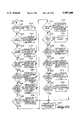
- FIG. 1is an isometric view of the control system installed with a conventional desk telephone.
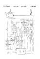
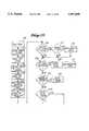
- FIG. 2is a block diagram of the control system of FIG. 1.
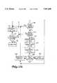
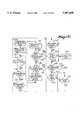
- FIGS. 3a-3iform a schematic of the control system shown in block diagram form in FIG. 2.
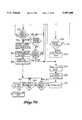
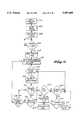
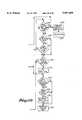
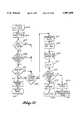
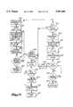
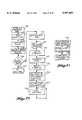
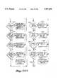
- FIGS. 4 through 38are flow charts of the software controlling the operation of the central processing unit shown in FIGS. 2 and 3.
- the control system 10is shown installed with a conventional desk telephone 12 in FIG. 1.
- the control system 10is housed in a thin rectangular box 14 having an inclined panel 16 on which are mounted several spaced apart light emitting diodes, indicated generally at 18.
- the light emitting diodes 18provide a visual indication of the operating mode or the condition of the system 10.
- the thin configuration of the box 14, coupled with its planar upper surface,provides a compact and inobtrusive base for the telephone 12.
- the control system 10is connected to the telephone 12 through a conventional multilead conductor 20 and it is connected to a conventional telephone line through a similar multilead conductor 22. Power is supplied to the control system 10 through a conventional AC cord 24 and plug 26.
- the control system 10may be connected to any telephone line which encompasses a tip and ring type pair whether in a subscriber loop or trunk.
- FIG. 2A block diagram of the control system 10 is illustrated in FIG. 2.
- the multiconductor line 22(FIG. 1) is connected to a telephone line 22 shown in the upper left hand corner of FIG. 2 while the multiconductor line 20 (FIG. 1) connected to the telephone 12 is shown at the upper right hand corner of FIG. 2.
- the telephone line 22is connected to the station line 20 through a line current detector 30 and a relay 32.
- the relay 32is controlled by a central directly to the telephone line 22 through the line current detector 30 or to other portions of the circuitry.
- the line current detector 30measures the telephone line current in order to determine the status of the telephone line. When the line current is above a predetermined value, the line current detector 30 outputs a bit to an I/O port of the central processing unit 34.
- a ring detector 33also connected across the tip and ring lines of the telephone line detects a high voltage ring signal on those lines and outputs a logic level to an I/O port of the CPU 34. As explained in greater detail below, when a ringing signal is detected by the ring detector 33, the CPU 34 outputs a logic level from an I/O port to an off hook relay 36 that lowers the impedance between the tip and ring lines of the telephone line in order to simulate an off hook condition. Signals on the tip and ring lines are coupled to other portions of the circuitry through the off hook relay 36 and conventional audio transformer 38. These signals are received from either an external source through the telephone line 22 or through the station line 20 from the telephone 12 (FIG. 1) connected to the control system 10.
- the audio signals at the output of the transformer 38are applied to a low pass filter 40 and then to both a dual-tone multifrequency detector 42 and a band pass filter 44
- the dual-tone multifrequency detector 42decodes conventional dual tone multifrequency (DTMF) signals generated either externally or by the telephone 12.
- the detector 42outputs a four bit code indicating the one of sixteen possible tone combinations corresponding to the numbers 0-9,* #, and keys A-D on some tone pads.
- the band pass filter 44is centered at about 400 Hz in order to pass various supervisory tones such as busy signals
- the output of the band pass filter 44is applied to a Schmitt trigger 46 whose output is applied to an I/O port of the CPU 34.
- the above descriptiondeals with circuitry receiving signals from an external station through the telephone line 22 or the local station 12 through the station lines 20.
- the control system 10is also capable of applying dial pulses, dual-tone multifrequency tones and supervisory tones to the telephone lines 22, or station lines 20.
- an I/O port of the CPU 34is applied to a dial pulse generator 50 which intermittently de-energizes the off-hook relay 36 in order to momentarily raise the impedence of the telephone lines 22 to simulate dial pulses
- Four bits of the data bus of the CPU 34are applied to a dual-tone multifrequency tone generator 52 which selectively generates combinations of dual tones to indicate one of 16 keys of a conventional key pad.
- the output of the dual tone multifrequency generator 52is applied to the transformer 38 through an amplifier and filter 54.
- the control system 10also includes circuitry for interfacing with the local telephone 12. Accordingly, an I/O port of the CPU 34 is applied to the input of a local tone and current generator 60 that generates supervisory tones, such as busy signals, ringing signals, etc., and loop current for the telephone station 12.
- a local current detector 62measures the current through the tip and ring lines 20 of the station. When the loop current rises above a predetermined value, the local current detector 62 generates an output to an I/O port of the CPU 34 to indicate an off-hook condition of the telephone station 12.
- the operation of the control system 10can be divided into groups of local operating modes and external operating modes.
- the control system 10is accessed through the local telephone 12 connected to the control system 10 through the station tip and ring lines 20.
- the local operating modesare as follows:
- the telephone lines 22are disconnected from the station 12 by energizing the relay 32.
- a dial toneis then applied to the local telephone station 12 by the local tone and current generator 60.
- the output of the dual tone multifrequency detector (DTMF) 42 and the output of the local current detector 62are then monitored by the CPU 34 to detect dialing tones or dial pulses, respectively.
- the CPU 34decodes the digits being dialed by the telephone station 12 and records these digits. If the CPU 34 determines that the station 12 is placing an outside call rather than programming the control system 10 or using the intercom function, the CPU 34 dials the recorded digits through either the dial pulse generator 50 or dual-tone multifrequency generator 52.
- the CPU 34When the CPU 34 has dialed the number of digits previously dialed by the local station 12 (i.e., the CPU 34 has "caught up” to the local station 12), the CPU 34 energizes the relay 32 to connect the telephone station tip and ring lines 20 directly to the tip and ring lines 22. Thereafter, the dial pulses or dial tones are applied by the local station 12 directly to the trunk tip and ring lines 22.
- the primary advantage of this "catch up" featureis the speed at which an outside number can be dialed. Conventional systems record the entire number being dialed, determine whether the number being dialed is for placing an outside call, and then apply all of the recorded numbers to the telephone lines 22.
- the "catch up" feature described aboveis particularly advantageous when placing a call through a private telephone service requiring a multidigit (usually seven) access code.
- a multidigit (usually seven) access codeIn conventional telephone systems, one must dial the access code, wait for a dial tone, then dial a multidigit station identifier and finally the seven digit telephone number.
- the access code digits, identifier digits, and telephone number digitsare sequentially dialed without waiting for dial and other supervisory tones.
- the control system 10records all of these numbers as they are dialed by the local station 12 and applies them to the telephone lines 22 in an appropriate manner.
- control system 10applies the access code digits to the telephone line, waits for a dial tone, then dials the multidigit identifier and then finally dials the seven digit telephone number. If, at any time, the control system catches up to the digits as they are being dialed by the local station 12, the CPU 34 de-energizes the relay 32 and the digits are thereafter applied to the telephone lines 22 directly from the local station.
- This "catch up” featurecan also be used when the access code is dialed from memory
- a seven digit access codemay be dialed from a memory location by dialing a selected digit such as "1.”
- the callerneed not wait for a supervisory tone confirming that the access code has been accepted Instead, the caller can dial the desired number immediately after dialing "1".
- the systemwill record the digits of the telephone number while the access code is being automatically dialed.
- the systemAfter the supervisory tone confirming acceptance of the access code is received, the system automatically dials the recorded digits of the phone number and thereafter dials any remaining digits in realtime as they are manually dialed It will also be understood that the telephone number may be dialed from memory instead of being dialed manually
- the "catch up” featurethus allows long distance telephone numbers to be dialed through a variety of long distance services in the conventional manner (i.e., "1+area code+number").
- the digits for each called numberare decoded by either the dual-tone multifrequency detector 42 or by the CPU 34 from the output of the local current detector 62 and stored in memory. This number may be repeatedly redialed by pushing appropriate keys on the local station 12 The tones corresponding to these keys are decoded by the dual-tone multifrequency detector 42.
- the CPU 34then applies dial pulses or dial tones from the dial pulse generator 50 or dual-tone multifrequency generator 52, respectively, corresponding to the memorized numbers directly to the telephone lines 22.
- the CPU 34then energizes relay 32 to apply the local station 12 directly to the lines 22.
- a busy or unanswered linecan be repeatedly called at predetermined intervals. After a call has been placed and the called station is either busy or unanswered, the automatic call back mode is selected. Thereafter, the CPU 34 will apply the dial pulses through dial pulse generator 50 or dialing tones through dual-tone multifrequency generator 52 corresponding to the previously called number. When and if the called party answers, the ringing or busy signal will cease, and this condition will be detected by Schmitt trigger 46, the output of which is applied to the CPU 34. The CPU 34 then causes tone generator 60 to generate a ring signal that is applied to the local station 12. When the local station 12 goes off hook, the off hook condition is detected by the local current detector 62 thereby causing the CPU 34 to energize the relay 32 and connect the local station 12 to the called party.
- Local stations 12are prevented from gaining access to the telephone lines 22 for any telephone number beginning with a "1" or "0" digit This feature is selected or overridden by dialing a four digit access code either through the local station 12 or, as explained in greater detail below, from an external station through lines 22.
- Incoming callsare placed on hold by pushing the appropriate keys on the local station 12.
- CPU 34then energizes the relay 32 and energizes the off hook relay 36 to maintain a low impedance condition on the lines 22.
- This low impedance created by the off hook relay 36simulates the local station 12 being off hook so that the local station 12 does not hang up on the calling party.
- the control system 10may be equipped with a "music on hold" feature that applies a radio station, a music synthesizer or other music to the lines 22 through the transformer 38 in the hold condition.
- the ringing pattern of the extensionscan be selected by selecting appropriate digits on the local station key pad. For example, by dialing "6 N #" all of the extensions to the local station will ring in a cadance of N rings Individuals can thus be selected by selecting a ringing pattern associated with that individual.
- the CPU 34causes the local tone and current generator 60 to place a cadance of three rings on the tip and ring line s 20 connected to the extensions of the local station 12.
- the local intercom modecan also be used while an external call is placed on hold.
- the appropriate keys on the local station 12are pushed, causing CPU 34 to energize relay 32 and off hook relay 36, thereby placing the outside call on hold, the CPU 34 then causes the local tone and current generator 60 to generate a dial tone for the local station 12.
- the local stationdials the intercom mode as described above to notify the individual corresponding to the selected cadance to pick up an extension.
- the currentis detected by local current detector 62.
- the CPU 34then de-energizes relay 32 to connect the lines 22 to the extension of the local station 12 and de-energizes the off-hook relay 38 since the low impedance on the line 22 is now provided by the station 12 being off-hook. This provides a "call transfer" function.
- Conferencing with two outside stationscan be accomplished by the control system 10 utilizing the telephone service "three-way calling" capability. Accordingly, if the CPU 34 determines that the local station 12 is attempting to conference with an outside line, the off hook relay 36 is momentarily deenergized to simulate a hook flash to the telephone service central office. The existing outside call is then placed on hold thereby freeing up the lines 22 for placing another outside call. The local station 12 then dials a third party. When the third party answers, the off hook condition is detected by the line current detector 30 thereby causing the CPU 34 to actuate the off hook relay 36 to simulate a hook flash. The hook flash then releases the original outside call from hold thereby connecting the two outside calls to each other and to the local station 12.
- telephone numbersmay be entered into memory of the CPU 34. These memorized numbers can then be selected by pressing appropriate keys on the key pad of the local station 12.
- the CPU 34then dials the memorized numbers through either the dial pulse generator 50 or dual tone multifrequency generator 52.
- An important feature of the control system 10is the ability to designate that the memorized numbers be dialed either through dial pulses or dialing tones. Additionally, one portion of a number can be dialed with dial pulses while the remainder is dialed through dialing tones. This is particularly important for private long distance telephone services which sometimes have an access code that can only be dialed through dial pulses.
- the long distance serviceis capable of handling dialing tones
- the dialing speed of the memory dialing featurecan be maximized. It is also possible to link two or more memory numbers automatically so that, for example, a long distance number can be dialed followed by a delay and then the subsequent dialing of a telephone service calling number.
- the CPU 34can be programmed to ring in a preselected manner although the calling party will hear a continuous ringing.
- the relay 32In the local limited ringing mode, after a predetermined number of rings the relay 32 is energized to disconnect the local station 12 from the lines 22. At that point, the ringing signal on the lines 22 is no longer connected to the local station thereby discontinuing the ringing. If the local station 12 goes off hook, the off hook condition is detected by the local current detector 62 which causes the CPU 34 to deenergize the relay 32 thereby connecting the local station 12 to the lines 22.
- the CPU 34may also be programmed to not allow the local station 12 to ring at all during certain periods. During the periods the CPU 34 energizes the relay 32 to disconnect the local station 12 from the trunk lines 22.
- the control system 10may be effectively disabled by entering a predetermined, two digit code from the key pad of the local station 12.
- the CPU 34then deenergizes the relay 32 permanently until an appropriate code is dialed so that the local station 12 is connected to the lines 22.
- the relay 32also connects the local station 12 to the telephone lines 22 in the event that power is lost since the lines 20 and 22 are connected to each other when the relay 32 is in the deenergized condition.
- the control systemalso operates in a number of external modes in which the control system 10 is accessed through external stations through the lines 22.
- the response of the control system 10 to incoming callsdepends upon the mode in which the control system is programmed. If no external modes have been programmed, the control system 10 operates in the control system disable mode in which the lines 22 are connected directly to the local station 12
- the external operating modesare as follows:
- the control system 10utilizes the three-way calling capability of the telephone service central office in a new and different manner to perform a simulated call forwarding.
- a simulated call forwarding modean outside call to the local station 12 is automatically routed to an external station.
- the ringing of the incoming callis detected by the ring detector 33 thereby causing the CPU 34 to energize the off hook relay 36 to answer the incoming call.
- the CPU 34then momentarily deenergizes the off hook relay 36 to flash the central office thereby placing the incoming call on temporary hold.
- the CPU 34then dials the call forwarding number either through the dial pulse generator 50 or the dual tone multifrequency generator 52.
- the CPU 34then once again momentarily deenergizes the off hook relay 36 to release the held incoming call thereby connecting the incoming call to the call forwarded station. Completion of the call is detected by the line current detector 30 which causes the CPU 34 to deenergize the off hook relay 36.
- the control system 10also allows for the use of the call transfer capability of the telephone service central office, in conjunction with the simulated call forwarding method described above If this call transfer capability is available, then the control system 10 may be set to forward calls as follows The ringing of the incoming call is detected by the ring detector 33 thereby causing CPU 34 to energize the off hook relay 36 to answer the incoming call. The CPU 34 then momentarily deenergizes the off hook relay 36 to flash the central office thereby placing the incoming call on temporary hold. The CPU 34 then dials the call forwarding number either through the dial pulse generator 50, or the dual tone multi-frequency generator 52. The CPU 34 then deenergizes the off hook relay 36, causing the phone company central office to connect the incoming call directly to the call forwarded station via the central office's call transfer service, and releasing the line of the control system 10 to handle another incoming call.
- control system 10may also generate a 2 second audible ringback tone after coming off hook to answer the call, but before dialing the forwarding number. This is designed to match the normal 2 second on, 4 second off cadence of audible ringback tone, thus giving the caller confidence that the call is progressing properly.
- the call forwarding numberis programmed or modified by first dialing a special three digit access code. This access code erases the previous call forwarding number The new call forwarding number is then dialed and stored into memory of the CPU 34.
- the call forwarding numbercan either be changed through the local station 12 or through an external station dialing the local station.
- a conventional answering machinemay be connected to the control system in order to broadcast prerecorded messages and record messages from the calling party in a conventional manner.
- any information communicating devicesuch as a voice synthesizer, tone generator or solid state voice recorder, may be used to implement this feature or any other feature described herein as using an answering machine.
- the control system 10then forwards the incoming call to an external location.
- the incoming callis answered by the answering machine.
- the current drawn by the answering machineis detected by line current detector 30 which then triggers the CPU 34.
- CPU 34then starts a timer, the duration of which has been pre-programmed to be the same length as the pre-recorded message on the answering machine.
- the CPU 34energizes the relay 32 which disconnects the answering machine and then energizes off hook relay 36.
- the CPUthen momentarily deenergizes the off hook relay 36 to place the incoming call on hold.
- the CPU 34then dials the forwarded number as described above before once again momentarily deenergizing the off hook relay 36 to release the hold on the calling party and connect it to the called station.
- the page alert modemay be used with either the answering mode, the simulated call forwarding mode or both the answering and simulated call forwarding modes together.
- an incoming callis detected by the ring detector 33 and answered by the answering machine.
- the answering machinethen broadcasts the prerecorded message and records the message left by the calling party.
- the off hook relay 36is energized to place the control system 10 on line.
- the CPU 34then dials the telephone number of an individual's pager to signal the individual that a message has been left on his answering machine. The individual then dials the local station 12 and his call is answered by the answering machine.
- the individualthen dials a three digit access code which prevents the control system 10 from initiating another Page Alert sequence, thus allowing the individual to retrieve the message left on the answering machine.
- the page alert functioncan be inhibited. This feature prevents an individual from responding to a page only to find that no message has been left on the answering machine.
- the control system 10offers a special feature for display-type pagers.
- a display-type pagerfunctions by having a caller dial a common phone number to reach a paging terminal. The paging terminal responds by generating a series of tones. The caller may then dial, in DTMF, a phone number that he wishes the user of the pager to call back. The paging system then transmits this number to the display of the pager and sounds an audible alert on the pager.
- a difficulty with this display-type paging systemhas been that each caller must be pre-instructed in the use of the paging system.
- the control system 10overcomes this difficulty as follows.
- the answering machines announcementis recorded to instruct the caller that he may dial his telephone number after the answering machines beep tone, instead of leaving a message as normal.
- the digitsare detected by DTMF detector 42 and stored by CPU 34.
- the off hook relay 36is energized to place the control system 36 on line.
- the CPU 34then dials the telephone number of the paging terminal, waits for detection of the response tone, then dials the number that was previously stored as entered by the caller.
- the off hook relay 36is then de-energized, releasing the line, so that the next call may be handled.
- the control system 10has taken the burden of dealing with the display paging terminal away from the caller, thus allowing the average, non-instructed caller to leave his telephone number for the display-type pager.
- the incoming callis detected by the CPU 34 through the ring detector 33.
- the CPU 34then energizes the off hook relay 36 to answer the incoming call.
- the off hook relay 36is then momentarily deenergized to place the incoming call on hold at the central office.
- the CPU 34dials the telephone number of the pager.
- the CPUthen momentarily deenergizes off hook relay 36 twice in succession to release the calling party from hold and to hang up on the pager.
- the CPU 34then momentarily deenergizes off hook relay 36 once more, to place the calling party on hold again.
- the CPU 34then dials the telephone number of the call forwarding number.
- the off hook relay 36is once again momentarily deenergized to simulate a hook flash thereby releasing the calling party from the hold and connecting the calling party to the call forwarding station
- dialing the pager number before dialing the call forwarding numberthe individual is alerted that a call will be forwarded for him. This feature is particularly important when the individual is in a public place such as a restaurant or movie theatre because it might otherwise be difficult to locate the individual.
- the page alert modemay be combined with the combination of the answering and simulated call forwarding mode.
- the operation in these modesis essentially as described above except that the calling party is informed by the prerecorded message on the answering machine that his call is being forwarded before the incoming call is placed on hold and the pager is dialed.
- the purpose of the call screening modeis to shield the local station 12 from all incoming calls other than those dialing a predetermined call screening code.
- incoming callsare detected by the ring detector 33 thereby causing the CPU 34 to answer the call by energizing the off hook relay 36.
- the calling partythen dials a predetermined access code. If the access code matches the authorized codes stored in the CPU 34, the local tone and current generator 60 generates a ringing signal on the local station 12.
- the relay 32is deenergized to connect the local station 12 to the calling party on the line 22.
- the off hook relay 36is then deenergized.
- the CPU 34can also be programmed to cause the local tone and current generator 60 to generate different ringing signals corresponding to different access codes.
- the ringing patternthus identifies the calling party to allow individuals at the local station to decide whether or not they wish to answer the calling party.
- the screening mode together with the simulated call forwarding modeis somewhat like the screening mode alone in that the identity of the calling party's access code determines the subsequent operation of the control system 10. However, instead of producing a predetermined ringing pattern corresponding to each access code, the screening with simulated call forwarding mode forwards the incoming call to one of several call forwarding numbers depending upon the identity of the access code.
- an incoming callis detected by the CPU 34 through the ring detector 33 and then answered by energizing the off hook relay 36. The calling party then dials the access code and the CPU 34 momentarily deenergizes the off hook relay 36 to place the calling party on hold at the central office.
- the CPU 34then dials a call forwarding number corresponding to the access code through either the dial pulse generator 50 or the dual tone multifrequency generator 52. Finally, the off hook relay 36 is once again momentarily deenergized to release the hold from the calling party and connect it to the call forwarding station.
- the possibilities for use of the screening with simulated call forwarding modeare extensive. For example, individual employees at a business enterprise may have their own individual access numbers so that they may be individually reached by callers.
- One limitation with the screening with simulated call forwarding mode used as described aboveis that individuals may not know the access code for each of the individuals that can be reached on the various call forwarding numbers.
- By adding the answering modea prerecorded message on an answering machine is broadcast after the answering machine answers the incoming call.
- the answering machineinforms the caller of the various access codes for each individual that can be reached through the call forwarding numbers.
- the calling partythen dials the access code for the selected individual and operation of the control system 10 proceeds as described above with reference to the screening and call forwarding mode.
- the remote modeallows the owner access to the control system 10 by dialing an appropriate access number. This allows the individual to change call forwarding numbers, receive messages left on the answering machine, change page numbers for the page alert modes, change call screening access codes, etc., all from an external location
- the remote modealso allows different modes to be selected from an external location.
- the remote modeis accessed by dialing the local station and then dialing the predetermined access number.
- the "money saver” modeis an offshoot from the remote mode. Basically, the money saver mode allows an individual to place telephone calls from an external location, such as a telephone booth, through the local station.
- One of the advantages of this modeis the ability to make long distance calls from telephone booths at the direct dial rate rather than the substantially more expensive operater assisted rate required for long distance telephone calls from telephone booths.
- the local stationis dialed and the special access number is then entered.
- the CPU 34maintains the off hook relay 36 in an energized condition while the calling station dials the desired local or long distance number. The CPU then momentarily deenergizes the off hook relay 36 to simulate a hook flash thereby placing the calling station on hold at the central office.
- the CPUthen dials the desired local or long distance number and once again momentarily deenergizes the off hook relay 36, causing the central office three-way calling service to connect the incoming call to the outgoing call.
- the callermay terminate this first call by dialing a terminate command. This causes the CPU to again momentarily deenergize off hook relay 36, thereby causing the central office to disconnect the other party.
- the callermay then dial another number if he wishes, and repeat this process as many times as desired without hanging up.
- the "Money Saver" modealso may be used in conjunction with the central office call transfer service, if available.
- This modefunctions as follows. The local station is dialed and the special access number is then entered.
- the CPU 34maintains the off hook relay 36 in an energized condition while the calling station dials the desired local or long distance number.
- the CPUthen momentarily deenergizes the off hook relay 36 to simulate a hook flash thereby placing the calling station on hold at the central office.
- the CPUthen dials the desired local or long distance number and then deenergizes the off hook relay 36, causing the central office to connect the caller directly to the desired number via the central office's call transfer service, and thereby releasing the line of the control system 10 so that the next call may be handled.
- the control system 10employs several methods to this end. First, detection of dial tone or other supervisory signals such as busy or reorder for a predetermined time may trigger a disconnect. Second, detection of silence for a pre-determined period of time may trigger a disconnect. Third, detection of an interruption in line-current may trigger a disconnect, after the expiration of a delay designed to allow the caller time to enter a command to prevent the control system from disconnecting.
- control systemmay be set to ignore the first interruption in line current that occurs with each call it dials. This handles the case where a line current interruption occurs when the third party answers in a three-way call. Therefore, the control system ignores the interruption that occurs when the called party answers, but accepts the interruption that occurs when either party hangs up.
- the control systemalso employs a feature that allows the "money saver" mode to be used on a line that has central office call waiting service.
- the call waiting service of the central officeproduces a "beep" on the line if a new call is coming in while an original call is in progress.
- One of the parties in the original callmay be placed on central office hold, while the other party speaks to the new caller.
- the control systemhandles this service as follows.
- An original callermay dial a second party via the control system's "money saver" feature. If, while the original caller and second party are conversing, a third party calls in attempting to use the control system, the control system will detect the call waiting signal and proceed as follows.
- the control systemwill generate a hook flash, causing the central office to place the original caller and second party on hold, allowing their conversation to continue, while connecting the new third party directly to the control system.
- the control systemwill then generate an audible busy indication to the new third party signifying the line is in use.
- the control systemwill hang up and wait for a ring-back from the central office indicating the original and second parties are still on central office hold.
- the control systemUpon detection of the ring-back, the control system will come off hook, thus taking the original party and second party off of the central office hold, reconnecting them to the control system, and restoring conditions to as they were before the call waiting signal was detected. In this way the original and second party's conversation was not interrupted yet the new third party was informed of the busy condition of the line.
- One useful feature of the control system 10is the ability to maintain an accurate and up-to-date customer list in order to provide customers with software updates resulting from newly developed features or modifications to telephone service operating parameters.
- Customer listsare often obtained from warranty cards which purchasers are required to return to the manufacturer to validate the warranty.
- the primary disadvantage of customer lists obtained in this manneris the failure of many purchasers to return the warranty card.
- the CPU 34is programmed to be inoperative until the purchaser enters his telephone number through the local station 12. Thereafter, software in the CPU 34 automatically dials the toll free number of the manufacturer and reads out the phone number of the purchaser and the serial number of the purchased unit which has also been stored in the CPU 34. This allows the manufacturer of the control system 10 to keep an accurate customer list for the sale of updated software.
- control system 10may be equipped with all or only some of the above described operating features It is also apparent that other operating features may be devised which are either similar or quite different from the above described operating features Operating features can be changed at any time by merely reprogramming the CPU 34.
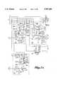
- the CPU 34includes a conventional microprocessor 70 driven by a conventional oscillator circuit 72 consisting of an inverter 74 having resistor 76 and the series combination of resistors 78 and crystal 80 connected in parallel from the output of inverter 74 to its input. Capacitors 82, 84, are connected from respective leads of the crystal 80 to ground. The shape of the waveform at the output of inverter 74 is restored to a clean square wave by inverter 86 before driving the microprocessor 70.
- the microprocessor 70includes "power up" circuitry 90 that resets the microprocessor 70 and other portions of the CPU 34 when power is initially applied to the system and interrupts the operation of the microprocessor 70 as power is lost from the system.
- the +5 volt output from power supply 92is immediately applied through resistor 94 to the RES input of the microprocessor 70.
- the +5 volt output of the power supply 92is also applied through resistor 96 to the input of inverter 98. However, the input to inverter 98 is held low by capacitor 100 until capacitor 100 has charged through resistor 96.
- inverter 98when power is initially applied to the system the input to inverter 98 is held low so that inverter 98 applies a high through resistor 102 to the base of transistor 104. Transistor 104 then saturates causing the RESET input to microprocessor 70 to go low thereby resetting the microprocessor 70. Thus, as soon as the inverter 98 and transistor 104 receive power, the microprocessor 70 is reset by a low at the collector of transistor 104. After capacitor 100 charges through resistor 96 to the switch point of inverter 98, the output of inverter 98 goes low thereby allowing the base of transistor 104 to be held low through resistor 106.
- Transistor 104is then cut off so that +5 volts is applied through resistor 94 to the RESET input of microprocessor 70. As explained in greater detail below, the power on reset is also applied to other portions of the CPU 34 as well as other circuitry in the control system 10.
- the +24 volt output of the power supply 92is applied to the cathode of Zener diode 110.
- the reverse biased voltage of Zener diode 110is a fairly large percentage of +24 volts so that as the 24 volt output of the power supply 92 starts to fall, the voltage across resistor 112 quickly falls to 0 volts.
- a voltage larger than about 0.7 voltsis applied to the base of transistor 114 through resistor 116 thereby maintaining transistor 114 at saturation.
- This interrupt subroutineterminates operation of the CPU in an orderly manner in order to prevent spurious data from being written into random access memory (RAM) as explained below
- RAMrandom access memory
- the power up circuitry 90immediately resets the microprocessor 70 other portions of the CPU 34 and other circuitry in the control system 10 as soon as AC power is applied to the power supply 92.
- the power up circuitry 90immediately causes the microprocessor 70 to execute a power down interrupt subroutine and, after a short delay, resets the microprocessor 70 as well as the other circuitry in the control system that is reset upon power up of the power supply 92.
- the microprocessor 70operates in accordance with a program of instructions stored in a read only memory (ROM) 140
- ROM 140outputs the instructions on the B0-B7 bits of an address data bus (AD BUS) from a memory location designated by the. A0-A12 address inputs.
- AD BUSaddress data bus
- the A8-A12 bits of the addressare provided by the A8-A12 bits of the microprocessor's address bus
- the address data bus B0-B7is used as both a low order address bus and a data bus
- the A0-A7 bits of the addressare written into an address latch 142 from the AD BUS
- the microprocessor 70initially places the A0-A7 bits of the instructions address on the AD BUS and then outputs a high on its address strobe (AS) output to latch the data on the AD BUS into the address latch 142.
- ASaddress strobe
- the address latch 142then applies the A0-A7 address bits to the ROM 140 while the A8-A12 address bits are applied to the ROM 140 directly to the microprocessor 70.
- a low applied to the output enable (OE) input of the ROM 140then outputs the instruction on the AD BUS and is read by the microprocessor 70.
- the CPU 34also includes a random access memory (RAM) 144 that is addressed in substantially the same manner as the ROM 140.
- RAMrandom access memory
- a signal applied to its read (W) inputdesignates the function of the RAM 144.
- the read control signalis generated as explained below Basically, a high applied to the W input causes the RAM to output data while a low applied to the W input causes the RAM 144 to input data. In either case, the RAM 144 is enabled by a low applied to its chip select (CS) input which is generated as explained below.
- CSchip select
- the ROM 140 and RAM 144are separately enabled by signals applied to their OE and CS inputs, respectively. These signals are generated by a decoding circuit from the A10-A12 address bits, R/W, data strobe (DS), and PA4 outputs of the microprocessor 70.
- the A11 and A12 address bits of the microprocessor 70are applied to NOR-gate 150 which outputs a high in the event that both address bits are low.
- the output of NOR-gate 150is applied to one input of NAND-gate 152 along with the A10 address bit of the microprocessor 70 The output of NAND-gate 152 will thus be low when the high order address bits are "100".
- This low at the output of NAND-gate 152is applied to one input of NOR-gate 154 while the other input from NOR-gate 154 is connected to the PA4 output of microprocessor 70 and a manual program switch 157. Assuming that the PA4 output of microprocessor 70 is low, then independent of the state of the program switch, the output of NOR-gate 154 will be high whenever the high order address bits are "100.” The high at the output of NOR-gate 154 enables NAND-gate 156 so that when a high data strobe pulse is output by the microprocessor 70, a low at the output of NAND-gate 156 generates a high at the output of inverter 158.
- a "program" switch 157is also connected to the PA4 I/O port of microprocessor 70 through resistor 170.
- the PA4 portis periodically tested to detect a low caused by closing switch 157 to switch the system 10 to the programming mode.
- the PA4 I/O portthus serves as an input from switch 157 and as an output to NOR-gate 154.
- NAND-gate 172is enabled to gate the R/W output of microprocessor 70 from inverter 174 to the read (W) input to RAM 144.
- the RAM 144will output data on the B0-B3 bits of the AD BUS. If the R/W output of microprocessor is low, data on the B0-B3 bits of the AB BUS will be written into RAM 144 when the RAM 144 is enabled.
- RAM 144is enabled only when the output of inverter 158 is high.
- a high at the output of inverter 158can cause transistor 160 to draw sufficient current through resistor 164 to enable RAM 144 only if transistor 180 is saturated by a high applied through resistor 182 from the RESET input to microprocessor 70.
- transistor 160 and transistor 180, and their associated circuitryfunction as a NAND-gate so that RAM 144 can be enabled only when microprocessor 70 is not being reset and the high order address bits are "100" during a data strobe.
- NOR-gate 154In the event that the high order address bits are not "100,” the output of NOR-gate 154 is low. This low at the output of NOR-gate 154 is applied to one input of NOR-gate 190. Assuming that the R/W output of microprocessor 70 is high, the output of NOR-gate 190 will be high, thereby enabling NAND-gate 192. A data strobe pulse from the DS output of microprocessor 70 will then cause NAND-gate 192 to enable the output of ROM 140. ROM 140 is thus enabled by the data strobe pulse whenever the microprocessor 70 outputs a high on the R/W output and the high order address bits are not "100.”
- the remaining circuitry in the CPU 34decodes the high order address bits and the R/W output of the microprocessor 70 to provide an enable signal for the dual-tone multifrequency detector 42. Accordingly, the output of NAND-gate 156 and the output of inverter 174 are applied to NOR-gate 200. Both inputs to NOR-gate 200 are low to produce a high that enables the dual-tone multifrequency detector 42 whenever the microprocessor 70 is designating a read function by a high R/W output and the high order address bits are "100" during a data strobe pulse. Thus, when the microprocessor 70 is designating a read function, RAM 144 and dual-tone multifrequency detector 42 are simultaneously enabled. The output of RAM 144 is on the B0-B3 bits of the AD BUS and the four outputs from the dual-tone multifrequency detector 42 are on the B4-B7 bits of the AD BUS.
- the ring detector 33includes a monolithic ring detector circuit 210 having an external filter capacitor 212.
- the AC inputs to the monolithic ring detector circuit 212are connected across the tip and ring lines of the telephone line 22 through resistor 214 and capacitor 216 which together implement a high pass filter.
- DC currentflows through resistor 218 and light emitting diode (LED) 220.
- LEDlight emitting diode
- Light emitting diode 220is optically coupled to phototransistor 222 so that when LED 220 is illuminated, sufficient current is pulled through resistor 224 to apply a low to the PA7 input of microprocessor 70.
- the PA7 inputis thus a ring detect signal that is low whenever a ringing signal is present on the telephone lines 22.
- a pair of back-to-back Zener diodes 226for limiting the voltage across the tip and ring lines and a capacitor 228 for filtering very high frequency transients.
- the line current detector 30provides a line current detect signal responsive to the telephone line current exceeding a predetermined value. It also detects dial pulses on the telephone line. Line current is detected by a pair of light emitting diodes 230, 232 connected in series with resistor 234 and the tip line of the telephone 222. When the current flowing through the telephone tip line is below a predetermined value, relatively little illumination is emitted by the light emitting diodes 230, 232. However, as the telephone line current increases, the light emitting diodes 230, 232 emit sufficient light to saturate phototransistor 236 thereby drawing sufficient current through resistor 238 to generate a high at the output of inverter 240.
- This highis applied through resistor 242 to the PA1 input of microprocessor 70 to indicate to the microprocessor 70 that the telephone line current is above a predetermined value.
- Connected in series with the telephone tip line and in parallel with resistor 234 and diodes 230, 232are the parallel combination of three series diodes, indicated generally at 246, 248. The purpose of these diodes 246, 248 is to limit the current flowing through light emitting diodes 230, 232 to a value that will not damage the diodes 230, 232.
- the off hook relay 36includes a conventional double pole relay 260 having a pair of relay contacts 262, 264 and a relay coil 266.
- relay contact 264connects the tip line through dial pulse generator 50 to the ring line through transformer 38 thereby placing a relatively low impedance between the tip and ring lines.
- the impedance between the tip and ring lines in the on-hook conditionis substantially infinite.
- operation of the control system 10requires that signals on the telephone line 22 be received even when the telephone is on hook.
- the relay 260also includes a second relay contact 262 for connecting the A and A1 lines to each other in the off hook condition in the event that multiple stations are connected to the same line.
- the relay 260is energized by saturating transistor 280 thereby drawing current through the coil 266 of relay 260.
- the transistor 280is saturated by a high applied through resistor 282 from the PB0 output of the microprocessor 70.
- the PB output of microprocessor 70is thus an OFF HOOK RELAY signal that is high to place the control system in the off hook condition.
- transistor 280is cut off by a low applied to the base of transistor 280 through resistor 284.
- Diode 286is provided to dampen the reverse EMF spike generated across relay coil 266 when current therethrough abruptly terminates.
- the control system 10is capable of dialing numbers either through dial pulses or through dual tone multifrequency signals. Dial pulses are generated by momentarily increasing the impedance between the tip and ring lines.
- the dial pulse generator 50includes a single throw relay 290 having a single contact 292 operated by a relay coil 294. When the relay 290 is in the deenergized condition and the off hook relay 36 is in the off hook condition, contact 292 connects the tip line to the ring line through transformer 38. This connection is, of course, a relatively low impedance.
- the relay 290is momentarily deenergized thereby moving the relay contact 292 downwardly, connection between the tip and ring lines through the transformer 38 switches to the substantially higher impedance of the series combination of capacitor 296 and resistor 298.
- a relay 32is provided to connect the tip and ring lines 20 of the station to either the tip and ring lines of the telephone line 22 or to the control system.
- the relay circuit 32includes a dual pole doubles throw relay 310 having a pair of relay contacts 312, 314 and a relay coil 316.
- the relay 310is energized by turning on transistor 318 by a high applied to its base through resistor 320 from the PA0 output of microprocessor 70.
- the PA0 outputis thus the local power relay signal which, when high, connects the telephone station lines 20 to the control system 10.
- transistor 318When the LOCAL POWER RELAY signal is low, transistor 318 is held at cut off through resistor 322 thereby connecting the station tip and ring lines directly to the telephone tip and ring lines 22. Diode 324 is, once again, provided to dampen reverse EMF voltages generated across coil 316 when the flow of current therethrough abruptly terminates.
- the CPU 34can dial utilizing a dual-tone multifrequency generator 52.
- the dual-tone multifrequency generator 52consists of a conventional dual-tone multifrequency circuit 330 and a conventional shift register 332. Data designating a particular combination of dual-tone multifrequency dialing tones is loaded into the shift register 332 in a serial data stream applied to the A input of the shift register 332 from the PA6 output of the microprocessor 70. The data is clocked into the shift register 332 by a clock signal applied to the CLK input of the shift register of the 332 from the PB6 output of the microprocessor 70.
- the tone generator circuit 330When all eight bits of the shift register 332 have been loaded, the tone generator circuit 330 generates a dual-tone dialing signal corresponding to the output of the shift register 332.
- the dialing tone generator circuit 330is enabled whenever a reset is not being applied to the microprocessor 70.
- the shift register 332is cleared by a low applied to its CLR input whenever microprocessor 70 is being reset.
- the output of the, tone generator circuit 330is applied to an amplifier and filter 54 and the output of the amplifier and filter 54 is connected to the transformer 38.
- the amplifier and filter circuitincludes a resistor 340 connecting the input to ground to provide a predetermined load on the dual-tone multifrequency generator 52, and a high pass network formed by resister 342 and capacitor 344 connecting the input to a summing junction of amplifier 346.
- a negative feedback network of the parallel combination of capacitor 348 and resistor 350provides a low pass negative feedback network
- the high pass network of resistor 342 and capacitor 344 coupled with the low pass network of resistor 350 and capacitor 348provides the operational amplifier 346 with a broad band pass characteristic encompassing the frequency range of the tones generated by the dual tone multifrequency generator 52.
- the gain of the operational amplifier 346can be reduced by switching resistor 354 in parallel with resistor 350 by field effect transistor (FET) 356.
- FETfield effect transistor
- the lower gain of amplifier 346is used when a music on hold capability is employed Accordingly, when the gain is to be reduced, a low is generated at the PB6 output of microprocessor 70. This low allows transistor 360 to be held low through resistor 362.
- transistor 360Since transistor 360 is thus a cut off, +9 volts is applied to FET 356 through resistor 364 thereby turning on FET 356 and connecting resistor 354 in parallel with resistor 350
- transistor 360is turned on through resistors 366 and 368 to apply a low to the gate of FET 356 thereby removing resistor 354 from the feedback path across operational amplifier 346.
- Capacitor 370is provided to prevent transistor 360 from turning on by the clock signal applied to the clock input of shift register 332 which is also generated at the PB6 output of microprocessor 70.
- the output of operational amplifier 346is applied to transformer 338 through resistor 374 and capacitor 376.
- the effective impedance of the amplifier and filter 54as seen by the tip and ring lines through transformer 38, may be increased by disconnecting resistor 378 from resistor 374.
- Resistor 378is connected in parallel with resistor 374 by turning on field effect transistor (FET) 380.
- FETfield effect transistor
- transistor 390In order to detect the same amplitude of signal on the tip and ring lines on the on hook condition, the impedance of amplifier 54 must be increased. Accordingly, when the off hook relay signal is low in the on hook condition, transistor 390 is cut off through resistor 392. Since transistor 390 is at cut off, the +9 volts is applied through resistor 394 and resistor 396 to the base of transistor 398 thereby causing transistor 398 to apply a low to the gate of the FET 380. This low disconnects resistor 378 from resistor 374 thereby increasing the effective impedance of the amplifier and filter 54.
- Dual-tone multifrequency tones transmitted from an external location or from the local station 12are, as explained above, coupled across the transformer 38 in either the on hook or off hook conditions, although the amplitude of the signals will be substantially higher in the off hook condition since the primary transformer 38 is then connected almost directly across the tip and ring lines. Accordingly, back-to-back Zener diodes 440 are provided to prevent excessive voltages from being generated across the secondary of the transformer 38 in the off hook condition.
- the signals generated across the secondary of transformer 38are applied to the low pass filter 40 which consists of an operational amplifier 410 connected in voltage follower configuration with low pass filtering characteristics provided by resistor 412 and capacitors 414, 416. The output of amplifier 410 is biased at +9 volts through resistor 418.
- the output of low pass filter 40is applied through resistor 420 and field effect transistor 422 to the summing junction of operational amplifier 424.
- Resistor 426 in combination with capacitor 428sets the gain of amplifier 424 and limits the high frequency response.
- the output of operational amplifier 424is applied through capacitor 430 to the input of dual-tone multifrequency detector 42.
- a pair of back-to-back Zener diodes 432, 434prevent overvoltage signals from damaging dual-tone multifrequency detector 42.
- dual-tone multifrequency detector 42When enabled by a high at the output of NOR-gate 200 dual-tone multifrequency detector 42 outputs a four bit digital word on the B4-B7 bits of AD BUS indicative of the particular one of 16 keys on a key pad corresponding to the tones.
- Dual-tone multifrequency detector 42also signals the microprocessor 70 of the presence of a valid tone pair by placing a high on microprocessor 70's PA5 input.
- Field effect transistor 422applies the output of low pass filter 40 to amplifier 424 when the voltage on its gate is high as explained above
- a high at the PB7 output of microprocessor 70is applied through resistor 440 and resistor 442 to turn on transistor 444 thereby pulling sufficient current through resistor 446 to make the gate to FET 422 low.
- a high at the PB7 output of microprocessor 70thus disconnects the output of low pass filter 40 from the dual-tone multifrequency detector 42.
- Capacitor 448is provided to prevent the FET 422 from switching responsive to a clock signal which is also generated on the PB7 output of microprocessor 70.
- the input to operational amplifier 424also receives a signal through resistor 460 and capacitor 462. As explained in greater detail below, this signal is generated by the dual-tone multifrequency generator in the local station 12 By coupling the output of the dual-tone multifrequency dialing tones from the local station 12, the control system 10 is able to determine the telephone numbers dialed by the local station 12.
- the output of the low pass filter 40is applied to the dual-tone multifrequency detector 42 as explained above to decode dialing tones received from the telephone lines 22 and from the local station 12.
- Supervisory tonesare decoded by a band pass filter 44 and Schmitt trigger 46 as explained above with respect to FIG. 2
- the band pass filter 44includes operational amplifier 470 having its positive input biased at +9 volts Resistor capacitor network formed by resistor 472, resistor 474 and resistor 476 coupled with capacitor 478 and capacitor 480 provide operational amplifier 470 with band pass characteristics in a conventional manner
- the Schmitt trigger 46is implemented comparator 490 having positive feedback resistor 492 connected between its output and positive input to provide hysteresis. The output of comparator 490 is pulled high through pull up resistor 494.
- the output of the comparator 490is applied to the PA3 input of the microprocessor 70 and is thus the SUPERVISORY TONE DETECT signal.
- the microprocessor 70can determine the frequency and cadence of the tone and hence identify the tone.
- loop current, supervisory tones and a ringing signal for the local station 12are generated by a local tone and current generator 60
- Loop currentis generated through resistor 500 which is applied through the local station tip line 20 through diode 502
- Local station loop currentis thus through resistor 500, 502, tip line 20, the local station 12, ring line 20 and ground through relay contact 314.
- Supervisory tonesare generated at the PB2 and PB3 outputs of the microprocessor 70 and they are applied to the inverting input of operational amplifier 510 through a band pass filter network consisting of capacitors 512, 514, 516, 518 and resistors 520, 522, 524, 526
- the output of the operational amplifier 510is biased at 9 volts by the +9 volts applied to the positive input of the amplifier 510.
- the supervisory tones at the output of the operational amplifier 510are coupled to the tip line of the local station 12 through capacitor 530, resistor 532, diode 502 and the relay 310.
- the band pass filter network connected to operational amplifier 510converts the square wave outputs from the PB2 and PB3 outputs of the microprocessor 70 into corresponding sine waves.
- the local tone and current generator 60also includes a circuit for applying a ringing signal to the local station 12. +180 volt DC power is applied to the ringing circuit through resistor 540
- the fundamental frequency for the ringing circuitis output at the PB5 output of the microprocessor 70 as a 20 Hz local ring signal
- the local ring signalis applied to transistor 542 through voltage divider resistors 543, 544.
- a low at the PB5 output of the microprocessor 70turns off transistor 542 thereby cutting off transistor 545 through resistor 546 connected between the base and emitter of transistor of 544.
- the collector of transistor 544is held at ground through resistor 548, and this ground potential is applied through resistors 550, 552, to the bases of common emitter follower transistors of 545 554, 556.
- the zero potential on the emitters of transistors 545, 556is then output through resistor 558 to relay 560.
- Diodes 562, 564are provided to protect transistors 554, 556, respectively.
- a high at the PBS output of microprocessor 70turns on transistor 542 thereby drawing sufficient current through resistor 546 and 568 to turn on transistor 545.
- Transistor 545then applies substantially all of the 180 volt DC applied through resistor 540 to the bases of transistors 554, 556 The emitters of these transmitters 554, 556, then output to the relay 560 a relatively high voltage.
- capacitor 570In operation, because of the presence of capacitor 570, the bases of transistors 554, 556 do not oscillate between 0 and 180 volt DC. Instead, the filtering effect of capacitor 570 causes the bases to oscillate in a relatively smooth waveform at an average voltage between 0-180 DC.
- the waveform applied to the relay 560is thus a relatively high voltage AC sawtooth signal.
- the PB4 output of microprocessor 70is a LOCAL RING RELAY signal that, when high, turns on transistor 590 thereby drawing current through relay coil 594.
- Relay contact 596then connects the high frequency AC ringing signal to the tip line 20 through relay 310
- a low LOCAL RING RELAY signalallows transistor 590 to be biased at cut off through resistor 598 thereby terminating the flow of current through relay coil 594 and opening relay contact 596
- Diode 600is provided to protect transistor 590 from reverse EMF transients generated when current flow through the coil 594 is abruptly terminated.
- the control system 10includes a local currect detector 62 that generates an output indicative of the current between the tip and ring lines 20 of the local station 12. It will be remembered that loop current for the local station 12 is supplied through resistor 500 from the +18 volt output of power supply 92. The +18 volt output of power supply 92 is also connected to the emitter of transistor 610 while the base of transistor 610 is connected to the opposite end of resistor 500 through resistor 612 and Zener diode 614.
- transistor 610becomes forward biased thereby supplying current through resistor 616 to the base of transistor 618 Transistor 618 then turns on thereby applying a low to the PA2 input of the microprocessor 70.
- the PA2 input of the microprocessor 70is thus the LOCAL CURRENT DETECT signal.
- the local loop currentis relatively low, the voltage across resistor 500 is less than the reverse breakdown voltage of the Zener diode 614.
- Transistor 610is then held at cut off through resistor 620 thereby allowing resistor 622 to hold transistor 618 at cut off.
- a logic level of +5 voltsis then applied to the PA2 input of the microprocessor 70 through resistor 624.
- the control system 10includes a panel 16 containing a plurality of light emitting diodes 18. These light emitting diodes are connected to respective stages of a shift register 640 through respective resistors 642.
- the shift register 640is loaded in the same manner as shift register 332. Namely, serial data from the PA6 output of the microprocessor is shifted into the shift register by a clock signal at the PB6 output of the microprocessor 70.
- the shift register 640like the shift register 332, is cleared whenever a reset signal is applied to the RESET in put of the microprocessor 70.
- the light emitting diodes 18are thus selectively illuminated by shifting the proper bits into the shift register 640.
- the RAM 144retains data stored therein only for as long as it is continuously powered Therefore, power for the RAM 144 may be supplied by an internal 9-volt battery 650. However, the RAM 144 is normally powered from the +5 volt output of the power supply 92 through diode 652. When the power supply 92 is deenergized, the +9 volts from the battery 650 is dropped to approximately 5 volts by Zener diode 654 to also apply 5 volts to the DC input of RAM 144. Under these circumstances, diode 652 isolates the battery 650 from the power supply 92.
- the voltage from the battery 650is monitored by a voltage monitoring circuit.
- the battery voltageis applied across resistor 658 to the negative input of comparator 660 through resistor 662.
- a reference voltage generated from the +18 volt output of power supply 92 by voltage divider resistor 664, 668is connected to the positive input of the comparator 660.
- the output of the comparator 660floats, thereby allowing a low to be applied to the PA6 input of microprocessor 70 through resistor 670.
- the output of comparator 660goes high, and this high is applied thorugh resistor 672 to the PA6 input of the microprocessor 70.
- the microprocessor 70operates in accordance with the program of instructions stored in the read only memory (ROM) 140.
- ROMread only memory
- FIGS. 4-38A flow chart for this program is illustrated in FIGS. 4-38.
- FIG. 4An index of the software controlling the operation of the CPU 34 is illustrated in FIG. 4.
- the softwareincludes 18 main tasks that are sequentially executed. Each of these tasks is explained in respective FIGS. 5-23.
- the softwarealso includes 13 interrupt tasks that are explained in respective FIGS. 24-36. At predetermined time intervals the task jumps from a main task to one of the timer interrupt tasks and then executes the timer interrupt task.
- the softwarealso includes a hardware interrupt task illustrated in FIG. 37. Like the timer interrupt tasks, an interrupt causes the execution of a main task and causes a jump to the interrput task to occur. In the hardware task, however, the interrupt occurs because of a signal produced by the circuitry rather than at a predetermined time.
- the softwareincludes a dialing task illustrated in FIG. 38.
- the power start-up task illustrated in FIG. 5is initially executed when power is applied to the telephone control system.
- the taskis entered at 800 and the various I/O ports and registers of the microprocessor 70 (FIG. 3) are initialized at 802 in a conventional manner.
- the shift registers 332, 640 (FIG. 3)are then cleared at 804 by generating a low at the RESET output of the microprocessor 70 as explained above with reference to FIG. 3
- the random access memory 144is checked for operability This checking is accomplished by writing two bytes of known data into the RAM and them attempting to read those two bits from the RAM and checking for a match.
- the taskbranches directly to 810 where a random access memory internal to microprocessor 70 is cleared
- the power start-up taskthen checks 812 to determine if the local telephone station is off-hook This is accomplished by sampling the output of the local current detector 62 through the PA2 I/O port of the microprocessor 70 (FIG. 3). If the local telephone is off-hook, the task remains at 812.
- the interrupt timersare started at 814 so that a timer interrupt task will occur at the proper time. The task then progresses to the on-hook task at 816.
- the on-hook task illustrated in FIG. 6,performs the various functions required when the local telephone station goes on-hook.
- the I/O ports of the microprocessorare made inactive and "aborts" are disabled at 818.
- the "aborts"if enabled, cause an immediate return from an interrupt task to the on-hook task regardless of what task is being executed when the interrupt occurred
- the taskdetermines whether a "PAGE WHEN DONE" flag is set.
- the status of a "ring disable" timeris checked at 842 to determine if the timer has timed out. If so, a ringing signal is applied from the local tone and current generator 60 (FIG. 2) to the local telephone station at 844 to inform the user that calls will henceforth cause the local telephone station to ring. If the "ring disable" mode has not recently terminated, a check is made at 846 to determine if the control system is still in the ring disable mode. This check is made because a finding that the "ring disable" mode has not recently terminated could mean either that the control system is still in the "ring disable” mode or that it has been out of this mode for a substantial period of time. If the control system is not in the "ring disable” mode, the task branches to 818. If the control system is in the "ring disable” mode, the telephone station is connected to the local tone and current generator 60 at 848 by energizing relay 32.
- the off-hook task called at 840is entered at 850 as illustrated in FIG. 7.
- the abortsare immediately disabled at 852 so that an immediate return from an interrupt to the on-hook task will not occur.
- the local telephone stationis then connected to the local tone and current generator 60 at 854 as explained above and all processing flags are cleared at 856.
- a flagis then set at 858 that allows a "parser" subtask to accept valid dialing inputs as explained in greater detail below.
- the internal battery 650(FIG. 3) is then checked at 860 by examining the PA6 I/O port of the microprocessor 70.
- the microprocessor 70causes three short tones to be generated on the local telephone station at 862 before setting a "GENERATE DIAL TONE" flag at 864.
- the three short tonesalert the user to the low battery condition, so that he may install a new battery at his earliest convenience.
- the "GENERATE DIAL TONE" flagis set at 864 without generating the three short tones at 862.
- the "GENERATE DIAL TONE" flagis recognized by the local tone generation subtask as explained in more detail below with reference to FIG. 32, causing dial tone to be produced by local tone and current generator 60 and connected to local station 12 through relay 32.
- the taskdetermines at 866 if the local station is still off-hook. If not, the task branches to the on-hook task 868 and this task is then executed as explained above with reference to FIG. 6.
- the taskbranches from 866 to 870 where a determination is made whether or not there has been a user entry error. As explained below, a user entry error is detected and indicated in a "parser" subtask If there has been a user entry error, an error tone is generated at 872 and the on-hook condition of the local station is examined at 874. If the local station is not on-hook, the error tone is once again generated at 872. Otherwise, the task jumps to the on-hook task illustrated in FIG. 6 through 876.
- the taskbranches to 880 where a determination is made as to whether the user is dialing a telephone number. Once again, this determination is made in the "parser" task explained below. If the user is found to be dialing a number on the local station at 880, the task branches to a local dial task through 882. This local dial task is explained in detail below with reference to FIG. 8.
- the taskdetermines at 884 whether the user is requesting use of the intercom. Once again, a request for the intercom is indicated by the "parser" task. If the user is requesting the intercom, the program branches through 886 to a local intercom task explained below with reference to FIG. 10.
- the output of the ring detector 33(FIG. 2) is checked at 888. If a ring indicative of an incoming call is detected at 888, a conversation task is called at 890 and executed as explained below with reference to FIG. 11.
- the programdetermines at 892 if the user is programming the phone company's speed dialing numbers. If so, the off-hook relay 36 (FIG. 2) is energized at 893 to connect the control system to the telephone trunk tip and ring lines. The microprocessor then dials "74 #" or "75 #” at 894 which are decoded by the central office. The 74 # and 75 # sequence are commonly used prefixes for storing speed dialing numbers in the phone company central office. The program then calls the conversation task through 896. If the task determines at 892 that the user is not performing a programming function, the task branches to 864 where the "GENERATE DIAL TONE" flag is set as explained above.
- the local dialing task illustrated in FIG. 8is entered at 900.
- the abortsare disabled at 902 and the "AUTO RETRY" flag is checked at 904.
- the "AUTO RETRY" flagis set when the user requests that a busy or unanswered telephone number be periodically redialed. If the "AUTO,RETRY" flag has been set, the off-hook abort flag is set at 906
- the setting of the off-hook abort flagbeing detected in the interrupt tasks as explained below causes the retry attempt to terminate in the event that the local station goes off-hook. An off-hook condition terminates the retry since the user is then electing to manually dial a number rather than allowing the control system to periodically dial the busy or unanswered number. If it is determined at 904 that the auto retry flag has not been set, the on-hook abort flag is set at 908 so that the program will return to the on-hook task illustrated in FIG. 6 in the event that the local station goes on-hook.
- the local dialing taskthen checks at 910 to determine if the control system has been programmed to accept toll calls, i.e., telephone numbers beginning with a "1" or a "0". If not, the task checks at 912 to determine if the control system has been programmed to allow a single telephone number beginning with a "1" or a "0" to be dialed. If the control system has not been programmed to allow either one or more toll calls to be dialed, the program checks at 914 to determine if a toll call is being dialed and, if so, generates an error tone through the local tone and current generator 60 (FIG. 2) to inform the user that an improper number is being dialed.
- toll callsi.e., telephone numbers beginning with a "1" or a "0”. If not, the task checks at 912 to determine if the control system has been programmed to allow a single telephone number beginning with a "1" or a "0" to be dialed. If the control system has not
- the taskprogresses to 918 where the contents of the dialing buffer is checked.
- the dialing bufferstores the telephone number to be dialed and, if no number is stored in a selected location of RAM, the error tone is generated at 916. Otherwise, the local station i s connected to the local tone and current generator 60 (FIG. 2) at 920.
- the control systemcomes off-hook by energizing the off-hook relay 36 (FIG. 2) and then waits for a dial tone at 924.
- the dialing toneis detected from the Schmitt trigger 46, the dialing task is called at 926 in order to dial the selected number.
- the conversation taskis then entered through 928 to allow a conversation with the dialed number.
- the status of the "HOLD” flagis checked at 930. As explained below, the "hold” flag is set when the telephone station is on hold. If the "HOLD" flag has not been set, the off-hook task is called through 932 to place the local station off-hook. If the "HOLD" flag has been set, a hook flash is generated at 934 to inform the user that toll call restrictions prevent the user from conducting a specific conference call. Insofar as the task determined at 930 that the "HOLD" flag was set, the hold task is then entered at 936.
- the retry taskis entered at 940.
- the abort flagsare reset at 942 and a 20-second timer is started at 944
- the 20-second timerwhich is internal to the CPU 34, determines how long a busy or ringing signal is detected in the redial of a previously busy or ringing station. If 20 seconds elapse in which the called station is still busy or ringing, then a retry occurs.
- the taskdetermines whether a "BUSY" flag or a "REORDER" flag has been previously set.
- the "BUSY” flagis set when a busy signal is detected and received
- the "REORDER” flagis set when a reorder tone (also known as a trunk busy tone) is detected in the supervisory tone detection task explained below.
- the taskdetermines whether the telephone number that is being retried was previously busy or unanswered. If the number was previously unanswered, i.e., continuously ringing, the status of the "AUDIBLE RINGING" flag is checked at 950.
- the "AUDIBLE RINGING" flagis set whenever the Schmitt trigger 46 detects an an audible ringing signal on the telephone trunk lines 22.
- the taskprogresses to 952 where a determination is made as to whether the 20 second timer has expired If not, the program returns to 946 to repeat the above-described procedure. If it is determined at 950 that the "AUDIBLE RINGING" flag is set, the task progresses to 954 where the status of the "AUDIBLE RINGING" flag is again checked. If the flag is not set thereby indicating that audible ringing has terminated, the task progresses to 956. Otherwise, the status of the 20-second timer is checked at 958 and if the timer has not expired, the task loops through 954 to wait for the audible ringing determination.
- the local telephone stationgoes on-hook at 960 by de-energizing the off-hook relay 36 (FIG. 2).
- step 948if the called station was previously busy, the "AUDIBLE RINGING" flag is checked at 962. If the flag is set thereby indicating that the called station was previously busy but is now ringing, the retry is considered successful and the task progresses to 956. If the "AUDIBLE RINGING" flag has not been set, the called station is still considered to be busy, and the 20-second timer is then checked at 952.
- the taskthus connects the local station to the local tone and current generator 60 (FIG. 2) and the CPU 34 causes the local station to ring three times at 956
- the "AUDIO RETRY" flagif reset and the "MUSIC ON HOLD” flag is set so the called party is placed on hold and the local station rings.
- a 30-second timer internal to the CPU 34is then started at 968.
- the off-hook condition of the local stationis checked by monitoring the output of the local current detector 62.
- the taskchecks to see if the 30-second timer has expired at 972. The task thus remains in the 970, 972 loop until either the local station has gone off-hook or the 30-second timer expires. In the event that the local station goes off-hook during this 30-second period, the music on hold function is terminated at 974 and the conversation task is called at 976. If the local telephone station does not go off-hook during the 30-second period, the task progresses from 972 to 978 where the on-hook task is called thereby placing the local station on-hook.
- the retry taskprogresses to 960 if either the "BUSY” or “REORDER” flags have been found to be set at 946 or the 20-second timer expires in which audible ringing is still present as determined at 958.
- progression to step 960is an indication of an unsuccessful retry in which the station is still busy or is ringing but still unanswered.
- the local stationis first placed on-hook at 960 by de-energizing the off-hook relay 36 (FIG. 2).
- the "OFF-HOOK ABORT" flagis then set at 980.
- the taskdetermines how long the control system has been retrying the called station.
- a single ring signalis applied to the local station at 984, and the "AUTO RETRY" flag is cleared at 986 so that additional retries are not attempted.
- the on-hook taskis then called at 978 to place the control system on-hook.
- the attempt timer statusis checked at 996 and, if the attempt timer has not expired, the task remains in a loop through 994 and 996 until either the attempt timer expires or ringing is detected In the event that the attempt timer expires before audible ringing is detected, the task calls the local dialing task at 998, to begin a new attempt.
- the local intercom taskis entered at 1,000.
- the "ABORT" flagsare reset at 1002 and a single tone is generated in the local telephone station at 1004 thereby informing the user that the local station should go on-hook.
- the taskremains in a loop at 1006 until the local station goes on-hook at which point a one minute timer is started at 1008.
- the one-minute timersets the duration of the local intercom task in which local intercomming occurs.
- the local telephone stationsare then rung by generating a ringing signal from the local tone and current generator 60 (FIG. 2) at 1010.
- the one-minute timeris then checked at 1012 and, if the timer has not expired, a 4-second timer internal to the CPU 34 is started at 1014.
- the taskdetermines if the local station is off-hook by examining the output of the local current detector 62 (FIG. 2).
- the taskchecks the output of the ring detector 33 at 1018 to determine if an incoming call is being received. If not, the 4-second timer is checked at 1020. If the 4-second timer is not expired, the task remains in a loop of steps 1016, 1018, 1020. At the expiration of the 4-second period, the task returns to 1010 where the local stations are once again rung a predetermined number of times. This loop will continuously repeat until either the expiration of the one-minute timer is detected at 112 or an incoming call is detected at 1018, at which point the on-hook task is called at 1022. The local intercom task can also exit the loop if the local station goes off-hook as detected at 1016.
- the "HOLD" flagis checked at 1024 to determine if an incoming call has been placed on hold, which commonly occurs when the local intercom feature is used to inform a user that an incoming call is designated for him. If the "HOLD" flag has been set, the "HOLD” flag is cleared at 1026 and the conversation task is called at 1028 to initiate the telephone conversation. If the "HOLD" flag has not been set, the output of the ring detector 33 is checked at 1030 and, if an incoming call is being received, the on-hook task is called at 1022. If ringing is not detected, the output of the local current detector is checked at 1032 to determine if the local station is on-hook.
- the taskremains in a loop composed of steps 1030, 1032 until either an incoming call is received or the local station goes on-hook.
- the on-hook taskis called through 1022.
- FIG. 11is a schematic of the conversation task which is entered at 1040.
- the "ABORT" flagsare initially reset at 1042.
- the local stationis then connected to the telephone trunk task, the "ABORT” flags are intially reset at 1042.
- the local stationis then connected to the telephone lines at 1044. This function is accomplished by de-energizing relay 32 by an output from the CPU 34.
- the control systemgoes on-hook by de-energizing the off-hook relay 36. At this time, the control system has effectively removed from the telephone line since the telephone lines are now connected to the local station.
- the "ON-HOOK ABORT" flagis then set at 1048.
- the taskdetermines whether the user has requested to go on hold. If so, the hold task is called through 1052. Otherwise, the task determines at 1054 whether the user is requesting an auto retry of a busy or unanswered station If the user is not requesting an auto retry, the task determines at 1056 whether the user is flashing the hook switch by examining the output of the local current detector 62. If the user is, in fact, flashing the hook switch, a two second delay is implemented at 1058. If the user had flashed because a central office CALL WAITING tone had been heard, then the flash causes the first calling station to be placed on hold at the central office and the user connected through to the second caller.
- the control unitwill detect and prevent this from occurring as explained below.
- the control unitprevents the user from obtaining central office second dial tone since the control unit itself produces a second dial tone.
- the taskchecks for a dial tone at 1060 and a hook flash is generated at 1062 to retrieve the previously held call from the central office If a dial tone is once again detected at 1064, the on-hook task is called at 1066 since the previously held call has apparently gone on-hook thereby generating a dial tone.
- the taskreturns to 1050 and repeats the above-described steps.
- the taskbranches to 1070 where the control system comes off-hook by energizing the off-hook relay 36 (FIG. 2).
- the local stationis then connected to the local tone and current generator 60 at 1072 by energizing relay 32.
- the CPU 34then causes the local tone and current generator 60 to generate a single tone at 1074 to inform the user that he should hang up
- the taskchecks at 1078 for the presence of a busy or re-order signal at the output of Schmitt trigger 46.
- the taskchecks at 1080 for an audible ringing signal and, if no such signal is detected, checks at 1082 to determine if the 20-second timer has expired. If not, the task returns to 1078. At the expiration of the 20-second timer, a check is made at 1084 to determine if the local station is off-hook If not, three rings are applied to the local stations at 1086 signifying the failure of auto-retry to detect the busy or ringing condition, and the on-hook task is called at 1066.
- a "RETRYING BUSY NUMBER” flagis set at 1088 and the "AUTO RETRY” flag is set at 1090.
- a retry timeris also set for two hours. If a ringing signal, rather than a busy or reorder signal is detected, a "RETRYING UNANSWERED NUMBER” flag is set at 1092 before the "AUTO RETRY” flag is set and the retry timer is set for two hours at 1090. The task then remains in a loop at 1094 until the local station goes on-hook at which time the retry task is called at 1096. In the event that the local station is found to be off-hook at 1084, the conversation task is recalled at 1098.
- the hold taskis entered at 1100.
- the "ABORT" flagsare reset at 1102 and the local station comes off-hook by energizing the off-hook relay 36 at 1104 thus placing the distant party on hold.
- the local stationis then connected to the telephone lines by de-energizing relay 32 at 1106.
- musical tonesare generated by the dual-tone multifrequency generator 52 and applied to the tip and ring lines of the telephone trunk and local station so that the distant party will hear music while being "on hold.”
- the hold taskcauses the user to hear a second dial tone generated by the control unit and allows the user to access the advanced features of the control unit.
- the "HOLD" flagis then set at 1110 and the "KEY STROKE PARSING" flag is set to allow dialing to occur.
- a 5-minute hold timeris started at 1112 to terminate the hold after five minutes, and a second dial tone is generated at 1114 to allow the user to dial a third party for conference calls or access other advanced features.
- the 5-minute hold timeris then checked at 1116 and if the hold timer has expired, the on-hook task is called at 1118.
- the hold taskchecks at 1120 to determine if there is less than one minute left before expiration of the hold timer. If so, a check is made at 1122 to determine if the local station is on-hook and, if so, a single ring is applied to the local station at 1124. These steps 1120-1124 thus remind the user that a call is being held just prior to the expiration of the hold timer.
- the hold taskthan progresses to 1126 where an on-to-off hook transition is detected thus indicating that the local station has come off hold. If this on-to-off hook transition is detected the "HOLD" flag is cleared at 128 and the conversation task is called at 1130 to once again initiate a conversation between the local station and the distant party.
- the taskdetermines at 1132 whether the user is requesting the intercom function. If so, the local intercom task is called at 1134. Otherwise, the task determines at 1136 whether the user has committed an entry error as explained in greater detail below. If an entry error has been committed, the local tone and current generator 60 generates three error beeps at 1138 and the task then progresses to 1114 as explained above. If no user entry error has been committed and the user entry has instead been successful, the task also branches to 1114 through 1138. If the user has not committed an entry error, but has nevertheless not successfully completed dialing a number, a request for user dialing is checked at 1140. If the user is not requesting dialing, the task returns to 1120.
- the music on hold functionis disabled at 1142, the "ABORT" flags are reset at 1144, a hook flash is generated at 1146 by momentarily de-energizing relay 36 in order to obtain a second dial tone from the central office and, when the second dial tone is detected at 1148, the local dialing task is called at 1150. If the local dial tone is not detected at 1148, three error beeps are generated at 1138 before progressing to 1114.
- the answer mode determination taskdetermines the operating mode used to answer incoming calls.
- the talkis entered at 1160 and the "ABORT" flags are reset and a ring counter is set to zero at 1162.
- a determinationis made at 1164 whether the local station is off-hook by sampling the output of the local current detector 62 (FIG. 2). If the local station is not off-hook, the task determines at 1166 whether the call forwarding mode has been selected. If so, the task then determines at 1168 whether the answering machine mode has been selected. If not, a selection of the page alert mode is detected at 1170 and, if the page alert mode has not been selected, the selection of the call screening mode is detected at 1172.
- the taskchecks at 1174 to determine if a ring-on cycle has been detected.
- a ring-on cycleis a predetermined ringing cadence normally generated by the central office for an incoming call.
- the ring on cycle detection stepis also performed if the call forwarding mode has not been selected, or if the call forwarding mode has been selected along with the answering machine mode. If the call forwarding mode has been selected and the page alert mode has been selected, but not the answering machine mode, the task jumps to an answer page ("ANS PAG") subtask at 1176. Finally, if the page alert mode has not been selected, and the call screening mode has not been selected, a normal forwarding mode task is called at 1178.
- the ring counteris incremented at 1180.
- the taskjumps to an answer remote ("ANS REM") subtask value at 1184.
- the answer ring countis a value programmed by the uses which allows the user to select how many rings the control system should receive before answering an incoming call. Assuming that the ring count has not yet reached the answer ring count, the task checks at 1186 to determine if the ring count is equal to the limited ring count number
- the limited ring count numberis programmed by the user to limit the number of rings of the local station in response to an incoming call.
- the local stationis connected to the local tone and current generator 60 and the local station is disconnected from the central office trunk lines at 1188 in order to prevent any more ring signals from being applied to the local station. If the ring count has not reached the ring count limit or after the local station has been disconnected from the telephone lines, a 6-second, ring-off cycle timer is started at 1190. Thereafter, a determination is made at 1192 whether the local station has gone off-hook to answer the call. If the local station has not gone off-hook, but a ring-on cycle is detected at 1194, execution of the task resume at 1164. Otherwise, the 6-second off cycle timer is checked at 1196 to determine if it has expired If so, the on-hook task is called at 1198. Otherwise, the answer mode determination task returns to 1192.
- the taskbranches to 1200 where a check is made for the answering machine mode. If the answering machine mode has not been selected, nor has the page alert mode been found to be selected at 1202, the conversation task is called at 1204 since no additional function is requested of the control system.
- the selection of the call forwarding modeis detected at 1206. If the simulated call forwarding mode has been selected, the task jumps to the answer forward ("ANS FWD") subtask at 1208. Otherwise, the page alert mode is detected at 1210 and a determination is then made at 1212 whether call screening has been selected. If not, a "PAGE WHEN DONE" flag is set at 1214 before checking for the "DISPLAY PAGER” flag at 1215. If the "DISPLAY PAGER" flag is not set, then the task waits for the end of the answering machine announcement at 1228.
- the end of announcement determinationmay be made by detecting the "BEEP" tone from the answering machine, or by expiration of a pre-programmed answering-machine-delay timer.
- the taskthen progresses to 1229, where the task idles for a predetermined amount of time while accepting and storing DTMF digits entered by the caller. These digits will be retrieved from memory later in the PAGE ALERT TASK, and transmitted to the paging terminal to appear in the display of the user's pager, thus indicating a telephone number he should call back.
- the answering machine announcementwould typically be used to instruct callers to dial their phone number. After the digits have been stored at 1229, the task progresses to 1216.
- the taskprogresses to 1216 without first setting the "PAGE WHEN DONE" flag at 1214. This routing occurs because there is no need to dial the telephone number of a pager since the page alert mode has not been selected Also, if the page alert and call screening modes have both been selected, the "PAGE WHEN DONE" flag cannot be set until a determination is made that the incoming call is one selected for answering by the call screening function.
- the remote mode detected at 1216allows the user to access the control system at a remote location as explained above. If the remote mode is selected, the local station is connected to the central office lines at 1218 by de-energizing the relay 32 The local station then comes off-hook at 1220 by energizing the off-hook relay 36 (FIG. 2). The wait for access code task is then called at 1222. In the event that the remote mode has not been selected, the task checks at 1224 to determine if the call screening mode has been selected If not, the conversation task is called at 1226. If the remote mode has not been selected, but the call screening mode has been selected, the task progresses through 1218-1222 as explained above.
- the answer mode determinations taskcalls a number of subtasks illustrated in FIG. 14.
- the answer page (“ANS PAG”) subtask called at 1176is entered at 1230.
- a determinationis first made at 1232 whether the call screening mode has been enabled and, if so, the answer "wait for access” ("ANS WAC”) subtask starting at 1234, is executed
- the local stationis connected to the trunk lines at 1236 by de-energizing relay 32 (FIG. 2), the control system comes off-hook at 1238 by energizing the off-hook relay 36 (FIG. 2), an answer tone sequence is generated at 1240 as explained below and the wait for access code task is called at 1242.
- steps 1244-1248which are identical to steps 1236-1240, respectively, are executed before a "EXIT TO NORMAL FORWARDING" task flag is set at 1250. Finally, the page alert task is called at 1252.
- the control unithas determined that an answering machine has answered the call
- An answering machine delay timeris then started at 1262 and, 1264, the off-hook relay 36 is energized to place the control system off-hook, and "FIXED TIME ABORT,” "LINE DISCONNECT ABORT,” and "SUPERVISORY TONE ABORT” flags are set.
- a determinationis made at 1266 whether a caller has entered a correct remote access code.
- a usercan dial a predetermined access code which allows the user to modify the mode of the control system, enter new call forwarding numbers, etc from a remote location If the user has entered the correct access code, the local station is connected to the local tone and current generator 60 at 1268 by energizing relay 32. The remote task is then called at 1270. If the user has not entered a correct access code, or has not entered any access code, the selection of the call screening mode is checked at 1272.
- a 30-second timer internal to the CPU 34is started at 1284. This allows the user 30 additional seconds to enter an access code after the answering machine announcement is complete.
- the presence of the correct remote access codeis then checked at 1286. If the caller has not entered the correct access code as preset by the call screening feature, the task checks at 1288 to ensure that the call screening mode was selected. If so, a check is made at 1290 to determine if the user has entered a three-digit code. If so, a determination is made at 1292 if the code is a valid call screening code. If an incorrect code has been dialed, the priority caller task is called at 1294.
- the priority caller taskis called at 1294. Finally, if the page alert mode has been selected, the priority caller task is called at 1294 after the "PAGE WHEN DONE" flag has been set at 1298.
- the above steps 1292-1298are also executed if a determination is made at 1300 that the call screening mode has been selected and the user has entered a three-digit code.
- the programIn the event that the user has not entered the correct remote access code as detected at 1286 and the call screening mode has not been selected, the program remains in a loop at 1310 until the expiration of the 30-second timer at which point the on-hook task is called at 1312.
- the answer remote ("ANS REM") subtask, called at 1184 of FIG. 13,is entered at 1320.
- the presence of the page alert modeis first checked at 1322 and, if the page alert mode has been selected, the task returns to the answer mode determination task through 1324 and 1185 of FIG. 13. If the page alert mode has not been selected, a determination is made at 1126 whether the answering machine mode has been selected. If so, the task once again exits through 1124. If neither the page alert mode nor the answering mode has been selected, the remote mode is detected at 1328 to branch to the ANS WAC subtask at 1234 through 1330. Finally, if none of the foregoing modes have been selected, the task determines at 1332 if the call screening mode has been selected and, if so, branches to 1234 through 1330 and, if not, returns to the answer mode determination task through 1324.
- the page alert taskillustrated in FIG. 15, is entered at 1340 and, as before, the "ABORT" flags are reset at 1342.
- the pager number corresponding to the telephone number of the pageris than transferred to a dialing buffer in the CPU 34 at 1344.
- the taskchecks at 1348 to determine if the "EXIT TO NORMAL FORWARDING TASK" flag has been set.
- a hook flashis generated at 1356 by momentarily de-energizing the off-hook relay 36, thus placing the calling party on central office hold.
- the three second delay at 1354is required since central office switching equipment will not generally accept a hook flash immediately after the local station comes off-hook.
- a second dial toneis normally generated at the central office. The task then waits for receipt of the dial tone at 1358. If paging is to occur without a subsequent call forwarding, the task branches from 1348 to 1360 thereby causing the control system to come off-hook by energizing the off-hook relay 36 The task then once again waits at 1358 for a dial tone.
- the dialing taskis called at 1360 in order to allow the telephone number of the pager to be called.
- the status of the "DISPLAY PAGER” flagis then checked at 1390. If the flag is not set, then the task progresses to 1362. Otherwise, if the "DISPLAY PAGER" flag is set, then the pager called must be a display type pager.
- the taskthen waits for detection of the paging terminal's beep tones at 1391. These beep tones indicate the terminal is ready to accept digits to be sent to the pager's display. The task then transfers the stored digits for the page display to the dialing buffer at 1392.
- the taskalso adds to the dialing buffer a predetermined "PAGER TERMINATING DIGIT", which is used to indicate to the paging terminal that dialing is complete.
- the contents of the dialing bufferare then dialed at 1393, and then the task progresses to 1362.
- the status of the "EXIT TO NORMAL FORWARDING TASK" flagis then checked at 1362. If the flag is set, a hook flash is generated at 1364 to conference the caller into the pager station. A pager delay timer is then started at 1366 for a period corresponding to the length of time required for the pager terminal to respond to the call. If the remote mode has been selected, as determined at 1368 a check is made at 1370 to determine whether the user has entered the correct remote access code. If not, or if the remote mode has not been selected, the task remains in a loop at 1372 and 1368 until the expiration of the pager timer. If the user has entered the correct remote access code, a hook flash is generated at 1374 to disconnect the paging terminal from the local station and the remote task is called at 1376.
- the "PAGE WHEN DONE" flagis cleared at 1378 and the status of the "EXIT TO NORMAL FORWARDING TASK" flag is checked at If the flag is set, a hook flash is generated at to disconnect the paging terminal and the presence of a dial tone is detected at 1384. If a dial tone is present, thereby indicating that the caller has already hung up, the on-hook task is called at 1386. The on-hook task is also called if the "EXIT TO NORMAL FORWARDING TASK" flag is not determined to be set at 1380. Finally, if the dial tone is not found to be present at 1384, the normal forwarding task is called at 1388.
- FIG. 16is a flow chart of the normal forwarding task which is entered at 1400.
- the "ABORT" flagsare reset at 1402 and a determination is made at 1404 whether the station is already off-hook If not, the control system goes off-hook at 1406 by energizing the off-hook relay 36 and, after a three-second delay at 1408, a determination is made at 1409 as to whether the caller has entered a remote access code. If the caller has entered a remote access code, then the unit progresses to 1438. Otherwise, an artificial audible ringback is generated at 1411. This matches the cadence of normal ringback, so the caller will remain on the line.
- the taskthen progress to 1410, where a hook flash is generated to obtain a dial tone from the local station.
- the forwarding numberis then transferred to the dialing buffer in the CPU 34 at 1412 and the task then waits for a dial tone at 1414.
- the forwarding numberis then dialed at 1416 and, after a delay of two seconds at 1418, the "CALL-TRANSFER-AFTER-FORWARDING" flag is checked at 1419. If this flag is set, then the task progresses to 1421 where the control system goes on hook and returns to ON-HOOK TASK at 1423. By going on-hook, the phone company's "CALL-TRANSFER" feature will transfer the caller directly to the forwarded number. This freezes up the control system to handle another call.
- a 60-second timeris then started at 1428 and the task checks at 1430 to determine if the remote mode has been selected This allows the user 60 seconds after the beginning of a forwarded call to enter a valid remote access code. If the remote mode has not been selected, the task waits at 1432 for the expiration of the 60-second timer. If the remote mode has been selected, a determination is made at 1434 whether the user has entered the correct remote access code.
- the taskremains in a loop composed of 1432, 1430, 1434 until the expiration of the 60-second timer at which point the task waits at for an abort.
- the "ABORT" flagsare reset at 1438.
- the local stationis connected to the local tone and current generator 60 and a hook flash is generated to disconnect the forwarded call, at 1440, and the remote task is then called at 1442.
- the wait for access code task illustrated in FIG. 17is entered at 1450.
- steps 1452-1456various "ABORT" flags are initially reset and then selectively set for use as explained below.
- a 20-second timeris then started at 1458 before the task checks at 1460 to determine if a three digit code has been entered. If not, the selection of the call screening mode is checked at 1462 and if the call screening mode has not been selected, a determination is made at 1464 as to whether the remote mode has been selected. If the three digit code has not been entered, but the call screening mode has been selected, the task determines at 1466 if the 20-second timer has expired If so, the on-hook task is called at 1468.
- the callerWhen the call screening mode is selected, the caller thus has 20 seconds to enter the correct access code. Otherwise, the wait for access code task proceeds to 1464 to check if the remote mode has been selected. If the remote mode has been selected, the task determines at 1470 whether a correct remote access code has been entered. If so, a check is made at 1472 to determine if more than 20 digits have been entered. If more than 20 digits have been entered, there is the possibility that a remote user is attempting to enter the correct remote access code by trial and error. Accordingly, if more than 20 digits have been entered, the task checks at 1474 to determine if the call screening mode has been selected. If not, the program returns to 1460 Otherwise, the priority caller task is called at 1476. If the remote access code is correctly entered and less than 20 digits have been entered, the local station is connected to the local tone and current generator 60 at 1478 and the remote task is called at 1480.
- the priority caller taskis illustrated in FIG. 18 and entered at 1500.
- the "ABORT" flagsare reset at 1502 and the local station is then connected to a local tone and current generator 60 at 1504.
- the taskchecks at 1506 to determine if the three digit call screening code previously entered is valid. If so, a determination is made at 1508 whether the control system is programmed to utilize the call screening code to forward the calling party to a call forwarding number. It will be recalled that a call screening code can be used to either forward the calling party to an external station or to cause the local station to ring. If the screening code is used to forward the call, the screened forwarding task is called at 1510. Otherwise, the mode status is checked for the page alert mode at 1512.
- a "EXIT TO NORMAL FORWARDING TASK" flagis set at 1516 and the page alert task is called at 1518 in order to dial the telephone pager and then forward the incoming call to an external location after the pager has been dialed.
- the priority caller taskbranches to 1520 where a 30-second timer is started.
- the 30-second timeris also started if the call screening code dialed in the incomming call is not valid.
- audible ringingis provided to the caller so that the caller will not know that his code is invalid and merely assumes that the called party is not available so that the ringing continues indefinitely.
- the taskremains in a loop at 1522 and 1524 until the 30-second timer expires at which point the on-hook task is called at 1526.
- the taskprogresses through 1508 to 1512 and, if the page alert mode has not been selected, the determination is made at 1530 whether the simulated call forwarding mode has been selected If so, the normal forwarding task is called at 1532. Otherwise, a 30-second timer is started at 1534 and a determination is made at 1536 whether the user has designated the local phones to ring normally. If so, the local station rings in a cadence of two seconds on and four seconds off at 1538, and audible ringing is provided to the caller at 1540.
- the local stationrings a number of times as determined by the call screening code at 1542 while providing audible ringing feedback to the caller at 1540.
- the taskthen checks at 1544 for the local station going off-hook when the user answers the local station. When the local station is answered, the conversation task is called at 1546. If the local station does not go off-hook, a check of the 30-second timer is made at 1548. The task returns to 1536 until the expiration of the 30-second timer at which point the on-hook task is called at 1550.
- the remote task illustrated in FIG. 19is entered at 1560.
- the remote taskis executed when the user calls in from a remote location and correctely dials his remote access number.
- the "ABORT” flagsare reset at 1562 and the "PARSING OF USER KEYSTROKES” flag is set at 1564.
- the "FIXED TIME ABORT” flag and “LINE DISCONNECT ABORT” flagare set at 1566 and the "SUPERVISORY TONES ABORT” flag is set at 1568.
- a remote success toneis generated to let the user know that his remote access code has been accepted and he may now enter a command.
- the taskbranches to 1570 where a remote success tone is once again generated. If the user has not completed the key sequence, the task checks at 1588 to determine if there is an error in keying the data. If not, the task returns to 1572 and executes the steps as explained above If an error has occurred, an error tone is generated at 1590 and a determination is made at 1592 as to whether the user is pressing the "*" key to cancel the error tone and attempt to properly enter the data.
- the remote dial taskentered at 1600, is illustrated in FIG. 20.
- This taskis used to dial a third party through the local station from a remote location.
- the "ABORT" flagsare initially reset at 1602 and a determination is then made at 1604 as to whether unlimited toll calls are allowed If so, the status of the dialing buffer is checked at 1606 to determine if the buffer contains the number to be dialed. Otherwise, a check is made at 1608 to determine if a single toll call is allowed. If so, the dialing buffer is once again checked at 1606. If toll calls are not permitted, the task checks at 1610 to determine if the number to be dialed begins with "0" or a "1".
- an unauthorized numberis being dialed and an error tone is thus generated at 1612 before the remote task is called at 1614. If the first digit of the number being called does not begin with a "0" or a "1”, the contents of the dialing buffer is checked at 1606. If the buffer is empty, thus indicating that a call is being attempted but a telephone number has not been loaded into the dialing buffer, the error tone is generated at 1612 and the remote task is then called at 1614.
- a hook flashis generated at 1616 to place the calling party on hold and to obtain a dial tone for the control system.
- the control systemwaits at 1618 for receipt of the dial tone and then calls the dialing task at 1620 to dial the number contained in the dialing buffer.
- the control systemthen generates a predetermined delay at 1619, and then checks the status of the "CALL-TRANSFER-AFTER-MONEY-SAVER" flag at 1621. If this flag is set, then the control system goes on hook at 1623 and returns to ON-HOOK task at 1625. This signals the phone company's CALL TRANSFER service to transfer the caller directly to the number dialed, thus freeing up the control system to handle another call. This dramatically increases the number of calls that can be handled by the control system.
- the remote three-way conversation taskis illustrated in FIG. 21.
- the taskis entered at 1630 and the "ABORT” flags are reset at 1632.
- the "SUPERVISORY TONE ABORT” flag, "FIXED-TIME-ABORT” flag, and "LINE-DISCONNECT-ABORT” flagis then set at 1634 and the "REMOTE THREE-WAY-CALLING” flag is set at 1636 for use by the remote intercom task as explained below.
- the "PARSING OF KEYSTROKES” flagis set at 1638 and a check is made at 1640 to determine if the user is requesting the remote intercom feature. If so, the remote intercom task is called at 1642.
- This CALL WAITING signalis normally a short "beep" tone with an interruption in line current before and after the beep. The two line current interruptions within a short period of time are thus detected by the control system as a CALL WAITING signal.
- the control systemUpon detection of this CALL WAITING signal at 1641, the control system generates a flash at 1655, thus signalling the phone company to place the original parties on the phone company hold, allowing their conversation to continue, and connect the control system to the new "CALL WAITING" party.
- the control systemthen generates a busy signal to the new party signifying that the control system is busy and that the new party should hang up and call back later.
- the control systemthen goes on hook at 1657 and starts a 5 second timer at 1658.
- the taskthen enters a loop, waiting for ring detection at 1645 or expiration of the 5 second timer at 1647. If the original 2 parties placed on hold at the phone company are still there, then the phone company will ring the line, and the ring will be detected at 1645 causing the control system to come off hook at 1643 and then progress to 1644. If the original 2 parties had finished talking, then no ring signal will be generated by the phone company, and the 5 second timer will expire at 1647, causing the control system to enter the ON-HOOK-TASK at 1649.
- the taskIf the user is requesting the three-way conference call be canceled, the task generates a hook flash at 1646.
- the hook flashdisconnects the third party.
- a determinationis then made at 1648 whether a dial tone has been detected If not, the "REMOTE THREE-WAY CALL" flag is cleared at 1650 and the remote task is then called at 1652. If a dial tone is detected at 1648, one of the parties to the previous three-way conversation must have gone on-hook. As a result, the dial tone is eliminated at 1654 by generating a hook flash.
- FIG. 22illustrates the remote intercom task which is entered at 1660
- the "ABORT" flagsare first reset at 1662 and the local station is connected to the local tone and current generator 60 at 1664.
- a ring signalis applied to the local station telephones at 1668 with the number of rings being determined by the ringing code dialed by the user as explained above.
- Audible ringingis then provided to the user at 1670 and a 4-second timer is started at 1672.
- the status of the one-minute timeris then checked at 1674 and, if the timer has not expired, a check is made at 1676 to determine if the local station is off-hook If the local station is not off-hook, a check is made at 1678 to determine if the user has cancelled the intercom request. If not, the status of the 4-second timer is checked at 1680. If the 4-second timer has not expired, the task returns to 1674 to check the status of the one-minute timer. If the 4-second timer has expired, execution of the task resumes at 1668. Thus, the user calling from a remote location may cancel the remote intercom during each four second interval between rings.
- the local stationis connected to the telephone lines at 1682 by de-energizing the relay 32 (FIG. 2).
- a checkis then made at 1684 to determine if the "REMOTE THREE-WAY CALL" flag is set. If the flag is not set, the remote task is called at 1686 Otherwise, the remote three-way conversation task is called at 1688 since the user had been in a conference call with a third party from a remote location.
- the screened forwarding task illustrated in FIG. 23is entered at 1700.
- the screen forwarding taskcauses an incoming call to be forwarded to one of several numbers depending upon the call screening code dialed by the caller.
- the "ABORT" flagsare reset at 1702 and a hook flash is generated at 1704 to obtain a dial tone from the central office and put the calling party on hold.
- the call forwarding telephone number corresponding to the call screening code dialed by the calling partyis then transferred to the dialing buffer at 1706. If no telephone number was in the portion of memory designated by the call screening code, the dialing buffer will now be empty and this fact is recognized at 1708 to call the on-hook task at 1710.
- the taskwill wait at 1712 for a dial tone allowing the control system to dial the call forwarding number which is accomplished by calling the dialing task at 1714.
- a second hook flashis generated at 1718 to connect the calling party to the call forwarding number.
- the "FIXED TIME ABORT" flag and "LINE DISCONNECT ABORT” flagare set at 1722 and the "SUPERVISORY TONE ABORT” flag is set at 1724.
- the taskthen remains in a loop at 1726 waiting for an abort resulting from a dial tone (for five seconds), a busy signal (for sixty seconds), a ringing signal (for sixty seconds), a line disconnect if the call forwarding station goes on-hook or a fixed time abort (30 minutes).
- a dial tonefor five seconds
- a busy signalfor sixty seconds
- a ringing signalfor sixty seconds
- a line disconnectif the call forwarding station goes on-hook or a fixed time abort (30 minutes).
- the on-hook taskis immediately called.
- the previously described-flow chartsare for the main tasks that are executed either upon power up or upon being called by another main task.
- a number of interrupt subtasksare executed at fixed intervals upon the occurrence of an interrupt.
- the first of these subtasksis the 500 microsecond timer interrupt service task which is illustrated in FIG. 24 and entered at 1730.
- the timer interrupt service taskstarts a countdown timer internal to the CPU 34 for 500 microseconds at 1732.
- the supervisory tone detection subtaskis called at 1734.
- the supervisory tone detection subtaskis executed every 500 microseconds when the timer interrupt occurs.
- the supervisory tone detection subtaskis illustrated in FIG. 25 and entered at 1736.
- the supervisory tone detection subtaskcounts the transitions at the output of the Schmitt trigger (FIG. 2) during several sample periods in order to determine if a busy, dial tone, or audible ringing is present on the trunk lines.
- the taskchecks at 1738 to determine if transitions are present on the Schmitt trigger output. For each transition detected, a transition counter is incremented at 1740. At the expiration of the sample period, as detected at 1742, the transition counter is cleared and the sample timer is restarted at 1744. The status of the sample timer is also checked at 1742 if transitions are not detected at the output of the Schmitt trigger at 1738.
- the taskchecks at 1758 to determine if the tone cadence matches an audible ringing. If so, a flag is set at 1760 to indicate that the tone is for an audible ringing. Otherwise, a flag is set at 1762 to indicate that the detected tone is not for audible ringing. A check is then made at 1764 to determine whether the cadence of the received signal matches the cadence and frequency of a dial tone. If so, a flag is set at 1766 to indicate that a dial tone is being detected. Otherwise, a flag is set at 1768 to indicate that the detected tone is not a dial tone.
- the line disconnect detection subtaskdetects when a line disconnect current interruption occurs when the called party goes on-hook.
- the taskis entered at 1800 and a determination is first made at 1802 as to whether the "LINE DISCONNECT ABORT" flag is set.
- the output of the line current detector(FIG. 2) is then sampled at 1804 to determine if a line current interruption indicative of the calling party going on-hook has been detected.
- a current interruptioncan also occur when the central office signals that a call is waiting for the local station.
- a call waiting signalis, however, a double interruption.
- the taskthus checks at 1806 to determine if the current interruption detected at 1804 is for a call waiting signal. If not, a determination is made at 1808 whether the line current interruption detected at 1804 followed a double interruption indicative of a call waiting signal.
- the line current interruption detected at 1804may have been the call waiting party going on-hook and the line current interruption detected at 1804 should thus be ignored. If the line current interruption did not just follow a double interruption, as determined at 1808, then a determination is made at 1809 as to whether the "REMOTE 3-WAY CALL" flag is set. If it is not set, then the current interruption must have resulted from the called party going on hook, and therefore the "ABORT" subtask is called at 1810.
- the "REMOTE-3-WAY CALL" flagis set, then the "MONEY-SAVER” feature is in use, and a determination is made at 1811 as to whether the "IGNORE 1st INTERRUPTION” flag is set, indicating that the phone company transmits line current interruptions when the called party answers. If so, then a determination is made at 1814 as to whether this is the first interruption. If it is, then the task progresses to the CIRCULATOR subtask at 1812, thus ignoring the first interruption.
- the taskprogresses to 1815 where the fixed-time-abort timer is reduced to 20 seconds before progressing to the CIRCULATOR subtask at 1812.
- the control systemgives the user 20 seconds to enter a new command or phone number after detecting a line current interruption due to the the other party hanging up.
- the taskthen calls the circulator subtask at 1812.
- the circulator subtaskis also called if the "LINE DISCONNECT ABORT FLAG" is not set, or there is no line current interruption.
- the circulator subtaskis entered at 1820. Basically, the circulator subtask causes various other tasks to be executed in a predetermined order and with a predetermined frequency.
- a circulator counteris incremented at 1822 and a check is made at 1824 to determine if the circulator counter is equal to five. If so, the circulator counter is reset to one at 1826. The circulator thus respectively counts from one to five. If the circulator counter is less than five, a determination is made at 1828 whether the count is equal to two. If so, the ring detection subtask is called at 1830.
- the ring detection subtaskcalled at 1830 of FIG. 27, is illustrated in FIG. 28.
- This subtaskwhich is entered at 1840, performs a debouncing function on the signal received from the ring detector (FIG. 2).
- the determinationis first made at 1842 whether ringing has been present for at least one hundred milliseconds. This prevents erroneous ring detection caused by "dial-tap.” If so, a flag is set at 1844 to indicate that a ring has been detected. If the ringing has not been present for at least one hundred milliseconds or after the flag has been set at 1844, a check is made at 1846 to determine if ringing has been absent for at least 1.5 seconds.
- the 1.5 second timingensures that the ring flag will stay set until the true end of each "ring on" cycle. If so, a flag is set at 1848 to indicate that a ring has not been detected and the shift register subtask is then called at 1850. If the ringing has not been absent for at least 1.5 seconds, the shift register subtask in immediately called. Thus, before the shift register subtask is called at 1850, the ring indication flag remains set only if ringing has been present for at least 100 milliseconds and it has not been absent for more than 1.5 seconds.
- the shift register subtaskis illustrated in FIG. 29. This subtask is used to update the light emitting diode and dual tone multifrequency shift registers 640, 332, respectively (FIG. 3).
- the shift register subtaskis entered at 1860 and a check is made at 1862 to determine if any of the operating modes have changed thus necessitating a change in the light emitting diodes on the panel of the control system. If the modes have remained the same, a determination is made at 1864 whether the battery status has changed.
- the dual tone multifrequency detection subtask illustrated in FIG. 30is used to determine the number corresponding to a given DTMF dialing tone.
- the taskis entered at 1880 and a determination is made at 1882 as to whether a new dialing key has been pressed. If so, the identity of the key is saved at 1884. If a new key has not been pressed, the return from timer interrupt subtask is called at 1886.
- timer interrupt subtaskcalled at 1886 of FIG. 30, is illustrated in FIG. 31.
- a determinationis made at 1892 whether the 500 microsecond timer has exceeded 500 microseconds during service of the interrupt. If so, the interrupt timer value is adjusted at 1894 before the supervisory tone detection subtask is called at 1896. If servicing the interrupt has not taken 500 microseconds, the task returns at 1898 to the main task being executed when the timer interrupt occurred. Adjusting the timer value at 1894 in the event that the timer interrupt has taken longer than 500 microseconds to service, ensures the next interrupt will occur at the proper time.
- the local tone generation subtaskis entered at 1900.
- the local tone generation subtaskas the name implies, generates the supervisory tones for the local station.
- the first portion of the taskgenerates a dial tone until dialing by the local station or detection of a ring signal applied to the local station occurs.
- a checkis made to see if a flag has been set to generate a local dial tone. If so, the CPU 34 outputs 350 Hz and 440 Hz signals on its appropriate output ports at 1904 to generate the dial tone from the local tone and current generator 60 (FIG. 2).
- a checkis then made at 1906 to determine if a local current interruption occurs as the user generates a dial pulse by dialing with rotary dialing equipment.
- the lower portion of the local tone generation subtaskgenerates the busy signal for the local station.
- a busy signalconsists of a tone of a predetermined frequency operated in a 50% duty cycle of one-half second off and one-half second on.
- the off-time and on-time durationsare monitored by respective off-cycle and on-cycle timers.
- the taskfirst checks at 1914 to determine if a flag has been set to generate the local busy signal If so, the task checks the status of the off-cycle timer at 1916 to determine if the busy signal is in the off cycle.
- the status of the on-cycle timeris checked at 1918 and if the on-cycle timer is not running either, a check is made at 1920 to determine if the on-cycle timer was running during the previous execution of the local tone generation subtask. If the on-cycle timer was previously running but now has timed out, the off-cycle timer is started at 1922 and the update timers subtask is called at 1924. If the on-cycle timer is running, thereby indicating that the busy signal is in the on portion of the cycle, the CPU 32 applies a signal of an appropriate frequency to the local tone and current generator (FIG. 2) at 1926 to generate the busy signal.
- the local tone and current generatorFOG. 2
- the on-cycle timeris started at 1928 to generate the busy signal on the subsequent execution of the local tone generation subtask.
- the status of the on and off cycle timersare checked and started at the appropriate intervals and the busy signal tone is generated during the on cycle.
- the update timer subtaskis entered at 1930 as illustrated in FIG. 33.
- This taskupdates all of the software timers such as the off-cycle timer, the on-cycle timer, the ring disable timer, the auto retry timers, page delay timers, etc.
- the next timer to be updatedis accessed at 1932 and a check is made at 1934 to determine if the timer is already at a zero value If not, the timer's value is decremented at 1936 and a check is made at to determine if any more timers need be accessed. If so, the task returns to 1932 When the last timer has been accessed, a determination is made at 1939 as to whether the "FIXED-TIME-ABORT" flag is set.
- the taskprogresses to 1945. If it is set at 1939, then the task determines whether the fixed time abort timer has expired at 1941, and if so the task enters the ABORT subtask at 1943. If the fixed time abort timer has not expired, or if the "FIXED-TIME-ABORT" flag was not set, then the task progresses to 1945, and determines whether the "REMOTE-3-WAY-CALL" flag is set, indicating the "MONEY-SAVER" feature is being used. If so, then the task checks at 1947 for transitions at the tone detect input indicating voice is present.
- the taskprogresses to 1953 where the SILENCE ABORT TIMER is set to its maximum value, before progressing to 1940. If voice is not present, as detected at 1947, then the task progresses to 1949, to determine if the SILENCE ABORT TIME has expired. If it has expired, indicating a pre-determined amount of time without conversation, then the abort subtask is called at 1951. Otherwise, if the SILENCE ABORT TIMER has not expired, then the task progresses to 1940. A check is made at 1940 to see if the music on hold feature has been called for.
- the dial pulse and hook switch detections subtask illustrated in FIG. 34measures current interruptions and determines if the local station is performing a rotary dialing function or has gone off-hook or on-hook.
- the taskis entered at 1960 and a check is made at 1962 to determine if the local station is connected to the local tone and current generator or to the trunk lines. This check is necessary to determine from what source a current interruption should be monitored.
- the local stationis connected to the local tone and current generator, a check is made at 1964 to determine if the local current has been absent for longer than 100 milliseconds in order to perform a debounce function.
- a flagis set at 1966 to indicate that the local station is on-hook If the subtask determines at 1962 that the local station is connected to the telephone line, the output of the line current detector (FIG. 2) is checked at 1968 to determine if the line current has been absent for more than 1.5 seconds If so, the on-hook flag is once again set at 1966.
- the subtaskchecks at 1970 to see if the line or local current has been present for longer than 100 milliseconds If so, a flag is set at 1972 to indicate that the local station is off-hook If line or local current is present for more than 100 milliseconds, a check is made at 1974 to see if the line current interruption had a duration of more than 10 milliseconds but less than 80 milliseconds Insofar as a line current interruption of between 10 and 80 milliseconds would occur as a result of a dial pulse, detection of a current interruption in this range causes a dial pulse to be counted at 1976.
- the subtaskproceeds to 1982 where a check is made of the "ON-HOOK ABORT" flag to determine if it has been set. If so, the subtask checks at 1984 to determine if the local station is currently on-hook and, if so, calls the "ABORT” subtask at 1986. If the "ON-HOOK ABORT” flag has not been set or the flag has been set but the local station is off-hook, a check is made at 1988 to determine if the "OFF-HOOK ABORT” flag has been set. If so, the task checks at 1990 to determine if the local station is off-hook. If so, the abort subtask is called at 1992. If the "OFF-HOOK ABORT" flag is not set or the flag is set but the local station is not off-hook, the key parsing subtask is called at 1994.
- the key parsing taskdecodes the sequence of dialing pulses or tones generated by the local station or from a remote location over the telephone lines.
- the key parting subtaskis entered at 2000 and a check is first made at 2002 to determine if a flag has been set at 1564 of FIG. 19 to enable parsing of user key strokes. If so, a decision is made at 2004 whether the key currently being dialed is a different key than was being dialed during the previous execution of the key parsing subtask. If not, the task returns at 2006 to the main task that was being executed when the timer interrupt subtask occurred. Similarly, if the "KEY PARSING" flag has not been set, the return from timer interrupt subtask is called.
- the taskchecks at 2018 to see if a remote access code is being programmed If so, a further check is made at 2020 to determine if the key designating a programming function has been pressed during the last fifteen minutes in order to ensure that the access code does not program the control system unless the program switch has previously been pressed. If the programming switch has not previously been pressed, an error tone is generated at 2022 which is applied to the local station. The subtask then returns through 2006 to the main task. If, however, he program switch was pressed before the remote access code was entered, a new remote access code is entered into the CPU memory at 2024.
- a checkis made at 2026 to determine if a new remote ring count is being entered and, if so, the new ring count is entered at 2028
- the tone dialing modeis set at 2030 if tone dialing is being programmed at 2032 and pulse dialing is set at 2034 if this dialing mode is being programmed at 2036
- a desk or wall mount modeis detected at 2038 and set at 2040.
- a toll access code to allow selective use of long distance dialingis detected at 2042 and entered at 2044.
- an appropriate key sequenceis detected at 2046 thereby causing the codes to be cleared from memory at 2048
- the control unit's memorycan be set to default values at 2050 if this request is detected at 2052
- the key sequenceis recognized at 2054 and the new delay is entered into memory at 2056.
- a key sequence to program the page alert delayis recognized at 2058 and the delay is programmed at 2066. In each case, the programming function must be preceded by pressing the key for the program switch and this check is made at a step indicated generally at 2068.
- KEY MEMkey memory
- the key memory portion of the key parsing subtaskis entered at 2080.
- a key sequence designating a memory dialing functionis detected at 2082 to transfer the stored number to the dialing buffer at 2084.
- a telephone numberis stored in memory at 2086 upon detection of that programming function at 2088.
- the corresponding key sequenceis detected at 2090 and the function is implemented at 2092.
- the appropriate key sequenceis detected at 2094 and the page alert mode on or off is detected at 2098 and the page alert mode is toggled from one to off or vice versa at 2100.
- a key sequence to select the call forwarding modeis detected and the call forwarding mode is turned on at 2104.
- a key sequence for the call screening mode with normal ringingis detected at 2106 and this mode is turned on at 2108.
- a key sequence to select call screening with a selected number of ringsi.e., to allow the call screening code to designate the number of rings, is detected at 2110 and this function is implemented at 2112.
- a key sequence to turn the answering machine on and offis detected at 2114 and the answering machine is switched on or off at 2116.
- the subtaskchecks at 2120 to determine if the remote mode should be switched on or off and, if the key sequence selects this programming function, the remote mode is switched on or off at 2122.
- a last number redialis selected at 2124 and the telephone number in the dialing buffer is retained at 2126.
- An attempt to redial a busy or unanswered numberoccurs at 2128 if the key sequence to perform this function is detected at 2130.
- An incoming callis placed on hold at 2132 if the key stroke for this function is detected at 2134.
- an appropriate key sequenceis dialed and detected at 2136 and the memory storage feature is switched either on or off at 2138.
- the store memory modeis selected at 2140 and, if this mode is selected, the current operating modes are stored in memory at 2142.
- the current mode stored in memorycan be recalled at 2144 if that programming function is detected at 2146.
- Combinations of operating modessuch as call forwarding, page alert, answering machine and simulated call screening, can also be stored in memory These combinations are identified by respective codes that can be dialed locally from the local station or remotely from an external location to select predetermined combinations of operating modes. This feature makes the operation of the system simpler and faster.
- the control systemcan be programmed to allow unlimited toll calls at 2148 by dialing a key sequence corresponding to this programming function which is detected at 2150. Similarly, the user can dial a key sequence which is detected at 2152 to enable the control system to dial a single toll call at 2154. After any of the foregoing programming functions 2122-2154 have been completed, the subtask returns to the main task through 2156.
- the subtaskproceeds to the KEY DTC portion of the subtask at 2158.
- This portionwhich is entered at 2160 first detects at 2162 whether the user is attempting to prevent the control system from making toll calls and, if so, the toll call feature is disabled at 2164.
- Local station ringingcan be limited to a predetermined number of rings at 2166 if the key sequence corresponding to that function is detected at 2168 Similarly, a key sequence to disable ringing is detected at 2170 and ringing of the local station for a predetermined time is then prevented at 2172. This disable ringing feature is cleared at 2174 if the corresponding key sequence is detected at 2176.
- an appropriate key sequenceis dialed and detected at 2178 so that the three digit call screening code is tagged with a memory number at 2180.
- a three-digit, call-screening code to designate a predetermined ringing cadence of the local stationis detected at 2182 and implemented at 2184.
- a three-digit, call-screening codecan be deleted from memory at 2186 if a key sequence requesting this programming function is detected at 2188.
- the intercom modeallowing the user to ring the local station a predetermined number of times, is detected at 2190 and the control system is programmed to perform this function at 2192.
- a “CALL-TRANSFER-AFTER-FORWARDING” flagmay be set or reset at 2206 if so selected by an appropriate key sequence at 2205.
- a “CALL-TRANSFER-AFTER-MONEY-SAVER” flagmay be set or reset at 2208 if so selected by an appropriate key sequence at 2207.
- An "IGNORE-FIRST-INTERRUPTION” flagmay be set at 2216 if so selected by an appropriate key sequence at 2215
- a “DISPLAY-PAGER” flagmay be set or reset at 2218, if so selected by an appropriate key sequence at 2217.
- the abort task, entered at 2200,is illustrated in FIG. 36
- the abort subtaskcauses an immediate return from the interrupt being executed to the on-hook task regardless of what task was being executed when the interrupt started
- the subtaskconsists of a single step in which the stack in the CPU 34 designating the next main task to be executed is modified so that the next task that is, in fact, executed is the on-hook task illustrated in FIG. 6
- the subtaskthen returns to the on-hook task through 2204 since that is the main task that the stack designates for returning from the interrupt.
- the power fail interrupt subtaskis executed when the control system detects the removal of power from the control system in a reset condition.
- the power fail interrupt taskis entered at 2210 and return to the main task occurs through 2112 if the power fail condition ceases within 500 microseconds.
- the taskimplements a 500 microsecond pause at 2214 to suspend execution of any program for sufficient time to allow the CPU to reset.
- the dialing task illustrated in FIG. 38causes the control system to dial telephone numbers on the telephone lines in performing a number of operating functions.
- the taskis entered at 2220 and a 4-second timer is started at 222.
- a digitis then retrieved from the dialing buffer at 224 and a determination is made at 2226 whether the retrieved digit is a numeric digit from 0-9. If so, the task checks at 2228 to see if a flag designating that the digit is to be dialed with dial pulses is set. If so, current interruptions occur for each dial pulse with the number of dial pulses identifying the digit.
- the four second periodhas not elapsed since the timer was started, a check of the dialing progress is once again made at 2234. If, within the four second period after the timer is started at 2222 rotary dialing has not commenced, the task returns at 2240 to the main task that previously called the dialing task. When the rotary digit entered by the user is complete as detected at 2236, the 4-second timer will once again be started at 2222. However, when there are no more digits in the dialing buffer, at some point rotary key entry will not be started at 2234 and the four second period will have elapsed as detected at 2238 so that the task will return through 2240.
- the taskbranches to 2242 to cause the dual tone multifrequency generator to dial the digit in the appropriate dual tone multifrequency signal.
- a checkis then made at 2244 to determine if there are any more digits in the dialing buffer If so, the task returns to 2222 to start the 4-second timer and the next numeric digit is dialed with the appropriate dual tone multifrequency signal until all of the digits in the dialing buffer have been dialed. At that point, the task returns through 2240.
- the taskbranches to 2250 where a check is made to determine if the digit in the dialing buffer represents a hook flash. If so, a hook flash is generated at 2252 by momentarily placing the control system on-hook.
- a pausemust occur during the dialing of a number such as, for example, to wait for a dial tone when obtaining an outside line on a PBX system.
- a digit requesting a two-second pauseis identified at 2254 and the pause is implemented at 2256.
- a digitcan also specify a request to wait for a dial tone and this digit is detected at 2258 with the system remaining in a loop at 2260 until the dial tone is detected.
- a digit detected at 2262can cause the task to remain in a loop at 2264 until any tone is detected
- a "*"is detected at 2266 in order to cause the dual-tone multifrequency generator to generate the DTMF signal corresponding to a "*" at 2268.
- the "#" recognized at 2270causes the DTMF signal for the "#" to be generated at 2272.
- a digitcan also be dialed to set a flag to specify that subsequent numbers should be dialed with tone dialing. This digit is detected at 2274 and the flag is then set at 2276.
- a predetermined digit, detected at 2278causes the rotary dialing flag to be set at 2280. This flag is detected at 2228 to cause dialing to occur using dial pulses.
- a digit, recognized at 2282may be used to transfer a telephone number stored in memory to the dialing buffer. This function is accomplished at 2284.
- several telephone numberscan be linked to each other and by using the appropriate function codes portions of the number can be dialed with dial pulses and the other portions dialed with DTMF signals. This is useful, for instance, when using alternative long distance carriers where a local access number, a customer identification code and a telephone number must all be dialed, possibly in different formats and in response to different supervisory signals
- the memory linking featureallows all of the foregoing operations to occur automatically by dialing a relatively few digits, typically two or three.
- inventive features described hereinhave been explained in the context of an add-on unit for a single line residential or business telephone, it will be understood that the invention is not limited to this concept.
- inventive systemcould be used as an integral part of a radio paging terminal or central office exchange to provide some or all of the features of the control system described herein to a large number of subscribers.
Landscapes
- Engineering & Computer Science (AREA)
- Signal Processing (AREA)
- Computer Networks & Wireless Communication (AREA)
- Computer Security & Cryptography (AREA)
- Physics & Mathematics (AREA)
- Astronomy & Astrophysics (AREA)
- General Physics & Mathematics (AREA)
- Telephonic Communication Services (AREA)
- Mobile Radio Communication Systems (AREA)
- Selective Calling Equipment (AREA)
- Exchange Systems With Centralized Control (AREA)
Abstract
Description
Claims (108)
Priority Applications (1)
| Application Number | Priority Date | Filing Date | Title |
|---|---|---|---|
| US08/429,907US5907600A (en) | 1984-09-14 | 1995-04-27 | Product registration system |
Applications Claiming Priority (6)
| Application Number | Priority Date | Filing Date | Title |
|---|---|---|---|
| US65082184A | 1984-09-14 | 1984-09-14 | |
| US06/841,931US4893335A (en) | 1984-09-14 | 1986-03-20 | Remote access telephone control system |
| US43960189A | 1989-11-21 | 1989-11-21 | |
| US07/480,242US5375161A (en) | 1984-09-14 | 1990-02-15 | Telephone control system with branch routing |
| US08/249,453US5673299A (en) | 1984-09-14 | 1994-05-26 | Adjunct controller for a telephone system |
| US08/429,907US5907600A (en) | 1984-09-14 | 1995-04-27 | Product registration system |
Related Parent Applications (1)
| Application Number | Title | Priority Date | Filing Date |
|---|---|---|---|
| US08/249,453DivisionUS5673299A (en) | 1984-09-14 | 1994-05-26 | Adjunct controller for a telephone system |
Publications (1)
| Publication Number | Publication Date |
|---|---|
| US5907600Atrue US5907600A (en) | 1999-05-25 |
Family
ID=27032101
Family Applications (18)
| Application Number | Title | Priority Date | Filing Date |
|---|---|---|---|
| US07/480,242Expired - LifetimeUS5375161A (en) | 1984-09-14 | 1990-02-15 | Telephone control system with branch routing |
| US08/249,453Expired - LifetimeUS5673299A (en) | 1984-09-14 | 1994-05-26 | Adjunct controller for a telephone system |
| US08/353,081Expired - LifetimeUS5610970A (en) | 1984-09-14 | 1994-12-09 | Telephone system with scheduled handling of calls |
| US08/368,310Expired - LifetimeUS6021190A (en) | 1984-09-14 | 1994-12-30 | Method and apparatus for receiving and processing an incoming call |
| US08/428,282Expired - LifetimeUS6104912A (en) | 1984-09-14 | 1995-04-25 | Meet-me telephone system with subscriber notification feature |
| US08/429,908Expired - LifetimeUS5838779A (en) | 1984-09-14 | 1995-04-27 | Adjunct controller for a telephone system |
| US08/429,907Expired - LifetimeUS5907600A (en) | 1984-09-14 | 1995-04-27 | Product registration system |
| US08/436,593Expired - LifetimeUS6067443A (en) | 1984-09-14 | 1995-05-08 | Communicator for a telephone system |
| US08/439,254Expired - LifetimeUS5841837A (en) | 1984-09-14 | 1995-05-11 | Method and apparatus for processing telephone calls |
| US08/439,256Expired - LifetimeUS6122484A (en) | 1984-09-14 | 1995-05-11 | Method and apparatus for processing telephone calls |
| US08/447,751Expired - LifetimeUS6026153A (en) | 1984-09-14 | 1995-05-23 | Personal communicator telephone system |
| US08/455,083Expired - LifetimeUS5751760A (en) | 1984-09-14 | 1995-05-31 | Controller for a telephone system with code screening of incoming calls |
| US08/454,826Expired - LifetimeUS5694453A (en) | 1984-09-14 | 1995-05-31 | Method and apparatus for processing telephone calls and delivering information about the calls to a pager |
| US08/459,266Expired - LifetimeUS5842112A (en) | 1984-09-14 | 1995-06-02 | Personal communicator system for identifying a telephone which is disposed proximate a locator transmitter |
| US08/487,340Expired - LifetimeUS6185283B1 (en) | 1984-09-14 | 1995-06-07 | Telephone system providing personalized telephone features |
| US08/482,787Expired - LifetimeUS6026149A (en) | 1984-09-14 | 1995-06-07 | Method and apparatus for managing telecommunications |
| US08/476,494Expired - LifetimeUS6167128A (en) | 1984-09-14 | 1995-06-07 | Method and apparatus for controlling a telephone system |
| US09/415,090Expired - LifetimeUS6332082B1 (en) | 1984-09-14 | 1999-10-08 | Personal communicator telephone system |
Family Applications Before (6)
| Application Number | Title | Priority Date | Filing Date |
|---|---|---|---|
| US07/480,242Expired - LifetimeUS5375161A (en) | 1984-09-14 | 1990-02-15 | Telephone control system with branch routing |
| US08/249,453Expired - LifetimeUS5673299A (en) | 1984-09-14 | 1994-05-26 | Adjunct controller for a telephone system |
| US08/353,081Expired - LifetimeUS5610970A (en) | 1984-09-14 | 1994-12-09 | Telephone system with scheduled handling of calls |
| US08/368,310Expired - LifetimeUS6021190A (en) | 1984-09-14 | 1994-12-30 | Method and apparatus for receiving and processing an incoming call |
| US08/428,282Expired - LifetimeUS6104912A (en) | 1984-09-14 | 1995-04-25 | Meet-me telephone system with subscriber notification feature |
| US08/429,908Expired - LifetimeUS5838779A (en) | 1984-09-14 | 1995-04-27 | Adjunct controller for a telephone system |
Family Applications After (11)
| Application Number | Title | Priority Date | Filing Date |
|---|---|---|---|
| US08/436,593Expired - LifetimeUS6067443A (en) | 1984-09-14 | 1995-05-08 | Communicator for a telephone system |
| US08/439,254Expired - LifetimeUS5841837A (en) | 1984-09-14 | 1995-05-11 | Method and apparatus for processing telephone calls |
| US08/439,256Expired - LifetimeUS6122484A (en) | 1984-09-14 | 1995-05-11 | Method and apparatus for processing telephone calls |
| US08/447,751Expired - LifetimeUS6026153A (en) | 1984-09-14 | 1995-05-23 | Personal communicator telephone system |
| US08/455,083Expired - LifetimeUS5751760A (en) | 1984-09-14 | 1995-05-31 | Controller for a telephone system with code screening of incoming calls |
| US08/454,826Expired - LifetimeUS5694453A (en) | 1984-09-14 | 1995-05-31 | Method and apparatus for processing telephone calls and delivering information about the calls to a pager |
| US08/459,266Expired - LifetimeUS5842112A (en) | 1984-09-14 | 1995-06-02 | Personal communicator system for identifying a telephone which is disposed proximate a locator transmitter |
| US08/487,340Expired - LifetimeUS6185283B1 (en) | 1984-09-14 | 1995-06-07 | Telephone system providing personalized telephone features |
| US08/482,787Expired - LifetimeUS6026149A (en) | 1984-09-14 | 1995-06-07 | Method and apparatus for managing telecommunications |
| US08/476,494Expired - LifetimeUS6167128A (en) | 1984-09-14 | 1995-06-07 | Method and apparatus for controlling a telephone system |
| US09/415,090Expired - LifetimeUS6332082B1 (en) | 1984-09-14 | 1999-10-08 | Personal communicator telephone system |
Country Status (9)
| Country | Link |
|---|---|
| US (18) | US5375161A (en) |
| EP (1) | EP0502104B1 (en) |
| JP (1) | JPH05505285A (en) |
| AT (1) | ATE212166T1 (en) |
| AU (1) | AU695947B2 (en) |
| CA (1) | CA2069003C (en) |
| DE (1) | DE69033901D1 (en) |
| SG (1) | SG38930A1 (en) |
| WO (1) | WO1991007838A1 (en) |
Cited By (12)
| Publication number | Priority date | Publication date | Assignee | Title |
|---|---|---|---|---|
| US6240286B1 (en)* | 1997-12-16 | 2001-05-29 | Ericsson Inc. | Automated warranty registration |
| WO2001045013A1 (en)* | 1999-12-16 | 2001-06-21 | Onewarranty.Com, Inc. | Method and system for blind electronic warranty registration |
| US6353662B1 (en)* | 1997-10-17 | 2002-03-05 | At&T Corp. | Method and apparatus for eliminating nuisance signals in multi-party calls |
| US20020064268A1 (en)* | 1999-08-17 | 2002-05-30 | Ameritech Corporation | Methods, systems, and articles for providing a family telecommunication service |
| WO2001061978A3 (en)* | 2000-02-17 | 2002-08-29 | Bellsouth Intellect Pty Corp | Call screening that prompts caller for an access code |
| US20020140976A1 (en)* | 2001-03-28 | 2002-10-03 | Borg Michael J. | Systems and methods for utilizing printing device data in a customer service center |
| US6546096B1 (en)* | 1999-08-25 | 2003-04-08 | Siemens Information And Communication Networks, Inc. | Proximity detector for initiating automatic callback |
| US20030222724A1 (en)* | 2002-05-28 | 2003-12-04 | Jeng-Shing Lee | Intermittent oscillation circuit |
| US20090046838A1 (en)* | 2007-08-15 | 2009-02-19 | Sony Ericsson Mobile Communications Ab | System, Method, and Device for Playing Music During Conversation Suspension |
| US8358764B1 (en)* | 2008-07-24 | 2013-01-22 | Intuit Inc. | Method and apparatus for automatically scheduling a telephone connection |
| US8737575B1 (en)* | 2005-09-27 | 2014-05-27 | At&T Intellectual Property Ii, L.P. | Method and apparatus for transparently recording media communications between endpoint devices |
| US9911125B2 (en) | 2013-11-04 | 2018-03-06 | Bank Of America Corporation | Preventing contact by locking |
Families Citing this family (525)
| Publication number | Priority date | Publication date | Assignee | Title |
|---|---|---|---|---|
| US5375161A (en)* | 1984-09-14 | 1994-12-20 | Accessline Technologies, Inc. | Telephone control system with branch routing |
| US5588037A (en) | 1984-09-14 | 1996-12-24 | Accessline Technologies, Inc. | Remote access telephone control system |
| US5752191A (en)* | 1984-09-14 | 1998-05-12 | Accessline Technologies, Inc. | Telephone control system which connects a caller with a subscriber AT A telephone address |
| US6545589B1 (en) | 1984-09-14 | 2003-04-08 | Aspect Communications Corporation | Method and apparatus for managing telecommunications |
| US6201950B1 (en) | 1984-09-14 | 2001-03-13 | Aspect Telecommunications Corporation | Computer-controlled paging and telephone communication system and method |
| US5365575A (en)* | 1985-07-10 | 1994-11-15 | First Data Resources Inc. | Telephonic-interface lottery system |
| US20020085692A1 (en)* | 1985-07-10 | 2002-07-04 | Ronald A. Katz Technology Licensing, L.P. | Voice-data telephonic interface control system |
| US20040071278A1 (en)* | 1985-07-10 | 2004-04-15 | Ronald A. Katz | Multiple format telephonic interface control system |
| US20020196915A1 (en)* | 1985-07-10 | 2002-12-26 | Katz Ronald A. | Telephone interface call processing system with call selectivity |
| US5790636A (en)* | 1989-05-31 | 1998-08-04 | Marshall; Marvin E. | Telephone travel card system under the control of its customers |
| US5335266A (en)* | 1990-10-01 | 1994-08-02 | United States Advance Network, Inc. | Automated telecommunication peripheral system |
| US5610973A (en)* | 1991-01-28 | 1997-03-11 | Bellsouth Corporation | Interactive roamer contact system for cellular mobile radiotelephone network |
| CA2061090A1 (en) | 1991-03-11 | 1992-09-12 | Richard A. Miska | Personal mobile communication system with call bridging |
| GB9111947D0 (en)* | 1991-06-04 | 1991-07-24 | Telsis Limited | Apparatus for voice services equipment |
| WO1992022165A1 (en)* | 1991-06-04 | 1992-12-10 | Telsis Holdings Limited | Voice services equipment |
| US5315636A (en)* | 1991-06-28 | 1994-05-24 | Network Access Corporation | Personal telecommunications system |
| FI91340B (en)* | 1991-07-24 | 1994-02-28 | Posti Ja Telelaitos Tele Matka | System for using a mobile telephone network |
| US5765108A (en)* | 1991-07-31 | 1998-06-09 | Telstra Corporation Limited | Telecommunications system |
| NZ243768A (en)* | 1991-07-31 | 1995-04-27 | Telstra Corp Ltd | Radio telephone network access control according to identity of calling unit |
| EP0531268A3 (en)* | 1991-09-03 | 1994-09-21 | Ericsson Telefon Ab L M | Business communication number |
| US5222125A (en)* | 1991-09-03 | 1993-06-22 | At&T Bell Laboratories | System for providing personalized telephone calling features |
| JP2628950B2 (en)* | 1991-10-07 | 1997-07-09 | 株式会社日立製作所 | Location registration method for mobile phone system |
| US6192254B1 (en)* | 1992-02-28 | 2001-02-20 | At&T Corporation | Personal portable apparatus for use in completing a telephone call |
| US5307399A (en)* | 1992-03-06 | 1994-04-26 | Glenayre Electronics, Inc. | Paging system that allows caller/subscriber interconnection |
| CA2142890C (en)* | 1992-08-26 | 1999-03-09 | Drina C. Yue | Personal number communications system |
| US7260203B2 (en) | 1992-08-26 | 2007-08-21 | Bellsouth Intellectual Property Corporation | Method and apparatus for routing calls based on identification of the calling party or calling line |
| DE4240479A1 (en)* | 1992-12-02 | 1994-06-09 | Sel Alcatel Ag | Method for establishing a telephone connection in a digital telecommunications network |
| US7168084B1 (en) | 1992-12-09 | 2007-01-23 | Sedna Patent Services, Llc | Method and apparatus for targeting virtual objects |
| US9286294B2 (en) | 1992-12-09 | 2016-03-15 | Comcast Ip Holdings I, Llc | Video and digital multimedia aggregator content suggestion engine |
| US5436963A (en)* | 1992-12-30 | 1995-07-25 | International Business Machines Corporation | Telephone answering method and apparatus |
| US6385312B1 (en) | 1993-02-22 | 2002-05-07 | Murex Securities, Ltd. | Automatic routing and information system for telephonic services |
| US5327486A (en)* | 1993-03-22 | 1994-07-05 | Bell Communications Research, Inc. | Method and system for managing telecommunications such as telephone calls |
| ATA65993A (en)* | 1993-04-01 | 1996-04-15 | Schnallinger Helfried Ing | TELEPHONE SYSTEM |
| WO1994029992A1 (en)* | 1993-06-11 | 1994-12-22 | Northern Telecom Limited | Method and apparatus for providing user controlled call management services |
| US5511111A (en)* | 1993-11-01 | 1996-04-23 | Engineering And Business Systems, Inc. | Caller name and identification communication system with caller screening option |
| CA2117934A1 (en)* | 1993-12-02 | 1995-06-03 | Steven C. Salimando | Automatic location identification and call forwarding techniques |
| US5475735A (en)* | 1993-12-02 | 1995-12-12 | Motorola, Inc. | Method of providing wireless local loop operation with local mobility for a subscribed unit |
| US7142846B1 (en)* | 1994-01-05 | 2006-11-28 | Henderson Daniel A | Method and apparatus for improved paging receiver and system |
| US7426264B1 (en) | 1994-01-05 | 2008-09-16 | Henderson Daniel A | Method and apparatus for improved personal communication devices and systems |
| US7266186B1 (en) | 1994-01-05 | 2007-09-04 | Intellect Wireless Inc. | Method and apparatus for improved paging receiver and system |
| US5841854A (en)* | 1994-02-16 | 1998-11-24 | Priority Call Management, Inc. | Wireless telephone integration system and method for call centers and workgroups |
| US6606668B1 (en) | 1994-02-16 | 2003-08-12 | Priority Call Management, Inc. | System and method for least cost routing and managing multiple gatekeepers on a packet switched network |
| US5862208A (en)* | 1994-02-16 | 1999-01-19 | Priority Call Management, Inc. | Method and system for enabling a party to change terminals during a call |
| NZ281061A (en)* | 1994-02-24 | 1997-12-19 | Gte Mobile Comm Servinc | Cellular wireless telephone system equipped with remote program mobile station |
| US5594782A (en)* | 1994-02-24 | 1997-01-14 | Gte Mobile Communications Service Corporation | Multiple mode personal wireless communications system |
| US5473671A (en)* | 1994-03-11 | 1995-12-05 | At&T Corp. | Selective screening of incoming calls for cellular telephone systems |
| US6026156A (en) | 1994-03-18 | 2000-02-15 | Aspect Telecommunications Corporation | Enhanced call waiting |
| US7106843B1 (en) | 1994-04-19 | 2006-09-12 | T-Netix, Inc. | Computer-based method and apparatus for controlling, monitoring, recording and reporting telephone access |
| US7248680B1 (en) | 1994-04-19 | 2007-07-24 | T-Netix, Inc. | Computer-based method and apparatus for controlling, monitoring, recording and reporting telephone access |
| US5926533A (en)* | 1994-04-19 | 1999-07-20 | Opus Telecom, Inc. | Computer-based method and apparatus for controlling, monitoring, recording and reporting telephone access |
| US5655013A (en) | 1994-04-19 | 1997-08-05 | Gainsboro; Jay L. | Computer-based method and apparatus for controlling, monitoring, recording and reporting telephone access |
| US5794143A (en)* | 1994-05-31 | 1998-08-11 | Lucent Technologies, Inc. | Method and apparatus for facilitating the ultimate making of wireless calls to unavailable wireless telephones |
| US5974125A (en)* | 1994-06-01 | 1999-10-26 | Alcatel N.V. | Telephone exchange with a further unit |
| US5555292A (en)* | 1994-06-01 | 1996-09-10 | Alcatel N.V. | Pabx with voice mail device |
| US5546442A (en)* | 1994-06-23 | 1996-08-13 | At&T Corp. | Method and apparatus for use in completing telephone calls |
| AU683561B2 (en)* | 1994-06-27 | 1997-11-13 | Nec Corporation | Cellular telephone with wire connection function |
| US5724409A (en)* | 1994-06-30 | 1998-03-03 | Bellsouth Corporation | Speed forwarding system for personal number communications system |
| US5509062A (en)* | 1994-08-03 | 1996-04-16 | At&T Corp. | Intelligent terminal based selective call forwarding |
| US5537467A (en)* | 1994-08-23 | 1996-07-16 | Bell Communications Research, Inc. | Method for forwarding a call to a temporarily utilized portable telephone |
| US5652789A (en)* | 1994-09-30 | 1997-07-29 | Wildfire Communications, Inc. | Network based knowledgeable assistant |
| US6804332B1 (en) | 1994-09-30 | 2004-10-12 | Wildfire Communications, Inc. | Network based knowledgeable assistant |
| US7251314B2 (en)* | 1994-10-18 | 2007-07-31 | Lucent Technologies | Voice message transfer between a sender and a receiver |
| US5481590A (en)* | 1994-10-26 | 1996-01-02 | At&T Corp. | Selection of a communication terminal for receiving an incoming call |
| US6173043B1 (en)* | 1994-10-31 | 2001-01-09 | Worldvoice Licensing, Inc. | Telephonic voice message transmission control method |
| DE4439068C2 (en)* | 1994-11-02 | 1999-12-09 | Deutsche Telekom Ag | Method and device for protection against unauthorized use of communication connections |
| SE505175C2 (en)* | 1994-12-01 | 1997-07-07 | Ericsson Telefon Ab L M | Method and telecommunication system for providing a subscriber controlled connection process in a telecommunications network |
| CA2159393C (en)* | 1994-12-28 | 1999-01-19 | David B. Smith | Change of equal access carrier notification |
| US5651053A (en)* | 1995-01-26 | 1997-07-22 | Mitchell; Peter P. | Telephone call screening |
| JP2872064B2 (en)* | 1995-01-26 | 1999-03-17 | 日本電気株式会社 | Simple mobile phone device and incoming call notification method |
| CA2166433C (en)* | 1995-01-27 | 1999-07-13 | Mark Jeffrey Foladare | System and method for establishing communications over a network |
| CA2166432A1 (en)* | 1995-01-27 | 1996-07-28 | Mark Jeffrey Foladare | System and method for establishing communications with a mobile party |
| US5625680A (en)* | 1995-02-07 | 1997-04-29 | At&T | Method and apparatus for prioritizing telephone calls |
| US5862209A (en)* | 1995-02-21 | 1999-01-19 | At&T Corp | Method for providing caller directive announcements in a personal communication system |
| US5649003A (en)* | 1995-02-27 | 1997-07-15 | At&T | Method in a communications systems for providing an out-of-band signaling response based on predetermined conditions |
| US5546452A (en) | 1995-03-02 | 1996-08-13 | Geotel Communications Corp. | Communications system using a central controller to control at least one network and agent system |
| CA2146186A1 (en)* | 1995-04-03 | 1996-10-04 | Edgar Martinez | Enhanced efficient telephone number portability |
| US5802157A (en)* | 1995-04-26 | 1998-09-01 | U S West Technologies, Inc. | Method and apparatus for controlling outgoing calls on a telephone line |
| CA2172564C (en)* | 1995-04-28 | 1999-12-28 | Mark Jeffrey Foladare | Call redirection system |
| US5867796A (en)* | 1995-04-28 | 1999-02-02 | Nec Corporation | Portable telephone set capable of being put in a holding mode by operation of a vibration unit which is for announcing reception of an incoming call to a user |
| JPH08307536A (en)* | 1995-05-10 | 1996-11-22 | Rohm Co Ltd | Repeater |
| US5793859A (en)* | 1995-05-11 | 1998-08-11 | Matthews Communications Management, Inc. | Adaptive telephone number selection method and system |
| FI104869B (en)* | 1995-05-24 | 2000-04-14 | Ericsson Telefon Ab L M | Procedure for forming voice connection between network and intelligent network service |
| KR0155635B1 (en)* | 1995-05-25 | 1998-11-16 | 김광호 | How to automatically connect incoming call to destination from answering machine with 3 call service |
| US8606851B2 (en) | 1995-06-06 | 2013-12-10 | Wayport, Inc. | Method and apparatus for geographic-based communications service |
| US5835061A (en) | 1995-06-06 | 1998-11-10 | Wayport, Inc. | Method and apparatus for geographic-based communications service |
| US5757899A (en)* | 1995-07-21 | 1998-05-26 | Boulware; Joni R. | Call screening using subscriber specified timers and schedules |
| US5920803A (en)* | 1995-09-05 | 1999-07-06 | Motorola, Inc. | Method and apparatus for message delivery in a communication system having orbiting transmitters |
| US5787162A (en)* | 1995-09-18 | 1998-07-28 | At&T Corp. | Apparatus and method for scheduling urgent communication sessions |
| US6411682B1 (en)* | 1995-09-21 | 2002-06-25 | Aspect Telecommunications Corporation | Computer controlled paging and telephone communication system and method |
| KR0184469B1 (en)* | 1995-10-31 | 1999-05-15 | 김광호 | External terminating call switching method |
| FR2741222B1 (en)* | 1995-11-09 | 1998-01-30 | Gega Electronique | INSTALLATION PROVIDING AUTOMATIC TRANSFER OF A TELEPHONE CALL TO A PERSONALIZED VOICE BOX |
| WO1997020423A1 (en)* | 1995-11-29 | 1997-06-05 | Bell Communications Research, Inc. | A system and method for automatically screening and directing incoming calls |
| GB9603582D0 (en) | 1996-02-20 | 1996-04-17 | Hewlett Packard Co | Method of accessing service resource items that are for use in a telecommunications system |
| US5918179A (en)* | 1995-12-27 | 1999-06-29 | At&T Corp | Communication system and method using two-way paging to provide call control |
| US6014549A (en)* | 1995-12-27 | 2000-01-11 | At&T Corp. | Communication system and method using two-way paging to provide call control |
| CA2190672C (en)* | 1995-12-27 | 2000-05-23 | Mark Jeffrey Foladare | Communication system and method using two-way paging to provide call control |
| CA2190671C (en)* | 1995-12-27 | 2000-10-24 | Mark Jeffrey Foladare | Communication system and method using two-way paging to provide call control |
| US5953638A (en)* | 1995-12-29 | 1999-09-14 | Mci Communications Corporation | Method and system for affinity termination of calls |
| US7035914B1 (en) | 1996-01-26 | 2006-04-25 | Simpleair Holdings, Inc. | System and method for transmission of data |
| US5875234A (en) | 1996-02-14 | 1999-02-23 | Netphone, Inc. | Computer integrated PBX system |
| US6021176A (en)* | 1996-02-20 | 2000-02-01 | Solopoint, Inc. | Method for monitoring incoming calls to a user's premises on a pots telephone line |
| US5768356A (en)* | 1996-02-20 | 1998-06-16 | Solopoint, Inc. | User programmable personal call manager |
| US6058178A (en)* | 1996-02-20 | 2000-05-02 | Solopoint, Inc. | Method for routing incoming calls to a user's premises on a POTS telephone line |
| US5930338A (en)* | 1996-02-20 | 1999-07-27 | Solopoint, Inc. | Method for handling incoming calls on a pots telephone line to a user's premises |
| US5850435A (en)* | 1996-03-01 | 1998-12-15 | U S West, Inc. | Method for audible caller name announcement with call list feature |
| US5754630A (en)* | 1996-03-08 | 1998-05-19 | U S West, Inc. | System and associated method for multiple extension routing via an advanced intelligent network (AIN) |
| US5909648A (en)* | 1996-04-11 | 1999-06-01 | Northern Telecom Limited | Network interface and method for providing complete reception of data |
| US7035384B1 (en) | 1996-04-17 | 2006-04-25 | Convergys Cmg Utah, Inc. | Call processing system with call screening |
| US5867562A (en)* | 1996-04-17 | 1999-02-02 | Scherer; Gordon F. | Call processing system with call screening |
| US5950122A (en)* | 1996-04-24 | 1999-09-07 | At & T Corp | Technique for providing feature information in a personal mobile communication system |
| DE19617392C1 (en)* | 1996-04-30 | 1997-10-09 | Siemens Ag | Method and application device for setting up performance features in a private communication system from a public communication network |
| SE505842C2 (en)* | 1996-05-31 | 1997-10-13 | Anders Edvard Trell | Telephony procedure which offers subscribers temporary additional telephone numbers in addition to the basic subscription |
| US5901214A (en) | 1996-06-10 | 1999-05-04 | Murex Securities, Ltd. | One number intelligent call processing system |
| DE19623332A1 (en)* | 1996-06-12 | 1997-12-18 | Sel Alcatel Ag | Connection establishment procedure as well as switching center, service computer and communication network |
| US5966653A (en)* | 1996-06-24 | 1999-10-12 | Ericsson Inc. | Validating a forward-to-number within a mobile telecommunications system |
| US5937354A (en)* | 1996-06-25 | 1999-08-10 | At&T Corp | In-building and out-of-building personal reach communications system |
| US6275577B1 (en)* | 1996-06-28 | 2001-08-14 | Harris Corporation | Call handling |
| JP2000514627A (en) | 1996-07-11 | 2000-10-31 | ブリティッシュ・テレコミュニケーションズ・パブリック・リミテッド・カンパニー | Telephone equipment |
| US5875401A (en)* | 1996-07-12 | 1999-02-23 | At & T Corp. | Method and apparatus for initiating wireless messages |
| US5905959A (en)* | 1996-07-16 | 1999-05-18 | At&T Corp | System and method for updating network routing using integrated internet/two-way paging |
| US20040097218A1 (en)* | 1996-08-12 | 2004-05-20 | Vossler Stephen P. | Intelligent cellular telephone function |
| US6317593B1 (en)* | 1996-08-12 | 2001-11-13 | Gateway, Inc. | Intelligent cellular telephone function |
| US5815220A (en)* | 1996-08-30 | 1998-09-29 | Texas Instruments Incorporated | Color demodulation for digital television |
| US5903833A (en)* | 1996-08-30 | 1999-05-11 | Telefonaktiebolaget L M Ericsson | Method and apparatus for routing calls by remote control |
| ATE227868T1 (en)* | 1996-10-15 | 2002-11-15 | Swisscom Ag | METHOD FOR VERIFYING A SPEAKER |
| US5930702A (en)* | 1996-10-22 | 1999-07-27 | At&T Corp. | Personal mobility communication system |
| US6031899A (en)* | 1996-10-28 | 2000-02-29 | Ericsson Inc | Method and apparatus for identifying type of call |
| US5999611A (en)* | 1996-11-19 | 1999-12-07 | Stentor Resource Centre Inc. | Subscriber interface for accessing and operating personal communication services |
| US6307853B1 (en)* | 1996-11-21 | 2001-10-23 | Net2Phone, Inc. | Re-routing telephony communications traffic through a private branch exchange to a data network |
| US6070080A (en)* | 1996-11-22 | 2000-05-30 | Telefonaktiebolaget Lm Ericsson (Publ) | Called party availability announcement in a radio telecommunications network |
| US5999616A (en) | 1998-04-17 | 1999-12-07 | Ameritech Services, Inc. | Method and system for call tracing |
| US6134433A (en)* | 1996-12-09 | 2000-10-17 | Telefonaktiebolaget L M Ericsson (Publ) | System and method of forwarding data calls in a radio telecommunications network |
| US5896448A (en)* | 1996-12-17 | 1999-04-20 | Bellsouth Corporation | Method and apparatus for routing calls based on call success history |
| US6032118A (en)* | 1996-12-19 | 2000-02-29 | Northern Telecom Limited | Virtual private network service provider for asynchronous transfer mode network |
| JP2912274B2 (en)* | 1996-12-20 | 1999-06-28 | 静岡日本電気株式会社 | Radio selective call receiver |
| US5970388A (en)* | 1996-12-26 | 1999-10-19 | Will; Craig A. | Wireless system for indicating an incoming telephone call and controlling its transfer |
| US6073023A (en)* | 1998-01-07 | 2000-06-06 | Comcast Cellular Communications, Inc. | Communications system having pre-defined calling group |
| US6819933B1 (en) | 1997-01-15 | 2004-11-16 | Sbc Technology Resources, Inc. | Communications system having pre-defined calling group |
| US6055434A (en)* | 1997-02-11 | 2000-04-25 | Ericsson Inc. | Method and system for locating a mobile station within a mobile telecommunications network |
| US6775264B1 (en) | 1997-03-03 | 2004-08-10 | Webley Systems, Inc. | Computer, internet and telecommunications based network |
| US6456709B1 (en) | 1997-03-13 | 2002-09-24 | Metro One Telecommunications, Inc. | Method and apparatus for monitoring telephonic members and providing directory assistance |
| US6587867B1 (en) | 1997-05-22 | 2003-07-01 | Mci Communications Corporation | Internet-based subscriber profile management of a communications system |
| EP0881851A1 (en)* | 1997-05-28 | 1998-12-02 | TELEFONAKTIEBOLAGET L M ERICSSON (publ) | Selective call transfer to a cellular and/or cordless radio communication terminal |
| CA2233734A1 (en)* | 1997-05-30 | 1998-11-30 | Lucent Technologies, Inc. | System for providing calling party selection of destination when multiple telephones share the same telephone number |
| CA2294673A1 (en)* | 1997-06-02 | 1998-12-03 | Dan Hudson | Server load sharing and redundancy and method |
| US6035215A (en)* | 1997-06-06 | 2000-03-07 | Telefonaktiebolaget Lm Ericsson | Method and apparatus for providing cellular radio service to standard analog terminals |
| US6940962B1 (en)* | 1997-06-11 | 2005-09-06 | Estech Systems, Inc. | Dial on-hold |
| US6038451A (en)* | 1997-06-18 | 2000-03-14 | Integrated Telecom Solutions, Inc. | Location based method of and system for forwarding wireless telephone calls |
| US6256503B1 (en)* | 1997-07-09 | 2001-07-03 | Nortel Networks Limited | Method and system in a wireless communications network for providing restricted user termination areas based on originator location |
| US6067456A (en)* | 1997-07-15 | 2000-05-23 | Northern Telecom Limited | System and method for relocating a user in a communications network |
| US5936547A (en)* | 1997-07-15 | 1999-08-10 | Ameritech Corporation | System and method for providing user-selected information to a paging-capable device |
| US6058415A (en)* | 1997-07-24 | 2000-05-02 | Intervoice Limited Partnership | System and method for integration of communication systems with computer-based information systems |
| JP3760581B2 (en)* | 1997-07-28 | 2006-03-29 | 富士通株式会社 | Communication partner information retrieval apparatus and communication support system using the same |
| US6188907B1 (en) | 1997-08-08 | 2001-02-13 | Nynex Science & Technology, Inc. | Enhanced telephone communication methods and apparatus incorporating pager features |
| WO1999009701A2 (en)* | 1997-08-18 | 1999-02-25 | Siemens Aktiengesellschaft | Data transfer method and device |
| US6944214B1 (en)* | 1997-08-27 | 2005-09-13 | Gateway, Inc. | Scheduled audio mode for modem speaker |
| US6028922A (en)* | 1997-09-03 | 2000-02-22 | Lucent Technologies Inc. | System for deferred call answering in a telecommunications system |
| US6018575A (en)* | 1997-09-08 | 2000-01-25 | Mci Worldcom | Direct distance dialing (DDD) access to a communications services platform |
| US6931116B1 (en) | 1997-09-08 | 2005-08-16 | Mci Communications Corporation | Multiple routing options in a telecommunications service platform |
| US6792084B1 (en) | 1997-09-08 | 2004-09-14 | Mci, Inc. | Single telephone number access to multiple communications services |
| US7088801B1 (en) | 1997-09-08 | 2006-08-08 | Mci, Inc. | Single telephone number access to multiple communications services |
| US6330079B1 (en) | 1997-09-08 | 2001-12-11 | Mci Communications Corporation | Integrated voicemail and faxmail platform for a communications system |
| US7003304B1 (en) | 1997-09-19 | 2006-02-21 | Thompson Investment Group, Llc | Paging transceivers and methods for selectively retrieving messages |
| US6826407B1 (en) | 1999-03-29 | 2004-11-30 | Richard J. Helferich | System and method for integrating audio and visual messaging |
| US6636733B1 (en) | 1997-09-19 | 2003-10-21 | Thompson Trust | Wireless messaging method |
| US6253061B1 (en) | 1997-09-19 | 2001-06-26 | Richard J. Helferich | Systems and methods for delivering information to a transmitting and receiving device |
| US6611681B2 (en)* | 1997-09-26 | 2003-08-26 | Daniel A. Henderson | Method and apparatus for an improved call interrupt feature in a cordless telephone answering device |
| US6215859B1 (en) | 1997-10-02 | 2001-04-10 | At&T Corp. | Delivery of urgent messages by integrated forced delivery and voice mailbox |
| AU9792798A (en)* | 1997-10-07 | 1999-04-27 | 3Com Corporation | Virtual end office in a switched telephone network |
| SE512079C2 (en)* | 1997-10-15 | 2000-01-24 | Ericsson Telefon Ab L M | Method of providing the status of a called subscriber in a mobile telephone system |
| US5991367A (en)* | 1997-10-15 | 1999-11-23 | Robuck; Greg | Telephone call screener |
| US6026306A (en)* | 1997-10-21 | 2000-02-15 | At&T Corp. | Location sensitive mobility telecommunications method |
| US6807256B1 (en)* | 1997-11-04 | 2004-10-19 | Bellsouth Intellectual Property Corporation | Call screening method and apparatus |
| US6871064B1 (en) | 1997-11-04 | 2005-03-22 | Bellsouth Intellectual Property Corporation | Outgoing call handling system and method |
| US7280821B2 (en)* | 1998-10-27 | 2007-10-09 | At&T Bls Intellectual Property, Inc. | Outgoing call handling system and method |
| US6038291A (en)* | 1997-11-06 | 2000-03-14 | Lucent Technologies Inc. | Call forwarding via a 2-line phone |
| US6128375A (en)* | 1997-11-12 | 2000-10-03 | Punzalan; Edilberto Abad | Intelligent multifunction device for analog telephone subscriber loop interfaces |
| US6072867A (en)* | 1997-12-02 | 2000-06-06 | Lucent Technologies Inc. | Method and apparatus for providing calling party control |
| US6630883B1 (en) | 1997-12-02 | 2003-10-07 | At&T Wireless Services, Inc. | Method and system for delivering a short-message notification |
| US6069946A (en)* | 1997-12-02 | 2000-05-30 | Lucent Technologies Inc. | Telecommunications system for providing a calling party control service |
| US6128382A (en)* | 1997-12-09 | 2000-10-03 | Advanced Micro Devices, Inc. | System and method for enabling a caller to selectively leave a message on a telephone without ringing the telephone |
| US6055300A (en)* | 1997-12-09 | 2000-04-25 | Advanced Micro Devices, Inc. | System and method for forwarding a message left on a telephone by a caller to one or more telephone numbers |
| US6983138B1 (en) | 1997-12-12 | 2006-01-03 | Richard J. Helferich | User interface for message access |
| US6061430A (en)* | 1997-12-22 | 2000-05-09 | U S West, Inc. | Enhanced telephony system for premises monitoring |
| US6370241B1 (en) | 1997-12-23 | 2002-04-09 | Quest Communications Int'l., Inc. | Telephony system for calling card calls |
| US6296183B1 (en) | 1997-12-23 | 2001-10-02 | Qwest Communications Int'l., Inc. | Telephony system for smart card usage |
| GB9800590D0 (en)* | 1998-01-13 | 1998-03-11 | Bae Sema Ltd | Intelligent human computer interface system |
| US6522724B2 (en)* | 1998-01-20 | 2003-02-18 | Siemens Information And Communication Networks, Inc. | Apparatus and method that allow telephone callers to leave longer messages |
| FI106336B (en)* | 1998-02-05 | 2001-01-15 | Helsingin Puhelin Oyj | System and method for changing the state of an A number |
| US6236716B1 (en)* | 1998-02-11 | 2001-05-22 | Nortel Networks Ltd | Call parking and paging system and method of operation |
| JP4352471B2 (en)* | 1998-02-19 | 2009-10-28 | ソニー株式会社 | Communication system and communication method |
| US6295456B1 (en)* | 1998-02-27 | 2001-09-25 | Avaya Technology Corp. | Dynamic binding and bridging in a communication system |
| US6359896B1 (en)* | 1998-02-27 | 2002-03-19 | Avaya Technology Corp. | Dynamic selection of interworking functions in a communication system |
| US6195545B1 (en)* | 1998-02-27 | 2001-02-27 | Avaya Technology Corp. | Proximity-based registration in a communication system |
| US6597279B1 (en)* | 1998-03-06 | 2003-07-22 | Sony Corporation | Portable information terminal and method of setting the same |
| US8126132B2 (en)* | 1998-03-19 | 2012-02-28 | At&T Intellectual Property I, L.P. | Method and system for providing enhanced call waiting |
| US9294629B2 (en)* | 1998-04-16 | 2016-03-22 | At&T Intellectual Property I, L.P. | Home gateway system with telephony functions and method |
| US6088437A (en)* | 1998-04-23 | 2000-07-11 | Touch Tone Technologies Inc. | Call processing system, method and computer program product |
| JP3445153B2 (en)* | 1998-06-04 | 2003-09-08 | 富士通株式会社 | Device and method for temporary use of telephone numbers |
| US6301349B1 (en)* | 1998-06-04 | 2001-10-09 | Bellsouth Intellectual Property Corporation | Method and system to connect an unanswered forwarded communication directly to a voice mail service |
| US6587890B1 (en) | 1998-06-12 | 2003-07-01 | Mci Communications Corporation | Switch controller application programmer interface |
| US6480597B1 (en)* | 1998-06-12 | 2002-11-12 | Mci Communications Corporation | Switch controller for a telecommunications network |
| US7929516B2 (en) | 1998-06-12 | 2011-04-19 | Mci Communications Corporation | Intelligent services network using a switch controller |
| US7142650B1 (en) | 1998-06-12 | 2006-11-28 | Mci Communication Corporation | System and method for resource management |
| US6484027B1 (en)* | 1998-06-15 | 2002-11-19 | Sbc Technology Resources, Inc. | Enhanced wireless handset, including direct handset-to-handset communication mode |
| US7145989B1 (en) | 1998-07-27 | 2006-12-05 | Mci, Inc. | Pre-paid telephone calling card having an associated pre-recorded personal greeting |
| US6118866A (en)* | 1998-08-03 | 2000-09-12 | Geneys Telecommunications Laboratories, Inc. | Emergency call load management for call centers |
| US6704563B1 (en) | 1998-08-11 | 2004-03-09 | Boston Communications Group, Inc. | Systems and methods for prerating costs for a communication event |
| US20080139167A1 (en)* | 1999-04-16 | 2008-06-12 | Shelia Jean Burgess | Communications Control Method And Apparatus |
| AUPP525898A0 (en)* | 1998-08-14 | 1998-09-10 | Telefonaktiebolaget Lm Ericsson (Publ) | Graphical interactive user interface, notably for controlling time dependent telephone call forwarding |
| US6263060B1 (en) | 1998-08-18 | 2001-07-17 | Priority Call Management, Inc. | Transportable logic to facilitate a large calling card transaction network supporting dynamic changes |
| US6658103B2 (en) | 1998-08-31 | 2003-12-02 | Sbc Properties, L.P. | Method and system for generating a call processing control record |
| US6560216B1 (en)* | 1998-09-17 | 2003-05-06 | Openwave Systems Inc. | Data network computing device call processing |
| US6393103B1 (en) | 1998-09-22 | 2002-05-21 | Radioshack Corporation | Method and apparatus for emulating telephone services |
| JP2000115838A (en)* | 1998-09-30 | 2000-04-21 | Mitsubishi Electric Corp | Mobile communication terminal |
| GB2342814B (en)* | 1998-10-12 | 2003-11-05 | Nokia Mobile Phones Ltd | Automatic configuration of services in a communication system |
| US6665376B1 (en) | 1998-10-23 | 2003-12-16 | T-Netix, Inc. | Selectively activated integrated real-time recording of telephone conversations with automated documentation of consent to call recording |
| US7187928B1 (en) | 1998-11-24 | 2007-03-06 | Boston Communications Group, Inc. | Call delivery systems for roaming prepaid subscribers |
| US6760585B1 (en)* | 1998-12-02 | 2004-07-06 | Siemens Information And Communication Networks, Inc. | Private user mobility (PUM) update and private integrated services network PUM alternative identifier translator (PP-AIT) system and methods |
| US6654453B1 (en)* | 1998-12-03 | 2003-11-25 | Bellsouth Intellectual Property Corporation | Method and system for minimizing database structure overhead in handling large volume advanced intelligent network services |
| US6553220B1 (en) | 1998-12-04 | 2003-04-22 | Comverse, Inc. | Data network command packet and telephone network call integration in enhanced services system |
| FR2786974B1 (en)* | 1998-12-07 | 2001-02-16 | Sagem | METHOD FOR ROUTING INCOMING CALLS TO A PERSON |
| US6631258B1 (en) | 1998-12-31 | 2003-10-07 | At&T Corp. | Busy call forwarding in a wireless centrex services system |
| US6654615B1 (en) | 1998-12-31 | 2003-11-25 | Albert Chow | Wireless centrex services |
| US6574470B1 (en) | 1998-12-31 | 2003-06-03 | At&T Corp. | Programmable ring-call forwarding in a wireless centrex services system |
| US6745025B1 (en)* | 1998-12-31 | 2004-06-01 | At&T Corp. | Time-of-day call forwarding in a wireless centrex services system |
| US6738615B1 (en) | 1998-12-31 | 2004-05-18 | At&T Corp. | Wireless centrex caller ID |
| US6711401B1 (en) | 1998-12-31 | 2004-03-23 | At&T Corp. | Wireless centrex call return |
| US6535730B1 (en) | 1998-12-31 | 2003-03-18 | At&T Corp. | Wireless centrex conference call adding a party |
| US6606493B1 (en) | 1998-12-31 | 2003-08-12 | At&T Corp. | Wireless centrex conference call deleting a party |
| US6587683B1 (en) | 1998-12-31 | 2003-07-01 | At&T Corp. | Unconditional call forwarding in a wireless centrex services system |
| US6654603B1 (en) | 1998-12-31 | 2003-11-25 | At&T Corp. | Call waiting in a wireless centrex system |
| US6785560B1 (en)* | 1998-12-31 | 2004-08-31 | At&T Corp. | Speed calling in a wireless centrex system |
| US6606505B1 (en) | 1998-12-31 | 2003-08-12 | At&T Corp. | Wireless centrex call screen |
| US6819945B1 (en) | 1998-12-31 | 2004-11-16 | At&T Corp. | Wireless centrex feature activation/deactivation |
| US6591115B1 (en) | 1998-12-31 | 2003-07-08 | At&T Corp. | Wireless centrex call hold |
| US6643507B1 (en) | 1998-12-31 | 2003-11-04 | At&T Corp. | Wireless centrex automatic callback |
| US6618600B1 (en) | 1998-12-31 | 2003-09-09 | At&T Corp. | Distinctive ringing in a wireless centrex system |
| US6771953B1 (en) | 1998-12-31 | 2004-08-03 | At&T Corp. | Wireless centrex call transfer |
| US6665380B1 (en) | 1999-01-11 | 2003-12-16 | T-Netix, Inc. | Inmate messaging system and method |
| US6088577A (en)* | 1999-01-13 | 2000-07-11 | Clariti Telecommunications International, Ltd. | Multiple subcarrier communication system |
| CA2364738A1 (en)* | 1999-02-23 | 2000-08-31 | Automated Business Companies | Electronic telephone client service provider system |
| US6553222B1 (en)* | 1999-03-29 | 2003-04-22 | Openwave Systems Inc. | Method and system facilitating automatic address book entries with caller specific voice identifiers and call notification |
| DE19916359A1 (en)* | 1999-04-12 | 2000-10-26 | Ericsson Telefon Ab L M | PCS communication system server Method for controlling a PCS personal communication system server |
| US7730188B1 (en)* | 1999-04-23 | 2010-06-01 | John Kenneth Amick | Virtual voice/company/office network tool kit, method, and computer program product |
| US6459913B2 (en)* | 1999-05-03 | 2002-10-01 | At&T Corp. | Unified alerting device and method for alerting a subscriber in a communication network based upon the result of logical functions |
| US6525700B1 (en) | 1999-05-04 | 2003-02-25 | Robert Smith | Multi-segment alphanumeric display |
| US8042034B1 (en)* | 1999-05-20 | 2011-10-18 | Alcatel Lucent | Database with linked audio file |
| US6647107B1 (en)* | 1999-05-27 | 2003-11-11 | Alcatel | Multi-user answering system and method |
| US6141556A (en)* | 1999-05-27 | 2000-10-31 | Qwest Communications International Inc. | Telecommunications system with multi-extension services |
| US7180990B1 (en) | 1999-05-27 | 2007-02-20 | Mci, Llc | Prepaid telephone calling card with message recording capability |
| US7325125B2 (en)* | 1999-06-14 | 2008-01-29 | Via Technologies, Inc. | Computer system for accessing initialization data and method therefor |
| TW436685B (en)* | 1999-06-14 | 2001-05-28 | Via Tech Inc | Computer system for accessing initialization dada and its method |
| EP1073304A1 (en)* | 1999-07-28 | 2001-01-31 | Alcatel | Calling party notification service and service centre |
| US6678366B1 (en) | 1999-08-31 | 2004-01-13 | Ulysses Esd, Inc. | System and method for locating subscribers using a best guess location algorithm |
| US6891942B1 (en) | 1999-09-16 | 2005-05-10 | Mci, Inc. | Method and system for using caller preferences to direct special call handling |
| US7092501B2 (en) | 1999-10-12 | 2006-08-15 | Sbc Properties, L.P. | Method and apparatus for providing prepaid local telephone services |
| JP3508648B2 (en)* | 1999-10-12 | 2004-03-22 | 日本電気株式会社 | Communication terminal device |
| US7941481B1 (en) | 1999-10-22 | 2011-05-10 | Tellme Networks, Inc. | Updating an electronic phonebook over electronic communication networks |
| US6807574B1 (en) | 1999-10-22 | 2004-10-19 | Tellme Networks, Inc. | Method and apparatus for content personalization over a telephone interface |
| US6697475B1 (en) | 1999-10-26 | 2004-02-24 | Lhs Group, Inc. | System and method for implementing an end office switch with enhanced functionality using an operating system independent distributed self-contained dynamic logic system |
| US6449351B1 (en)* | 1999-10-28 | 2002-09-10 | Ameritech Corporation | Method and system of providing caller identification with name |
| US6549769B1 (en)* | 1999-10-29 | 2003-04-15 | Concerto Software, Inc. | System and method for integrating text messaging to an outbound call system |
| EP1226697B1 (en) | 1999-11-03 | 2010-09-22 | Wayport, Inc. | Distributed network communication system which enables multiple network providers to use a common distributed network infrastructure |
| US6763099B1 (en) | 1999-11-05 | 2004-07-13 | T-Netix, Inc. | Advanced three way call detection system and method using spread spectrum techniques |
| NL1013863C2 (en)* | 1999-12-16 | 2001-06-21 | Koninkl Kpn Nv | Voice Response system for telephony subscribers. |
| US7171221B1 (en) | 1999-12-20 | 2007-01-30 | Cingular Wirelesss Ii, Llc | System and method for automatically transferring a call from a first telephone to a designated telephone in close proximity |
| US6771761B1 (en) | 1999-12-29 | 2004-08-03 | Bellsouth Intellectual Property Corporation | System and method for caller-selectable call routing from a single telephone number |
| US6728239B1 (en) | 1999-12-30 | 2004-04-27 | At&T Corp. | Scaleable network server for low cost PBX |
| US7180889B1 (en) | 1999-12-30 | 2007-02-20 | At&T Corp. | Personal control of address assignment and greeting options for multiple BRG ports |
| US6775273B1 (en) | 1999-12-30 | 2004-08-10 | At&T Corp. | Simplified IP service control |
| US6680935B1 (en) | 1999-12-30 | 2004-01-20 | At&T Corp. | Anonymous call rejection |
| US6937713B1 (en) | 1999-12-30 | 2005-08-30 | At&T Corp. | IP call forward profile |
| US7075918B1 (en) | 1999-12-30 | 2006-07-11 | At&T Corp. | BRG with PBX capabilities |
| US6687360B2 (en) | 1999-12-30 | 2004-02-03 | At&T Corp. | Personal IP follow-me service |
| US6816469B1 (en) | 1999-12-30 | 2004-11-09 | At&T Corp. | IP conference call waiting |
| US7120139B1 (en) | 1999-12-30 | 2006-10-10 | At&T Corp. | Broadband cable telephony network architecture IP ITN network architecture reference model |
| US6690675B1 (en) | 1999-12-30 | 2004-02-10 | At&T Corp. | User programmable fail-proof IP hotline/warm-line |
| US6775267B1 (en) | 1999-12-30 | 2004-08-10 | At&T Corp | Method for billing IP broadband subscribers |
| US6633635B2 (en) | 1999-12-30 | 2003-10-14 | At&T Corp. | Multiple call waiting in a packetized communication system |
| US6826173B1 (en) | 1999-12-30 | 2004-11-30 | At&T Corp. | Enhanced subscriber IP alerting |
| US6678265B1 (en) | 1999-12-30 | 2004-01-13 | At&T Corp. | Local number portability database for on-net IP call |
| US6917610B1 (en) | 1999-12-30 | 2005-07-12 | At&T Corp. | Activity log for improved call efficiency |
| US6671262B1 (en) | 1999-12-30 | 2003-12-30 | At&T Corp. | Conference server for automatic x-way call port expansion feature |
| US6889321B1 (en) | 1999-12-30 | 2005-05-03 | At&T Corp. | Protected IP telephony calls using encryption |
| US6721705B2 (en) | 2000-02-04 | 2004-04-13 | Webley Systems, Inc. | Robust voice browser system and voice activated device controller |
| US7516190B2 (en) | 2000-02-04 | 2009-04-07 | Parus Holdings, Inc. | Personal voice-based information retrieval system |
| GB0006614D0 (en)* | 2000-03-02 | 2000-05-10 | Pressurecall Ltd | Improved communication system |
| AU2001256197A1 (en)* | 2000-03-07 | 2001-09-17 | Nokia Mobile Phones Ltd. | Telephone comprising a caller check function |
| GB0007266D0 (en) | 2000-03-25 | 2000-05-17 | Hewlett Packard Co | Providing location data about a mobile entity |
| GB0007258D0 (en) | 2000-03-25 | 2000-05-17 | Hewlett Packard Co | Providing location data about a mobile entity |
| GB2360671B (en) | 2000-03-25 | 2003-09-03 | Hewlett Packard Co | Providing location data about a mobile entity |
| WO2001074038A1 (en)* | 2000-03-31 | 2001-10-04 | Bacon, Brian | Auxiliary telephone unit for providing extended telephone services |
| EP1139679A1 (en)* | 2000-03-31 | 2001-10-04 | BRITISH TELECOMMUNICATIONS public limited company | Mobile telephone with pager mode |
| US7068776B1 (en) | 2000-04-19 | 2006-06-27 | Gamble Oliver W | Method and system for routing calls to desire discount telephone services |
| AU2001259826A1 (en)* | 2000-05-03 | 2001-11-12 | Daniel Schoeffler | Method of enabling transmission and reception of communication when current destination for recipient is unknown to sender |
| GB0011643D0 (en)* | 2000-05-16 | 2000-07-05 | Hewlett Packard Co | Retrieval of location-related information |
| GB0012143D0 (en) | 2000-05-20 | 2000-07-12 | Hewlett Packard Co | Obtaining location updates about mobile entity for use in a location-sensitive application |
| GB0012445D0 (en)* | 2000-05-24 | 2000-07-12 | Hewlett Packard Co | Location-based equipment control |
| GB0012749D0 (en)* | 2000-05-26 | 2000-07-19 | Hewlett Packard Co | Finding locally-relevant information in a physical document |
| US6650894B1 (en) | 2000-05-30 | 2003-11-18 | International Business Machines Corporation | Method, system and program for conditionally controlling electronic devices |
| US6987846B1 (en)* | 2000-05-31 | 2006-01-17 | Rockwell Electronic Commerce Technologies, Llc | System and method of changing entity configuration information while automatically monitoring and displaying such information in a call center |
| US6738808B1 (en) | 2000-06-30 | 2004-05-18 | Bell South Intellectual Property Corporation | Anonymous location service for wireless networks |
| US6675017B1 (en)* | 2000-06-30 | 2004-01-06 | Bellsouth Intellectual Property Corporation | Location blocking service for wireless networks |
| US8041817B2 (en) | 2000-06-30 | 2011-10-18 | At&T Intellectual Property I, Lp | Anonymous location service for wireless networks |
| GB0017460D0 (en)* | 2000-07-18 | 2000-08-30 | Hewlett Packard Co | Message passing to a known location |
| DE60135891D1 (en) | 2000-07-18 | 2008-11-06 | Hewlett Packard Co | Dissemination of position data and position detection |
| US7143039B1 (en) | 2000-08-11 | 2006-11-28 | Tellme Networks, Inc. | Providing menu and other services for an information processing system using a telephone or other audio interface |
| US7308408B1 (en) | 2000-07-24 | 2007-12-11 | Microsoft Corporation | Providing services for an information processing system using an audio interface |
| US6823188B1 (en)* | 2000-07-26 | 2004-11-23 | International Business Machines Corporation | Automated proximity notification |
| US7796998B1 (en)* | 2000-08-01 | 2010-09-14 | At&T Intellectual Property, I, L.P. | Method and system for delivery of a calling party's location |
| US20070254636A1 (en)* | 2000-08-17 | 2007-11-01 | Roamware, Inc. | Method and system using an out-of-band approach for providing value added services without using prefix |
| US7653190B1 (en) | 2000-08-31 | 2010-01-26 | At&T Knowledge Ventures, L.P. | Methods, system and article for providing a family telecommunication service using an originating dual-tone multi-frequency trigger |
| US6587555B1 (en)* | 2000-09-20 | 2003-07-01 | Z-Tel Technologies, Inc. | Virtual PBX |
| US6697478B1 (en)* | 2000-09-20 | 2004-02-24 | Parallel Communications, Inc. | Simultaneous telephone ring apparatus and method |
| WO2002028079A2 (en)* | 2000-09-28 | 2002-04-04 | Accessline Communications Corporation | User configurable system for handling incoming calls to users having multiple destinations adresses |
| US6792265B1 (en) | 2000-10-02 | 2004-09-14 | Sbc Technology Resources, Inc. | Conference call setup utilizing a wireless access protocol capable telephone |
| GB0024730D0 (en)* | 2000-10-09 | 2000-11-22 | Intellprop Ltd | Telecommunications apparatus |
| EP1198113A1 (en)* | 2000-10-13 | 2002-04-17 | Dansk Mobiltelefon I/S | Intelligent Call Manager for routing calls to subscriber's fixed or mobile telephone according to availability |
| US6668045B1 (en) | 2000-10-30 | 2003-12-23 | T-Netix, Inc. | Message screening, delivery and billing system |
| US6714519B2 (en) | 2000-11-03 | 2004-03-30 | Vocaltec Communications Limited | Communications availability |
| AU2001225247A1 (en)* | 2000-12-07 | 2002-06-18 | Alexia Bellone | Multiple-triggering alarm system by transmitters and portable receiver-buzzer |
| US7738878B2 (en)* | 2000-12-13 | 2010-06-15 | Trimble Navigation Limited | Method for obtaining location information of a mobile unit using a wireline telephone number |
| WO2002049298A1 (en)* | 2000-12-14 | 2002-06-20 | Powerhouse Technology, Inc. | Circuit switched cellulat network to internet calling |
| US7085555B2 (en) | 2000-12-19 | 2006-08-01 | Bellsouth Intellectual Property Corporation | Location blocking service from a web advertiser |
| US7130630B1 (en) | 2000-12-19 | 2006-10-31 | Bellsouth Intellectual Property Corporation | Location query service for wireless networks |
| US7116977B1 (en) | 2000-12-19 | 2006-10-03 | Bellsouth Intellectual Property Corporation | System and method for using location information to execute an action |
| US7110749B2 (en) | 2000-12-19 | 2006-09-19 | Bellsouth Intellectual Property Corporation | Identity blocking service from a wireless service provider |
| US7428411B2 (en) | 2000-12-19 | 2008-09-23 | At&T Delaware Intellectual Property, Inc. | Location-based security rules |
| US7224978B2 (en) | 2000-12-19 | 2007-05-29 | Bellsouth Intellectual Property Corporation | Location blocking service from a wireless service provider |
| US7181225B1 (en) | 2000-12-19 | 2007-02-20 | Bellsouth Intellectual Property Corporation | System and method for surveying wireless device users by location |
| US7245925B2 (en)* | 2000-12-19 | 2007-07-17 | At&T Intellectual Property, Inc. | System and method for using location information to execute an action |
| US6985587B2 (en)* | 2000-12-22 | 2006-01-10 | Sbc Technology Resources, Inc. | Method and system for calling line authenticated key distribution |
| US6614393B2 (en) | 2001-01-31 | 2003-09-02 | Hewlett-Packard Development Company, L.P. | Location data dissemination and reception for entities having short-range receivers |
| US7027820B2 (en)* | 2001-01-31 | 2006-04-11 | Hewlett-Packard Development Company, L.P. | Location data validation by static entities receiving location data items by short-range communication |
| US7139252B2 (en)* | 2001-01-31 | 2006-11-21 | International Business Machines Corporation | System and method for aggregating information to determine users' locations |
| US7325032B2 (en)* | 2001-02-16 | 2008-01-29 | Microsoft Corporation | System and method for passing context-sensitive information from a first application to a second application on a mobile device |
| US8751571B2 (en) | 2001-02-27 | 2014-06-10 | Verizon Data Services Llc | Methods and systems for CPN triggered collaboration |
| US8472428B2 (en) | 2001-02-27 | 2013-06-25 | Verizon Data Services Llc | Methods and systems for line management |
| US8750482B2 (en) | 2001-02-27 | 2014-06-10 | Verizon Data Services Llc | Methods and systems for preemptive rejection of calls |
| US8488761B2 (en) | 2001-02-27 | 2013-07-16 | Verizon Data Services Llc | Methods and systems for a call log |
| US8472931B2 (en) | 2002-11-25 | 2013-06-25 | Telesector Resources Group, Inc. | Methods and systems for automatic communication line management based on device location |
| US8494135B2 (en) | 2001-02-27 | 2013-07-23 | Verizon Data Services Llc | Methods and systems for contact management |
| US8472606B2 (en) | 2001-02-27 | 2013-06-25 | Verizon Data Services Llc | Methods and systems for directory information lookup |
| US7903796B1 (en) | 2001-02-27 | 2011-03-08 | Verizon Data Services Llc | Method and apparatus for unified communication management via instant messaging |
| US8873730B2 (en) | 2001-02-27 | 2014-10-28 | Verizon Patent And Licensing Inc. | Method and apparatus for calendared communications flow control |
| US8503639B2 (en) | 2001-02-27 | 2013-08-06 | Verizon Data Services Llc | Method and apparatus for adaptive message and call notification |
| US8774380B2 (en) | 2001-02-27 | 2014-07-08 | Verizon Patent And Licensing Inc. | Methods and systems for call management with user intervention |
| US8467502B2 (en) | 2001-02-27 | 2013-06-18 | Verizon Data Services Llc | Interactive assistant for managing telephone communications |
| US8488766B2 (en) | 2001-02-27 | 2013-07-16 | Verizon Data Services Llc | Methods and systems for multiuser selective notification |
| US8503650B2 (en) | 2001-02-27 | 2013-08-06 | Verizon Data Services Llc | Methods and systems for configuring and providing conference calls |
| US6976017B1 (en) | 2001-02-27 | 2005-12-13 | Verizon Data Services Inc. | Method and apparatus for context based querying |
| US8798251B2 (en) | 2001-02-27 | 2014-08-05 | Verizon Data Services Llc | Methods and systems for computer enhanced conference calling |
| US8761363B2 (en) | 2001-02-27 | 2014-06-24 | Verizon Data Services Llc | Methods and systems for automatic forwarding of communications to a preferred device |
| US7912193B2 (en) | 2001-02-27 | 2011-03-22 | Verizon Data Services Llc | Methods and systems for call management with user intervention |
| US6778837B2 (en)* | 2001-03-22 | 2004-08-17 | International Business Machines Corporation | System and method for providing access to mobile devices based on positional data |
| US7068772B1 (en) | 2001-03-30 | 2006-06-27 | Accessline Communications Corporation | Economical call processing system and method, such as for providing one-number telecommunication services |
| NZ511180A (en)* | 2001-04-19 | 2003-10-31 | Zeacom Group Ltd | Call handling method |
| JP3750556B2 (en)* | 2001-04-20 | 2006-03-01 | 日本電気株式会社 | Mobile communication system and mobile communication method |
| US7356137B1 (en) | 2001-05-07 | 2008-04-08 | At&T Mobility Ii Llc | Method and system for signaling presence of users in a multi-networked environment |
| DE10122422A1 (en) | 2001-05-09 | 2002-11-21 | Siemens Ag | Method for adjusting bandwidth in a connection between two communications terminals in a data network allocates a transmission channel to the connection for transmitting data. |
| US6970097B2 (en)* | 2001-05-10 | 2005-11-29 | Ge Medical Systems Information Technologies, Inc. | Location system using retransmission of identifying information |
| US6744874B2 (en)* | 2001-05-15 | 2004-06-01 | Hengning Wu | Method of universal communication and devices thereof |
| US8868659B2 (en)* | 2001-05-15 | 2014-10-21 | Avaya Inc. | Method and apparatus for automatic notification and response |
| US20020194266A1 (en)* | 2001-06-14 | 2002-12-19 | Gavin Brebner | Device and method for outputting location information |
| US7110525B1 (en) | 2001-06-25 | 2006-09-19 | Toby Heller | Agent training sensitive call routing system |
| WO2003007630A2 (en)* | 2001-07-09 | 2003-01-23 | Siemens Aktiengesellschaft | Method for the conditional creation of a voice communication via a communication network and corresponding communication network |
| US8000269B1 (en) | 2001-07-13 | 2011-08-16 | Securus Technologies, Inc. | Call processing with voice over internet protocol transmission |
| DE10134098C2 (en)* | 2001-07-13 | 2003-12-11 | Siemens Ag | Method for presetting a mobile radio communication mode and vehicle mobile radio arrangement |
| US7899167B1 (en)* | 2003-08-15 | 2011-03-01 | Securus Technologies, Inc. | Centralized call processing |
| US7505406B1 (en) | 2001-07-13 | 2009-03-17 | Evercom Systems, Inc. | Public telephone control with voice over internet protocol transmission |
| JP2003045042A (en)* | 2001-07-31 | 2003-02-14 | Toshiba Corp | Method for correcting thickness unevenness of information recording medium and information recording / reproducing apparatus using thickness unevenness correcting method |
| US7908628B2 (en) | 2001-08-03 | 2011-03-15 | Comcast Ip Holdings I, Llc | Video and digital multimedia aggregator content coding and formatting |
| US7793326B2 (en) | 2001-08-03 | 2010-09-07 | Comcast Ip Holdings I, Llc | Video and digital multimedia aggregator |
| US6750897B1 (en) | 2001-08-16 | 2004-06-15 | Verizon Data Services Inc. | Systems and methods for implementing internet video conferencing using standard phone calls |
| US7006833B1 (en) | 2001-08-27 | 2006-02-28 | Bellsouth Intellectual Property Corporation | Location-based forwarding of a communication |
| US6658260B2 (en) | 2001-09-05 | 2003-12-02 | Telecommunication Systems, Inc. | Inter-carrier short messaging service providing phone number only experience |
| JP2003156340A (en)* | 2001-09-10 | 2003-05-30 | Pioneer Electronic Corp | Navigation system, information server apparatus for the same, communication terminal equipment, modification method of mobile telephone in navigation system, and modification processing program |
| GB0122360D0 (en)* | 2001-09-15 | 2001-11-07 | Koninkl Philips Electronics Nv | Method and apparatus for defining a telephone call handling profile and handling a call using the same |
| US20030061622A1 (en)* | 2001-09-24 | 2003-03-27 | Nebiker Robert M. | Multi-media communication management system with automated paging |
| US20030059002A1 (en)* | 2001-09-24 | 2003-03-27 | Teleware, Inc. | Multi-media communication management system for routing incoming calls to a subscriber device that is served by a subscriber station |
| US7099453B2 (en)* | 2001-09-26 | 2006-08-29 | Sbc Properties, L.P. | Method and apparatus for enhanced call routing in a telecommunication system |
| EP1306991A1 (en)* | 2001-10-23 | 2003-05-02 | Hewlett-Packard Company | Conveying information to a communication device using sonic representations |
| US6917671B1 (en) | 2001-10-25 | 2005-07-12 | At&T Corp. | Network-based method for notification of the best time to call |
| US20030092451A1 (en)* | 2001-11-15 | 2003-05-15 | Ibm Corporation | Method of mobile phone consolidation |
| WO2003047279A1 (en)* | 2001-11-26 | 2003-06-05 | Ayman, L.L.C. | Universal point of contact identifier system calling device and method |
| US6904141B2 (en)* | 2001-11-30 | 2005-06-07 | General Motors Corporation | Method and device for remotely routing a voice call |
| US7068767B2 (en)* | 2001-12-14 | 2006-06-27 | Sbc Holdings Properties, L.P. | Method and system for providing enhanced caller identification information including screening invalid calling party numbers |
| US7010113B2 (en)* | 2001-12-27 | 2006-03-07 | Sbc Properties, L.P. | Method and system for providing enhanced caller identification information including total call control for all received calls |
| US6879673B2 (en)* | 2002-02-19 | 2005-04-12 | International Business Machines Corporation | Remote setup of third party telephone calls |
| US9392120B2 (en) | 2002-02-27 | 2016-07-12 | Verizon Patent And Licensing Inc. | Methods and systems for call management with user intervention |
| US7372952B1 (en) | 2002-03-07 | 2008-05-13 | Wai Wu | Telephony control system with intelligent call routing |
| US7023979B1 (en) | 2002-03-07 | 2006-04-04 | Wai Wu | Telephony control system with intelligent call routing |
| US6862343B1 (en) | 2002-03-27 | 2005-03-01 | West Corporation | Methods, apparatus, scripts, and computer readable media for facilitating secure capture of sensitive data for a voice-based transaction conducted over a telecommunications network |
| US7702523B2 (en)* | 2002-04-03 | 2010-04-20 | Joseph Sameh | Website messaging system |
| US20110004491A1 (en)* | 2002-04-03 | 2011-01-06 | Joseph Sameh | Method and apparatus for medical recordkeeping |
| US9026468B2 (en) | 2002-04-29 | 2015-05-05 | Securus Technologies, Inc. | System and method for proactively establishing a third-party payment account for services rendered to a resident of a controlled-environment facility |
| US7860222B1 (en) | 2003-11-24 | 2010-12-28 | Securus Technologies, Inc. | Systems and methods for acquiring, accessing, and analyzing investigative information |
| US7916845B2 (en) | 2006-04-13 | 2011-03-29 | Securus Technologies, Inc. | Unauthorized call activity detection and prevention systems and methods for a Voice over Internet Protocol environment |
| US9020114B2 (en) | 2002-04-29 | 2015-04-28 | Securus Technologies, Inc. | Systems and methods for detecting a call anomaly using biometric identification |
| US7403967B1 (en) | 2002-06-18 | 2008-07-22 | West Corporation | Methods, apparatus, and computer readable media for confirmation and verification of shipping address data associated with a transaction |
| US7569530B1 (en)* | 2003-06-20 | 2009-08-04 | The Procter & Gamble Company | Antimicrobial compositions, products and methods employing same |
| US8495163B2 (en)* | 2004-03-18 | 2013-07-23 | Avaya, Inc. | Method and apparatus for a publish-subscribe system with templates for role-based view of subscriptions |
| US7460657B1 (en) | 2002-07-25 | 2008-12-02 | At&T Intellectual Property I, L.P. | Speed activation of pre-determined call-forwarding number |
| AU2003255963A1 (en)* | 2002-09-02 | 2004-03-19 | Koninklijke Philips Electronics N.V. | Device and method for overriding a do-not-disturb mode |
| EP1401184A1 (en)* | 2002-09-17 | 2004-03-24 | Swisscom AG | Computer based system and method for the calculation of communication costs |
| US20040072558A1 (en)* | 2002-10-15 | 2004-04-15 | Van Bosch James A. | System and method of forwarding an incoming call to a vehicle's embedded transceiver |
| US7221739B1 (en) | 2002-11-14 | 2007-05-22 | Bellsouth Intellectual Property Corporation | Callback function for messaging platform in public telephone system |
| US7149300B1 (en)* | 2002-11-14 | 2006-12-12 | Bellsouth Ip Corporation | Transfer function for messaging platform in public telephone system |
| US6996211B2 (en) | 2002-12-23 | 2006-02-07 | Sbc Properties, L.P. | Voice over IP method of determining caller identification |
| WO2004068823A2 (en)* | 2002-12-31 | 2004-08-12 | Heimbecher Enterprises, Llc | System and method for identifying a caller using associated sounds |
| US9818136B1 (en) | 2003-02-05 | 2017-11-14 | Steven M. Hoffberg | System and method for determining contingent relevance |
| US6961413B2 (en)* | 2003-02-19 | 2005-11-01 | Sarakas Stephen T | Residential telephone system and method |
| EP1450547A1 (en)* | 2003-02-24 | 2004-08-25 | Alcatel | Automatic call routing based on location of called party |
| US7676034B1 (en) | 2003-03-07 | 2010-03-09 | Wai Wu | Method and system for matching entities in an auction |
| DE10316160A1 (en)* | 2003-04-09 | 2004-11-04 | Tenovis Gmbh & Co. Kg | Terminal, switching device, mobile unit and method for forwarding a call in a telecommunications network |
| US7515699B2 (en)* | 2003-04-14 | 2009-04-07 | Avaya Inc. | Call handling using non-speech cues via a personal assistant |
| US7116976B2 (en) | 2003-12-08 | 2006-10-03 | Thomas C Douglass | Adaptable communication techniques for electronic devices |
| US7483525B2 (en)* | 2003-05-23 | 2009-01-27 | Navin Chaddha | Method and system for selecting a communication channel with a recipient device over a communication network |
| US7003087B2 (en)* | 2003-06-13 | 2006-02-21 | America Online, Inc. | Intelligent call screening system |
| WO2004114239A2 (en) | 2003-06-13 | 2004-12-29 | Wildseed Ltd. | Emulated radio frequency identification |
| US20040264666A1 (en)* | 2003-06-25 | 2004-12-30 | Nokia Corporation | Phone number filter user interface |
| US8102974B2 (en)* | 2003-07-01 | 2012-01-24 | Avaya Inc. | Method and apparatus for event notification based on the identity of a calling party |
| DE10330281A1 (en)* | 2003-07-04 | 2005-01-27 | Siemens Ag | Method and module for direct dialing |
| US7260205B1 (en) | 2003-07-21 | 2007-08-21 | Aol Llc | Call waiting using external notification and presence detection |
| US6999577B2 (en)* | 2003-07-21 | 2006-02-14 | America Online, Inc. | Multi-user call waiting |
| US7024183B2 (en) | 2003-07-30 | 2006-04-04 | Motorola, Inc. | Communication device with intelligent communication management and method therefor |
| US7529357B1 (en) | 2003-08-15 | 2009-05-05 | Evercom Systems, Inc. | Inmate management and call processing systems and methods |
| US7616950B2 (en)* | 2003-09-04 | 2009-11-10 | At&T Intellectual Property I, L.P. | Call forwarding control device and method of call management |
| US7769392B2 (en) | 2003-09-23 | 2010-08-03 | At&T Intellectual Property I, L.P. | Method and system for forwarding wireless communications |
| US8526977B2 (en) | 2003-09-23 | 2013-09-03 | At&T Intellectual Property I, L.P. | Location based call routing for call answering services |
| US20050109052A1 (en)* | 2003-09-30 | 2005-05-26 | Albers Walter F. | Systems and methods for conditioning air and transferring heat and mass between airflows |
| US7602895B2 (en)* | 2003-10-01 | 2009-10-13 | Aol Llc | Dynamic call response system |
| US20050100145A1 (en)* | 2003-10-01 | 2005-05-12 | Spencer Bradford L. | Multi-user intelligent call screening |
| US7412050B2 (en) | 2003-10-01 | 2008-08-12 | Aol Llc, A Delaware Limited Liability Company | Conference calls via an intelligent call waiting interface |
| US7295660B1 (en) | 2003-10-23 | 2007-11-13 | Aol Llc | Telemarketer screening |
| US9754480B2 (en) | 2003-11-04 | 2017-09-05 | Universal Electronics Inc. | System and method for controlling device location determination |
| US7363028B2 (en)* | 2003-11-04 | 2008-04-22 | Universal Electronics, Inc. | System and method for controlling device location determination |
| US7577427B2 (en) | 2003-11-05 | 2009-08-18 | At&T Intellectual Property I, L.P. | System and method of transitioning between cellular and voice over internet protocol communication |
| EP1685696A1 (en)* | 2003-11-20 | 2006-08-02 | Telecom Italia S.p.A. | Method and system for forwarding telephone calls towards a cellular phone |
| US7729688B2 (en) | 2003-12-08 | 2010-06-01 | Ipventure, Inc. | Systems and processes to manage multiple modes of communication |
| US7536206B2 (en)* | 2003-12-16 | 2009-05-19 | Research In Motion Limited | Expedited communication key system and method |
| US20050135589A1 (en)* | 2003-12-22 | 2005-06-23 | International Business Machines Corporation | Management of guest services |
| US7542560B2 (en)* | 2003-12-22 | 2009-06-02 | International Business Machines Corporation | Guest services management service |
| FR2867005A1 (en)* | 2004-03-01 | 2005-09-02 | Wanadoo France | METHOD AND SYSTEM FOR TELEPHONE CONNECTION OF AT LEAST TWO PEOPLE |
| US7359500B2 (en)* | 2004-03-05 | 2008-04-15 | Lexmark International Inc. | Method for carrying out predetermined actions by a receiving telecom device using an answer prefix |
| JP4295644B2 (en)* | 2004-03-08 | 2009-07-15 | 京セラ株式会社 | Mobile terminal, broadcast recording / playback method for mobile terminal, and broadcast recording / playback program |
| US7031449B1 (en)* | 2004-04-16 | 2006-04-18 | Sprint Spectrum L.P. | Method for providing a call log entry for a transferred call |
| US7248686B2 (en)* | 2004-05-17 | 2007-07-24 | Lucent Technologies Inc. | System and method for routing calls using a universal access phone number |
| US20060005460A1 (en)* | 2004-06-28 | 2006-01-12 | Bittrick Mark E | Fish dimension recording towel |
| JP2008507217A (en)* | 2004-07-16 | 2008-03-06 | ブリッジポート ネットワークス, インコーポレイテッド | Presence detection and handoff for cellular and Internet protocol telephony |
| US7715351B2 (en)* | 2004-07-28 | 2010-05-11 | Broadcom Corporation | Extended call handling functionality using multi-network simulcasting |
| US7580837B2 (en) | 2004-08-12 | 2009-08-25 | At&T Intellectual Property I, L.P. | System and method for targeted tuning module of a speech recognition system |
| US7940746B2 (en) | 2004-08-24 | 2011-05-10 | Comcast Cable Holdings, Llc | Method and system for locating a voice over internet protocol (VoIP) device connected to a network |
| BRPI0514699B1 (en)* | 2004-08-29 | 2019-04-09 | Huawei Technologies Co., Ltd. | DOUBLE HOMING IMPLEMENTATION EQUIPMENT METHOD, SYSTEM AND PART |
| US20080154601A1 (en)* | 2004-09-29 | 2008-06-26 | Microsoft Corporation | Method and system for providing menu and other services for an information processing system using a telephone or other audio interface |
| US20060104430A1 (en)* | 2004-11-12 | 2006-05-18 | International Business Machines Corporation | Method for multiple dialing by phone |
| US7567662B1 (en) | 2004-12-01 | 2009-07-28 | Aol Llc | Conference calls via electronic messaging interface |
| US7242751B2 (en) | 2004-12-06 | 2007-07-10 | Sbc Knowledge Ventures, L.P. | System and method for speech recognition-enabled automatic call routing |
| KR100677412B1 (en)* | 2004-12-14 | 2007-02-02 | 엘지전자 주식회사 | Call processing method considering user schedule of mobile communication terminal |
| US8094800B1 (en) | 2004-12-21 | 2012-01-10 | Aol Inc. | Call treatment based on user association with one or more user groups |
| US7894588B2 (en)* | 2004-12-21 | 2011-02-22 | Aol Inc. | Telephone call handling list for multiple users |
| US7289617B2 (en)* | 2004-12-22 | 2007-10-30 | Aol Llc | Phone line supervisory controls |
| US7751551B2 (en) | 2005-01-10 | 2010-07-06 | At&T Intellectual Property I, L.P. | System and method for speech-enabled call routing |
| WO2006077943A1 (en)* | 2005-01-21 | 2006-07-27 | Matsushita Electric Industrial Co. Ltd. | Data transfer device, data transfer method, and data transfer program |
| US8107600B1 (en) | 2005-02-07 | 2012-01-31 | O'keeffe Sean P | High volume call advertising system and method |
| US8675849B2 (en)* | 2005-02-09 | 2014-03-18 | Cisco Technology, Inc. | Ubiquitous transfer of a phone number to another phone |
| EP1701570A1 (en)* | 2005-03-11 | 2006-09-13 | BRITISH TELECOMMUNICATIONS public limited company | Method and apparatus to use a telephone number stored a mobile terminal for establishing a call between two other terminals |
| US20060210033A1 (en)* | 2005-03-17 | 2006-09-21 | Lucent Technologies, Inc. | Context sensitive ring back service |
| US8358762B1 (en) | 2005-03-21 | 2013-01-22 | Aol Inc. | Conference calls and meetings via electronic messaging interface |
| US7894807B1 (en)* | 2005-03-30 | 2011-02-22 | Openwave Systems Inc. | System and method for routing a wireless connection in a hybrid network |
| US7430425B2 (en) | 2005-05-17 | 2008-09-30 | Telecommunication Systems, Inc. | Inter-carrier digital message with user data payload service providing phone number only experience |
| US7751855B2 (en)* | 2005-05-20 | 2010-07-06 | Alcatel-Lucent Usa Inc. | Private routing control numbers |
| US8190568B2 (en)* | 2005-05-20 | 2012-05-29 | Cisco Technology, Inc. | System and method for providing interactive communications |
| US8005204B2 (en) | 2005-06-03 | 2011-08-23 | At&T Intellectual Property I, L.P. | Call routing system and method of using the same |
| US7657020B2 (en) | 2005-06-03 | 2010-02-02 | At&T Intellectual Property I, Lp | Call routing system and method of using the same |
| US7869799B2 (en)* | 2005-07-28 | 2011-01-11 | Research In Motion Limited | Method and system for forwarding calls placed to a telecommunications destination |
| KR100677481B1 (en)* | 2005-08-04 | 2007-02-02 | 엘지전자 주식회사 | Apparatus and method for sharing antenna of mobile terminal with RFI function |
| US8874477B2 (en) | 2005-10-04 | 2014-10-28 | Steven Mark Hoffberg | Multifactorial optimization system and method |
| FR2887728A1 (en)* | 2005-10-28 | 2006-12-29 | France Telecom | Calling and called user connectivity providing method for communication network, involves connecting calling and called users by using communication unit selected or defined by each user |
| US20070127652A1 (en)* | 2005-12-01 | 2007-06-07 | Divine Abha S | Method and system for processing calls |
| GB2433674A (en)* | 2005-12-22 | 2007-06-27 | Intellprop Ltd | Notifying existence of voice/video messages to a recipient and retrieving the messages by a pick up number in the notifying message. |
| US20070206747A1 (en)* | 2006-03-01 | 2007-09-06 | Carol Gruchala | System and method for performing call screening |
| US11405846B2 (en) | 2006-03-02 | 2022-08-02 | Tango Networks, Inc. | Call flow system and method for use in a legacy telecommunication system |
| US8023479B2 (en) | 2006-03-02 | 2011-09-20 | Tango Networks, Inc. | Mobile application gateway for connecting devices on a cellular network with individual enterprise and data networks |
| US7843901B2 (en) | 2006-03-02 | 2010-11-30 | Tango Networks, Inc. | Call flow system and method for use in a legacy telecommunication system |
| US7890096B2 (en) | 2006-03-02 | 2011-02-15 | Tango Networks, Inc. | System and method for enabling call originations using SMS and hotline capabilities |
| US8625749B2 (en)* | 2006-03-23 | 2014-01-07 | Cisco Technology, Inc. | Content sensitive do-not-disturb (DND) option for a communication system |
| US8300798B1 (en) | 2006-04-03 | 2012-10-30 | Wai Wu | Intelligent communication routing system and method |
| EP1848241A3 (en)* | 2006-04-17 | 2008-05-21 | Roamware, Inc. | Method and system using In-Band Approach for providing value added services without using prefix |
| US8718257B2 (en) | 2006-07-10 | 2014-05-06 | Francesco Ricci | Systems and methods for providing answering services |
| US20080274694A1 (en)* | 2007-05-01 | 2008-11-06 | William David Castell | System and Method for Multi-Channel Blocking |
| US10796392B1 (en) | 2007-05-22 | 2020-10-06 | Securus Technologies, Llc | Systems and methods for facilitating booking, bonding and release |
| US8811585B1 (en) | 2007-10-23 | 2014-08-19 | Sprint Communications Company L.P. | Communication routing plans that are based on communication device contact lists |
| US8600080B2 (en)* | 2008-01-14 | 2013-12-03 | Apple Inc. | Methods for communicating with electronic device accessories |
| US8600341B2 (en) | 2008-03-14 | 2013-12-03 | William J. Johnson | System and method for location based exchanges of data facilitating distributed locational applications |
| US8639267B2 (en) | 2008-03-14 | 2014-01-28 | William J. Johnson | System and method for location based exchanges of data facilitating distributed locational applications |
| US8761751B2 (en) | 2008-03-14 | 2014-06-24 | William J. Johnson | System and method for targeting data processing system(s) with data |
| US8634796B2 (en) | 2008-03-14 | 2014-01-21 | William J. Johnson | System and method for location based exchanges of data facilitating distributed location applications |
| US8566839B2 (en) | 2008-03-14 | 2013-10-22 | William J. Johnson | System and method for automated content presentation objects |
| US8140115B1 (en)* | 2008-07-18 | 2012-03-20 | Dp Technologies, Inc. | Application interface |
| US8868043B1 (en) | 2008-09-26 | 2014-10-21 | Cellco Partnership | Call interception feature permitting subscribers to send customizable messages to callers |
| US8948787B2 (en)* | 2008-12-23 | 2015-02-03 | At&T Intellectual Property I, L.P. | Configuration of telephony services for phone based on user location |
| US8238538B2 (en) | 2009-05-28 | 2012-08-07 | Comcast Cable Communications, Llc | Stateful home phone service |
| CA2759229C (en) | 2009-06-17 | 2019-07-16 | Bridgeport Networks, Inc. | Enhanced presence detection for routing decisions |
| US20110051913A1 (en)* | 2009-09-03 | 2011-03-03 | John Larsen Kesler | Method and System for Consolidating Communication |
| US8897741B2 (en) | 2009-11-13 | 2014-11-25 | William J. Johnson | System and method for mobile device usability by locational conditions |
| US8411834B2 (en)* | 2010-04-27 | 2013-04-02 | Cox Communications, Inc. | Device-to-device call disposition |
| US8848878B2 (en)* | 2010-09-30 | 2014-09-30 | Cox Communications, Inc. | Systems and methods for facilitating emergency callbacks |
| US9544396B2 (en)* | 2011-02-23 | 2017-01-10 | Lookout, Inc. | Remote application installation and control for a mobile device |
| EP2823413A4 (en) | 2012-03-07 | 2016-05-04 | Snap Trends Inc | Methods and systems of aggregating information of social networks based on geographical locations via a network |
| US9667770B2 (en) | 2013-07-17 | 2017-05-30 | Flypsi, Inc. | Telephone network system and method |
| US9477991B2 (en) | 2013-08-27 | 2016-10-25 | Snap Trends, Inc. | Methods and systems of aggregating information of geographic context regions of social networks based on geographical locations via a network |
| US9894489B2 (en) | 2013-09-30 | 2018-02-13 | William J. Johnson | System and method for situational proximity observation alerting privileged recipients |
| US9779593B2 (en) | 2014-08-15 | 2017-10-03 | Elwha Llc | Systems and methods for positioning a user of a hands-free intercommunication system |
| US20160118036A1 (en) | 2014-10-23 | 2016-04-28 | Elwha Llc | Systems and methods for positioning a user of a hands-free intercommunication system |
| US9131068B2 (en)* | 2014-02-06 | 2015-09-08 | Elwha Llc | Systems and methods for automatically connecting a user of a hands-free intercommunication system |
| US9565284B2 (en) | 2014-04-16 | 2017-02-07 | Elwha Llc | Systems and methods for automatically connecting a user of a hands-free intercommunication system |
| KR20170074246A (en) | 2014-11-03 | 2017-06-29 | 제넨테크, 인크. | Methods and biomarkers for predicting efficacy and evaluation of an 0x40 agonist treatment |
| US9402170B1 (en)* | 2015-01-29 | 2016-07-26 | Vonage Business Inc. | Method and system for providing informative incoming call alerts |
| US9872150B2 (en)* | 2015-07-28 | 2018-01-16 | Microsoft Technology Licensing, Llc | Inferring logical user locations |
| JP7040393B2 (en)* | 2018-10-05 | 2022-03-23 | 株式会社Jvcケンウッド | Terminal device, program |
| US10951756B1 (en) | 2019-03-04 | 2021-03-16 | Jonathan Silverstein | User-customized call filtering system and method |
| US10659605B1 (en)* | 2019-04-26 | 2020-05-19 | Mastercard International Incorporated | Automatically unsubscribing from automated calls based on call audio patterns |
| CN116113066B (en)* | 2022-12-13 | 2025-06-13 | 海能达通信股份有限公司 | Method for establishing inclusive call, electronic device and readable storage medium |
Citations (90)
| Publication number | Priority date | Publication date | Assignee | Title |
|---|---|---|---|---|
| US3676603A (en)* | 1970-07-23 | 1972-07-11 | Stromberg Carlson Corp | Code call circuit for paging in a pbx |
| US3718906A (en)* | 1971-06-01 | 1973-02-27 | R Lightner | Vending system for remotely accessible stored information |
| US3739329A (en)* | 1971-05-24 | 1973-06-12 | Recognition Devices | Electronic system for locating |
| US3800283A (en)* | 1969-11-12 | 1974-03-26 | Sanders Associates Inc | Credit verifying unit |
| US3854013A (en)* | 1973-04-11 | 1974-12-10 | Stromberg Carlson Corp | Call forwarding arrangement |
| US3963873A (en)* | 1975-03-25 | 1976-06-15 | Stromberg-Carlson Corporation | Local transfer arrangement for electronic private automatic branch exchange |
| US3997731A (en)* | 1975-04-14 | 1976-12-14 | International Telephone And Telegraph Corporation | Apparatus for custom calling features in a telephone system |
| US4054756A (en)* | 1976-09-29 | 1977-10-18 | Bell Telephone Laboratories, Incorporated | Method and apparatus for automating special service call handling |
| US4069397A (en)* | 1975-03-25 | 1978-01-17 | Hashimoto Corporation Kabushiki Kaisha | Automatic telephone answering device |
| US4150255A (en)* | 1977-12-29 | 1979-04-17 | Morgan Industries, Inc. | Conversational telephone call distributor |
| US4187498A (en)* | 1975-10-06 | 1980-02-05 | 1St National Bank | Check verification system |
| DE2929961A1 (en)* | 1979-07-24 | 1981-02-12 | Itt Ind Gmbh Deutsche | Called person locating system in office telephone installations - has proximity detector automatically redirecting call to nearest substation frequented by person concerned |
| US4254329A (en)* | 1978-10-31 | 1981-03-03 | News Log International Incorporated | Microfiche information retrieval and control system utilizing machine readable microfiche and visually readable microfiche |
| US4277649A (en)* | 1980-01-18 | 1981-07-07 | Bell Telephone Laboratories, Incorporated | Method and apparatus for screening telephone calls |
| US4278844A (en)* | 1979-03-26 | 1981-07-14 | Bell Telephone Laboratories, Incorporated | Communication system selective call screening arrangement |
| US4313035A (en)* | 1980-01-18 | 1982-01-26 | Bell Telephone Laboratories, Incorporated | Method of providing person locator service |
| US4313025A (en)* | 1980-06-04 | 1982-01-26 | Motorola, Inc. | Unitary die-cast assembly for electronic circuits |
| EP0046623A2 (en)* | 1980-08-26 | 1982-03-03 | Ascom Autophon Ag | Installation for the recording of oral messages directed to different addressees, and for the reproduction of these messages during the recall of an addressee |
| US4326123A (en)* | 1980-02-22 | 1982-04-20 | Charles Graham | Telephone credit card system |
| US4361851A (en)* | 1980-01-04 | 1982-11-30 | Asip William F | System for remote monitoring and data transmission over non-dedicated telephone lines |
| US4369339A (en)* | 1980-10-06 | 1983-01-18 | Marcelo Castro | Method for completing the connection between a telephone exchange and the phone subscriber's line in response to the reception, at the exchange, of a pre-established code |
| US4420656A (en)* | 1979-11-27 | 1983-12-13 | Michael Freeman | Interactive telephone answering system |
| WO1983004451A1 (en)* | 1982-06-07 | 1983-12-22 | Storno A/S | A location monitoring system |
| US4439636A (en)* | 1982-03-09 | 1984-03-27 | Martha Newkirk | Credit card actuated telecommunication access network |
| US4456790A (en)* | 1982-02-08 | 1984-06-26 | Bell Telephone Laboratories, Incorporated | Automated hardware inventory system |
| FR2541020A1 (en)* | 1983-02-16 | 1984-08-17 | Jeumont Schneider | Method and device for locating people with a view to setting up a telephone call |
| US4475009A (en)* | 1982-11-18 | 1984-10-02 | Elliot Rais | Method and device for remotely controlling telephone call forwarding |
| US4485300A (en)* | 1982-03-18 | 1984-11-27 | Visa U.S.A., Inc. | Loss control system |
| EP0152908A2 (en)* | 1984-02-14 | 1985-08-28 | Nec Corporation | Automatic call transfer system capable of carrying out call transfer without manual operation |
| DE3411206A1 (en)* | 1984-03-27 | 1985-10-10 | Telefonbau Und Normalzeit Gmbh, 6000 Frankfurt | Method for setting up and overriding incoming-call protection in subscriber terminals connected to telecommunications switching systems, in particular telephone switching systems |
| US4578540A (en)* | 1982-12-20 | 1986-03-25 | At&T Bell Laboratories | Telecommunications systems |
| US4584434A (en)* | 1983-09-02 | 1986-04-22 | Hashimoto Corporation | Additional system for automatic information reception terminal device utilizing telephone circuit |
| US4587379A (en)* | 1983-03-24 | 1986-05-06 | Omron Tateisi Electronics Co. | Card authenticating apparatus for card-based transaction processing system |
| US4591664A (en)* | 1982-11-23 | 1986-05-27 | Michael Freeman | Multichannel interactive telephone answering apparatus |
| US4595983A (en)* | 1983-10-27 | 1986-06-17 | Reliance Electric Company | Central office powered credit only telephone paystation |
| US4598179A (en)* | 1984-06-28 | 1986-07-01 | Sakura Telecommunications, Inc. | Telephone privacy system |
| US4608458A (en)* | 1983-02-03 | 1986-08-26 | Hashimoto Corporation | Automatic telephone answering apparatus |
| US4611096A (en)* | 1983-12-01 | 1986-09-09 | At&T Bell Laboratories | Telephone office service assist and handoff |
| US4611094A (en)* | 1983-12-01 | 1986-09-09 | At&T Bell Laboratories | Method for customer definable telephone capability |
| US4625276A (en)* | 1983-08-31 | 1986-11-25 | Vericard Corporation | Data logging and transfer system using portable and resident units |
| US4625081A (en)* | 1982-11-30 | 1986-11-25 | Lotito Lawrence A | Automated telephone voice service system |
| US4630108A (en)* | 1984-03-26 | 1986-12-16 | A. C. Nielsen Company | Preprogrammed over-the-air marketing research system |
| US4642425A (en)* | 1984-05-07 | 1987-02-10 | Bbl Industries, Inc. | Telephone paging system and method |
| EP0216381A2 (en)* | 1985-09-25 | 1987-04-01 | AT&T Corp. | Discretionary call forwarding |
| EP0216515A2 (en)* | 1985-09-17 | 1987-04-01 | Voicetek Corporation | Method of and apparatus for connecting remote users of a telephone trunk interface and the like |
| US4674115A (en)* | 1985-09-20 | 1987-06-16 | Jabil Circuit Company | Programmable telephone switcher |
| US4680785A (en)* | 1983-11-11 | 1987-07-14 | Nippo Communication Industrial Co., Ltd. | Personal-signaling communication system |
| US4685055A (en)* | 1985-07-01 | 1987-08-04 | Thomas Richard B | Method and system for controlling use of protected software |
| US4696028A (en)* | 1984-03-26 | 1987-09-22 | Dytel Corporation | PBX Intercept and caller interactive attendant bypass system |
| US4707592A (en)* | 1985-10-07 | 1987-11-17 | Ware Paul N | Personal universal identity card system for failsafe interactive financial transactions |
| US4734858A (en)* | 1983-12-05 | 1988-03-29 | Portel Services Network, Inc. | Data terminal and system for placing orders |
| US4740788A (en)* | 1986-10-06 | 1988-04-26 | Konneker Lloyd K | Method of providing location dependent visitor dispatching service |
| US4747124A (en)* | 1982-09-28 | 1988-05-24 | Opcom | PBX telephone call control system |
| US4748655A (en)* | 1984-07-25 | 1988-05-31 | Racal Research Limited | Portable telephones |
| US4752951A (en)* | 1985-12-23 | 1988-06-21 | Konneker Lloyd K | Method of providing location dependent person locator service |
| GB2198910A (en)* | 1986-12-17 | 1988-06-22 | Stanley Electric Co Ltd | Telephone exchange system |
| US4754326A (en)* | 1983-10-25 | 1988-06-28 | Keycom Electronic Publishing | Method and apparatus for assisting user of information retrieval systems |
| US4860347A (en)* | 1988-08-10 | 1989-08-22 | Costello Lloyd M | Phone screen security system |
| EP0330441A2 (en)* | 1988-02-24 | 1989-08-30 | Vmx, Inc. | Interface to and operation of a voice messaging system |
| US4878240A (en)* | 1988-01-25 | 1989-10-31 | Bell Communications Research, Inc. | Multi-service telephone switching system |
| US4879743A (en)* | 1988-10-03 | 1989-11-07 | American Telephone And Telegraph Company | PBX and adjunct using multi-frequency tones for communication therebetween |
| US4893329A (en)* | 1988-09-20 | 1990-01-09 | Brien Terry D O | Call deferral system for telephones |
| US4893335A (en)* | 1984-09-14 | 1990-01-09 | Fuller Research And Development Company | Remote access telephone control system |
| US4918725A (en)* | 1987-11-25 | 1990-04-17 | Nec Corporation | Terminal impedance setting circuit for a two-wire to four-wire converting circuit |
| US4922490A (en)* | 1988-08-08 | 1990-05-01 | American Telephone And Telegraph Company | Telephone station set |
| US4932042A (en)* | 1989-03-03 | 1990-06-05 | At&T Bell Laboratories | Spontaneous voice and data messaging |
| US4935958A (en)* | 1986-09-22 | 1990-06-19 | Dytel Corporation | Busy/no-answer call completion equipment |
| US4942598A (en)* | 1988-03-04 | 1990-07-17 | Motorola, Inc. | Telephone answering machine in paging systems with automatic number identification based message operations |
| US4955047A (en)* | 1984-03-26 | 1990-09-04 | Dytel Corporation | Automated attendant with direct inward system access |
| US5020095A (en)* | 1988-11-16 | 1991-05-28 | Dytel Corporation | Interactive call distribution processor |
| US5027384A (en)* | 1986-09-22 | 1991-06-25 | Dytel Corporation | Personalized automatic call routing |
| US5029196A (en)* | 1988-07-11 | 1991-07-02 | Dytel Corporation | Automated call screening |
| US5033079A (en)* | 1989-05-30 | 1991-07-16 | At&T Bell Laboratories | Establishment of facsimile calls |
| US5036535A (en)* | 1989-11-27 | 1991-07-30 | Unifi Communications Corporation | Switchless automatic call distribution system |
| US5060255A (en)* | 1990-04-25 | 1991-10-22 | Bell Atlantic Network Services, Inc. | Telecommunications system with timed-do-not-disturb |
| US5063588A (en)* | 1988-11-21 | 1991-11-05 | Motorola, Inc. | Communication system providing automatic identification of calling parties |
| US5090051A (en)* | 1990-02-22 | 1992-02-18 | Motorola, Inc. | Radio communication system and method for connecting an incoming call to a wireless telephone |
| US5109405A (en)* | 1988-07-11 | 1992-04-28 | Dytel Corporation | Automated call screening |
| US5151929A (en)* | 1985-09-17 | 1992-09-29 | Sherman Wolf | Computer-controlled radio-paging and telephone communication using recorded voice messages |
| US5161181A (en)* | 1990-01-10 | 1992-11-03 | Dialogic Corporation | Automatic number identification blocking system |
| US5193110A (en)* | 1990-10-09 | 1993-03-09 | Boston Technology, Incorporated | Integrated services platform for telephone communication system |
| US5199062A (en)* | 1988-01-20 | 1993-03-30 | Phone Base Systems Inc. | Telephone communications system including a digital telephone switch, a voice response unit and a stored program sequence for controlling both the switch and the voice response unit |
| US5206900A (en)* | 1991-05-31 | 1993-04-27 | David Callele | Automated attendant |
| US5222125A (en)* | 1991-09-03 | 1993-06-22 | At&T Bell Laboratories | System for providing personalized telephone calling features |
| US5222120A (en)* | 1990-04-23 | 1993-06-22 | Mci Communications Corporation | Long distance telephone switching system with enhanced subscriber services |
| US5260986A (en)* | 1991-04-23 | 1993-11-09 | Bell Atlantic Network Services, Inc. | Group notification service and system |
| US5276731A (en)* | 1991-04-26 | 1994-01-04 | Rolm Company | Method and apparatus for handling incoming telephone calls |
| US5307399A (en)* | 1992-03-06 | 1994-04-26 | Glenayre Electronics, Inc. | Paging system that allows caller/subscriber interconnection |
| US5315636A (en)* | 1991-06-28 | 1994-05-24 | Network Access Corporation | Personal telecommunications system |
| US5327489A (en)* | 1991-12-16 | 1994-07-05 | At&T Bell Laboratories | Method and apparatus for monitoring a network for customer signaling during the term of a call |
Family Cites Families (180)
| Publication number | Priority date | Publication date | Assignee | Title |
|---|---|---|---|---|
| US32365A (en)* | 1861-05-21 | Blind-fastening | ||
| GB498520A (en)* | 1936-06-09 | 1939-01-09 | Carl Lehner | Improvements in and relating to telephone installations |
| US2272947A (en)* | 1940-07-24 | 1942-02-10 | Hotchner Fred | Animated pictorial display |
| NL171119B (en)* | 1951-07-23 | Senco Products | NON-SURGICAL INSTRUMENT. | |
| GB840939A (en)* | 1956-10-30 | 1960-07-13 | Svenska Relafabriken Ab | Improved automatic telephone system with paging equipment |
| US2957047A (en)* | 1958-12-05 | 1960-10-18 | Bell Telephone Labor Inc | Automatic telephone system |
| US3182134A (en)* | 1959-12-11 | 1965-05-04 | Bell Telephone Labor Inc | Circuit for interconnecting a number of calling lines |
| US3178516A (en)* | 1961-05-01 | 1965-04-13 | Automatic Elect Lab | Call forwarding arrangement |
| US3506791A (en)* | 1967-01-16 | 1970-04-14 | Josef Halaby | Telephone system for directing calls to persons instead of stations |
| US3614328A (en)* | 1969-06-24 | 1971-10-19 | Kenneth Eugene Mcnaughton | Automatic subscriber answering service |
| US3627955A (en)* | 1969-12-08 | 1971-12-14 | Bell Telephone Labor Inc | Combined telephone and paging system wherein a calling party may be connected to a paged party and an attendant |
| US3704346A (en)* | 1970-01-28 | 1972-11-28 | Commatic Systems | Telephone switching and forwarding system |
| BE791760A (en)* | 1971-11-22 | 1973-03-16 | Kilby Jack St Clair | TELEPHONE ANSWERING SYSTEM |
| US3809824A (en)* | 1972-03-31 | 1974-05-07 | Rauland Corp | Private automatic telephone system with dial and dialless telephones |
| US3973200A (en)* | 1972-11-07 | 1976-08-03 | Telefonaktiebolaget L M Ericsson | Process for acknowledging calls in a system for wireless staff locators |
| GB1435945A (en)* | 1973-02-16 | 1976-05-19 | Ansafone Ltd | Telephone apparatus |
| US3898390A (en)* | 1973-05-15 | 1975-08-05 | Martin Marietta Corp | Multiple zone communications system and method |
| US4028500A (en)* | 1973-05-15 | 1977-06-07 | Martin Marietta Corporation | Mobile unit supervisory control sequencer and method |
| US4028498A (en)* | 1974-10-07 | 1977-06-07 | Solid State Systems, Inc. | Private automatic branch exchange system and apparatus |
| US4209787A (en)* | 1975-04-16 | 1980-06-24 | Gould Inc. | Method for monitoring the location of monitored objects |
| US4065642A (en)* | 1975-04-24 | 1977-12-27 | Mcclure William C | Message signaling and alerting system and method thereof |
| US3959600A (en)* | 1975-04-28 | 1976-05-25 | Arlington Trust Company | Remotely programmable call diverter |
| DE2522758B2 (en)* | 1975-05-22 | 1980-06-26 | Siemens Ag, 1000 Berlin Und 8000 Muenchen | Person search facility in telephone systems |
| USRE32365E (en) | 1975-05-22 | 1987-03-03 | Sanders Associates, Inc. | Precessing display pager |
| DE2542834B1 (en) | 1975-09-25 | 1976-11-11 | Siemens Ag | Circuit arrangement for people search devices in telephone systems, in particular in telephone extension systems, with several search transmissions with alarm callback to the operator |
| US4071699A (en)* | 1976-01-30 | 1978-01-31 | International Telephone And Telegraph Corporation | Apparatus providing for the remote display of calling numbers in a telephone system |
| US4072824A (en)* | 1976-04-26 | 1978-02-07 | Gimix, Inc. | Automatic dialer for paging system or the like |
| JPS5915547B2 (en)* | 1976-05-08 | 1984-04-10 | 橋本コ−ポレイション株式会社 | Dial information display device |
| US4057757A (en)* | 1976-06-17 | 1977-11-08 | Darden Jr William T | Power pack and carrier for CB radio |
| JPS5328310A (en)* | 1976-08-30 | 1978-03-16 | Nippon Telegr & Teleph Corp <Ntt> | Mobile radio control system |
| US4086438A (en)* | 1977-03-07 | 1978-04-25 | Teletech Corporation | Automatic interconnection system |
| CA1106089A (en)* | 1977-04-22 | 1981-07-28 | Louis Stanley | Automatic dialling device |
| US4107473A (en)* | 1977-04-29 | 1978-08-15 | Dracon Industries | Two-way paging system transmission direction sensing and control apparatus and method |
| US4188507A (en)* | 1977-08-10 | 1980-02-12 | Dictaphone Corporation | Remotely controlled telephone answering apparatus |
| US4154988A (en)* | 1977-10-21 | 1979-05-15 | Wescom Switching, Inc. | Method and means for accessing program memory of a common control telecommunications switching system |
| US4162377A (en)* | 1978-07-13 | 1979-07-24 | Bell Telephone Laboratories, Incorporated | Data base auto bill calling using CCIS direct signaling |
| US4191860A (en)* | 1978-07-13 | 1980-03-04 | Bell Telephone Laboratories, Incorporated | Data base communication call processing method |
| US4266098A (en)* | 1978-11-03 | 1981-05-05 | Novak Albert P | Device to automatically screen incoming telephone calls, determine the identity of the caller and process the call accordingly |
| JPS55109042A (en)* | 1979-02-14 | 1980-08-21 | Nec Corp | Selective individual calling system |
| US4298775A (en)* | 1979-03-14 | 1981-11-03 | Vital Signs, Inc. | Microprocessor controlled telephone set |
| US4336524A (en)* | 1979-07-17 | 1982-06-22 | Levine Alfred B | Video display pager receiver with memory |
| US4275385A (en)* | 1979-08-13 | 1981-06-23 | Bell Telephone Laboratories, Incorporated | Infrared personnel locator system |
| DE2940490A1 (en)* | 1979-10-03 | 1981-04-09 | Hagenuk Vormals Neufeldt & Kuhnke Gmbh, 2300 Kiel | AUTOMATIC PAUSE GENERATOR FOR SELECTOR DEVICES |
| US4580012A (en)* | 1979-11-26 | 1986-04-01 | Vmx, Inc. | Electronic audio communications system with automatic user access features |
| US4602129A (en)* | 1979-11-26 | 1986-07-22 | Vmx, Inc. | Electronic audio communications system with versatile message delivery |
| US4371752A (en)* | 1979-11-26 | 1983-02-01 | Ecs Telecommunications, Inc. | Electronic audio communication system |
| US4652700A (en) | 1979-11-26 | 1987-03-24 | Vmx, Inc. | Electronic audio communications system with versatile user accessibility |
| US4581486A (en)* | 1979-11-26 | 1986-04-08 | Vmx, Inc. | Electronic audio communications system with user accessible message groups |
| US4345113A (en)* | 1980-01-14 | 1982-08-17 | Shelley Edwin F | Automatic telephone message interception system |
| JPS56103564A (en)* | 1980-01-21 | 1981-08-18 | Nippo Tsushin Kogyo Kk | Paging transfer system |
| US4332985A (en)* | 1980-03-28 | 1982-06-01 | Jayem Dialer Corp. | Automatic calling methods and apparatus |
| US4296282A (en)* | 1980-06-30 | 1981-10-20 | Bell Telephone Laboratories, Incorporated | Incoming call identification arrangement |
| US4393278A (en)* | 1980-08-26 | 1983-07-12 | Miyoshi Allan M | Telephone security system |
| US4613730A (en)* | 1980-09-19 | 1986-09-23 | Rockwell International Corp. | Electronic telephone with feature access and speed dialing including loop breaks |
| US4601064A (en)* | 1983-01-13 | 1986-07-15 | Fisher Berkeley Corporation | Communication system |
| CA1166777A (en)* | 1981-03-23 | 1984-05-01 | Gordon D. Benning | Home telephone exchange |
| CA1171945A (en)* | 1981-04-16 | 1984-07-31 | Mitel Corporation | Voice recognizing telephone call denial system |
| US4424418A (en)* | 1981-05-18 | 1984-01-03 | Bell Telephone Laboratories, Incorporated | Communication system parkhold conferencing |
| US4442321A (en)* | 1981-06-08 | 1984-04-10 | Rockwell International Corporation | Transparent dialing between interconnected telecommunication switching systems |
| US4503288A (en)* | 1981-08-31 | 1985-03-05 | Novation, Inc. | Intelligent telephone |
| CA1169597A (en)* | 1981-09-11 | 1984-06-19 | Gordon D. Benning | Home communications and control system |
| DE3137024A1 (en) | 1981-09-17 | 1983-03-24 | Siemens AG, 1000 Berlin und 8000 München | IDENTIFICATION SYSTEM FOR FULLY AUTOMATIC PARTICIPANT LOCATION DETECTION IN A MOBILE COMMUNICATION NETWORK, ESPECIALLY IN A WIRED MOBILE COMMUNICATION NETWORK |
| US4413158A (en)* | 1982-05-13 | 1983-11-01 | Danford Glenn S | Automatic call forwarding telephone apparatus |
| US4488005A (en)* | 1982-05-13 | 1984-12-11 | Texas Instruments Incorporated | Telephone answering apparatus with call-screening capabilities |
| GB2124419B (en)* | 1982-05-31 | 1985-09-18 | Nec Corp | Radio paging apparatus |
| US4649385A (en)* | 1982-08-13 | 1987-03-10 | Teloc R & D Ltd. | Electronic locating system for persons receiving telephone calls |
| US4783796A (en)* | 1982-09-28 | 1988-11-08 | Opcom | PBX telephone call control system |
| US4757525A (en) | 1982-09-29 | 1988-07-12 | Vmx, Inc. | Electronic audio communications system with voice command features |
| US4761807A (en) | 1982-09-29 | 1988-08-02 | Vmx, Inc. | Electronic audio communications system with voice authentication features |
| US4672660A (en)* | 1983-02-14 | 1987-06-09 | Amtel Communications, Inc. | Method and system for identifying telephone callers |
| US4447676A (en)* | 1983-02-24 | 1984-05-08 | Telelogic, Inc. | Automatic dialer for telephone network access control |
| US4567323A (en)* | 1983-07-12 | 1986-01-28 | At&T Bell Laboratories | Method and apparatus for providing a plurality of special services |
| US4565903A (en)* | 1983-08-03 | 1986-01-21 | At&T Bell Laboratories | Telephone interexchange carrier selection |
| JPS6041859A (en)* | 1983-08-18 | 1985-03-05 | Nec Corp | Called subscriber paging call system |
| US4577062A (en)* | 1983-09-02 | 1986-03-18 | Butler National Corporation | Method for dispensing information |
| US4577067A (en)* | 1983-10-05 | 1986-03-18 | Alfred Levy | Remotely controlled telephone hold program system |
| US4607144A (en)* | 1984-01-20 | 1986-08-19 | Telecomputer Corporation, Ltd. | Apparatus for enhancing the use of electromechanical key telephone systems |
| JPS60162364A (en)* | 1984-02-03 | 1985-08-24 | Nippo Tsushin Kogyo Kk | Communication system having aural operation guide function |
| US4604499A (en)* | 1984-02-24 | 1986-08-05 | Raymond F. Hughes | Computer telephone access security processor |
| US4670628A (en)* | 1984-04-19 | 1987-06-02 | Boratgis James P | Reprogrammable call forwarding device |
| US4644351A (en)* | 1984-05-08 | 1987-02-17 | Motorola, Inc. | Two way personal message system with extended coverage |
| JPS6141262A (en)* | 1984-07-31 | 1986-02-27 | Omron Tateisi Electronics Co | Voice recordable card |
| US5825867A (en) | 1984-09-14 | 1998-10-20 | Aspect Telecommunications Corporation | Enhanced call waiting |
| US5375161A (en) | 1984-09-14 | 1994-12-20 | Accessline Technologies, Inc. | Telephone control system with branch routing |
| US5588037A (en) | 1984-09-14 | 1996-12-24 | Accessline Technologies, Inc. | Remote access telephone control system |
| US5752191A (en) | 1984-09-14 | 1998-05-12 | Accessline Technologies, Inc. | Telephone control system which connects a caller with a subscriber AT A telephone address |
| US4608460A (en)* | 1984-09-17 | 1986-08-26 | Itt Corporation | Comprehensive automatic directory assistance apparatus and method thereof |
| US4580016A (en)* | 1984-09-24 | 1986-04-01 | Vmx, Inc. | Method and apparatus for checking the integrity of a communications channel in a voice store and forward system |
| US4602139A (en)* | 1984-09-28 | 1986-07-22 | Hutton Roger L | Induction bonding method and apparatus |
| US4611098A (en)* | 1984-12-04 | 1986-09-09 | Giorgio Paul J | Coded telephone access system |
| US4713808A (en) | 1985-11-27 | 1987-12-15 | A T & E Corporation | Watch pager system and communication protocol |
| US4626630A (en)* | 1984-12-20 | 1986-12-02 | Louis Orenbuch | Telephone call forwarding device |
| US4829554A (en) | 1985-01-31 | 1989-05-09 | Harris Corporation | Cellular mobile telephone system and method |
| US4645879A (en)* | 1985-02-08 | 1987-02-24 | Telelogic, Inc. | Call-routing device |
| DE3665967D1 (en)* | 1985-02-18 | 1989-11-02 | Nec Corp | Mobile telephone system for automatically paging absent mobile subscriber |
| JPS61214646A (en)* | 1985-03-19 | 1986-09-24 | Hashimoto Corp | Automatic answering telephone set with paging function |
| US4677663A (en) | 1985-07-05 | 1987-06-30 | Melita Electronic Labs, Inc. | Telephone answering and call forwarding improvement |
| US4677654A (en) | 1985-07-09 | 1987-06-30 | Lagin Steven R | Carrying case for cellular telephone unit |
| US4845739A (en) | 1985-07-10 | 1989-07-04 | Fdr Interactive Technologies | Telephonic-interface statistical analysis system |
| US4845772A (en) | 1988-06-13 | 1989-07-04 | Motorola, Inc. | Portable radiotelephone with control switch disabling |
| JPH0691585B2 (en)* | 1985-07-24 | 1994-11-14 | 日本電気株式会社 | Extension calling device of a private electronic exchange using wireless |
| US4737976A (en)* | 1985-09-03 | 1988-04-12 | Motorola, Inc. | Hands-free control system for a radiotelephone |
| JPS6384358A (en) | 1986-09-29 | 1988-04-14 | Toshiba Corp | electronic private branch exchange |
| US4845743A (en) | 1986-09-12 | 1989-07-04 | Lutz Joseph M | System for selectively receiving telephone calls |
| US4809321A (en) | 1986-09-22 | 1989-02-28 | Dytel Corporation | Busy/no-answer call completion equipment |
| US4747122A (en) | 1986-10-27 | 1988-05-24 | Mobile Communications Corporation Of America | Mobile paging call back system and related method |
| US4775999A (en) | 1986-10-31 | 1988-10-04 | Motorola, Inc. | Registration of radiotelephones in networked cellular radiotelephone systems |
| US4899373A (en)* | 1986-11-28 | 1990-02-06 | American Telephone And Telegraph Company At&T Bell Laboratories | Method and apparatus for providing personalized telephone subscriber features at remote locations |
| US4827520A (en)* | 1987-01-16 | 1989-05-02 | Prince Corporation | Voice actuated control system for use in a vehicle |
| DE3886967T2 (en) | 1987-03-20 | 1994-07-07 | Hitachi Ltd | Portable cordless communication system and method. |
| US4856047A (en) | 1987-04-29 | 1989-08-08 | Bd Systems, Inc. | Automated remote telemetry paging system |
| US4757267A (en) | 1987-06-17 | 1988-07-12 | Applied Telematics, Inc. | Telephone system for connecting a customer to a supplier of goods |
| US4878239A (en) | 1987-08-10 | 1989-10-31 | The Telephone Connection | Anonymous interactive telephone system with expanded outward calling features |
| US4847890A (en)* | 1987-08-10 | 1989-07-11 | The Telephone Connection | Anonymous interactive telephone system |
| US4788718A (en) | 1987-10-05 | 1988-11-29 | American Telephone And Telegraph Company, At & T Laboratories | Call data collection and modification of received call distribution |
| AU610290B2 (en) | 1987-10-27 | 1991-05-16 | Cedcom Network Systems Pty Limited | Passive universal communicator |
| US4814763A (en)* | 1987-12-14 | 1989-03-21 | Motorola, Inc. | Paging terminal apparatus with page forwarding capability and methodology thereof |
| US4947421A (en) | 1987-12-23 | 1990-08-07 | At&T Bell Laboratories | Call waiting arrangement providing options to both a subsequent calling party and to the called party |
| WO1989006077A1 (en)* | 1987-12-24 | 1989-06-29 | Clark Milas G Junior | Remotely commanded telephone switch enhancing system |
| US4825193A (en)* | 1988-01-07 | 1989-04-25 | Motorola, Inc. | Acknowledge back pager with adaptive variable transmitter output power |
| US4882579A (en)* | 1988-01-07 | 1989-11-21 | Motorola, Inc. | Code division multiplexed acknowledge back paging system |
| US4875038A (en)* | 1988-01-07 | 1989-10-17 | Motorola, Inc. | Frequency division multiplexed acknowledge back paging system |
| US4823123A (en)* | 1988-01-07 | 1989-04-18 | Motorola, Inc. | Knowledge back pager with frequency control apparatus |
| US4868560A (en)* | 1988-04-14 | 1989-09-19 | Motorola, Inc. | Voice paging system providing deferred paging capability |
| US4935956A (en)* | 1988-05-02 | 1990-06-19 | Telequip Ventures, Inc. | Automated public phone control for charge and collect billing |
| US5007076A (en) | 1988-08-08 | 1991-04-09 | At&T Bell Laboratories | Call announcement arrangement |
| US4899358A (en) | 1988-08-08 | 1990-02-06 | American Telephone And Telegraph Company At&T Bell Laboratories | Call announcement arrangement |
| US4941203A (en)* | 1988-09-12 | 1990-07-10 | Motorola, Inc. | Two-way radio communication system having selectable operating modes |
| US4989230A (en) | 1988-09-23 | 1991-01-29 | Motorola, Inc. | Cellular cordless telephone |
| US4896346A (en) | 1988-11-21 | 1990-01-23 | American Telephone And Telegraph Company, At&T Bell Laboratories | Password controlled switching system |
| US5023868A (en) | 1988-12-29 | 1991-06-11 | At&T Bell Laboratories | Automated call handling apparatus |
| US4961216A (en) | 1988-12-30 | 1990-10-02 | Baehr G Geoffrey | Telephone answering and paging system |
| US4890317A (en)* | 1989-01-23 | 1989-12-26 | Intellicall, Inc. | Automatic validation of telephone account numbers |
| US4920562A (en)* | 1989-01-23 | 1990-04-24 | Intellicall, Inc. | Automatic generation of billing records at a telephone paystation |
| US4933965A (en)* | 1989-01-23 | 1990-06-12 | Intellicall, Inc. | Short time validity storage of a billing account number at a local telecommunications station |
| US4994797A (en)* | 1989-03-08 | 1991-02-19 | Motorola, Inc. | Method and system for user controlled page disposition |
| US4940963A (en) | 1989-03-10 | 1990-07-10 | Motorola Inc. | Paging system with improved acknowledge-back capabilities |
| JPH0773385B2 (en) | 1989-04-03 | 1995-08-02 | 三菱電機株式会社 | Mobile phone equipment |
| US5128981A (en) | 1989-05-24 | 1992-07-07 | Hitachi, Ltd. | Radio communication system and a portable wireless terminal |
| US5181238A (en) | 1989-05-31 | 1993-01-19 | At&T Bell Laboratories | Authenticated communications access service |
| US4953198A (en)* | 1989-07-05 | 1990-08-28 | At&T Company | Public cordless telephone |
| FI894371A7 (en) | 1989-09-15 | 1991-03-16 | Nokia Mobile Phones Ltd | TELEPHONE SYSTEM. |
| US5117449A (en) | 1989-11-03 | 1992-05-26 | Motorola, Inc. | Dual receiver apparatus for integrated paging and radiotelephone functions |
| US5058152A (en) | 1989-12-12 | 1991-10-15 | The Telephone Connection | Anonymous interactive telephone system having direct connect feature |
| US5042064A (en) | 1990-05-03 | 1991-08-20 | At&T Bell Laboratories | Call control strategy for high capacity telecommunication services |
| US5276678A (en) | 1990-06-18 | 1994-01-04 | Intelect, Inc. | Distributed switching and telephone conferencing system |
| US5224156A (en) | 1990-07-19 | 1993-06-29 | Electronic Modules, Inc. | Method and apparatus for facsimile enhancement |
| US5177780A (en) | 1990-10-18 | 1993-01-05 | At&T Bell Laboratories | Method of voice mail notification for cellular telephone systems |
| JPH04185094A (en) | 1990-11-20 | 1992-07-01 | Toshiba Corp | button phone system |
| FR2670021B1 (en) | 1990-12-04 | 1994-03-04 | Thomson Csf | PROCESS FOR PRODUCING MICROLENTILES FOR OPTICAL APPLICATIONS. |
| US5235634A (en) | 1990-12-14 | 1993-08-10 | Telegenics, Inc. | Apparatus and method for activating an inbound telemetry device |
| US5311570A (en) | 1991-05-10 | 1994-05-10 | At&T Bell Laboratories | Integration of wireless paging in a communication system |
| US5388149A (en)* | 1991-06-03 | 1995-02-07 | At&T Corp. | Method and apparatus for determining availability of a public base unit for communicating with a cordless telephone in a public cordless telephone system |
| DE4119555C2 (en) | 1991-06-13 | 1993-12-02 | Siemens Ag | Small extension communication system, especially home phone system |
| US5703937A (en) | 1991-06-28 | 1997-12-30 | Dictahone Corporation | Voice dictation consulting system and method |
| US5579535A (en) | 1991-07-01 | 1996-11-26 | Motorola, Inc. | Personal communication system providing supplemental information mode |
| GB2272347B (en)* | 1991-07-03 | 1995-05-31 | Motorola Inc | Call delivery service within a radiotelephone communication system |
| US5263084A (en) | 1991-07-22 | 1993-11-16 | Northern Telecom Limited | Spontaneous caller identification with call-waiting |
| US5307400A (en) | 1991-11-25 | 1994-04-26 | Telefonaktiebolaget L M. Ericsson | Call routing in mobile telephone systems |
| SG43212A1 (en)* | 1991-12-12 | 1997-10-17 | Nec Corp | Personal mobile communications system having central station for paging mobile uers via base stations |
| US5235633A (en) | 1991-12-26 | 1993-08-10 | Everett Dennison | Cellular telephone system that uses position of a mobile unit to make call management decisions |
| DE69321268T2 (en)* | 1992-01-20 | 1999-05-20 | Nec Corp., Tokio/Tokyo | Personal localization system |
| US5353331A (en) | 1992-03-05 | 1994-10-04 | Bell Atlantic Network Services, Inc. | Personal communications service using wireline/wireless integration |
| US5315637A (en) | 1992-05-01 | 1994-05-24 | Motorola, Inc. | Apparatus and method for controlling the routing of incoming calls in a wireless communication system |
| US5410541A (en) | 1992-05-04 | 1995-04-25 | Ivon International, Inc. | System for simultaneous analog and digital communications over an analog channel |
| DE69334088T2 (en) | 1992-06-25 | 2007-06-21 | Denso Corp., Kariya | System for identifying moving objects |
| CA2107757C (en) | 1992-12-18 | 1998-07-07 | Bruce Merrill Bales | Telecommunication switching system having transparent wireless features |
| JPH06188365A (en)* | 1992-12-21 | 1994-07-08 | Fujitsu Ltd | Manufacture of integrated circuit device |
| US5450479A (en)* | 1992-12-30 | 1995-09-12 | At&T Corp. | Method and apparatus for facilitating the making of card calls |
| US5394463A (en)* | 1992-12-31 | 1995-02-28 | At&T Corp. | Telephone call processing arrangement based on calling and called party telephone services |
| US5408519A (en)* | 1993-01-19 | 1995-04-18 | Teledebit, L.P. | Telecommunications system having a local area network with concurrently processing nodes |
| US5327480A (en) | 1993-02-22 | 1994-07-05 | Motorola, Inc. | Method and apparatus in a communication system for completing an inbound call |
| US5327486A (en)* | 1993-03-22 | 1994-07-05 | Bell Communications Research, Inc. | Method and system for managing telecommunications such as telephone calls |
| US5354633A (en) | 1993-09-22 | 1994-10-11 | Presstek, Inc. | Laser imageable photomask constructions |
| US5515426A (en) | 1994-02-28 | 1996-05-07 | Executone Information Systems, Inc. | Telephone communication system having a locator |
| US5618782A (en) | 1995-05-23 | 1997-04-08 | Basf Corporation | Hydrophilic copolymers for reducing the viscosity of detergent slurries |
| US5661790A (en) | 1995-11-03 | 1997-08-26 | Ericsson, Inc. | Call back service for a regulatory restrictive area |
| US5946626A (en)* | 1995-12-26 | 1999-08-31 | At&T Corp. | Method and system for determining location of subscriber of two-way paging service |
| US6067456A (en)* | 1997-07-15 | 2000-05-23 | Northern Telecom Limited | System and method for relocating a user in a communications network |
| US6188507B1 (en) | 1999-03-17 | 2001-02-13 | Mission Research Corporation | Variable acousto-optic spectrum projector and method of operation |
- 1990
- 1990-02-15USUS07/480,242patent/US5375161A/ennot_activeExpired - Lifetime
- 1990-11-16JPJP3501071Apatent/JPH05505285A/enactivePending
- 1990-11-16CACA002069003Apatent/CA2069003C/ennot_activeExpired - Lifetime
- 1990-11-16DEDE69033901Tpatent/DE69033901D1/ennot_activeExpired - Lifetime
- 1990-11-16ATAT91900514Tpatent/ATE212166T1/ennot_activeIP Right Cessation
- 1990-11-16EPEP91900514Apatent/EP0502104B1/ennot_activeExpired - Lifetime
- 1990-11-16SGSG9601992Apatent/SG38930A1/enunknown
- 1990-11-16WOPCT/US1990/006729patent/WO1991007838A1/enactiveIP Right Grant
- 1994
- 1994-05-26USUS08/249,453patent/US5673299A/ennot_activeExpired - Lifetime
- 1994-12-09USUS08/353,081patent/US5610970A/ennot_activeExpired - Lifetime
- 1994-12-30USUS08/368,310patent/US6021190A/ennot_activeExpired - Lifetime
- 1995
- 1995-03-01AUAU13549/95Apatent/AU695947B2/ennot_activeCeased
- 1995-04-25USUS08/428,282patent/US6104912A/ennot_activeExpired - Lifetime
- 1995-04-27USUS08/429,908patent/US5838779A/ennot_activeExpired - Lifetime
- 1995-04-27USUS08/429,907patent/US5907600A/ennot_activeExpired - Lifetime
- 1995-05-08USUS08/436,593patent/US6067443A/ennot_activeExpired - Lifetime
- 1995-05-11USUS08/439,254patent/US5841837A/ennot_activeExpired - Lifetime
- 1995-05-11USUS08/439,256patent/US6122484A/ennot_activeExpired - Lifetime
- 1995-05-23USUS08/447,751patent/US6026153A/ennot_activeExpired - Lifetime
- 1995-05-31USUS08/455,083patent/US5751760A/ennot_activeExpired - Lifetime
- 1995-05-31USUS08/454,826patent/US5694453A/ennot_activeExpired - Lifetime
- 1995-06-02USUS08/459,266patent/US5842112A/ennot_activeExpired - Lifetime
- 1995-06-07USUS08/487,340patent/US6185283B1/ennot_activeExpired - Lifetime
- 1995-06-07USUS08/482,787patent/US6026149A/ennot_activeExpired - Lifetime
- 1995-06-07USUS08/476,494patent/US6167128A/ennot_activeExpired - Lifetime
- 1999
- 1999-10-08USUS09/415,090patent/US6332082B1/ennot_activeExpired - Lifetime
Patent Citations (94)
| Publication number | Priority date | Publication date | Assignee | Title |
|---|---|---|---|---|
| US3800283A (en)* | 1969-11-12 | 1974-03-26 | Sanders Associates Inc | Credit verifying unit |
| US3676603A (en)* | 1970-07-23 | 1972-07-11 | Stromberg Carlson Corp | Code call circuit for paging in a pbx |
| US3739329A (en)* | 1971-05-24 | 1973-06-12 | Recognition Devices | Electronic system for locating |
| US3718906A (en)* | 1971-06-01 | 1973-02-27 | R Lightner | Vending system for remotely accessible stored information |
| US3854013A (en)* | 1973-04-11 | 1974-12-10 | Stromberg Carlson Corp | Call forwarding arrangement |
| US3963873A (en)* | 1975-03-25 | 1976-06-15 | Stromberg-Carlson Corporation | Local transfer arrangement for electronic private automatic branch exchange |
| US4069397A (en)* | 1975-03-25 | 1978-01-17 | Hashimoto Corporation Kabushiki Kaisha | Automatic telephone answering device |
| US3997731A (en)* | 1975-04-14 | 1976-12-14 | International Telephone And Telegraph Corporation | Apparatus for custom calling features in a telephone system |
| US4187498A (en)* | 1975-10-06 | 1980-02-05 | 1St National Bank | Check verification system |
| US4054756A (en)* | 1976-09-29 | 1977-10-18 | Bell Telephone Laboratories, Incorporated | Method and apparatus for automating special service call handling |
| US4150255A (en)* | 1977-12-29 | 1979-04-17 | Morgan Industries, Inc. | Conversational telephone call distributor |
| US4254329A (en)* | 1978-10-31 | 1981-03-03 | News Log International Incorporated | Microfiche information retrieval and control system utilizing machine readable microfiche and visually readable microfiche |
| US4278844A (en)* | 1979-03-26 | 1981-07-14 | Bell Telephone Laboratories, Incorporated | Communication system selective call screening arrangement |
| DE2929961A1 (en)* | 1979-07-24 | 1981-02-12 | Itt Ind Gmbh Deutsche | Called person locating system in office telephone installations - has proximity detector automatically redirecting call to nearest substation frequented by person concerned |
| US4420656A (en)* | 1979-11-27 | 1983-12-13 | Michael Freeman | Interactive telephone answering system |
| US4361851A (en)* | 1980-01-04 | 1982-11-30 | Asip William F | System for remote monitoring and data transmission over non-dedicated telephone lines |
| US4313035A (en)* | 1980-01-18 | 1982-01-26 | Bell Telephone Laboratories, Incorporated | Method of providing person locator service |
| US4277649A (en)* | 1980-01-18 | 1981-07-07 | Bell Telephone Laboratories, Incorporated | Method and apparatus for screening telephone calls |
| US4326123A (en)* | 1980-02-22 | 1982-04-20 | Charles Graham | Telephone credit card system |
| US4313025A (en)* | 1980-06-04 | 1982-01-26 | Motorola, Inc. | Unitary die-cast assembly for electronic circuits |
| EP0046623A2 (en)* | 1980-08-26 | 1982-03-03 | Ascom Autophon Ag | Installation for the recording of oral messages directed to different addressees, and for the reproduction of these messages during the recall of an addressee |
| US4369339A (en)* | 1980-10-06 | 1983-01-18 | Marcelo Castro | Method for completing the connection between a telephone exchange and the phone subscriber's line in response to the reception, at the exchange, of a pre-established code |
| US4456790A (en)* | 1982-02-08 | 1984-06-26 | Bell Telephone Laboratories, Incorporated | Automated hardware inventory system |
| US4439636A (en)* | 1982-03-09 | 1984-03-27 | Martha Newkirk | Credit card actuated telecommunication access network |
| US4485300A (en)* | 1982-03-18 | 1984-11-27 | Visa U.S.A., Inc. | Loss control system |
| WO1983004451A1 (en)* | 1982-06-07 | 1983-12-22 | Storno A/S | A location monitoring system |
| US4747124A (en)* | 1982-09-28 | 1988-05-24 | Opcom | PBX telephone call control system |
| US4475009A (en)* | 1982-11-18 | 1984-10-02 | Elliot Rais | Method and device for remotely controlling telephone call forwarding |
| US4591664A (en)* | 1982-11-23 | 1986-05-27 | Michael Freeman | Multichannel interactive telephone answering apparatus |
| US4625081A (en)* | 1982-11-30 | 1986-11-25 | Lotito Lawrence A | Automated telephone voice service system |
| US4578540A (en)* | 1982-12-20 | 1986-03-25 | At&T Bell Laboratories | Telecommunications systems |
| US4608458A (en)* | 1983-02-03 | 1986-08-26 | Hashimoto Corporation | Automatic telephone answering apparatus |
| FR2541020A1 (en)* | 1983-02-16 | 1984-08-17 | Jeumont Schneider | Method and device for locating people with a view to setting up a telephone call |
| US4587379A (en)* | 1983-03-24 | 1986-05-06 | Omron Tateisi Electronics Co. | Card authenticating apparatus for card-based transaction processing system |
| US4625276A (en)* | 1983-08-31 | 1986-11-25 | Vericard Corporation | Data logging and transfer system using portable and resident units |
| US4584434A (en)* | 1983-09-02 | 1986-04-22 | Hashimoto Corporation | Additional system for automatic information reception terminal device utilizing telephone circuit |
| US4754326A (en)* | 1983-10-25 | 1988-06-28 | Keycom Electronic Publishing | Method and apparatus for assisting user of information retrieval systems |
| US4595983A (en)* | 1983-10-27 | 1986-06-17 | Reliance Electric Company | Central office powered credit only telephone paystation |
| US4680785A (en)* | 1983-11-11 | 1987-07-14 | Nippo Communication Industrial Co., Ltd. | Personal-signaling communication system |
| US4611096A (en)* | 1983-12-01 | 1986-09-09 | At&T Bell Laboratories | Telephone office service assist and handoff |
| US4611094A (en)* | 1983-12-01 | 1986-09-09 | At&T Bell Laboratories | Method for customer definable telephone capability |
| US4734858A (en)* | 1983-12-05 | 1988-03-29 | Portel Services Network, Inc. | Data terminal and system for placing orders |
| US4734858B1 (en)* | 1983-12-05 | 1997-02-11 | Portel Services Network Inc | Data terminal and system for placing orders |
| EP0152908A2 (en)* | 1984-02-14 | 1985-08-28 | Nec Corporation | Automatic call transfer system capable of carrying out call transfer without manual operation |
| US4630108A (en)* | 1984-03-26 | 1986-12-16 | A. C. Nielsen Company | Preprogrammed over-the-air marketing research system |
| US4955047A (en)* | 1984-03-26 | 1990-09-04 | Dytel Corporation | Automated attendant with direct inward system access |
| US4696028A (en)* | 1984-03-26 | 1987-09-22 | Dytel Corporation | PBX Intercept and caller interactive attendant bypass system |
| DE3411206A1 (en)* | 1984-03-27 | 1985-10-10 | Telefonbau Und Normalzeit Gmbh, 6000 Frankfurt | Method for setting up and overriding incoming-call protection in subscriber terminals connected to telecommunications switching systems, in particular telephone switching systems |
| US4642425A (en)* | 1984-05-07 | 1987-02-10 | Bbl Industries, Inc. | Telephone paging system and method |
| US4598179A (en)* | 1984-06-28 | 1986-07-01 | Sakura Telecommunications, Inc. | Telephone privacy system |
| US4748655A (en)* | 1984-07-25 | 1988-05-31 | Racal Research Limited | Portable telephones |
| US4893335A (en)* | 1984-09-14 | 1990-01-09 | Fuller Research And Development Company | Remote access telephone control system |
| US4685055A (en)* | 1985-07-01 | 1987-08-04 | Thomas Richard B | Method and system for controlling use of protected software |
| US5151929A (en)* | 1985-09-17 | 1992-09-29 | Sherman Wolf | Computer-controlled radio-paging and telephone communication using recorded voice messages |
| EP0216515A2 (en)* | 1985-09-17 | 1987-04-01 | Voicetek Corporation | Method of and apparatus for connecting remote users of a telephone trunk interface and the like |
| US4674115A (en)* | 1985-09-20 | 1987-06-16 | Jabil Circuit Company | Programmable telephone switcher |
| EP0216381A2 (en)* | 1985-09-25 | 1987-04-01 | AT&T Corp. | Discretionary call forwarding |
| US4707592A (en)* | 1985-10-07 | 1987-11-17 | Ware Paul N | Personal universal identity card system for failsafe interactive financial transactions |
| US4752951A (en)* | 1985-12-23 | 1988-06-21 | Konneker Lloyd K | Method of providing location dependent person locator service |
| US4935958A (en)* | 1986-09-22 | 1990-06-19 | Dytel Corporation | Busy/no-answer call completion equipment |
| US5027384A (en)* | 1986-09-22 | 1991-06-25 | Dytel Corporation | Personalized automatic call routing |
| US4740788A (en)* | 1986-10-06 | 1988-04-26 | Konneker Lloyd K | Method of providing location dependent visitor dispatching service |
| GB2198910A (en)* | 1986-12-17 | 1988-06-22 | Stanley Electric Co Ltd | Telephone exchange system |
| US4918725A (en)* | 1987-11-25 | 1990-04-17 | Nec Corporation | Terminal impedance setting circuit for a two-wire to four-wire converting circuit |
| US5199062A (en)* | 1988-01-20 | 1993-03-30 | Phone Base Systems Inc. | Telephone communications system including a digital telephone switch, a voice response unit and a stored program sequence for controlling both the switch and the voice response unit |
| US4878240A (en)* | 1988-01-25 | 1989-10-31 | Bell Communications Research, Inc. | Multi-service telephone switching system |
| US4926462A (en)* | 1988-02-24 | 1990-05-15 | Vmx/Opcom | Interface to and operation of a voice messaging system |
| EP0330441A2 (en)* | 1988-02-24 | 1989-08-30 | Vmx, Inc. | Interface to and operation of a voice messaging system |
| US4942598A (en)* | 1988-03-04 | 1990-07-17 | Motorola, Inc. | Telephone answering machine in paging systems with automatic number identification based message operations |
| US5029196A (en)* | 1988-07-11 | 1991-07-02 | Dytel Corporation | Automated call screening |
| US5109405A (en)* | 1988-07-11 | 1992-04-28 | Dytel Corporation | Automated call screening |
| US4922490A (en)* | 1988-08-08 | 1990-05-01 | American Telephone And Telegraph Company | Telephone station set |
| US4860347A (en)* | 1988-08-10 | 1989-08-22 | Costello Lloyd M | Phone screen security system |
| US4893329A (en)* | 1988-09-20 | 1990-01-09 | Brien Terry D O | Call deferral system for telephones |
| US4879743A (en)* | 1988-10-03 | 1989-11-07 | American Telephone And Telegraph Company | PBX and adjunct using multi-frequency tones for communication therebetween |
| US5020095A (en)* | 1988-11-16 | 1991-05-28 | Dytel Corporation | Interactive call distribution processor |
| US5063588A (en)* | 1988-11-21 | 1991-11-05 | Motorola, Inc. | Communication system providing automatic identification of calling parties |
| US4932042A (en)* | 1989-03-03 | 1990-06-05 | At&T Bell Laboratories | Spontaneous voice and data messaging |
| US5033079A (en)* | 1989-05-30 | 1991-07-16 | At&T Bell Laboratories | Establishment of facsimile calls |
| US5036535A (en)* | 1989-11-27 | 1991-07-30 | Unifi Communications Corporation | Switchless automatic call distribution system |
| US5161181A (en)* | 1990-01-10 | 1992-11-03 | Dialogic Corporation | Automatic number identification blocking system |
| US5090051A (en)* | 1990-02-22 | 1992-02-18 | Motorola, Inc. | Radio communication system and method for connecting an incoming call to a wireless telephone |
| US5222120A (en)* | 1990-04-23 | 1993-06-22 | Mci Communications Corporation | Long distance telephone switching system with enhanced subscriber services |
| US5060255A (en)* | 1990-04-25 | 1991-10-22 | Bell Atlantic Network Services, Inc. | Telecommunications system with timed-do-not-disturb |
| US5193110A (en)* | 1990-10-09 | 1993-03-09 | Boston Technology, Incorporated | Integrated services platform for telephone communication system |
| US5260986A (en)* | 1991-04-23 | 1993-11-09 | Bell Atlantic Network Services, Inc. | Group notification service and system |
| US5276731A (en)* | 1991-04-26 | 1994-01-04 | Rolm Company | Method and apparatus for handling incoming telephone calls |
| US5206900A (en)* | 1991-05-31 | 1993-04-27 | David Callele | Automated attendant |
| US5206900B1 (en)* | 1991-05-31 | 1998-06-09 | David Callele | Automated attendant |
| US5315636A (en)* | 1991-06-28 | 1994-05-24 | Network Access Corporation | Personal telecommunications system |
| US5222125A (en)* | 1991-09-03 | 1993-06-22 | At&T Bell Laboratories | System for providing personalized telephone calling features |
| US5384831A (en)* | 1991-09-03 | 1995-01-24 | At&T Corp. | System for providing personalized telephone calling features |
| US5327489A (en)* | 1991-12-16 | 1994-07-05 | At&T Bell Laboratories | Method and apparatus for monitoring a network for customer signaling during the term of a call |
| US5307399A (en)* | 1992-03-06 | 1994-04-26 | Glenayre Electronics, Inc. | Paging system that allows caller/subscriber interconnection |
Non-Patent Citations (14)
| Title |
|---|
| "SR 19000 PBX Digital Private Branch Exchange Product Reference Guide"; Solid State Systems, Inc., Nov. 1987. |
| (Fujitsu KK) Patent Abstracts of Japan, vol. 7, No. 288.* |
| (Fujitsu Ltd.) Patent Abstracts of Japan, vol. 5, No. 70.* |
| (NEC Corp.) Patent Abstracts of Japan, vol. 12, No. 414.* |
| (NEC Corp.) Patent Abstracts of Japan, vol. 13, No. 435.* |
| Applied Voice Technology product reference guide for "Call Xpress 200 and 400 Series", Feb. 1989. |
| Applied Voice Technology product reference guide for Call Xpress 200 and 400 Series , Feb. 1989.* |
| Applied Voice Technology user guide for "Call Xpress", Nov. 1989. |
| Applied Voice Technology user guide for Call Xpress , Nov. 1989.* |
| IBM Technical Disclosure Bulletin vol. 26, No. 5, D. Zeheb "Secretarial Branch Exchange". |
| IBM Technical Disclosure Bulletin vol. 26, No. 5, D. Zeheb Secretarial Branch Exchange .* |
| N. Shapiro, "Chapter 3: Your First Phone Call", The Small Computer Connection--Telecommunications for the Home and Office, Micro Text, New York, 1983. |
| N. Shapiro, Chapter 3: Your First Phone Call , The Small Computer Connection Telecommunications for the Home and Office , Micro Text, New York, 1983.* |
| SR 19000 PBX Digital Private Branch Exchange Product Reference Guide ; Solid State Systems, Inc., Nov. 1987.* |
Cited By (18)
| Publication number | Priority date | Publication date | Assignee | Title |
|---|---|---|---|---|
| US6353662B1 (en)* | 1997-10-17 | 2002-03-05 | At&T Corp. | Method and apparatus for eliminating nuisance signals in multi-party calls |
| US6519470B1 (en)* | 1997-12-16 | 2003-02-11 | Ericsson Inc. | Automated warranty registration |
| US6240286B1 (en)* | 1997-12-16 | 2001-05-29 | Ericsson Inc. | Automated warranty registration |
| US7580514B2 (en) | 1999-08-17 | 2009-08-25 | At&T Intellectual Property 1, L.P. | Method, system, and articles for providing a family telecommunication service |
| US20020064268A1 (en)* | 1999-08-17 | 2002-05-30 | Ameritech Corporation | Methods, systems, and articles for providing a family telecommunication service |
| US7085363B2 (en)* | 1999-08-17 | 2006-08-01 | Sbc Properties, L.P. | Methods, systems, and articles for providing a family telecommunication service |
| US20060227954A1 (en)* | 1999-08-17 | 2006-10-12 | Sbc Properties, L.P. | Method, system, and articles for providing a family telecommunication service |
| US6546096B1 (en)* | 1999-08-25 | 2003-04-08 | Siemens Information And Communication Networks, Inc. | Proximity detector for initiating automatic callback |
| WO2001045013A1 (en)* | 1999-12-16 | 2001-06-21 | Onewarranty.Com, Inc. | Method and system for blind electronic warranty registration |
| WO2001061978A3 (en)* | 2000-02-17 | 2002-08-29 | Bellsouth Intellect Pty Corp | Call screening that prompts caller for an access code |
| US20020140976A1 (en)* | 2001-03-28 | 2002-10-03 | Borg Michael J. | Systems and methods for utilizing printing device data in a customer service center |
| US8019693B2 (en)* | 2001-03-28 | 2011-09-13 | Hewlett-Packard Development Company, L.P. | Systems and methods for utilizing printing device data in a customer service center |
| US20030222724A1 (en)* | 2002-05-28 | 2003-12-04 | Jeng-Shing Lee | Intermittent oscillation circuit |
| US6731177B2 (en)* | 2002-05-28 | 2004-05-04 | Sino Matrix Technology, Inc. | Intermittent oscillation circuit |
| US8737575B1 (en)* | 2005-09-27 | 2014-05-27 | At&T Intellectual Property Ii, L.P. | Method and apparatus for transparently recording media communications between endpoint devices |
| US20090046838A1 (en)* | 2007-08-15 | 2009-02-19 | Sony Ericsson Mobile Communications Ab | System, Method, and Device for Playing Music During Conversation Suspension |
| US8358764B1 (en)* | 2008-07-24 | 2013-01-22 | Intuit Inc. | Method and apparatus for automatically scheduling a telephone connection |
| US9911125B2 (en) | 2013-11-04 | 2018-03-06 | Bank Of America Corporation | Preventing contact by locking |
Also Published As
| Publication number | Publication date |
|---|---|
| US5838779A (en) | 1998-11-17 |
| DE69033901D1 (en) | 2002-02-21 |
| ATE212166T1 (en) | 2002-02-15 |
| US6122484A (en) | 2000-09-19 |
| WO1991007838A1 (en) | 1991-05-30 |
| US6026149A (en) | 2000-02-15 |
| US5610970A (en) | 1997-03-11 |
| EP0502104A1 (en) | 1992-09-09 |
| US5751760A (en) | 1998-05-12 |
| US6026153A (en) | 2000-02-15 |
| CA2069003A1 (en) | 1991-05-22 |
| US6167128A (en) | 2000-12-26 |
| EP0502104A4 (en) | 1994-03-30 |
| US6332082B1 (en) | 2001-12-18 |
| US6104912A (en) | 2000-08-15 |
| US5842112A (en) | 1998-11-24 |
| SG38930A1 (en) | 2003-03-18 |
| AU654943B2 (en) | 1994-12-01 |
| CA2069003C (en) | 2001-02-06 |
| US6185283B1 (en) | 2001-02-06 |
| AU6900891A (en) | 1991-06-13 |
| US5673299A (en) | 1997-09-30 |
| US5841837A (en) | 1998-11-24 |
| AU1354995A (en) | 1995-05-04 |
| US5694453A (en) | 1997-12-02 |
| US6021190A (en) | 2000-02-01 |
| AU695947B2 (en) | 1998-08-27 |
| EP0502104B1 (en) | 2002-01-16 |
| US5375161A (en) | 1994-12-20 |
| US6067443A (en) | 2000-05-23 |
| JPH05505285A (en) | 1993-08-05 |
Similar Documents
| Publication | Publication Date | Title |
|---|---|---|
| US5907600A (en) | Product registration system | |
| US4893335A (en) | Remote access telephone control system | |
| CA1146245A (en) | Keyless and indicatorless local telephone switching system | |
| US7177631B2 (en) | Wireless communication device with call screening | |
| US5613006A (en) | Automated directory assistance call completion and calling number delivery system | |
| EP1001588B1 (en) | Telephone answering device linking displayed data with recorded audio message | |
| US4947422A (en) | Personalized telephone for automatic access to operator services | |
| JP3064627B2 (en) | Service control device | |
| US6427009B1 (en) | Enhanced apparatus for use with caller ID system | |
| JPS59160364A (en) | Method and device for automatically responding to telephone calling | |
| JPH06500672A (en) | A telephone calling device that connects the telephone sending side and the calling receiving side. | |
| GB2105951A (en) | Home communications and control system | |
| US4882744A (en) | Automatic paging system | |
| CA2189604C (en) | Method of providing telecommunications network-based message services | |
| US5127049A (en) | Coded phone security system | |
| US5384832A (en) | Method and apparatus for a telephone message announcing device | |
| CA1281112C (en) | Communication system having automatic call route selection | |
| US5761271A (en) | Telephone answering device with improved pager access feature | |
| US20020044642A1 (en) | Method and apparatus for programming guestroom telephones | |
| JP3698842B2 (en) | Additional device waiting for message | |
| JPH06244944A (en) | Future telephone call blocking device | |
| JPH0427748B2 (en) | ||
| US6970544B1 (en) | Method and apparatus for caller ID system | |
| KR920001682B1 (en) | Pagencalling method by automatic answering system | |
| CA2429739C (en) | Telephone answering device linking displayed data with recorded audio message |
Legal Events
| Date | Code | Title | Description |
|---|---|---|---|
| AS | Assignment | Owner name:ASPECT TELECOMMUNICATIONS CORPORATION, CALIFORNIA Free format text:ASSIGNMENT OF ASSIGNORS INTEREST;ASSIGNOR:ACCESSLINE TECHNOLOGIES, INC.;REEL/FRAME:008783/0624 Effective date:19971104 | |
| AS | Assignment | Owner name:ACCESSLINE TECHNOLOGIES, INC., WASHINGTON Free format text:LICENSE AGREEMENT;ASSIGNOR:ASPECT TELECOMMUNICATIONS CORPORATION;REEL/FRAME:009005/0200 Effective date:19971030 Owner name:ACCESSLINE TECHNOLOGIES, INC., WASHINGTON Free format text:SECURITY AGREEMENT;ASSIGNOR:ASPECT TELECOMMUNICATIONS CORPORATION;REEL/FRAME:009005/0342 Effective date:19971030 | |
| AS | Assignment | Owner name:LEXINGTON EQUITY PARTNERS II, LLC, NEW YORK Free format text:SECURITY AGREEMENT WITH SCHEDULE B FROM PATENT ASSIGNMENT AGREEMENT;ASSIGNOR:ACCESSLINE TECHNOLOGIES, INC.;REEL/FRAME:009168/0679 Effective date:19971030 | |
| AS | Assignment | Owner name:APEX INVESTMENT FUND II, L.P., ILLINOIS Free format text:SECURITY AGREEMENT;ASSIGNOR:ACCESSLINE TECHNOLOGIES, INC.;REEL/FRAME:009257/0341 Effective date:19980508 | |
| STCF | Information on status: patent grant | Free format text:PATENTED CASE | |
| AS | Assignment | Owner name:ASPECT TELECOMMUNICATIONS CORPORATION, CALIFORNIA Free format text:RELEASE OF SECURITY INTEREST;ASSIGNOR:ACCESSLINE TECHNOLOGIES, INC.;REEL/FRAME:010327/0198 Effective date:19990929 | |
| AS | Assignment | Owner name:ASPECT COMMUNICATIONS CORPORATION, CALIFORNIA Free format text:CHANGE OF NAME;ASSIGNOR:ASPECT TELECOMMUNICATIONS CORPORATION;REEL/FRAME:011284/0452 Effective date:19990924 | |
| FEPP | Fee payment procedure | Free format text:PAYOR NUMBER ASSIGNED (ORIGINAL EVENT CODE: ASPN); ENTITY STATUS OF PATENT OWNER: LARGE ENTITY | |
| FPAY | Fee payment | Year of fee payment:4 | |
| AS | Assignment | Owner name:ACCESSLINE TECHNOLOGIES, INC., CALIFORNIA Free format text:RELEAE OF SECURITY AGREEMENT;ASSIGNOR:APEX INVESTMENS FUND II, L.P.;REEL/FRAME:016769/0001 Effective date:20050830 | |
| AS | Assignment | Owner name:ACCESSLINE TECHNOLOGIES, INC., WASHINGTON Free format text:RELEASE OF SECURITY AGREEMENT;ASSIGNOR:LEXINGTON EQUITY PARTNERS II, L.L.C.;REEL/FRAME:016835/0221 Effective date:20050919 | |
| AS | Assignment | Owner name:JPMORGAN CHASE BANK, N.A., AS ADMINISTRATIVE AGENT Free format text:SECURITY INTEREST;ASSIGNOR:ASPECT COMMUNICATIONS CORPORATION;REEL/FRAME:016735/0972 Effective date:20050922 | |
| AS | Assignment | Owner name:D.B. ZWIRN FINANCE, LLC, AS ADMINISTRATIVE AGENT,N Free format text:SECURITY INTEREST;ASSIGNOR:ASPECT COMMUNICATIONS CORPORATION;REEL/FRAME:016814/0013 Effective date:20050922 Owner name:D.B. ZWIRN FINANCE, LLC, AS ADMINISTRATIVE AGENT, Free format text:SECURITY INTEREST;ASSIGNOR:ASPECT COMMUNICATIONS CORPORATION;REEL/FRAME:016814/0013 Effective date:20050922 | |
| FPAY | Fee payment | Year of fee payment:8 | |
| AS | Assignment | Owner name:CONCERTO SOFTWARE INTERMEDIATE HOLDINGS, INC., ASP Free format text:RELEASE BY SECURED PARTY;ASSIGNOR:D.B. ZWIRN FINANCE, LLC;REEL/FRAME:017996/0895 Effective date:20060711 | |
| AS | Assignment | Owner name:DEUTSCHE BANK TRUST COMPANY AMERICAS, AS SECOND LI Free format text:SECURITY AGREEMENT;ASSIGNORS:ASPECT SOFTWARE, INC.;FIRSTPOINT CONTACT TECHNOLOGIES, LLC;ASPECT COMMUNICATIONS CORPORATION;REEL/FRAME:018087/0313 Effective date:20060711 | |
| AS | Assignment | Owner name:ASPECT COMMUNICATIONS CORPORATION,MASSACHUSETTS Free format text:RELEASE OF SECURITY INTEREST;ASSIGNOR:JPMORGAN CHASE BANK, N.A., AS ADMINISTRATIVE AGENT;REEL/FRAME:024515/0765 Effective date:20100507 Owner name:ASPECT SOFTWARE, INC.,MASSACHUSETTS Free format text:RELEASE OF SECURITY INTEREST;ASSIGNOR:JPMORGAN CHASE BANK, N.A., AS ADMINISTRATIVE AGENT;REEL/FRAME:024515/0765 Effective date:20100507 Owner name:FIRSTPOINT CONTACT TECHNOLOGIES, LLC,MASSACHUSETTS Free format text:RELEASE OF SECURITY INTEREST;ASSIGNOR:JPMORGAN CHASE BANK, N.A., AS ADMINISTRATIVE AGENT;REEL/FRAME:024515/0765 Effective date:20100507 Owner name:ASPECT SOFTWARE INTERMEDIATE HOLDINGS, INC.,MASSAC Free format text:RELEASE OF SECURITY INTEREST;ASSIGNOR:JPMORGAN CHASE BANK, N.A., AS ADMINISTRATIVE AGENT;REEL/FRAME:024515/0765 Effective date:20100507 Owner name:ASPECT COMMUNICATIONS CORPORATION, MASSACHUSETTS Free format text:RELEASE OF SECURITY INTEREST;ASSIGNOR:JPMORGAN CHASE BANK, N.A., AS ADMINISTRATIVE AGENT;REEL/FRAME:024515/0765 Effective date:20100507 Owner name:ASPECT SOFTWARE, INC., MASSACHUSETTS Free format text:RELEASE OF SECURITY INTEREST;ASSIGNOR:JPMORGAN CHASE BANK, N.A., AS ADMINISTRATIVE AGENT;REEL/FRAME:024515/0765 Effective date:20100507 Owner name:FIRSTPOINT CONTACT TECHNOLOGIES, LLC, MASSACHUSETT Free format text:RELEASE OF SECURITY INTEREST;ASSIGNOR:JPMORGAN CHASE BANK, N.A., AS ADMINISTRATIVE AGENT;REEL/FRAME:024515/0765 Effective date:20100507 Owner name:ASPECT SOFTWARE INTERMEDIATE HOLDINGS, INC., MASSA Free format text:RELEASE OF SECURITY INTEREST;ASSIGNOR:JPMORGAN CHASE BANK, N.A., AS ADMINISTRATIVE AGENT;REEL/FRAME:024515/0765 Effective date:20100507 | |
| AS | Assignment | Owner name:ASPECT COMMUNICATIONS CORPORATION,MASSACHUSETTS Free format text:RELEASE OF SECURITY INTEREST;ASSIGNOR:DEUTSCHE BANK TRUST COMPANY AMERICAS, AS SECOND LIEN ADMINSTRATIVE AGENT;REEL/FRAME:024492/0496 Effective date:20100507 Owner name:ASPECT SOFTWARE, INC.,MASSACHUSETTS Free format text:RELEASE OF SECURITY INTEREST;ASSIGNOR:DEUTSCHE BANK TRUST COMPANY AMERICAS, AS SECOND LIEN ADMINSTRATIVE AGENT;REEL/FRAME:024492/0496 Effective date:20100507 Owner name:FIRSTPOINT CONTACT TECHNOLOGIES, LLC,MASSACHUSETTS Free format text:RELEASE OF SECURITY INTEREST;ASSIGNOR:DEUTSCHE BANK TRUST COMPANY AMERICAS, AS SECOND LIEN ADMINSTRATIVE AGENT;REEL/FRAME:024492/0496 Effective date:20100507 Owner name:ASPECT SOFTWARE INTERMEDIATE HOLDINGS, INC.,MASSAC Free format text:RELEASE OF SECURITY INTEREST;ASSIGNOR:DEUTSCHE BANK TRUST COMPANY AMERICAS, AS SECOND LIEN ADMINSTRATIVE AGENT;REEL/FRAME:024492/0496 Effective date:20100507 Owner name:ASPECT COMMUNICATIONS CORPORATION, MASSACHUSETTS Free format text:RELEASE OF SECURITY INTEREST;ASSIGNOR:DEUTSCHE BANK TRUST COMPANY AMERICAS, AS SECOND LIEN ADMINSTRATIVE AGENT;REEL/FRAME:024492/0496 Effective date:20100507 Owner name:ASPECT SOFTWARE, INC., MASSACHUSETTS Free format text:RELEASE OF SECURITY INTEREST;ASSIGNOR:DEUTSCHE BANK TRUST COMPANY AMERICAS, AS SECOND LIEN ADMINSTRATIVE AGENT;REEL/FRAME:024492/0496 Effective date:20100507 Owner name:FIRSTPOINT CONTACT TECHNOLOGIES, LLC, MASSACHUSETT Free format text:RELEASE OF SECURITY INTEREST;ASSIGNOR:DEUTSCHE BANK TRUST COMPANY AMERICAS, AS SECOND LIEN ADMINSTRATIVE AGENT;REEL/FRAME:024492/0496 Effective date:20100507 Owner name:ASPECT SOFTWARE INTERMEDIATE HOLDINGS, INC., MASSA Free format text:RELEASE OF SECURITY INTEREST;ASSIGNOR:DEUTSCHE BANK TRUST COMPANY AMERICAS, AS SECOND LIEN ADMINSTRATIVE AGENT;REEL/FRAME:024492/0496 Effective date:20100507 | |
| AS | Assignment | Owner name:JPMORGAN CHASE BANK, N.A., AS ADMINISTRATIVE AGENT Free format text:SECURITY AGREEMENT;ASSIGNORS:ASPECT SOFTWARE, INC.;FIRSTPOINT CONTACT TECHNOLOGIES, LLC (F/K/A ROCKWELL ELECTRONIC COMMERCE TECHNOLOGIES, LLC);ASPECT SOFTWARE, INC. (AS SUCCESSOR TO ASPECT COMMUNICATIONS CORPORATION);REEL/FRAME:024505/0225 Effective date:20100507 | |
| AS | Assignment | Owner name:U.S. BANK NATIONAL ASSOCIATION, AS COLLATERAL AGEN Free format text:SECURITY INTEREST;ASSIGNORS:ASPECT SOFTWARE, INC.;FIRSTPOINT CONTACT TECHNOLOGIES, LLC;REEL/FRAME:024651/0637 Effective date:20100507 | |
| FPAY | Fee payment | Year of fee payment:12 | |
| SULP | Surcharge for late payment | Year of fee payment:11 | |
| AS | Assignment | Owner name:WILMINGTON TRUST, NATIONAL ASSOCIATION, AS ADMINIS Free format text:ASSIGNMENT OF ASSIGNORS INTEREST;ASSIGNOR:JPMORGAN CHASE BANK, N.A.;REEL/FRAME:034281/0548 Effective date:20141107 | |
| AS | Assignment | Owner name:ASPECT SOFTWARE, INC., ARIZONA Free format text:RELEASE BY SECURED PARTY;ASSIGNOR:WILMINGTON TRUST, NATIONAL ASSOCIATION;REEL/FRAME:039013/0015 Effective date:20160525 Owner name:ASPECT SOFTWARE, INC., ARIZONA Free format text:RELEASE BY SECURED PARTY;ASSIGNOR:U.S. BANK NATIONAL ASSOCIATION;REEL/FRAME:039012/0311 Effective date:20160525 | |
| AS | Assignment | Owner name:WILMINGTON TRUST, NATIONAL ASSOCIATION, MINNESOTA Free format text:SECURITY INTEREST;ASSIGNORS:ASPECT SOFTWARE PARENT, INC.;ASPECT SOFTWARE, INC.;DAVOX INTERNATIONAL HOLDINGS LLC;AND OTHERS;REEL/FRAME:039052/0356 Effective date:20160525 | |
| AS | Assignment | Owner name:ASPECT SOFTWARE PARENT, INC., MASSACHUSETTS Free format text:RELEASE BY SECURED PARTY;ASSIGNOR:WILMINGTON TRUST, NATIONAL ASSOCIATION;REEL/FRAME:057254/0363 Effective date:20210506 Owner name:ASPECT SOFTWARE, INC., MASSACHUSETTS Free format text:RELEASE BY SECURED PARTY;ASSIGNOR:WILMINGTON TRUST, NATIONAL ASSOCIATION;REEL/FRAME:057254/0363 Effective date:20210506 Owner name:DAVOX INTERNATIONAL HOLDINGS LLC, MASSACHUSETTS Free format text:RELEASE BY SECURED PARTY;ASSIGNOR:WILMINGTON TRUST, NATIONAL ASSOCIATION;REEL/FRAME:057254/0363 Effective date:20210506 Owner name:VOICEOBJECTS HOLDINGS INC., MASSACHUSETTS Free format text:RELEASE BY SECURED PARTY;ASSIGNOR:WILMINGTON TRUST, NATIONAL ASSOCIATION;REEL/FRAME:057254/0363 Effective date:20210506 Owner name:VOXEO PLAZA TEN, LLC, MASSACHUSETTS Free format text:RELEASE BY SECURED PARTY;ASSIGNOR:WILMINGTON TRUST, NATIONAL ASSOCIATION;REEL/FRAME:057254/0363 Effective date:20210506 |