US5907491A - Wireless machine monitoring and communication system - Google Patents
Wireless machine monitoring and communication systemDownload PDFInfo
- Publication number
- US5907491A US5907491AUS08/835,083US83508397AUS5907491AUS 5907491 AUS5907491 AUS 5907491AUS 83508397 AUS83508397 AUS 83508397AUS 5907491 AUS5907491 AUS 5907491A
- Authority
- US
- United States
- Prior art keywords
- machine
- monitor
- signals
- time
- data
- Prior art date
- Legal status (The legal status is an assumption and is not a legal conclusion. Google has not performed a legal analysis and makes no representation as to the accuracy of the status listed.)
- Expired - Lifetime
Links
Images


Classifications
- G—PHYSICS
- G07—CHECKING-DEVICES
- G07C—TIME OR ATTENDANCE REGISTERS; REGISTERING OR INDICATING THE WORKING OF MACHINES; GENERATING RANDOM NUMBERS; VOTING OR LOTTERY APPARATUS; ARRANGEMENTS, SYSTEMS OR APPARATUS FOR CHECKING NOT PROVIDED FOR ELSEWHERE
- G07C3/00—Registering or indicating the condition or the working of machines or other apparatus, other than vehicles
- G—PHYSICS
- G01—MEASURING; TESTING
- G01H—MEASUREMENT OF MECHANICAL VIBRATIONS OR ULTRASONIC, SONIC OR INFRASONIC WAVES
- G01H1/00—Measuring characteristics of vibrations in solids by using direct conduction to the detector
- G01H1/003—Measuring characteristics of vibrations in solids by using direct conduction to the detector of rotating machines
- G—PHYSICS
- G05—CONTROLLING; REGULATING
- G05B—CONTROL OR REGULATING SYSTEMS IN GENERAL; FUNCTIONAL ELEMENTS OF SUCH SYSTEMS; MONITORING OR TESTING ARRANGEMENTS FOR SUCH SYSTEMS OR ELEMENTS
- G05B19/00—Programme-control systems
- G05B19/02—Programme-control systems electric
- G05B19/18—Numerical control [NC], i.e. automatically operating machines, in particular machine tools, e.g. in a manufacturing environment, so as to execute positioning, movement or co-ordinated operations by means of programme data in numerical form
- G05B19/406—Numerical control [NC], i.e. automatically operating machines, in particular machine tools, e.g. in a manufacturing environment, so as to execute positioning, movement or co-ordinated operations by means of programme data in numerical form characterised by monitoring or safety
- G05B19/4065—Monitoring tool breakage, life or condition
- H—ELECTRICITY
- H04—ELECTRIC COMMUNICATION TECHNIQUE
- H04B—TRANSMISSION
- H04B7/00—Radio transmission systems, i.e. using radiation field
- H04B7/24—Radio transmission systems, i.e. using radiation field for communication between two or more posts
- H04B7/26—Radio transmission systems, i.e. using radiation field for communication between two or more posts at least one of which is mobile
- H04B7/2603—Arrangements for wireless physical layer control
- H04B7/2606—Arrangements for base station coverage control, e.g. by using relays in tunnels
- G—PHYSICS
- G05—CONTROLLING; REGULATING
- G05B—CONTROL OR REGULATING SYSTEMS IN GENERAL; FUNCTIONAL ELEMENTS OF SUCH SYSTEMS; MONITORING OR TESTING ARRANGEMENTS FOR SUCH SYSTEMS OR ELEMENTS
- G05B2219/00—Program-control systems
- G05B2219/30—Nc systems
- G05B2219/33—Director till display
- G05B2219/33192—Radio link, wireless
- G—PHYSICS
- G05—CONTROLLING; REGULATING
- G05B—CONTROL OR REGULATING SYSTEMS IN GENERAL; FUNCTIONAL ELEMENTS OF SUCH SYSTEMS; MONITORING OR TESTING ARRANGEMENTS FOR SUCH SYSTEMS OR ELEMENTS
- G05B2219/00—Program-control systems
- G05B2219/30—Nc systems
- G05B2219/37—Measurements
- G05B2219/37435—Vibration of machine
- Y—GENERAL TAGGING OF NEW TECHNOLOGICAL DEVELOPMENTS; GENERAL TAGGING OF CROSS-SECTIONAL TECHNOLOGIES SPANNING OVER SEVERAL SECTIONS OF THE IPC; TECHNICAL SUBJECTS COVERED BY FORMER USPC CROSS-REFERENCE ART COLLECTIONS [XRACs] AND DIGESTS
- Y02—TECHNOLOGIES OR APPLICATIONS FOR MITIGATION OR ADAPTATION AGAINST CLIMATE CHANGE
- Y02D—CLIMATE CHANGE MITIGATION TECHNOLOGIES IN INFORMATION AND COMMUNICATION TECHNOLOGIES [ICT], I.E. INFORMATION AND COMMUNICATION TECHNOLOGIES AIMING AT THE REDUCTION OF THEIR OWN ENERGY USE
- Y02D30/00—Reducing energy consumption in communication networks
- Y02D30/70—Reducing energy consumption in communication networks in wireless communication networks
Definitions
- the present inventionrelates to an apparatus for the nonintrusive monitoring of one or more physical characteristics associated with a machine. More particularly, it relates to an apparatus for transmitting a wireless signal representing the monitored machine characteristics from one or more sensors to a remote monitoring station.
- Nonintrusive fault detectionmay be accomplished by monitoring certain physical characteristics of the machine, such as vibration and temperature levels, using electrical sensors such as accelerometers and temperature sensors. These sensors are typically connected by means of at least one pair of wires per sensor to a monitoring device. The monitoring device processes the sensor signals and produces an output signal which is indicative of the operational health of the machine.
- Such fault detection devicesprovide an early indication of machine problems, typically before a catastrophic failure occurs.
- a typical machinemay require four to eight vibration sensors mounted at various locations on the machine, and there may be from several dozen to several hundred machines in a typical plant. It is desirable to monitor all of the machines from a central location in the plant, so that manufacturing personnel need not travel to each machine in the plant to assess its health.
- the installation of wire and conduits to connect each sensor to a central monitoring stationcould be cost prohibitive.
- wired systemsare difficult and costly to maintain. Such systems tend to be fragile, primarily due to the wiring. Wires and connectors can easily become contaminated with water or other materials common in dirty industrial environments, resulting in anomalous signals and other failure conditions. Wires are also easily damaged, especially near the connectors, during normal machine maintenance procedures. Such damage is usually manifested as intermittent anomalous signals, which make isolation, diagnosis, and correction of the problem quite difficult.
- Wired machine monitoring systemsare also inflexible once installed. It is difficult to change the configuration of the system as needs change within the manufacturing plant. If a plant operator decides that more sensors should be added to a machine, or that the location of the machine or sensors should be changed, the cost and difficulties associated with installing additional wiring and conduits must be endured.
- a preferred embodiment of the communication systemenables one to monitor the status of a machine and to communicate the machine's status through wireless signals.
- the systemincludes a plurality of machine monitors positioned to monitor operational characteristics of a machine.
- Each monitorincludes a receiver for receiving wireless command signals, at least one sensor for sensing a characteristic of the machine, a data processor for receiving and processing sensor signals to produce status data, a transmitter for transmitting wireless status signals corresponding to the status of the machine as represented by status data, and an electrical power source for powering the monitor.
- a command stationwhich includes a transceiver, is also provided to transmit wireless command signals and to receive status data through the wireless status signals.
- the wireless status signalscan be transmitted in accordance with a variety of communication protocols.
- wireless status signalsare transmitted by machine monitors according to a time-division communication protocol.
- a non-time division communication protocolis employed.
- the communication protocolcan be programmed into the monitor before, during, or after installation.
- monitorsmay be requested by the command station to perform special data sensing, analysis, and transmission functions.
- Data produced by monitor sensorscan be used to determine when an alarm condition exists.
- a vibration sensorcan be used for sensing vibrations generated by the machine.
- Vibration signals output by the vibration sensor and received by the monitor data processorare transformed to the frequency domain by way of Fourier transform, producing a frequency spectrum.
- the frequency domain datais compared to predetermined criteria, and an alarm condition is determined to exist when the frequency domain data meets the predetermined criteria.
- the tachometer sensorsenses machine revolutions and produces corresponding tachometer signals.
- the tachometer sensorincludes a transmitter which transmits a wireless tachometer signal corresponding to sensed machine revolutions.
- the monitoris programmed to correlate frequency domain data with machine revolution data to produce status data. Monitors may also be programmed to be selectively energized and de-energized according to machine revolution information contained in the tachometer signals.
- each machine monitor in the wireless machine monitoring systemincludes at least one sensor which senses a parameter of the machine and produces digital data, a wireless transmitter and receiver, and a data processor for controlling the operation of the sensor, transmitter and receiver.
- the monitor data processorreceives and processes the digital sensor data according to a first processing configuration for communicating the digital data to the transmitter and causing the transmitter to produce transmission signals corresponding to the digital data.
- the command stationincludes a receiver and associated circuitry for producing received digital data, and a data processor for controlling and causing the receiver and associated circuitry to receive a transmission signal and produce received digital data corresponding to the transmission signal.
- the systemalso includes means for reprogramming the monitor data processor to change the programmed processing configuration, enabling reconfiguration of the machine monitor so that data is processed according to a second processing configuration.
- a hand-held configuration devicecan be used for reprogramming the monitor data processor. Alternatively, reprogramming is accomplished by the command station.
- the configuration deviceincludes a wireless transmitter and receiver, and a data processor for controlling and causing the transmitter to transmit configuration signals to the monitor for reprogramming of the monitor data processor and for processing wireless signals transmitted by the monitor.
- a user interfaceis also provided for inputting user commands to the configuration device data processor to control reprogramming of machine monitors.
- the inventionprovides a method of determining and communicating the status of a machine.
- the methodincludes the steps of programming a plurality of machine monitors in accordance with a communication protocol.
- Wireless command signalsare transmitted from a command station to the monitors according to the communication protocol.
- a characteristic of the machine being monitoredis sensed in accordance with the communication protocol, producing sensor signals.
- the signalsare processed to produce machine status data which is transmitted wirelessly to the command station in accordance with the time-division communication protocol.
- Another preferred methodprovides for periodically polling a plurality of machine monitors for machine status data in accordance with an established communication protocol.
- This methodincludes the steps of defining a time-division schedule of events to occur during a periodic polling sequence.
- Schedule eventsinclude transmitting wireless command signals from a command station to other communication devices including machine monitors, receiving wireless command signals by the machine monitors, sensing one or more characteristics of the machine to produce sensor signals, processing the sensor signals to produce machine status signals, and transmitting wireless status signals to the command station.
- Each deviceis assigned a time slice within the time-division schedule during which the device powers up to receive and execute commands communicated by the command signals.
- the machine monitorsare polled in accordance with the time-division schedule to determine the status of the machine.
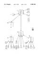
- FIG. 1shows a block diagram of a preferred embodiment of the invention
- FIG. 2is a drawing of the machine monitor element of a preferred embodiment of the invention.
- FIG. 3shows a block diagram of the machine monitor element of a preferred embodiment of the invention
- FIG. 4shows a block diagram of the command station element of a preferred embodiment of the invention
- FIG. 5shows a block diagram of the transmit and receive sections of the machine monitor and the command station of an alternative embodiment of the invention
- FIG. 6shows a block diagram of the machine monitor element of an alternative embodiment of the invention.
- FIG. 7shows a block diagram of the repeater element of a preferred embodiment of the invention.
- FIG. 8is functional block diagram of the system of FIG. 1, and illustrating the basic communication signal flow when a time-division communication protocol is employed;
- FIG. 9is a time-division schedule for the time-division communication protocol illustrated in FIG. 8.
- FIG. 10shows a block diagram of an installation and control unit in accordance with the invention.
- FIG. 1a block diagram of a wireless monitoring system is shown in FIG. 1.
- the system shown in FIG. 1is used when it is desirable to remotely monitor certain machine characteristics, but it is undesirable to install wiring between a monitoring station and a sensor on the machine. More specifically, the system is employed to monitor physical characteristics, such as speed, vibration, flux or other electromagnetic characteristics, temperature, and pressure, of machines and processes, such as those in a manufacturing plant.
- the basic components of the systeminclude: (1) one or more machine monitors 4 which are placed in various locations on, or in, one or more machines and which transmit wireless signals containing status data representative of the status of the machine and the status of the monitor, the machine status data being representative of machine characteristics such as vibration, electromagnetic energy, and temperature, the monitor status data being representative of monitor characteristics such as the condition of the monitor's battery, circuitry, and sensors; (2) a command station 6 which transmits commands and information to the machine monitors 4, receives data transmitted from the machine monitors 4, and formats the data as desired by an operator; and (3) one or more repeaters 8 as needed to facilitate communication between the machine monitors 4 and the command station 6, especially when site conditions make such aid necessary.
- the basic components of the systemmay be configured in various ways, some of which are illustrated in FIG. 1, to meet the requirements of the particular location where the system is used. If a particular machine is located such that machine monitors 4 placed on the machine are beyond the receiving range of the command station 6, or are out of the line of sight to the command station 6, a properly located repeater 8 is used to receive the signals from the machine monitors 4 and retransmit the signals to the command station 6. In some situations, more than one repeater 8 is necessary to provide for communication between the machine monitors 4 and the command station 6. In other situations, direct communication between the command station 6 and the machine monitors 4 is possible without the use of a repeater 8.
- the machine monitor 4 of FIG. 1is contained in a compact housing 402, such as a two-inch diameter by three-inch long cylinder with self-contained attachment means 404, such as a magnetic mount, so that the monitor may be easily attached to the machine even in cramped locations.
- a compact housing 402such as a two-inch diameter by three-inch long cylinder with self-contained attachment means 404, such as a magnetic mount, so that the monitor may be easily attached to the machine even in cramped locations.
- an antenna 406is preferably integrated with the housing 402.
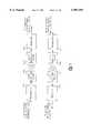
- FIG. 3a functional block diagram of the machine monitor 4 of FIG. 1 is shown.
- Each machine monitor 4contains at least one sensor 408 which is integrated with the machine monitor housing in such a manner that the desired machine characteristic is accurately measured when the machine monitor housing is fastened to the machine.
- sensors 408such as a flux sensor, two temperature sensors, an RF sensor, and two vibration sensors.
- the machine monitor 4has connectors 410 so that one or more sensors 408 may be interfaced with the data processing and transmission circuitry of the machine monitor 4. In this manner, the characteristics of interest may be measured at several locations on the machine and then transmitted from only one machine monitor 4.
- the integrated and remote sensors 408are devices such as small, low-power, low-cost accelerometers, and instantaneous turn-on solid-state temperature sensors.
- the accelerometerssuch as the type number 353B18, have an accuracy of ⁇ 5% from 1 to 10000 Hz and ⁇ 3 dB up to 30 kHz, and a turn-on settling time of less than five seconds.
- the temperature sensorssuch as the type number LM60, have an accuracy of ⁇ 2° C. over a 0 to 80° C. temperature range.
- the sensor signalsare amplified by an amplifier 412, such as a digitally-controlled variable gain amplifier incorporating a chip of type number LM6684.
- the sensor signalsare filtered to eliminate aliasing by means of an anti-aliasing filter 414, such as a simple resistorcapacitor (RC) low-pass filter or a two-pole Sallen-Key active filter, and are then converted into digital format by an analog-to-digital converter 416, such as a 16-bit Sigma-Delta converter of type number CS5330.
- an amplifier 412such as a digitally-controlled variable gain amplifier incorporating a chip of type number LM6684.
- the sensor signalsare filtered to eliminate aliasing by means of an anti-aliasing filter 414, such as a simple resistorcapacitor (RC) low-pass filter or a two-pole Sallen-Key active filter, and are then converted into digital format by an analog-to-digital converter 416, such as a 16-bit Sigma-Del
- the digital sensor signalsare fed to a monitor computer 418, such as the Toshiba TMP93CM41 microcomputer. Examples of circuits incorporating this microcomputer are detailed in the Toshiba 16-Bit Microcontroller TLCS-900/L MCU Series (2) Data Book (March 1995).
- the monitor computer 418includes a data processor 420 which performs 16-bit operations with 32-bit extended registers.
- the monitor computer 418also incorporates a memory 422 consisting of at least 32 kilobytes of static RAM, a timer 424, a serial interface 426, and a battery status monitor circuit 428.
- the monitor 4also includes an internal self-test capability for the electronics and sensors to determine the monitor's own status, which can be transmitted by the monitor 4 to the command station 6 as status data.
- a power supply 438such as a replaceable "D-cell" flashlight battery provides the electrical power necessary for the functioning of the active elements of the machine monitor 4. Under normal operational conditions, such a battery will provide power for the machine monitor 4 for at least one year.
- the power supply 438may alternatively consist of a rechargeable battery, such as a nickel-cadmium cell, and a charging voltage source, such as a solar cell or a wire coil moving across a magnetic field produced by the machine on which the machine monitor 4 is attached.
- the battery voltageis monitored by a battery status monitor circuit 428 which provides a battery status message to the monitor computer 418.
- the monitor computer 418is programmed to transmit this battery status message to the command station 6 as status data, and to transmit a battery status alert message when the battery voltage falls below a programmed threshold level.
- the sensors 408are not continuously on, but are turned on by the monitor 4 at intervals which have been programmed into the monitor computer 418.
- the duration of the measurement interval, during which the sensors 408 are on,is preferably about three seconds, just long enough for the sensors 408 to settle and take a measurement.
- the frequency of the measurement intervalis selectable by the operator and can vary substantially depending on needs, including the need to conserve battery power.
- the monitor computer 418remains in a standby mode for a majority of the time in the preferred embodiment, requiring less than 100 ⁇ A of current, and becomes active only at scheduled times as determined by an established communication protocol.
- the timer 424which is the monitor computer's only active component while in standby mode, causes the data processor 420 to enter an operational mode and begin processing data from the sensors 408 at scheduled times.
- the data processing tasksinclude such functions as (1) production of time wave form vibration data corresponding to the sensor signals (which may include selectable peak hold vibration signal processing with associated peak hold circuitry 417 similar to that disclosed in co-pending U.S. application Ser. No. 08/555,296, filed Nov.
- the data processor 420either sends the processed data over the serial interface 426 to be immediately transmitted, or stores the data in memory 422 for transmission at a later time.
- machinesare fitted with tachometer sensors 5a-c.
- a tachometer 5a-cis preferably grouped with other monitors 4 which are attached to the same machine and which are slaved to the same repeater 8, as illustrated in FIG. 1.
- the tachometers 5a-cfunction to assist vibration sensors 408 associated with the monitors 4 by measuring machine RPM and providing RPM data to the monitors 4 so that vibration measurements can be correlated with "current" RPM.
- At least two types of tachometers 5a-cmay be employed.
- Another type of tachometer 5a-ctransmits a tachometer pulse indicating the start of each revolution of the machine. This tachometer pulse is immediately relayed to the vibration sensors and monitors 4 by way of the repeater 8.
- a communication protocol(hereinafter referred to as a time-division communication protocol) is employed for conducting a periodic (preferably once every 60 seconds) status poll of the monitors 4.
- the protocolinvolves the use of a time slice schedule or status poll, such as the time slice schedule 18 shown in FIG. 9, where each repeater 8, monitor 4, and sensor, such as a tachometer 5, is allowed to transmit and in some cases receive in a manner that reduces or eliminates the likelihood of interference from two or more devices transmitting at the same time.
- a time slice schedule or status pollsuch as the time slice schedule 18 shown in FIG. 9, where each repeater 8, monitor 4, and sensor, such as a tachometer 5, is allowed to transmit and in some cases receive in a manner that reduces or eliminates the likelihood of interference from two or more devices transmitting at the same time.
- each status pollall devices are resychronized.
- FIG. 8illustrates a typical preferred time-division communication protocol for the system of FIG. 1 (excluding tachometers 5a-c) in accordance with the time slice schedule 18 shown in FIG. 9.
- the command station 6transmits a status request to monitor 41, and monitor 41 responds by transmitting the requested status information to the command station 6 during time slice 24.
- the status request transmitted by the command station 6will include instructions for which data and which functions the monitor 41 is to perform.
- the desired data and functionsare programmed into the monitor 41 and the status request is simply a request for the monitor 41 to perform functions and transmit data in accordance with its programming.
- the command and responseare transmitted by the command station 6 and monitor 41 a few times to ensure proper transmission and receipt.
- a small amount of dead time 21is scheduled between transmission of the command during time slice 22 and transmission of the response during time slice 24 to ensure that the command station 6 and monitor 41 do not transmit at the same time.
- the quantity of data transmitted (i.e., vibration, temperature, spectral, or other) by the monitor 41 during status pollingis preferably kept to a minimum to reduce the length of time required to complete the time slice schedule 18.
- the command station 6Following receipt of the response during time slice 24, the command station 6 next addresses monitor 4k and requests its status. The response from monitor 4k is transmitted and received during time slice 26. In similar fashion, each monitor 4 in the system is sequentially requested to provide a status to the command station 6 in accordance with the prearranged time slice schedule 18.
- Special requests for data sensing, data analysis, data transmission, and data storagecan also be transmitted by the command station 6 to one or more monitors 4. Such special requests are additional to the data and functions provided by monitors 4 during normal status polling. For example, if a particular machine is suspected of having an anomalous condition, it might be useful to instruct that machine's monitors 4 to begin collecting and storing specific types of data for specific types of analysis, such as vibration time waveform data for zoom processing.
- the monitor computer 418can also be programmed or otherwise requested to perform the zoom processing itself and store only the results of the zoom processing for later transmission to the command station 6. When transmitted to the command station 6, the data stored in accordance with the special request can be further analyzed or otherwise evaluated to diagnose the suspect machine condition.
- the command station 6can be connected to a PC network 10 as shown in FIG. 8. When so connected, the command station 6 is able to transfer data and information directly to the PC network 10 for analysis and archival storage.
- the PC network 10also enables an operator to reformat the time slice schedule 18 of FIG. 9.
- the time slice schedule 18can be reformatted by changing the order of devices within the schedule 18, changing the length of time allotted to individual slices, and changing the frequency at which status polls will be conducted. While the above-described time-division methodology can take on many different configurations, some preferences are hereby noted.
- each device in the systemis assigned a status poll time slice offset (defined during installation or reconfiguration) which represents the time difference (in milliseconds) between the start of the entire status poll sequence and the start of the assigned time slice for that device.
- a status poll messagefrom a master device (i.e., command station 6 or repeater 8) to another device (repeater, sensor, monitor) takes no more than 4 milliseconds.
- master devicei.e., command station 6 or repeater 8
- another devicepeerater, sensor, monitor
- all devicesmust be properly synchronized to ensure that the proper devices will turn on at the proper time. If devices become unsynchronized such that a device listens or transmits before or after an intended receiving device turns on, then communication may break down. Therefore, to ensure proper synchronization each device is resychronized during every status poll.
- Each devicereceives its own status poll message from the command station 6.
- Sensorssuch as tachometers 5a-c respond immediately to the status poll message, typically in less than 4 milliseconds.
- Repeaters 8get responses from their assigned sensors and propagate the status poll message to other repeaters 8 on an individual basis.
- the command station 6sends the status poll message first to sensors to which the command station 6 communicates directly with. Next, the command station 6 sends the status poll message to a first repeater branch. When the status poll response comes back from a first branch, the command station 6 sends the status poll message to a second repeater branch, and so on. If the status poll message rolls over a repeater branch and reaches a repeater 8 with a few sub-branches, then the status poll goes over a first sub-branch comes back and goes to a second sub-branch, and so on. When the status poll response goes back to the command station 6 each repeater 8 adds its own response and the responses of all monitors 4 assigned to it.
- the time slice scheduling methodologyprovides for a highly flexible and adaptable system by enabling plant operators to conveniently add, remove, or otherwise rearrange system components. For example, when plant personnel need to add an additional repeater 8e and monitor 4m, the time slice schedule 18 is easily lengthened to accommodate status polling of the new monitor 4m by adding time slices 86-92.
- Each monitor 4 and repeater 8is sent from the factory in a "blank", "unconfigured” condition. In this state, the monitor computer 418 will operate in its standby (low power) mode as previously described. When a small permanent magnet is brought near the reed switch 425, the monitor's receiver turns on for 0.1 seconds. If no messages are received during this 0.1 second time period, the sensor resumes its standby operational mode.
- the usercarries an installation and configuration unit, or ICU 9 as illustrated in FIGS. 1 and 10, which in a preferred embodiment consists of a device such as a portable computer modified to accommodate transmission and reception of wireless commands and signals.
- ICU 9can be built into the repeaters 8 and monitors 4.
- the ICU 9includes an antenna 902 and transceiver 908 which combine to enable transmission and reception of wireless signals.
- An ICU computer 912provides control of user interfaces, preferably a keyboard 920 and LCD display 922, for performing installation and configuration.
- Wireless commands and signalsare generated by the processor 914 in accordance with user inputs and processor programming. Commands are then passed over the serial interface 910 of the transceiver where the command is modulated by modulator 906 and amplified by RF power amplifier 904. The modulated command is then transmitted by antenna 902.
- Incoming wireless signalsare received by antenna 902, demodulated by demodulator 906, and passed over the serial interface 910 to the ICU computer 912.
- Sensor data received by incoming wireless signalsis processed by processor 914 and can be stored in memory 916.
- a timer 918is utilized to provide the timing needed by the ICU computer 912 for sending and receiving signals. All possible sources of arcing within the ICU 9 are preferably sealed or otherwise accommodated to prevent the ICU 9 from becoming a possible ignition source in hazardous environments.
- the userTo install a new device, the user types information into the ICU 9 concerning the installation of the monitor 4 and is requested by the ICU 9 to place the monitor 4 in startup configuration using the permanent magnet.
- the ICU 9communicates with the monitor 4 on channel-0 (the configuration channel).
- the ICU 9enables the user to determine transmitter signal strengths and to assign the monitor 4 to a repeater 8 if necessary. It also enables the user to assign the monitor 4 a normal communication channel and can indicate to the user the signal strength as seen by the command station 6.
- a single communication channel, or frequencyis used for all communication, including configuration and normal communication (e.g., normal status polling and other scheduled communications).
- configurationtakes place after normal communication is completed if the spread spectrum pseudo-noise (PN) code (as further described below) used for configuration is the same as the PN code used for normal communication.
- PNspread spectrum pseudo-noise
- a more preferred method of employing single channel communicationis to utilize a distinct PN code for configuration and a distinct PN code for normal communication so that configuration can occur during normal communication without interference.
- the usercan employ the ICU 9 to determine where repeaters 8 must be placed and how to configure (program) them. The user does this by typing the necessary information on the ICU menu through the keyboard 920 and pressing the "configure” button on the repeater 8. This causes the repeater 8 to wake up and listen for configuration commands for 15 seconds. The user then presses the "configure" function key on the ICU keyboard 920, causing the ICU 9 to transmit the configuration parameters on a special, "configuration" communication frequency to the repeater 8. When the repeater 8 receives this command, it will set up its configuration parameters (address, communication parameters, and others) and transmit an acknowledge message back to the ICU 9.
- the repeater 8changes to the normal communication channel and begins to adjust its transmission strength and the transmission strength of the device from which it receives commands. After this is done, a repeater 8 initiates the process of processing configuration polls.
- Configuration pollsmay be issued, for example, every 15 seconds. The purpose of these polls is to enable the ICU 9 to determine and display to the user the communication strength of each repeater 8 and monitor 4. This information is updated on the ICU 9 display every 15 seconds, enabling the user to roam around the plant and install repeaters 8 and monitors 4 where necessary, and thereby install a functioning system.
- the 15 second configuration pollsare routinely transmitted by the command station 6 and function as follows:
- the command station 6transmits a configuration status poll command.
- Each monitor 4 and repeater 8powers up its transceivers and transmits a reply sequence based upon its configured poll slice value.
- the command station 6transmits a composite message to the ICU 9 telling it the results of the status poll.
- the ICU 9then updates its display 922 with this information.
- the ICU 9After the ICU 9 has received the status information from the command station 6 it transmits a reply back to the command station 6, informing the command station 6 of any functions which the user wants it to perform. This enables the ICU 9 to instruct monitors 4 and repeaters 8 (indirectly via the command station 6) to return to the configuration channel for re-configuration or other functions.
- the configuration commandis transmitted on the configuration channel by the ICU 9 and contains the following information:
- This commandis never received by the command station 6, or by monitors 4 and repeaters 8 which are already configured, since it is transmitted on a special configuration channel.
- Commands which can be sent by the command station 6include the following:
- the ICU 9is assigned as a special sensor unit to the command station 6 with an address of -1 and the initial poll slice 20. This initial time slice 20 is reserved for communication with the ICU 9 to tell the command station 6 to switch to configuration mode or to issue some special commands.
- the ICU 9can also communicate with each repeater 8. After a particular repeater 8 receives a final response to a status poll 18 from its group of monitors 4, there is a 4 millisecond time slot for the ICU 9 to transmit a short status message to a repeater 8. In an alternate embodiment, the functions of the ICU 9 are built into each monitor 4.
- devices which communicate directly with the command station 6are configured first. Each device is separately configured.
- a Configuration Poll Commandis issued by the command station 6 every 15 seconds and the poll results are transmitted to the ICU 9.
- the ICU 9also responds to the status polls by transmitting its status directly to the command station 6.
- the userwalks around with the ICU 9. Every 15 seconds, the command station signal strengths are determined by the ICU 9 from the status poll results being transmitted by the command station 6.
- the userWhen the ICU receive signal strength falls below a certain level, the user knows that a repeater 8 (or monitor 4) should be installed and configured. The user then keys in the necessary information and causes the ICU 9 to transmit the configuration information to the device being configured.
- the ICU 9commands the device to transmit a signal strength scan using a predefined code.
- the scan code for each strength levelincludes unique identifying information.
- the command station 6receives the scan signals and, after completion of the scan, transmits the best repeater transmission level to the ICU 9 which then relays it to the device.
- the devicesets its transmitter strength to this level and sends a message to the command station 6 requesting a transmission scan.
- the device being configuredsends a message to the command station 6 requesting the command station's best transmission level. This request is acknowledged by the command station 6 by transmitting a special entry code which ends the device's configuration if it is a monitor 4. If the device being installed is a repeater 8, it is preferable to temporarily install a few probe sensors in places where monitors 4 will ultimately be installed.
- the probe sensorslisten to the last transmission scans of the repeater 8 being installed and the command station 6 and transmits the three best signal levels to the ICU 9.
- the ICU 9checks whether the probe sensors can receive a good transmission from the repeater 8 being installed and whether they can be assigned to the command station 6. If all probe sensors can receive good transmissions only from the repeater 8 being installed, the ICU 9 transmits a final message to the command station 6 informing it that device installation is complete. In all other cases, both the command station 6 and the device being installed terminate communication with the ICU 9. The user is prompted about his decision on the device arrangement and the user's decision is sent to the command station 6 when it next communicates with the ICU 9.
- Devices which do not communicate directly with the command station 6are installed in similar fashion with the exception that instead of communicating with the command station 6, the ICU 9 communicates with the immediate repeater 8 or other command device of the device being installed. After a new device is configured with its immediate repeater 8, the immediate repeater 8 sends a Unit Configuration Request to the command station 6 (possibly by way other intermediate repeaters 8). After a response is received from the command station 6, the device is configured with the system. All repeaters 8 in the communication chain between the command station 6 and the immediate repeater 8 listen to the command station response and update their monitor/repeater lists accordingly.
- the ICU 9When a repeater installation is complete, the ICU 9 responds to the next 15 second poll by transmitting its status and a command to the designated repeater 8, instructing the repeater 8 to inform the command station 6 as to which repeater 8 the ICU 9 is currently communicating through. Subsequent status polls are transmitted via the repeater 8.
- All devicesare installed in the order of their position in the time slice schedule 18. Installation can be terminated and resumed at any time by transmitting the appropriate signal from the ICU 9 to the command station 6.
- the userinitiates system startup from the command station 6. This causes a startup command to be issued, terminates the 15 second polls, and initiates the 60 second polls. In addition, all monitors 4 start their normal data collection functions.
- a Re-configuration Poll Commandprecedes the Configuration Poll Command in an already existing system and when new devices will be assigned a time slice which is not at the end of the time slice schedule 18. In the latter case, a time window for new devices to receive a status poll will be made by adding a time delay to some poll slice values for existing devices. The poll slice values might also be subject to additional changes caused by longer transmissions back to the command station 6.
- the command station 6is informed by the ICU 9 when on-line setup is occurring and all command station activities are stopped, except for the configuration status poll activities, and the command station 6 enters its installation/configuration mode. In the case of a new system, the command station 6 is powered up and set by the ICU 9 for configuration.
- the monitor 4receives a unique monitor 4 ID number (address), a date/time synchronization by the command station 6 (current time/date), and a date/time of a monitor's first status poll. At the date/time of the first status poll, the monitor 4 will turn on its transceiver and wait to receive a status poll command. If no status poll command is received within 60 seconds, the monitor 4 will go into a "lost synch" loop.
- the repeaters 8 and the command station 6record the monitor's status as "not responding" and the date/time the monitor 4 went out of service is logged in a communications journal file by the command station 6. If the monitor 4 returns to service some time later, the date and time of this is also recorded. There are several reasons why a monitor 4 might not respond, including poor communications signal strength, transmission noise, clock error affecting the synchronization of the status poll processing, low battery, hardware failure, removal of monitor 4, and others. If the monitor timer 424 has become unsynchronized with the command station 6, it could be listening for a status poll command at the wrong time. In this case, every minute, the monitor 4 listens for a longer and longer time period so that it can become synchronized.
- the monitor 4will begin to process its "lost synch" loop in order to re-establish communications when the problem has been resolved, as follows:
- the monitor 4powers up once every 60 seconds. As data is acquired by the monitors 4, it is preferably stored in memory 422 for a period of time. When the monitor 4 transmits an alarm message to the command station 6, the command station 6 may then command the monitor 4 to transmit its most recently stored data.
- the monitor 4can be programmed (either at the factory before being shipped, by the ICU 9 during installation or reconfiguration, or through appropriate wireless commands transmitted by the command station 6 before, during, or after installation) to store spectral data for each vibration measurement obtained during the most recent week of measurement activity.
- the monitor 4is in alarm and the command station 6 issues the appropriate command, the monitor 4 transmits all of its spectral data that has been stored over a previous time period, such as the past week. The spectral data can then be further analyzed to help diagnose causal factors which produced the alarm condition.
- Non-time division communicationis particularly useful for supplementing data and information obtained during time-division status polling, such as when an alarm condition is signaled during a status poll. For example, when a time-division status poll is completed and a particular monitor 4 has communicated to the command station 6 that an alarm condition exists, the command station 6 will utilize a non-time division communication protocol to command the monitor 4 to transmit its stored data. During non-time division communication, there is no transmission or reception time scheduling.
- the command station 6transmits a command requesting stored data from a particular monitor 4 (or requesting the monitor 4 to perform other functions including status polling). If the communication link between the monitor 4 and command station 6 is by way of one or more repeaters 8, the first repeater 8 in the chain will receive the request for data from the command station 6 and acknowledge such receipt by transmitting an "ACK" signal. The command station 6 receives ACK and waits for data transmission while the first repeater 8 transmits the data request to the monitor 4 or the next repeater 8 in the chain, depending on the system arrangement. In contrast to the methodology employed during time-division communication, all repeaters 8 which are included in the communication chain remain on after the data request has been repeated and wait for the requested data to be transmitted. When the data has been received and retransmitted to the next repeater 8 or command station 6, the repeater 8 turns off.
- monitor 4c shown in FIG. 8transmitted an alarm message during a status poll.
- the communication chainassuming no blockage of repeaters 8, includes repeaters 8b and 8c.
- the command station 6transmits a request for data to repeater 8c, which powers up to listen for command signals at a predetermined time following status polling.
- Repeater 8ctransmits ACK to the command station 6 and repeats or transmits the data request to repeater 8b.
- Repeater 8ctransmits ACK to repeater 8b to acknowledge proper receipt of the data request and transmits the data request to monitor 4c.
- each repeater 8b, 8cAfter repeating the data request, each repeater 8b, 8c remains on in asynchronous fashion and waits for transmission of the requested data. The repeaters 8b, 8c do not turn off until the requested data has been received and retransmitted to the next repeater or to the command station 6.
- the command station 6looks at the results of the status poll responses. When it is discovered that a device did not respond to the status request, the command station 6 will continue normal status polling for 15 minutes to allow time for the lost device to resynchronize. If resychronization is not successful within 15 minutes, then the cause is probably either a depleted battery or a blocked communication path. In situations where battery depletion is unlikely, the command station 6 assumes that the communication path is blocked and signals the blocked condition to the user. To compensate, the command station 6 selects a group of repeaters 8 and sends them a command to be relayed to the lost device during their time slices. Within this command, the command station 6 requests a transmission strength scan to be performed by the lost device at a specified time Tx.
- all selected repeaters 8listen for a fixed amount of time, after which the repeaters 8 send the results of the strength scan to the command station 6.
- the command station 6selects one repeater 8 from those which indicated positive results of the strength scan and commands the selected repeater 8 to perform its transmission scan with encoded best transmission strength of the lost device at time Tx+60 seconds. After this scan has completed, the lost device replies to its new repeater 8 and sends its best transmission strength.
- the new repeater 8acknowledges the lost device's transmission by informing it that its temporary status poll slice will be the ICU time slot of the new repeater 8. After synchronization of the lost device with the new repeater 8, the command station 6 sends the Re-configuration poll command to make a permanent time slice for the lost device.
- the command station 6maintains a Re-Configuration Look-Up Table in which a list is maintained for all devices that each repeater 8 can communicate with at any given time. When a device becomes lost due to blocked communication, the command station 6 reassigns the lost device to a new repeater 8.
- the monitor 4also conserves power by transmitting data only during preprogrammed intervals or time slots where the timing of the intervals is provided by the timer 424.
- Each transmit intervaleither coincides with the measurement intervals of the sensors 408 so that real-time sensor data is transmitted, or the transmit intervals are scheduled so that data previously stored in the machine monitor memory 422 is transmitted.
- Transmission schedulingis controlled by the user or operator according to the desired communication protocol programmed into the monitor computer 418.
- the protocolcan be programmed into the monitor computer 418 either before installation or during installation. Protocols can also be installed or changed from the command station 6 after installation, thereby providing the system with the flexibility needed to accommodate system changes such as the addition, removal, or replacement of monitors 4.
- Data (including status) and other communication signalsare preferably transmitted in a spread spectrum format.
- a radio-frequency (RF) signalis modulated using a digital coding sequence which spreads the signal energy over a fairly broad bandwidth, thereby making the signal resistant to interference from other nearby RF emitters.
- a preferred embodimentincorporates a radio frequency (RF) transceiver 430 which performs data transmission as well as data reception.
- the transceiver 430 of this preferred embodimentfurther consists of a modulator/demodulator circuit 432, such as the Harris HSP 3824 spread spectrum processor, which, in the transmit mode, modulates a carrier wave (CW) signal with the baseband digital sensor data.
- the CW signalis fed to an RF power amplifier circuit 434, such as the Hewlett Packard HPMX3003, which amplifies the CW signal into an RF signal to be transmitted from the antenna 406.
- the transceiver 430also provides for receiving and decoding messages from the command station 6 which are transmitted to the machine monitor 4 in the form of RF signals.
- Such messagesinclude: (1) timing messages which synchronize the machine monitor timer 424 to the command station computer's clock; (2) scheduling messages which tell the machine monitor 4 when, what, and how to measure, analyze, and transmit the sensor data and when to receive other messages from the command station 6; (3) confirmation messages which tell the machine monitor 4 that the command station 6 has accurately received the sensor data transmissions; (4) special request messages which command the machine monitor 4 to perform special data analysis functions (or special data sensing, storage, or transmission); and (5) reprogramming messages which provide new measurement, analysis, and transmission programming for the monitor computer 418.
- the RF signals from the command station 6are received by the antenna 406, down-converted to IF by the up-converter/down-converter circuit 434, demodulated by the modulator/demodulator circuit 432 to form baseband data signals, and fed over the serial interface 426 to the data processor 420.
- the receive circuits of the machine monitor transceiver 430are not continuously on, but, to conserve power, are turned on only when necessary to receive messages from the command station 6.
- the "on time" of the receive circuitsis scheduled by the operator according to instructions programmed into the monitor computer 418. At the scheduled times, a message from the timer 424 causes the monitor computer 418 to send power-on messages to the receive circuits of the monitor transceiver 430.
- the receive circuitsstay energized until an error-free message is received from the command station 6, at which time the monitor computer 418 sends a shut-down message to the receive circuits of the monitor transceiver 430.
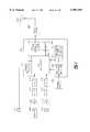
- a block diagram of the command station 6 of FIG. 1is shown in FIG. 4.
- the RF signal transmitted from the machine monitor 4is received by an antenna 602 at the command station 6.
- a transceiver 604which includes an RF power amplifier/down-converter circuit 606 and a modulator/demodulator circuit 608, such as those previously discussed in the description of the machine monitor 4, downconverts and demodulates the RF signal to recover the digital sensor data.
- the sensor datais fed over a serial interface 610 to a command station computer 612, such as a personal computer incorporating a Pentium processor or equivalent, where the information is preferably monitored in real-time for machine fault conditions and is entered into a data base for off-line trend analysis.
- the transmit circuits of the command station transceiver 604provide for the transmission of timing, scheduling, and programming messages to the machine monitor 4.
- the machine monitor 4communicates with the command station 6 by means of light waves.
- the machine monitor transmitter 446 of this embodimentreceives digital sensor data from the machine monitor serial interface 426 and modulates an electrical signal which drives a light emitting device 448, such as a light emitting diode (LED).
- the light emitting device 448converts the electrical signal from the transmitter 446 into light waves which are modulated with the digital sensor information.
- a light detecting device 616such as a photodiode, receives the light waves from the light emitting device 448 of the machine monitor 4 and converts the light waves into an electrical signal.
- the command station receiver 618amplifies and demodulates the electrical signal at the output of the light detecting device 616 to form a digital electrical signal which is compatible with the data format of the command station serial interface 610.
- the sensor datais then passed over the serial interface 610 to the command station computer 612 for processing as described above.
- a similar series of operationsare performed to transmit messages from the command station 6 to the machine monitor 4 as shown in FIG. 5.
- a preferred embodiment of the inventionprovides for error detection in the data that the command station 6 receives from the machine monitor 4.
- the machine monitor 4transmits a 16-bit cyclic redundancy check (CRC16) message immediately after transmitting the sensor data message.
- CRC16cyclic redundancy check
- the command station 6Upon receipt of the sensor data message and the CRC16 message, the command station 6 computes its own CRC16 message based on the received data and compares it to the received CRC16 message. If the received and computed CRC16 messages match, then no errors exist in the received sensor data, and the command station 6 transmits an acknowledgment message to the machine monitor 4 to confirm that the sensor data has been accurately received.
- data transmission times for each machine monitor 4are scheduled such that only one machine monitor 4 is transmitting at any given time (time division mutliplexing).
- time division mutliplexingBy accurate synchronization of the machine monitor timer 424 with the command station clock, the command station 6 "listens" for the transmission of only one machine monitor 4 at the precise time when the command station 6 has commanded the machine monitor 4 to transmit.
- each machine monitor 4transmits a unique identification code prior to the sensor data message.
- the identification code combined with the sensor data messagecomprise a data packet.
- the identification codeis stored within the machine monitor 4 by means such as a set of DIP switches or a non-volatile RAM, the state of which determines the value of the identification code to be stored in the monitor computer memory.
- the identification code transmitted by the machine monitor 4is received by the command station 6, and the command station computer 612 compares the code to values stored in a table within the command station computer 612.
- the possibility of interferenceis reduced further by programming each machine monitor 4 to transmit with its own distinct spread spectrum pseudo-noise (PN) code (code-division multiplexing).
- PNpseudo-noise
- each machine monitor transceiver 430is assigned a unique frequency band over which to transmit the sensor data to the command station 6.
- the command station transceiver 604as commanded by the command station computer 612, listens for a particular machine monitor 4 on the assigned frequency band at the designated transmission time.
- the machine monitor 4could also incorporate means of continuously sensing an extreme fault condition of the machine being monitored, such as the use of tuned reed switches for detecting an extreme vibration condition.
- the monitor computer 418"wakes up" from the standby mode, processes the signal from its one or more sensors 408, and transmits a data packet consisting of the machine monitor's identification code and the sensor data to the command station 6.
- these fault messagesare transmitted only during special time intervals which are individually assigned to each machine monitor 4 specifically for the transmission of fault messages.
- the command station 6listens for fault messages from the machine monitors 4. Depending on the number of machine monitors 4 under the control of a particular command station 6, several such fault message intervals are available to each machine monitor 4 between the scheduled intervals for "regular" sensor data transmissions.
- FIG. 6is a block diagram of a receiverless machine monitor 4 of an alternative embodiment of the invention.
- This embodimentincludes a transmitter 440, not a transceiver. Instead of receiving wireless messages from the command station 6 to set the machine monitor's start-up and shut-down times, these times are programmed into the monitor computer memory 422 via an interface cable prior to installation of the machine monitor 4 in the machine. During programming, the interface cable is connected between the monitor computer 418 and the command station computer 612, utilizing interface connectors 442 and 614 in the machine monitor 4 and the command station 6, respectively.
- Synchronization of the machine monitor's timer 424 with the command station's clockis also accomplished via the cable interface.
- the data analysis function to be performed by the machine monitor 4is likewise programmed into the machine monitor computer 418 via the cable interface prior to installation of the machine monitor 4 in the machine to be monitored. Once programming and timing calibration are complete, the interface cable is removed and the machine monitor 4 is attached to the machine.
- While the machine monitor 4is preferably battery powered to accommodate a completely wireless installation in the machine to be monitored, a second alternative embodiment of the invention is useful in those situations which require continuous monitoring of a machine characteristic, and a continuous source of power is available at the machine location.
- This alternative embodimentincorporates a power conditioner circuit so that the machine monitor 4 may be connected to the AC power source at the machine site.
- the power conditionerconverts the AC source voltage to the appropriate level of DC voltage for each component of the machine monitor 4 and filters the source voltage to remove noise generated on the AC line by nearby machinery.
- the repeater 8 of FIG. 1is shown in block diagram form in FIG. 7.
- the RF sensor data message from a machine monitor 4is received by the antenna 802, converted down to IF by the down-converter circuit 804, and demodulated by the modulator/demodulator circuit 806 to recover the original baseband sensor data.
- the sensor datais then passed over the serial interface 810 of the repeater computer 812 to the data processor 814.
- the sensor datais then either stored in memory 816 or is passed to the modulator/demodulator circuit 806 and the RF power amplifier/down-converter circuit 804 of the repeater transceiver 808 to create a "new" RF sensor data signal.
- This signalis transmitted from the repeater antenna 802 to the command station 6.
- the repeater 8operates in a similar fashion when relaying data from the command station 6 to the machine monitors 4.
- a timer 818provides the clock signals necessary for proper timing of the receive and transmit intervals for each machine monitor 4 assigned to the repeater 8.
- the repeater computer 812sets up the transceiver 808 with the correct spread-spectrum PN code for the particular machine monitor 4 that the repeater 8 is servicing at any given time.
- the repeater's transceiver 808 and computer 812are of the same type as, or are functionally equivalent to, the corresponding components of the machine monitor 4.
- the operation of the repeater 8is "transparent" to the other components of the system, that is, the other components function in the same manner as they would if the repeater 8 were unnecessary and not in the system.
- a repeater 8Since a repeater 8 is designed to service many machine monitors 4, a repeater 8 is typically operable at a higher duty cycle than that of a single machine monitor 4. For this reason, the repeater 8 is preferably continuously powered by a line carrying power to the repeater 8, such as a standard AC power outlet, or by power that is hard wired during installation. Alternatively, the repeater 8 may be battery powered with batteries that have greater storage capacity that those used in the monitors 4. Typically, the location of a repeater 8 is flexible enough to enable the repeater 8 to be hard wired for power, while still adequately servicing the machine monitors 4. For many installations, the ceiling of the facility provides an excellent location for repeaters 8. Continuous operation enables the repeater 8 to be continuously "listening" for fault messages from the machine monitors 4 which the repeater 8 services.
Landscapes
- Engineering & Computer Science (AREA)
- Physics & Mathematics (AREA)
- General Physics & Mathematics (AREA)
- Computer Networks & Wireless Communication (AREA)
- Signal Processing (AREA)
- Human Computer Interaction (AREA)
- Manufacturing & Machinery (AREA)
- Automation & Control Theory (AREA)
- Selective Calling Equipment (AREA)
Abstract
Description
Claims (58)
Priority Applications (4)
| Application Number | Priority Date | Filing Date | Title |
|---|---|---|---|
| US08/835,083US5907491A (en) | 1996-08-23 | 1997-04-04 | Wireless machine monitoring and communication system |
| PCT/US1997/015187WO1998045779A1 (en) | 1997-04-04 | 1997-08-28 | Wireless machine monitoring and communication system |
| EP97940675AEP1023662A1 (en) | 1997-04-04 | 1997-08-28 | Wireless machine monitoring and communication system |
| US09/073,626US6301514B1 (en) | 1996-08-23 | 1998-05-06 | Method and apparatus for configuring and synchronizing a wireless machine monitoring and communication system |
Applications Claiming Priority (2)
| Application Number | Priority Date | Filing Date | Title |
|---|---|---|---|
| US08/697,372US5854994A (en) | 1996-08-23 | 1996-08-23 | Vibration monitor and transmission system |
| US08/835,083US5907491A (en) | 1996-08-23 | 1997-04-04 | Wireless machine monitoring and communication system |
Related Parent Applications (1)
| Application Number | Title | Priority Date | Filing Date |
|---|---|---|---|
| US08/697,372Continuation-In-PartUS5854994A (en) | 1996-08-23 | 1996-08-23 | Vibration monitor and transmission system |
Related Child Applications (1)
| Application Number | Title | Priority Date | Filing Date |
|---|---|---|---|
| US09/073,626Continuation-In-PartUS6301514B1 (en) | 1996-08-23 | 1998-05-06 | Method and apparatus for configuring and synchronizing a wireless machine monitoring and communication system |
Publications (1)
| Publication Number | Publication Date |
|---|---|
| US5907491Atrue US5907491A (en) | 1999-05-25 |
Family
ID=25268528
Family Applications (1)
| Application Number | Title | Priority Date | Filing Date |
|---|---|---|---|
| US08/835,083Expired - LifetimeUS5907491A (en) | 1996-08-23 | 1997-04-04 | Wireless machine monitoring and communication system |
Country Status (3)
| Country | Link |
|---|---|
| US (1) | US5907491A (en) |
| EP (1) | EP1023662A1 (en) |
| WO (1) | WO1998045779A1 (en) |
Cited By (302)
| Publication number | Priority date | Publication date | Assignee | Title |
|---|---|---|---|---|
| WO2000003143A1 (en)* | 1998-07-13 | 2000-01-20 | Gte Internetworking Incorporated | Reconfigurable robot network |
| US6085121A (en)* | 1997-09-22 | 2000-07-04 | Design & Manufacturing Solutions, Inc. | Device and method for recommending dynamically preferred speeds for machining |
| US6098118A (en)* | 1996-05-22 | 2000-08-01 | Geovector Corp. | Method for controlling electronic devices in response to sensed conditions using physical characteristic signal indicating use or anticipated use of the electronic device |
| US6138078A (en)* | 1996-08-22 | 2000-10-24 | Csi Technology, Inc. | Machine monitor with tethered sensors |
| WO2000073866A1 (en)* | 1999-05-28 | 2000-12-07 | General Electric Company | An intelligent electronic device for monitoring non-electrical characteristics |
| US6167464A (en)* | 1998-09-23 | 2000-12-26 | Rockwell Technologies, Llc | Mobile human/machine interface for use with industrial control systems for controlling the operation of process executed on spatially separate machines |
| WO2001009576A1 (en)* | 1999-07-30 | 2001-02-08 | Eric Atherton | Plant condition measurement |
| US6202000B1 (en)* | 1997-12-30 | 2001-03-13 | Samsung Electronics Co., Ltd. | Monitoring system for semiconductor device fabrication facility |
| US6237034B1 (en)* | 1997-11-04 | 2001-05-22 | Nortel Networks Limited | Method and system for transmitting and receiving alarm notifications and acknowledgements within a telecommunications network |
| US6246325B1 (en)* | 1999-11-18 | 2001-06-12 | Agere Systems Guardian Corp. | Distributed communications system for reducing equipment down-time |
| WO2001050405A1 (en)* | 2000-01-06 | 2001-07-12 | Rapp Roy W Iii | A paperless tablet automation apparatus and method |
| US6285912B1 (en)* | 1996-10-25 | 2001-09-04 | Hubbell Incorporated | System for physically mounting a multifunction user interface to a basic multifunction sensor to access and control various parameters of a control network environment |
| US6301514B1 (en)* | 1996-08-23 | 2001-10-09 | Csi Technology, Inc. | Method and apparatus for configuring and synchronizing a wireless machine monitoring and communication system |
| US20010042121A1 (en)* | 2000-05-12 | 2001-11-15 | Isochron Data Corporation | Method and system for the optimal formating, reduction and compression of DEX/UCS data |
| US20010047410A1 (en)* | 2000-05-26 | 2001-11-29 | Isochron Data Corporation | System and apparatus for the remote monitoring and control of a computing component |
| US20010054083A1 (en)* | 1998-03-19 | 2001-12-20 | Isochron Data Corporation | System and method for monitoring and control of beverage dispensing equipment |
| US20020009975A1 (en)* | 2000-06-07 | 2002-01-24 | Janusz Gerald E. | Method and system for transmitting, receiving and collecting information related to a plurality of working components |
| US20020012323A1 (en)* | 1999-03-18 | 2002-01-31 | Petite Thomas D. | Systems and methods for enabling a mobile user to notify an automated monitoring system of an emergency situation |
| US20020016829A1 (en)* | 1998-03-19 | 2002-02-07 | Isochron Data Corporation | Remote data acquisition, transmission and analysis system including handheld wireless equipment |
| US6349266B1 (en)* | 1999-05-28 | 2002-02-19 | C.E. Electronics, Inc. | Remote control qualifier |
| US20020027504A1 (en)* | 1999-03-18 | 2002-03-07 | James Davis | System and method for controlling communication between a host computer and communication devices associated with remote devices in an automated monitoring system |
| US6370489B1 (en) | 1997-04-16 | 2002-04-09 | A.L. Air Data | Lamp monitoring and control system and method |
| US6400997B1 (en)* | 2000-01-06 | 2002-06-04 | Roy Rapp, III | Paperless tablet automation apparatus and method |
| EP1211655A2 (en) | 2000-11-30 | 2002-06-05 | Horst Prof. Dr. Ziegler | Method for radio data transmission |
| US6415188B1 (en)* | 1998-12-23 | 2002-07-02 | Dennis Sunga Fernandez | Method and apparatus for multi-sensor processing |
| WO2002052511A3 (en)* | 2000-12-22 | 2002-08-29 | Kendro Lab Products Inc | Equipment monitoring system and method |
| US20020125998A1 (en)* | 1998-06-22 | 2002-09-12 | Petite Thomas D. | System and method for monitoring and controlling remote devices |
| US6457038B1 (en) | 1998-03-19 | 2002-09-24 | Isochron Data Corporation | Wide area network operation's center that sends and receives data from vending machines |
| US6487375B2 (en)* | 2000-12-28 | 2002-11-26 | Xerox Corporation | System to communicate information from a plurality of machines to a remotely located receiver |
| US20030003865A1 (en)* | 2001-06-29 | 2003-01-02 | Defosse Erin M. | Method and system for interfacing a machine controller and a wireless network |
| US6505086B1 (en) | 2001-08-13 | 2003-01-07 | William A. Dodd, Jr. | XML sensor system |
| US20030044267A1 (en)* | 2001-08-30 | 2003-03-06 | Seagate Technology Llc | Assembly station with rotatable turret which forms and unloads a completed stack of articles |
| US20030097474A1 (en)* | 2000-05-12 | 2003-05-22 | Isochron Data Corporation | Method and system for the efficient communication of data with and between remote computing devices |
| US20030101257A1 (en)* | 2001-11-27 | 2003-05-29 | Isochron Data Corporation | Method and system for predicting the services needs of remote point of sale devices |
| US20030101262A1 (en)* | 2001-11-27 | 2003-05-29 | Isochron Data Corporation | Method and system for scheduling the maintenance of remotely monitored devices |
| US20030125050A1 (en)* | 2001-03-30 | 2003-07-03 | Sunao Takatori | Slave communication apparatus for used in radio lan system, control method of slave communication apparatus, and control program |
| US6598479B1 (en) | 2001-11-19 | 2003-07-29 | Csi Technology, Inc. | Integral magnet vibration sensor |
| US20030158954A1 (en)* | 2002-02-19 | 2003-08-21 | Williams Terry L. | Software-defined radio communication protocol translator |
| US20030158693A1 (en)* | 2000-05-16 | 2003-08-21 | Akinori Kai | Measurement data processing system |
| US6628993B1 (en)* | 1999-07-15 | 2003-09-30 | Robert Bosch Gmbh | Method and arrangement for the mutual monitoring of control units |
| US20030189496A1 (en)* | 2002-04-08 | 2003-10-09 | Tran Matthew P. | Central management of networked computers |
| US20030204371A1 (en)* | 2002-04-30 | 2003-10-30 | Chevron U.S.A. Inc. | Temporary wireless sensor network system |
| US20030204391A1 (en)* | 2002-04-30 | 2003-10-30 | Isochron Data Corporation | Method and system for interpreting information communicated in disparate dialects |
| US20030212508A1 (en)* | 2002-05-13 | 2003-11-13 | Bibelhausen David J. | Modular monitoring and protection system with open communication backbone |
| US20030212500A1 (en)* | 2002-05-13 | 2003-11-13 | Shupe Dan R. | Modular equipment dynamic condition monitoring system with multiple processors |
| US20040002835A1 (en)* | 2002-06-26 | 2004-01-01 | Nelson Matthew A. | Wireless, battery-less, asset sensor and communication system: apparatus and method |
| US20040001008A1 (en)* | 2002-06-27 | 2004-01-01 | Shuey Kenneth C. | Dynamic self-configuring metering network |
| US20040019461A1 (en)* | 2002-04-22 | 2004-01-29 | Kai Bouse | Machine fault information detection and reporting |
| US6687754B1 (en)* | 1998-08-27 | 2004-02-03 | Intel Corporation | Method of detecting a device in a network |
| WO2004008261A3 (en)* | 2002-07-10 | 2004-04-08 | Stg Aerospace Ltd | Improvements in or relating to networked communication devices |
| US20040082296A1 (en)* | 2000-12-22 | 2004-04-29 | Seekernet Incorporated | Network Formation in Asset-Tracking System Based on Asset Class |
| US20040083815A1 (en)* | 2002-11-06 | 2004-05-06 | Lam Clive Chemo | Pipe flaw detector |
| US6735630B1 (en) | 1999-10-06 | 2004-05-11 | Sensoria Corporation | Method for collecting data using compact internetworked wireless integrated network sensors (WINS) |
| US6745027B2 (en)* | 2000-12-22 | 2004-06-01 | Seekernet Incorporated | Class switched networks for tracking articles |
| EP1199680A3 (en)* | 2000-10-20 | 2004-06-16 | Nokia Corporation | A method for maintaining an object, and a maintenance system |
| US20040113810A1 (en)* | 2002-06-28 | 2004-06-17 | Mason Robert T. | Data collector for an automated meter reading system |
| US20040127958A1 (en)* | 2002-12-27 | 2004-07-01 | Mazar Scott Thomas | Advanced patient management system including interrogator/transceiver unit |
| US20040133653A1 (en)* | 1998-03-19 | 2004-07-08 | Cac Vending Systems, L.L.C. | System, method and apparatus for vending machine wireless audit and cashless transaction transport |
| US20040139803A1 (en)* | 2001-11-19 | 2004-07-22 | Robinson James C. | Multi-axis vibration sensor with integral magnet |
| US20040148039A1 (en)* | 2003-01-24 | 2004-07-29 | Farchmin David W | Position based machine control in an industrial automation environment |
| US20040154913A1 (en)* | 2001-03-12 | 2004-08-12 | Lah Ruben F. | Valve system and method for unheading a coke drum |
| US20040162626A1 (en)* | 2003-02-14 | 2004-08-19 | Farchmin David Walter | Location based programming and data management in an automated environment |
| US20040166881A1 (en)* | 2003-02-06 | 2004-08-26 | Farchmin David Walter | Phased array wireless location method and apparatus |
| US20040186679A1 (en)* | 2003-03-03 | 2004-09-23 | Yohko Ohtani | Connection test method and information processing apparatus performing same |
| US6804726B1 (en) | 1996-05-22 | 2004-10-12 | Geovector Corporation | Method and apparatus for controlling electrical devices in response to sensed conditions |
| US20040203874A1 (en)* | 2002-09-27 | 2004-10-14 | Brandt David D. | Machine associating method and apparatus |
| US20040213319A1 (en)* | 2002-09-30 | 2004-10-28 | Kevin Lancon | System of monitoring operating conditions of rotating equipment |
| US6813526B1 (en) | 2001-08-13 | 2004-11-02 | William A. Dodd, Jr. | Fleet maintenance method |
| US20040224713A1 (en)* | 2003-04-16 | 2004-11-11 | Karlheinz Schreyer | Method for radio transmission in an alarm signaling system |
| US6826607B1 (en) | 1999-10-06 | 2004-11-30 | Sensoria Corporation | Apparatus for internetworked hybrid wireless integrated network sensors (WINS) |
| US6832251B1 (en) | 1999-10-06 | 2004-12-14 | Sensoria Corporation | Method and apparatus for distributed signal processing among internetworked wireless integrated network sensors (WINS) |
| EP1486841A1 (en)* | 2003-06-11 | 2004-12-15 | Endress + Hauser GmbH + Co. KG | Method for indication of function of a field device in process automation technology |
| US20040260518A1 (en)* | 2001-02-16 | 2004-12-23 | Andreas Polz | Device and process for operation of automation components |
| US20050032549A1 (en)* | 2003-08-05 | 2005-02-10 | Matsushita Electric Industrial Co., Ltd | Communication apparatus |
| US6859831B1 (en) | 1999-10-06 | 2005-02-22 | Sensoria Corporation | Method and apparatus for internetworked wireless integrated network sensor (WINS) nodes |
| US20050043059A1 (en)* | 2000-08-09 | 2005-02-24 | Petite Thomas D. | Systems and methods for providing remote monitoring of electricity consumption for an electric meter |
| US20050052148A1 (en)* | 2001-10-23 | 2005-03-10 | Erik Carlson | Industrial robot system |
| US20050060396A1 (en)* | 2003-09-16 | 2005-03-17 | Yokogawa Electric Corporation | Device diagnosis system |
| US6886651B1 (en) | 2002-01-07 | 2005-05-03 | Massachusetts Institute Of Technology | Material transportation system |
| US20050093702A1 (en)* | 2000-12-22 | 2005-05-05 | Twitchell Robert W.Jr. | Manufacture of LPRF device wake up using wireless tag |
| US20050093703A1 (en)* | 2000-12-22 | 2005-05-05 | Twitchell Robert W.Jr. | Systems and methods having LPRF device wake up using wireless tag |
| US20050140510A1 (en)* | 2003-12-16 | 2005-06-30 | Kendro Laboratory Products, Lp (De Corp.) | Environmental monitoring module and method |
| US6925335B2 (en) | 2001-07-05 | 2005-08-02 | Isochron, Llc | Real-time alert mechanism for monitoring and controlling field assets via wireless and internet technologies |
| US20050188267A1 (en)* | 2004-02-06 | 2005-08-25 | Farchmin David W. | Location based diagnostics method and apparatus |
| US20050204061A1 (en)* | 2004-03-12 | 2005-09-15 | Farchmin David W. | Juxtaposition based machine addressing |
| US20050202798A1 (en)* | 2004-03-06 | 2005-09-15 | Alexander Kurz | Method and circuit arrangement for switching an electronic circuit into a power-saving mode |
| US20050215280A1 (en)* | 2000-12-22 | 2005-09-29 | Twitchell Jr Robert W | Lprf device wake up using wireless tag |
| US20050228528A1 (en)* | 2004-04-01 | 2005-10-13 | Farchmin David W | Location based material handling and processing |
| US20050248438A1 (en)* | 2004-05-04 | 2005-11-10 | Hughes Michael A | Semi-passive radio frequency identification (RFID) tag with active beacon |
| US20050262923A1 (en)* | 2004-05-27 | 2005-12-01 | Lawrence Kates | Method and apparatus for detecting conditions favorable for growth of fungus |
| US20050264892A1 (en)* | 2004-05-26 | 2005-12-01 | Hsu Ming K | Light shield for welding |
| US20050275528A1 (en)* | 2004-05-27 | 2005-12-15 | Lawrence Kates | Wireless sensor unit |
| US20050275547A1 (en)* | 2004-05-27 | 2005-12-15 | Lawrence Kates | Method and apparatus for detecting water leaks |
| US20050275530A1 (en)* | 2004-05-27 | 2005-12-15 | Lawrence Kates | Wireless sensor system |
| US20050279621A1 (en)* | 2001-03-12 | 2005-12-22 | Lah Ruben F | Coke drum bottom de-heading system |
| US20060018274A1 (en)* | 2000-12-22 | 2006-01-26 | Seekernet Incorporated | Communications within population of wireless transceivers based on common designation |
| US20060023678A1 (en)* | 2000-12-22 | 2006-02-02 | Seekernet Incorporated | Forming communication cluster of wireless ad hoc network based on common designation |
| US20060023679A1 (en)* | 2000-12-22 | 2006-02-02 | Seekernet Incorporated | Propagating ad hoc wireless networks based on common designation and routine |
| US7020701B1 (en) | 1999-10-06 | 2006-03-28 | Sensoria Corporation | Method for collecting and processing data using internetworked wireless integrated network sensors (WINS) |
| US20060139168A1 (en)* | 2004-12-13 | 2006-06-29 | Pratt Richard M | Remote communications devices, wireless communications systems, and wireless communications methods |
| WO2005119609A3 (en)* | 2004-05-27 | 2006-07-13 | Lawrence Kates | Wireless sensor system |
| US7079810B2 (en) | 1997-02-14 | 2006-07-18 | Statsignal Ipc, Llc | System and method for communicating with a remote communication unit via the public switched telephone network (PSTN) |
| US20060161473A1 (en)* | 1998-03-19 | 2006-07-20 | Defosse Erin M | Remote data acquisition, transmission and analysis system including handheld wireless equipment |
| US20060167638A1 (en)* | 2004-11-04 | 2006-07-27 | Murphy Jonathan D M | Data collector with wireless server connection |
| US20060181427A1 (en)* | 2005-01-31 | 2006-08-17 | Csi Technology, Inc. | Machine condition indication system |
| US7102504B2 (en)* | 2004-05-27 | 2006-09-05 | Lawrence Kates | Wireless sensor monitoring unit |
| US7103511B2 (en)* | 1998-10-14 | 2006-09-05 | Statsignal Ipc, Llc | Wireless communication networks for providing remote monitoring of devices |
| US20060229851A1 (en)* | 2005-03-30 | 2006-10-12 | Caterpillar Inc. | System and method of monitoring machine performance |
| US20060237490A1 (en)* | 2005-01-10 | 2006-10-26 | Seekernet Incorporated | Keyhole communication device for tracking and monitoring shipping container and contents thereof |
| US20060244594A1 (en)* | 2005-04-29 | 2006-11-02 | Malone Christopher G | Remote measurement employing RFID |
| US20060244596A1 (en)* | 2005-04-29 | 2006-11-02 | Larson Thane M | Remote detection employing RFID |
| US20060244595A1 (en)* | 2005-04-29 | 2006-11-02 | Malone Christopher G | Remote measurement of motion employing RFID |
| US7137550B1 (en) | 1997-02-14 | 2006-11-21 | Statsignal Ipc, Llc | Transmitter for accessing automated financial transaction machines |
| US7142123B1 (en) | 2005-09-23 | 2006-11-28 | Lawrence Kates | Method and apparatus for detecting moisture in building materials |
| US20060267756A1 (en)* | 2004-05-27 | 2006-11-30 | Lawrence Kates | System and method for high-sensitivity sensor |
| US20060276963A1 (en)* | 2005-06-03 | 2006-12-07 | Terahop Networks, Inc. | Network aided terrestrial triangulation using stars (natts) |
| US20060276161A1 (en)* | 2005-06-03 | 2006-12-07 | Terahop Networks, Inc. | Remote sensor interface (rsi) stepped wake-up sequence |
| US20060273896A1 (en)* | 2005-06-06 | 2006-12-07 | Lawrence Kates | System and method for variable threshold sensor |
| US20060282217A1 (en)* | 2005-06-03 | 2006-12-14 | Terahop Networks, Inc. | Network aided terrestrial triangulation using stars (natts) |
| US20060287822A1 (en)* | 2005-06-16 | 2006-12-21 | Terahop Networks, Inc. | Gps denial device detection and location system |
| US20060287008A1 (en)* | 2005-06-17 | 2006-12-21 | Terahop Networks, Inc. | Remote sensor interface (rsi) having power conservative transceiver for transmitting and receiving wakeup signals |
| US20060289204A1 (en)* | 2005-06-08 | 2006-12-28 | Terahop Networks, Inc. | All WEATHER HOUSING ASSEMBLY FOR ELECTRONIC COMPONENTS |
| US20070004330A1 (en)* | 2005-06-16 | 2007-01-04 | Terahop Networks, Inc. | Selective gps denial system |
| US20070004431A1 (en)* | 2000-12-22 | 2007-01-04 | Seekernet Incorporated | Forming ad hoc rsi networks among transceivers sharing common designation |
| US20070001807A1 (en)* | 2005-06-30 | 2007-01-04 | Malone Christopher G | Wireless monitoring for an electronics system |
| US20070004331A1 (en)* | 2005-06-16 | 2007-01-04 | Terahop Networks, Inc. | tactical gps denial and denial detection system |
| US20070001850A1 (en)* | 2005-06-30 | 2007-01-04 | Malone Christopher G | Wireless temperature monitoring for an electronics system |
| US20070001898A1 (en)* | 2005-06-16 | 2007-01-04 | Terahop Networks, Inc. | operating gps receivers in gps-adverse environment |
| US20070002808A1 (en)* | 2000-12-22 | 2007-01-04 | Seekernet Incorporated | Transmitting sensor-acquired data using step-power filtering |
| US20070004381A1 (en)* | 2005-06-30 | 2007-01-04 | Larson Thane M | Authenticating maintenance access to an electronics unit via wireless communication |
| US20070001837A1 (en)* | 2005-06-30 | 2007-01-04 | Larson Thane M | Wireless monitoring of component compatibility in an electronics system |
| US20070011028A1 (en)* | 2005-07-05 | 2007-01-11 | Cardiac Pacemakers, Inc. | Optimization of timing for data collection and analysis in advanced patient management system |
| US20070021946A1 (en)* | 1997-04-16 | 2007-01-25 | A.L. Air Data, Inc. | Lamp monitoring and control unit and method |
| US7170425B2 (en) | 2004-09-24 | 2007-01-30 | Elster Electricity, Llc | System and method for creating multiple operating territories within a meter reading system |
| US7176807B2 (en) | 2004-09-24 | 2007-02-13 | Elster Electricity, Llc | System for automatically enforcing a demand reset in a fixed network of electricity meters |
| US20070034264A1 (en)* | 2005-08-12 | 2007-02-15 | Stonel Corporation | Apparatus for valve communication and control |
| US20070038393A1 (en)* | 2005-08-12 | 2007-02-15 | Frederic Borah | Vibration monitoring |
| US20070034496A1 (en)* | 2001-03-12 | 2007-02-15 | Lah Ruben F | Delayed coker isolation valve systems |
| US20070043807A1 (en)* | 2005-08-18 | 2007-02-22 | Terahop Networks, Inc. | All WEATHER HOUSING ASSEMBLY FOR ELECTRONIC COMPONENTS |
| US20070041333A1 (en)* | 2005-08-18 | 2007-02-22 | Terahop Networks, Inc. | Sensor networks for monitoring pipelines and power lines |
| US20070050465A1 (en)* | 1998-03-19 | 2007-03-01 | Canter James M | Packet capture agent for use in field assets employing shared bus architecture |
| US7187906B2 (en) | 2004-04-26 | 2007-03-06 | Elster Electricity, Llc | Method and system for configurable qualification and registration in a fixed network automated meter reading system |
| US20070053519A1 (en)* | 2005-08-30 | 2007-03-08 | Godwin Bryan W | Wireless adapter for data exchange and method |
| US20070063833A1 (en)* | 2005-09-20 | 2007-03-22 | Lawrence Kates | Programmed wireless sensor system |
| US20070069885A1 (en)* | 2005-06-17 | 2007-03-29 | Terahop Networks, Inc. | Event-driven mobile hazmat monitoring |
| US20070072548A1 (en)* | 2001-06-29 | 2007-03-29 | Godwin Bryan W | Apparatus and Method to Provide Multiple Wireless Communication Paths to and from Remotely Located Equipment |
| US20070090920A1 (en)* | 2005-10-22 | 2007-04-26 | Canter James M | Apparatus and Method for Controlling Access to Remotely Located Equipment |
| US20070099628A1 (en)* | 2005-10-31 | 2007-05-03 | Terahop Networks, Inc. | Determining relative elevation using gps and ranging |
| US20070139183A1 (en)* | 2005-12-19 | 2007-06-21 | Lawrence Kates | Portable monitoring unit |
| US7239250B2 (en) | 2004-04-26 | 2007-07-03 | Elster Electricity, Llc | System and method for improved transmission of meter data |
| US20070155327A1 (en)* | 2006-01-01 | 2007-07-05 | Terahop Networks, Inc. | Determining presence of radio frequency communication device |
| US20070159999A1 (en)* | 2000-12-22 | 2007-07-12 | Terahop Networks, Inc. | Intelligent node communication using network formation messages in a mobile Ad hoc network |
| US20070179754A1 (en)* | 2006-01-30 | 2007-08-02 | Sper Scientific Ltd. | Wireless meter for real time measurements and method therefor |
| US20070195490A1 (en)* | 2006-02-13 | 2007-08-23 | Howell Sean V | Apparatus And Method For Attaching An Electronic Module To A Lock Assembly |
| US7262709B2 (en) | 2004-04-26 | 2007-08-28 | Elster Electricity, Llc | System and method for efficient configuration in a fixed network automated meter reading system |
| US7295128B2 (en) | 1998-06-22 | 2007-11-13 | Sipco, Llc | Smoke detection methods, devices, and systems |
| US20070267473A1 (en)* | 2006-05-18 | 2007-11-22 | Xata Corporation | Portable data storage module |
| US20070267509A1 (en)* | 2006-05-18 | 2007-11-22 | Xata Corporation | Environmental condition monitoring of a container |
| US7308370B2 (en) | 2005-03-22 | 2007-12-11 | Elster Electricity Llc | Using a fixed network wireless data collection system to improve utility responsiveness to power outages |
| US7308369B2 (en) | 2005-09-28 | 2007-12-11 | Elster Electricity Llc | Ensuring automatic season change demand resets in a mesh type network of telemetry devices |
| US20080025277A1 (en)* | 2001-03-30 | 2008-01-31 | Sunao Takatori | Wireless LAN system and control method and control program of wireless LAN system |
| US7327998B2 (en) | 2004-12-22 | 2008-02-05 | Elster Electricity, Llc | System and method of providing a geographic view of nodes in a wireless network |
| US20080031213A1 (en)* | 2002-01-02 | 2008-02-07 | Kaiser William J | Autonomous tracking wireless imaging sensor network |
| US20080047351A1 (en)* | 2006-08-24 | 2008-02-28 | Abb Patent Gmbh | Measuring instrument to capture a physical/chemical measured value |
| US7346463B2 (en) | 2001-08-09 | 2008-03-18 | Hunt Technologies, Llc | System for controlling electrically-powered devices in an electrical network |
| US20080082296A1 (en)* | 2006-09-29 | 2008-04-03 | Robinson James C | Low power vibration sensor and wireless transmitter system |
| US20080083770A1 (en)* | 2006-09-13 | 2008-04-10 | Godwin Bryan W | Rich content management and display for use in remote field assets |
| US20080126016A1 (en)* | 2006-10-24 | 2008-05-29 | Hollander Milton B | Wireless Connector |
| US20080136624A1 (en)* | 2005-01-10 | 2008-06-12 | Seekernet Incorporated | Keyhole communication device for tracking and monitoring shipping container and contents thereof |
| US7397907B2 (en) | 1997-02-14 | 2008-07-08 | Sipco, Llc | Multi-function general purpose transceiver |
| US20080186194A1 (en)* | 2006-09-29 | 2008-08-07 | Rockwell Automation Technologies, Inc. | Dynamic condition monitoring system employing a multi-core processor |
| US7412876B2 (en) | 2004-09-23 | 2008-08-19 | Lawrence Kates | System and method for utility metering and leak detection |
| US7424527B2 (en) | 2001-10-30 | 2008-09-09 | Sipco, Llc | System and method for transmitting pollution information over an integrated wireless network |
| US7427927B2 (en) | 2006-02-16 | 2008-09-23 | Elster Electricity, Llc | In-home display communicates with a fixed network meter reading system |
| US20080251749A1 (en)* | 2001-03-12 | 2008-10-16 | Lah Ruben F | Ethylene Production Isolation Valve Systems |
| US20080304443A1 (en)* | 2000-12-22 | 2008-12-11 | Twitchell Jr Robert W | Standards based communictions for a container security system |
| US20090013028A1 (en)* | 2007-07-02 | 2009-01-08 | Canter James M | Apparatus And Method For Monitoring And Control Of Remotely Located Equipment |
| US20090016308A1 (en)* | 2000-12-22 | 2009-01-15 | Terahop Networks, Inc. | Antenna in cargo container monitoring and security system |
| US7480501B2 (en) | 2001-10-24 | 2009-01-20 | Statsignal Ipc, Llc | System and method for transmitting an emergency message over an integrated wireless network |
| US20090052889A1 (en)* | 2007-08-21 | 2009-02-26 | Verizon Services Corp. | Optical network terminal backup battery centralized monitoring and voltage alert |
| US20090051556A1 (en)* | 2007-08-21 | 2009-02-26 | Verizon Services Corp. | Optical network terminal backup battery voltage alert |
| US20090104902A1 (en)* | 2000-12-22 | 2009-04-23 | Terahop Networks, Inc. | Class-switching in class-based data communcations network |
| US20090109918A1 (en)* | 2007-09-28 | 2009-04-30 | Nokia Corporation | System and method for improved scheduling for time-frequency slicing |
| US20090113038A1 (en)* | 2007-10-25 | 2009-04-30 | Godwin Bryan W | Systems and Methods for Monitoring Performance of Field Assets |
| JP2009104578A (en)* | 2007-10-23 | 2009-05-14 | Omega Engineering Inc | Wireless connector |
| US20090121841A1 (en)* | 2000-12-22 | 2009-05-14 | Terahop Networks, Inc. | Screening transmissions for power level and object identifier in asset monitoring and tracking systems |
| US20090122737A1 (en)* | 2007-02-21 | 2009-05-14 | Terahop Networks, Inc. | Mesh network control using common designation wake-up |
| US20090129306A1 (en)* | 2007-02-21 | 2009-05-21 | Terahop Networks, Inc. | Wake-up broadcast including network information in common designation ad hoc wireless networking |
| US7545285B2 (en) | 2006-02-16 | 2009-06-09 | Elster Electricity, Llc | Load control unit in communication with a fixed network meter reading system |
| US20090145460A1 (en)* | 2004-04-22 | 2009-06-11 | Lah Ruben F | Remotely Controlled Decoking Tool Used in Coke Cutting Operations |
| US7561057B2 (en) | 2004-05-27 | 2009-07-14 | Lawrence Kates | Method and apparatus for detecting severity of water leaks |
| US20090192815A1 (en)* | 2008-01-30 | 2009-07-30 | International Business Machines Corporation | Initiating A Service Call For A Hardware Malfunction In A Point Of Sale System |
| US20090276102A1 (en)* | 2008-05-01 | 2009-11-05 | Signature Control Systems, Inc. | Intelligent sensor for irrigation management |
| US20090287838A1 (en)* | 2002-11-18 | 2009-11-19 | Seyamak Keyghobad | Method and apparatus for inexpensively monitoring and controlling remotely distributed appliances |
| US20090309755A1 (en)* | 2006-05-04 | 2009-12-17 | Capstone Mobile Techologies Llc | System and method for remotely monitoring and controlling a water meter |
| US20090315725A1 (en)* | 2006-10-24 | 2009-12-24 | Hollander Milton B | Universal wireless transceiver |
| US20090322510A1 (en)* | 2008-05-16 | 2009-12-31 | Terahop Networks, Inc. | Securing, monitoring and tracking shipping containers |
| US20100013635A1 (en)* | 2008-05-16 | 2010-01-21 | Terahop Networks, Inc. | Locking system for shipping container including bolt seal and electronic device with arms for receiving bolt seal |
| US20100026518A1 (en)* | 2008-06-26 | 2010-02-04 | Endres + Hauser Flowtec Ag | Measuring system having a sensor module and a transmitter module |
| US20100067420A1 (en)* | 2000-12-22 | 2010-03-18 | Terahop Networks, Inc. | Lprf device wake up using wireless tag |
| US7697492B2 (en) | 1998-06-22 | 2010-04-13 | Sipco, Llc | Systems and methods for monitoring and controlling remote devices |
| US7702594B2 (en) | 2004-09-24 | 2010-04-20 | Elster Electricity, Llc | System and method for automated configuration of meters |
| US7720468B1 (en) | 1999-06-23 | 2010-05-18 | Clearwire Legacy Llc | Polling methods for use in a wireless communication system |
| US20100123453A1 (en)* | 2008-11-19 | 2010-05-20 | Nokomis, Inc. | Advance manufacturing monitoring and diagnostic tool |
| US20100152906A1 (en)* | 2007-07-26 | 2010-06-17 | Shachar Parran | Inflatable Fluid Conduit Plug |
| US20100150026A1 (en)* | 2008-05-16 | 2010-06-17 | Robins David S | Updating node presence based on communication pathway |
| US7742430B2 (en) | 2004-09-24 | 2010-06-22 | Elster Electricity, Llc | System for automated management of spontaneous node migration in a distributed fixed wireless network |
| US20100156632A1 (en)* | 2008-10-27 | 2010-06-24 | Mueller International, Inc. | Infrastructure monitoring system and method |
| US7756086B2 (en) | 2004-03-03 | 2010-07-13 | Sipco, Llc | Method for communicating in dual-modes |
| US20100188254A1 (en)* | 2009-01-29 | 2010-07-29 | Itron Corporation | Systems and methods for improving reception of data in wireless communication environments |
| US20100214077A1 (en)* | 2005-07-29 | 2010-08-26 | Terry Daniel J | Reusable locking body, of bolt-type seal lock, having open-ended passageway and u-shaped bolt |
| US7797367B1 (en) | 1999-10-06 | 2010-09-14 | Gelvin David C | Apparatus for compact internetworked wireless integrated network sensors (WINS) |
| US20100238940A1 (en)* | 2009-01-28 | 2010-09-23 | Koop Lamonte Peter | Ascertaining presence in wireless networks |
| US20100252409A1 (en)* | 2009-02-11 | 2010-10-07 | Lah Ruben F | Center Feed System |
| US20100265042A1 (en)* | 2009-02-05 | 2010-10-21 | Koop Lamonte Peter | Conjoined class-based networking |
| US7819009B2 (en) | 2006-02-28 | 2010-10-26 | Frederic Borah | Vibration Monitoring System |
| US7830257B2 (en) | 2005-04-22 | 2010-11-09 | The Board Of Regents Of The University Of Oklahoma | Long-range cattle identification system |
| US20100295672A1 (en)* | 2009-05-22 | 2010-11-25 | Mueller International, Inc. | Infrastructure monitoring devices, systems, and methods |
| US20100330930A1 (en)* | 2000-12-22 | 2010-12-30 | Twitchell Robert W | Lprf device wake up using wireless tag |
| US7871500B2 (en) | 2008-01-23 | 2011-01-18 | Curtiss-Wright Flow Control Corporation | Coke drum skirt |
| US20110026425A1 (en)* | 2006-09-15 | 2011-02-03 | Itron, Inc. | Use of minimal propagation delay path to optimize a mesh network |
| US20110079084A1 (en)* | 2009-10-05 | 2011-04-07 | Pcb Piezotronics, Inc. | Vibration sensor with mechanical isolation member |
| US20110083747A1 (en)* | 2009-03-23 | 2011-04-14 | Christopher Orino | Non-Rising Electric Actuated Valve Operator |
| US20110084800A1 (en)* | 2009-10-14 | 2011-04-14 | Lee-Chun Ko | Access Authorization Method And Apparatus For A Wireless Sensor Network |
| US7931044B2 (en) | 2006-03-09 | 2011-04-26 | Curtiss-Wright Flow Control Corporation | Valve body and condensate holding tank flushing systems and methods |
| US7940716B2 (en) | 2005-07-01 | 2011-05-10 | Terahop Networks, Inc. | Maintaining information facilitating deterministic network routing |
| US20110163082A1 (en)* | 2007-10-01 | 2011-07-07 | Timothy Russell Mullen | Wireless electric heat trace and vibration control and monitoring system |
| US8000314B2 (en) | 1996-12-06 | 2011-08-16 | Ipco, Llc | Wireless network system and method for providing same |
| RU2430399C1 (en)* | 2010-01-11 | 2011-09-27 | ЗАО "Объединение БИНАР" | Method and wireless system for monitoring technical parameters of industrial objects |
| US8031650B2 (en) | 2004-03-03 | 2011-10-04 | Sipco, Llc | System and method for monitoring remote devices with a dual-mode wireless communication protocol |
| US8064412B2 (en) | 1998-06-22 | 2011-11-22 | Sipco, Llc | Systems and methods for monitoring conditions |
| EP2388708A1 (en)* | 2001-03-20 | 2011-11-23 | Sipco Llc | Wireless transceiver for use in a wireless communication network |
| US8073384B2 (en) | 2006-12-14 | 2011-12-06 | Elster Electricity, Llc | Optimization of redundancy and throughput in an automated meter data collection system using a wireless network |
| US20120065938A1 (en)* | 2006-03-02 | 2012-03-15 | Avl List Gmbh | Sensor Device For A Test Stand And Test Stands, Prefereably For Engines |
| US8203463B2 (en) | 2009-02-13 | 2012-06-19 | Elster Electricity Llc | Wakeup and interrogation of meter-reading devices using licensed narrowband and unlicensed wideband radio communication |
| RU2455695C1 (en)* | 2011-06-16 | 2012-07-10 | Открытое акционерное общество "Российская корпорация ракетно-космического приборостроения и информационных систем" (ОАО "Российские космические системы") | Automated system for monitoring and control of gas on facilities and / or on premises |
| US20120293308A1 (en)* | 1999-07-20 | 2012-11-22 | Steeves Wayne E | Method and System for Networking Radio Tags in a Radio Frequency Identification System |
| US8320302B2 (en) | 2007-04-20 | 2012-11-27 | Elster Electricity, Llc | Over the air microcontroller flash memory updates |
| US8369967B2 (en) | 1999-02-01 | 2013-02-05 | Hoffberg Steven M | Alarm system controller and a method for controlling an alarm system |
| US20130073228A1 (en)* | 2011-06-23 | 2013-03-21 | Virtjoule, Inc. | System Responsive to Machine Vibrations and Method of Use |
| US8410931B2 (en) | 1998-06-22 | 2013-04-02 | Sipco, Llc | Mobile inventory unit monitoring systems and methods |
| US8440057B2 (en) | 2008-01-23 | 2013-05-14 | Curtiss-Wright Flow Control Corporation | Linked coke drum support |
| US8459608B2 (en) | 2009-07-31 | 2013-06-11 | Curtiss-Wright Flow Control Corporation | Seat and valve systems for use in delayed coker system |
| US8484068B2 (en) | 2005-12-14 | 2013-07-09 | Crane Merchandising Systems, Inc. | Method and system for evaluating consumer demand for multiple products and services at remotely located equipment |
| US8489063B2 (en) | 2001-10-24 | 2013-07-16 | Sipco, Llc | Systems and methods for providing emergency messages to a mobile device |
| US8525692B2 (en) | 2008-06-13 | 2013-09-03 | Elster Solutions, Llc | Techniques for limiting demand from an electricity meter with an installed relay |
| US8631093B2 (en) | 1998-03-19 | 2014-01-14 | Crane Merchandising Systems, Inc. | Remote data acquisition, transmission and analysis system including handheld wireless equipment |
| US8660134B2 (en) | 2011-10-27 | 2014-02-25 | Mueller International, Llc | Systems and methods for time-based hailing of radio frequency devices |
| RU2510031C1 (en)* | 2012-07-19 | 2014-03-20 | Общество с ограниченной ответственностью Производственное предприятие "Промтехресурсы" | Method to determine availability or unavailability of voltage in operating power plant |
| US8679298B2 (en) | 2004-04-22 | 2014-03-25 | Curtiss-Wright Flow Control Corporation | Remotely controlled decoking tool used in coke cutting operations |
| US20140083195A1 (en)* | 2011-05-19 | 2014-03-27 | Hamm Ag | System for making available information which represents a vibration state for the operation of vibration-emitting machines, in particular construction machines |
| US8690117B2 (en) | 2006-05-04 | 2014-04-08 | Capstone Metering Llc | Water meter |
| US8702911B2 (en) | 2003-02-21 | 2014-04-22 | Curtiss-Wright Flow Control Corporation | Center feed system |
| US8787246B2 (en) | 2009-02-03 | 2014-07-22 | Ipco, Llc | Systems and methods for facilitating wireless network communication, satellite-based wireless network systems, and aircraft-based wireless network systems, and related methods |
| US8787210B2 (en) | 2006-09-15 | 2014-07-22 | Itron, Inc. | Firmware download with adaptive lost packet recovery |
| US20140222378A1 (en)* | 2013-02-07 | 2014-08-07 | Azima Holdings, Inc. | Systems and Methods for Communicating in a Predictive Maintenance Program Using Remote Analysts |
| US8833390B2 (en) | 2011-05-31 | 2014-09-16 | Mueller International, Llc | Valve meter assembly and method |
| US8855569B2 (en) | 2011-10-27 | 2014-10-07 | Mueller International, Llc | Systems and methods for dynamic squelching in radio frequency devices |
| US8892495B2 (en) | 1991-12-23 | 2014-11-18 | Blanding Hovenweep, Llc | Adaptive pattern recognition based controller apparatus and method and human-interface therefore |
| US8931505B2 (en) | 2010-06-16 | 2015-01-13 | Gregory E. HYLAND | Infrastructure monitoring devices, systems, and methods |
| WO2015009985A1 (en)* | 2013-07-19 | 2015-01-22 | Cameron International Corporation | System for measuring and reporting a condition of equipment |
| US9060337B2 (en) | 2012-03-21 | 2015-06-16 | Thermo King Corporation | Methods and systems for preserving the life of a power source of a wireless end node in a transport refrigeration system |
| US20150366001A1 (en)* | 2014-06-17 | 2015-12-17 | Uptime Solutions Inc. | System and method for machine parameter analysis in wireless field units |
| US9264973B2 (en) | 2003-06-18 | 2016-02-16 | Fisher-Rosemount Systems, Inc. | Wireless architecture and support for process control systems |
| US9389610B2 (en) | 2014-07-16 | 2016-07-12 | I-Care Sprl | Wireless transmission module, diagnostic system of an industrial machine and method of supplying the transmission module |
| US9439126B2 (en) | 2005-01-25 | 2016-09-06 | Sipco, Llc | Wireless network protocol system and methods |
| US9494249B2 (en) | 2014-05-09 | 2016-11-15 | Mueller International, Llc | Mechanical stop for actuator and orifice |
| US9532310B2 (en) | 2008-12-25 | 2016-12-27 | Google Inc. | Receiver state estimation in a duty cycled radio |
| US20170030783A1 (en)* | 2008-10-22 | 2017-02-02 | Rosemount Inc. | Sensor/transmitter plug-and-play for process instrumentation |
| US9565620B2 (en) | 2014-09-02 | 2017-02-07 | Mueller International, Llc | Dynamic routing in a mesh network |
| WO2017027240A1 (en)* | 2015-08-11 | 2017-02-16 | Honeywell International Inc. | Communications device with adaptive scanner for process control |
| US9612132B2 (en) | 2007-12-26 | 2017-04-04 | Elster Solutions, Llc | Optimized data collection in a wireless fixed network metering system |
| US20170213118A1 (en)* | 2016-01-22 | 2017-07-27 | Aktiebolaget Skf | Sticker, condition monitoring system, method & computer program product |
| WO2017151447A1 (en)* | 2016-03-02 | 2017-09-08 | The Regents Of The University Of California | Magnetic add-on system with vibration and acoustic sensing capabilities for tool condition monitoring |
| US9913006B1 (en) | 2016-11-28 | 2018-03-06 | 01dB-METRAVIB, Société par Actions Simplifiée | Power-efficient data-load-efficient method of wirelessly monitoring rotating machines |
| US10162346B1 (en) | 2015-06-09 | 2018-12-25 | Michael McMeekin | Method and apparatus for providing audio messages from industrial equipment |
| US10180414B2 (en) | 2013-03-15 | 2019-01-15 | Mueller International, Llc | Systems for measuring properties of water in a water distribution system |
| CN109270914A (en)* | 2017-07-18 | 2019-01-25 | 横河电机株式会社 | Device information provides device, device information providing method and recording medium |
| US10361802B1 (en) | 1999-02-01 | 2019-07-23 | Blanding Hovenweep, Llc | Adaptive pattern recognition based control system and method |
| WO2019195533A1 (en)* | 2018-04-06 | 2019-10-10 | Bently Nevada, Llc | Integration of diagnostic instrumentation with machine protection system |
| US10448864B1 (en) | 2017-02-24 | 2019-10-22 | Nokomis, Inc. | Apparatus and method to identify and measure gas concentrations |
| US10551243B2 (en) | 2016-11-28 | 2020-02-04 | Acoem France | Power efficient machine diagnostic monitoring using multiple vibration sensor wireless configuration |
| WO2020069579A1 (en)* | 2018-10-04 | 2020-04-09 | Woodside Energy Technologies Pty Ltd | A sensor device |
| US10693760B2 (en) | 2013-06-25 | 2020-06-23 | Google Llc | Fabric network |
| US10771228B2 (en)* | 2010-08-26 | 2020-09-08 | Golba Llc | Method and system for distributed communication |
| US10821567B2 (en) | 2015-11-12 | 2020-11-03 | The Regents Of The University Of California | Acoustic and vibration sensing apparatus and method for monitoring cutting tool operation |
| US10833799B2 (en) | 2018-05-31 | 2020-11-10 | Itron Global Sarl | Message correction and dynamic correction adjustment for communication systems |
| CN111930659A (en)* | 2020-07-23 | 2020-11-13 | 联想(北京)有限公司 | Information processing method, electronic equipment and computer storage medium |
| WO2021008721A1 (en)* | 2019-07-15 | 2021-01-21 | Sew-Eurodrive Gmbh & Co. Kg | Method for operating a mobile system and an alarm gateway as subscribers in a wireless network |
| CN112393866A (en)* | 2020-11-25 | 2021-02-23 | 北京卫星环境工程研究所 | Spacecraft micro-vibration ground test system and test method |
| US11041839B2 (en) | 2015-06-05 | 2021-06-22 | Mueller International, Llc | Distribution system monitoring |
| US11095399B2 (en)* | 2013-03-15 | 2021-08-17 | Baker Hughes Oilfield Operations Llc | Robust telemetry repeater network system and method |
| US11200791B2 (en) | 2016-01-22 | 2021-12-14 | Aktiebolaget Skf | Sticker and condition monitoring system |
| CN114143023A (en)* | 2021-10-25 | 2022-03-04 | 国网山东省电力公司滨州市沾化区供电公司 | Monitoring system for running states of multiple low-voltage transformer areas |
| US11404730B2 (en) | 2018-02-21 | 2022-08-02 | Siemens Aktiengesellschaft | Sensor device and method for the operation thereof |
| US11489847B1 (en) | 2018-02-14 | 2022-11-01 | Nokomis, Inc. | System and method for physically detecting, identifying, and diagnosing medical electronic devices connectable to a network |
| US20220382510A1 (en)* | 2021-05-27 | 2022-12-01 | Microsoft Technology Licensing, Llc | Spatial Attention Model Enhanced Voice Engagement System |
| US11573153B2 (en) | 2019-08-21 | 2023-02-07 | Computational Systems, Inc. | Prediction of machine failure based on vibration trend information |
| US11725366B2 (en) | 2020-07-16 | 2023-08-15 | Mueller International, Llc | Remote-operated flushing system |
| US11925890B2 (en) | 2018-10-25 | 2024-03-12 | Donaldson Company, Inc. | Monitoring devices for air filtration systems |
| US11941521B2 (en) | 2020-09-11 | 2024-03-26 | Acoem France | Vibrating machine automated diagnosis with supervised learning |
| US12445461B2 (en) | 2022-10-13 | 2025-10-14 | Nokomis, Inc. | System and method for physically detecting, identifying, and diagnosing medical electronic devices connectable to a network |
Families Citing this family (20)
| Publication number | Priority date | Publication date | Assignee | Title |
|---|---|---|---|---|
| GB2349020A (en)* | 1999-04-17 | 2000-10-18 | Interface Inf Syst Ltd | Monitoring condition of a machine |
| WO2001013077A1 (en)* | 1999-08-13 | 2001-02-22 | Siemens Aktiengesellschaft | Method and device for measuring vibrations of a conducting component |
| US6502409B1 (en)* | 2000-05-03 | 2003-01-07 | Computer Process Controls, Inc. | Wireless method and apparatus for monitoring and controlling food temperature |
| WO2003093913A1 (en)* | 2002-04-29 | 2003-11-13 | Nti- Norwegian Technology Of Instruments As | Wireless operated signal tester |
| GB2407730A (en)* | 2003-10-30 | 2005-05-04 | Agilent Technologies Inc | Programmable network monitoring element |
| ES2258904B1 (en)* | 2004-09-21 | 2007-11-16 | Civera Tecnologica, S.L. | DIGITAL WIRELESS NETWORK FOR MONITORING AND CONTROL OF ELECTRONIC DEVICES. |
| US10914698B2 (en) | 2006-11-16 | 2021-02-09 | General Electric Company | Sensing method and system |
| US9536122B2 (en) | 2014-11-04 | 2017-01-03 | General Electric Company | Disposable multivariable sensing devices having radio frequency based sensors |
| US9589686B2 (en) | 2006-11-16 | 2017-03-07 | General Electric Company | Apparatus for detecting contaminants in a liquid and a system for use thereof |
| US9538657B2 (en) | 2012-06-29 | 2017-01-03 | General Electric Company | Resonant sensor and an associated sensing method |
| US9658178B2 (en) | 2012-09-28 | 2017-05-23 | General Electric Company | Sensor systems for measuring an interface level in a multi-phase fluid composition |
| FR2924239A1 (en)* | 2007-11-26 | 2009-05-29 | Damon Parsy | Intelligent defect e.g. internal defect, diagnosing device for e.g. static element, has hardware observer providing information relating to defects transmitted to coordinator to ensure defects diagnosis on wireless network and machine yard |
| US8542023B2 (en) | 2010-11-09 | 2013-09-24 | General Electric Company | Highly selective chemical and biological sensors |
| US10598650B2 (en) | 2012-08-22 | 2020-03-24 | General Electric Company | System and method for measuring an operative condition of a machine |
| US9746452B2 (en) | 2012-08-22 | 2017-08-29 | General Electric Company | Wireless system and method for measuring an operative condition of a machine |
| US10684268B2 (en) | 2012-09-28 | 2020-06-16 | Bl Technologies, Inc. | Sensor systems for measuring an interface level in a multi-phase fluid composition |
| GB201411995D0 (en)* | 2014-07-04 | 2014-08-20 | Aes Eng Ltd | Monitoring device |
| US10019865B2 (en) | 2016-05-31 | 2018-07-10 | Accenture Global Solutions Limited | Control of a network connected dispensing device via a network |
| US10134218B2 (en) | 2016-05-31 | 2018-11-20 | Accenture Global Solutions Limited | Network connected dispensing device |
| US10692323B2 (en) | 2016-05-31 | 2020-06-23 | Accenture Global Solutions Limited | Data platform for a network connected dispensing device |
Citations (27)
| Publication number | Priority date | Publication date | Assignee | Title |
|---|---|---|---|---|
| US4237454A (en)* | 1979-01-29 | 1980-12-02 | General Electric Company | System for monitoring bearings and other rotating equipment |
| US4470141A (en)* | 1978-06-06 | 1984-09-04 | Nippon Electric Co., Ltd. | Multi-direction time division multiplex communication system |
| US4559828A (en)* | 1983-07-01 | 1985-12-24 | Liszka Ludwik J | System for operational monitoring of a machine |
| US4720806A (en)* | 1984-03-31 | 1988-01-19 | Barmag Ag | Method and apparaus for centrally collecting measured values |
| US4722226A (en)* | 1986-04-10 | 1988-02-02 | Electric Power Research Institute | Acoustic monitor for rotary electrical machinery |
| GB2197473A (en)* | 1986-10-31 | 1988-05-18 | Helitune Limited | Method and apparatus for vibration testing equipment |
| US4766548A (en)* | 1987-01-02 | 1988-08-23 | Pepsico Inc. | Telelink monitoring and reporting system |
| US4831785A (en)* | 1986-09-01 | 1989-05-23 | Meseltron S.A. | Wireless arrangement for controlling the speed of advance of a tool toward a workpiece |
| US4866422A (en)* | 1987-05-14 | 1989-09-12 | Psc Limited | Security alarm system |
| US4885707A (en)* | 1987-02-19 | 1989-12-05 | Dli Corporation | Vibration data collecting and processing apparatus and method |
| US4887266A (en)* | 1985-04-29 | 1989-12-12 | Process Automation & Computer Systems Ltd. | Communication system |
| US5025486A (en)* | 1988-12-09 | 1991-06-18 | Dallas Semiconductor Corporation | Wireless communication system with parallel polling |
| US5046066A (en)* | 1987-02-09 | 1991-09-03 | Telesystems Slw Inc. | Wireless local area network |
| US5101406A (en)* | 1989-08-24 | 1992-03-31 | Telesystems Slw Inc. | Wireless communications system |
| JPH05191909A (en)* | 1992-01-13 | 1993-07-30 | Showa Electric Wire & Cable Co Ltd | Monitoring equipment for vibration of overhead line |
| US5295154A (en)* | 1991-10-01 | 1994-03-15 | Norand Corporation | Radio frequency local area network |
| GB2271691A (en)* | 1992-09-21 | 1994-04-20 | Oconnor P J | Synchronisation of a radio telemetry system |
| US5377922A (en)* | 1990-06-06 | 1995-01-03 | Iro Ab | Sensing and/or analysis system for thread feeder |
| US5400246A (en)* | 1989-05-09 | 1995-03-21 | Ansan Industries, Ltd. | Peripheral data acquisition, monitor, and adaptive control system via personal computer |
| US5408506A (en)* | 1993-07-09 | 1995-04-18 | Apple Computer, Inc. | Distributed time synchronization system and method |
| US5438329A (en)* | 1993-06-04 | 1995-08-01 | M & Fc Holding Company, Inc. | Duplex bi-directional multi-mode remote instrument reading and telemetry system |
| US5488631A (en)* | 1994-10-31 | 1996-01-30 | Radio Connect Corporation | Wireless direct-sequence spread spectrum TDMA communications system |
| US5504746A (en)* | 1991-10-01 | 1996-04-02 | Norand Corporation | Radio frequency local area network |
| US5528219A (en)* | 1994-04-28 | 1996-06-18 | Konrad Doppelmayr & Sohn | Ropeway safety monitoring system |
| US5570367A (en)* | 1994-07-29 | 1996-10-29 | Lucent Technologies Inc. | Asymmetric protocol for wireless communications |
| US5602749A (en)* | 1995-01-12 | 1997-02-11 | Mtc | Method of data compression and apparatus for its use in monitoring machinery |
| US5608643A (en)* | 1994-09-01 | 1997-03-04 | General Programming Holdings, Inc. | System for managing multiple dispensing units and method of operation |
Family Cites Families (4)
| Publication number | Priority date | Publication date | Assignee | Title |
|---|---|---|---|---|
| US4703325A (en)* | 1984-10-22 | 1987-10-27 | Carrier Corp. | Remote subsystem |
| US5084875A (en)* | 1989-12-13 | 1992-01-28 | Joseph Weinberger | System for automatically monitoring copiers from a remote location |
| CA2009148C (en)* | 1990-02-01 | 1998-03-10 | Robert H. Bayne | Computer based system timer (cbst) |
| US5502543A (en)* | 1994-06-28 | 1996-03-26 | Xerox Corporation | System for collecting statistical data on remotely monitored machines |
- 1997
- 1997-04-04USUS08/835,083patent/US5907491A/ennot_activeExpired - Lifetime
- 1997-08-28WOPCT/US1997/015187patent/WO1998045779A1/ennot_activeApplication Discontinuation
- 1997-08-28EPEP97940675Apatent/EP1023662A1/ennot_activeWithdrawn
Patent Citations (27)
| Publication number | Priority date | Publication date | Assignee | Title |
|---|---|---|---|---|
| US4470141A (en)* | 1978-06-06 | 1984-09-04 | Nippon Electric Co., Ltd. | Multi-direction time division multiplex communication system |
| US4237454A (en)* | 1979-01-29 | 1980-12-02 | General Electric Company | System for monitoring bearings and other rotating equipment |
| US4559828A (en)* | 1983-07-01 | 1985-12-24 | Liszka Ludwik J | System for operational monitoring of a machine |
| US4720806A (en)* | 1984-03-31 | 1988-01-19 | Barmag Ag | Method and apparaus for centrally collecting measured values |
| US4887266A (en)* | 1985-04-29 | 1989-12-12 | Process Automation & Computer Systems Ltd. | Communication system |
| US4722226A (en)* | 1986-04-10 | 1988-02-02 | Electric Power Research Institute | Acoustic monitor for rotary electrical machinery |
| US4831785A (en)* | 1986-09-01 | 1989-05-23 | Meseltron S.A. | Wireless arrangement for controlling the speed of advance of a tool toward a workpiece |
| GB2197473A (en)* | 1986-10-31 | 1988-05-18 | Helitune Limited | Method and apparatus for vibration testing equipment |
| US4766548A (en)* | 1987-01-02 | 1988-08-23 | Pepsico Inc. | Telelink monitoring and reporting system |
| US5046066A (en)* | 1987-02-09 | 1991-09-03 | Telesystems Slw Inc. | Wireless local area network |
| US4885707A (en)* | 1987-02-19 | 1989-12-05 | Dli Corporation | Vibration data collecting and processing apparatus and method |
| US4866422A (en)* | 1987-05-14 | 1989-09-12 | Psc Limited | Security alarm system |
| US5025486A (en)* | 1988-12-09 | 1991-06-18 | Dallas Semiconductor Corporation | Wireless communication system with parallel polling |
| US5400246A (en)* | 1989-05-09 | 1995-03-21 | Ansan Industries, Ltd. | Peripheral data acquisition, monitor, and adaptive control system via personal computer |
| US5101406A (en)* | 1989-08-24 | 1992-03-31 | Telesystems Slw Inc. | Wireless communications system |
| US5377922A (en)* | 1990-06-06 | 1995-01-03 | Iro Ab | Sensing and/or analysis system for thread feeder |
| US5504746A (en)* | 1991-10-01 | 1996-04-02 | Norand Corporation | Radio frequency local area network |
| US5295154A (en)* | 1991-10-01 | 1994-03-15 | Norand Corporation | Radio frequency local area network |
| JPH05191909A (en)* | 1992-01-13 | 1993-07-30 | Showa Electric Wire & Cable Co Ltd | Monitoring equipment for vibration of overhead line |
| GB2271691A (en)* | 1992-09-21 | 1994-04-20 | Oconnor P J | Synchronisation of a radio telemetry system |
| US5438329A (en)* | 1993-06-04 | 1995-08-01 | M & Fc Holding Company, Inc. | Duplex bi-directional multi-mode remote instrument reading and telemetry system |
| US5408506A (en)* | 1993-07-09 | 1995-04-18 | Apple Computer, Inc. | Distributed time synchronization system and method |
| US5528219A (en)* | 1994-04-28 | 1996-06-18 | Konrad Doppelmayr & Sohn | Ropeway safety monitoring system |
| US5570367A (en)* | 1994-07-29 | 1996-10-29 | Lucent Technologies Inc. | Asymmetric protocol for wireless communications |
| US5608643A (en)* | 1994-09-01 | 1997-03-04 | General Programming Holdings, Inc. | System for managing multiple dispensing units and method of operation |
| US5488631A (en)* | 1994-10-31 | 1996-01-30 | Radio Connect Corporation | Wireless direct-sequence spread spectrum TDMA communications system |
| US5602749A (en)* | 1995-01-12 | 1997-02-11 | Mtc | Method of data compression and apparatus for its use in monitoring machinery |
Cited By (675)
| Publication number | Priority date | Publication date | Assignee | Title |
|---|---|---|---|---|
| US8892495B2 (en) | 1991-12-23 | 2014-11-18 | Blanding Hovenweep, Llc | Adaptive pattern recognition based controller apparatus and method and human-interface therefore |
| US6804726B1 (en) | 1996-05-22 | 2004-10-12 | Geovector Corporation | Method and apparatus for controlling electrical devices in response to sensed conditions |
| US9009505B2 (en) | 1996-05-22 | 2015-04-14 | Qualcomm Incorporated | Method and apparatus for controlling the operational mode of electronic devices in response to sensed conditions |
| US6098118A (en)* | 1996-05-22 | 2000-08-01 | Geovector Corp. | Method for controlling electronic devices in response to sensed conditions using physical characteristic signal indicating use or anticipated use of the electronic device |
| US20050024501A1 (en)* | 1996-05-22 | 2005-02-03 | John Ellenby | Method and apparatus for controlling the operational mode of electronic devices in response to sensed conditions |
| US7696905B2 (en) | 1996-05-22 | 2010-04-13 | Qualcomm Incorporated | Method and apparatus for controlling the operational mode of electronic devices in response to sensed conditions |
| US20100185303A1 (en)* | 1996-05-22 | 2010-07-22 | Qualcomm Incorporated | Method and apparatus for controlling the operational mode of electronic devices in response to sensed conditions |
| US6138078A (en)* | 1996-08-22 | 2000-10-24 | Csi Technology, Inc. | Machine monitor with tethered sensors |
| US6301514B1 (en)* | 1996-08-23 | 2001-10-09 | Csi Technology, Inc. | Method and apparatus for configuring and synchronizing a wireless machine monitoring and communication system |
| US6285912B1 (en)* | 1996-10-25 | 2001-09-04 | Hubbell Incorporated | System for physically mounting a multifunction user interface to a basic multifunction sensor to access and control various parameters of a control network environment |
| US8000314B2 (en) | 1996-12-06 | 2011-08-16 | Ipco, Llc | Wireless network system and method for providing same |
| US8233471B2 (en) | 1996-12-06 | 2012-07-31 | Ipco, Llc | Wireless network system and method for providing same |
| US8982856B2 (en) | 1996-12-06 | 2015-03-17 | Ipco, Llc | Systems and methods for facilitating wireless network communication, satellite-based wireless network systems, and aircraft-based wireless network systems, and related methods |
| US8625496B2 (en) | 1996-12-06 | 2014-01-07 | Ipco, Llc | Wireless network system and method for providing same |
| US8335304B2 (en) | 1997-02-14 | 2012-12-18 | Sipco, Llc | Multi-function general purpose transceivers and devices |
| US7137550B1 (en) | 1997-02-14 | 2006-11-21 | Statsignal Ipc, Llc | Transmitter for accessing automated financial transaction machines |
| US7079810B2 (en) | 1997-02-14 | 2006-07-18 | Statsignal Ipc, Llc | System and method for communicating with a remote communication unit via the public switched telephone network (PSTN) |
| US20090068947A1 (en)* | 1997-02-14 | 2009-03-12 | Petite Thomas D | Multi-function general purpose transceivers & devices |
| US7397907B2 (en) | 1997-02-14 | 2008-07-08 | Sipco, Llc | Multi-function general purpose transceiver |
| US6415245B2 (en)* | 1997-04-16 | 2002-07-02 | A.L. Air Data, Inc. | Lamp monitoring and control system and method |
| US20070021946A1 (en)* | 1997-04-16 | 2007-01-25 | A.L. Air Data, Inc. | Lamp monitoring and control unit and method |
| US20070032990A1 (en)* | 1997-04-16 | 2007-02-08 | A. L. Air Data, Inc. | Lamp monitoring and control system and method |
| US6370489B1 (en) | 1997-04-16 | 2002-04-09 | A.L. Air Data | Lamp monitoring and control system and method |
| US6393382B1 (en) | 1997-04-16 | 2002-05-21 | A. L. Air Data, Inc. | Lamp monitoring and control system and method |
| US6085121A (en)* | 1997-09-22 | 2000-07-04 | Design & Manufacturing Solutions, Inc. | Device and method for recommending dynamically preferred speeds for machining |
| US6237034B1 (en)* | 1997-11-04 | 2001-05-22 | Nortel Networks Limited | Method and system for transmitting and receiving alarm notifications and acknowledgements within a telecommunications network |
| US6202000B1 (en)* | 1997-12-30 | 2001-03-13 | Samsung Electronics Co., Ltd. | Monitoring system for semiconductor device fabrication facility |
| US20010054083A1 (en)* | 1998-03-19 | 2001-12-20 | Isochron Data Corporation | System and method for monitoring and control of beverage dispensing equipment |
| US20020016829A1 (en)* | 1998-03-19 | 2002-02-07 | Isochron Data Corporation | Remote data acquisition, transmission and analysis system including handheld wireless equipment |
| US7020680B2 (en) | 1998-03-19 | 2006-03-28 | Isochron, Llc | System and method for monitoring and control of beverage dispensing equipment |
| US20040133653A1 (en)* | 1998-03-19 | 2004-07-08 | Cac Vending Systems, L.L.C. | System, method and apparatus for vending machine wireless audit and cashless transaction transport |
| US6457038B1 (en) | 1998-03-19 | 2002-09-24 | Isochron Data Corporation | Wide area network operation's center that sends and receives data from vending machines |
| US8631093B2 (en) | 1998-03-19 | 2014-01-14 | Crane Merchandising Systems, Inc. | Remote data acquisition, transmission and analysis system including handheld wireless equipment |
| US20020194387A1 (en)* | 1998-03-19 | 2002-12-19 | Isochron Data Corporation | Remote data acquisition and transmission system and method |
| US20060161473A1 (en)* | 1998-03-19 | 2006-07-20 | Defosse Erin M | Remote data acquisition, transmission and analysis system including handheld wireless equipment |
| US7167892B2 (en) | 1998-03-19 | 2007-01-23 | Isochron, Inc. | System, method and apparatus for vending machine wireless audit and cashless transaction transport |
| US20070050465A1 (en)* | 1998-03-19 | 2007-03-01 | Canter James M | Packet capture agent for use in field assets employing shared bus architecture |
| US20070083287A1 (en)* | 1998-03-19 | 2007-04-12 | Defosse Erin M | System, Method And Apparatus For Vending Machine Wireless Audit And Cashless Transaction Transport |
| US7171451B2 (en) | 1998-03-19 | 2007-01-30 | Isochron, Inc. | Remote data acquisition and transmission system and method |
| US7181501B2 (en) | 1998-03-19 | 2007-02-20 | Isochron, Inc. | Remote data acquisition, transmission and analysis system including handheld wireless equipment |
| US7053767B2 (en) | 1998-06-22 | 2006-05-30 | Statsignal Systems, Inc. | System and method for monitoring and controlling remote devices |
| US8013732B2 (en) | 1998-06-22 | 2011-09-06 | Sipco, Llc | Systems and methods for monitoring and controlling remote devices |
| US8964708B2 (en) | 1998-06-22 | 2015-02-24 | Sipco Llc | Systems and methods for monitoring and controlling remote devices |
| US8223010B2 (en) | 1998-06-22 | 2012-07-17 | Sipco Llc | Systems and methods for monitoring vehicle parking |
| US20020125998A1 (en)* | 1998-06-22 | 2002-09-12 | Petite Thomas D. | System and method for monitoring and controlling remote devices |
| US7697492B2 (en) | 1998-06-22 | 2010-04-13 | Sipco, Llc | Systems and methods for monitoring and controlling remote devices |
| US9571582B2 (en) | 1998-06-22 | 2017-02-14 | Sipco, Llc | Systems and methods for monitoring and controlling remote devices |
| US7295128B2 (en) | 1998-06-22 | 2007-11-13 | Sipco, Llc | Smoke detection methods, devices, and systems |
| US8410931B2 (en) | 1998-06-22 | 2013-04-02 | Sipco, Llc | Mobile inventory unit monitoring systems and methods |
| US8212667B2 (en) | 1998-06-22 | 2012-07-03 | Sipco, Llc | Automotive diagnostic data monitoring systems and methods |
| US9430936B2 (en) | 1998-06-22 | 2016-08-30 | Sipco Llc | Systems and methods for monitoring and controlling remote devices |
| US9691263B2 (en) | 1998-06-22 | 2017-06-27 | Sipco, Llc | Systems and methods for monitoring conditions |
| US9129497B2 (en) | 1998-06-22 | 2015-09-08 | Statsignal Systems, Inc. | Systems and methods for monitoring conditions |
| US8064412B2 (en) | 1998-06-22 | 2011-11-22 | Sipco, Llc | Systems and methods for monitoring conditions |
| US6266577B1 (en) | 1998-07-13 | 2001-07-24 | Gte Internetworking Incorporated | System for dynamically reconfigure wireless robot network |
| WO2000003143A1 (en)* | 1998-07-13 | 2000-01-20 | Gte Internetworking Incorporated | Reconfigurable robot network |
| US6687754B1 (en)* | 1998-08-27 | 2004-02-03 | Intel Corporation | Method of detecting a device in a network |
| US6167464A (en)* | 1998-09-23 | 2000-12-26 | Rockwell Technologies, Llc | Mobile human/machine interface for use with industrial control systems for controlling the operation of process executed on spatially separate machines |
| US7103511B2 (en)* | 1998-10-14 | 2006-09-05 | Statsignal Ipc, Llc | Wireless communication networks for providing remote monitoring of devices |
| US6415188B1 (en)* | 1998-12-23 | 2002-07-02 | Dennis Sunga Fernandez | Method and apparatus for multi-sensor processing |
| US20090318782A1 (en)* | 1998-12-23 | 2009-12-24 | Dennis Sunga Fernandez | Object Condition Sensing |
| US10361802B1 (en) | 1999-02-01 | 2019-07-23 | Blanding Hovenweep, Llc | Adaptive pattern recognition based control system and method |
| US9535563B2 (en) | 1999-02-01 | 2017-01-03 | Blanding Hovenweep, Llc | Internet appliance system and method |
| US8369967B2 (en) | 1999-02-01 | 2013-02-05 | Hoffberg Steven M | Alarm system controller and a method for controlling an alarm system |
| US7650425B2 (en)* | 1999-03-18 | 2010-01-19 | Sipco, Llc | System and method for controlling communication between a host computer and communication devices associated with remote devices in an automated monitoring system |
| US8924587B2 (en) | 1999-03-18 | 2014-12-30 | Sipco, Llc | Systems and methods for controlling communication between a host computer and communication devices |
| US20020012323A1 (en)* | 1999-03-18 | 2002-01-31 | Petite Thomas D. | Systems and methods for enabling a mobile user to notify an automated monitoring system of an emergency situation |
| US8930571B2 (en) | 1999-03-18 | 2015-01-06 | Sipco, LLP | Systems and methods for controlling communication between a host computer and communication devices |
| US20020027504A1 (en)* | 1999-03-18 | 2002-03-07 | James Davis | System and method for controlling communication between a host computer and communication devices associated with remote devices in an automated monitoring system |
| US7263073B2 (en)* | 1999-03-18 | 2007-08-28 | Statsignal Ipc, Llc | Systems and methods for enabling a mobile user to notify an automated monitoring system of an emergency situation |
| US8924588B2 (en) | 1999-03-18 | 2014-12-30 | Sipco, Llc | Systems and methods for controlling communication between a host computer and communication devices |
| US6349266B1 (en)* | 1999-05-28 | 2002-02-19 | C.E. Electronics, Inc. | Remote control qualifier |
| WO2000073866A1 (en)* | 1999-05-28 | 2000-12-07 | General Electric Company | An intelligent electronic device for monitoring non-electrical characteristics |
| US8472941B1 (en) | 1999-06-23 | 2013-06-25 | Clearwire Ip Holdings Llc | Polling methods for use in a wireless communication system |
| US7720468B1 (en) | 1999-06-23 | 2010-05-18 | Clearwire Legacy Llc | Polling methods for use in a wireless communication system |
| US6628993B1 (en)* | 1999-07-15 | 2003-09-30 | Robert Bosch Gmbh | Method and arrangement for the mutual monitoring of control units |
| US20120293308A1 (en)* | 1999-07-20 | 2012-11-22 | Steeves Wayne E | Method and System for Networking Radio Tags in a Radio Frequency Identification System |
| WO2001009576A1 (en)* | 1999-07-30 | 2001-02-08 | Eric Atherton | Plant condition measurement |
| US8601595B2 (en) | 1999-10-06 | 2013-12-03 | Borgia/Cummins, Llc | Method for vehicle internetworks |
| US7020701B1 (en) | 1999-10-06 | 2006-03-28 | Sensoria Corporation | Method for collecting and processing data using internetworked wireless integrated network sensors (WINS) |
| US6826607B1 (en) | 1999-10-06 | 2004-11-30 | Sensoria Corporation | Apparatus for internetworked hybrid wireless integrated network sensors (WINS) |
| US6832251B1 (en) | 1999-10-06 | 2004-12-14 | Sensoria Corporation | Method and apparatus for distributed signal processing among internetworked wireless integrated network sensors (WINS) |
| US7844687B1 (en) | 1999-10-06 | 2010-11-30 | Gelvin David C | Method for internetworked hybrid wireless integrated network sensors (WINS) |
| US20110029644A1 (en)* | 1999-10-06 | 2011-02-03 | Gelvin David C | Method for Vehicle Internetworks |
| US8836503B2 (en) | 1999-10-06 | 2014-09-16 | Borgia/Cummins, Llc | Apparatus for compact internetworked wireless integrated network sensors (WINS) |
| US7891004B1 (en) | 1999-10-06 | 2011-02-15 | Gelvin David C | Method for vehicle internetworks |
| US7904569B1 (en) | 1999-10-06 | 2011-03-08 | Gelvin David C | Method for remote access of vehicle components |
| US7797367B1 (en) | 1999-10-06 | 2010-09-14 | Gelvin David C | Apparatus for compact internetworked wireless integrated network sensors (WINS) |
| US6859831B1 (en) | 1999-10-06 | 2005-02-22 | Sensoria Corporation | Method and apparatus for internetworked wireless integrated network sensor (WINS) nodes |
| US8832244B2 (en) | 1999-10-06 | 2014-09-09 | Borgia/Cummins, Llc | Apparatus for internetworked wireless integrated network sensors (WINS) |
| US6735630B1 (en) | 1999-10-06 | 2004-05-11 | Sensoria Corporation | Method for collecting data using compact internetworked wireless integrated network sensors (WINS) |
| US8812654B2 (en) | 1999-10-06 | 2014-08-19 | Borgia/Cummins, Llc | Method for internetworked hybrid wireless integrated network sensors (WINS) |
| US10757000B2 (en) | 1999-10-06 | 2020-08-25 | Behnov GMBH, LLC | Apparatus for internetworked wireless integrated network sensors (WINS) |
| US9628365B2 (en) | 1999-10-06 | 2017-04-18 | Benhov Gmbh, Llc | Apparatus for internetworked wireless integrated network sensors (WINS) |
| US8079118B2 (en) | 1999-10-06 | 2011-12-20 | Borgia/Cummins, Llc | Method for vehicle internetworks |
| US8140658B1 (en) | 1999-10-06 | 2012-03-20 | Borgia/Cummins, Llc | Apparatus for internetworked wireless integrated network sensors (WINS) |
| US6246325B1 (en)* | 1999-11-18 | 2001-06-12 | Agere Systems Guardian Corp. | Distributed communications system for reducing equipment down-time |
| US6400997B1 (en)* | 2000-01-06 | 2002-06-04 | Roy Rapp, III | Paperless tablet automation apparatus and method |
| US20040117233A1 (en)* | 2000-01-06 | 2004-06-17 | Rapp Roy W. | Paperless tablet automation apparatus and method |
| US7079906B2 (en) | 2000-01-06 | 2006-07-18 | Rapp Iii Roy W | Paperless tablet automation apparatus and method |
| WO2001050405A1 (en)* | 2000-01-06 | 2001-07-12 | Rapp Roy W Iii | A paperless tablet automation apparatus and method |
| US20010042121A1 (en)* | 2000-05-12 | 2001-11-15 | Isochron Data Corporation | Method and system for the optimal formating, reduction and compression of DEX/UCS data |
| US7013337B2 (en) | 2000-05-12 | 2006-03-14 | Isochron, Llc | Method and system for the optimal formatting, reduction and compression of DEX/UCS data |
| US20030097474A1 (en)* | 2000-05-12 | 2003-05-22 | Isochron Data Corporation | Method and system for the efficient communication of data with and between remote computing devices |
| US20030158693A1 (en)* | 2000-05-16 | 2003-08-21 | Akinori Kai | Measurement data processing system |
| US6999890B2 (en)* | 2000-05-16 | 2006-02-14 | Arkray, Inc. | Measurement data processing system |
| US20010047410A1 (en)* | 2000-05-26 | 2001-11-29 | Isochron Data Corporation | System and apparatus for the remote monitoring and control of a computing component |
| US7010594B2 (en) | 2000-05-26 | 2006-03-07 | Isochron, Llc | System using environmental sensor and intelligent management and control transceiver for monitoring and controlling remote computing resources |
| US20020009975A1 (en)* | 2000-06-07 | 2002-01-24 | Janusz Gerald E. | Method and system for transmitting, receiving and collecting information related to a plurality of working components |
| US20050054292A1 (en)* | 2000-06-07 | 2005-03-10 | Janusz Gerald E. | Method and system for transmitting, receiving, and collecting information related to a plurality of working components |
| US7050808B2 (en) | 2000-06-07 | 2006-05-23 | Telemics, Inc. | Method and system for transmitting, receiving and collecting information related to a plurality of working components |
| US7254372B2 (en) | 2000-06-07 | 2007-08-07 | Tyco Electronics Logistics A.G. | Method and system for transmitting, receiving, and collecting information related to a plurality of working components |
| US7209840B2 (en) | 2000-08-09 | 2007-04-24 | Hunt Technologies, Llc | Systems and methods for providing remote monitoring of electricity consumption for an electric meter |
| US20050043059A1 (en)* | 2000-08-09 | 2005-02-24 | Petite Thomas D. | Systems and methods for providing remote monitoring of electricity consumption for an electric meter |
| EP1199680A3 (en)* | 2000-10-20 | 2004-06-16 | Nokia Corporation | A method for maintaining an object, and a maintenance system |
| EP1211655A3 (en)* | 2000-11-30 | 2007-10-31 | Horst Prof. Dr. Ziegler | Method for radio data transmission |
| EP1211655A2 (en) | 2000-11-30 | 2002-06-05 | Horst Prof. Dr. Ziegler | Method for radio data transmission |
| US20100007470A1 (en)* | 2000-12-22 | 2010-01-14 | Terahop Networks, Inc. | Lprf device wake up using wireless tag |
| US7733818B2 (en) | 2000-12-22 | 2010-06-08 | Terahop Networks, Inc. | Intelligent node communication using network formation messages in a mobile Ad hoc network |
| US20060023678A1 (en)* | 2000-12-22 | 2006-02-02 | Seekernet Incorporated | Forming communication cluster of wireless ad hoc network based on common designation |
| US20060018274A1 (en)* | 2000-12-22 | 2006-01-26 | Seekernet Incorporated | Communications within population of wireless transceivers based on common designation |
| US20070159999A1 (en)* | 2000-12-22 | 2007-07-12 | Terahop Networks, Inc. | Intelligent node communication using network formation messages in a mobile Ad hoc network |
| US7830852B2 (en) | 2000-12-22 | 2010-11-09 | Terahop Networks, Inc. | Automatic and dynamic changing of class in class-based asset tracking and monitoring systems |
| US20090237216A1 (en)* | 2000-12-22 | 2009-09-24 | Terahop Networks, Inc. | Lprf device wake up using wireless tag |
| US20080304443A1 (en)* | 2000-12-22 | 2008-12-11 | Twitchell Jr Robert W | Standards based communictions for a container security system |
| US20100330930A1 (en)* | 2000-12-22 | 2010-12-30 | Twitchell Robert W | Lprf device wake up using wireless tag |
| US20090016308A1 (en)* | 2000-12-22 | 2009-01-15 | Terahop Networks, Inc. | Antenna in cargo container monitoring and security system |
| US20100260087A1 (en)* | 2000-12-22 | 2010-10-14 | Twitchell Jr Robert W | Lprf device wake up using wireless tag |
| US20110006882A1 (en)* | 2000-12-22 | 2011-01-13 | Twitchell Jr Robert W | Lprf device wake up using wireless tag |
| US20040082296A1 (en)* | 2000-12-22 | 2004-04-29 | Seekernet Incorporated | Network Formation in Asset-Tracking System Based on Asset Class |
| US20100250460A1 (en)* | 2000-12-22 | 2010-09-30 | Twitchell Jr Robert W | Lprf device wake up using wireless tag |
| US20100232320A1 (en)* | 2000-12-22 | 2010-09-16 | Twitchell Jr Robert W | Wireless data communications network system for tracking container |
| US20100231381A1 (en)* | 2000-12-22 | 2010-09-16 | Terahop Networks, Inc. | Lprf device wake up using wireless tag |
| US7522568B2 (en) | 2000-12-22 | 2009-04-21 | Terahop Networks, Inc. | Propagating ad hoc wireless networks based on common designation and routine |
| US20100219939A1 (en)* | 2000-12-22 | 2010-09-02 | Terahop Networks, Inc. | Screening transmissions for power level and object identifier in asset monitoring and tracking systems |
| US20090104902A1 (en)* | 2000-12-22 | 2009-04-23 | Terahop Networks, Inc. | Class-switching in class-based data communcations network |
| US20100219938A1 (en)* | 2000-12-22 | 2010-09-02 | Terahop Networks, Inc. | Screening transmissions for power level and object identifier in asset monitoring and tracking systems |
| US20090181623A1 (en)* | 2000-12-22 | 2009-07-16 | Terahop Networks, Inc. | Logically distinct wireless data communication networks sharing gateway for communicating with external networks |
| US20100214060A1 (en)* | 2000-12-22 | 2010-08-26 | Twitchell Jr Robert W | Wireless data communications network system for tracking containers |
| US20110047015A1 (en)* | 2000-12-22 | 2011-02-24 | Twitchell Jr Robert W | Network formation in asset-tracking system based on asset class |
| US20100214074A1 (en)* | 2000-12-22 | 2010-08-26 | Terahop Networks, Inc. | Lprf device wake up using wireless tag |
| EP1272981A4 (en)* | 2000-12-22 | 2004-04-21 | Kendro Lab Products Inc | Equipment monitoring system and method |
| WO2002052511A3 (en)* | 2000-12-22 | 2002-08-29 | Kendro Lab Products Inc | Equipment monitoring system and method |
| US7430437B2 (en) | 2000-12-22 | 2008-09-30 | Terahop Networks, Inc. | Transmitting sensor-acquired data using step-power filtering |
| US8331862B2 (en) | 2000-12-22 | 2012-12-11 | Google Inc. | Radio frequency identification based networks |
| US7940736B2 (en) | 2000-12-22 | 2011-05-10 | Terahop Networks, Inc. | Selective response to radio frequency (RF) transmissions by wireless two-way RF data communication device |
| US7940717B2 (en) | 2000-12-22 | 2011-05-10 | Terahop Networks, Inc. | Selective wake-up of data packet radio component using common designation communication |
| US7133704B2 (en) | 2000-12-22 | 2006-11-07 | Terahop Networks, Inc. | Manufacture of LPRF device wake up using wireless tag |
| US6745027B2 (en)* | 2000-12-22 | 2004-06-01 | Seekernet Incorporated | Class switched networks for tracking articles |
| US7746838B2 (en) | 2000-12-22 | 2010-06-29 | Terahop Networks, Inc. | Logically distinct wireless data communication networks sharing gateway for communicating with external networks |
| US7940719B2 (en) | 2000-12-22 | 2011-05-10 | Terahop Networks, Inc. | Automatic and dynamic changing of class in class-based networks |
| US8315565B2 (en) | 2000-12-22 | 2012-11-20 | Google Inc. | LPRF device wake up using wireless tag |
| US7742745B2 (en) | 2000-12-22 | 2010-06-22 | Terahop Networks, Inc. | LPRF device wake up using wireless tag |
| US7941095B2 (en) | 2000-12-22 | 2011-05-10 | Terahop Networks, Inc. | LPRF device wake up using wireless tag |
| US8301082B2 (en) | 2000-12-22 | 2012-10-30 | Google Inc. | LPRF device wake up using wireless tag |
| US20020133254A1 (en)* | 2000-12-22 | 2002-09-19 | Kendro Laboratory Products, Inc. | Equipment monitoring system and method |
| US7742744B2 (en) | 2000-12-22 | 2010-06-22 | Terahop Networks, Inc. | Screening transmissions for power level and object identifier in asset monitoring and tracking systems |
| US8095070B2 (en) | 2000-12-22 | 2012-01-10 | Terahop Networks, Inc. | Wireless reader tags (WRTS) with sensor components in asset monitoring and tracking systems |
| US20090117950A1 (en)* | 2000-12-22 | 2009-05-07 | Terahop Networks, Inc. | WIRELESS READER TAGS (WRTs) WITH SENSOR COMPONENTS IN ASSET MONITORING AND TRACKING SYSTEMS |
| US20080165749A1 (en)* | 2000-12-22 | 2008-07-10 | Terahop Networks, Inc. | Communications and systems utilizing common designation networking |
| US20080151850A1 (en)* | 2000-12-22 | 2008-06-26 | Terahop Networks, Inc. | Communications and systems utilizing common designation networking |
| US20100141449A1 (en)* | 2000-12-22 | 2010-06-10 | Terahop Networks, Inc. | Lprf device wake up using wireless tag |
| US7155264B2 (en) | 2000-12-22 | 2006-12-26 | Terahop Networks, Inc. | Systems and methods having LPRF device wake up using wireless tag |
| US20100141401A1 (en)* | 2000-12-22 | 2010-06-10 | Terahop Networks, Inc. | Lprf device wake up using wireless tag |
| US20090181625A1 (en)* | 2000-12-22 | 2009-07-16 | Terahop Networks, Inc. | Lprf device wake up using wireless tag |
| US20070004431A1 (en)* | 2000-12-22 | 2007-01-04 | Seekernet Incorporated | Forming ad hoc rsi networks among transceivers sharing common designation |
| US20090161642A1 (en)* | 2000-12-22 | 2009-06-25 | Terahop Networks, Inc. | Automatic and dynamic changing of class in class-based networks |
| US20060023679A1 (en)* | 2000-12-22 | 2006-02-02 | Seekernet Incorporated | Propagating ad hoc wireless networks based on common designation and routine |
| US8284045B2 (en) | 2000-12-22 | 2012-10-09 | Google Inc. | Container tracking system |
| US20080112378A1 (en)* | 2000-12-22 | 2008-05-15 | Terahop Networks, Inc. | Communications and systems utilizing common designation networking |
| US20070002808A1 (en)* | 2000-12-22 | 2007-01-04 | Seekernet Incorporated | Transmitting sensor-acquired data using step-power filtering |
| US20080111692A1 (en)* | 2000-12-22 | 2008-05-15 | Terahop Networks, Inc. | Radio frequency identification based sensor |
| US7221668B2 (en) | 2000-12-22 | 2007-05-22 | Terahop Networks, Inc. | Communications within population of wireless transceivers based on common designation |
| US20100130267A1 (en)* | 2000-12-22 | 2010-05-27 | Terahop Networks, Inc. | Lprf device wake up using wireless tag |
| US20090121841A1 (en)* | 2000-12-22 | 2009-05-14 | Terahop Networks, Inc. | Screening transmissions for power level and object identifier in asset monitoring and tracking systems |
| US20090267770A1 (en)* | 2000-12-22 | 2009-10-29 | Terahop Networks, Inc. | Lprf device wake up using wireless tag |
| US20050215280A1 (en)* | 2000-12-22 | 2005-09-29 | Twitchell Jr Robert W | Lprf device wake up using wireless tag |
| US20100121862A1 (en)* | 2000-12-22 | 2010-05-13 | Terahop Networks, Inc. | Lprf device wake up using wireless tag |
| US7552029B2 (en)* | 2000-12-22 | 2009-06-23 | Thermo Fisher Scientific Inc. | Equipment monitoring system and method |
| US7830850B2 (en) | 2000-12-22 | 2010-11-09 | Terahop Networks, Inc. | Class-switching in class-based data communcations network |
| US20090124302A1 (en)* | 2000-12-22 | 2009-05-14 | Terahop Networks, Inc. | WIRELESS READER TAGS (WRTs) WITH SENSOR COMPONENTS IN ASSET MONITORING AND TRACKING SYSTEMS |
| US8284741B2 (en) | 2000-12-22 | 2012-10-09 | Google Inc. | Communications and systems utilizing common designation networking |
| US20100067420A1 (en)* | 2000-12-22 | 2010-03-18 | Terahop Networks, Inc. | Lprf device wake up using wireless tag |
| US20090290512A1 (en)* | 2000-12-22 | 2009-11-26 | Terahope Networks, Inc. | Wireless data communications network system for tracking containers |
| US8280345B2 (en) | 2000-12-22 | 2012-10-02 | Google Inc. | LPRF device wake up using wireless tag |
| US8050625B2 (en) | 2000-12-22 | 2011-11-01 | Terahop Networks, Inc. | Wireless reader tags (WRTs) with sensor components in asset monitoring and tracking systems |
| US20070291724A1 (en)* | 2000-12-22 | 2007-12-20 | Terahop Networks, Inc. | Method for supplying container security |
| US20090295564A1 (en)* | 2000-12-22 | 2009-12-03 | Terahop Networks, Inc. | Container Tracking System |
| US8068807B2 (en) | 2000-12-22 | 2011-11-29 | Terahop Networks, Inc. | System for supplying container security |
| US8238826B2 (en) | 2000-12-22 | 2012-08-07 | Google Inc. | Method for supplying container security |
| US8078139B2 (en) | 2000-12-22 | 2011-12-13 | Terahop Networks, Inc. | Wireless data communications network system for tracking container |
| US20090135000A1 (en)* | 2000-12-22 | 2009-05-28 | Terahop Networks, Inc. | Automatic and dynamic changing of class in class-based asset tracking and monitoring systems |
| US20050093702A1 (en)* | 2000-12-22 | 2005-05-05 | Twitchell Robert W.Jr. | Manufacture of LPRF device wake up using wireless tag |
| US7200132B2 (en) | 2000-12-22 | 2007-04-03 | Terahop Networks, Inc. | Forming ad hoc RSI networks among transceivers sharing common designation |
| US6934540B2 (en) | 2000-12-22 | 2005-08-23 | Seekernet, Inc. | Network formation in asset-tracking system based on asset class |
| US20050093703A1 (en)* | 2000-12-22 | 2005-05-05 | Twitchell Robert W.Jr. | Systems and methods having LPRF device wake up using wireless tag |
| US7209771B2 (en) | 2000-12-22 | 2007-04-24 | Terahop Networks, Inc. | Battery powered wireless transceiver having LPRF component and second wake up receiver |
| US8218514B2 (en) | 2000-12-22 | 2012-07-10 | Google, Inc. | Wireless data communications network system for tracking containers |
| US7209468B2 (en) | 2000-12-22 | 2007-04-24 | Terahop Networks, Inc. | Forming communication cluster of wireless AD HOC network based on common designation |
| US6487375B2 (en)* | 2000-12-28 | 2002-11-26 | Xerox Corporation | System to communicate information from a plurality of machines to a remotely located receiver |
| US20040260518A1 (en)* | 2001-02-16 | 2004-12-23 | Andreas Polz | Device and process for operation of automation components |
| US7043310B2 (en)* | 2001-02-16 | 2006-05-09 | Siemens Aktiengesellschaft | Device and process for operation of automation components |
| US20070034496A1 (en)* | 2001-03-12 | 2007-02-15 | Lah Ruben F | Delayed coker isolation valve systems |
| US20040154913A1 (en)* | 2001-03-12 | 2004-08-12 | Lah Ruben F. | Valve system and method for unheading a coke drum |
| US8282074B2 (en) | 2001-03-12 | 2012-10-09 | Curtiss-Wright Flow Control Corporation | Delayed coker isolation valve systems |
| US8679299B2 (en) | 2001-03-12 | 2014-03-25 | Curtiss-Wright Flow Control Corporation | Coke drum bottom de-heading system |
| US8512525B2 (en) | 2001-03-12 | 2013-08-20 | Curtiss-Wright Flow Control Corporation | Valve system and method for unheading a coke drum |
| US20080251749A1 (en)* | 2001-03-12 | 2008-10-16 | Lah Ruben F | Ethylene Production Isolation Valve Systems |
| US8123197B2 (en) | 2001-03-12 | 2012-02-28 | Curtiss-Wright Flow Control Corporation | Ethylene production isolation valve systems |
| US20050279621A1 (en)* | 2001-03-12 | 2005-12-22 | Lah Ruben F | Coke drum bottom de-heading system |
| EP2388708A1 (en)* | 2001-03-20 | 2011-11-23 | Sipco Llc | Wireless transceiver for use in a wireless communication network |
| US7969918B2 (en)* | 2001-03-30 | 2011-06-28 | Daita Frontier Fund, Llc | Slave communication device for use in wireless LAN system and control method and control program of slave communication device |
| US20030125050A1 (en)* | 2001-03-30 | 2003-07-03 | Sunao Takatori | Slave communication apparatus for used in radio lan system, control method of slave communication apparatus, and control program |
| US20080025277A1 (en)* | 2001-03-30 | 2008-01-31 | Sunao Takatori | Wireless LAN system and control method and control program of wireless LAN system |
| US7944865B2 (en) | 2001-03-30 | 2011-05-17 | Daita Frontier Fund, Llc | Wireless LAN system and control method and control program of wireless LAN system |
| US7778600B2 (en) | 2001-06-29 | 2010-08-17 | Crane Merchandising Systems, Inc. | Apparatus and method to provide multiple wireless communication paths to and from remotely located equipment |
| US7164884B2 (en) | 2001-06-29 | 2007-01-16 | Isochron, Llc | Method and system for interfacing a machine controller and a wireless network |
| US20060183422A1 (en)* | 2001-06-29 | 2006-08-17 | Defosse Erin M | Method and System for Interfacing a Machine Controller and a Wireless Network |
| US20030003865A1 (en)* | 2001-06-29 | 2003-01-02 | Defosse Erin M. | Method and system for interfacing a machine controller and a wireless network |
| US20070072548A1 (en)* | 2001-06-29 | 2007-03-29 | Godwin Bryan W | Apparatus and Method to Provide Multiple Wireless Communication Paths to and from Remotely Located Equipment |
| US8005425B2 (en) | 2001-06-29 | 2011-08-23 | Crane Merchandising Systems, Inc. | Method and system for interfacing a machine controller and a wireless network |
| US7139616B2 (en) | 2001-07-05 | 2006-11-21 | Isochron, Llc | Real-time alert mechanism for monitoring and controlling field assets via wireless and internet technologies |
| US20050192678A1 (en)* | 2001-07-05 | 2005-09-01 | May James A. | Real-time alert mechanism for monitoring and controlling field assets via wireless and internet technologies |
| US6925335B2 (en) | 2001-07-05 | 2005-08-02 | Isochron, Llc | Real-time alert mechanism for monitoring and controlling field assets via wireless and internet technologies |
| US7346463B2 (en) | 2001-08-09 | 2008-03-18 | Hunt Technologies, Llc | System for controlling electrically-powered devices in an electrical network |
| US6505086B1 (en) | 2001-08-13 | 2003-01-07 | William A. Dodd, Jr. | XML sensor system |
| US6813526B1 (en) | 2001-08-13 | 2004-11-02 | William A. Dodd, Jr. | Fleet maintenance method |
| US7371041B2 (en) | 2001-08-30 | 2008-05-13 | Seagate Technology Llc | Assembly station with rotatable turret which forms and unloads a completed stack of articles |
| US20030044267A1 (en)* | 2001-08-30 | 2003-03-06 | Seagate Technology Llc | Assembly station with rotatable turret which forms and unloads a completed stack of articles |
| US20050052148A1 (en)* | 2001-10-23 | 2005-03-10 | Erik Carlson | Industrial robot system |
| US7208900B2 (en)* | 2001-10-23 | 2007-04-24 | Abb Ab | Industrial robot system |
| US8489063B2 (en) | 2001-10-24 | 2013-07-16 | Sipco, Llc | Systems and methods for providing emergency messages to a mobile device |
| US10149129B2 (en) | 2001-10-24 | 2018-12-04 | Sipco, Llc | Systems and methods for providing emergency messages to a mobile device |
| US7480501B2 (en) | 2001-10-24 | 2009-01-20 | Statsignal Ipc, Llc | System and method for transmitting an emergency message over an integrated wireless network |
| US8666357B2 (en) | 2001-10-24 | 2014-03-04 | Sipco, Llc | System and method for transmitting an emergency message over an integrated wireless network |
| US10687194B2 (en) | 2001-10-24 | 2020-06-16 | Sipco, Llc | Systems and methods for providing emergency messages to a mobile device |
| US20090215424A1 (en)* | 2001-10-24 | 2009-08-27 | Sipco, Llc. | System and method for transmitting an emergency message over an integrated wireless network |
| US9615226B2 (en) | 2001-10-24 | 2017-04-04 | Sipco, Llc | System and method for transmitting an emergency message over an integrated wireless network |
| US9282029B2 (en) | 2001-10-24 | 2016-03-08 | Sipco, Llc. | System and method for transmitting an emergency message over an integrated wireless network |
| US20090006617A1 (en)* | 2001-10-30 | 2009-01-01 | Sipco, Llc. | System And Method For Transmitting Pollution Information Over An Integrated Wireless Network |
| US7739378B2 (en) | 2001-10-30 | 2010-06-15 | Sipco, Llc | System and method for transmitting pollution information over an integrated wireless network |
| US9111240B2 (en) | 2001-10-30 | 2015-08-18 | Sipco, Llc. | System and method for transmitting pollution information over an integrated wireless network |
| US7424527B2 (en) | 2001-10-30 | 2008-09-09 | Sipco, Llc | System and method for transmitting pollution information over an integrated wireless network |
| US8171136B2 (en) | 2001-10-30 | 2012-05-01 | Sipco, Llc | System and method for transmitting pollution information over an integrated wireless network |
| US9515691B2 (en) | 2001-10-30 | 2016-12-06 | Sipco, Llc. | System and method for transmitting pollution information over an integrated wireless network |
| US6892581B2 (en) | 2001-11-19 | 2005-05-17 | Csi Technology, Inc. | Multi-axis vibration sensor with integral magnet |
| US6598479B1 (en) | 2001-11-19 | 2003-07-29 | Csi Technology, Inc. | Integral magnet vibration sensor |
| US20040139803A1 (en)* | 2001-11-19 | 2004-07-22 | Robinson James C. | Multi-axis vibration sensor with integral magnet |
| US7523182B2 (en) | 2001-11-27 | 2009-04-21 | Isochron, Inc. | Method and system for predicting the services needs of remote point of sale devices |
| US20030101257A1 (en)* | 2001-11-27 | 2003-05-29 | Isochron Data Corporation | Method and system for predicting the services needs of remote point of sale devices |
| US20030101262A1 (en)* | 2001-11-27 | 2003-05-29 | Isochron Data Corporation | Method and system for scheduling the maintenance of remotely monitored devices |
| US20080031213A1 (en)* | 2002-01-02 | 2008-02-07 | Kaiser William J | Autonomous tracking wireless imaging sensor network |
| US6886651B1 (en) | 2002-01-07 | 2005-05-03 | Massachusetts Institute Of Technology | Material transportation system |
| US20030158954A1 (en)* | 2002-02-19 | 2003-08-21 | Williams Terry L. | Software-defined radio communication protocol translator |
| US20030189496A1 (en)* | 2002-04-08 | 2003-10-09 | Tran Matthew P. | Central management of networked computers |
| US20040019461A1 (en)* | 2002-04-22 | 2004-01-29 | Kai Bouse | Machine fault information detection and reporting |
| US7142990B2 (en) | 2002-04-22 | 2006-11-28 | Csi Technology, Inc. | Machine fault information detection and reporting |
| US6839660B2 (en) | 2002-04-22 | 2005-01-04 | Csi Technology, Inc. | On-line rotating equipment monitoring device |
| US20030204371A1 (en)* | 2002-04-30 | 2003-10-30 | Chevron U.S.A. Inc. | Temporary wireless sensor network system |
| US20030204391A1 (en)* | 2002-04-30 | 2003-10-30 | Isochron Data Corporation | Method and system for interpreting information communicated in disparate dialects |
| WO2003093941A3 (en)* | 2002-04-30 | 2004-03-18 | Chevron Usa Inc | Temporary wireless sensor network system |
| US6704668B2 (en)* | 2002-05-13 | 2004-03-09 | Entek Ird International Corporation | Modular monitoring and protection system with open communication backbone |
| US20030212508A1 (en)* | 2002-05-13 | 2003-11-13 | Bibelhausen David J. | Modular monitoring and protection system with open communication backbone |
| US20030212500A1 (en)* | 2002-05-13 | 2003-11-13 | Shupe Dan R. | Modular equipment dynamic condition monitoring system with multiple processors |
| US6768949B2 (en)* | 2002-05-13 | 2004-07-27 | Entek Ird International Corporation | Modular equipment dynamic condition monitoring system with multiple processors |
| US20040002835A1 (en)* | 2002-06-26 | 2004-01-01 | Nelson Matthew A. | Wireless, battery-less, asset sensor and communication system: apparatus and method |
| US7145474B2 (en) | 2002-06-27 | 2006-12-05 | Elster Electricity, Llc | Dynamic self-configuring metering network |
| US7119713B2 (en) | 2002-06-27 | 2006-10-10 | Elster Electricity, Llc | Dynamic self-configuring metering network |
| US20040001008A1 (en)* | 2002-06-27 | 2004-01-01 | Shuey Kenneth C. | Dynamic self-configuring metering network |
| US7301476B2 (en) | 2002-06-27 | 2007-11-27 | Elster Electricity, Llc | Dynamic self-configuring metering network |
| US7312721B2 (en) | 2002-06-28 | 2007-12-25 | Elster Electricity, Llc | Data collector for an automated meter reading system |
| US20040113810A1 (en)* | 2002-06-28 | 2004-06-17 | Mason Robert T. | Data collector for an automated meter reading system |
| US7369062B2 (en)* | 2002-07-10 | 2008-05-06 | Saf-T-Glo Limited | Networked communication devices |
| WO2004008261A3 (en)* | 2002-07-10 | 2004-04-08 | Stg Aerospace Ltd | Improvements in or relating to networked communication devices |
| US20060111793A1 (en)* | 2002-07-10 | 2006-05-25 | Stokes Peter D | Networked communication devices |
| US20040203874A1 (en)* | 2002-09-27 | 2004-10-14 | Brandt David D. | Machine associating method and apparatus |
| US7298275B2 (en) | 2002-09-27 | 2007-11-20 | Rockwell Automation Technologies, Inc. | Machine associating method and apparatus |
| US7097351B2 (en)* | 2002-09-30 | 2006-08-29 | Flowserve Management Company | System of monitoring operating conditions of rotating equipment |
| US20040213319A1 (en)* | 2002-09-30 | 2004-10-28 | Kevin Lancon | System of monitoring operating conditions of rotating equipment |
| US6772636B2 (en) | 2002-11-06 | 2004-08-10 | Varco I/P, Inc. | Pipe flaw detector |
| US20040083815A1 (en)* | 2002-11-06 | 2004-05-06 | Lam Clive Chemo | Pipe flaw detector |
| US20090287838A1 (en)* | 2002-11-18 | 2009-11-19 | Seyamak Keyghobad | Method and apparatus for inexpensively monitoring and controlling remotely distributed appliances |
| US7792946B2 (en) | 2002-11-18 | 2010-09-07 | Mueller International, Inc. | Method and apparatus for inexpensively monitoring and controlling remotely distributed appliances |
| US8407333B2 (en) | 2002-11-18 | 2013-03-26 | Mueller International, Llc | Method and apparatus for inexpensively monitoring and controlling remotely distributed appliances |
| US7752309B2 (en) | 2002-11-18 | 2010-07-06 | Mueller International, Inc. | Method and apparatus for inexpensively monitoring and controlling remotely distributed appliances |
| US20090319853A1 (en)* | 2002-11-18 | 2009-12-24 | Seyamak Keyghobad | Method and apparatus for inexpensively monitoring and controlling remotely distributed appliances |
| US8140667B2 (en) | 2002-11-18 | 2012-03-20 | Mueller International, Llc | Method and apparatus for inexpensively monitoring and controlling remotely distributed appliances |
| US8549131B2 (en) | 2002-11-18 | 2013-10-01 | Mueller International, Llc | Method and apparatus for inexpensively monitoring and controlling remotely distributed appliances |
| US7783738B2 (en) | 2002-11-18 | 2010-08-24 | Mueller International, Inc. | Method and apparatus for inexpensively monitoring and controlling remotely distributed appliances |
| US7751901B2 (en) | 2002-12-27 | 2010-07-06 | Cardiac Pacemakers, Inc. | Advanced patient management system including interrogator/transceiver unit |
| US20040127958A1 (en)* | 2002-12-27 | 2004-07-01 | Mazar Scott Thomas | Advanced patient management system including interrogator/transceiver unit |
| US20060106433A1 (en)* | 2002-12-27 | 2006-05-18 | Cardiac Pacemakers, Inc. | Advanced patient management system including interrogator/transceiver unit |
| US6978182B2 (en) | 2002-12-27 | 2005-12-20 | Cardiac Pacemakers, Inc. | Advanced patient management system including interrogator/transceiver unit |
| US20040148039A1 (en)* | 2003-01-24 | 2004-07-29 | Farchmin David W | Position based machine control in an industrial automation environment |
| US7272456B2 (en) | 2003-01-24 | 2007-09-18 | Rockwell Automation Technologies, Inc. | Position based machine control in an industrial automation environment |
| US20040166881A1 (en)* | 2003-02-06 | 2004-08-26 | Farchmin David Walter | Phased array wireless location method and apparatus |
| US20040162626A1 (en)* | 2003-02-14 | 2004-08-19 | Farchmin David Walter | Location based programming and data management in an automated environment |
| US20060129640A1 (en)* | 2003-02-14 | 2006-06-15 | Rockwell Automation Technologies, Inc. | Location based programming and data management in an automated environment |
| US7437212B2 (en) | 2003-02-14 | 2008-10-14 | Rockwell Automation Technologies, Inc. | Location based programming and data management in an automated environment |
| US7043316B2 (en) | 2003-02-14 | 2006-05-09 | Rockwell Automation Technologies Inc. | Location based programming and data management in an automated environment |
| US8702911B2 (en) | 2003-02-21 | 2014-04-22 | Curtiss-Wright Flow Control Corporation | Center feed system |
| US7219030B2 (en)* | 2003-03-03 | 2007-05-15 | Ricoh Company, Ltd. | Connection test method and information processing apparatus performing same |
| US20040186679A1 (en)* | 2003-03-03 | 2004-09-23 | Yohko Ohtani | Connection test method and information processing apparatus performing same |
| US20070192053A1 (en)* | 2003-03-03 | 2007-08-16 | Yohko Ohtani | Connection test method and information processing apparatus performing the same |
| US20040224713A1 (en)* | 2003-04-16 | 2004-11-11 | Karlheinz Schreyer | Method for radio transmission in an alarm signaling system |
| US7248854B2 (en)* | 2003-04-16 | 2007-07-24 | Siemens Aktiengesellschaft | Method for radio transmission in an alarm signaling system |
| EP1486841A1 (en)* | 2003-06-11 | 2004-12-15 | Endress + Hauser GmbH + Co. KG | Method for indication of function of a field device in process automation technology |
| US20050030161A1 (en)* | 2003-06-11 | 2005-02-10 | Gerhard Dittrich | Method for indicating the functioning of a process automation field device |
| US9264973B2 (en) | 2003-06-18 | 2016-02-16 | Fisher-Rosemount Systems, Inc. | Wireless architecture and support for process control systems |
| US9992726B2 (en) | 2003-06-18 | 2018-06-05 | Fisher-Rosemount Systems, Inc. | Wireless architecture and support for process control systems |
| US7428404B2 (en)* | 2003-08-05 | 2008-09-23 | Matsushita Electric Industrial Co., Ltd. | Communication apparatus with external activation of communications link |
| US20050032549A1 (en)* | 2003-08-05 | 2005-02-10 | Matsushita Electric Industrial Co., Ltd | Communication apparatus |
| US20050060396A1 (en)* | 2003-09-16 | 2005-03-17 | Yokogawa Electric Corporation | Device diagnosis system |
| US20050140510A1 (en)* | 2003-12-16 | 2005-06-30 | Kendro Laboratory Products, Lp (De Corp.) | Environmental monitoring module and method |
| US20050188267A1 (en)* | 2004-02-06 | 2005-08-25 | Farchmin David W. | Location based diagnostics method and apparatus |
| US7251535B2 (en) | 2004-02-06 | 2007-07-31 | Rockwell Automation Technologies, Inc. | Location based diagnostics method and apparatus |
| US7756086B2 (en) | 2004-03-03 | 2010-07-13 | Sipco, Llc | Method for communicating in dual-modes |
| US8446884B2 (en) | 2004-03-03 | 2013-05-21 | Sipco, Llc | Dual-mode communication devices, methods and systems |
| US8379564B2 (en) | 2004-03-03 | 2013-02-19 | Sipco, Llc | System and method for monitoring remote devices with a dual-mode wireless communication protocol |
| US8031650B2 (en) | 2004-03-03 | 2011-10-04 | Sipco, Llc | System and method for monitoring remote devices with a dual-mode wireless communication protocol |
| US20050202798A1 (en)* | 2004-03-06 | 2005-09-15 | Alexander Kurz | Method and circuit arrangement for switching an electronic circuit into a power-saving mode |
| US8645569B2 (en) | 2004-03-12 | 2014-02-04 | Rockwell Automation Technologies, Inc. | Juxtaposition based machine addressing |
| US20050204061A1 (en)* | 2004-03-12 | 2005-09-15 | Farchmin David W. | Juxtaposition based machine addressing |
| US20050228528A1 (en)* | 2004-04-01 | 2005-10-13 | Farchmin David W | Location based material handling and processing |
| US8197644B2 (en) | 2004-04-22 | 2012-06-12 | Curtiss-Wright Flow Control Corporation | Remotely controlled decoking tool used in coke cutting operations |
| US8679298B2 (en) | 2004-04-22 | 2014-03-25 | Curtiss-Wright Flow Control Corporation | Remotely controlled decoking tool used in coke cutting operations |
| US20090145460A1 (en)* | 2004-04-22 | 2009-06-11 | Lah Ruben F | Remotely Controlled Decoking Tool Used in Coke Cutting Operations |
| US7262709B2 (en) | 2004-04-26 | 2007-08-28 | Elster Electricity, Llc | System and method for efficient configuration in a fixed network automated meter reading system |
| US7187906B2 (en) | 2004-04-26 | 2007-03-06 | Elster Electricity, Llc | Method and system for configurable qualification and registration in a fixed network automated meter reading system |
| US7239250B2 (en) | 2004-04-26 | 2007-07-03 | Elster Electricity, Llc | System and method for improved transmission of meter data |
| US7348875B2 (en) | 2004-05-04 | 2008-03-25 | Battelle Memorial Institute | Semi-passive radio frequency identification (RFID) tag with active beacon |
| US20050248438A1 (en)* | 2004-05-04 | 2005-11-10 | Hughes Michael A | Semi-passive radio frequency identification (RFID) tag with active beacon |
| US20050264892A1 (en)* | 2004-05-26 | 2005-12-01 | Hsu Ming K | Light shield for welding |
| US7102505B2 (en)* | 2004-05-27 | 2006-09-05 | Lawrence Kates | Wireless sensor system |
| US10573166B2 (en) | 2004-05-27 | 2020-02-25 | Google Llc | Relaying communications in a wireless sensor system |
| US9286787B2 (en) | 2004-05-27 | 2016-03-15 | Google Inc. | Signal strength-based routing of network traffic in a wireless communication system |
| US7583198B2 (en) | 2004-05-27 | 2009-09-01 | Lawrence Kates | Method and apparatus for detecting water leaks |
| US9318015B2 (en) | 2004-05-27 | 2016-04-19 | Google Inc. | Wireless sensor unit communication triggering and management |
| US9357490B2 (en) | 2004-05-27 | 2016-05-31 | Google Inc. | Wireless transceiver |
| US9007225B2 (en) | 2004-05-27 | 2015-04-14 | Google Inc. | Environmental sensing systems having independent notifications across multiple thresholds |
| US20080303654A1 (en)* | 2004-05-27 | 2008-12-11 | Lawrence Kates | Measuring conditions within a wireless sensor system |
| US9412260B2 (en) | 2004-05-27 | 2016-08-09 | Google Inc. | Controlled power-efficient operation of wireless communication devices |
| US20080278342A1 (en)* | 2004-05-27 | 2008-11-13 | Lawrence Kates | Testing for interference within a wireless sensor system |
| US8981950B1 (en) | 2004-05-27 | 2015-03-17 | Google Inc. | Sensor device measurements adaptive to HVAC activity |
| US7817031B2 (en) | 2004-05-27 | 2010-10-19 | Lawrence Kates | Wireless transceiver |
| US20050275530A1 (en)* | 2004-05-27 | 2005-12-15 | Lawrence Kates | Wireless sensor system |
| US7561057B2 (en) | 2004-05-27 | 2009-07-14 | Lawrence Kates | Method and apparatus for detecting severity of water leaks |
| US20070211076A1 (en)* | 2004-05-27 | 2007-09-13 | Lawrence Kates | Method and apparatus for detecting water leaks |
| US20150065030A1 (en)* | 2004-05-27 | 2015-03-05 | Google Inc. | Sensor chamber airflow management systems and methods |
| US9474023B1 (en) | 2004-05-27 | 2016-10-18 | Google Inc. | Controlled power-efficient operation of wireless communication devices |
| US9723559B2 (en) | 2004-05-27 | 2017-08-01 | Google Inc. | Wireless sensor unit communication triggering and management |
| US9860839B2 (en) | 2004-05-27 | 2018-01-02 | Google Llc | Wireless transceiver |
| US9872249B2 (en) | 2004-05-27 | 2018-01-16 | Google Llc | Relaying communications in a wireless sensor system |
| US9955423B2 (en) | 2004-05-27 | 2018-04-24 | Google Llc | Measuring environmental conditions over a defined time period within a wireless sensor system |
| US8963726B2 (en) | 2004-05-27 | 2015-02-24 | Google Inc. | System and method for high-sensitivity sensor |
| US7982602B2 (en) | 2004-05-27 | 2011-07-19 | Lawrence Kates | Testing for interference within a wireless sensor system |
| US8963727B2 (en) | 2004-05-27 | 2015-02-24 | Google Inc. | Environmental sensing systems having independent notifications across multiple thresholds |
| US10015743B2 (en) | 2004-05-27 | 2018-07-03 | Google Llc | Relaying communications in a wireless sensor system |
| US10229586B2 (en) | 2004-05-27 | 2019-03-12 | Google Llc | Relaying communications in a wireless sensor system |
| US20080278316A1 (en)* | 2004-05-27 | 2008-11-13 | Lawrence Kates | Wireless transceiver |
| US20060267756A1 (en)* | 2004-05-27 | 2006-11-30 | Lawrence Kates | System and method for high-sensitivity sensor |
| US7142107B2 (en)* | 2004-05-27 | 2006-11-28 | Lawrence Kates | Wireless sensor unit |
| US10395513B2 (en) | 2004-05-27 | 2019-08-27 | Google Llc | Relaying communications in a wireless sensor system |
| US9019110B2 (en) | 2004-05-27 | 2015-04-28 | Google Inc. | System and method for high-sensitivity sensor |
| US9183733B2 (en) | 2004-05-27 | 2015-11-10 | Google Inc. | Controlled power-efficient operation of wireless communication devices |
| WO2005119609A3 (en)* | 2004-05-27 | 2006-07-13 | Lawrence Kates | Wireless sensor system |
| US8963728B2 (en) | 2004-05-27 | 2015-02-24 | Google Inc. | System and method for high-sensitivity sensor |
| US20080278310A1 (en)* | 2004-05-27 | 2008-11-13 | Lawrence Kates | Method of measuring signal strength in a wireless sensor system |
| US9286788B2 (en) | 2004-05-27 | 2016-03-15 | Google Inc. | Traffic collision avoidance in wireless communication systems |
| US10565858B2 (en) | 2004-05-27 | 2020-02-18 | Google Llc | Wireless transceiver |
| US10663443B2 (en)* | 2004-05-27 | 2020-05-26 | Google Llc | Sensor chamber airflow management systems and methods |
| US7936264B2 (en) | 2004-05-27 | 2011-05-03 | Lawrence Kates | Measuring conditions within a wireless sensor system |
| US7411494B2 (en) | 2004-05-27 | 2008-08-12 | Lawrence Kates | Wireless sensor unit |
| US20050262923A1 (en)* | 2004-05-27 | 2005-12-01 | Lawrence Kates | Method and apparatus for detecting conditions favorable for growth of fungus |
| US7893828B2 (en) | 2004-05-27 | 2011-02-22 | Lawrence Kates | Bi-directional hand-shaking sensor system |
| US7102504B2 (en)* | 2004-05-27 | 2006-09-05 | Lawrence Kates | Wireless sensor monitoring unit |
| US20070090946A1 (en)* | 2004-05-27 | 2007-04-26 | Lawrence Kates | Wireless sensor unit |
| US7893812B2 (en) | 2004-05-27 | 2011-02-22 | Lawrence Kates | Authentication codes for building/area code address |
| US7893827B2 (en) | 2004-05-27 | 2011-02-22 | Lawrence Kates | Method of measuring signal strength in a wireless sensor system |
| US10861316B2 (en) | 2004-05-27 | 2020-12-08 | Google Llc | Relaying communications in a wireless sensor system |
| US20050275547A1 (en)* | 2004-05-27 | 2005-12-15 | Lawrence Kates | Method and apparatus for detecting water leaks |
| US20080278315A1 (en)* | 2004-05-27 | 2008-11-13 | Lawrence Kates | Bi-directional hand-shaking sensor system |
| US7623028B2 (en) | 2004-05-27 | 2009-11-24 | Lawrence Kates | System and method for high-sensitivity sensor |
| US20050275528A1 (en)* | 2004-05-27 | 2005-12-15 | Lawrence Kates | Wireless sensor unit |
| US7412876B2 (en) | 2004-09-23 | 2008-08-19 | Lawrence Kates | System and method for utility metering and leak detection |
| US20080302172A1 (en)* | 2004-09-23 | 2008-12-11 | Lawrence Kates | System and method for utility metering and leak detection |
| US7669461B2 (en) | 2004-09-23 | 2010-03-02 | Lawrence Kates | System and method for utility metering and leak detection |
| US7742430B2 (en) | 2004-09-24 | 2010-06-22 | Elster Electricity, Llc | System for automated management of spontaneous node migration in a distributed fixed wireless network |
| US7170425B2 (en) | 2004-09-24 | 2007-01-30 | Elster Electricity, Llc | System and method for creating multiple operating territories within a meter reading system |
| US7702594B2 (en) | 2004-09-24 | 2010-04-20 | Elster Electricity, Llc | System and method for automated configuration of meters |
| US7176807B2 (en) | 2004-09-24 | 2007-02-13 | Elster Electricity, Llc | System for automatically enforcing a demand reset in a fixed network of electricity meters |
| US20060167638A1 (en)* | 2004-11-04 | 2006-07-27 | Murphy Jonathan D M | Data collector with wireless server connection |
| US7317382B2 (en) | 2004-12-13 | 2008-01-08 | Battelle Memorial Institute | Remote communications devices, wireless communications systems, and wireless communications methods |
| US20060139168A1 (en)* | 2004-12-13 | 2006-06-29 | Pratt Richard M | Remote communications devices, wireless communications systems, and wireless communications methods |
| US7327998B2 (en) | 2004-12-22 | 2008-02-05 | Elster Electricity, Llc | System and method of providing a geographic view of nodes in a wireless network |
| US7391321B2 (en) | 2005-01-10 | 2008-06-24 | Terahop Networks, Inc. | Keyhole communication device for tracking and monitoring shipping container and contents thereof |
| US7394361B1 (en) | 2005-01-10 | 2008-07-01 | Terahop Networks, Inc. | Keyhole communication device for tracking and monitoring shipping container and contents thereof |
| US20080136624A1 (en)* | 2005-01-10 | 2008-06-12 | Seekernet Incorporated | Keyhole communication device for tracking and monitoring shipping container and contents thereof |
| US20060237490A1 (en)* | 2005-01-10 | 2006-10-26 | Seekernet Incorporated | Keyhole communication device for tracking and monitoring shipping container and contents thereof |
| US10356687B2 (en) | 2005-01-25 | 2019-07-16 | Sipco, Llc | Wireless network protocol systems and methods |
| US11039371B2 (en) | 2005-01-25 | 2021-06-15 | Sipco, Llc | Wireless network protocol systems and methods |
| US9439126B2 (en) | 2005-01-25 | 2016-09-06 | Sipco, Llc | Wireless network protocol system and methods |
| US9860820B2 (en) | 2005-01-25 | 2018-01-02 | Sipco, Llc | Wireless network protocol systems and methods |
| US20080106424A1 (en)* | 2005-01-31 | 2008-05-08 | Kai Bouse | Machine condition indication system |
| US20060181427A1 (en)* | 2005-01-31 | 2006-08-17 | Csi Technology, Inc. | Machine condition indication system |
| US8174402B2 (en) | 2005-01-31 | 2012-05-08 | Csi Technology, Inc. | Machine condition indication system |
| US7308370B2 (en) | 2005-03-22 | 2007-12-11 | Elster Electricity Llc | Using a fixed network wireless data collection system to improve utility responsiveness to power outages |
| US7333922B2 (en)* | 2005-03-30 | 2008-02-19 | Caterpillar Inc. | System and method of monitoring machine performance |
| US20060229851A1 (en)* | 2005-03-30 | 2006-10-12 | Caterpillar Inc. | System and method of monitoring machine performance |
| US7830257B2 (en) | 2005-04-22 | 2010-11-09 | The Board Of Regents Of The University Of Oklahoma | Long-range cattle identification system |
| US7298272B2 (en) | 2005-04-29 | 2007-11-20 | Hewlett-Packard Development Company, L.P. | Remote detection employing RFID |
| US20060244596A1 (en)* | 2005-04-29 | 2006-11-02 | Larson Thane M | Remote detection employing RFID |
| US20060244595A1 (en)* | 2005-04-29 | 2006-11-02 | Malone Christopher G | Remote measurement of motion employing RFID |
| US20060244594A1 (en)* | 2005-04-29 | 2006-11-02 | Malone Christopher G | Remote measurement employing RFID |
| US7330119B2 (en) | 2005-04-29 | 2008-02-12 | Hewlett-Packard Development Company, L.P. | Remote measurement employing RFID |
| US7330120B2 (en) | 2005-04-29 | 2008-02-12 | Hewlett-Packard Development Company, L.P. | Remote measurement of motion employing RFID |
| US20060276161A1 (en)* | 2005-06-03 | 2006-12-07 | Terahop Networks, Inc. | Remote sensor interface (rsi) stepped wake-up sequence |
| US7542849B2 (en) | 2005-06-03 | 2009-06-02 | Terahop Networks, Inc. | Network aided terrestrial triangulation using stars (NATTS) |
| US20060274698A1 (en)* | 2005-06-03 | 2006-12-07 | Terahop Networks, Inc. | Using wake-up receivers for soft hand-off in wireless communications |
| US20060282217A1 (en)* | 2005-06-03 | 2006-12-14 | Terahop Networks, Inc. | Network aided terrestrial triangulation using stars (natts) |
| US7529547B2 (en) | 2005-06-03 | 2009-05-05 | Terahop Networks, Inc. | Using wake-up receivers for soft hand-off in wireless communications |
| US7526381B2 (en) | 2005-06-03 | 2009-04-28 | Terahop Networks, Inc. | Network aided terrestrial triangulation using stars (NATTS) |
| US20060276963A1 (en)* | 2005-06-03 | 2006-12-07 | Terahop Networks, Inc. | Network aided terrestrial triangulation using stars (natts) |
| US7650135B2 (en) | 2005-06-03 | 2010-01-19 | Terahop Networks, Inc. | Remote sensor interface (RSI) stepped wake-up sequence |
| US20080141754A1 (en)* | 2005-06-06 | 2008-06-19 | Lawrence Kates | System and method for variable threshold sensor |
| US20060273896A1 (en)* | 2005-06-06 | 2006-12-07 | Lawrence Kates | System and method for variable threshold sensor |
| US7336168B2 (en) | 2005-06-06 | 2008-02-26 | Lawrence Kates | System and method for variable threshold sensor |
| US20100214061A1 (en)* | 2005-06-08 | 2010-08-26 | Twitchell Jr Robert W | All weather housing assembly for electronic components |
| US7563991B2 (en) | 2005-06-08 | 2009-07-21 | Terahop Networks, Inc. | All weather housing assembly for electronic components |
| US20060289204A1 (en)* | 2005-06-08 | 2006-12-28 | Terahop Networks, Inc. | All WEATHER HOUSING ASSEMBLY FOR ELECTRONIC COMPONENTS |
| US20060287822A1 (en)* | 2005-06-16 | 2006-12-21 | Terahop Networks, Inc. | Gps denial device detection and location system |
| US7783246B2 (en) | 2005-06-16 | 2010-08-24 | Terahop Networks, Inc. | Tactical GPS denial and denial detection system |
| US20070001898A1 (en)* | 2005-06-16 | 2007-01-04 | Terahop Networks, Inc. | operating gps receivers in gps-adverse environment |
| US20070004331A1 (en)* | 2005-06-16 | 2007-01-04 | Terahop Networks, Inc. | tactical gps denial and denial detection system |
| US20070004330A1 (en)* | 2005-06-16 | 2007-01-04 | Terahop Networks, Inc. | Selective gps denial system |
| US7574168B2 (en) | 2005-06-16 | 2009-08-11 | Terahop Networks, Inc. | Selective GPS denial system |
| US7574300B2 (en) | 2005-06-16 | 2009-08-11 | Terahop Networks, Inc. | GPS denial device detection and location system |
| US7583769B2 (en) | 2005-06-16 | 2009-09-01 | Terahop Netowrks, Inc. | Operating GPS receivers in GPS-adverse environment |
| US7539520B2 (en) | 2005-06-17 | 2009-05-26 | Terahop Networks, Inc. | Remote sensor interface (RSI) having power conservative transceiver for transmitting and receiving wakeup signals |
| US7554442B2 (en) | 2005-06-17 | 2009-06-30 | Terahop Networks, Inc. | Event-driven mobile hazmat monitoring |
| US20070069885A1 (en)* | 2005-06-17 | 2007-03-29 | Terahop Networks, Inc. | Event-driven mobile hazmat monitoring |
| US20060287008A1 (en)* | 2005-06-17 | 2006-12-21 | Terahop Networks, Inc. | Remote sensor interface (rsi) having power conservative transceiver for transmitting and receiving wakeup signals |
| US20100214059A1 (en)* | 2005-06-17 | 2010-08-26 | Twitchell Jr Robert W | Event-driven mobile hazmat monitoring |
| US7336153B2 (en) | 2005-06-30 | 2008-02-26 | Hewlett-Packard Development Company, L.P. | Wireless temperature monitoring for an electronics system |
| US7400252B2 (en) | 2005-06-30 | 2008-07-15 | Hewlett-Packard Development Company, L.P. | Wireless monitoring of component compatibility in an electronics system |
| US20070001837A1 (en)* | 2005-06-30 | 2007-01-04 | Larson Thane M | Wireless monitoring of component compatibility in an electronics system |
| US20070004381A1 (en)* | 2005-06-30 | 2007-01-04 | Larson Thane M | Authenticating maintenance access to an electronics unit via wireless communication |
| US20070001850A1 (en)* | 2005-06-30 | 2007-01-04 | Malone Christopher G | Wireless temperature monitoring for an electronics system |
| US7607014B2 (en) | 2005-06-30 | 2009-10-20 | Hewlett-Packard Development Company, L.P. | Authenticating maintenance access to an electronics unit via wireless communication |
| US20070001807A1 (en)* | 2005-06-30 | 2007-01-04 | Malone Christopher G | Wireless monitoring for an electronics system |
| US7737847B2 (en) | 2005-06-30 | 2010-06-15 | Hewlett-Packard Development Company, L.P. | Wireless monitoring for an electronics system |
| US9986484B2 (en) | 2005-07-01 | 2018-05-29 | Google Llc | Maintaining information facilitating deterministic network routing |
| US10813030B2 (en) | 2005-07-01 | 2020-10-20 | Google Llc | Maintaining information facilitating deterministic network routing |
| US8144671B2 (en) | 2005-07-01 | 2012-03-27 | Twitchell Jr Robert W | Communicating via nondeterministic and deterministic network routing |
| US10425877B2 (en) | 2005-07-01 | 2019-09-24 | Google Llc | Maintaining information facilitating deterministic network routing |
| US7940716B2 (en) | 2005-07-01 | 2011-05-10 | Terahop Networks, Inc. | Maintaining information facilitating deterministic network routing |
| US20100250287A1 (en)* | 2005-07-05 | 2010-09-30 | Sweeney Robert J | Optimization of timing for data collection and analysis in advanced patient management system |
| US20110071848A1 (en)* | 2005-07-05 | 2011-03-24 | Sweeney Robert J | Optimization of timing for data collection and analysis in advanced patient management system |
| US20070011028A1 (en)* | 2005-07-05 | 2007-01-11 | Cardiac Pacemakers, Inc. | Optimization of timing for data collection and analysis in advanced patient management system |
| US7752059B2 (en) | 2005-07-05 | 2010-07-06 | Cardiac Pacemakers, Inc. | Optimization of timing for data collection and analysis in advanced patient management system |
| US7860733B2 (en) | 2005-07-05 | 2010-12-28 | Cardiac Pacemakers, Inc. | Optimization of timing for data collection and analysis in advanced patient management system |
| US8326652B2 (en) | 2005-07-05 | 2012-12-04 | Cardiac Pacemakers, Inc. | Optimization of timing for data collection and analysis in advanced patient management system |
| US8055517B2 (en) | 2005-07-05 | 2011-11-08 | Cardiac Pacemakers, Inc. | Optimization of timing for data collection and analysis in advanced patient management system |
| US20100214077A1 (en)* | 2005-07-29 | 2010-08-26 | Terry Daniel J | Reusable locking body, of bolt-type seal lock, having open-ended passageway and u-shaped bolt |
| CN101611293B (en)* | 2005-08-12 | 2014-02-19 | 科蒂斯-赖特流体控制公司 | Vibration monitoring |
| WO2007021984A3 (en)* | 2005-08-12 | 2009-05-14 | Curtiss Wright Flow Control | Vibration monitoring |
| US20070034264A1 (en)* | 2005-08-12 | 2007-02-15 | Stonel Corporation | Apparatus for valve communication and control |
| RU2416784C2 (en)* | 2005-08-12 | 2011-04-20 | Кертисс-Райт Флоу Контрол Корпорейшн | Method, system and apparatus for monitoring working state of component associated with slow coking |
| US20070038393A1 (en)* | 2005-08-12 | 2007-02-15 | Frederic Borah | Vibration monitoring |
| US7830273B2 (en) | 2005-08-18 | 2010-11-09 | Terahop Networks, Inc. | Sensor networks for pipeline monitoring |
| US7705747B2 (en) | 2005-08-18 | 2010-04-27 | Terahop Networks, Inc. | Sensor networks for monitoring pipelines and power lines |
| US20070041333A1 (en)* | 2005-08-18 | 2007-02-22 | Terahop Networks, Inc. | Sensor networks for monitoring pipelines and power lines |
| US20070043807A1 (en)* | 2005-08-18 | 2007-02-22 | Terahop Networks, Inc. | All WEATHER HOUSING ASSEMBLY FOR ELECTRONIC COMPONENTS |
| US20070053519A1 (en)* | 2005-08-30 | 2007-03-08 | Godwin Bryan W | Wireless adapter for data exchange and method |
| US7230528B2 (en) | 2005-09-20 | 2007-06-12 | Lawrence Kates | Programmed wireless sensor system |
| US20070063833A1 (en)* | 2005-09-20 | 2007-03-22 | Lawrence Kates | Programmed wireless sensor system |
| US20070229237A1 (en)* | 2005-09-20 | 2007-10-04 | Lawrence Kates | Programmed wireless sensor system |
| US20070139208A1 (en)* | 2005-09-23 | 2007-06-21 | Lawrence Kates | Method and apparatus for detecting moisture in building materials |
| US20090153336A1 (en)* | 2005-09-23 | 2009-06-18 | Lawrence Kates | Method and apparatus for detecting moisture in building materials |
| US7142123B1 (en) | 2005-09-23 | 2006-11-28 | Lawrence Kates | Method and apparatus for detecting moisture in building materials |
| US7308369B2 (en) | 2005-09-28 | 2007-12-11 | Elster Electricity Llc | Ensuring automatic season change demand resets in a mesh type network of telemetry devices |
| US20070090920A1 (en)* | 2005-10-22 | 2007-04-26 | Canter James M | Apparatus and Method for Controlling Access to Remotely Located Equipment |
| US7742773B2 (en) | 2005-10-31 | 2010-06-22 | Terahop Networks, Inc. | Using GPS and ranging to determine relative elevation of an asset |
| US20070099629A1 (en)* | 2005-10-31 | 2007-05-03 | Terahop Networks, Inc. | Using gps and ranging to determine relative elevation of an asset |
| US7742772B2 (en) | 2005-10-31 | 2010-06-22 | Terahop Networks, Inc. | Determining relative elevation using GPS and ranging |
| US20070099628A1 (en)* | 2005-10-31 | 2007-05-03 | Terahop Networks, Inc. | Determining relative elevation using gps and ranging |
| US8484068B2 (en) | 2005-12-14 | 2013-07-09 | Crane Merchandising Systems, Inc. | Method and system for evaluating consumer demand for multiple products and services at remotely located equipment |
| US20070139183A1 (en)* | 2005-12-19 | 2007-06-21 | Lawrence Kates | Portable monitoring unit |
| US7528711B2 (en) | 2005-12-19 | 2009-05-05 | Lawrence Kates | Portable monitoring unit |
| US7907941B2 (en) | 2006-01-01 | 2011-03-15 | Terahop Networks, Inc. | Determining presence of radio frequency communication device |
| US20070155327A1 (en)* | 2006-01-01 | 2007-07-05 | Terahop Networks, Inc. | Determining presence of radio frequency communication device |
| US7305327B2 (en)* | 2006-01-30 | 2007-12-04 | Sper Scientific Ltd | Wireless meter for real time measurements and method therefor |
| US20070179754A1 (en)* | 2006-01-30 | 2007-08-02 | Sper Scientific Ltd. | Wireless meter for real time measurements and method therefor |
| US20070195490A1 (en)* | 2006-02-13 | 2007-08-23 | Howell Sean V | Apparatus And Method For Attaching An Electronic Module To A Lock Assembly |
| US7545285B2 (en) | 2006-02-16 | 2009-06-09 | Elster Electricity, Llc | Load control unit in communication with a fixed network meter reading system |
| US7427927B2 (en) | 2006-02-16 | 2008-09-23 | Elster Electricity, Llc | In-home display communicates with a fixed network meter reading system |
| US7819009B2 (en) | 2006-02-28 | 2010-10-26 | Frederic Borah | Vibration Monitoring System |
| US20120065938A1 (en)* | 2006-03-02 | 2012-03-15 | Avl List Gmbh | Sensor Device For A Test Stand And Test Stands, Prefereably For Engines |
| US8428912B2 (en)* | 2006-03-02 | 2013-04-23 | Avl List Gmbh | Sensor device for a test stand and test stands, prefereably for engines |
| US7931044B2 (en) | 2006-03-09 | 2011-04-26 | Curtiss-Wright Flow Control Corporation | Valve body and condensate holding tank flushing systems and methods |
| US20090309755A1 (en)* | 2006-05-04 | 2009-12-17 | Capstone Mobile Techologies Llc | System and method for remotely monitoring and controlling a water meter |
| US8866634B2 (en) | 2006-05-04 | 2014-10-21 | Capstone Metering Llc | System and method for remotely monitoring and controlling a water meter |
| US8690117B2 (en) | 2006-05-04 | 2014-04-08 | Capstone Metering Llc | Water meter |
| US20070267473A1 (en)* | 2006-05-18 | 2007-11-22 | Xata Corporation | Portable data storage module |
| US7802729B2 (en) | 2006-05-18 | 2010-09-28 | Xata Corporation | Portable data storage module |
| US7784707B2 (en) | 2006-05-18 | 2010-08-31 | Xata Corporation | Environmental condition monitoring of a container |
| US20070267509A1 (en)* | 2006-05-18 | 2007-11-22 | Xata Corporation | Environmental condition monitoring of a container |
| US20080251588A1 (en)* | 2006-05-18 | 2008-10-16 | Xata Corporation | Portable data storage module |
| US7401741B2 (en) | 2006-05-18 | 2008-07-22 | Xata Corporation | Portable data storage module |
| US20080047351A1 (en)* | 2006-08-24 | 2008-02-28 | Abb Patent Gmbh | Measuring instrument to capture a physical/chemical measured value |
| US7866219B2 (en)* | 2006-08-24 | 2011-01-11 | Abb Patent Gmbh | Measuring instrument to capture a physical/chemical measured value |
| US7997484B2 (en) | 2006-09-13 | 2011-08-16 | Crane Merchandising Systems, Inc. | Rich content management and display for use in remote field assets |
| US20080083770A1 (en)* | 2006-09-13 | 2008-04-10 | Godwin Bryan W | Rich content management and display for use in remote field assets |
| US8848571B2 (en) | 2006-09-15 | 2014-09-30 | Itron, Inc. | Use of minimal propagation delay path to optimize a mesh network |
| US8787210B2 (en) | 2006-09-15 | 2014-07-22 | Itron, Inc. | Firmware download with adaptive lost packet recovery |
| US20110193719A1 (en)* | 2006-09-15 | 2011-08-11 | Itron, Inc. | Discovery phase in a frequency hopping network |
| US8391177B2 (en) | 2006-09-15 | 2013-03-05 | Itron, Inc. | Use of minimal propagation delay path to optimize a mesh network |
| US20110026425A1 (en)* | 2006-09-15 | 2011-02-03 | Itron, Inc. | Use of minimal propagation delay path to optimize a mesh network |
| US7424403B2 (en) | 2006-09-29 | 2008-09-09 | Csi Technology, Inc. | Low power vibration sensor and wireless transmitter system |
| US20080082296A1 (en)* | 2006-09-29 | 2008-04-03 | Robinson James C | Low power vibration sensor and wireless transmitter system |
| US20080186194A1 (en)* | 2006-09-29 | 2008-08-07 | Rockwell Automation Technologies, Inc. | Dynamic condition monitoring system employing a multi-core processor |
| US20080126016A1 (en)* | 2006-10-24 | 2008-05-29 | Hollander Milton B | Wireless Connector |
| US20090315725A1 (en)* | 2006-10-24 | 2009-12-24 | Hollander Milton B | Universal wireless transceiver |
| US8085143B2 (en) | 2006-10-24 | 2011-12-27 | Omega Engineering, Inc. | Universal wireless transceiver |
| US8073384B2 (en) | 2006-12-14 | 2011-12-06 | Elster Electricity, Llc | Optimization of redundancy and throughput in an automated meter data collection system using a wireless network |
| US9295099B2 (en) | 2007-02-21 | 2016-03-22 | Google Inc. | Wake-up broadcast including network information in common designation ad hoc wireless networking |
| US8223680B2 (en) | 2007-02-21 | 2012-07-17 | Google Inc. | Mesh network control using common designation wake-up |
| US20090129306A1 (en)* | 2007-02-21 | 2009-05-21 | Terahop Networks, Inc. | Wake-up broadcast including network information in common designation ad hoc wireless networking |
| US20090122737A1 (en)* | 2007-02-21 | 2009-05-14 | Terahop Networks, Inc. | Mesh network control using common designation wake-up |
| US8320302B2 (en) | 2007-04-20 | 2012-11-27 | Elster Electricity, Llc | Over the air microcontroller flash memory updates |
| US8959028B2 (en) | 2007-07-02 | 2015-02-17 | Crane Merchandising Systems, Inc. | Apparatus and method for monitoring and control of remotely located equipment |
| US20090013028A1 (en)* | 2007-07-02 | 2009-01-08 | Canter James M | Apparatus And Method For Monitoring And Control Of Remotely Located Equipment |
| US20100152906A1 (en)* | 2007-07-26 | 2010-06-17 | Shachar Parran | Inflatable Fluid Conduit Plug |
| US8353308B2 (en)* | 2007-07-26 | 2013-01-15 | Chemigreen Inc. | Inflatable fluid conduit plug |
| US8542126B2 (en) | 2007-08-21 | 2013-09-24 | Verizon Patent And Licensing Inc. | Optical network terminal backup battery centralized monitoring and voltage alert |
| US20090051556A1 (en)* | 2007-08-21 | 2009-02-26 | Verizon Services Corp. | Optical network terminal backup battery voltage alert |
| US20090052889A1 (en)* | 2007-08-21 | 2009-02-26 | Verizon Services Corp. | Optical network terminal backup battery centralized monitoring and voltage alert |
| US20090109918A1 (en)* | 2007-09-28 | 2009-04-30 | Nokia Corporation | System and method for improved scheduling for time-frequency slicing |
| US8208437B2 (en)* | 2007-09-28 | 2012-06-26 | Nokia Corporation | System and method for improved scheduling for time-frequency slicing |
| US9006617B2 (en)* | 2007-10-01 | 2015-04-14 | Timothy Russell Mullen | Wireless electric heat trace and vibration control and monitoring system |
| US20170248978A1 (en)* | 2007-10-01 | 2017-08-31 | Brace Integrated Services, Inc. | Wireless electric heat trace and vibration control and monitoring system |
| US20110163082A1 (en)* | 2007-10-01 | 2011-07-07 | Timothy Russell Mullen | Wireless electric heat trace and vibration control and monitoring system |
| EP2053752A3 (en)* | 2007-10-23 | 2014-12-10 | Omega Engineering, Inc. | Wireless connector |
| JP2009104578A (en)* | 2007-10-23 | 2009-05-14 | Omega Engineering Inc | Wireless connector |
| US8533315B2 (en) | 2007-10-25 | 2013-09-10 | Crane Merchandising Systems, Inc. | Systems and methods for monitoring performance of field assets |
| US20090113038A1 (en)* | 2007-10-25 | 2009-04-30 | Godwin Bryan W | Systems and Methods for Monitoring Performance of Field Assets |
| US9612132B2 (en) | 2007-12-26 | 2017-04-04 | Elster Solutions, Llc | Optimized data collection in a wireless fixed network metering system |
| US8440057B2 (en) | 2008-01-23 | 2013-05-14 | Curtiss-Wright Flow Control Corporation | Linked coke drum support |
| US7871500B2 (en) | 2008-01-23 | 2011-01-18 | Curtiss-Wright Flow Control Corporation | Coke drum skirt |
| US8983862B2 (en)* | 2008-01-30 | 2015-03-17 | Toshiba Global Commerce Solutions Holdings Corporation | Initiating a service call for a hardware malfunction in a point of sale system |
| US20090192815A1 (en)* | 2008-01-30 | 2009-07-30 | International Business Machines Corporation | Initiating A Service Call For A Hardware Malfunction In A Point Of Sale System |
| US8108077B2 (en) | 2008-05-01 | 2012-01-31 | Signature Control Systems, Inc. | Intelligent sensor for irrigation management |
| US20090276102A1 (en)* | 2008-05-01 | 2009-11-05 | Signature Control Systems, Inc. | Intelligent sensor for irrigation management |
| US10664792B2 (en) | 2008-05-16 | 2020-05-26 | Google Llc | Maintaining information facilitating deterministic network routing |
| US8462662B2 (en) | 2008-05-16 | 2013-06-11 | Google Inc. | Updating node presence based on communication pathway |
| US20100150026A1 (en)* | 2008-05-16 | 2010-06-17 | Robins David S | Updating node presence based on communication pathway |
| US8279067B2 (en) | 2008-05-16 | 2012-10-02 | Google Inc. | Securing, monitoring and tracking shipping containers |
| US11308440B2 (en) | 2008-05-16 | 2022-04-19 | Google Llc | Maintaining information facilitating deterministic network routing |
| US20090322510A1 (en)* | 2008-05-16 | 2009-12-31 | Terahop Networks, Inc. | Securing, monitoring and tracking shipping containers |
| US20100013635A1 (en)* | 2008-05-16 | 2010-01-21 | Terahop Networks, Inc. | Locking system for shipping container including bolt seal and electronic device with arms for receiving bolt seal |
| US8207848B2 (en) | 2008-05-16 | 2012-06-26 | Google Inc. | Locking system for shipping container including bolt seal and electronic device with arms for receiving bolt seal |
| US8525692B2 (en) | 2008-06-13 | 2013-09-03 | Elster Solutions, Llc | Techniques for limiting demand from an electricity meter with an installed relay |
| US20100026518A1 (en)* | 2008-06-26 | 2010-02-04 | Endres + Hauser Flowtec Ag | Measuring system having a sensor module and a transmitter module |
| US11255735B2 (en)* | 2008-10-22 | 2022-02-22 | Rosemount Inc. | Sensor/transmitter plug-and-play for process instrumentation |
| US20170030783A1 (en)* | 2008-10-22 | 2017-02-02 | Rosemount Inc. | Sensor/transmitter plug-and-play for process instrumentation |
| US20100156632A1 (en)* | 2008-10-27 | 2010-06-24 | Mueller International, Inc. | Infrastructure monitoring system and method |
| US10262518B2 (en) | 2008-10-27 | 2019-04-16 | Mueller International Llc | Method of disseminating monitoring information relating to contamination and corrosion within an infrastructure |
| US9934670B2 (en) | 2008-10-27 | 2018-04-03 | Mueller International, Llc | Infrastructure monitoring system and method |
| US9202362B2 (en) | 2008-10-27 | 2015-12-01 | Mueller International, Llc | Infrastructure monitoring system and method |
| US8643539B2 (en)* | 2008-11-19 | 2014-02-04 | Nokomis, Inc. | Advance manufacturing monitoring and diagnostic tool |
| US20100123453A1 (en)* | 2008-11-19 | 2010-05-20 | Nokomis, Inc. | Advance manufacturing monitoring and diagnostic tool |
| US9532310B2 (en) | 2008-12-25 | 2016-12-27 | Google Inc. | Receiver state estimation in a duty cycled radio |
| US9699736B2 (en) | 2008-12-25 | 2017-07-04 | Google Inc. | Reducing a number of wake-up frames in a sequence of wake-up frames |
| US20100238940A1 (en)* | 2009-01-28 | 2010-09-23 | Koop Lamonte Peter | Ascertaining presence in wireless networks |
| US8300551B2 (en) | 2009-01-28 | 2012-10-30 | Google Inc. | Ascertaining presence in wireless networks |
| US8248267B2 (en)* | 2009-01-29 | 2012-08-21 | Itron, Inc. | Systems and methods for improving reception of data in wireless communication environments |
| US9001792B2 (en) | 2009-01-29 | 2015-04-07 | Itron Corporation | Systems and methods for improving reception of data in wireless communication environments |
| US20100188254A1 (en)* | 2009-01-29 | 2010-07-29 | Itron Corporation | Systems and methods for improving reception of data in wireless communication environments |
| US8787246B2 (en) | 2009-02-03 | 2014-07-22 | Ipco, Llc | Systems and methods for facilitating wireless network communication, satellite-based wireless network systems, and aircraft-based wireless network systems, and related methods |
| US20100265042A1 (en)* | 2009-02-05 | 2010-10-21 | Koop Lamonte Peter | Conjoined class-based networking |
| US10194486B2 (en) | 2009-02-05 | 2019-01-29 | Google Llc | Conjoined class-based networking |
| US8705523B2 (en) | 2009-02-05 | 2014-04-22 | Google Inc. | Conjoined class-based networking |
| US10652953B2 (en) | 2009-02-05 | 2020-05-12 | Google Llc | Conjoined class-based networking |
| US9907115B2 (en) | 2009-02-05 | 2018-02-27 | Google Llc | Conjoined class-based networking |
| US20100252409A1 (en)* | 2009-02-11 | 2010-10-07 | Lah Ruben F | Center Feed System |
| US8545680B2 (en) | 2009-02-11 | 2013-10-01 | Curtiss-Wright Flow Control Corporation | Center feed system |
| US8203463B2 (en) | 2009-02-13 | 2012-06-19 | Elster Electricity Llc | Wakeup and interrogation of meter-reading devices using licensed narrowband and unlicensed wideband radio communication |
| US20110083747A1 (en)* | 2009-03-23 | 2011-04-14 | Christopher Orino | Non-Rising Electric Actuated Valve Operator |
| US8851451B2 (en) | 2009-03-23 | 2014-10-07 | Curtiss-Wright Flow Control Corporation | Non-rising electric actuated valve operator |
| US20100295672A1 (en)* | 2009-05-22 | 2010-11-25 | Mueller International, Inc. | Infrastructure monitoring devices, systems, and methods |
| US9799204B2 (en) | 2009-05-22 | 2017-10-24 | Mueller International, Llc | Infrastructure monitoring system and method and particularly as related to fire hydrants and water distribution |
| US8823509B2 (en) | 2009-05-22 | 2014-09-02 | Mueller International, Llc | Infrastructure monitoring devices, systems, and methods |
| US8459608B2 (en) | 2009-07-31 | 2013-06-11 | Curtiss-Wright Flow Control Corporation | Seat and valve systems for use in delayed coker system |
| US20110079084A1 (en)* | 2009-10-05 | 2011-04-07 | Pcb Piezotronics, Inc. | Vibration sensor with mechanical isolation member |
| US8640545B2 (en) | 2009-10-05 | 2014-02-04 | Pcb Piezotronics, Inc. | Vibration sensor with mechanical isolation member |
| US8461963B2 (en)* | 2009-10-14 | 2013-06-11 | Industrial Technology Research Institute | Access authorization method and apparatus for a wireless sensor network |
| US20110084800A1 (en)* | 2009-10-14 | 2011-04-14 | Lee-Chun Ko | Access Authorization Method And Apparatus For A Wireless Sensor Network |
| RU2430399C1 (en)* | 2010-01-11 | 2011-09-27 | ЗАО "Объединение БИНАР" | Method and wireless system for monitoring technical parameters of industrial objects |
| US9861848B2 (en) | 2010-06-16 | 2018-01-09 | Mueller International, Llc | Infrastructure monitoring devices, systems, and methods |
| US9849322B2 (en) | 2010-06-16 | 2017-12-26 | Mueller International, Llc | Infrastructure monitoring devices, systems, and methods |
| US8931505B2 (en) | 2010-06-16 | 2015-01-13 | Gregory E. HYLAND | Infrastructure monitoring devices, systems, and methods |
| US11924147B2 (en) | 2010-08-26 | 2024-03-05 | Golba Llc | Method and system for distributed communication |
| US20220173880A1 (en)* | 2010-08-26 | 2022-06-02 | Golba Llc | Method and system for distributed communication |
| US10771228B2 (en)* | 2010-08-26 | 2020-09-08 | Golba Llc | Method and system for distributed communication |
| US11283585B2 (en)* | 2010-08-26 | 2022-03-22 | Golba Llc | Method and system for distributed communication |
| US11664965B2 (en)* | 2010-08-26 | 2023-05-30 | Golba Llc | Method and system for distributed communication |
| US9476761B2 (en)* | 2011-05-19 | 2016-10-25 | Hamm Ag | System for making available information which represents a vibration state for the operation of vibration-emitting machines, in particular construction machines |
| US20140083195A1 (en)* | 2011-05-19 | 2014-03-27 | Hamm Ag | System for making available information which represents a vibration state for the operation of vibration-emitting machines, in particular construction machines |
| US8833390B2 (en) | 2011-05-31 | 2014-09-16 | Mueller International, Llc | Valve meter assembly and method |
| RU2455695C1 (en)* | 2011-06-16 | 2012-07-10 | Открытое акционерное общество "Российская корпорация ракетно-космического приборостроения и информационных систем" (ОАО "Российские космические системы") | Automated system for monitoring and control of gas on facilities and / or on premises |
| US9389165B2 (en)* | 2011-06-23 | 2016-07-12 | Virtjoule, Inc. | System responsive to machine vibrations and method of use |
| US20130073228A1 (en)* | 2011-06-23 | 2013-03-21 | Virtjoule, Inc. | System Responsive to Machine Vibrations and Method of Use |
| US10039018B2 (en) | 2011-10-27 | 2018-07-31 | Mueller International, Llc | Systems and methods for recovering an out-of-service node in a hierarchical network |
| US8855569B2 (en) | 2011-10-27 | 2014-10-07 | Mueller International, Llc | Systems and methods for dynamic squelching in radio frequency devices |
| US8660134B2 (en) | 2011-10-27 | 2014-02-25 | Mueller International, Llc | Systems and methods for time-based hailing of radio frequency devices |
| US9282518B2 (en) | 2012-03-21 | 2016-03-08 | Thermo King Corporation | Methods and systems for preserving the life of a transport refrigeration system power source |
| US9144026B2 (en) | 2012-03-21 | 2015-09-22 | Thermo King Corporation | Interfaces for setup of a transport refrigeration system and providing transport refrigeration system diagnostic information to a user |
| US9060337B2 (en) | 2012-03-21 | 2015-06-16 | Thermo King Corporation | Methods and systems for preserving the life of a power source of a wireless end node in a transport refrigeration system |
| RU2510031C1 (en)* | 2012-07-19 | 2014-03-20 | Общество с ограниченной ответственностью Производственное предприятие "Промтехресурсы" | Method to determine availability or unavailability of voltage in operating power plant |
| US20140222378A1 (en)* | 2013-02-07 | 2014-08-07 | Azima Holdings, Inc. | Systems and Methods for Communicating in a Predictive Maintenance Program Using Remote Analysts |
| US10310496B2 (en)* | 2013-02-07 | 2019-06-04 | Azima Holdings, Inc. | Systems and methods for communicating in a predictive maintenance program using remote analysts |
| US10180414B2 (en) | 2013-03-15 | 2019-01-15 | Mueller International, Llc | Systems for measuring properties of water in a water distribution system |
| US12253507B2 (en) | 2013-03-15 | 2025-03-18 | Mueller International, Llc | Systems for measuring properties of water in a water distribution system |
| US11095399B2 (en)* | 2013-03-15 | 2021-08-17 | Baker Hughes Oilfield Operations Llc | Robust telemetry repeater network system and method |
| US10203315B2 (en) | 2013-03-15 | 2019-02-12 | Mueller International Llc | Systems for measuring properties of water in a water distribution system |
| US11255835B2 (en) | 2013-03-15 | 2022-02-22 | Mueller International, Llc | Systems for measuring properties of water in a water distribution system |
| US11307190B2 (en) | 2013-03-15 | 2022-04-19 | Mueller International, Llc | Systems for measuring properties of water in a water distribution system |
| US10693760B2 (en) | 2013-06-25 | 2020-06-23 | Google Llc | Fabric network |
| WO2015009985A1 (en)* | 2013-07-19 | 2015-01-22 | Cameron International Corporation | System for measuring and reporting a condition of equipment |
| US9494249B2 (en) | 2014-05-09 | 2016-11-15 | Mueller International, Llc | Mechanical stop for actuator and orifice |
| US20150366001A1 (en)* | 2014-06-17 | 2015-12-17 | Uptime Solutions Inc. | System and method for machine parameter analysis in wireless field units |
| US9839069B2 (en)* | 2014-06-17 | 2017-12-05 | Uptime Solutions | System and method for machine parameter analysis in wireless field units |
| US9389610B2 (en) | 2014-07-16 | 2016-07-12 | I-Care Sprl | Wireless transmission module, diagnostic system of an industrial machine and method of supplying the transmission module |
| US9565620B2 (en) | 2014-09-02 | 2017-02-07 | Mueller International, Llc | Dynamic routing in a mesh network |
| US11041839B2 (en) | 2015-06-05 | 2021-06-22 | Mueller International, Llc | Distribution system monitoring |
| US10162346B1 (en) | 2015-06-09 | 2018-12-25 | Michael McMeekin | Method and apparatus for providing audio messages from industrial equipment |
| WO2017027240A1 (en)* | 2015-08-11 | 2017-02-16 | Honeywell International Inc. | Communications device with adaptive scanner for process control |
| US10007258B2 (en) | 2015-08-11 | 2018-06-26 | Honeywell International Inc. | Communications device with adaptive scanner for process control |
| US10821567B2 (en) | 2015-11-12 | 2020-11-03 | The Regents Of The University Of California | Acoustic and vibration sensing apparatus and method for monitoring cutting tool operation |
| US11200791B2 (en) | 2016-01-22 | 2021-12-14 | Aktiebolaget Skf | Sticker and condition monitoring system |
| US20170213118A1 (en)* | 2016-01-22 | 2017-07-27 | Aktiebolaget Skf | Sticker, condition monitoring system, method & computer program product |
| WO2017151447A1 (en)* | 2016-03-02 | 2017-09-08 | The Regents Of The University Of California | Magnetic add-on system with vibration and acoustic sensing capabilities for tool condition monitoring |
| US9913006B1 (en) | 2016-11-28 | 2018-03-06 | 01dB-METRAVIB, Société par Actions Simplifiée | Power-efficient data-load-efficient method of wirelessly monitoring rotating machines |
| US10551243B2 (en) | 2016-11-28 | 2020-02-04 | Acoem France | Power efficient machine diagnostic monitoring using multiple vibration sensor wireless configuration |
| US10448864B1 (en) | 2017-02-24 | 2019-10-22 | Nokomis, Inc. | Apparatus and method to identify and measure gas concentrations |
| US11229379B2 (en) | 2017-02-24 | 2022-01-25 | Nokomis, Inc. | Apparatus and method to identify and measure gas concentrations |
| CN109270914A (en)* | 2017-07-18 | 2019-01-25 | 横河电机株式会社 | Device information provides device, device information providing method and recording medium |
| US11489847B1 (en) | 2018-02-14 | 2022-11-01 | Nokomis, Inc. | System and method for physically detecting, identifying, and diagnosing medical electronic devices connectable to a network |
| US11404730B2 (en) | 2018-02-21 | 2022-08-02 | Siemens Aktiengesellschaft | Sensor device and method for the operation thereof |
| EP3714505B1 (en)* | 2018-02-21 | 2024-05-29 | Siemens Aktiengesellschaft | Sensor device and method for its operation |
| WO2019195533A1 (en)* | 2018-04-06 | 2019-10-10 | Bently Nevada, Llc | Integration of diagnostic instrumentation with machine protection system |
| US10833799B2 (en) | 2018-05-31 | 2020-11-10 | Itron Global Sarl | Message correction and dynamic correction adjustment for communication systems |
| US11146352B2 (en) | 2018-05-31 | 2021-10-12 | Itron Global Sarl | Message correction and dynamic correction adjustment for communication systems |
| US12001198B2 (en)* | 2018-10-04 | 2024-06-04 | Woodside Energy Technologies Pty Ltd | Sensor device |
| CN113196240A (en)* | 2018-10-04 | 2021-07-30 | 伍德赛德能量科技私人有限公司 | Sensor device |
| AU2019352637B2 (en)* | 2018-10-04 | 2025-04-24 | Woodside Energy Technologies Pty Ltd | A sensor device |
| US20210223763A1 (en)* | 2018-10-04 | 2021-07-22 | Woodside Energy Technologies Pty Ltd | Sensor device |
| EP3861444A4 (en)* | 2018-10-04 | 2021-12-01 | Woodside Energy Technologies Pty Ltd | SENSOR DEVICE |
| WO2020069579A1 (en)* | 2018-10-04 | 2020-04-09 | Woodside Energy Technologies Pty Ltd | A sensor device |
| US11925890B2 (en) | 2018-10-25 | 2024-03-12 | Donaldson Company, Inc. | Monitoring devices for air filtration systems |
| CN114207682B (en)* | 2019-07-15 | 2024-03-19 | 索尤若驱动有限及两合公司 | Method for operating a mobile system and an alarm gateway as subscribers in a wireless network |
| WO2021008721A1 (en)* | 2019-07-15 | 2021-01-21 | Sew-Eurodrive Gmbh & Co. Kg | Method for operating a mobile system and an alarm gateway as subscribers in a wireless network |
| US12223824B2 (en) | 2019-07-15 | 2025-02-11 | Sew-Eurodrive Gmbh & Co. Kg | Method for operating a mobile system and an alarm gateway as subscribers in a wireless network |
| CN114207682A (en)* | 2019-07-15 | 2022-03-18 | 索尤若驱动有限及两合公司 | Method for operating a mobile system and an alarm gateway as a subscriber in a wireless network |
| US11573153B2 (en) | 2019-08-21 | 2023-02-07 | Computational Systems, Inc. | Prediction of machine failure based on vibration trend information |
| US11725366B2 (en) | 2020-07-16 | 2023-08-15 | Mueller International, Llc | Remote-operated flushing system |
| US12385233B2 (en) | 2020-07-16 | 2025-08-12 | Mueller International, Llc | Fluid flushing system |
| CN111930659A (en)* | 2020-07-23 | 2020-11-13 | 联想(北京)有限公司 | Information processing method, electronic equipment and computer storage medium |
| US11941521B2 (en) | 2020-09-11 | 2024-03-26 | Acoem France | Vibrating machine automated diagnosis with supervised learning |
| US12217182B2 (en) | 2020-09-11 | 2025-02-04 | Acoem France | Vibrating machine automated diagnosis with supervised learning |
| CN112393866A (en)* | 2020-11-25 | 2021-02-23 | 北京卫星环境工程研究所 | Spacecraft micro-vibration ground test system and test method |
| US11960790B2 (en)* | 2021-05-27 | 2024-04-16 | Microsoft Technology Licensing, Llc | Spatial attention model enhanced voice engagement system |
| US20220382510A1 (en)* | 2021-05-27 | 2022-12-01 | Microsoft Technology Licensing, Llc | Spatial Attention Model Enhanced Voice Engagement System |
| CN114143023A (en)* | 2021-10-25 | 2022-03-04 | 国网山东省电力公司滨州市沾化区供电公司 | Monitoring system for running states of multiple low-voltage transformer areas |
| US12445461B2 (en) | 2022-10-13 | 2025-10-14 | Nokomis, Inc. | System and method for physically detecting, identifying, and diagnosing medical electronic devices connectable to a network |
Also Published As
| Publication number | Publication date |
|---|---|
| WO1998045779A1 (en) | 1998-10-15 |
| EP1023662A4 (en) | 2000-08-02 |
| EP1023662A1 (en) | 2000-08-02 |
Similar Documents
| Publication | Publication Date | Title |
|---|---|---|
| US5907491A (en) | Wireless machine monitoring and communication system | |
| US6301514B1 (en) | Method and apparatus for configuring and synchronizing a wireless machine monitoring and communication system | |
| US5854994A (en) | Vibration monitor and transmission system | |
| EP0344624B1 (en) | Monitoring system for radio communication apparatus | |
| US8390472B2 (en) | RF meter reading system | |
| JP5507856B2 (en) | Wireless communication system | |
| US7398186B2 (en) | Data acquisition system for system monitoring | |
| WO1998010393B1 (en) | Vibration monitor and transmission system | |
| JP2006187316A (en) | Remote sensing system and sensor unit | |
| JP2000508455A (en) | Automatic meter reading data communication system | |
| US10707921B2 (en) | Systems and methods for machine condition monitoring | |
| EP2903296B1 (en) | Data acquisition device, data acquisition system, and program | |
| US7274907B1 (en) | Wireless instrumentation system and power management scheme therefore | |
| KR100555911B1 (en) | Meter reading data relay device of remote meter reading system | |
| JPH04101597A (en) | wireless telemeter system | |
| JPH11505344A (en) | System and method for wireless signal transmission for a test probe | |
| JP4082278B2 (en) | Wireless information transmission / reception system | |
| JP6774155B2 (en) | Wireless communication method | |
| JP6740055B2 (en) | Wireless communication system | |
| GB2410553A (en) | Power saving in wireless sensor monitoring systems | |
| WO2005073671A1 (en) | Wireless sensor monitoring systems | |
| JP4522934B2 (en) | Remote monitoring device | |
| JP2512208B2 (en) | How to collect abnormal information in the steel tower | |
| JPH1063979A (en) | Wireless transmission equipment | |
| CN218822516U (en) | Electromechanical device state monitoring device |
Legal Events
| Date | Code | Title | Description |
|---|---|---|---|
| AS | Assignment | Owner name:CSI TECHNOLOGY, INC., DELAWARE Free format text:ASSIGNMENT OF ASSIGNORS INTEREST;ASSIGNORS:CANADA, RONALD G.;CZYZEWSKI, ZBIGNIEW;ROBINSON, JAMES C.;AND OTHERS;REEL/FRAME:008528/0590;SIGNING DATES FROM 19970402 TO 19970403 | |
| STCF | Information on status: patent grant | Free format text:PATENTED CASE | |
| FEPP | Fee payment procedure | Free format text:PAT HOLDER NO LONGER CLAIMS SMALL ENTITY STATUS, ENTITY STATUS SET TO UNDISCOUNTED (ORIGINAL EVENT CODE: STOL); ENTITY STATUS OF PATENT OWNER: LARGE ENTITY | |
| REFU | Refund | Free format text:REFUND - SURCHARGE, PETITION TO ACCEPT PYMT AFTER EXP, UNINTENTIONAL (ORIGINAL EVENT CODE: R2551); ENTITY STATUS OF PATENT OWNER: LARGE ENTITY | |
| FPAY | Fee payment | Year of fee payment:4 | |
| FEPP | Fee payment procedure | Free format text:ENTITY STATUS SET TO UNDISCOUNTED (ORIGINAL EVENT CODE: BIG.); ENTITY STATUS OF PATENT OWNER: LARGE ENTITY | |
| FPAY | Fee payment | Year of fee payment:8 | |
| FPAY | Fee payment | Year of fee payment:12 | |
| AS | Assignment | Owner name:COMPUTATIONAL SYSTEMS, INC., TENNESSEE Free format text:ASSIGNMENT OF ASSIGNORS INTEREST;ASSIGNOR:CSI TECHNOLOGY, INC.;REEL/FRAME:034716/0119 Effective date:20141229 |