US5907213A - Piezoelectric cable and wire harness using the same - Google Patents
Piezoelectric cable and wire harness using the sameDownload PDFInfo
- Publication number
- US5907213A US5907213AUS08/960,652US96065297AUS5907213AUS 5907213 AUS5907213 AUS 5907213AUS 96065297 AUS96065297 AUS 96065297AUS 5907213 AUS5907213 AUS 5907213A
- Authority
- US
- United States
- Prior art keywords
- piezoelectric
- polarized region
- cable
- region
- polarized
- Prior art date
- Legal status (The legal status is an assumption and is not a legal conclusion. Google has not performed a legal analysis and makes no representation as to the accuracy of the status listed.)
- Expired - Fee Related
Links
Images

Classifications
- H—ELECTRICITY
- H10—SEMICONDUCTOR DEVICES; ELECTRIC SOLID-STATE DEVICES NOT OTHERWISE PROVIDED FOR
- H10N—ELECTRIC SOLID-STATE DEVICES NOT OTHERWISE PROVIDED FOR
- H10N30/00—Piezoelectric or electrostrictive devices
- H10N30/60—Piezoelectric or electrostrictive devices having a coaxial cable structure
- B—PERFORMING OPERATIONS; TRANSPORTING
- B60—VEHICLES IN GENERAL
- B60J—WINDOWS, WINDSCREENS, NON-FIXED ROOFS, DOORS, OR SIMILAR DEVICES FOR VEHICLES; REMOVABLE EXTERNAL PROTECTIVE COVERINGS SPECIALLY ADAPTED FOR VEHICLES
- B60J10/00—Sealing arrangements
- E—FIXED CONSTRUCTIONS
- E05—LOCKS; KEYS; WINDOW OR DOOR FITTINGS; SAFES
- E05F—DEVICES FOR MOVING WINGS INTO OPEN OR CLOSED POSITION; CHECKS FOR WINGS; WING FITTINGS NOT OTHERWISE PROVIDED FOR, CONCERNED WITH THE FUNCTIONING OF THE WING
- E05F15/00—Power-operated mechanisms for wings
- E05F15/40—Safety devices, e.g. detection of obstructions or end positions
- E05F15/42—Detection using safety edges
- E05F15/44—Detection using safety edges responsive to changes in electrical conductivity
- E05F15/443—Detection using safety edges responsive to changes in electrical conductivity specially adapted for vehicle windows or roofs
- H—ELECTRICITY
- H01—ELECTRIC ELEMENTS
- H01B—CABLES; CONDUCTORS; INSULATORS; SELECTION OF MATERIALS FOR THEIR CONDUCTIVE, INSULATING OR DIELECTRIC PROPERTIES
- H01B7/00—Insulated conductors or cables characterised by their form
- H01B7/0045—Cable-harnesses
- H—ELECTRICITY
- H10—SEMICONDUCTOR DEVICES; ELECTRIC SOLID-STATE DEVICES NOT OTHERWISE PROVIDED FOR
- H10N—ELECTRIC SOLID-STATE DEVICES NOT OTHERWISE PROVIDED FOR
- H10N30/00—Piezoelectric or electrostrictive devices
- H10N30/30—Piezoelectric or electrostrictive devices with mechanical input and electrical output, e.g. functioning as generators or sensors
- E—FIXED CONSTRUCTIONS
- E05—LOCKS; KEYS; WINDOW OR DOOR FITTINGS; SAFES
- E05Y—INDEXING SCHEME ASSOCIATED WITH SUBCLASSES E05D AND E05F, RELATING TO CONSTRUCTION ELEMENTS, ELECTRIC CONTROL, POWER SUPPLY, POWER SIGNAL OR TRANSMISSION, USER INTERFACES, MOUNTING OR COUPLING, DETAILS, ACCESSORIES, AUXILIARY OPERATIONS NOT OTHERWISE PROVIDED FOR, APPLICATION THEREOF
- E05Y2400/00—Electronic control; Electrical power; Power supply; Power or signal transmission; User interfaces
- E05Y2400/65—Power or signal transmission
- E05Y2400/654—Power or signal transmission by electrical cables
- E—FIXED CONSTRUCTIONS
- E05—LOCKS; KEYS; WINDOW OR DOOR FITTINGS; SAFES
- E05Y—INDEXING SCHEME ASSOCIATED WITH SUBCLASSES E05D AND E05F, RELATING TO CONSTRUCTION ELEMENTS, ELECTRIC CONTROL, POWER SUPPLY, POWER SIGNAL OR TRANSMISSION, USER INTERFACES, MOUNTING OR COUPLING, DETAILS, ACCESSORIES, AUXILIARY OPERATIONS NOT OTHERWISE PROVIDED FOR, APPLICATION THEREOF
- E05Y2800/00—Details, accessories and auxiliary operations not otherwise provided for
- E05Y2800/34—Form stability
- E05Y2800/342—Deformable
- E—FIXED CONSTRUCTIONS
- E05—LOCKS; KEYS; WINDOW OR DOOR FITTINGS; SAFES
- E05Y—INDEXING SCHEME ASSOCIATED WITH SUBCLASSES E05D AND E05F, RELATING TO CONSTRUCTION ELEMENTS, ELECTRIC CONTROL, POWER SUPPLY, POWER SIGNAL OR TRANSMISSION, USER INTERFACES, MOUNTING OR COUPLING, DETAILS, ACCESSORIES, AUXILIARY OPERATIONS NOT OTHERWISE PROVIDED FOR, APPLICATION THEREOF
- E05Y2900/00—Application of doors, windows, wings or fittings thereof
- E05Y2900/50—Application of doors, windows, wings or fittings thereof for vehicles
- E05Y2900/53—Type of wing
- E05Y2900/55—Windows
Definitions
- the present inventionrelates to a piezoelectric cable and a wire harness using the same, and more specifically concerns a piezoelectric cable which is suitable for use in pressure sensors attached to power windows, in automobiles, and a wire harness using the same.
- a safety devicewhich detects any foreign object (such as fingers, etc.) that becomes caught between the window and the window frame, and stops or reverses the motor that drives the window whenever such a foreign object is detected.
- Means for detecting such foreign objectsinclude indirect-detection means for detecting the torque of the motor which changes when a foreign object becomes caught as described above, and direct-detection means, which detect the presence or absence of foreign objects by sensors installed in the window frame. Indirect-detection means suffer from problems such as a slow response speed; accordingly, Paragraph 118 of the FMVSS (U.S. Federal Motor Vehicle Safety Standards) uses direct-detection means.
- Piezoelectric cables and tape-form mechanical switchesconsisting of a pair electrodes facing each other across a very small gap have been proposed as pressure sensors, which directly detect foreign objects.
- mechanical switchesforeign objects which are inserted obliquely between the window and the window frame may fail to be detected in some cases.
- piezoelectric cableshave a uniform directionality, and can therefore detect foreign objects without being affected by the angle of insertion.
- piezoelectric cableshave a coaxial structure, such cables are resistant to electromagnetic interference from the outside.
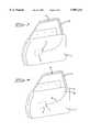
- FIG. 3a configuration in which a piezoelectric cable 4 is caused to extend along a window frame 2 of a vehicle door 1, and is further caused to extend from the window frame 2 to a motor control unit 3 accommodated in the lower part of the door 1 or in the vehicle body (not shown) is shown in FIG. 3; or a configuration in which a connector 5 is attached to the end portion of a piezoelectric cable 4' installed along the window frame 2, and the motor control unit 3 and connector 5 are connected to each other by a separate wire harness 8 which has connectors 6 and 7 installed at both ends is shown in FIG. 4.
- the object of the present inventionis to provide a low-cost piezoelectric cable and wire harness using the same, which offer a high connection reliability without picking up unwanted signals in areas other than the areas where the cable is supposed to act as a sensor.
- the piezoelectric cable of the present inventioncomprises a core conductor, a piezoelectric material layer, an outer conductor and an outer covering disposed in a coaxial configuration in that order from the center outward, a piezoelectric region and a non-piezoelectric region are formed adjacent to each other in the direction of length of the piezoelectric cable.
- the piezoelectric cable of the present inventionincludes a core conductor, a piezoelectric material layer, an outer conductor and an outer covering disposed in a coaxial configuration in that order from the center outward, the piezoelectric material layer is formed as a polarized region and a non-polarized region which are adjacent to each other in the direction of length of the piezoelectric cable.
- the present inventionis directed to a wire harness wherein an electrical connector is attached to an end portion of a non-piezoelectric region or a non-polarized region of a piezoelectric cable.
- a piezoelectric cablecomprises a center conductor, a layer of material covering the center conductor having a piezoelectric region and a non-piezoelectric region; and an outer conductor covering the layer of material.
- a wire harnesscomprises a piezoelectric cable having a center conductor, a layer of material having a piezoelectric region and a non-piezoelectric region covering the center conductor and an outer conductor extending along the layer of material; and an electrical connector attached to the non-piezoelectric region and having electrical contacts respectively connected to the center conductor and the outer conductor.
- FIG. 1is a partly-sectioned view of a piezoelectric cable of the present invention.
- FIG. 2is a perspective view showing a wire harness of the present invention.
- FIG. 3is a side view of a car door containing a conventional wire harness.
- FIG. 4is a side view of a car door containing another conventional wire harness.
- piezoelectric cable 10is constructed from a core or center conductor 12, a layer of piezoelectric material 14, an outer conductor 16 and an outer dielectric covering 18 which are disposed in a coaxial configuration in that order from the center outward.
- the materials of these elementsare basically the same as in a conventional cable.
- the core conductor 12comprises a conductive material such as copper.
- PVDFpolyvinylidene fluoride
- the outer conductor 16is a braided or laterally wound wire comprising a conductive material such as copper
- the outer covering 16is an insulating material such as a polyvinyl chloride (PVC) or polyurethane.
- the piezoelectric cable 10 of the present inventiondiffers from a conventional piezoelectric cable in the following respect: i.e., the cable 10 does not have uniform piezoelectric properties along the entire length of the cable, but instead has a piezoelectric region 20 and a non-piezoelectric region 22 which are adjacent to each other in the direction of the length of the cable. Specifically, the piezoelectric region 20 and non-piezoelectric region 22 are adjacent to each other, with an intermediate section 24 (indicated by a broken line in FIG. 1) as a boundary. Accordingly, when pressure or an impact is applied to the piezoelectric region 20, a pulse voltage is generated between the core conductor 12 and the outer conductor 16; however, no pulse voltage is generated when pressure is applied to the non-piezoelectric region 22.
- a strong electric fieldis applied only to that portion of the piezoelectric material layer 14 in which piezoelectric properties are required, i.e., only to the desired piezoelectric region 20, so that only the piezoelectric material 14 in this piezoelectric region is caused to undergo polarization. Furthermore, since it is difficult to polarize the piezoelectric region 20 of the piezoelectric cable 10 following the completion of the cable, the piezoelectric material layer 14 in the piezoelectric region 20 is polarized prior to the process in which the outer conductor 16 is formed on top of the piezoelectric material layer 14.
- wire harness 30includes a piezoelectric cable 10 in which a piezoelectric region 20 and a non-piezoelectric region 22 form adjacent sections of each other, and an electrical connector 40 which is connected to one end of the non-piezoelectric region 22.
- the electrical connector 40is a universally-known connector comprising an insulating housing 42 which has two contact-accommodating compartments 44 and 46, and two contacts (not shown). The two contacts are respectively connected to the core conductor 12 and the outer conductor 16 of the piezoelectric cable 10.
- the electrical connector 40could also be a universally known coaxial connector or shield connector, or a connector containing circuitry such as an impedance converter circuit, amplifier circuit, comparator circuit and A/D converter circuit for processing signals from the piezoelectric cable 10.
- a connector containing such circuitrythe circuitry in control box or unit 50 described below may be simplified and reduced in size.
- the control box 50 accommodated in the lower portion of the vehicle door 1 or in the vehicle bodyprocesses signals from the piezoelectric cable 10, and sends signals to a motor (not shown) which opens and closes the window.
- Control box 50has an electrical connector 52 which mates with the electrical connector 40.
- the core conductor 12 and outer conductor 16 of the piezoelectric cable 10have a coaxial structure along the entire length of the coaxial cable 10; accordingly, the coaxial cable 10 tends not to be affected by external electromagnetic interference.
- the portion of the piezoelectric cable 10, which is not supposed to act as a sensor as itis of a non-piezoelectric or non-polarized region 22, there is no generation of false signals in this region.
- a weather strip 30made of rubber or the like around the periphery of at least the piezoelectric or polarized region 20 in order to prevent water, etc., from entering the interior of the cable 10.
- the present inventioncan be applied to sensors which detect the passage of vehicles using sensor parts embedded in the roadway (traffic sensors), sensors which are contained in the floor mats of automatic doors and which detect the presence or absence of persons or objects, and sensors which are contained in the mattresses of beds used for medical treatment, and which detect the presence or absence of a patient.
- traffic sensorssensor parts embedded in the roadway
- sensors which are contained in the mattresses of beds used for medical treatmentand which detect the presence or absence of a patient.
- piezoelectric or polarized regions and non-piezoelectric or non-polarized regionsare formed adjacent each other along a piezoelectric cable which has a coaxial structure. Accordingly, the following advantages are obtained: i.e., not only is the cable resistant to electromagnetic interference from the outside, but noise caused by vibration, etc., is not picked up in the regions which are not supposed to act as sensors. Furthermore, since a single piezoelectric cable is used, a high connection reliability is obtained, and production costs can be kept low.
Landscapes
- Engineering & Computer Science (AREA)
- Mechanical Engineering (AREA)
- Window Of Vehicle (AREA)
- Insulated Conductors (AREA)
- Power-Operated Mechanisms For Wings (AREA)
- Push-Button Switches (AREA)
Abstract
Description
Claims (5)
Applications Claiming Priority (2)
| Application Number | Priority Date | Filing Date | Title |
|---|---|---|---|
| JP8-303927 | 1996-10-30 | ||
| JP8303927AJPH10132669A (en) | 1996-10-30 | 1996-10-30 | Piezo cable and wire harness using the same |
Publications (1)
| Publication Number | Publication Date |
|---|---|
| US5907213Atrue US5907213A (en) | 1999-05-25 |
Family
ID=17926960
Family Applications (1)
| Application Number | Title | Priority Date | Filing Date |
|---|---|---|---|
| US08/960,652Expired - Fee RelatedUS5907213A (en) | 1996-10-30 | 1997-10-30 | Piezoelectric cable and wire harness using the same |
Country Status (5)
| Country | Link |
|---|---|
| US (1) | US5907213A (en) |
| JP (1) | JPH10132669A (en) |
| KR (1) | KR19980033312A (en) |
| DE (1) | DE19748076A1 (en) |
| GB (1) | GB2318907B (en) |
Cited By (26)
| Publication number | Priority date | Publication date | Assignee | Title |
|---|---|---|---|---|
| US6169479B1 (en)* | 1998-10-23 | 2001-01-02 | Visteon Global Technologies, Inc. | Vehicular deformation sensor system |
| US6252512B1 (en)* | 1999-03-05 | 2001-06-26 | Hill-Rom, Inc. | Monitoring system and method |
| US20030056600A1 (en)* | 2001-07-09 | 2003-03-27 | Nartron Corporation | Anti-entrapment system |
| EP1096093A3 (en)* | 1999-10-27 | 2004-04-14 | Delphi Technologies, Inc. | Obstruction detection for a window |
| US20040070316A1 (en)* | 2001-10-23 | 2004-04-15 | Achim Neubauer | Device for opening and closing a mobile element |
| US6747399B1 (en) | 1999-05-13 | 2004-06-08 | Matsushita Electric Industrial Co., Ltd. | Pressure-sensitive sensor, object detecting device, and opening-closing device |
| US20040112139A1 (en)* | 2002-12-17 | 2004-06-17 | Matsushita Electric Industrial Co., Ltd. | Pressure sensitive sensor, object detecting device and opening, attachment structure thereof and opening-and-closing device |
| US20050092097A1 (en)* | 2001-07-09 | 2005-05-05 | Nartron Corporation | Anti-entrapment system |
| US6954139B2 (en)* | 2002-07-30 | 2005-10-11 | Matsushita Electric Industrial Co., Ltd. | Contact detecting device |
| US20060117862A1 (en)* | 2004-12-06 | 2006-06-08 | Shank David W | Anti-entrapment system |
| US20060202651A1 (en)* | 2005-03-11 | 2006-09-14 | Washeleski John M | Powered panel moving system |
| US20070007068A1 (en)* | 2005-07-06 | 2007-01-11 | Thomas Weingaertner | Sensor system for a crush protection device |
| US20070022818A1 (en)* | 2005-07-27 | 2007-02-01 | Aisin Seiki Kabushiki Kaisha | Object detecting apparatus |
| US20070089527A1 (en)* | 2001-07-09 | 2007-04-26 | Nartron Corporation | Anti-entrapment system |
| US20070152615A1 (en)* | 2006-01-04 | 2007-07-05 | Nartron Corporation | Vehicle panel control system |
| US20070200692A1 (en)* | 2006-02-24 | 2007-08-30 | Honda Motor Co., Ltd. | Sensor module for vehicle |
| US20080090447A1 (en)* | 2006-10-13 | 2008-04-17 | Lars David Moravy | Wire strain relief structure and method |
| US20110258931A1 (en)* | 2010-04-21 | 2011-10-27 | Gm Global Technology Operations, Inc. | Pinch protection mechanism utilizing active material actuation |
| CN110967109A (en)* | 2019-12-23 | 2020-04-07 | 成都高斯电子技术有限公司 | Sensor preparation liquid and application thereof |
| CN111550146A (en)* | 2019-02-08 | 2020-08-18 | 株式会社城南制作所 | Window regulator |
| US11371896B2 (en)* | 2017-08-09 | 2022-06-28 | Mitsui Chemicals, Inc. | Sensor module containing elongate piezoelectric substrate and pressure distribution sensor provided with the same |
| US11402282B2 (en) | 2015-12-25 | 2022-08-02 | Mitsui Chemicals, Inc. | Piezoelectric substrate, piezoelectric textile, piezoelectric fabric, piezoelectric device, force sensor, actuator, and biological information acquisition device |
| US11545611B2 (en)* | 2019-04-03 | 2023-01-03 | Interface Technology (Chengdu) Co., Ltd. | Piezoelectric hair-like sensor, method for making same, and electronic device using same |
| CN116134203A (en)* | 2020-07-22 | 2023-05-16 | 博泽(班贝格)汽车零部件欧洲两合公司 | Track slider assembly and window lifter for motor vehicle having the same |
| US11723279B2 (en) | 2016-06-06 | 2023-08-08 | Mitsui Chemicals, Inc. | Piezoelectric substrate, piezoelectric woven fabric, piezoelectric knitted fabric, piezoelectric device, force sensor, and actuator |
| US12369879B2 (en) | 2020-05-08 | 2025-07-29 | W. L. Gore & Associates, Inc. | Transcutaneous sound sensor |
Families Citing this family (10)
| Publication number | Priority date | Publication date | Assignee | Title |
|---|---|---|---|---|
| US6337549B1 (en) | 2000-05-12 | 2002-01-08 | Anthony Gerald Bledin | Capacitive anti finger trap proximity sensor |
| JP2004301846A (en)* | 2004-05-06 | 2004-10-28 | Matsushita Electric Ind Co Ltd | Object detection device |
| JP2006243876A (en)* | 2005-03-01 | 2006-09-14 | Toko Electric Corp | Intrusion warning system |
| US20090021112A1 (en)* | 2005-04-14 | 2009-01-22 | Matsushita Electric Industrial Co., Ltd. | Contact detector and door handle unit including it and smart entry system |
| US11647675B2 (en) | 2016-09-27 | 2023-05-09 | Mitsui Chemicals, Inc. | Piezoelectric substrate attachment structure, sensor module, moving body, and protection body |
| CN109716084B (en) | 2016-09-27 | 2021-09-21 | 三井化学株式会社 | Mounting structure of piezoelectric substrate and sensor assembly |
| WO2018092886A1 (en) | 2016-11-18 | 2018-05-24 | 三井化学株式会社 | Piezoelectric base material, sensor, actuator, biological information acquisition device, and piezoelectric fiber structure |
| WO2018194180A1 (en) | 2017-04-20 | 2018-10-25 | 三井化学株式会社 | Piezoelectric base material, force sensor, and actuator |
| EP4202388A4 (en) | 2020-09-25 | 2024-08-28 | Mitsui Chemicals, Inc. | PIEZOELECTRIC DEVICE, FORCE SENSOR AND BIOLOGICAL INFORMATION ACQUISITION DEVICE |
| JP2022157156A (en) | 2021-03-31 | 2022-10-14 | 三井化学株式会社 | Model generation method, computer program, information processing apparatus, information processing system, information processing method, and training data generation method |
Citations (11)
| Publication number | Priority date | Publication date | Assignee | Title |
|---|---|---|---|---|
| US2834943A (en)* | 1953-09-16 | 1958-05-13 | Bell Telephone Labor Inc | Mechanically coupled electromechanical and magnetomechanical transducers |
| US3820208A (en)* | 1971-09-29 | 1974-06-28 | Philips Corp | Method of manufacturing a piezoelectric element |
| US3831162A (en)* | 1973-09-04 | 1974-08-20 | Gte Sylvania Inc | Intrusion detection and location system |
| GB2012519A (en)* | 1978-01-17 | 1979-07-25 | Atomic Energy Authority Uk | Piezoelectric devices |
| US4629925A (en)* | 1983-11-22 | 1986-12-16 | Raychem Corporation | Piezoelectric coaxial cable |
| US4695988A (en)* | 1984-09-12 | 1987-09-22 | Ngk Spark Plug Co. Ltd. | Underwater piezoelectric arrangement |
| GB2256111A (en)* | 1991-04-11 | 1992-11-25 | Univ Southampton | Distributed sensors for active vibration control |
| EP0534532A1 (en)* | 1991-09-25 | 1993-03-31 | Thermocoax | Axle detector built in the surface of a multi-lane road |
| US5275885A (en)* | 1988-12-19 | 1994-01-04 | Ngk Spark Plug Co., Ltd. | Piezoelectric cable |
| US5432498A (en)* | 1992-11-25 | 1995-07-11 | Magal Security Systems, Ltd. | Sensing cable |
| US5486820A (en)* | 1992-12-18 | 1996-01-23 | The Whitaker Corporation | Traffic sensor having piezoelectric sensors which distinguish lanes |
- 1996
- 1996-10-30JPJP8303927Apatent/JPH10132669A/enactivePending
- 1997
- 1997-10-29GBGB9722857Apatent/GB2318907B/ennot_activeExpired - Fee Related
- 1997-10-30DEDE19748076Apatent/DE19748076A1/ennot_activeWithdrawn
- 1997-10-30USUS08/960,652patent/US5907213A/ennot_activeExpired - Fee Related
- 1997-10-30KRKR1019970056298Apatent/KR19980033312A/ennot_activeWithdrawn
Patent Citations (11)
| Publication number | Priority date | Publication date | Assignee | Title |
|---|---|---|---|---|
| US2834943A (en)* | 1953-09-16 | 1958-05-13 | Bell Telephone Labor Inc | Mechanically coupled electromechanical and magnetomechanical transducers |
| US3820208A (en)* | 1971-09-29 | 1974-06-28 | Philips Corp | Method of manufacturing a piezoelectric element |
| US3831162A (en)* | 1973-09-04 | 1974-08-20 | Gte Sylvania Inc | Intrusion detection and location system |
| GB2012519A (en)* | 1978-01-17 | 1979-07-25 | Atomic Energy Authority Uk | Piezoelectric devices |
| US4629925A (en)* | 1983-11-22 | 1986-12-16 | Raychem Corporation | Piezoelectric coaxial cable |
| US4695988A (en)* | 1984-09-12 | 1987-09-22 | Ngk Spark Plug Co. Ltd. | Underwater piezoelectric arrangement |
| US5275885A (en)* | 1988-12-19 | 1994-01-04 | Ngk Spark Plug Co., Ltd. | Piezoelectric cable |
| GB2256111A (en)* | 1991-04-11 | 1992-11-25 | Univ Southampton | Distributed sensors for active vibration control |
| EP0534532A1 (en)* | 1991-09-25 | 1993-03-31 | Thermocoax | Axle detector built in the surface of a multi-lane road |
| US5432498A (en)* | 1992-11-25 | 1995-07-11 | Magal Security Systems, Ltd. | Sensing cable |
| US5486820A (en)* | 1992-12-18 | 1996-01-23 | The Whitaker Corporation | Traffic sensor having piezoelectric sensors which distinguish lanes |
Non-Patent Citations (1)
| Title |
|---|
| United Kingdom Search Report, dated Feb. 9, 1998.* |
Cited By (55)
| Publication number | Priority date | Publication date | Assignee | Title |
|---|---|---|---|---|
| US6169479B1 (en)* | 1998-10-23 | 2001-01-02 | Visteon Global Technologies, Inc. | Vehicular deformation sensor system |
| US6819254B2 (en) | 1999-03-05 | 2004-11-16 | Hill-Rom Services, Inc. | Monitoring system and method |
| US6252512B1 (en)* | 1999-03-05 | 2001-06-26 | Hill-Rom, Inc. | Monitoring system and method |
| US20050166680A1 (en)* | 1999-05-13 | 2005-08-04 | Hiroyuki Ogino | Pressure-sensitive sensor, object detecting device, and opening-closing device |
| US20040195940A1 (en)* | 1999-05-13 | 2004-10-07 | Hiroyuki Ogino | Pressure-sensitive sensor, object detecting device, and opening-closing device |
| US6951140B2 (en)* | 1999-05-13 | 2005-10-04 | Matsushita Electric Industrial Co., Ltd. | Pressure-sensitive sensor, object detecting device, and opening-closing device |
| US6747399B1 (en) | 1999-05-13 | 2004-06-08 | Matsushita Electric Industrial Co., Ltd. | Pressure-sensitive sensor, object detecting device, and opening-closing device |
| US7174790B2 (en)* | 1999-05-13 | 2007-02-13 | Matsushita Electric Industrial Co., Ltd. | Pressure-sensitive sensor, object detecting device, and opening-closing device |
| EP1096093A3 (en)* | 1999-10-27 | 2004-04-14 | Delphi Technologies, Inc. | Obstruction detection for a window |
| US6782759B2 (en) | 2001-07-09 | 2004-08-31 | Nartron Corporation | Anti-entrapment system |
| US7293467B2 (en) | 2001-07-09 | 2007-11-13 | Nartron Corporation | Anti-entrapment system |
| US20050016290A1 (en)* | 2001-07-09 | 2005-01-27 | Nartron Corporation | Anti-entrapment system |
| US20030056600A1 (en)* | 2001-07-09 | 2003-03-27 | Nartron Corporation | Anti-entrapment system |
| US20050092097A1 (en)* | 2001-07-09 | 2005-05-05 | Nartron Corporation | Anti-entrapment system |
| US7132642B2 (en) | 2001-07-09 | 2006-11-07 | Nartron Corporation | Anti-entrapment systems for preventing objects from being entrapped by translating devices |
| US7513166B2 (en) | 2001-07-09 | 2009-04-07 | Nartron Corporation | Anti-entrapment system |
| US20070089527A1 (en)* | 2001-07-09 | 2007-04-26 | Nartron Corporation | Anti-entrapment system |
| US6968746B2 (en) | 2001-07-09 | 2005-11-29 | Nartron Corporation | Anti-entrapment system |
| US20040070316A1 (en)* | 2001-10-23 | 2004-04-15 | Achim Neubauer | Device for opening and closing a mobile element |
| US7362040B2 (en)* | 2001-10-23 | 2008-04-22 | Robert Bosch Gmbh | Device for opening and closing a mobile element |
| US6954139B2 (en)* | 2002-07-30 | 2005-10-11 | Matsushita Electric Industrial Co., Ltd. | Contact detecting device |
| CN1309100C (en)* | 2002-07-30 | 2007-04-04 | 松下电器产业株式会社 | Contact detecting device |
| WO2004031520A1 (en)* | 2002-09-30 | 2004-04-15 | Nartron Corporation | Anti-entrapment system |
| US6883382B2 (en)* | 2002-12-17 | 2005-04-26 | Matsushita Electric Industrial Co., Inc. | Pressure sensitive sensor, object detecting device and opening, attachment structure thereof and opening-and-closing device |
| US20040112139A1 (en)* | 2002-12-17 | 2004-06-17 | Matsushita Electric Industrial Co., Ltd. | Pressure sensitive sensor, object detecting device and opening, attachment structure thereof and opening-and-closing device |
| US7165457B2 (en) | 2002-12-17 | 2007-01-23 | Matsushita Electric Industrial Co., Ltd. | Pressure sensitive sensor, object detecting device and opening, attachment structure thereof and opening-and-closing device |
| US20050103117A1 (en)* | 2002-12-17 | 2005-05-19 | Matsushita Electric Industrial Co., Ltd. | Pressure sensitive sensor, object detecting device and opening, attachment structure thereof and opening-and-closing device |
| US20060117862A1 (en)* | 2004-12-06 | 2006-06-08 | Shank David W | Anti-entrapment system |
| US7162928B2 (en) | 2004-12-06 | 2007-01-16 | Nartron Corporation | Anti-entrapment system |
| US7449852B2 (en) | 2005-03-11 | 2008-11-11 | Nartron Corporation | Powered panel moving system |
| US7312591B2 (en) | 2005-03-11 | 2007-12-25 | Npc Corporation | Powered panel moving system |
| US20060202651A1 (en)* | 2005-03-11 | 2006-09-14 | Washeleski John M | Powered panel moving system |
| US20070007068A1 (en)* | 2005-07-06 | 2007-01-11 | Thomas Weingaertner | Sensor system for a crush protection device |
| US7330007B2 (en)* | 2005-07-27 | 2008-02-12 | Aisin Seiki Kabushiki Kaisha | Object detecting apparatus |
| US20070022818A1 (en)* | 2005-07-27 | 2007-02-01 | Aisin Seiki Kabushiki Kaisha | Object detecting apparatus |
| US20070152615A1 (en)* | 2006-01-04 | 2007-07-05 | Nartron Corporation | Vehicle panel control system |
| US7342373B2 (en) | 2006-01-04 | 2008-03-11 | Nartron Corporation | Vehicle panel control system |
| US20080136358A1 (en)* | 2006-01-04 | 2008-06-12 | Nartron Corporation | Vehicle panel control system |
| US7518327B2 (en) | 2006-01-04 | 2009-04-14 | Nartron Corporation | Vehicle panel control system |
| US20070200692A1 (en)* | 2006-02-24 | 2007-08-30 | Honda Motor Co., Ltd. | Sensor module for vehicle |
| US7575086B2 (en)* | 2006-02-24 | 2009-08-18 | Honda Motor Co., Ltd. | Sensor module for vehicle |
| US20080090447A1 (en)* | 2006-10-13 | 2008-04-17 | Lars David Moravy | Wire strain relief structure and method |
| US20110258931A1 (en)* | 2010-04-21 | 2011-10-27 | Gm Global Technology Operations, Inc. | Pinch protection mechanism utilizing active material actuation |
| US8627600B2 (en)* | 2010-04-21 | 2014-01-14 | GM Global Technology Operations LLC | Pinch protection mechanism utilizing active material actuation |
| US11402282B2 (en) | 2015-12-25 | 2022-08-02 | Mitsui Chemicals, Inc. | Piezoelectric substrate, piezoelectric textile, piezoelectric fabric, piezoelectric device, force sensor, actuator, and biological information acquisition device |
| US11723279B2 (en) | 2016-06-06 | 2023-08-08 | Mitsui Chemicals, Inc. | Piezoelectric substrate, piezoelectric woven fabric, piezoelectric knitted fabric, piezoelectric device, force sensor, and actuator |
| US11371896B2 (en)* | 2017-08-09 | 2022-06-28 | Mitsui Chemicals, Inc. | Sensor module containing elongate piezoelectric substrate and pressure distribution sensor provided with the same |
| CN111550146A (en)* | 2019-02-08 | 2020-08-18 | 株式会社城南制作所 | Window regulator |
| CN111550146B (en)* | 2019-02-08 | 2021-11-19 | 株式会社城南制作所 | Window regulator |
| US11545611B2 (en)* | 2019-04-03 | 2023-01-03 | Interface Technology (Chengdu) Co., Ltd. | Piezoelectric hair-like sensor, method for making same, and electronic device using same |
| CN110967109A (en)* | 2019-12-23 | 2020-04-07 | 成都高斯电子技术有限公司 | Sensor preparation liquid and application thereof |
| CN110967109B (en)* | 2019-12-23 | 2022-04-01 | 成都高斯电子技术有限公司 | Sensor preparation liquid and application thereof |
| US12369879B2 (en) | 2020-05-08 | 2025-07-29 | W. L. Gore & Associates, Inc. | Transcutaneous sound sensor |
| CN116134203A (en)* | 2020-07-22 | 2023-05-16 | 博泽(班贝格)汽车零部件欧洲两合公司 | Track slider assembly and window lifter for motor vehicle having the same |
| US12378808B2 (en) | 2020-07-22 | 2025-08-05 | Brose Fahrzeugteile Se & Co. Kommanditgesellschaft, Bamberg | Rail-slider assembly and window lifter of a motor vehicle having such an assembly |
Also Published As
| Publication number | Publication date |
|---|---|
| KR19980033312A (en) | 1998-07-25 |
| GB2318907A (en) | 1998-05-06 |
| GB9722857D0 (en) | 1997-12-24 |
| JPH10132669A (en) | 1998-05-22 |
| DE19748076A1 (en) | 1998-05-07 |
| GB2318907B (en) | 2000-11-29 |
Similar Documents
| Publication | Publication Date | Title |
|---|---|---|
| US5907213A (en) | Piezoelectric cable and wire harness using the same | |
| US11077806B2 (en) | Complex harness | |
| JP4504904B2 (en) | Code switch and detection device using the same | |
| KR100613534B1 (en) | Pressure Sensing Sensor, Object Detection Device, and Switchgear | |
| US7436315B2 (en) | Passenger detection system | |
| US8191311B2 (en) | Opening and closing apparatus | |
| US20040112139A1 (en) | Pressure sensitive sensor, object detecting device and opening, attachment structure thereof and opening-and-closing device | |
| CN103328753A (en) | Sensor unit for remotely actuating a vehicle door | |
| US5728983A (en) | Elongated tube-like pressure sensitive cable switch | |
| US20060131915A1 (en) | Pinch detection device and opening/closing device | |
| US20100006407A1 (en) | Pressure detection switch and opening/closing apparatus for vehicle | |
| US20060113172A1 (en) | Pressure sensor, object detection device, opening/closing device, and method for producing the pressure sensor | |
| US6962228B2 (en) | Contact detecting device and vehicle mounting the same | |
| US20060152375A1 (en) | Pressure-sensitive sensor and object detector | |
| CN212098388U (en) | Make things convenient for wire management and install stable car and prevent pressing from both sides strip | |
| CN212098387U (en) | Anti-pinch strip for automobile | |
| GB2300732A (en) | Window sealing system with piezo-electric cable anti-trap sensor | |
| CN114008429A (en) | Anti-pinch sensor with quick connect feature and method of connecting it to wire harness | |
| JP3740947B2 (en) | Pinch detection device and switching device | |
| JP2001167663A5 (en) | ||
| US20240060347A1 (en) | Finger protection section with integrated switching system | |
| JP2004219289A (en) | Connection type pressure sensor and switchgear | |
| JP2001165784A (en) | Entrapment detection device and switchgear | |
| JP2010140768A (en) | Sensor holder and touch sensor | |
| JP2001165784A5 (en) |
Legal Events
| Date | Code | Title | Description |
|---|---|---|---|
| AS | Assignment | Owner name:AMP SENSORS LTD., PENNSYLVANIA Free format text:ASSIGNMENT OF ASSIGNORS INTEREST;ASSIGNOR:PARK, KYUNG TAE;REEL/FRAME:008801/0439 Effective date:19970818 Owner name:AMP TECHNOLOGY JAPAN, LTD., JAPAN Free format text:ASSIGNMENT OF ASSIGNORS INTEREST;ASSIGNORS:OSHIMA, RYUICHI;NAITO, TAKAKI;REEL/FRAME:008801/0436 Effective date:19970731 Owner name:WHITAKER CORPORATION, THE, DELAWARE Free format text:ASSIGNMENT OF ASSIGNORS INTEREST;ASSIGNOR:AMP SENSORS LTD.;REEL/FRAME:008801/0446 Effective date:19971029 Owner name:WHITAKER CORPORATION, THE, DELAWARE Free format text:ASSIGNMENT OF ASSIGNORS INTEREST;ASSIGNOR:AMP TECHNOLOGY JAPAN, LTD.;REEL/FRAME:008801/0462 Effective date:19971029 | |
| AS | Assignment | Owner name:PNC BANK, NATIONAL ASSOCIATION, NEW JERSEY Free format text:SECURITY INTEREST;ASSIGNOR:MEASUREMENT SPECIALTIES, INC.;REEL/FRAME:009580/0587 Effective date:19980812 | |
| AS | Assignment | Owner name:PNC BANK, NATIONAL ASSOCIATION, NEW JERSEY Free format text:SECURITY INTEREST;ASSIGNOR:MEASUREMENT SPECIALTIES, INC.;REEL/FRAME:010756/0832 Effective date:20000215 | |
| AS | Assignment | Owner name:FIRST UNION NATIONAL BANK, AS AGENT, NEW JERSEY Free format text:SECURITY AGREEMENT;ASSIGNOR:MEASUREMENT SPECIALITIES, INC.;REEL/FRAME:011231/0619 Effective date:20000807 | |
| REMI | Maintenance fee reminder mailed | ||
| AS | Assignment | Owner name:IC SENSORS, INC., NEW JERSEY Free format text:RELEASE OF SECURITY INTEREST IN PATENTS AND TRADEM;ASSIGNOR:WACHOVIA BANK, NATIONAL ASSOCIATION;REEL/FRAME:013879/0721 Effective date:20030130 Owner name:MEASUREMENTSPECIALTIES, INC., NEW JERSEY Free format text:RELEASE OF SECURITY INTEREST IN PATENTS AND TRADEM;ASSIGNOR:WACHOVIA BANK, NATIONAL ASSOCIATION;REEL/FRAME:013879/0721 Effective date:20030130 | |
| LAPS | Lapse for failure to pay maintenance fees | ||
| STCH | Information on status: patent discontinuation | Free format text:PATENT EXPIRED DUE TO NONPAYMENT OF MAINTENANCE FEES UNDER 37 CFR 1.362 | |
| FP | Lapsed due to failure to pay maintenance fee | Effective date:20030525 | |
| AS | Assignment | Owner name:GENERAL ELECTRIC CAPITAL CORPORATION, CONNECTICUT Free format text:SECURITY AGREEMENT;ASSIGNOR:MEASUREMENT SPECIALTIES, INC.;REEL/FRAME:016153/0714 Effective date:20041217 | |
| AS | Assignment | Owner name:MEASUREMENT SPECIALTIES, INC.,VIRGINIA Free format text:RELEASE BY SECURED PARTY;ASSIGNOR:GENERAL ELECTRIC CAPITAL CORPORATION;REEL/FRAME:024474/0377 Effective date:20100601 Owner name:IC SENSORS, INC.,VIRGINIA Free format text:RELEASE BY SECURED PARTY;ASSIGNOR:GENERAL ELECTRIC CAPITAL CORPORATION;REEL/FRAME:024474/0377 Effective date:20100601 Owner name:ELEKON INDUSTRIES USA, INC.,VIRGINIA Free format text:RELEASE BY SECURED PARTY;ASSIGNOR:GENERAL ELECTRIC CAPITAL CORPORATION;REEL/FRAME:024474/0377 Effective date:20100601 Owner name:ENTRAN DEVICES LLC,VIRGINIA Free format text:RELEASE BY SECURED PARTY;ASSIGNOR:GENERAL ELECTRIC CAPITAL CORPORATION;REEL/FRAME:024474/0377 Effective date:20100601 Owner name:MEASUREMENT SPECIALTIES FOREIGN HOLDINGS CORPORATI Free format text:RELEASE BY SECURED PARTY;ASSIGNOR:GENERAL ELECTRIC CAPITAL CORPORATION;REEL/FRAME:024474/0377 Effective date:20100601 Owner name:YSIS INCORPORATED,VIRGINIA Free format text:RELEASE BY SECURED PARTY;ASSIGNOR:GENERAL ELECTRIC CAPITAL CORPORATION;REEL/FRAME:024474/0377 Effective date:20100601 Owner name:MREHTATEB, LLC LIMITED LIABILITY COMPANY - MASSACH Free format text:RELEASE BY SECURED PARTY;ASSIGNOR:GENERAL ELECTRIC CAPITAL CORPORATION;REEL/FRAME:024474/0377 Effective date:20100601 | |
| AS | Assignment | Owner name:MEASUREMENT SPECIALITIES, NEW JERSEY Free format text:PATENTS RELEASE;ASSIGNOR:PNC BANK, NATIONAL ASSOCIATION;REEL/FRAME:026583/0289 Effective date:20110329 |