US5906758A - Plasma arc torch - Google Patents
Plasma arc torchDownload PDFInfo
- Publication number
- US5906758A US5906758AUS08/940,678US94067897AUS5906758AUS 5906758 AUS5906758 AUS 5906758AUS 94067897 AUS94067897 AUS 94067897AUS 5906758 AUS5906758 AUS 5906758A
- Authority
- US
- United States
- Prior art keywords
- nozzle
- sleeve
- metal insert
- plasma arc
- torch
- Prior art date
- Legal status (The legal status is an assumption and is not a legal conclusion. Google has not performed a legal analysis and makes no representation as to the accuracy of the status listed.)
- Expired - Lifetime
Links
Images


Classifications
- H—ELECTRICITY
- H05—ELECTRIC TECHNIQUES NOT OTHERWISE PROVIDED FOR
- H05H—PLASMA TECHNIQUE; PRODUCTION OF ACCELERATED ELECTRICALLY-CHARGED PARTICLES OR OF NEUTRONS; PRODUCTION OR ACCELERATION OF NEUTRAL MOLECULAR OR ATOMIC BEAMS
- H05H1/00—Generating plasma; Handling plasma
- H05H1/24—Generating plasma
- H05H1/26—Plasma torches
- H05H1/32—Plasma torches using an arc
- H05H1/34—Details, e.g. electrodes, nozzles
- H05H1/3436—Hollow cathodes with internal coolant flow
- H—ELECTRICITY
- H05—ELECTRIC TECHNIQUES NOT OTHERWISE PROVIDED FOR
- H05H—PLASMA TECHNIQUE; PRODUCTION OF ACCELERATED ELECTRICALLY-CHARGED PARTICLES OR OF NEUTRONS; PRODUCTION OR ACCELERATION OF NEUTRAL MOLECULAR OR ATOMIC BEAMS
- H05H1/00—Generating plasma; Handling plasma
- H05H1/24—Generating plasma
- H05H1/26—Plasma torches
- H05H1/32—Plasma torches using an arc
- H05H1/34—Details, e.g. electrodes, nozzles
- H05H1/3442—Cathodes with inserted tip
Definitions
- the present inventionrelates to a plasma arc torch of the type commonly used to cut or weld a metal workpiece.
- U.S. Pat. No. 5,393,952discloses a plasma arc torch having a water cooled electrode, and a nozzle positioned to form a plasma gas passage between the electrode and the nozzle and leading to a nozzle discharge opening immediately below the electrode.
- the nozzleis mounted on a gas swirl baffle which is interposed between the electrode and the nozzle.
- a nozzle capcovers the nozzle, and an outer shield surrounds the nozzle cap so as to define a shielding gas passage which exits about the discharge opening of the nozzle.
- a plasma arc torchwhich comprises an upper body member having a depending sleeve which defines a central axis, and an electrode holder mounted within the depending sleeve and extending axially therefrom to a distal end.
- An electrodeis mounted at the distal end of the electrode holder.
- a sleeve assemblyis joined to the upper body member and surrounds the depending sleeve and extends axially to a tubular lower end, and a nozzle coaxially surrounds the electrode in a spaced-apart relation to define a space therebetween.
- the nozzleincludes a cylindrical portion disposed within the tubular lower end of the sleeve assembly with an interengaging fit, which serves to concentrically locate the nozzle with respect to the electrode and the other torch components.
- the nozzlefurther includes a discharge opening which is coaxially aligned below the nozzle and a shoulder which directly engages the lower end of the sleeve assembly, with the engagement between the shoulder and the lower end of the sleeve assembly serving to accurately locate the nozzle longitudinally with respect to the electrode and the other torch components.
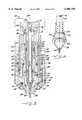
- FIG. 1is a sectional side elevation view of a plasma arc torch which embodies the features of the present invention
- FIG. 2is a sectional view taken substantially along the line 2--2 of FIG. 1;
- FIG. 3is a perspective view of the upper body member of the torch shown in FIGS. 1 and 2;
- FIG. 4is a fragmentary enlarged sectional view illustrating the helical threads on the outside of the depending sleeve of the upper body member and taken substantially along the line 4--4 of FIG. 3;
- FIG. 5is a fragmentary perspective view of the electrode holder and nozzle of the torch
- FIG. 6is an exploded sectional view similar to FIG. 1;
- FIG. 7is a sectional view taken substantially along the line 7--7 of FIG. 6.
- a plasma arc torchwhich embodies the present invention is indicated generally at 10.
- the torch 10comprises an upper body member 12 which is preferably made of brass and which includes an integral depending sleeve 13.
- the interior of the sleeve 13forms a part of an internal vertical bore 14 in the upper body member, which coaxially receives an elongate tubular brass baffle 16 which is threadedly joined in the bore at 17.
- a tubular brass electrode holder 18is coaxially disposed on the outside of the baffle, and the holder is threadedly joined in the bore 14 at 20.
- a cup shaped electrode 22 of the type disclosed, for example, in U.S. Pat. No. 5,023,425,is joined at the lower end of the holder.
- the bore 14 of the upper body membercommunicates with a radial passage 24, which is connected to a coolant (water) supply line 25, whereby cooling water is supplied to the passage 24 which then flows downwardly through the interior of the baffle 16 to the electrode 22. From the electrode, the cooling water flows upwardly between the baffle 16 and the holder 18 to a second radial passage 26 in the upper body member which is connected to a jumper hose 28 (FIGS. 6 and 7).
- the exterior surface of the depending sleeve 13 of the upper body member 12includes a relatively coarse helical thread 30 for the purposes described below.
- a plastic tubular insulator sleeve 32is coaxially joined to the upper body member so as to surround the depending sleeve 13 and extend downwardly therebeyond.
- the upper body member 12includes a radial passage 34 (FIG. 2) which is connected to a cutting or plasma gas delivery line 35, and the radial passage 34 communicates with an axial bore 36 which in turn communicates with the space between the outside of the depending sleeve 13 and the tubular insulator sleeve 32.
- the plasma torch 10further includes a tubular stainless steel insert 38 which is coaxially fit onto the outside of the insulator sleeve 32, and a brass outer sleeve 40 is coaxially fit onto the outside of the metal insert 38.
- the brass outer sleeve 40has an internal bore of oval outline when viewed in cross section, so as to define two vertical side passages 41, 42 between the metal insert 38 and the brass outer sleeve 40, as best seen in FIG. 2.
- the upper end of the side passage 41is joined via a radial bore 44 to the jumper hose 28 so that the cooling water flows into the side passage 41.
- the upper portion of the side passage 42is joined via a radial bore 45 in the outer sleeve 40 with the coolant outlet line 46.
- a flow switch 47(FIG. 6) is positioned in the outlet line 46 for the purpose described below.
- a nozzle 50is joined by an interengaging or press fit into the inside bore of the metal insert 38. More particularly, the nozzle 50 comprises a body member composed of an annular wall which defines a central axis and which includes a cylindrical external portion 52 which is received concentrically in the inside bore of the metal insert 38. A groove 53 in the cylindrical external portion accommodates a sealing O-ring 54. Also an upper shoulder 55 extends radially outwardly at one end of the cylindrical external portion, which engages the end of the metal insert 38. A second shoulder 56 faces downwardly, and engages a retaining member as further described below. A sealing O-ring 57 is disposed about the annular body adjacent the second shoulder.
- the annular wall of the nozzlefurther comprises a frusto conical lower end portion 59, which terminates in an outlet or discharge opening 60 which is coaxially aligned below the electrode 22.
- the press fit mounting of the cylindrical external portion 52 of the nozzle 50 in the inside diameter of the tubular metal insert 38insures the concentric alignment of the nozzle with the electrode 22 and the other torch components. Also, the abutting engagement between the shoulder 55 and the end of the metal insert 38 insures the desired longitudinal alignment of the nozzle.
- a tubular ceramic insulator 62is disposed between the metal insert 38 and the electrode holder 18, and the insulator 62 includes an upper sleeve portion 63 which extends into the lower end of the plastic insulator sleeve 32. Also, the ceramic insulator 62 includes an external shoulder which supports a sealing O-ring 65.
- a plastic tubular insulator 68is mounted coaxially about the outside of the outer sleeve 40 of the torch, and the insulator 68 includes a groove which mounts a sealing O-ring 70 as further described below.
- a heat shield assembly 72is threadedly joined to the lower end of the outer sleeve 40, and retains the nozzle 50 in its operative position on the metal insert 38.
- the heat shield assembly 72includes an annular brass insert 74 which is threadedly connected to the lower end portion of the outer sleeve 40.
- a non-metallic plastic jacket 76surrounds the outside of the insert 74, with the insert 74 and the jacket 76 being joined to each other by means of an interengaging fit therebetween.
- the insert 74includes an internal shoulder 77, which is positioned to engage the shoulder 56 of the nozzle and thereby retain the nozzle in its operative position.
- the sealing O-ring 57is positioned to form a seal between the two shoulders 56 and 77.
- the heat shield assembly 72may further include an annular metal guard 78 which is joined to the outside of the non-metallic jacket 76 by a press fit.
- the exterior surface of the insert 74includes a plurality of vertical splines, which define vertical gas passages 80 between the exterior surface of the insert 74 and the internal surface of the jacket 76, for the purpose described below. Also, and as best seen in FIG. 2, the insert 74 forms a communicating water passage between the side passage 41 and the side passage 42, and thus the cooling water is able to directly contact and cool the exterior surface of the nozzle 50.
- the upper end of the jacket 76overlies the lower portion of the plastic tubular insulator 68, and the O-ring 70 acts to provide a seal therebetween, which seals the shield gas flow path as further described below.
- An inlet line 82 for the shielding gasconnects to the outer sleeve 40, and an axially extending internal passage 83 (FIG. 1) in the outer sleeve 40 connects the inlet line 82 to the vertical gas passages 80 between the insert 74 and the jacket 76 of the heat shield assembly.
- the cooling waterenters the torch through the line 25 and passes downwardly through the interior of the baffle 16 to the inside of the cup shaped electrode 22. From the electrode, the water flows upwardly along the outside of the baffle 16 and exits via the passage 26 to the jumper hose 28.
- the jumper hose 28connects via the bore 44 in the outer sleeve 40 to the side passage 41, and the jumper hose thus provides a water path from the upper body member to the outer sleeve 40, while breaking the electrical path.
- the waterflows downwardly to the space surrounding the nozzle 50 defined by the insert 74 of the heat shield assembly 72, and so as to cool the nozzle.
- the waterthen flows upwardly through the side passage 42 to the water outlet line 46 via the bore 45.
- the cutting or plasma gasflows into the passage 34 in the body member 12 via the line 35, and it then flows downwardly through the annular space between the depending sleeve 13 of the upper body member and the plastic insulator sleeve 32.
- the relatively course threads 30 on the depending sleeveimpart a swirling motion to the entering gas, which continues as the gas moves downwardly past the electrode 22 and out from the discharge opening 60 in the nozzle 50.
- the desired swirling motionis achieved without the use of a separate swirl ring immediately adjacent the nozzle, as is conventional.
- the shield gasenters the outer sleeve 40 via the line 82, and it passes downwardly through the passage 83 to the heat shield assembly 72.
- the shield gasthen passes downwardly through the gas passages 80 formed between the insert 74 and the jacket 76, and the gas then flows outwardly along the outside of the frusto conical nose portion 59 of the nozzle.
- the three components of the heat shield assembly 72are press fit together, and they are thereby removable as a unit by unthreading the unit from the outer sleeve 40 of the torch. Upon such removal, the water path is broken, and the flow switch 47 opens to thereby terminate operation of the torch. This safety feature minimizes the risk of accidental electrical shock by contacting the internal components of the torch while it is electrically connected.
- the nozzle 50When the heat shield assembly 72 is removed, the nozzle 50 may be axially withdrawn from the metal insert 38, and the electrode 22 and electrode holder 18 then may be unthreaded and removed.
- the baffle 16may then also be easily removed by unthreading. Thus these several components of the torch may be easily removed and repaired or replaced as necessary.
Landscapes
- Physics & Mathematics (AREA)
- Engineering & Computer Science (AREA)
- Plasma & Fusion (AREA)
- Spectroscopy & Molecular Physics (AREA)
- Plasma Technology (AREA)
- Arc Welding In General (AREA)
Abstract
Description
Claims (16)
Priority Applications (1)
| Application Number | Priority Date | Filing Date | Title |
|---|---|---|---|
| US08/940,678US5906758A (en) | 1997-09-30 | 1997-09-30 | Plasma arc torch |
Applications Claiming Priority (1)
| Application Number | Priority Date | Filing Date | Title |
|---|---|---|---|
| US08/940,678US5906758A (en) | 1997-09-30 | 1997-09-30 | Plasma arc torch |
Publications (1)
| Publication Number | Publication Date |
|---|---|
| US5906758Atrue US5906758A (en) | 1999-05-25 |
Family
ID=25475241
Family Applications (1)
| Application Number | Title | Priority Date | Filing Date |
|---|---|---|---|
| US08/940,678Expired - LifetimeUS5906758A (en) | 1997-09-30 | 1997-09-30 | Plasma arc torch |
Country Status (1)
| Country | Link |
|---|---|
| US (1) | US5906758A (en) |
Cited By (25)
| Publication number | Priority date | Publication date | Assignee | Title |
|---|---|---|---|---|
| US20030209525A1 (en)* | 2002-05-09 | 2003-11-13 | American Torch Tip: | Electrodes and nozzles having improved connection and quick release |
| US20030213782A1 (en)* | 2002-04-19 | 2003-11-20 | Mackenzie Darrin H. | Plasma arc torch |
| US6667459B1 (en) | 2000-11-21 | 2003-12-23 | Hypertherm, Inc. | Configurable nozzle baffle apparatus and method |
| US6703581B2 (en) | 2001-02-27 | 2004-03-09 | Thermal Dynamics Corporation | Contact start plasma torch |
| US20040200810A1 (en)* | 2003-04-11 | 2004-10-14 | Hypertherm, Inc. | Method and apparatus for alignment of components of a plasma arc torch |
| US20040200809A1 (en)* | 2003-04-07 | 2004-10-14 | Mackenzie Darrin H. | Retractable electrode coolant tube |
| USD498246S1 (en) | 2003-10-01 | 2004-11-09 | Tatras, Inc. | Fitting for plasma ARC torch |
| US20040256365A1 (en)* | 2003-06-20 | 2004-12-23 | Depetrillo Albert R. | Modular icp torch assembly |
| US6841754B2 (en) | 2001-03-09 | 2005-01-11 | Hypertherm, Inc. | Composite electrode for a plasma arc torch |
| GB2363957B (en)* | 2000-06-21 | 2005-04-13 | Inocon Technologie Gmbh | Plasma torch apparatus |
| US20050115932A1 (en)* | 2000-07-10 | 2005-06-02 | Deegan David E. | Method of improving the service life of a plasma torch electrode |
| RU2263564C1 (en)* | 2004-03-22 | 2005-11-10 | Пенкин Станислав Петрович | Steam plasmotron |
| US20060289396A1 (en)* | 2005-04-19 | 2006-12-28 | Zheng Duan | Apparatus for cooling plasma arc torch nozzles |
| US20070045241A1 (en)* | 2005-08-29 | 2007-03-01 | Schneider Joseph C | Contact start plasma torch and method of operation |
| US20080116179A1 (en)* | 2003-04-11 | 2008-05-22 | Hypertherm, Inc. | Method and apparatus for alignment of components of a plasma arc torch |
| US8921731B2 (en) | 2009-08-11 | 2014-12-30 | Kjellberg Finsterwalde Plasma Und Maschinen Gmbh | Protective nozzle cap, protective nozzle cap retainer, and arc plasma torch having said protective nozzle cap and or said protective nozzle cap retainer |
| US20150334818A1 (en)* | 2014-05-19 | 2015-11-19 | Lincoln Global, Inc. | Air cooled plasma torch and components thereof |
| US9279722B2 (en) | 2012-04-30 | 2016-03-08 | Agilent Technologies, Inc. | Optical emission system including dichroic beam combiner |
| US20160074973A1 (en)* | 2014-09-15 | 2016-03-17 | Lincoln Global, Inc. | Electric arc torch with cooling conduit |
| US20160120014A1 (en)* | 2013-05-16 | 2016-04-28 | Kjellberg-Stiftung | Single or multi-part insulating component for a plasma torch, particularly a plasma cutting torch, and assemblies and plasma torches having the same |
| US20170182585A1 (en)* | 2015-01-30 | 2017-06-29 | Komatsu Industries Corporation | Center pipe for plasma torch, contact piece electrode, and plasma torch |
| CN108127236A (en)* | 2018-02-05 | 2018-06-08 | 常州九圣焊割设备有限公司 | High efficiency and heat radiation formula plasma arc cutting torch |
| EP3616825A1 (en)* | 2018-09-03 | 2020-03-04 | Linde Aktiengesellschaft | Cryo cooling of gas cooled plasma arc torches |
| US20220192001A1 (en)* | 2020-12-15 | 2022-06-16 | Lincoln Global, Inc. | Plasma arc torch and cutting system |
| CN118492586A (en)* | 2024-07-19 | 2024-08-16 | 洛阳伍鑫金属材料科技有限公司 | Plasma arc welding equipment for titanium alloy pipeline |
Citations (14)
| Publication number | Priority date | Publication date | Assignee | Title |
|---|---|---|---|---|
| US4282418A (en)* | 1978-09-11 | 1981-08-04 | Siemens Aktiengesellschaft | Plasma torch for micro-plasma welding |
| US4389559A (en)* | 1981-01-28 | 1983-06-21 | Eutectic Corporation | Plasma-transferred-arc torch construction |
| US4521666A (en)* | 1982-12-23 | 1985-06-04 | Union Carbide Corporation | Plasma arc torch |
| US4902871A (en)* | 1987-01-30 | 1990-02-20 | Hypertherm, Inc. | Apparatus and process for cooling a plasma arc electrode |
| US4973816A (en)* | 1989-03-28 | 1990-11-27 | Delaware Capital Formation, Inc. | Plasma torch with safety switch |
| JPH038872A (en)* | 1989-06-02 | 1991-01-16 | Kuraray Co Ltd | Production of electrically conductive fiber |
| US5023425A (en)* | 1990-01-17 | 1991-06-11 | Esab Welding Products, Inc. | Electrode for plasma arc torch and method of fabricating same |
| US5124525A (en)* | 1991-08-27 | 1992-06-23 | Esab Welding Products, Inc. | Plasma arc torch having improved nozzle assembly |
| US5194715A (en)* | 1991-11-27 | 1993-03-16 | Esab Welding Products, Inc. | Plasma arc torch used in underwater cutting |
| US5304770A (en)* | 1993-05-14 | 1994-04-19 | Kabushiki Kaisha Komatsu Seisakusho | Nozzle structure for plasma torch |
| US5393952A (en)* | 1991-02-28 | 1995-02-28 | Kabushiki Kaisha Komatsu Seisakusho | Plasma torch for cutting use with nozzle protection cap having annular secondary GPS passage and insulator disposed in the secondary gas passage |
| US5628924A (en)* | 1993-02-24 | 1997-05-13 | Komatsu, Ltd. | Plasma arc torch |
| US5660743A (en)* | 1995-06-05 | 1997-08-26 | The Esab Group, Inc. | Plasma arc torch having water injection nozzle assembly |
| US5747767A (en)* | 1995-09-13 | 1998-05-05 | The Esab Group, Inc. | Extended water-injection nozzle assembly with improved centering |
- 1997
- 1997-09-30USUS08/940,678patent/US5906758A/ennot_activeExpired - Lifetime
Patent Citations (14)
| Publication number | Priority date | Publication date | Assignee | Title |
|---|---|---|---|---|
| US4282418A (en)* | 1978-09-11 | 1981-08-04 | Siemens Aktiengesellschaft | Plasma torch for micro-plasma welding |
| US4389559A (en)* | 1981-01-28 | 1983-06-21 | Eutectic Corporation | Plasma-transferred-arc torch construction |
| US4521666A (en)* | 1982-12-23 | 1985-06-04 | Union Carbide Corporation | Plasma arc torch |
| US4902871A (en)* | 1987-01-30 | 1990-02-20 | Hypertherm, Inc. | Apparatus and process for cooling a plasma arc electrode |
| US4973816A (en)* | 1989-03-28 | 1990-11-27 | Delaware Capital Formation, Inc. | Plasma torch with safety switch |
| JPH038872A (en)* | 1989-06-02 | 1991-01-16 | Kuraray Co Ltd | Production of electrically conductive fiber |
| US5023425A (en)* | 1990-01-17 | 1991-06-11 | Esab Welding Products, Inc. | Electrode for plasma arc torch and method of fabricating same |
| US5393952A (en)* | 1991-02-28 | 1995-02-28 | Kabushiki Kaisha Komatsu Seisakusho | Plasma torch for cutting use with nozzle protection cap having annular secondary GPS passage and insulator disposed in the secondary gas passage |
| US5124525A (en)* | 1991-08-27 | 1992-06-23 | Esab Welding Products, Inc. | Plasma arc torch having improved nozzle assembly |
| US5194715A (en)* | 1991-11-27 | 1993-03-16 | Esab Welding Products, Inc. | Plasma arc torch used in underwater cutting |
| US5628924A (en)* | 1993-02-24 | 1997-05-13 | Komatsu, Ltd. | Plasma arc torch |
| US5304770A (en)* | 1993-05-14 | 1994-04-19 | Kabushiki Kaisha Komatsu Seisakusho | Nozzle structure for plasma torch |
| US5660743A (en)* | 1995-06-05 | 1997-08-26 | The Esab Group, Inc. | Plasma arc torch having water injection nozzle assembly |
| US5747767A (en)* | 1995-09-13 | 1998-05-05 | The Esab Group, Inc. | Extended water-injection nozzle assembly with improved centering |
Cited By (65)
| Publication number | Priority date | Publication date | Assignee | Title |
|---|---|---|---|---|
| GB2363957B (en)* | 2000-06-21 | 2005-04-13 | Inocon Technologie Gmbh | Plasma torch apparatus |
| US20050115932A1 (en)* | 2000-07-10 | 2005-06-02 | Deegan David E. | Method of improving the service life of a plasma torch electrode |
| AU2001277150B2 (en)* | 2000-11-21 | 2005-08-18 | Hypertherm, Inc. | Configurable nozzle baffle apparatus and method |
| US6667459B1 (en) | 2000-11-21 | 2003-12-23 | Hypertherm, Inc. | Configurable nozzle baffle apparatus and method |
| US6703581B2 (en) | 2001-02-27 | 2004-03-09 | Thermal Dynamics Corporation | Contact start plasma torch |
| US20060289407A1 (en)* | 2001-03-09 | 2006-12-28 | Cook David J | Composite electrode for a plasma arc torch |
| US7659488B2 (en) | 2001-03-09 | 2010-02-09 | Hypertherm, Inc. | Composite electrode for a plasma arc torch |
| USRE46925E1 (en) | 2001-03-09 | 2018-06-26 | Hypertherm, Inc. | Composite electrode for a plasma arc torch |
| US6841754B2 (en) | 2001-03-09 | 2005-01-11 | Hypertherm, Inc. | Composite electrode for a plasma arc torch |
| US20050067387A1 (en)* | 2001-03-09 | 2005-03-31 | Hypertherm, Inc. | Composite electrode for a plasma arc torch |
| US20040079735A1 (en)* | 2002-04-19 | 2004-04-29 | Kinerson Kevin J. | Plasma arc torch head connections |
| US6946616B2 (en) | 2002-04-19 | 2005-09-20 | Thermal Dynamics Corporation | Plasma arc torch cooling system |
| US20030213782A1 (en)* | 2002-04-19 | 2003-11-20 | Mackenzie Darrin H. | Plasma arc torch |
| US6919526B2 (en) | 2002-04-19 | 2005-07-19 | Thermal Dynamics Corporation | Plasma arc torch head connections |
| US20030213783A1 (en)* | 2002-04-19 | 2003-11-20 | Kinerson Kevin J. | Plasma arc torch cooling system |
| US7019254B2 (en) | 2002-04-19 | 2006-03-28 | Thermal Dynamics Corporation | Plasma arc torch |
| US20040226920A1 (en)* | 2002-05-09 | 2004-11-18 | American Torch Tip | Electrodes and nozzles having improved connection and quick release |
| US6888092B2 (en) | 2002-05-09 | 2005-05-03 | American Torch Tip | Electrodes and nozzles having improved connection and quick release |
| US6974929B2 (en)* | 2002-05-09 | 2005-12-13 | Jeffrey Walters | Electrodes and nozzles having improved connection and quick release |
| US20040232114A1 (en)* | 2002-05-09 | 2004-11-25 | American Torch Tip | Electrodes and nozzles having improved connection and quick release |
| US20030209525A1 (en)* | 2002-05-09 | 2003-11-13 | American Torch Tip: | Electrodes and nozzles having improved connection and quick release |
| US6987237B2 (en) | 2002-05-09 | 2006-01-17 | American Torch Tip | Electrodes and nozzles having improved connection and quick release |
| US6852944B2 (en)* | 2003-04-07 | 2005-02-08 | Thermal Dynamics Corporation | Retractable electrode coolant tube |
| US20040200809A1 (en)* | 2003-04-07 | 2004-10-14 | Mackenzie Darrin H. | Retractable electrode coolant tube |
| US20070045245A1 (en)* | 2003-04-11 | 2007-03-01 | Hypertherm, Inc. | Method and apparatus for alignment of components of a plasma arc torch |
| EP2265098A3 (en)* | 2003-04-11 | 2011-11-02 | Hypertherm, INC. | Method and apparatus for alignment of components of a plasma arc torch |
| US6946617B2 (en) | 2003-04-11 | 2005-09-20 | Hypertherm, Inc. | Method and apparatus for alignment of components of a plasma arc torch |
| US7019255B2 (en)* | 2003-04-11 | 2006-03-28 | Hypertherm, Inc. | Method and apparatus for alignment of components of a plasma ARC torch |
| US20050092718A1 (en)* | 2003-04-11 | 2005-05-05 | Hypertherm, Inc. | Method and apparatus for alignment of components of a plasma ARC torch |
| US20060151447A1 (en)* | 2003-04-11 | 2006-07-13 | Hypertherm, Inc. | Method and apparatus for alignment of components of a plasma arc torch |
| JP2006523006A (en)* | 2003-04-11 | 2006-10-05 | ハイパーサーム インコーポレイテッド | Method and apparatus for alignment of components of a plasma arc torch |
| US20040200810A1 (en)* | 2003-04-11 | 2004-10-14 | Hypertherm, Inc. | Method and apparatus for alignment of components of a plasma arc torch |
| EP2271190A3 (en)* | 2003-04-11 | 2011-08-24 | Hypertherm, INC. | Method and appartus for alignment of components of a plasma arc torch |
| CN101579778B (en)* | 2003-04-11 | 2011-05-04 | 人工发热机有限公司 | Method and apparatus for alignment of components of plasma arc torch |
| US7754996B2 (en) | 2003-04-11 | 2010-07-13 | Hypertherm, Inc. | Method and apparatus for alignment of components of a plasma arc torch |
| US7193174B2 (en) | 2003-04-11 | 2007-03-20 | Hypertherm, Inc. | Method and apparatus for alignment of components of a plasma arc torch |
| US20080116179A1 (en)* | 2003-04-11 | 2008-05-22 | Hypertherm, Inc. | Method and apparatus for alignment of components of a plasma arc torch |
| WO2004093502A1 (en)* | 2003-04-11 | 2004-10-28 | Hypertherm, Inc. | Method and apparatus for alignment of components of a plasma arc torch |
| AU2004229670B2 (en)* | 2003-04-11 | 2008-10-09 | Hypertherm, Inc. | Method and apparatus for alignment of components of a plasma arc torch |
| US7429714B2 (en) | 2003-06-20 | 2008-09-30 | Ronal Systems Corporation | Modular ICP torch assembly |
| US20040256365A1 (en)* | 2003-06-20 | 2004-12-23 | Depetrillo Albert R. | Modular icp torch assembly |
| USD498246S1 (en) | 2003-10-01 | 2004-11-09 | Tatras, Inc. | Fitting for plasma ARC torch |
| RU2263564C1 (en)* | 2004-03-22 | 2005-11-10 | Пенкин Станислав Петрович | Steam plasmotron |
| US7605340B2 (en)* | 2005-04-19 | 2009-10-20 | Hypertherm, Inc. | Apparatus for cooling plasma arc torch nozzles |
| US20060289396A1 (en)* | 2005-04-19 | 2006-12-28 | Zheng Duan | Apparatus for cooling plasma arc torch nozzles |
| US20070045241A1 (en)* | 2005-08-29 | 2007-03-01 | Schneider Joseph C | Contact start plasma torch and method of operation |
| WO2009070362A1 (en)* | 2007-11-27 | 2009-06-04 | Hypertherm, Inc. | Method and apparatus for alignment of components of a plasma arc torch |
| US8921731B2 (en) | 2009-08-11 | 2014-12-30 | Kjellberg Finsterwalde Plasma Und Maschinen Gmbh | Protective nozzle cap, protective nozzle cap retainer, and arc plasma torch having said protective nozzle cap and or said protective nozzle cap retainer |
| US9279722B2 (en) | 2012-04-30 | 2016-03-08 | Agilent Technologies, Inc. | Optical emission system including dichroic beam combiner |
| US10401221B2 (en) | 2012-04-30 | 2019-09-03 | Agilent Technologies, Inc. | Optical emission system including dichroic beam combiner |
| US9752933B2 (en) | 2012-04-30 | 2017-09-05 | Agilent Technologies, Inc. | Optical emission system including dichroic beam combiner |
| US10485086B2 (en)* | 2013-05-16 | 2019-11-19 | Kjellberg-Stiftung | Single or multi-part insulating component for a plasma torch, particularly a plasma cutting torch, and assemblies and plasma torches having the same |
| US20160120014A1 (en)* | 2013-05-16 | 2016-04-28 | Kjellberg-Stiftung | Single or multi-part insulating component for a plasma torch, particularly a plasma cutting torch, and assemblies and plasma torches having the same |
| US9572243B2 (en)* | 2014-05-19 | 2017-02-14 | Lincoln Global, Inc. | Air cooled plasma torch and components thereof |
| US20150334818A1 (en)* | 2014-05-19 | 2015-11-19 | Lincoln Global, Inc. | Air cooled plasma torch and components thereof |
| US9833859B2 (en)* | 2014-09-15 | 2017-12-05 | Lincoln Global, Inc. | Electric arc torch with cooling conduit |
| US20160074973A1 (en)* | 2014-09-15 | 2016-03-17 | Lincoln Global, Inc. | Electric arc torch with cooling conduit |
| US20170182585A1 (en)* | 2015-01-30 | 2017-06-29 | Komatsu Industries Corporation | Center pipe for plasma torch, contact piece electrode, and plasma torch |
| US10232460B2 (en)* | 2015-01-30 | 2019-03-19 | Komatsu Industries Corporation | Center pipe for plasma torch, contact piece, electrode, and plasma torch |
| US11014188B2 (en) | 2015-01-30 | 2021-05-25 | Komatsu Industries Corporation | Center pipe for plasma torch, electrode, and plasma torch |
| CN108127236A (en)* | 2018-02-05 | 2018-06-08 | 常州九圣焊割设备有限公司 | High efficiency and heat radiation formula plasma arc cutting torch |
| EP3616825A1 (en)* | 2018-09-03 | 2020-03-04 | Linde Aktiengesellschaft | Cryo cooling of gas cooled plasma arc torches |
| US20220192001A1 (en)* | 2020-12-15 | 2022-06-16 | Lincoln Global, Inc. | Plasma arc torch and cutting system |
| US11889611B2 (en)* | 2020-12-15 | 2024-01-30 | Lincoln Global, Inc. | Plasma arc torch and cutting system |
| CN118492586A (en)* | 2024-07-19 | 2024-08-16 | 洛阳伍鑫金属材料科技有限公司 | Plasma arc welding equipment for titanium alloy pipeline |
Similar Documents
| Publication | Publication Date | Title |
|---|---|---|
| US5906758A (en) | Plasma arc torch | |
| US5660743A (en) | Plasma arc torch having water injection nozzle assembly | |
| US4682005A (en) | Plasma welding or cutting torch provided with a nozzle cartridge | |
| US4701590A (en) | Spring loaded electrode exposure interlock device | |
| US5216221A (en) | Plasma arc torch power disabling mechanism | |
| KR940002841B1 (en) | Plasma Arc Torch with Extended Nozzle | |
| US4590354A (en) | Plasma welding or cutting torch | |
| EP0242023A2 (en) | Plasma-arc torch with gas cooled blow-out electrode | |
| EP0529850B1 (en) | Plasma arc torch having improved nozzle assembly | |
| KR100286402B1 (en) | Drag cup for plasma arc torch | |
| CA2198684C (en) | Plasma torch | |
| EP0186253B1 (en) | Plasma-arc torch and gas cooled cathode therefor | |
| US2468807A (en) | Water-cooled gas blanketed arcwelding torch | |
| US2858412A (en) | Arc torch | |
| US5194715A (en) | Plasma arc torch used in underwater cutting | |
| JP2002224839A (en) | Plasma arc torch and electrode | |
| US9211603B2 (en) | Plasma gouging torch and angled nozzle therefor | |
| US5233154A (en) | Plasma torch | |
| US5101088A (en) | Torch for plasma cutting and welding, including means for centering and clamping the electrode | |
| EP2127502A2 (en) | Plasma cutting torch | |
| US8784574B2 (en) | Method of directing a gas flow in a gas cutting tip | |
| EP2368411A1 (en) | High-performance plasma torch | |
| US4275284A (en) | Gas-shielded arc welding torch | |
| RU2115523C1 (en) | Plasma arc cutting torch | |
| US5497943A (en) | Oxygen cutting torch with a liquid oxygen jet |
Legal Events
| Date | Code | Title | Description |
|---|---|---|---|
| AS | Assignment | Owner name:ESAB GROUP, INC, THE, SOUTH CAROLINA Free format text:ASSIGNMENT OF ASSIGNORS INTEREST;ASSIGNOR:SEVERANCE, WAYNE STANLEY, JR.;REEL/FRAME:008740/0393 Effective date:19970929 | |
| STCF | Information on status: patent grant | Free format text:PATENTED CASE | |
| FPAY | Fee payment | Year of fee payment:4 | |
| FPAY | Fee payment | Year of fee payment:8 | |
| FEPP | Fee payment procedure | Free format text:PAYOR NUMBER ASSIGNED (ORIGINAL EVENT CODE: ASPN); ENTITY STATUS OF PATENT OWNER: LARGE ENTITY | |
| FPAY | Fee payment | Year of fee payment:12 | |
| AS | Assignment | Owner name:DEUTSCHE BANK AG NEW YORK BRANCH, NEW YORK Free format text:US INTELLECTUAL PROPERTY SECURITY AGREEMENT SUPPLEMENT;ASSIGNORS:ALCOTEC WIRE CORPORATION;ALLOY RODS GLOBAL, INC.;ANDERSON GROUP INC.;AND OTHERS;REEL/FRAME:028225/0020 Effective date:20120430 | |
| AS | Assignment | Owner name:DISTRIBUTION MINING & EQUIPMENT COMPANY, LLC, DELAWARE Free format text:RELEASE BY SECURED PARTY;ASSIGNOR:DEUTSCHE BANK AG NEW YORK BRANCH;REEL/FRAME:035903/0051 Effective date:20150605 Owner name:SHAWEBONE HOLDINGS INC., SOUTH CAROLINA Free format text:RELEASE BY SECURED PARTY;ASSIGNOR:DEUTSCHE BANK AG NEW YORK BRANCH;REEL/FRAME:035903/0051 Effective date:20150605 Owner name:TOTAL LUBRICATION MANAGEMENT COMPANY, TEXAS Free format text:RELEASE BY SECURED PARTY;ASSIGNOR:DEUTSCHE BANK AG NEW YORK BRANCH;REEL/FRAME:035903/0051 Effective date:20150605 Owner name:ALLOY RODS GLOBAL INC., DELAWARE Free format text:RELEASE BY SECURED PARTY;ASSIGNOR:DEUTSCHE BANK AG NEW YORK BRANCH;REEL/FRAME:035903/0051 Effective date:20150605 Owner name:VICTOR TECHNOLOGIES INTERNATIONAL, INC., MISSOURI Free format text:RELEASE BY SECURED PARTY;ASSIGNOR:DEUTSCHE BANK AG NEW YORK BRANCH;REEL/FRAME:035903/0051 Effective date:20150605 Owner name:ALCOTEC WIRE CORPORATION, MICHIGAN Free format text:RELEASE BY SECURED PARTY;ASSIGNOR:DEUTSCHE BANK AG NEW YORK BRANCH;REEL/FRAME:035903/0051 Effective date:20150605 Owner name:CLARUS FLUID INTELLIGENCE, LLC, WASHINGTON Free format text:RELEASE BY SECURED PARTY;ASSIGNOR:DEUTSCHE BANK AG NEW YORK BRANCH;REEL/FRAME:035903/0051 Effective date:20150605 Owner name:HOWDEN GROUP LIMITED, SCOTLAND Free format text:RELEASE BY SECURED PARTY;ASSIGNOR:DEUTSCHE BANK AG NEW YORK BRANCH;REEL/FRAME:035903/0051 Effective date:20150605 Owner name:HOWDEN COMPRESSORS, INC., SOUTH CAROLINA Free format text:RELEASE BY SECURED PARTY;ASSIGNOR:DEUTSCHE BANK AG NEW YORK BRANCH;REEL/FRAME:035903/0051 Effective date:20150605 Owner name:ANDERSON GROUP INC., SOUTH CAROLINA Free format text:RELEASE BY SECURED PARTY;ASSIGNOR:DEUTSCHE BANK AG NEW YORK BRANCH;REEL/FRAME:035903/0051 Effective date:20150605 Owner name:ESAB AB, SWEDEN Free format text:RELEASE BY SECURED PARTY;ASSIGNOR:DEUTSCHE BANK AG NEW YORK BRANCH;REEL/FRAME:035903/0051 Effective date:20150605 Owner name:STOODY COMPANY, MISSOURI Free format text:RELEASE BY SECURED PARTY;ASSIGNOR:DEUTSCHE BANK AG NEW YORK BRANCH;REEL/FRAME:035903/0051 Effective date:20150605 Owner name:HOWDEN NORTH AMERICA INC., SOUTH CAROLINA Free format text:RELEASE BY SECURED PARTY;ASSIGNOR:DEUTSCHE BANK AG NEW YORK BRANCH;REEL/FRAME:035903/0051 Effective date:20150605 Owner name:THE ESAB GROUP INC., SOUTH CAROLINA Free format text:RELEASE BY SECURED PARTY;ASSIGNOR:DEUTSCHE BANK AG NEW YORK BRANCH;REEL/FRAME:035903/0051 Effective date:20150605 Owner name:EMSA HOLDINGS INC., SOUTH CAROLINA Free format text:RELEASE BY SECURED PARTY;ASSIGNOR:DEUTSCHE BANK AG NEW YORK BRANCH;REEL/FRAME:035903/0051 Effective date:20150605 Owner name:DISTRIBUTION MINING & EQUIPMENT COMPANY, LLC, DELA Free format text:RELEASE BY SECURED PARTY;ASSIGNOR:DEUTSCHE BANK AG NEW YORK BRANCH;REEL/FRAME:035903/0051 Effective date:20150605 Owner name:IMO INDUSTRIES INC., DELAWARE Free format text:RELEASE BY SECURED PARTY;ASSIGNOR:DEUTSCHE BANK AG NEW YORK BRANCH;REEL/FRAME:035903/0051 Effective date:20150605 Owner name:COLFAX CORPORATION, MARYLAND Free format text:RELEASE BY SECURED PARTY;ASSIGNOR:DEUTSCHE BANK AG NEW YORK BRANCH;REEL/FRAME:035903/0051 Effective date:20150605 Owner name:HOWDEN AMERICAN FAN COMPANY, SOUTH CAROLINA Free format text:RELEASE BY SECURED PARTY;ASSIGNOR:DEUTSCHE BANK AG NEW YORK BRANCH;REEL/FRAME:035903/0051 Effective date:20150605 Owner name:VICTOR EQUIPMENT COMPANY, MISSOURI Free format text:RELEASE BY SECURED PARTY;ASSIGNOR:DEUTSCHE BANK AG NEW YORK BRANCH;REEL/FRAME:035903/0051 Effective date:20150605 Owner name:CONSTELLATION PUMPS CORPORATION, DELAWARE Free format text:RELEASE BY SECURED PARTY;ASSIGNOR:DEUTSCHE BANK AG NEW YORK BRANCH;REEL/FRAME:035903/0051 Effective date:20150605 |