US5906642A - Universal heart valve holder - Google Patents
Universal heart valve holderDownload PDFInfo
- Publication number
- US5906642A US5906642AUS08/989,843US98984397AUS5906642AUS 5906642 AUS5906642 AUS 5906642AUS 98984397 AUS98984397 AUS 98984397AUS 5906642 AUS5906642 AUS 5906642A
- Authority
- US
- United States
- Prior art keywords
- valve
- distal ends
- prosthetic heart
- arm
- alignment
- Prior art date
- Legal status (The legal status is an assumption and is not a legal conclusion. Google has not performed a legal analysis and makes no representation as to the accuracy of the status listed.)
- Expired - Fee Related
Links
Images


Classifications
- A—HUMAN NECESSITIES
- A61—MEDICAL OR VETERINARY SCIENCE; HYGIENE
- A61F—FILTERS IMPLANTABLE INTO BLOOD VESSELS; PROSTHESES; DEVICES PROVIDING PATENCY TO, OR PREVENTING COLLAPSING OF, TUBULAR STRUCTURES OF THE BODY, e.g. STENTS; ORTHOPAEDIC, NURSING OR CONTRACEPTIVE DEVICES; FOMENTATION; TREATMENT OR PROTECTION OF EYES OR EARS; BANDAGES, DRESSINGS OR ABSORBENT PADS; FIRST-AID KITS
- A61F2/00—Filters implantable into blood vessels; Prostheses, i.e. artificial substitutes or replacements for parts of the body; Appliances for connecting them with the body; Devices providing patency to, or preventing collapsing of, tubular structures of the body, e.g. stents
- A61F2/02—Prostheses implantable into the body
- A61F2/24—Heart valves ; Vascular valves, e.g. venous valves; Heart implants, e.g. passive devices for improving the function of the native valve or the heart muscle; Transmyocardial revascularisation [TMR] devices; Valves implantable in the body
- A61F2/2496—Devices for determining the dimensions of the prosthetic valve to be implanted, e.g. templates, sizers
- A—HUMAN NECESSITIES
- A61—MEDICAL OR VETERINARY SCIENCE; HYGIENE
- A61F—FILTERS IMPLANTABLE INTO BLOOD VESSELS; PROSTHESES; DEVICES PROVIDING PATENCY TO, OR PREVENTING COLLAPSING OF, TUBULAR STRUCTURES OF THE BODY, e.g. STENTS; ORTHOPAEDIC, NURSING OR CONTRACEPTIVE DEVICES; FOMENTATION; TREATMENT OR PROTECTION OF EYES OR EARS; BANDAGES, DRESSINGS OR ABSORBENT PADS; FIRST-AID KITS
- A61F2/00—Filters implantable into blood vessels; Prostheses, i.e. artificial substitutes or replacements for parts of the body; Appliances for connecting them with the body; Devices providing patency to, or preventing collapsing of, tubular structures of the body, e.g. stents
- A61F2/02—Prostheses implantable into the body
- A61F2/24—Heart valves ; Vascular valves, e.g. venous valves; Heart implants, e.g. passive devices for improving the function of the native valve or the heart muscle; Transmyocardial revascularisation [TMR] devices; Valves implantable in the body
- A61F2/2427—Devices for manipulating or deploying heart valves during implantation
- Y—GENERAL TAGGING OF NEW TECHNOLOGICAL DEVELOPMENTS; GENERAL TAGGING OF CROSS-SECTIONAL TECHNOLOGIES SPANNING OVER SEVERAL SECTIONS OF THE IPC; TECHNICAL SUBJECTS COVERED BY FORMER USPC CROSS-REFERENCE ART COLLECTIONS [XRACs] AND DIGESTS
- Y10—TECHNICAL SUBJECTS COVERED BY FORMER USPC
- Y10S—TECHNICAL SUBJECTS COVERED BY FORMER USPC CROSS-REFERENCE ART COLLECTIONS [XRACs] AND DIGESTS
- Y10S623/00—Prosthesis, i.e. artificial body members, parts thereof, or aids and accessories therefor
- Y10S623/90—Stent for heart valve
Definitions
- the present inventionrelates to surgical devices, namely, a device for selectively holding and positioning a prosthetic heart valve for implantation.
- a prosthetic heart valveis used to replace a native heart valve that is malformed, damaged, or otherwise unable to properly regulate blood flow through a heart.
- a prosthetic heart valveincludes a generally annular, rigid ring supporting one or more leaflets. The leaflets open and close to regulate blood flow in one direction.
- the mitral and tricuspid valvesfunction as "inflow” valves, i.e., regulate blood flow into the ventricles, thus preventing backflow into the auricles.
- the aortic and pulmonary valvesfunction as "outflow” valves, i.e., regulate blood flow out of the ventricles, thus preventing backflow into the ventricles.
- a valve holderis used by a surgeon to hold and position a prosthetic heart valve for attachment to the native valve annulus, and sometimes to turn the valve body after the valve is placed within the heart to orient the leaflets away from potential contact with surrounding tissue.
- a single type of prosthetic heart valvemay be used for either inflow or outflow valve replacement, the valve holder must grasp the valve from the proper end of the valve, so that the leaflets are properly oriented (inflow or outflow) for the designated type of implantation.
- prosthetic valvesare manufactured in different sizes, allowing a surgeon to select the valve size which is closest to the size of the native annulus receiving the valve. The valve holder must be carefully manipulated by the surgeon in order to prevent any stress or damage to the valve leaflets.
- valve holdersare provided with pre-attached, disposable valve holders. Consequently, the valve holder is matched with a valve for size and orientation. However, this configuration adds to the total cost of the valve and creates additional medical waste (the valve holder) which must be properly disposed. Also, the pre-attached valve holder predisposes the use of the valve as either an inflow or outflow valve, increasing the inventory of prosthetic valve/holder combinations a hospital carries.
- Another holder configurationemploys a single handle which may be coupled with one of three different attachments for various valve sizes.
- a single handlewhich may be coupled with one of three different attachments for various valve sizes.
- This configurationalso has the drawback of the cost and inventory for each of the attachments.
- the present inventionis directed to a universal heart valve holder for holding and positioning a prosthetic heart valve during implantation.
- the universal valve holderincludes first and second arms that are coupled at their respective proximal ends. The coupling forms a spring between the two arms so that the distal ends of the arms are selectively movable toward each other.
- a valve contact shoeis positioned at the distal end of each arm.
- Each shoeincludes an upper and lower lip, and a generally curved central body, for positioning between the leaflets and annular ring of a heart valve.
- the curved central body of each shoeroughly conforms to the inner curvature of the valve ring.
- the valveis firmly coupled with the holder and a surgeon may position the valve by manipulating the holder.
- the shoesallow the valve to be grasped from either end, thereby allowing a valve to be used as either an inflow or an outflow valve.
- the holderis used to rotate the valve body and leaflets after the valve is placed within the heart.
- a valve-sizing memberis coupled with and extends generally orthogonal to one of the arms.
- the valve-sizing memberis selectively rotatable to couple with the other arm, thereby locking the distance between the distal ends of the two arms. Once a surgeon has positioned the shoes in a valve, the valve-sizing member is used to lock the arms in place. Also, the surgeon is less likely to drop the valve from the holder by inadvertently placing pressure on the arms.
- the valve-sizing memberincludes a plurality of keys for coupling with the second arm. Each key defines a distance between the two arms corresponding to distance between the two shoes necessary to hold a valve for a given valve size or range of sizes. Therefore, selective use of the keys allows the valve holder to be used with numerous valve sizes.
- An arm rotation stopis positioned on at least one of the arms in a medial portion of the arm.
- the rotation stopextends generally orthogonal to the longitudinal axis of the arm and toward the second arm. The stop limits the distance which the arms may be rotated toward each other during the process of grasping the valve so that the shoes or distal ends of the arms cannot impinging upon and possibly damage the valve leaflets.
- rotation stopsare positioned on both arms.
- Alignment membersare positioned toward the distal ends of each arm.
- the alignment membersinterlock, serving to align the two arms relative to each other so that the shoes are aligned. This alignment ensures that the valve is properly grasped by the shoes.
- the alignment membersinclude a configuration of diagonal posts and diagonal recesses. The post/recess configuration on the arms is such that the posts on one arm align with the recesses on the other arm. When the arms are rotated toward each other so that the posts fit into the recesses, the shoes of each arm are properly aligned relative to each other.
- Finger padsmay be positioned on the medial section of each arm, providing a surgeon with a generally flat or concave, non-slip surface for controlling the two arms.
- the components of the valve holderare made of biocompatible and repeatedly sterilizable materials so that the holder may be used for numerous implantation procedures. The combination of these features results in a universal prosthetic valve holder for all or many valve sizes, which reduces inventory and waste, lowers costs, allows a valve to be used as either an inflow or outflow valve, and reduces the risk of valves being damaged or dropped during implantation.
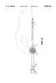
- FIG. 1is a perspective view of a valve holder
- FIG. 2is a top view of a valve holder
- FIG. 3is a perspective view of an alignment member
- FIG. 4is a frontal view of a valve retention lock positioned on a valve holder
- FIG. 5is an side view of a valve holder being grasped
- FIG. 6is an end view of a prosthetic heart valve and the shoes of a valve holder with the shoes positioned on the valve;
- FIG. 7is a top view of a valve holder with the retention lock in the locked position.
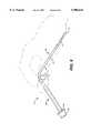
- FIG. 8is a side view of another embodiment of the valve holder.
- Valve holder 2includes a first arm 4 and a second arm 6 coupled at their respective proximal ends 8, 10 by a coupling member 12.
- Coupling member 12serves as a spring between arms 4 and 6.
- coupling member 12is generally "U"-shaped.
- the proximal ends 8, 10 of arms 4, 6are coupled directed with each other and biased to form a spring, similar to the configuration of the common tweezers.
- arms 4, 6comprise two components, an upper spring portion 14 and lower, more rigid portion 16.
- the portions 14, 16may be threaded to screw together, or are otherwise securely coupled together by glue, friction fit or other means at coupling 18.
- coupling member 12biases arms 4, 6 about eight degrees from a centerline A when no load is applied to the arms. (FIGS. 1 and 2 show arms 4, 6 in a fully flexed position.)
- First and second arms 4, 6 and coupling member 12are made from a spring material which may be repeatedly sterilized. Consequently, holder 2 may be used for numerous valve implantations.
- arms 4, 6 and coupling member 12are made from stainless steel.
- Other suitable materialsincluding metal, metal coated with plastic, plastic, or combinations thereof, which may be repeatedly sterilized.
- Suitable plastic compositionsinclude polysulfone, polycarbonate, polyetherimide, and combinations thereof.
- arms 4, 6are elongate members that include medial sections 20, 22, respectively, and distal ends 24, 26, respectively.
- the length of arms 4, 6 from coupling member 12 to the distal endsis about seven inches, and arms 4, 6 are about 0.125 inches thick.
- Positioned at the distal ends 24, 26are valve contact shoes 28, 30.
- Each contact shoeincludes a distal lip 32, a proximal lip 34, and a central body 36.
- the outer surface of central body 36 extending between the lipshas a convex curvature to maximize the surface area of shoes 28, 30 which contact the inner surface of a prosthetic valve ring, as discussed further below.
- Rotation meanscomprise edges 37 of central body 36, and allows the holder to rotate the valve without damaging the leaflets.
- the length of each shoe, from distal to proximal lipis about one-half inch.
- Shoes 28, 30are made from biocompatible materials, including metal, metal coated with plastic, plastic, or combinations thereof, which may be repeatedly sterilized.
- Alignment members 40, 42are positioned near distal ends 24, 26. As shown in FIG. 3, alignment member 40 includes a face 44. Extending from face 44 are two posts 46, 48 which are positioned generally diagonal from each other. The portions 50, 52 of face 44 opposite posts 46, 48 are generally recessed when compared to posts 46, 48 and form receiving areas. Alignment member 42 is configured in the same manner as alignment member 40, except that the posts, and consequently the receiving areas, are rotated ninety degrees. Therefore, when alignment members 40, 42 are properly aligned and moved into contact with each other, the posts of alignment member 40 contact the receiving areas of alignment member 42, and the posts of alignment member 42 contact the receiving areas of alignment member 40.
- alignment members 40, 42are properly coupled, i.e., the posts fit with the receiving areas, shoes 28, 30 are properly aligned to be positioned in a prosthetic heart valve, as shown in FIGS. 1 and 2.
- Alignment members 40, 42are made from biocompatible materials, including metal, metal coated with plastic, plastic, or combinations thereof, which may be repeatedly sterilized.
- leaflet protection stops 64, 66are positioned along the medial sections 20, 22 of arms 4, 6.
- Leaflet protection stops 64, 66extend generally orthogonal to the longitudinal axis of arms 4, 6, and toward each other.
- the length which leaflet stops 64, 66 extend from medial sections 20, 22is selected so that arms 4, 6 cannot over-rotate toward each other to the extent where shoes 28, 30 can impinge upon the leaflets of a valve to be grasped by valve holder 2.
- arms 4 and 6are fully flexed toward each other and leaflet stops 64 and 66 are in contact with each other.
- Shoes 28, 30can still pass into valve ring 86 without contacting leaflets 88.
- Leaflet protection stops 64, 66are made from biocompatible materials, including metal, metal coated with plastic, plastic, or combinations thereof, which may be repeatedly sterilized. In another embodiment, only one stop is used, extending from either the first or second arm.
- a valve retention lock 72is coupled with either first arm 4 or second arm 6, and is rotatable about the arm to selectively lock onto the other arm (as shown by arrow B in FIG. 4).
- valve retention lock 72is coupled with second arm 6.
- Retention lock 72is generally planar and includes a plurality of keys or recesses 74 which represent different valve sizes or ranges of sizes. In the embodiment shown in FIG. 4, there are three recesses 74, one representing valves sizes 19-21 mm, one recess representing valves sizes 23-25, and one recess representing valves sizes 27-33.
- retention lock 72is generally slidable along arms 4 and 6, and coupling member 12.
- valve retention lock 72When retention lock 72 is to be employed, it is slid over limiting member 75 and rotated toward the other arm. Limiting member 75 holds retention lock 72 in place on the arm.
- valve retention lock 72is made from biocompatible materials, including metal, metal coated with plastic, plastic, or combinations thereof, which may be repeatedly sterilized.
- Valve holder 2may also include finger pads 76, positioned on arms 4, 6, generally opposite leaflet protection stops 64, 66, as shown in FIGS. 1 and 2.
- Finger pads 76include an outer surface 78 having ribs or other non-slip surface treatment. Finger pads 76 are made from biocompatible materials, including metal, metal coated with plastic, plastic, or combinations thereof, which may be repeatedly sterilized.
- arms 4, 6may be ribbed or include an outer textured surface to assist in grasping the arms.
- valve holder 2When using valve holder 2, a surgeon grasps it, typically by placing thumb and forefinger on finger pads 76, as shown in FIG. 5. By compressing pads 76, coupling member 12 flexes, moving arms 4, 6 toward each other. As shown in FIG. 2, in order to hold a prosthetic heart valve 80, arms 4, 6 are flexed sufficiently so that shoes 28, 30 extend into regions 82, 84, defined by annular ring 86 and leaflets 88 of valve 80.
- leaflets 88are crucial components of prosthetic valve 80 as they are the components that must repeatedly rotate, thereby allowing blood to flow in one direction but not the opposite direction. It is important that when grasping valve 80, a surgeon place no pressure on leaflets 88.
- leaflet protection stops 64, 66will contact each other before shoes 28, 30 or portions of distal ends 24, 26 can impinge upon leaflets 88. Therefore, when positioning valve holder 2 to grasp valve 80, the surgeon cannot over rotate arms 4, 6 (and possibly damage leaflets 88).
- retention lock 72is used to lock arms 4 and 6 in place for holder 2 to hold a 31 mm valve. Also, retention lock 72 serves to prevent accidentally dropping the valve by inadvertently flexing arms 4, 6. The surgeon may then position the valve and holder, move them around, place a force one the arms, all without fear of separating the valve from the holder. Once the valve is positioned and fixed in the native annulus, a surgeon may rotate the valve if necessary, and/or release retention lock 72 and flex arms 4, 6 to allow shoes 28, 30 to move out of the valve through regions 82, 84. Throughout the manipulations of valve holder 2, the leaflets are not damaged by valve holder 2 due to leaflet protection stops 64, 66.
- arms 4, 6are generally linear.
- arms 4, 6include first and second segments, 90, 92, respectively, forming obtuse angle C.
- angle Cis about 130° degrees.
Landscapes
- Health & Medical Sciences (AREA)
- Cardiology (AREA)
- Oral & Maxillofacial Surgery (AREA)
- Transplantation (AREA)
- Engineering & Computer Science (AREA)
- Biomedical Technology (AREA)
- Heart & Thoracic Surgery (AREA)
- Vascular Medicine (AREA)
- Life Sciences & Earth Sciences (AREA)
- Animal Behavior & Ethology (AREA)
- General Health & Medical Sciences (AREA)
- Public Health (AREA)
- Veterinary Medicine (AREA)
- Prostheses (AREA)
Abstract
Description
Claims (27)
Priority Applications (1)
| Application Number | Priority Date | Filing Date | Title |
|---|---|---|---|
| US08/989,843US5906642A (en) | 1997-12-12 | 1997-12-12 | Universal heart valve holder |
Applications Claiming Priority (1)
| Application Number | Priority Date | Filing Date | Title |
|---|---|---|---|
| US08/989,843US5906642A (en) | 1997-12-12 | 1997-12-12 | Universal heart valve holder |
Publications (1)
| Publication Number | Publication Date |
|---|---|
| US5906642Atrue US5906642A (en) | 1999-05-25 |
Family
ID=25535521
Family Applications (1)
| Application Number | Title | Priority Date | Filing Date |
|---|---|---|---|
| US08/989,843Expired - Fee RelatedUS5906642A (en) | 1997-12-12 | 1997-12-12 | Universal heart valve holder |
Country Status (1)
| Country | Link |
|---|---|
| US (1) | US5906642A (en) |
Cited By (30)
| Publication number | Priority date | Publication date | Assignee | Title |
|---|---|---|---|---|
| US6136017A (en)* | 1999-04-23 | 2000-10-24 | Sulzer Carbomedics Inc. | One handed instrument for spreading a heart valve |
| WO2001008608A1 (en)* | 1999-08-03 | 2001-02-08 | St. Jude Medical, Inc. | Prosthetic ring holder |
| US6582419B1 (en)* | 1999-04-28 | 2003-06-24 | St. Jude Medical, Inc. | Aortic heart valve prosthesis sizer and marker |
| US20040034410A1 (en)* | 2002-08-16 | 2004-02-19 | Holmberg William R. | Annuloplasty ring holder |
| US20060015177A1 (en)* | 2004-07-19 | 2006-01-19 | St. Jude Medical, Inc. | Heart valve support and lid liner system and methods |
| US20060167468A1 (en)* | 2004-11-12 | 2006-07-27 | Shlomo Gabbay | Implantation system and method for loading an implanter with a prosthesis |
| US20070078468A1 (en)* | 2005-09-30 | 2007-04-05 | Ryan Timothy R | Tool and method for implanting an annuloplasty prosthesis |
| US20080021286A1 (en)* | 2004-12-29 | 2008-01-24 | Olof Risto | Retractor |
| US20140257468A1 (en)* | 2013-03-08 | 2014-09-11 | St. Jude Medical, Cardiology Division, Inc. | Valve Holder With Leaflet Protection |
| US20180133454A1 (en)* | 2016-11-15 | 2018-05-17 | Randolf Von Oepen | Delivery catheter distal cap |
| US10639151B2 (en) | 2016-07-29 | 2020-05-05 | Cephea Valve Technologies, Inc. | Threaded coil |
| US10646689B2 (en) | 2016-07-29 | 2020-05-12 | Cephea Valve Technologies, Inc. | Mechanical interlock for catheters |
| US10661052B2 (en) | 2016-07-29 | 2020-05-26 | Cephea Valve Technologies, Inc. | Intravascular device delivery sheath |
| US10874512B2 (en) | 2016-10-05 | 2020-12-29 | Cephea Valve Technologies, Inc. | System and methods for delivering and deploying an artificial heart valve within the mitral annulus |
| US10933216B2 (en) | 2016-08-29 | 2021-03-02 | Cephea Valve Technologies, Inc. | Multilumen catheter |
| US10974027B2 (en) | 2016-07-29 | 2021-04-13 | Cephea Valve Technologies, Inc. | Combination steerable catheter and systems |
| US11045315B2 (en) | 2016-08-29 | 2021-06-29 | Cephea Valve Technologies, Inc. | Methods of steering and delivery of intravascular devices |
| CN113164269A (en)* | 2018-09-20 | 2021-07-23 | 维迪内股份有限公司 | Deliverable transcatheter prosthetic heart valve and delivery method |
| US11109967B2 (en) | 2016-08-29 | 2021-09-07 | Cephea Valve Technologies, Inc. | Systems and methods for loading and deploying an intravascular device |
| US11324495B2 (en) | 2016-07-29 | 2022-05-10 | Cephea Valve Technologies, Inc. | Systems and methods for delivering an intravascular device to the mitral annulus |
| US11724068B2 (en) | 2018-11-16 | 2023-08-15 | Cephea Valve Technologies, Inc. | Intravascular delivery system |
| US12138158B2 (en) | 2019-03-14 | 2024-11-12 | Vdyne, Inc. | Side-deliverable transcatheter prosthetic valves and methods for delivering and anchoring the same |
| US12144731B2 (en) | 2019-01-26 | 2024-11-19 | Vdyne, Inc. | Collapsible inner flow control component for side-deliverable transcatheter heart valve prosthesis |
| US12150852B2 (en) | 2018-12-20 | 2024-11-26 | Vdyne, Inc. | Proximal tab for side-delivered transcatheter heart valves and methods of delivery |
| US12186187B2 (en) | 2018-09-20 | 2025-01-07 | Vdyne, Inc. | Transcatheter deliverable prosthetic heart valves and methods of delivery |
| US12310850B2 (en) | 2018-09-20 | 2025-05-27 | Vdyne, Inc. | Transcatheter deliverable prosthetic heart valves and methods of delivery |
| US12318286B2 (en) | 2019-05-04 | 2025-06-03 | Vdyne, Inc. | Cinch device and method for deployment of a side-delivered prosthetic heart valve in a native annulus |
| US12324737B2 (en) | 2019-03-05 | 2025-06-10 | Vdyne, Inc. | Tricuspid regurgitation control devices for orthogonal transcatheter heart valve prosthesis |
| US12343256B2 (en) | 2019-01-10 | 2025-07-01 | Vdyne, Inc. | Anchor hook for side-delivery transcatheter heart valve prosthesis |
| US12440332B2 (en) | 2021-08-11 | 2025-10-14 | Cephea Valve Technologies, Inc. | Systems and methods for loading and deploying an intravascular device |
Citations (14)
| Publication number | Priority date | Publication date | Assignee | Title |
|---|---|---|---|---|
| SU878285A1 (en)* | 1979-10-02 | 1981-11-07 | 3,а в1итель | Holder of heart artificial valve |
| US4655218A (en)* | 1985-10-23 | 1987-04-07 | Blagoveschensky Gosudarstuvenny Meditsinsky Institut | Prosthetic valve holder |
| WO1992012688A1 (en)* | 1991-01-25 | 1992-08-06 | Zavod 'elektronmash' Pri Konstruktorskom Bjuro Tochnogo Elektronnogo Mashinostroenia | Heart valve prosthesis holder |
| US5522884A (en)* | 1993-02-19 | 1996-06-04 | Medtronic, Inc. | Holder for adjustable mitral & tricuspid annuloplasty rings |
| US5582607A (en)* | 1994-09-09 | 1996-12-10 | Carbomedics, Inc. | Heart valve prosthesis rotator with bendable shaft and drive mechanism |
| US5669919A (en)* | 1996-08-16 | 1997-09-23 | Medtronic, Inc. | Annuloplasty system |
| US5682906A (en)* | 1993-02-22 | 1997-11-04 | Heartport, Inc. | Methods of performing intracardiac procedures on an arrested heart |
| US5716402A (en)* | 1996-08-05 | 1998-02-10 | Tri Technologies, Ltda (A Bvi Corporation) | Heart valve rotator |
| US5716401A (en)* | 1994-04-21 | 1998-02-10 | Medtronic, Inc. | Holder for heart valve |
| US5716398A (en)* | 1988-02-16 | 1998-02-10 | Baxter International, Inc. | Mitral valve rotator assembly |
| US5716370A (en)* | 1996-02-23 | 1998-02-10 | Williamson, Iv; Warren | Means for replacing a heart valve in a minimally invasive manner |
| US5718725A (en)* | 1992-12-03 | 1998-02-17 | Heartport, Inc. | Devices and methods for intracardiac procedures |
| US5735894A (en)* | 1995-05-24 | 1998-04-07 | St. Jude Medical, Inc. | Holder for heart valve prosthesis |
| US5735842A (en)* | 1995-09-11 | 1998-04-07 | St. Jude Medical, Inc. | Low profile manipulators for heart valve prostheses |
- 1997
- 1997-12-12USUS08/989,843patent/US5906642A/ennot_activeExpired - Fee Related
Patent Citations (15)
| Publication number | Priority date | Publication date | Assignee | Title |
|---|---|---|---|---|
| SU878285A1 (en)* | 1979-10-02 | 1981-11-07 | 3,а в1итель | Holder of heart artificial valve |
| US4655218A (en)* | 1985-10-23 | 1987-04-07 | Blagoveschensky Gosudarstuvenny Meditsinsky Institut | Prosthetic valve holder |
| US5716398A (en)* | 1988-02-16 | 1998-02-10 | Baxter International, Inc. | Mitral valve rotator assembly |
| WO1992012688A1 (en)* | 1991-01-25 | 1992-08-06 | Zavod 'elektronmash' Pri Konstruktorskom Bjuro Tochnogo Elektronnogo Mashinostroenia | Heart valve prosthesis holder |
| US5718725A (en)* | 1992-12-03 | 1998-02-17 | Heartport, Inc. | Devices and methods for intracardiac procedures |
| US5522884A (en)* | 1993-02-19 | 1996-06-04 | Medtronic, Inc. | Holder for adjustable mitral & tricuspid annuloplasty rings |
| US5682906A (en)* | 1993-02-22 | 1997-11-04 | Heartport, Inc. | Methods of performing intracardiac procedures on an arrested heart |
| US5713951A (en)* | 1993-02-22 | 1998-02-03 | Heartport, Inc. | Thoracoscopic valve prosthesis delivery device |
| US5716401A (en)* | 1994-04-21 | 1998-02-10 | Medtronic, Inc. | Holder for heart valve |
| US5582607A (en)* | 1994-09-09 | 1996-12-10 | Carbomedics, Inc. | Heart valve prosthesis rotator with bendable shaft and drive mechanism |
| US5735894A (en)* | 1995-05-24 | 1998-04-07 | St. Jude Medical, Inc. | Holder for heart valve prosthesis |
| US5735842A (en)* | 1995-09-11 | 1998-04-07 | St. Jude Medical, Inc. | Low profile manipulators for heart valve prostheses |
| US5716370A (en)* | 1996-02-23 | 1998-02-10 | Williamson, Iv; Warren | Means for replacing a heart valve in a minimally invasive manner |
| US5716402A (en)* | 1996-08-05 | 1998-02-10 | Tri Technologies, Ltda (A Bvi Corporation) | Heart valve rotator |
| US5669919A (en)* | 1996-08-16 | 1997-09-23 | Medtronic, Inc. | Annuloplasty system |
Cited By (48)
| Publication number | Priority date | Publication date | Assignee | Title |
|---|---|---|---|---|
| US6136017A (en)* | 1999-04-23 | 2000-10-24 | Sulzer Carbomedics Inc. | One handed instrument for spreading a heart valve |
| US6582419B1 (en)* | 1999-04-28 | 2003-06-24 | St. Jude Medical, Inc. | Aortic heart valve prosthesis sizer and marker |
| US20030195497A1 (en)* | 1999-04-28 | 2003-10-16 | St. Jude Medical, Inc. | Aortic heart value prosthesis sizer and marker |
| US7338484B2 (en) | 1999-04-28 | 2008-03-04 | St. Jude Medical, Inc. | Aortic heart valve prosthesis sizer and marker |
| US6319280B1 (en) | 1999-08-03 | 2001-11-20 | St. Jude Medical, Inc. | Prosthetic ring holder |
| WO2001008608A1 (en)* | 1999-08-03 | 2001-02-08 | St. Jude Medical, Inc. | Prosthetic ring holder |
| US20040034410A1 (en)* | 2002-08-16 | 2004-02-19 | Holmberg William R. | Annuloplasty ring holder |
| US6966924B2 (en) | 2002-08-16 | 2005-11-22 | St. Jude Medical, Inc. | Annuloplasty ring holder |
| US7389874B2 (en) | 2004-07-19 | 2008-06-24 | St. Jude Medical, Inc. | Heart valve support and storing lid system and methods associated therewith |
| US20060015177A1 (en)* | 2004-07-19 | 2006-01-19 | St. Jude Medical, Inc. | Heart valve support and lid liner system and methods |
| US20060167468A1 (en)* | 2004-11-12 | 2006-07-27 | Shlomo Gabbay | Implantation system and method for loading an implanter with a prosthesis |
| US8287565B2 (en)* | 2004-12-29 | 2012-10-16 | Surg-Mate AB | Retractor |
| US20080021286A1 (en)* | 2004-12-29 | 2008-01-24 | Olof Risto | Retractor |
| US20070078514A1 (en)* | 2005-09-30 | 2007-04-05 | Ryan Timothy R | Method of implanting an annuloplasty prosthesis |
| US8007530B2 (en)* | 2005-09-30 | 2011-08-30 | Medtronic, Inc. | Tool and method for implanting an annuloplasty prosthesis |
| US8048152B2 (en) | 2005-09-30 | 2011-11-01 | Medtronic, Inc. | Method of implanting an annuloplasty prosthesis |
| US20070078468A1 (en)* | 2005-09-30 | 2007-04-05 | Ryan Timothy R | Tool and method for implanting an annuloplasty prosthesis |
| US10028829B2 (en) | 2013-03-08 | 2018-07-24 | St. Jude Medical, Cardiology Division, Inc. | Valve holder with leaflet protection |
| US20140257468A1 (en)* | 2013-03-08 | 2014-09-11 | St. Jude Medical, Cardiology Division, Inc. | Valve Holder With Leaflet Protection |
| US9480563B2 (en)* | 2013-03-08 | 2016-11-01 | St. Jude Medical, Cardiology Division, Inc. | Valve holder with leaflet protection |
| US10661052B2 (en) | 2016-07-29 | 2020-05-26 | Cephea Valve Technologies, Inc. | Intravascular device delivery sheath |
| US10974027B2 (en) | 2016-07-29 | 2021-04-13 | Cephea Valve Technologies, Inc. | Combination steerable catheter and systems |
| US10639151B2 (en) | 2016-07-29 | 2020-05-05 | Cephea Valve Technologies, Inc. | Threaded coil |
| US10646689B2 (en) | 2016-07-29 | 2020-05-12 | Cephea Valve Technologies, Inc. | Mechanical interlock for catheters |
| US12364840B2 (en) | 2016-07-29 | 2025-07-22 | Cephea Valve Technologies, Inc. | Mechanical interlock for catheters |
| US11471645B2 (en) | 2016-07-29 | 2022-10-18 | Cephea Valve Technologies, Inc. | Intravascular device delivery sheath |
| US11324495B2 (en) | 2016-07-29 | 2022-05-10 | Cephea Valve Technologies, Inc. | Systems and methods for delivering an intravascular device to the mitral annulus |
| US11679236B2 (en) | 2016-07-29 | 2023-06-20 | Cephea Valve Technologies, Inc. | Mechanical interlock for catheters |
| US11793973B2 (en) | 2016-07-29 | 2023-10-24 | Cephea Valve Technologies, Inc. | Combination steerable catheter and systems |
| US11045315B2 (en) | 2016-08-29 | 2021-06-29 | Cephea Valve Technologies, Inc. | Methods of steering and delivery of intravascular devices |
| US11109967B2 (en) | 2016-08-29 | 2021-09-07 | Cephea Valve Technologies, Inc. | Systems and methods for loading and deploying an intravascular device |
| US10933216B2 (en) | 2016-08-29 | 2021-03-02 | Cephea Valve Technologies, Inc. | Multilumen catheter |
| US10874512B2 (en) | 2016-10-05 | 2020-12-29 | Cephea Valve Technologies, Inc. | System and methods for delivering and deploying an artificial heart valve within the mitral annulus |
| US11723768B2 (en) | 2016-10-05 | 2023-08-15 | Cephea Valve Technologies, Inc. | Systems and methods for delivering and deploying an artificial heart valve within the mitral annulus |
| US11484408B2 (en) | 2016-11-15 | 2022-11-01 | Cephea Valve Technologies, Inc. | Delivery catheter distal cap |
| US10631981B2 (en)* | 2016-11-15 | 2020-04-28 | Cephea Valve Technologies, Inc. | Delivery catheter distal cap |
| US20180133454A1 (en)* | 2016-11-15 | 2018-05-17 | Randolf Von Oepen | Delivery catheter distal cap |
| CN113164269A (en)* | 2018-09-20 | 2021-07-23 | 维迪内股份有限公司 | Deliverable transcatheter prosthetic heart valve and delivery method |
| US12186187B2 (en) | 2018-09-20 | 2025-01-07 | Vdyne, Inc. | Transcatheter deliverable prosthetic heart valves and methods of delivery |
| US12310850B2 (en) | 2018-09-20 | 2025-05-27 | Vdyne, Inc. | Transcatheter deliverable prosthetic heart valves and methods of delivery |
| US11724068B2 (en) | 2018-11-16 | 2023-08-15 | Cephea Valve Technologies, Inc. | Intravascular delivery system |
| US12150852B2 (en) | 2018-12-20 | 2024-11-26 | Vdyne, Inc. | Proximal tab for side-delivered transcatheter heart valves and methods of delivery |
| US12343256B2 (en) | 2019-01-10 | 2025-07-01 | Vdyne, Inc. | Anchor hook for side-delivery transcatheter heart valve prosthesis |
| US12144731B2 (en) | 2019-01-26 | 2024-11-19 | Vdyne, Inc. | Collapsible inner flow control component for side-deliverable transcatheter heart valve prosthesis |
| US12324737B2 (en) | 2019-03-05 | 2025-06-10 | Vdyne, Inc. | Tricuspid regurgitation control devices for orthogonal transcatheter heart valve prosthesis |
| US12138158B2 (en) | 2019-03-14 | 2024-11-12 | Vdyne, Inc. | Side-deliverable transcatheter prosthetic valves and methods for delivering and anchoring the same |
| US12318286B2 (en) | 2019-05-04 | 2025-06-03 | Vdyne, Inc. | Cinch device and method for deployment of a side-delivered prosthetic heart valve in a native annulus |
| US12440332B2 (en) | 2021-08-11 | 2025-10-14 | Cephea Valve Technologies, Inc. | Systems and methods for loading and deploying an intravascular device |
Similar Documents
| Publication | Publication Date | Title |
|---|---|---|
| US5906642A (en) | Universal heart valve holder | |
| US6319280B1 (en) | Prosthetic ring holder | |
| US6113535A (en) | Surgical retraction apparatus | |
| US6019790A (en) | Heart valve holder having a locking collar | |
| US4585453A (en) | Disposable holder for prosthetic heart valve | |
| US5403305A (en) | Mitral valve prosthesis rotator | |
| US7871432B2 (en) | Heart valve holder for use in valve implantation procedures | |
| US9259316B2 (en) | Aortic valve holder with stent protection and/or ability to decrease valve profile | |
| US5843177A (en) | Apparatus for attaching a handle to an annuloplasty ring implantation device | |
| US7641687B2 (en) | Attachment of a sewing cuff to a heart valve | |
| EP2670356B1 (en) | Adjustable prosthetic anatomical device holder and handle for the implantation of an annuloplasty ring | |
| US6090138A (en) | Universal heart valve holder | |
| US5108401A (en) | Patella cutting clamp | |
| US20080071367A1 (en) | Heart valve holder for use in valve implantation procedures | |
| US6497713B1 (en) | Rotary tissue cutting die | |
| US6214043B1 (en) | Releasable hanger for heart valve prosthesis low profile holder | |
| US8961528B2 (en) | Offset cup impactor with a grasping plate for double mobility implants | |
| US20120022333A1 (en) | Apparatus and system for simultaneous use of multiple instruments | |
| EP0828454A1 (en) | Low profile holder for heart valve prosthesis | |
| US5954709A (en) | Low profile introducer and rotator | |
| US5814101A (en) | Holder for heart valve prosthesis | |
| JP7217705B2 (en) | Medical instrument with saw template | |
| US20040019357A1 (en) | Annuloplasty ring holder | |
| US20050125033A1 (en) | Wound closure apparatus | |
| US20030109921A1 (en) | System for implanting prosthetic heart valves |
Legal Events
| Date | Code | Title | Description |
|---|---|---|---|
| AS | Assignment | Owner name:SULZER CARBOMEDICS INC., TEXAS Free format text:ASSIGNMENT OF ASSIGNORS INTEREST;ASSIGNORS:CAUDILLO, ROBERTO;KLOSTERMEYER, TAMMI E.;CAFFEY, JAMES C.;REEL/FRAME:008922/0233;SIGNING DATES FROM 19971209 TO 19971210 | |
| FEPP | Fee payment procedure | Free format text:PAYOR NUMBER ASSIGNED (ORIGINAL EVENT CODE: ASPN); ENTITY STATUS OF PATENT OWNER: LARGE ENTITY | |
| FPAY | Fee payment | Year of fee payment:4 | |
| AS | Assignment | Owner name:SULZER CARBOMEDICS INC., TEXAS Free format text:RELEASE OF SECURITY INTEREST;ASSIGNORS:UBS AG, STAMFORD BRANCH (ON ITS OWN BEHALF AND AS A SECURITY AGENT);CENTERPULSE USA HOLDING CO., A CORP. OF DELAWARE;CENTERPULSE USA INC., A CORP. OF DELAWARE;AND OTHERS;REEL/FRAME:013496/0824 Effective date:20030121 | |
| FPAY | Fee payment | Year of fee payment:8 | |
| FEPP | Fee payment procedure | Free format text:PAYOR NUMBER ASSIGNED (ORIGINAL EVENT CODE: ASPN); ENTITY STATUS OF PATENT OWNER: LARGE ENTITY Free format text:PAYER NUMBER DE-ASSIGNED (ORIGINAL EVENT CODE: RMPN); ENTITY STATUS OF PATENT OWNER: LARGE ENTITY | |
| REMI | Maintenance fee reminder mailed | ||
| LAPS | Lapse for failure to pay maintenance fees | ||
| STCH | Information on status: patent discontinuation | Free format text:PATENT EXPIRED DUE TO NONPAYMENT OF MAINTENANCE FEES UNDER 37 CFR 1.362 | |
| FP | Lapsed due to failure to pay maintenance fee | Effective date:20110525 | |
| AS | Assignment | Owner name:CORCYM S.R.L., ITALY Free format text:ASSIGNMENT OF ASSIGNORS INTEREST;ASSIGNOR:LIVANVOA USA, INC.;REEL/FRAME:056544/0121 Effective date:20210601 |