US5906597A - Patient-controlled drug administration device - Google Patents
Patient-controlled drug administration deviceDownload PDFInfo
- Publication number
- US5906597A US5906597AUS09/094,111US9411198AUS5906597AUS 5906597 AUS5906597 AUS 5906597AUS 9411198 AUS9411198 AUS 9411198AUS 5906597 AUS5906597 AUS 5906597A
- Authority
- US
- United States
- Prior art keywords
- chamber
- agent
- outlet lumen
- diaphragm
- flow
- Prior art date
- Legal status (The legal status is an assumption and is not a legal conclusion. Google has not performed a legal analysis and makes no representation as to the accuracy of the status listed.)
- Expired - Lifetime
Links
- 238000001647drug administrationMethods0.000titledescription3
- 239000000599controlled substanceSubstances0.000titledescription2
- 239000012530fluidSubstances0.000claimsabstractdescription45
- 238000011144upstream manufacturingMethods0.000claimsabstractdescription31
- 238000004891communicationMethods0.000claimsabstractdescription25
- 230000007246mechanismEffects0.000claimsabstractdescription18
- 239000003795chemical substances by applicationSubstances0.000claimsdescription43
- 238000005336crackingMethods0.000claimsdescription23
- 239000012528membraneSubstances0.000claimsdescription15
- 239000003814drugSubstances0.000claimsdescription10
- 239000007788liquidSubstances0.000claimsdescription10
- 229940124597therapeutic agentDrugs0.000claimsdescription7
- 238000007789sealingMethods0.000claimsdescription4
- 239000013589supplementSubstances0.000abstractdescription2
- 230000001105regulatory effectEffects0.000description5
- 229940079593drugDrugs0.000description3
- 238000005429filling processMethods0.000description3
- 238000001802infusionMethods0.000description3
- 210000000707wristAnatomy0.000description3
- 208000002193PainDiseases0.000description2
- 230000000202analgesic effectEffects0.000description2
- 239000011324beadSubstances0.000description2
- 230000006835compressionEffects0.000description2
- 238000007906compressionMethods0.000description2
- 238000012986modificationMethods0.000description2
- 230000004048modificationEffects0.000description2
- 230000002093peripheral effectEffects0.000description2
- 239000004033plasticSubstances0.000description2
- 229920003023plasticPolymers0.000description2
- 230000000153supplemental effectEffects0.000description2
- 208000000094Chronic PainDiseases0.000description1
- 241000287181Sturnus vulgarisSpecies0.000description1
- 239000000853adhesiveSubstances0.000description1
- 230000001070adhesive effectEffects0.000description1
- 229940035676analgesicsDrugs0.000description1
- 239000000730antalgic agentSubstances0.000description1
- 238000013459approachMethods0.000description1
- 230000001684chronic effectEffects0.000description1
- 238000010276constructionMethods0.000description1
- 230000000994depressogenic effectEffects0.000description1
- 230000003467diminishing effectEffects0.000description1
- 230000000694effectsEffects0.000description1
- 210000003811fingerAnatomy0.000description1
- 238000002513implantationMethods0.000description1
- 238000002347injectionMethods0.000description1
- 239000007924injectionSubstances0.000description1
- 238000007918intramuscular administrationMethods0.000description1
- 238000007913intrathecal administrationMethods0.000description1
- 238000001990intravenous administrationMethods0.000description1
- 230000007774longtermEffects0.000description1
- 238000012423maintenanceMethods0.000description1
- 238000007726management methodMethods0.000description1
- 238000004519manufacturing processMethods0.000description1
- 239000000463materialSubstances0.000description1
- 238000007920subcutaneous administrationMethods0.000description1
- 238000001356surgical procedureMethods0.000description1
- 210000003813thumbAnatomy0.000description1
- 238000003466weldingMethods0.000description1
Images

Classifications
- A—HUMAN NECESSITIES
- A61—MEDICAL OR VETERINARY SCIENCE; HYGIENE
- A61M—DEVICES FOR INTRODUCING MEDIA INTO, OR ONTO, THE BODY; DEVICES FOR TRANSDUCING BODY MEDIA OR FOR TAKING MEDIA FROM THE BODY; DEVICES FOR PRODUCING OR ENDING SLEEP OR STUPOR
- A61M5/00—Devices for bringing media into the body in a subcutaneous, intra-vascular or intramuscular way; Accessories therefor, e.g. filling or cleaning devices, arm-rests
- A61M5/14—Infusion devices, e.g. infusing by gravity; Blood infusion; Accessories therefor
- A61M5/142—Pressure infusion, e.g. using pumps
- A61M5/14212—Pumping with an aspiration and an expulsion action
- A61M5/1424—Manually operated pumps
- A—HUMAN NECESSITIES
- A61—MEDICAL OR VETERINARY SCIENCE; HYGIENE
- A61M—DEVICES FOR INTRODUCING MEDIA INTO, OR ONTO, THE BODY; DEVICES FOR TRANSDUCING BODY MEDIA OR FOR TAKING MEDIA FROM THE BODY; DEVICES FOR PRODUCING OR ENDING SLEEP OR STUPOR
- A61M5/00—Devices for bringing media into the body in a subcutaneous, intra-vascular or intramuscular way; Accessories therefor, e.g. filling or cleaning devices, arm-rests
- A61M5/14—Infusion devices, e.g. infusing by gravity; Blood infusion; Accessories therefor
- A61M2005/1401—Functional features
- A61M2005/1405—Patient controlled analgesia [PCA]
Definitions
- the present inventionrelates to the field of patient-controlled drug administration devices. More specifically, it relates to an apparatus for administering a medicinal agent to a patient that allows the patient to provide a precisely controlled self-administered bolus dose of the agent in addition to a continuous flow of the agent.
- PCA devicesIn chronic care situations, or in home care situations, it is impractical, in many cases, to have a medical practitioner available whenever a patient wants or needs a supplemental bolus dose. Consequently, a number of drug administration devices have been developed that allow the patient to self-administer a controlled bolus dose. These devices (sometimes called patient-controlled administration devices, or "PCA” devices) typically provide a bolus dose that is no more than a predetermined volume, and they also typically include a "lock-out” mechanism, by which is meant a mechanism that limits the frequency of bolus dose administration, or that limits the total bolus dose volume administered over a selected time interval. Some, but not all, prior art PCA devices also allow a controlled continuous flow of the agent between bolus doses.
- PCApatient-controlled administration devices
- non-implantable PCA devicethat provides convenient, measured, patient-controlled bolus doses of a therapeutic agent, and that also allows for a regulated continuous or basal flow of the agent. Furthermore, it would be advantageous if such a device were to have a "lock-out" mechanism that limits the total bolus dose volume delivered at any one time or over any specified time interval. In addition, it would be advantageous for such a device to be simply constructed and easily and inexpensively manufactured, so that it may be made as a single-patient disposable apparatus.
- the present inventionis a PCA device comprising a fluid conduit having an upstream portion and a downstream portion, a first flow-restricting orifice in the upstream portion, a second flow-restricting orifice in the downstream portion, a pressure-responsive check valve in the downstream portion in parallel with the second flow-restricting orifice, and a bolus dose delivery mechanism including a chamber in fluid communication between the upstream portion and the downstream portion. Continuous flow is provided through the first flow-restricting orifice, the chamber, and the second flow-restrictive orifice, the continuous flow serving to fill the chamber at a controlled rate through the first flow-restrictive orifice.
- the bolus dose delivery mechanismis manually actuable to express the contents of the chamber through the check valve to supplement the continuous flow through the downstream portion.
- the bolus dose delivery mechanismcomprises a resilient diaphragm that forms a sealed closure for the chamber.
- the diaphragmis movable from a decompressed position to a compressed position by a plunger that is in direct engagement with the exterior surface of the diaphragm, and it is restored to the decompressed position by the flow of fluid into the chamber.
- a liquid therapeutic agentis continuously delivered, under pressure, to the chamber through the upstream portion at a flow rate controlled by the first flow-restricting orifice.
- the agentfills the chamber against the resistance offered by the diaphragm, the fluid flow pushing the diaphragm from its compressed to its decompressed position as the chamber fills.
- a fractional portion of the agent that flows into the chamberalso flows out of the chamber, throughout the filling process, through the second flow-restricting orifice. All of the outflow is through the second flow-restricting orifice, the pressure of the flow being less than the cracking pressure of the check valve.
- the diaphragmWhen the chamber is filled to capacity, after a predetermined time interval, the diaphragm is in its fully decompressed position, in which it offers little or no resistance to the fluid flow into the chamber. With the chamber filled, the continuous flow rate through the device achieves a predetermined steady state, regulated by the first and second flow-restricting orifices.
- the plungerWhen a bolus dose is desired, the plunger is depressed to push the diaphragm toward its compressed position. This compression of the volume of the chamber pressurizes its contents to a pressure above the cracking pressure of the check valve, thereby opening the check valve so that the contents of the chamber are expressed through the check valve. Because the open check valve offers less flow resistance than the second flow-restricting orifice that is in parallel with it, substantially all of the outflow from the chamber is through the check valve, rather than the second flow-restricting orifice.
- the chamberis refilled, as described above, by the continuous flow of the agent. Because a predetermined time interval must elapse before the chamber is completely refilled and ready to deliver another bolus dose on demand, the maximum volume of the total bolus dose deliverable over any given period of time is defined by a predetermined limit. Thus, the above-described lock-out function is thereby provided.
- the subject inventionprovides both a controlled continuous (basal) flow and a controlled bolus dose on demand.
- the total volume of the bolus dose deliverable over a given period of timeis, however, limited to a predetermined maximum by the above-described lock-out function.
- These capabilitiesare achieved in device that may be made small enough and light enough in weight to be comfortably worn (e.g., on the wrist) by a patient.
- a PCA device in accordance with the present inventionis simple in construction, and may therefore be manufactured inexpensively, so as to be adapted for single patient, disposable use. Such simplicity also lends itself to reliability and ease of maintenance and care.
- FIG. 1is a semi-schematic view of a drug infusion system employing a patient-controlled administration (PCA) device in accordance with a preferred embodiment of the present invention
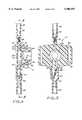
- FIG. 2is a longitudinal cross-sectional view of a PCA device in accordance with a preferred embodiment of the present invention, taken along line 2--2 of FIG. 1, showing the diaphragm of the bolus dose delivery mechanism in its compressed position;
- FIG. 3is an enlarged detailed view of the check valve of the PCA device of FIG. 2, as encompassed within the broken outline 3 of FIG. 2;
- FIG. 4is a cross-sectional view, similar to FIG. 2, but showing the diaphragm of the bolus dose delivery mechanism in its decompressed position;
- FIG. 5is a cross-sectional view taken along line 5--5 of FIG. 4.
- FIG. 1shows a drug infusion system 10 employing a patient-controlled administration (PCA) device 12 in accordance with a preferred embodiment of the present invention.
- the systemcomprises a pressurized fluid source 14 that holds a supply of a liquid therapeutic agent, and that pumps the agent into the PCA device 12 through a supply conduit 18 under a predetermined pressure.
- the supply conduit 18is fluidly connected to the upstream side of the PCA device 12, as will be described below.
- the downstream side of the PCA device 12is fluidly connected to a delivery tube 20, as described below, which terminates in a needle (not shown), which may be configured for intravenous, subcutaneous, intramuscular, or intrathecal injection.
- FIGS. 2 through 5illustrate the PCA device 12 in detail.
- the device 12comprises a housing 22 defining a fluid conduit having an upstream portion 24 and a downstream portion 26.
- the upstream portion 24is fluidly connectable to the supply conduit 18, while the downstream portion 26 is fluidly connectable to the delivery conduit 20.
- the fluid conduit of the PCA device 12includes a chamber 28 having an inlet port 30 in fluid communication with the upstream portion 24 and first and second outlet ports 32, 34 in fluid communication with the downstream portion 26.
- the chamber 28has a maximum volume of about 0.5 ml when filled.
- a first or upstream flow-restricting orifice 36is contained within the upstream portion 24, and a second or downstream flow-restricting orifice 38 is contained within the first outlet port 32 at the juncture with the downstream portion 26.
- the PCA device 12includes a bolus dose delivery mechanism, which is best described with reference to FIG. 4.
- the bolus dose delivery mechanismincludes the chamber 28, which is enclosed by the housing 22 on all sides except for one side that is sealed by a resilient diaphragm 40.
- the diaphragm 40has a raised central portion 42 that is directly engaged by the inner end of a plunger 44 that is axially movable within a cylindrical fitting 46.
- the diaphragm 40also has a peripheral bead 48 that seats in a conforming circular groove 50 in the housing 22.
- a peripheral skirt 51is provided circumferentially around the distal (inner) end of the cylindrical fitting 46.
- the skirt 51defines an annular slot 52 between itself and the distal end of the fitting 46.
- the slot 52receives an annular lip 53 that extends proximally (outwardly) from the housing 22, whereby the fitting 46 is attached to the housing 22 and secured thereto by means such as a suitable adhesive, or by ultrasonic welding.
- the fitting 46is thus attached to the housing 22, the distal (inner) end of the fitting presses the diaphragm bead 48 firmly into the groove 50, creating a fluid-tight seal therebetween.
- the plunger 44has a circumferential ridge 54 that is engageable against the distal or interior-facing side of an annular shoulder 56 within the cylindrical fitting 46.
- the engagement between the shoulder 56 and the ridge 54limits the travel of the plunger 44 in the proximal or outward direction within the cylindrical fitting 46 under the resilient force of the diaphragm 40.
- the plunger 44is thus captured between the diaphragm 40 and the shoulder 56.
- the cylindrical fitting 46has an open proximal or outer end through which the proximal end of the plunger 44 is accessible to the finger or thumb of the patient or other user of the device 12.
- the proximal end of the plunger 44forms a pushbutton 58 (FIG. 1) for manual actuation of the bolus dose delivery mechanism.
- the check valve 60comprises a tubular fitting 62 tapered toward its downstream end, which is terminated by a knob-like valve body 64.
- An outlet orifice 66is provided in the tapered portion of the tubular fitting 62 just upstream from the valve body 64.
- a conformal flexible membrane 68is fixed around the exterior of the tubular fitting 62, covering the outlet orifice 66 and extending over most of the valve body 64.
- the membrane 68functions much as a "duck-bill" valve element, sealing the orifice 66 (as shown in FIGS. 2, 4, and 5) until the fluid pressure in the second outlet port 34 reaches a predetermined "cracking pressure” that separates the membrane 68 from the valve body 64 and thus opens the orifice 66, as shown in FIG. 3.
- the housing 22advantageously is formed with a pair of laterally-extending flaps 70, each of which is provided with a longitudinal slot 72.
- the slots 72are configured to accommodate a wrist strap (not shown), allowing the device 12 to be worn on a patient's wrist (not shown).
- a liquid therapeutic agentis continuously delivered from the pressurized fluid source 14 to the chamber 28, through the supply conduit 18, to the upstream portion 24 of the PCA device 12.
- the liquidflows into the chamber 28 through the inlet 30 at a flow rate that is regulated by the first flow-restricting orifice 36.
- the flow rate through the inlet 30is regulated to about 2.5 ml/hr.
- the liquidfills the chamber 28, non-linearly versus time, against the diminishing resistance offered by the diaphragm 40, the fluid flow pushing the diaphragm 40 from its compressed position (FIG. 2) to its decompressed position (FIG. 4) as the chamber 28 fills.
- the diaphragm 40As the diaphragm 40 is moved from its compressed position to its decompressed position, it pushes the plunger 44 outwardly (in a proximal direction) within the cylindrical fitting 46.
- the diaphragm 40reaches its fully decompressed position when the chamber 28 is filled to capacity; at this point, the plunger 44 is pushed to its proximal limit of travel at which its ridge 54 abuts against the shoulder 56.
- a fractional portion of the liquid that flows into the chamber 28also flows out of the chamber 28 through the first outlet port 32, the second flow-restricting orifice 38, and the outlet portion 26. All of the outflow is through the first outlet port 32 and the second flow-restricting orifice 38, because the pressure of the flow is less than the cracking pressure of the check valve 60.
- This outflowis regulated by the second flow-restricting orifice 38 to about 0.5 ml/hr during the chamber filling process.
- the 0.5 ml chamberis filled to capacity in about 15 minutes.
- the diaphragm 40when the chamber 28 is filled to capacity, the diaphragm 40 is at its fully decompressed position. In this position, it offers little or no resistance to the fluid flow through the chamber 28. Consequently, once the chamber 28 is filled, the continuous flow rate through the device increases to a steady state value of about 1.0 ml/hr, limited by the second flow-restricting orifice 38.
- the plunger 44When a bolus dose is desired, the plunger 44 is pushed distally into the cylindrical fitting 46 to push the diaphragm 40 toward its compressed position. This results in a compression of the volume of the chamber 28 that pressurizes its contents to a pressure above the cracking pressure of the check valve 60, thereby opening the check valve 60 so that the contents of the chamber 28 are expressed through the check valve orifice 66. Because the open check valve 60 offers less flow resistance that the second flow-restricting orifice 38 that is in parallel with it, substantially all of the outflow from the chamber 28 is through the second outlet port 34 and the check valve 60, rather than the second flow-restricting orifice 38. The outflow from the check valve 60 enters the downstream portion 26 of the fluid conduit defined by the hosing 22, and then enters the delivery tube 20 as a bolus dose of the agent.
- the chamber 28is refilled, as described above, by the continuous flow of the liquid agent. As described above, the filling of the chamber 28 returns the plunger 44 to its starling (proximal) position. Thus, no separate spring is required for the plunger's return movement, because the plunger return function is provided by the net effect of the pressurized fluid flow and the resistance of the diaphragm 40. The continuous flow through the first outlet port 32 is re-established almost immediately after the bolus dose is delivered.
- the maximum volume of the total bolus dose deliverable over any given period of timeis defined by a predetermined limit.
- the maximum hourly bolus dose volumeis 2.0 ml.
- the PCA device 12 of the present inventionprovides both a continuous flow and a bolus dose through nearly identical flow paths, the only difference being that the continuous flow enters the downstream portion 26 through the first outlet port 32, while the bolus dose enters the downstream portion 26 through the second outlet port 34.
- parallel delivery systems for the continuous flow and the bolus doseare not required.
- the present inventionoffers significant operational advantages that reduce the likelihood of accidental overdosing. Specifically, if the check valve 60 and/or the downstream flow restricting orifice 38 fails, total fluid flow through the device 12 is limited by the upstream flow restricting orifice 36. If the upstream flow restricting orifice 36 fails, continuous fluid flow to the delivery tube 20 (and thus to the patient) is limited by the downstream flow restricting orifice 38.
- All of the components of the PCA device 12, except the diaphragm 40 and the check valve membrane 68,may be made of suitable injection-molded polymeric plastics, as is conventional in the art.
- the diaphragm 40 and the check valve membrane 68may be made from any suitable elastomeric polymeric plastic material, as is well-known in the art.
- the device 12may be made inexpensively and therefore acceptable for single-patient, disposable use.
Landscapes
- Health & Medical Sciences (AREA)
- Vascular Medicine (AREA)
- Engineering & Computer Science (AREA)
- Anesthesiology (AREA)
- Biomedical Technology (AREA)
- Heart & Thoracic Surgery (AREA)
- Hematology (AREA)
- Life Sciences & Earth Sciences (AREA)
- Animal Behavior & Ethology (AREA)
- General Health & Medical Sciences (AREA)
- Public Health (AREA)
- Veterinary Medicine (AREA)
- Infusion, Injection, And Reservoir Apparatuses (AREA)
- Medicines That Contain Protein Lipid Enzymes And Other Medicines (AREA)
- Ultra Sonic Daignosis Equipment (AREA)
Abstract
Description
Claims (20)
Priority Applications (12)
| Application Number | Priority Date | Filing Date | Title |
|---|---|---|---|
| US09/094,111US5906597A (en) | 1998-06-09 | 1998-06-09 | Patient-controlled drug administration device |
| KR1020007013942AKR100589927B1 (en) | 1998-06-09 | 1999-06-08 | Liquid therapeutic device |
| PT99955437TPT1083949E (en) | 1998-06-09 | 1999-06-08 | PATIENT CONTROLLED DRUG ADMINISTRATION DEVICE |
| DK99955437TDK1083949T3 (en) | 1998-06-09 | 1999-06-08 | Patient controlled drug administration device |
| EP99955437AEP1083949B1 (en) | 1998-06-09 | 1999-06-08 | Patient-controlled drug administration device |
| JP2000553157AJP4156801B2 (en) | 1998-06-09 | 1999-06-08 | Patient controlled drug delivery device |
| AT99955437TATE281852T1 (en) | 1998-06-09 | 1999-06-08 | PATIENT-CONTROLLED DRUG ADMINISTRATION DEVICE |
| CA002334588ACA2334588A1 (en) | 1998-06-09 | 1999-06-08 | Patient-controlled drug administration device |
| AU43366/99AAU761868B2 (en) | 1998-06-09 | 1999-06-08 | Patient-controlled drug administration device |
| DE69921809TDE69921809T2 (en) | 1998-06-09 | 1999-06-08 | Patient controlled drug delivery devices |
| ES99955437TES2233084T3 (en) | 1998-06-09 | 1999-06-08 | DEVICE FOR THE ADMINISTRATION OF DRUGS CONTROLLED BY THE PATIENT. |
| PCT/US1999/012852WO1999064090A1 (en) | 1998-06-09 | 1999-06-08 | Patient-controlled drug administration device |
Applications Claiming Priority (1)
| Application Number | Priority Date | Filing Date | Title |
|---|---|---|---|
| US09/094,111US5906597A (en) | 1998-06-09 | 1998-06-09 | Patient-controlled drug administration device |
Publications (1)
| Publication Number | Publication Date |
|---|---|
| US5906597Atrue US5906597A (en) | 1999-05-25 |
Family
ID=22243065
Family Applications (1)
| Application Number | Title | Priority Date | Filing Date |
|---|---|---|---|
| US09/094,111Expired - LifetimeUS5906597A (en) | 1998-06-09 | 1998-06-09 | Patient-controlled drug administration device |
Country Status (12)
| Country | Link |
|---|---|
| US (1) | US5906597A (en) |
| EP (1) | EP1083949B1 (en) |
| JP (1) | JP4156801B2 (en) |
| KR (1) | KR100589927B1 (en) |
| AT (1) | ATE281852T1 (en) |
| AU (1) | AU761868B2 (en) |
| CA (1) | CA2334588A1 (en) |
| DE (1) | DE69921809T2 (en) |
| DK (1) | DK1083949T3 (en) |
| ES (1) | ES2233084T3 (en) |
| PT (1) | PT1083949E (en) |
| WO (1) | WO1999064090A1 (en) |
Cited By (94)
| Publication number | Priority date | Publication date | Assignee | Title |
|---|---|---|---|---|
| WO2001097876A1 (en) | 2000-06-21 | 2001-12-27 | Mckinley Medical, Lllp | Multi-dose infusion pump providing minimal flow between doses |
| US6485461B1 (en) | 2000-04-04 | 2002-11-26 | Insulet, Inc. | Disposable infusion device |
| WO2003026727A1 (en)* | 2001-09-28 | 2003-04-03 | Lifevent Limited | sETHOD AND APPARATUS FOR DELIVERY OF MEDICATION |
| US6652482B2 (en) | 2000-08-17 | 2003-11-25 | Milestone Scientific Inc | Dental anesthetic and delivery injection unit with automated rate control |
| US6656158B2 (en) | 2002-04-23 | 2003-12-02 | Insulet Corporation | Dispenser for patient infusion device |
| US6656159B2 (en) | 2002-04-23 | 2003-12-02 | Insulet Corporation | Dispenser for patient infusion device |
| US6669669B2 (en) | 2001-10-12 | 2003-12-30 | Insulet Corporation | Laminated patient infusion device |
| US20040015131A1 (en)* | 2002-07-16 | 2004-01-22 | Flaherty J. Christopher | Flow restriction system and method for patient infusion device |
| US20040027083A1 (en)* | 2002-04-26 | 2004-02-12 | Toyoda Koki Kabushiki Kaisha | Motor control device |
| US6692457B2 (en) | 2002-03-01 | 2004-02-17 | Insulet Corporation | Flow condition sensor assembly for patient infusion device |
| US6699218B2 (en) | 2000-11-09 | 2004-03-02 | Insulet Corporation | Transcutaneous delivery means |
| US20040064096A1 (en)* | 2002-09-30 | 2004-04-01 | Flaherty J. Christopher | Components and methods for patient infusion device |
| US20040064088A1 (en)* | 2002-09-30 | 2004-04-01 | William Gorman | Dispenser components and methods for patient infusion device |
| US6723072B2 (en) | 2002-06-06 | 2004-04-20 | Insulet Corporation | Plunger assembly for patient infusion device |
| US20040078028A1 (en)* | 2001-11-09 | 2004-04-22 | Flaherty J. Christopher | Plunger assembly for patient infusion device |
| US20040087894A1 (en)* | 2000-09-08 | 2004-05-06 | Flaherty J. Christopher | Devices, systems and methods for patient infusion |
| US6749587B2 (en) | 2001-02-22 | 2004-06-15 | Insulet Corporation | Modular infusion device and method |
| US20040116866A1 (en)* | 2002-12-17 | 2004-06-17 | William Gorman | Skin attachment apparatus and method for patient infusion device |
| US20040127860A1 (en)* | 2002-12-31 | 2004-07-01 | I Flow Corp | Patient controlled drug administration device |
| US6768425B2 (en) | 2000-12-21 | 2004-07-27 | Insulet Corporation | Medical apparatus remote control and method |
| US20040153032A1 (en)* | 2002-04-23 | 2004-08-05 | Garribotto John T. | Dispenser for patient infusion device |
| US6830558B2 (en) | 2002-03-01 | 2004-12-14 | Insulet Corporation | Flow condition sensor assembly for patient infusion device |
| US20050065760A1 (en)* | 2003-09-23 | 2005-03-24 | Robert Murtfeldt | Method for advising patients concerning doses of insulin |
| US20050070847A1 (en)* | 2003-09-29 | 2005-03-31 | Van Erp Wilhelmus Petrus Martinus Maria | Rapid-exchange balloon catheter with hypotube shaft |
| US6896151B1 (en) | 2002-11-04 | 2005-05-24 | Owens-Illinois Closure Inc. | Self-closing fluid dispensing closure |
| US20050182366A1 (en)* | 2003-04-18 | 2005-08-18 | Insulet Corporation | Method For Visual Output Verification |
| US20050238507A1 (en)* | 2002-04-23 | 2005-10-27 | Insulet Corporation | Fluid delivery device |
| US6960192B1 (en) | 2002-04-23 | 2005-11-01 | Insulet Corporation | Transcutaneous fluid delivery system |
| US6981967B2 (en) | 2001-06-01 | 2006-01-03 | I-Flow Corporation | Large volume bolus device and method |
| US20060045780A1 (en)* | 2004-09-01 | 2006-03-02 | Pekar Robert W | Outlet check valve for fluid bladders |
| US20060122562A1 (en)* | 2004-11-19 | 2006-06-08 | Mckinley Medical L.L.L.P. | Controlled-volume infusion device |
| US20060141773A1 (en)* | 2004-12-29 | 2006-06-29 | Kim Yung P | Method of forming metal line in semiconductor device |
| US20060178633A1 (en)* | 2005-02-03 | 2006-08-10 | Insulet Corporation | Chassis for fluid delivery device |
| US20060271022A1 (en)* | 2005-05-25 | 2006-11-30 | Palion Medical Corporation | Multi-reservoir implantable pump with variable flow rate capabilities |
| US20080009787A1 (en)* | 2006-05-17 | 2008-01-10 | Jacobsen Stephen C | Method and apparatus for presetting device operating levels with display |
| US20080257410A1 (en)* | 2007-04-20 | 2008-10-23 | Cardinal Health 303, Inc. | Fluid flow control system having capillary fluid flow restrictor |
| US20080319393A1 (en)* | 2005-09-27 | 2008-12-25 | Antlae Llc | Self-Powered Portable Syringe Pump |
| US20090227960A1 (en)* | 2005-12-12 | 2009-09-10 | Zoran Milijasevic | Flow Control Assembly Including a Valve and Flow Controller |
| US20100100038A1 (en)* | 2008-10-15 | 2010-04-22 | Symbios Medical Products, Llc | Electronic flow control |
| US7708730B2 (en) | 2006-01-30 | 2010-05-04 | Palyon Medical (Bvi) Limited | Template system for multi-reservoir implantable pump |
| US20100140290A1 (en)* | 2002-08-13 | 2010-06-10 | Daniel Py | Container and Valve Assembly for Storing and Dispensing Substances, and Related Method |
| US20100217209A1 (en)* | 2009-02-20 | 2010-08-26 | University Of Southern California | Drug delivery device with in-plane bandpass regulation check valve in heat-shrink packaging |
| US20100222769A1 (en)* | 2009-02-20 | 2010-09-02 | University Of Southern California | Mems electrochemical bellows actuator |
| EP2383006A1 (en)* | 2010-04-27 | 2011-11-02 | Astra Tech AB | Flow control device for medical liquid |
| US20120150139A1 (en)* | 2008-12-12 | 2012-06-14 | Roche Diagnostics International Ag | System For Ambulatory Drug Infusion Comprising A Filling Apparatus For Flexible Containers, Container Assembly, And Use Of A Flexible Container |
| US8226597B2 (en) | 2002-06-21 | 2012-07-24 | Baxter International, Inc. | Fluid delivery system and flow control therefor |
| US8419638B2 (en) | 2007-11-19 | 2013-04-16 | Proteus Digital Health, Inc. | Body-associated fluid transport structure evaluation devices |
| US8591456B2 (en) | 2011-12-28 | 2013-11-26 | Palyon Medical (Bvi) Limited | Multiple reservoir programmable pump |
| US8814829B2 (en) | 2010-08-12 | 2014-08-26 | Baxter International Inc. | Drug delivery device for fluid restricted patients |
| US9008761B2 (en) | 2010-02-01 | 2015-04-14 | Proteus Digital Health, Inc. | Two-wrist data gathering system |
| US9014779B2 (en) | 2010-02-01 | 2015-04-21 | Proteus Digital Health, Inc. | Data gathering system |
| US9084566B2 (en) | 2006-07-07 | 2015-07-21 | Proteus Digital Health, Inc. | Smart parenteral administration system |
| US9125979B2 (en) | 2007-10-25 | 2015-09-08 | Proteus Digital Health, Inc. | Fluid transfer port information system |
| US9132233B2 (en) | 2010-08-26 | 2015-09-15 | B. Braun Melsungen Ag | Infusion control device |
| US9222819B2 (en) | 2009-02-20 | 2015-12-29 | University Of Southern California | Tracking and controlling fluid delivery from chamber |
| US10342926B2 (en) | 2016-05-26 | 2019-07-09 | Insulet Corporation | Single dose drug delivery device |
| US10363372B2 (en) | 2016-08-12 | 2019-07-30 | Insulet Corporation | Plunger for drug delivery device |
| US10441723B2 (en) | 2016-08-14 | 2019-10-15 | Insulet Corporation | Variable fill drug delivery device |
| US10603440B2 (en) | 2017-01-19 | 2020-03-31 | Insulet Corporation | Cartridge hold-up volume reduction |
| US10695485B2 (en) | 2017-03-07 | 2020-06-30 | Insulet Corporation | Very high volume user filled drug delivery device |
| US10751478B2 (en) | 2016-10-07 | 2020-08-25 | Insulet Corporation | Multi-stage delivery system |
| US10780217B2 (en) | 2016-11-10 | 2020-09-22 | Insulet Corporation | Ratchet drive for on body delivery system |
| US10874803B2 (en) | 2018-05-31 | 2020-12-29 | Insulet Corporation | Drug cartridge with drive system |
| US10898656B2 (en) | 2017-09-26 | 2021-01-26 | Insulet Corporation | Needle mechanism module for drug delivery device |
| US10973978B2 (en) | 2017-08-03 | 2021-04-13 | Insulet Corporation | Fluid flow regulation arrangements for drug delivery devices |
| US11045603B2 (en) | 2017-02-22 | 2021-06-29 | Insulet Corporation | Needle insertion mechanisms for drug containers |
| US11090434B2 (en) | 2015-11-24 | 2021-08-17 | Insulet Corporation | Automated drug delivery system |
| US11147931B2 (en) | 2017-11-17 | 2021-10-19 | Insulet Corporation | Drug delivery device with air and backflow elimination |
| US11229741B2 (en) | 2012-03-30 | 2022-01-25 | Insulet Corporation | Fluid delivery device, transcutaneous access tool and fluid drive mechanism for use therewith |
| US11229736B2 (en) | 2018-06-06 | 2022-01-25 | Insulet Corporation | Linear shuttle pump for drug delivery |
| US11280327B2 (en) | 2017-08-03 | 2022-03-22 | Insulet Corporation | Micro piston pump |
| US11364341B2 (en) | 2015-11-25 | 2022-06-21 | Insulet Corporation | Wearable medication delivery device |
| US11369735B2 (en) | 2019-11-05 | 2022-06-28 | Insulet Corporation | Component positioning of a linear shuttle pump |
| US11446435B2 (en) | 2018-11-28 | 2022-09-20 | Insulet Corporation | Drug delivery shuttle pump system and valve assembly |
| US20230277375A1 (en)* | 2020-07-17 | 2023-09-07 | Shl Medical Ag | Micro dosing device and method of assembly of the micro dosing device |
| US11786668B2 (en) | 2017-09-25 | 2023-10-17 | Insulet Corporation | Drug delivery devices, systems, and methods with force transfer elements |
| US11857763B2 (en) | 2016-01-14 | 2024-01-02 | Insulet Corporation | Adjusting insulin delivery rates |
| US11865299B2 (en) | 2008-08-20 | 2024-01-09 | Insulet Corporation | Infusion pump systems and methods |
| US11929158B2 (en) | 2016-01-13 | 2024-03-12 | Insulet Corporation | User interface for diabetes management system |
| USD1020794S1 (en) | 2018-04-02 | 2024-04-02 | Bigfoot Biomedical, Inc. | Medication delivery device with icons |
| USD1024090S1 (en) | 2019-01-09 | 2024-04-23 | Bigfoot Biomedical, Inc. | Display screen or portion thereof with graphical user interface associated with insulin delivery |
| US11969579B2 (en) | 2017-01-13 | 2024-04-30 | Insulet Corporation | Insulin delivery methods, systems and devices |
| US12042630B2 (en) | 2017-01-13 | 2024-07-23 | Insulet Corporation | System and method for adjusting insulin delivery |
| US12064591B2 (en) | 2013-07-19 | 2024-08-20 | Insulet Corporation | Infusion pump system and method |
| US12076160B2 (en) | 2016-12-12 | 2024-09-03 | Insulet Corporation | Alarms and alerts for medication delivery devices and systems |
| US12097355B2 (en) | 2023-01-06 | 2024-09-24 | Insulet Corporation | Automatically or manually initiated meal bolus delivery with subsequent automatic safety constraint relaxation |
| US12106837B2 (en) | 2016-01-14 | 2024-10-01 | Insulet Corporation | Occlusion resolution in medication delivery devices, systems, and methods |
| US12318577B2 (en) | 2017-01-13 | 2025-06-03 | Insulet Corporation | System and method for adjusting insulin delivery |
| US12343502B2 (en) | 2017-01-13 | 2025-07-01 | Insulet Corporation | System and method for adjusting insulin delivery |
| US12359903B2 (en) | 2021-05-28 | 2025-07-15 | Insulet Corporation | Spring-based status sensors |
| US12377208B2 (en) | 2021-01-08 | 2025-08-05 | Insulet Corporation | Single actuated precision dose intermediate pumping chamber |
| US12383166B2 (en) | 2016-05-23 | 2025-08-12 | Insulet Corporation | Insulin delivery system and methods with risk-based set points |
| US12433512B2 (en) | 2020-12-18 | 2025-10-07 | Insulet Corporation | Adhesive pad with a metallic coil for securing an on-body medical device |
| US12440617B2 (en) | 2022-01-05 | 2025-10-14 | Insulet Corporation | Linear activated drug dosing pump system |
Families Citing this family (2)
| Publication number | Priority date | Publication date | Assignee | Title |
|---|---|---|---|---|
| KR100443202B1 (en)* | 2002-01-03 | 2004-08-04 | 정헌택 | (3R,6R)-4-methyl-6-(1-methylethyl)-3-phenylmethyl-1,4-perhydrooxazine-2,5-dione from the Fruiting Bodies of Isaria japonica and apoptosis-inducing composition containing the same |
| CN103536983B (en)* | 2013-09-26 | 2015-08-19 | 王行环 | H-matic pressure control infusion pump |
Citations (27)
| Publication number | Priority date | Publication date | Assignee | Title |
|---|---|---|---|---|
| US2471623A (en)* | 1944-12-19 | 1949-05-31 | Adrian O Hubbell | Apparatus for handling fluids |
| US3468308A (en)* | 1966-01-17 | 1969-09-23 | Howard R Bierman | Pressure infusion device for ambulatory patients with pressure control means |
| US3469578A (en)* | 1965-10-12 | 1969-09-30 | Howard R Bierman | Infusion device for ambulatory patients with flow control means |
| US3831600A (en)* | 1973-04-02 | 1974-08-27 | Alza Corp | Fluid flow control |
| US4121584A (en)* | 1976-10-15 | 1978-10-24 | R. Scott Turner | Method and apparatus for controlling the dispensing of fluid |
| US4209014A (en)* | 1977-12-12 | 1980-06-24 | Canadian Patents And Development Limited | Dispensing device for medicaments |
| US4215689A (en)* | 1977-07-27 | 1980-08-05 | Koken Co., Ltd. | Injecting apparatus for medical liquid |
| US4398908A (en)* | 1980-11-28 | 1983-08-16 | Siposs George G | Insulin delivery system |
| US4544371A (en)* | 1982-10-05 | 1985-10-01 | American Hospital Supply Corporation | Implantable metered dose drug delivery system |
| US4548607A (en)* | 1983-04-13 | 1985-10-22 | Cordis Corporation | Implantable manually actuated medication dispensing system |
| US4559038A (en)* | 1984-10-19 | 1985-12-17 | Deltec Systems, Inc. | Drug delivery system |
| US4588394A (en)* | 1984-03-16 | 1986-05-13 | Pudenz-Schulte Medical Research Corp. | Infusion reservoir and pump system |
| US4597758A (en)* | 1982-09-21 | 1986-07-01 | Baxter Travenol Laboratories, Inc. | Sealing closure for a Luer fitting in open communication with a pressurized liquid supply |
| US4601707A (en)* | 1980-06-03 | 1986-07-22 | Albisser Anthony M | Insulin infusion device |
| US4626244A (en)* | 1985-02-01 | 1986-12-02 | Consolidated Controls Corporation | Implantable medication infusion device |
| US4634427A (en)* | 1984-09-04 | 1987-01-06 | American Hospital Supply Company | Implantable demand medication delivery assembly |
| US4668231A (en)* | 1984-02-15 | 1987-05-26 | Cordis Corporation | Implantable hand-operable dispensers for fluid medicaments |
| US4681560A (en)* | 1984-03-16 | 1987-07-21 | Pudenz-Schulte Medical Research Corp. | Subcutaneous infusion reservoir and pump system |
| US4699615A (en)* | 1984-06-21 | 1987-10-13 | Fischell David R | Finger actuated medication infusion system |
| US4828551A (en)* | 1987-10-13 | 1989-05-09 | Gertler Robert A | Patient controlled analgesia apparatus |
| US4898585A (en)* | 1988-05-18 | 1990-02-06 | Baxter Healthcare Corporation | Implantable patient-activated fluid delivery device with bolus injection port |
| US4898584A (en)* | 1988-05-18 | 1990-02-06 | Baxter Healthcare Corporation | Implantable patient-activated fluid delivery device |
| US4978338A (en)* | 1988-04-21 | 1990-12-18 | Therex Corp. | Implantable infusion apparatus |
| US5011477A (en)* | 1989-04-21 | 1991-04-30 | Baxter International Inc. | Continuous/bolus infusor |
| US5061243A (en)* | 1985-08-06 | 1991-10-29 | Baxter International Inc. | System and apparatus for the patient-controlled delivery of a beneficial agent, and set therefor |
| US5304153A (en)* | 1991-07-10 | 1994-04-19 | Nissho Corporation | Apparatus and system for the self-dosing of a liquid medicine |
| US5306257A (en)* | 1992-05-04 | 1994-04-26 | Prime Medical Products, Inc. | Drug infuser |
Family Cites Families (2)
| Publication number | Priority date | Publication date | Assignee | Title |
|---|---|---|---|---|
| US5224934A (en)* | 1991-12-06 | 1993-07-06 | Block Medical, Inc. | Patient controlled bolus dosage infuser |
| CA2185346C (en)* | 1995-06-06 | 2005-11-29 | Osamu Tsukada | Portable analgesic system |
- 1998
- 1998-06-09USUS09/094,111patent/US5906597A/ennot_activeExpired - Lifetime
- 1999
- 1999-06-08AUAU43366/99Apatent/AU761868B2/ennot_activeExpired
- 1999-06-08DEDE69921809Tpatent/DE69921809T2/ennot_activeExpired - Lifetime
- 1999-06-08EPEP99955437Apatent/EP1083949B1/ennot_activeExpired - Lifetime
- 1999-06-08DKDK99955437Tpatent/DK1083949T3/enactive
- 1999-06-08PTPT99955437Tpatent/PT1083949E/enunknown
- 1999-06-08WOPCT/US1999/012852patent/WO1999064090A1/enactiveIP Right Grant
- 1999-06-08KRKR1020007013942Apatent/KR100589927B1/ennot_activeExpired - Fee Related
- 1999-06-08ESES99955437Tpatent/ES2233084T3/ennot_activeExpired - Lifetime
- 1999-06-08ATAT99955437Tpatent/ATE281852T1/ennot_activeIP Right Cessation
- 1999-06-08JPJP2000553157Apatent/JP4156801B2/ennot_activeExpired - Lifetime
- 1999-06-08CACA002334588Apatent/CA2334588A1/ennot_activeAbandoned
Patent Citations (27)
| Publication number | Priority date | Publication date | Assignee | Title |
|---|---|---|---|---|
| US2471623A (en)* | 1944-12-19 | 1949-05-31 | Adrian O Hubbell | Apparatus for handling fluids |
| US3469578A (en)* | 1965-10-12 | 1969-09-30 | Howard R Bierman | Infusion device for ambulatory patients with flow control means |
| US3468308A (en)* | 1966-01-17 | 1969-09-23 | Howard R Bierman | Pressure infusion device for ambulatory patients with pressure control means |
| US3831600A (en)* | 1973-04-02 | 1974-08-27 | Alza Corp | Fluid flow control |
| US4121584A (en)* | 1976-10-15 | 1978-10-24 | R. Scott Turner | Method and apparatus for controlling the dispensing of fluid |
| US4215689A (en)* | 1977-07-27 | 1980-08-05 | Koken Co., Ltd. | Injecting apparatus for medical liquid |
| US4209014A (en)* | 1977-12-12 | 1980-06-24 | Canadian Patents And Development Limited | Dispensing device for medicaments |
| US4601707A (en)* | 1980-06-03 | 1986-07-22 | Albisser Anthony M | Insulin infusion device |
| US4398908A (en)* | 1980-11-28 | 1983-08-16 | Siposs George G | Insulin delivery system |
| US4597758A (en)* | 1982-09-21 | 1986-07-01 | Baxter Travenol Laboratories, Inc. | Sealing closure for a Luer fitting in open communication with a pressurized liquid supply |
| US4544371A (en)* | 1982-10-05 | 1985-10-01 | American Hospital Supply Corporation | Implantable metered dose drug delivery system |
| US4548607A (en)* | 1983-04-13 | 1985-10-22 | Cordis Corporation | Implantable manually actuated medication dispensing system |
| US4668231A (en)* | 1984-02-15 | 1987-05-26 | Cordis Corporation | Implantable hand-operable dispensers for fluid medicaments |
| US4588394A (en)* | 1984-03-16 | 1986-05-13 | Pudenz-Schulte Medical Research Corp. | Infusion reservoir and pump system |
| US4681560A (en)* | 1984-03-16 | 1987-07-21 | Pudenz-Schulte Medical Research Corp. | Subcutaneous infusion reservoir and pump system |
| US4699615A (en)* | 1984-06-21 | 1987-10-13 | Fischell David R | Finger actuated medication infusion system |
| US4634427A (en)* | 1984-09-04 | 1987-01-06 | American Hospital Supply Company | Implantable demand medication delivery assembly |
| US4559038A (en)* | 1984-10-19 | 1985-12-17 | Deltec Systems, Inc. | Drug delivery system |
| US4626244A (en)* | 1985-02-01 | 1986-12-02 | Consolidated Controls Corporation | Implantable medication infusion device |
| US5061243A (en)* | 1985-08-06 | 1991-10-29 | Baxter International Inc. | System and apparatus for the patient-controlled delivery of a beneficial agent, and set therefor |
| US4828551A (en)* | 1987-10-13 | 1989-05-09 | Gertler Robert A | Patient controlled analgesia apparatus |
| US4978338A (en)* | 1988-04-21 | 1990-12-18 | Therex Corp. | Implantable infusion apparatus |
| US4898585A (en)* | 1988-05-18 | 1990-02-06 | Baxter Healthcare Corporation | Implantable patient-activated fluid delivery device with bolus injection port |
| US4898584A (en)* | 1988-05-18 | 1990-02-06 | Baxter Healthcare Corporation | Implantable patient-activated fluid delivery device |
| US5011477A (en)* | 1989-04-21 | 1991-04-30 | Baxter International Inc. | Continuous/bolus infusor |
| US5304153A (en)* | 1991-07-10 | 1994-04-19 | Nissho Corporation | Apparatus and system for the self-dosing of a liquid medicine |
| US5306257A (en)* | 1992-05-04 | 1994-04-26 | Prime Medical Products, Inc. | Drug infuser |
Cited By (146)
| Publication number | Priority date | Publication date | Assignee | Title |
|---|---|---|---|---|
| US6485461B1 (en) | 2000-04-04 | 2002-11-26 | Insulet, Inc. | Disposable infusion device |
| EP1499371A4 (en)* | 2000-06-21 | 2008-07-09 | Curlin Medical Inc | Multi-dose infusion pump providing minimal flow between doses |
| WO2001097876A1 (en) | 2000-06-21 | 2001-12-27 | Mckinley Medical, Lllp | Multi-dose infusion pump providing minimal flow between doses |
| US6652482B2 (en) | 2000-08-17 | 2003-11-25 | Milestone Scientific Inc | Dental anesthetic and delivery injection unit with automated rate control |
| US20050171512A1 (en)* | 2000-09-08 | 2005-08-04 | Insulet Corporation | Devices, systems and methods for patient infusion |
| US20040087894A1 (en)* | 2000-09-08 | 2004-05-06 | Flaherty J. Christopher | Devices, systems and methods for patient infusion |
| US7029455B2 (en) | 2000-09-08 | 2006-04-18 | Insulet Corporation | Devices, systems and methods for patient infusion |
| US7137964B2 (en) | 2000-09-08 | 2006-11-21 | Insulet Corporation | Devices, systems and methods for patient infusion |
| US6699218B2 (en) | 2000-11-09 | 2004-03-02 | Insulet Corporation | Transcutaneous delivery means |
| US6768425B2 (en) | 2000-12-21 | 2004-07-27 | Insulet Corporation | Medical apparatus remote control and method |
| US6749587B2 (en) | 2001-02-22 | 2004-06-15 | Insulet Corporation | Modular infusion device and method |
| US6981967B2 (en) | 2001-06-01 | 2006-01-03 | I-Flow Corporation | Large volume bolus device and method |
| US7815604B2 (en) | 2001-06-01 | 2010-10-19 | I-Flow Corporation | Large volume bolus device and method |
| US20060106367A1 (en)* | 2001-06-01 | 2006-05-18 | Massengale Roger D | Large volume bolus device and method |
| WO2003026727A1 (en)* | 2001-09-28 | 2003-04-03 | Lifevent Limited | sETHOD AND APPARATUS FOR DELIVERY OF MEDICATION |
| US20050021005A1 (en)* | 2001-10-12 | 2005-01-27 | Flaherty J. Christopher | Laminated patient infusion device |
| US6669669B2 (en) | 2001-10-12 | 2003-12-30 | Insulet Corporation | Laminated patient infusion device |
| US20040078028A1 (en)* | 2001-11-09 | 2004-04-22 | Flaherty J. Christopher | Plunger assembly for patient infusion device |
| US20040092865A1 (en)* | 2001-11-09 | 2004-05-13 | J. Christopher Flaherty | Transcutaneous delivery means |
| US7887505B2 (en) | 2002-03-01 | 2011-02-15 | Insulet Corporation | Flow condition sensor assembly for patient infusion device |
| US6830558B2 (en) | 2002-03-01 | 2004-12-14 | Insulet Corporation | Flow condition sensor assembly for patient infusion device |
| US6692457B2 (en) | 2002-03-01 | 2004-02-17 | Insulet Corporation | Flow condition sensor assembly for patient infusion device |
| US6656159B2 (en) | 2002-04-23 | 2003-12-02 | Insulet Corporation | Dispenser for patient infusion device |
| US7303549B2 (en) | 2002-04-23 | 2007-12-04 | Insulet Corporation | Transcutaneous fluid delivery system |
| US20040153032A1 (en)* | 2002-04-23 | 2004-08-05 | Garribotto John T. | Dispenser for patient infusion device |
| US6960192B1 (en) | 2002-04-23 | 2005-11-01 | Insulet Corporation | Transcutaneous fluid delivery system |
| US20050238507A1 (en)* | 2002-04-23 | 2005-10-27 | Insulet Corporation | Fluid delivery device |
| US6656158B2 (en) | 2002-04-23 | 2003-12-02 | Insulet Corporation | Dispenser for patient infusion device |
| US20040027083A1 (en)* | 2002-04-26 | 2004-02-12 | Toyoda Koki Kabushiki Kaisha | Motor control device |
| US6723072B2 (en) | 2002-06-06 | 2004-04-20 | Insulet Corporation | Plunger assembly for patient infusion device |
| US8231566B2 (en) | 2002-06-21 | 2012-07-31 | Baxter International, Inc. | Fluid delivery system and flow control therefor |
| US8226597B2 (en) | 2002-06-21 | 2012-07-24 | Baxter International, Inc. | Fluid delivery system and flow control therefor |
| US8672876B2 (en) | 2002-06-21 | 2014-03-18 | Baxter International Inc. | Fluid delivery system and flow control therefor |
| US20060041229A1 (en)* | 2002-07-16 | 2006-02-23 | Insulet Corporation | Flow restriction system and method for patient infusion device |
| US7018360B2 (en) | 2002-07-16 | 2006-03-28 | Insulet Corporation | Flow restriction system and method for patient infusion device |
| US20040015131A1 (en)* | 2002-07-16 | 2004-01-22 | Flaherty J. Christopher | Flow restriction system and method for patient infusion device |
| US20100140290A1 (en)* | 2002-08-13 | 2010-06-10 | Daniel Py | Container and Valve Assembly for Storing and Dispensing Substances, and Related Method |
| US9408455B2 (en)* | 2002-08-13 | 2016-08-09 | MedInstill Development, LLC | Container and valve assembly for storing and dispensing substances, and related method |
| US7144384B2 (en) | 2002-09-30 | 2006-12-05 | Insulet Corporation | Dispenser components and methods for patient infusion device |
| US20040064096A1 (en)* | 2002-09-30 | 2004-04-01 | Flaherty J. Christopher | Components and methods for patient infusion device |
| US20040064088A1 (en)* | 2002-09-30 | 2004-04-01 | William Gorman | Dispenser components and methods for patient infusion device |
| US7128727B2 (en) | 2002-09-30 | 2006-10-31 | Flaherty J Christopher | Components and methods for patient infusion device |
| US6896151B1 (en) | 2002-11-04 | 2005-05-24 | Owens-Illinois Closure Inc. | Self-closing fluid dispensing closure |
| US20040116866A1 (en)* | 2002-12-17 | 2004-06-17 | William Gorman | Skin attachment apparatus and method for patient infusion device |
| CN100579596C (en)* | 2002-12-31 | 2010-01-13 | 艾富罗有限公司 | Patient controlled drug delivery device |
| US20040127860A1 (en)* | 2002-12-31 | 2004-07-01 | I Flow Corp | Patient controlled drug administration device |
| WO2004060453A1 (en) | 2002-12-31 | 2004-07-22 | I-Flow Corporation | Patient controlled drug administration device |
| US6936035B2 (en) | 2002-12-31 | 2005-08-30 | I-Flow Corporation | Patient controlled drug administration device |
| AU2003300408B2 (en)* | 2002-12-31 | 2008-10-02 | Avent, Inc. | Patient controlled drug administration device |
| US20050182366A1 (en)* | 2003-04-18 | 2005-08-18 | Insulet Corporation | Method For Visual Output Verification |
| US20050065760A1 (en)* | 2003-09-23 | 2005-03-24 | Robert Murtfeldt | Method for advising patients concerning doses of insulin |
| US20050070847A1 (en)* | 2003-09-29 | 2005-03-31 | Van Erp Wilhelmus Petrus Martinus Maria | Rapid-exchange balloon catheter with hypotube shaft |
| US7261525B2 (en)* | 2004-09-01 | 2007-08-28 | Dielectrics Industries, Inc. | Outlet check valve for fluid bladders |
| US20060045780A1 (en)* | 2004-09-01 | 2006-03-02 | Pekar Robert W | Outlet check valve for fluid bladders |
| US8372045B2 (en) | 2004-11-19 | 2013-02-12 | Curlin Medical Inc. | Controlled-volume infusion device |
| US20060122562A1 (en)* | 2004-11-19 | 2006-06-08 | Mckinley Medical L.L.L.P. | Controlled-volume infusion device |
| US20060141773A1 (en)* | 2004-12-29 | 2006-06-29 | Kim Yung P | Method of forming metal line in semiconductor device |
| US20060178633A1 (en)* | 2005-02-03 | 2006-08-10 | Insulet Corporation | Chassis for fluid delivery device |
| US20060271022A1 (en)* | 2005-05-25 | 2006-11-30 | Palion Medical Corporation | Multi-reservoir implantable pump with variable flow rate capabilities |
| US8034030B2 (en) | 2005-05-25 | 2011-10-11 | Palyon Medical (Bvi) Limited | Multi-reservoir implantable pump with variable flow rate capabilities |
| US8034029B2 (en) | 2005-05-25 | 2011-10-11 | Palyon Medical (Bvi) Limited | Multi-reservoir implantable pump with patient controlled actuation |
| US20080319393A1 (en)* | 2005-09-27 | 2008-12-25 | Antlae Llc | Self-Powered Portable Syringe Pump |
| US20090227960A1 (en)* | 2005-12-12 | 2009-09-10 | Zoran Milijasevic | Flow Control Assembly Including a Valve and Flow Controller |
| US7914510B2 (en) | 2006-01-30 | 2011-03-29 | Palyon Medical (Bvi) Limited | Template system for multi-reservoir implantable pump |
| US20100160859A1 (en)* | 2006-01-30 | 2010-06-24 | Palyon Medical (Bvi) Limited | Template system for multi-reservoir implantable pump |
| US7708730B2 (en) | 2006-01-30 | 2010-05-04 | Palyon Medical (Bvi) Limited | Template system for multi-reservoir implantable pump |
| US20080009787A1 (en)* | 2006-05-17 | 2008-01-10 | Jacobsen Stephen C | Method and apparatus for presetting device operating levels with display |
| US7727180B2 (en) | 2006-05-17 | 2010-06-01 | Sterling Investments Lc | Method and apparatus for presetting device operating levels with display |
| US9084566B2 (en) | 2006-07-07 | 2015-07-21 | Proteus Digital Health, Inc. | Smart parenteral administration system |
| US20080257410A1 (en)* | 2007-04-20 | 2008-10-23 | Cardinal Health 303, Inc. | Fluid flow control system having capillary fluid flow restrictor |
| US20110106048A1 (en)* | 2007-04-20 | 2011-05-05 | Carefusion 303, Inc. | Fluid flow control system having capillary fluid flow restrictor |
| US7892213B2 (en) | 2007-04-20 | 2011-02-22 | Carefusion 303, Inc. | Fluid flow control system having capillary fluid flow restrictor |
| US20110098673A1 (en)* | 2007-04-20 | 2011-04-28 | Carefusion 303, Inc. | Fluid flow control system having capillary fluid flow restrictor |
| US9125979B2 (en) | 2007-10-25 | 2015-09-08 | Proteus Digital Health, Inc. | Fluid transfer port information system |
| US8419638B2 (en) | 2007-11-19 | 2013-04-16 | Proteus Digital Health, Inc. | Body-associated fluid transport structure evaluation devices |
| US12296139B2 (en) | 2008-08-20 | 2025-05-13 | Insulet Corporation | Infusion pump systems and methods |
| US11865299B2 (en) | 2008-08-20 | 2024-01-09 | Insulet Corporation | Infusion pump systems and methods |
| WO2010045422A1 (en)* | 2008-10-15 | 2010-04-22 | Symbios Medical Products, Llc | Electronic flow control |
| US20100100038A1 (en)* | 2008-10-15 | 2010-04-22 | Symbios Medical Products, Llc | Electronic flow control |
| US20120150139A1 (en)* | 2008-12-12 | 2012-06-14 | Roche Diagnostics International Ag | System For Ambulatory Drug Infusion Comprising A Filling Apparatus For Flexible Containers, Container Assembly, And Use Of A Flexible Container |
| US8827976B2 (en)* | 2008-12-12 | 2014-09-09 | Roche Diagnostics International Ag | System for ambulatory drug infusion comprising a filling apparatus for flexible containers, container assembly, and use of a flexible container |
| US20100217209A1 (en)* | 2009-02-20 | 2010-08-26 | University Of Southern California | Drug delivery device with in-plane bandpass regulation check valve in heat-shrink packaging |
| US8579885B2 (en) | 2009-02-20 | 2013-11-12 | University Of Southern California | MEMS electrochemical bellows actuator |
| US8372046B2 (en)* | 2009-02-20 | 2013-02-12 | University Of Southern California | Drug delivery device with in-plane bandpass regulation check valve in heat-shrink packaging |
| US9222819B2 (en) | 2009-02-20 | 2015-12-29 | University Of Southern California | Tracking and controlling fluid delivery from chamber |
| US20100222769A1 (en)* | 2009-02-20 | 2010-09-02 | University Of Southern California | Mems electrochemical bellows actuator |
| US10376218B2 (en) | 2010-02-01 | 2019-08-13 | Proteus Digital Health, Inc. | Data gathering system |
| US9008761B2 (en) | 2010-02-01 | 2015-04-14 | Proteus Digital Health, Inc. | Two-wrist data gathering system |
| US9014779B2 (en) | 2010-02-01 | 2015-04-21 | Proteus Digital Health, Inc. | Data gathering system |
| EP2383006A1 (en)* | 2010-04-27 | 2011-11-02 | Astra Tech AB | Flow control device for medical liquid |
| US8876786B2 (en) | 2010-04-27 | 2014-11-04 | Astra Tech Ab | Flow control device for medical liquid |
| WO2011134951A1 (en)* | 2010-04-27 | 2011-11-03 | Astra Tech Ab | Flow control device for medical liquid |
| US8814829B2 (en) | 2010-08-12 | 2014-08-26 | Baxter International Inc. | Drug delivery device for fluid restricted patients |
| US9132233B2 (en) | 2010-08-26 | 2015-09-15 | B. Braun Melsungen Ag | Infusion control device |
| US8591456B2 (en) | 2011-12-28 | 2013-11-26 | Palyon Medical (Bvi) Limited | Multiple reservoir programmable pump |
| US8808231B2 (en) | 2011-12-28 | 2014-08-19 | Palyon Medical (Bvi) Limited | Multiple reservoir programmable pump |
| US12329928B2 (en) | 2012-03-30 | 2025-06-17 | Insulet Corporation | Fluid delivery device, transcutaneous access tool and fluid drive mechanism for use therewith |
| US11229741B2 (en) | 2012-03-30 | 2022-01-25 | Insulet Corporation | Fluid delivery device, transcutaneous access tool and fluid drive mechanism for use therewith |
| US11684713B2 (en) | 2012-03-30 | 2023-06-27 | Insulet Corporation | Fluid delivery device, transcutaneous access tool and insertion mechanism for use therewith |
| US12064591B2 (en) | 2013-07-19 | 2024-08-20 | Insulet Corporation | Infusion pump system and method |
| US11090434B2 (en) | 2015-11-24 | 2021-08-17 | Insulet Corporation | Automated drug delivery system |
| US11744944B2 (en) | 2015-11-24 | 2023-09-05 | Insulet Corporation | Wearable automated medication delivery system |
| US11364341B2 (en) | 2015-11-25 | 2022-06-21 | Insulet Corporation | Wearable medication delivery device |
| US11929158B2 (en) | 2016-01-13 | 2024-03-12 | Insulet Corporation | User interface for diabetes management system |
| US12303667B2 (en) | 2016-01-14 | 2025-05-20 | Insulet Corporation | Adjusting insulin delivery rates |
| US12303668B2 (en) | 2016-01-14 | 2025-05-20 | Insulet Corporation | Adjusting insulin delivery rates |
| US11857763B2 (en) | 2016-01-14 | 2024-01-02 | Insulet Corporation | Adjusting insulin delivery rates |
| US12106837B2 (en) | 2016-01-14 | 2024-10-01 | Insulet Corporation | Occlusion resolution in medication delivery devices, systems, and methods |
| US12383166B2 (en) | 2016-05-23 | 2025-08-12 | Insulet Corporation | Insulin delivery system and methods with risk-based set points |
| US12318594B2 (en) | 2016-05-26 | 2025-06-03 | Insulet Corporation | On-body interlock for drug delivery device |
| US10363374B2 (en) | 2016-05-26 | 2019-07-30 | Insulet Corporation | Multi-dose drug delivery device |
| US10342926B2 (en) | 2016-05-26 | 2019-07-09 | Insulet Corporation | Single dose drug delivery device |
| US10363372B2 (en) | 2016-08-12 | 2019-07-30 | Insulet Corporation | Plunger for drug delivery device |
| US10441723B2 (en) | 2016-08-14 | 2019-10-15 | Insulet Corporation | Variable fill drug delivery device |
| US11439765B2 (en) | 2016-08-14 | 2022-09-13 | Insulet Corporation | Variable fill drug delivery device |
| US11497856B2 (en) | 2016-08-14 | 2022-11-15 | Insulet Corporation | Drug delivery device with indicator |
| US10561797B2 (en) | 2016-08-14 | 2020-02-18 | Insulet Corporation | Drug delivery device with indicator |
| US10751478B2 (en) | 2016-10-07 | 2020-08-25 | Insulet Corporation | Multi-stage delivery system |
| US10780217B2 (en) | 2016-11-10 | 2020-09-22 | Insulet Corporation | Ratchet drive for on body delivery system |
| US12076160B2 (en) | 2016-12-12 | 2024-09-03 | Insulet Corporation | Alarms and alerts for medication delivery devices and systems |
| US12161841B2 (en) | 2017-01-13 | 2024-12-10 | Insulet Corporation | Insulin delivery methods, systems and devices |
| US12042630B2 (en) | 2017-01-13 | 2024-07-23 | Insulet Corporation | System and method for adjusting insulin delivery |
| US12343502B2 (en) | 2017-01-13 | 2025-07-01 | Insulet Corporation | System and method for adjusting insulin delivery |
| US12318577B2 (en) | 2017-01-13 | 2025-06-03 | Insulet Corporation | System and method for adjusting insulin delivery |
| US11969579B2 (en) | 2017-01-13 | 2024-04-30 | Insulet Corporation | Insulin delivery methods, systems and devices |
| US10603440B2 (en) | 2017-01-19 | 2020-03-31 | Insulet Corporation | Cartridge hold-up volume reduction |
| US11633541B2 (en) | 2017-01-19 | 2023-04-25 | Insulet Corporation | Cartridge hold-up volume reduction |
| US11045603B2 (en) | 2017-02-22 | 2021-06-29 | Insulet Corporation | Needle insertion mechanisms for drug containers |
| US10695485B2 (en) | 2017-03-07 | 2020-06-30 | Insulet Corporation | Very high volume user filled drug delivery device |
| US10973978B2 (en) | 2017-08-03 | 2021-04-13 | Insulet Corporation | Fluid flow regulation arrangements for drug delivery devices |
| US11280327B2 (en) | 2017-08-03 | 2022-03-22 | Insulet Corporation | Micro piston pump |
| US11786668B2 (en) | 2017-09-25 | 2023-10-17 | Insulet Corporation | Drug delivery devices, systems, and methods with force transfer elements |
| US10898656B2 (en) | 2017-09-26 | 2021-01-26 | Insulet Corporation | Needle mechanism module for drug delivery device |
| US11147931B2 (en) | 2017-11-17 | 2021-10-19 | Insulet Corporation | Drug delivery device with air and backflow elimination |
| USD1020794S1 (en) | 2018-04-02 | 2024-04-02 | Bigfoot Biomedical, Inc. | Medication delivery device with icons |
| US10874803B2 (en) | 2018-05-31 | 2020-12-29 | Insulet Corporation | Drug cartridge with drive system |
| US11229736B2 (en) | 2018-06-06 | 2022-01-25 | Insulet Corporation | Linear shuttle pump for drug delivery |
| US11446435B2 (en) | 2018-11-28 | 2022-09-20 | Insulet Corporation | Drug delivery shuttle pump system and valve assembly |
| USD1024090S1 (en) | 2019-01-09 | 2024-04-23 | Bigfoot Biomedical, Inc. | Display screen or portion thereof with graphical user interface associated with insulin delivery |
| US11369735B2 (en) | 2019-11-05 | 2022-06-28 | Insulet Corporation | Component positioning of a linear shuttle pump |
| US20230277375A1 (en)* | 2020-07-17 | 2023-09-07 | Shl Medical Ag | Micro dosing device and method of assembly of the micro dosing device |
| US12433512B2 (en) | 2020-12-18 | 2025-10-07 | Insulet Corporation | Adhesive pad with a metallic coil for securing an on-body medical device |
| US12377208B2 (en) | 2021-01-08 | 2025-08-05 | Insulet Corporation | Single actuated precision dose intermediate pumping chamber |
| US12359903B2 (en) | 2021-05-28 | 2025-07-15 | Insulet Corporation | Spring-based status sensors |
| US12440617B2 (en) | 2022-01-05 | 2025-10-14 | Insulet Corporation | Linear activated drug dosing pump system |
| US12097355B2 (en) | 2023-01-06 | 2024-09-24 | Insulet Corporation | Automatically or manually initiated meal bolus delivery with subsequent automatic safety constraint relaxation |
Also Published As
| Publication number | Publication date |
|---|---|
| EP1083949A1 (en) | 2001-03-21 |
| KR100589927B1 (en) | 2006-06-15 |
| ATE281852T1 (en) | 2004-11-15 |
| KR20010072594A (en) | 2001-07-31 |
| CA2334588A1 (en) | 1999-12-16 |
| DE69921809D1 (en) | 2004-12-16 |
| JP4156801B2 (en) | 2008-09-24 |
| AU761868B2 (en) | 2003-06-12 |
| AU4336699A (en) | 1999-12-30 |
| PT1083949E (en) | 2005-03-31 |
| WO1999064090A1 (en) | 1999-12-16 |
| DK1083949T3 (en) | 2005-02-14 |
| EP1083949B1 (en) | 2004-11-10 |
| JP2002517287A (en) | 2002-06-18 |
| ES2233084T3 (en) | 2005-06-01 |
| DE69921809T2 (en) | 2005-10-27 |
Similar Documents
| Publication | Publication Date | Title |
|---|---|---|
| US5906597A (en) | Patient-controlled drug administration device | |
| US6656159B2 (en) | Dispenser for patient infusion device | |
| JP5977317B2 (en) | Patch pump with flexibility and conformality | |
| US4668231A (en) | Implantable hand-operable dispensers for fluid medicaments | |
| EP1395315B1 (en) | Large volume bolus device | |
| US5356379A (en) | Disposable ambulatory infusion pump assembly | |
| US20040153032A1 (en) | Dispenser for patient infusion device | |
| US5232448A (en) | Patient-controlled analgesia device | |
| JPH0537072B2 (en) | ||
| JPS61113469A (en) | Implantable drug administration assembly | |
| WO1993010831A1 (en) | Patient controlled bolus dosage infuser | |
| US9649434B2 (en) | Large-volume bolus patient controlled drug administration device with lock-out | |
| EP0504255B1 (en) | Self-driven pump device | |
| JPH09173448A (en) | Fluid injector | |
| CA1238830A (en) | Implantable insulin administration device | |
| JP2020523086A (en) | Bolus delivery device | |
| EP0143503B1 (en) | Implantable hand-operable dispensers for fluid medicaments | |
| JPH11114061A (en) | Chemical liquid supplying instrument | |
| HK1191598B (en) | Detachable drug delivery device | |
| HK1191598A (en) | Detachable drug delivery device |
Legal Events
| Date | Code | Title | Description |
|---|---|---|---|
| AS | Assignment | Owner name:I-FLOW CORPORATION, CALIFORNIA Free format text:ASSIGNMENT OF ASSIGNORS INTEREST;ASSIGNOR:MCPHEE, CHARLES J.;REEL/FRAME:009246/0326 Effective date:19980522 | |
| STCF | Information on status: patent grant | Free format text:PATENTED CASE | |
| FPAY | Fee payment | Year of fee payment:4 | |
| REMI | Maintenance fee reminder mailed | ||
| FPAY | Fee payment | Year of fee payment:8 | |
| FPAY | Fee payment | Year of fee payment:12 | |
| AS | Assignment | Owner name:KIMBERLY-CLARK WORLDWIDE, INC., WISCONSIN Free format text:ASSIGNMENT OF ASSIGNORS INTEREST;ASSIGNOR:I-FLOW CORPORATION;REEL/FRAME:026577/0329 Effective date:20110124 | |
| AS | Assignment | Owner name:AVENT, INC., GEORGIA Free format text:ASSIGNMENT OF ASSIGNORS INTEREST;ASSIGNOR:KIMBERLY-CLARK WORLDWIDE, INC.;REEL/FRAME:034754/0001 Effective date:20141030 | |
| AS | Assignment | Owner name:MORGAN STANLEY SENIOR FUNDING, INC., NEW YORK Free format text:SECURITY INTEREST;ASSIGNOR:AVENT, INC.;REEL/FRAME:035375/0867 Effective date:20150227 | |
| AS | Assignment | Owner name:CITIBANK, N.A., NEW YORK Free format text:INTELLECTUAL PROPERTY SECURITY INTEREST ASSIGNMENT AGREEMENT;ASSIGNOR:MORGAN STANLEY SENIOR FUNDING, INC.;REEL/FRAME:048173/0137 Effective date:20181029 | |
| AS | Assignment | Owner name:AVANOS MEDICAL SALES, LLC, GEORGIA Free format text:RELEASE BY SECURED PARTY;ASSIGNOR:CITIBANK, N.A.;REEL/FRAME:060557/0062 Effective date:20220624 Owner name:AVENT, INC., GEORGIA Free format text:RELEASE BY SECURED PARTY;ASSIGNOR:CITIBANK, N.A.;REEL/FRAME:060557/0062 Effective date:20220624 |