US5906594A - Endoscopic infusion needle having dual distal stops - Google Patents
Endoscopic infusion needle having dual distal stopsDownload PDFInfo
- Publication number
- US5906594A US5906594AUS08/778,243US77824397AUS5906594AUS 5906594 AUS5906594 AUS 5906594AUS 77824397 AUS77824397 AUS 77824397AUS 5906594 AUS5906594 AUS 5906594A
- Authority
- US
- United States
- Prior art keywords
- injection
- catheter
- distal
- lumen
- needle
- Prior art date
- Legal status (The legal status is an assumption and is not a legal conclusion. Google has not performed a legal analysis and makes no representation as to the accuracy of the status listed.)
- Expired - Lifetime
Links
- 238000001802infusionMethods0.000titleclaimsabstractdescription42
- 230000009977dual effectEffects0.000title1
- 238000002347injectionMethods0.000claimsabstractdescription175
- 239000007924injectionSubstances0.000claimsabstractdescription175
- 239000012530fluidSubstances0.000claimsabstractdescription29
- 230000002262irrigationEffects0.000claimsabstractdescription4
- 238000003973irrigationMethods0.000claimsabstractdescription4
- 238000004891communicationMethods0.000claimsdescription5
- 210000003813thumbAnatomy0.000description5
- FAPWRFPIFSIZLT-UHFFFAOYSA-MSodium chlorideChemical compound[Na+].[Cl-]FAPWRFPIFSIZLT-UHFFFAOYSA-M0.000description4
- 239000011780sodium chlorideSubstances0.000description4
- 229910000831SteelInorganic materials0.000description3
- 229920003023plasticPolymers0.000description3
- 239000004033plasticSubstances0.000description3
- 239000010959steelSubstances0.000description3
- 230000000740bleeding effectEffects0.000description2
- 238000000034methodMethods0.000description2
- 210000001072colonAnatomy0.000description1
- 238000013461designMethods0.000description1
- 230000001079digestive effectEffects0.000description1
- 210000001198duodenumAnatomy0.000description1
- 210000003238esophagusAnatomy0.000description1
- 229920002457flexible plasticPolymers0.000description1
- 230000003902lesionEffects0.000description1
- 238000004519manufacturing processMethods0.000description1
- 230000013011matingEffects0.000description1
- 239000000203mixtureSubstances0.000description1
- 238000012986modificationMethods0.000description1
- 230000004048modificationEffects0.000description1
- 229920009441perflouroethylene propylenePolymers0.000description1
- 229920000098polyolefinPolymers0.000description1
- 229920001343polytetrafluoroethylenePolymers0.000description1
- 239000004810polytetrafluoroethyleneSubstances0.000description1
- 238000009877renderingMethods0.000description1
- 239000003229sclerosing agentSubstances0.000description1
- 239000002904solventSubstances0.000description1
- 210000002784stomachAnatomy0.000description1
- 239000005526vasoconstrictor agentSubstances0.000description1
- 238000005406washingMethods0.000description1
Images


Classifications
- A—HUMAN NECESSITIES
- A61—MEDICAL OR VETERINARY SCIENCE; HYGIENE
- A61M—DEVICES FOR INTRODUCING MEDIA INTO, OR ONTO, THE BODY; DEVICES FOR TRANSDUCING BODY MEDIA OR FOR TAKING MEDIA FROM THE BODY; DEVICES FOR PRODUCING OR ENDING SLEEP OR STUPOR
- A61M25/00—Catheters; Hollow probes
- A61M25/0067—Catheters; Hollow probes characterised by the distal end, e.g. tips
- A61M25/0082—Catheter tip comprising a tool
- A61M25/0084—Catheter tip comprising a tool being one or more injection needles
- A—HUMAN NECESSITIES
- A61—MEDICAL OR VETERINARY SCIENCE; HYGIENE
- A61B—DIAGNOSIS; SURGERY; IDENTIFICATION
- A61B17/00—Surgical instruments, devices or methods
- A61B17/34—Trocars; Puncturing needles
- A—HUMAN NECESSITIES
- A61—MEDICAL OR VETERINARY SCIENCE; HYGIENE
- A61B—DIAGNOSIS; SURGERY; IDENTIFICATION
- A61B17/00—Surgical instruments, devices or methods
- A61B17/34—Trocars; Puncturing needles
- A61B17/3494—Trocars; Puncturing needles with safety means for protection against accidental cutting or pricking, e.g. limiting insertion depth, pressure sensors
- A61B17/3496—Protecting sleeves or inner probes; Retractable tips
- A—HUMAN NECESSITIES
- A61—MEDICAL OR VETERINARY SCIENCE; HYGIENE
- A61M—DEVICES FOR INTRODUCING MEDIA INTO, OR ONTO, THE BODY; DEVICES FOR TRANSDUCING BODY MEDIA OR FOR TAKING MEDIA FROM THE BODY; DEVICES FOR PRODUCING OR ENDING SLEEP OR STUPOR
- A61M25/00—Catheters; Hollow probes
- A61M25/01—Introducing, guiding, advancing, emplacing or holding catheters
- A61M25/06—Body-piercing guide needles or the like
- A—HUMAN NECESSITIES
- A61—MEDICAL OR VETERINARY SCIENCE; HYGIENE
- A61B—DIAGNOSIS; SURGERY; IDENTIFICATION
- A61B17/00—Surgical instruments, devices or methods
- A61B17/34—Trocars; Puncturing needles
- A61B17/3415—Trocars; Puncturing needles for introducing tubes or catheters, e.g. gastrostomy tubes, drain catheters
- A—HUMAN NECESSITIES
- A61—MEDICAL OR VETERINARY SCIENCE; HYGIENE
- A61B—DIAGNOSIS; SURGERY; IDENTIFICATION
- A61B17/00—Surgical instruments, devices or methods
- A61B17/34—Trocars; Puncturing needles
- A61B2017/348—Means for supporting the trocar against the body or retaining the trocar inside the body
- A61B2017/3482—Means for supporting the trocar against the body or retaining the trocar inside the body inside
- A61B2017/3484—Anchoring means, e.g. spreading-out umbrella-like structure
- A61B2017/3488—Fixation to inner organ or inner body tissue
- A—HUMAN NECESSITIES
- A61—MEDICAL OR VETERINARY SCIENCE; HYGIENE
- A61M—DEVICES FOR INTRODUCING MEDIA INTO, OR ONTO, THE BODY; DEVICES FOR TRANSDUCING BODY MEDIA OR FOR TAKING MEDIA FROM THE BODY; DEVICES FOR PRODUCING OR ENDING SLEEP OR STUPOR
- A61M25/00—Catheters; Hollow probes
- A61M25/0067—Catheters; Hollow probes characterised by the distal end, e.g. tips
- A61M25/0082—Catheter tip comprising a tool
- A61M25/0084—Catheter tip comprising a tool being one or more injection needles
- A61M2025/0089—Single injection needle protruding axially, i.e. along the longitudinal axis of the catheter, from the distal tip
- A—HUMAN NECESSITIES
- A61—MEDICAL OR VETERINARY SCIENCE; HYGIENE
- A61M—DEVICES FOR INTRODUCING MEDIA INTO, OR ONTO, THE BODY; DEVICES FOR TRANSDUCING BODY MEDIA OR FOR TAKING MEDIA FROM THE BODY; DEVICES FOR PRODUCING OR ENDING SLEEP OR STUPOR
- A61M25/00—Catheters; Hollow probes
- A61M25/0067—Catheters; Hollow probes characterised by the distal end, e.g. tips
- A61M25/0068—Static characteristics of the catheter tip, e.g. shape, atraumatic tip, curved tip or tip structure
- A61M25/0069—Tip not integral with tube
Definitions
- the inventionrelates to endoscopic medical devices. More particularly, the invention relates to an endoscopic infusion device having a needle which is movable within an outer tube from a first position to a second position.
- Endoscopic infusion needle devicesare used in the treatment of various digestive disorders to control bleeding or potential bleeding lesions in the esophagus, stomach, duodenum, and colon.
- the state of the art devicesinclude a relatively long catheter, typically having an overall length of about 200 cm, within which an inner injection tube having a distal injection needle is slideably disposed.
- a proximal actuating handleis coupled to the catheter and the injection tube for moving one relative to the other.
- Fluid access to the injection tubeis typically provided via a luer connector on the handle.
- a second luer connectoris usually provided on the handle for introducing a saline irrigant into the annular space between the catheter and the injection tube.
- Endoscopic infusion needle devicesare typically delivered to an injection site through the lumen of an endoscope.
- the handle of the infusion needle deviceis manipulated to withdraw the distal injection needle into the lumen of the catheter before inserting the device into the endoscope. This is important to prevent exposure of the sharp point of the injection needle as the device is moved through the lumen of the endoscope.
- the distal end of the infusion needle deviceis located at the injection site, its handle is again manipulated to move the injection needle distally out of the lumen of the catheter.
- the exposed portion of the injection needleshould be approximately 4-6 mm in length.
- the injection procedureis often preceded by washing the site with saline in order to clear the field of view before piercing the injection site with the needle.
- the saline washis delivered via the annular space between the catheter and the injection tube.
- a sclerosing agent or vasoconstrictor compositionis delivered through the injection tube and the needle into the injection site.
- the proceduremay be performed at several injection sites before the injection needle device is removed from the endoscope. Between injections, however, the needle is withdrawn into the catheter to prevent inadvertent punctures or needle pricks.
- the state of the art endoscopic infusion needle devicesall suffer from similar design problems which are related to the movement of the needle into and out of the catheter. For example, it is difficult to assure that the injection needle will remain within the catheter when it is withdrawn, or to assure that the injection needle will not puncture the wall of the catheter during movement of the device through the endoscope. The reason for these problems is related to the dimensions of the device and the often tortuous path provided by the lumen of the endoscope. As mentioned above, the desired relative movement of the needle and the catheter is only on the order of 10 mm, whereas the overall length of the device is on the order of two hundred times that amount.
- the endoscopic infusion needle device of the present inventionincludes a relatively long catheter within which an inner injection tube having a distal injection needle is slideably disposed.
- a proximal actuating handleis coupled to the proximal ends of the catheter and the injection tube for moving one relative to the other, and distal stopping structures are provided on distal portions of the catheter and the injection tube.
- Fluid access to the injection tubeis provided via a luer connector on the handle, and a second luer connector is provided on the handle for introducing a saline irrigant into the annular space between the catheter and the injection tube.
- the distal stopping structuresinclude a rigid elongate skeletal structure which is inserted into the distal end of the catheter and which occupies a portion of the annular space between the injection tube and the catheter wall, and an annular band on a portion of the injection tube which resides within the skeletal structure.
- the skeletal structureis dimensioned such that it fits tightly within the cannula, allows irrigation fluid to pass through the annular space between the injection tube and the catheter and to exit the distal end of the catheter, and prevents the annular band from escaping through the proximal end or the distal end of the skeletal structure.
- the skeletal structureis dimensioned to maintain the injection needle in substantial axial alignment with the catheter.
- the annular bandis located on the injection tube such that when the injection tube is moved proximally relative to the catheter, the distal end of the injection needle is safely housed within the skeletal structure when the annular band is stopped by the skeletal structure; and, when the injection tube is moved distally relative to the catheter, the distal end of the injection needle extends approximately 4-6 mm beyond the distal end of the skeletal structure when the annular band is stopped by the skeletal structure.
- two annular bandsare provided on the injection tube and one or more stopping structures are provided within the cannula.
- the distal stopping structureprovides a positive well-defined proximal stopping location and a positive well-defined distal stopping location for the injection needle.
- several embodiments of the stopping structureprovide an axial alignment for the injection needle which prevents the needle from puncturing the catheter.
- FIG. 1is a broken side elevation view in partial section of a first embodiment of an endoscopic infusion needle device according to the invention
- FIG. 2is an enlarged broken side elevation view in partial section of the distal end of the infusion needle device of FIG. 1 in a retracted position;
- FIG. 3is an enlarged broken side elevation view in partial section of the distal end of the infusion needle device of FIG. 1 in an extended position;
- FIG. 4is a perspective view of the coil stiffening and needle stopping structure of the infusion needle device of FIGS. 1-3;
- FIG. 5is an exploded perspective view of the coil stiffening and needle stopping structure of the infusion needle device of FIGS. 1-3;
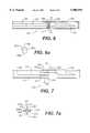
- FIG. 6is an enlarged broken side elevation view in partial section of the distal end of a second embodiment of an infusion needle device according to the invention.
- FIG. 6ais a cross sectional view taken along line 6A--6A in FIG. 6;
- FIG. 7is an enlarged broken side elevation view in partial section of the distal end of a third embodiment of an infusion needle device according to the invention.
- FIG. 7ais a cross sectional view taken along line 7A--7A in FIG. 7;
- FIG. 8is an enlarged broken side elevation view in partial section of the distal end of a fourth embodiment of an infusion needle device according to the invention.
- FIG. 8ais a cross sectional view taken along line 8A--8A in FIG. 8.
- an endoscopic infusion needle device 10includes a relatively long flexible catheter 12 having a proximal end 14, a distal end 16, and defining a lumen 18.
- the catheter 12is a steel coil covered with a PTFE, FEP or polyolefin sheath 20 along substantially its entire length.
- a flexible, preferably metallic injection tube 22having a proximal end 24, a distal end 26, and defining an injection lumen 28 is slideably disposed within the lumen 18 of the catheter 12 and defines an annular space 19 between the tube 22 and the catheter 12.
- the distal end 26 of the injection tube 22is provided with an injection needle 30 which is in fluid communication with the injection lumen 28 of the injection tube 22.
- the proximal ends 14, 24 of the catheter and the injection tubeare coupled to an actuation handle 32 which includes a central shaft 34 and a displaceable spool 36.
- the proximal end of the shaft 34is provided with a thumb ring 38 and a longitudinal bore 40 is provided at the distal end of the shaft 34.
- a longitudinal slot 42extends from the proximal end of bore 40 to a point distal of the thumb ring 38.
- the displaceable spool 36is provided with a cross member 44 which passes through the slot 42 in the central shaft 34.
- the proximal end 14 of the catheter 12is coupled to the cross member 44 which is provided with a fluid conduit 46 terminating in a luer connector 48.
- the fluid conduit 46provides a fluid path from the luer 48 to the lumen 18 of the catheter 12.
- the proximal end 24 of the injection tube 22is coupled to a proximal portion 50 of the shaft 34 which is intermediate of the thumb ring 38 and the slot 42.
- the portion 50is provided with a fluid conduit 52 terminating in a luer connector 54 which provides a fluid path from the luer to the injection lumen 28 of the injection tube 22.
- a source of irrigating fluidmay be coupled to the luer 48 and the irrigating fluid will be directed through the lumen 18 of the catheter in the annular space defined by the injection tube 22 and the catheter 12 and will exit from the distal end of the catheter.
- a source of injection fluidmay be coupled to the luer 54 and the injection fluid will be directed through the lumen 28 of the injection tube and will exit from the distal end of the injection needle 30.
- a distal portion of the catheter 12is provided with a rigid elongate skeletal structure 60 which is inserted in the distal end of the catheter 12 and which occupies a portion of the annular space between the injection tube 22 and the catheter 12.
- a distal portion of the injection tube 22 or a proximal portion of the injection needle 30is provided with an annular band 62 which resides within the skeletal structure 60.
- the skeletal structure 60is dimensioned such that it fits tightly within the catheter 12, allows irrigation fluid to pass through the annular space between the injection tube 22 and the catheter 12 and to exit the distal end of the catheter, and prevents the annular band 62 from escaping through the proximal end or the distal end of the skeletal structure 60.
- the skeletal structureis dimensioned to maintain the injection tube 22 and the needle 30 in substantial axial alignment with the catheter 12.
- the annular band 62is located such that when the injection tube is moved proximally relative to the catheter, as shown in FIG. 2, the distal end of the injection needle 30 is safely housed within the skeletal structure when the annular band 62 is stopped by the skeletal structure.
- the distal end of the injection needleextends approximately 4-6 mm beyond the distal end of the skeletal structure 60 when the annular band 62 is stopped by the skeletal structure.
- the skeletal structure 60includes a proximal cylindrical member 64, a distal cylindrical member 66, and four longitudinal outer struts or splines 68, 70, 72, 74 which connect the cylindrical members 64, 66.
- the strutsare arranged at regular intervals around the outer surfaces of the cylindrical members and are intended to center the cylindrical members 64, 66 while providing a fluid flow path.
- the struts 68, 70, 72, 74are preferably provided with stepped distal portions 68a, 70a, 72a, 74a which rise abruptly and form a seat for receiving the distal end of the catheter 12 and then curve inward to form a smooth distal end.
- the skeletal structure 60is formed from two identical members 60a, 60b with mating pegs 61a, 61b, 67a, 67b and holes 65a, 65b, 69a, 69b, and which are bonded together.
- the diameter of the proximal cylindrical member 64 of the skeletal structure 60is large enough to allow free passage of the injection tube 22, but too small to allow the passage of the annular band 62.
- the diameter of the distal cylindrical member 66is large enough to allow free passage of the injection needle 30, but too small to allow the passage of the annular band 62.
- the diameter of the injection tube 22is approximately 0.028 inches; the diameter of the injection needle is approximately 0.020 inches (25G); and the diameter of the annular band is approximately 0.035 inches. The space between the struts is sufficient to allow passage of irrigant through the distal end of the catheter.
- the skeletal structure 60 and the annular band 62provide a positive well-defined proximal stopping location (FIG. 2) and a positive well-defined distal stopping location (FIG. 3) for the injection needle 30.
- the skeletal structureprovides an axial alignment for the injection needle 30 which prevents the needle from puncturing the catheter 12. While the first embodiment of the invention has been shown in conjunction with a coated steel coil catheter, it will be appreciated that other types of catheters could be used, such as flexible plastic catheters.
- FIGS. 6 and 6ashow a second embodiment 110 of the invention where parts similar to the first embodiment are indicated by similar reference numerals increased by 100.
- the distal end of the injection tube 122is provided with two spaced apart annular bands 162, 163.
- At least one stopping washer 160is placed between adjacent coils of the catheter 112 such that the washer(s) reside between the annular bands 162, 163.
- the stopping washer 160is substantially disk shaped with a radial cutout 160a and two side cutouts 160b, 160c.
- the radial cutout 160aWhen the washer 160 is inserted radially in between adjacent coils of the catheter 112, the radial cutout 160a receives the injection tube 122 and the side cutouts 160b, 160c allow the passage of irrigant through the distal end of the catheter 112. It will be appreciated that the dimensions of the radial cutout 160a are such that the washer prevents distal passage of the proximal annular band 162 and prevents proximal passage of the distal annular band 163. Preferably two washers are used with their radial cutouts oriented in opposite directions to provide an axial alignment of the injection tube 122 with the catheter 112.
- the washer(s) 160 and the bands 162, 163cooperate to provide a positive well-defined proximal stopping location for the needle 130 wherein the needle is shrouded by the catheter 112 and a positive well-defined distal stopping location where the injection needle 130 extends approximately 4-6 mm out of the catheter 112.
- FIGS. 7 and 7ashow a third embodiment 210 of the invention where parts similar to the first embodiment are indicated by similar reference numerals increased by 200.
- the third embodiment of the inventionis preferably used with a plastic catheter.
- the distal end of the injection tube 222is provided with two spaced apart annular bands 262, 263.
- a strutted barbed cylindrical stop 260is pressed into the distal end of the catheter 212 such that the stop resides between the annular bands 262, 263.
- the stop 260has a central cylinder 264 with four outer struts 268, 270, 272, 274.
- each strutis provided with barbs 268a, 270a, 272a, 274a.
- the barbed strutsengage the interior of the catheter after several hours of cold setting.
- the cathetermay be dilated with heat before inserting the stop.
- the dimensions of the cylinder 264are such that it prevents distal passage of the proximal annular band 262 and prevents proximal passage of the distal annular band 263.
- the struts 268, 270, 272, 274are dimensioned and arranged to allow free passage of irrigant through the distal end of the catheter.
- stop 260 and the bands 262, 263cooperate to provide a positive well-defined proximal stopping location for the needle 230 wherein the needle is shrouded by the catheter 212 and a positive well-defined distal stopping location where the injection needle 230 extends approximately 4-6 mm out of the catheter 212.
- FIGS. 8 and 8ashow a fourth embodiment 310 of the invention where parts similar to the first embodiment are indicated by similar reference numerals increased by 300.
- the fourth embodiment of the inventionis shown with a plastic catheter 312, but may be used with any type of catheter.
- the distal end of the injection tube 322is provided with two spaced apart annular bands 362, 363 and a distal stopping structure 360 is inserted into the distal end of the catheter 312.
- the stopping structurehas a proximal inner cylinder 364 and an outer cylinder 366 having a reduced diameter proximal portion 366a which fits into the distal end of the catheter 312.
- the proximal inner cylinder 364is coupled to the outer cylinder by four radial struts 368, 370, 372, 374 which define four longitudinal fluid paths 368a, 370a, 372a, 374a between the inner cylinder 364 and the outer cylinder 366.
- the diameter of the inner cylinder 364is such that it prevents distal passage of the proximal annular band 362 and prevents proximal passage of the distal annular band 363.
- the reduced diameter portion 366a of the outer cylinderis solvent bonded to the catheter.
- the reduced diameter portion 366amay be provided with outer threads (not shown) to engage the coils of the catheter.
- the length of the outer cylinder 366 and the location of the bands 362, 364are chosen so that the inner cylinder and the bands cooperate to provide a positive well-defined proximal stopping location for the needle 330 wherein the needle is shrouded by the outer cylinder 360 and a positive well-defined distal stopping location where the injection needle 330 extends approximately 4-6 mm out of the outer cylinder 360.
- stopping structureshas been described as an annular band, it will be appreciated that other types of surface structures such as bumps or struts could be used.
- devicehas been disclosed as having specific dimensions, it will be understood that other dimensions can achieve the same or similar function as disclosed herein.
Landscapes
- Health & Medical Sciences (AREA)
- Life Sciences & Earth Sciences (AREA)
- Veterinary Medicine (AREA)
- Public Health (AREA)
- Engineering & Computer Science (AREA)
- Surgery (AREA)
- Biomedical Technology (AREA)
- Heart & Thoracic Surgery (AREA)
- General Health & Medical Sciences (AREA)
- Animal Behavior & Ethology (AREA)
- Hematology (AREA)
- Pulmonology (AREA)
- Biophysics (AREA)
- Pathology (AREA)
- Nuclear Medicine, Radiotherapy & Molecular Imaging (AREA)
- Anesthesiology (AREA)
- Medical Informatics (AREA)
- Molecular Biology (AREA)
- Infusion, Injection, And Reservoir Apparatuses (AREA)
Abstract
Description
1. Field of the Invention
The invention relates to endoscopic medical devices. More particularly, the invention relates to an endoscopic infusion device having a needle which is movable within an outer tube from a first position to a second position.
2. State of the Art
Endoscopic infusion needle devices are used in the treatment of various digestive disorders to control bleeding or potential bleeding lesions in the esophagus, stomach, duodenum, and colon. The state of the art devices include a relatively long catheter, typically having an overall length of about 200 cm, within which an inner injection tube having a distal injection needle is slideably disposed. A proximal actuating handle is coupled to the catheter and the injection tube for moving one relative to the other. Fluid access to the injection tube is typically provided via a luer connector on the handle. In addition, a second luer connector is usually provided on the handle for introducing a saline irrigant into the annular space between the catheter and the injection tube.
Endoscopic infusion needle devices are typically delivered to an injection site through the lumen of an endoscope. In order to protect the lumen of the endoscope from damage, the handle of the infusion needle device is manipulated to withdraw the distal injection needle into the lumen of the catheter before inserting the device into the endoscope. This is important to prevent exposure of the sharp point of the injection needle as the device is moved through the lumen of the endoscope. When the distal end of the infusion needle device is located at the injection site, its handle is again manipulated to move the injection needle distally out of the lumen of the catheter. When advanced to the most distal position, the exposed portion of the injection needle should be approximately 4-6 mm in length. The injection procedure is often preceded by washing the site with saline in order to clear the field of view before piercing the injection site with the needle. The saline wash is delivered via the annular space between the catheter and the injection tube. After the injection site has been pierced, a sclerosing agent or vasoconstrictor composition is delivered through the injection tube and the needle into the injection site. The procedure may be performed at several injection sites before the injection needle device is removed from the endoscope. Between injections, however, the needle is withdrawn into the catheter to prevent inadvertent punctures or needle pricks.
The state of the art endoscopic infusion needle devices all suffer from similar design problems which are related to the movement of the needle into and out of the catheter. For example, it is difficult to assure that the injection needle will remain within the catheter when it is withdrawn, or to assure that the injection needle will not puncture the wall of the catheter during movement of the device through the endoscope. The reason for these problems is related to the dimensions of the device and the often tortuous path provided by the lumen of the endoscope. As mentioned above, the desired relative movement of the needle and the catheter is only on the order of 10 mm, whereas the overall length of the device is on the order of two hundred times that amount. Thus, the movement of the proximal ends of the catheter and the injection tube by an amount on the order of 10 mm cannot assure that the distal ends of the catheter and the injection tube will move exactly the same amount without requiring exacting tolerances. This issue is exacerbated by the tortuous path taken through the endoscope by the device. This tortuous path also causes the injection needle to be deflected relative to the axis of the catheter such that the sharp point of the needle touches the inner wall of the catheter. As the device is moved through the endoscope, it is thereby possible for the injection needle to puncture the catheter wall, rendering the device inoperative, and possibly damaging the lumen of the endoscope.
It is therefore an object of the invention to provide an endoscopic infusion needle device which assures that the distal ends of the catheter and the injection tube can be moved relative to each other between two well-defined positions.
It is also an object of the invention to provide an endoscopic infusion needle device which assures that the sharp end of the injection needle will not contact the inner wall of the catheter.
It is another object of the invention to provide an endoscopic infusion needle device which is inexpensive to manufacture.
It is still another object of the invention to provide an endoscopic infusion needle device which does not require exacting tolerances to assure the well-defined positions of the catheter and the injection tube.
In accord with these objects which will be discussed in detail below, the endoscopic infusion needle device of the present invention includes a relatively long catheter within which an inner injection tube having a distal injection needle is slideably disposed. A proximal actuating handle is coupled to the proximal ends of the catheter and the injection tube for moving one relative to the other, and distal stopping structures are provided on distal portions of the catheter and the injection tube. Fluid access to the injection tube is provided via a luer connector on the handle, and a second luer connector is provided on the handle for introducing a saline irrigant into the annular space between the catheter and the injection tube. According to one embodiment of the invention, the distal stopping structures include a rigid elongate skeletal structure which is inserted into the distal end of the catheter and which occupies a portion of the annular space between the injection tube and the catheter wall, and an annular band on a portion of the injection tube which resides within the skeletal structure. The skeletal structure is dimensioned such that it fits tightly within the cannula, allows irrigation fluid to pass through the annular space between the injection tube and the catheter and to exit the distal end of the catheter, and prevents the annular band from escaping through the proximal end or the distal end of the skeletal structure. In addition, the skeletal structure is dimensioned to maintain the injection needle in substantial axial alignment with the catheter. The annular band is located on the injection tube such that when the injection tube is moved proximally relative to the catheter, the distal end of the injection needle is safely housed within the skeletal structure when the annular band is stopped by the skeletal structure; and, when the injection tube is moved distally relative to the catheter, the distal end of the injection needle extends approximately 4-6 mm beyond the distal end of the skeletal structure when the annular band is stopped by the skeletal structure. According to other embodiments of the invention, two annular bands are provided on the injection tube and one or more stopping structures are provided within the cannula.
The distal stopping structure according to the invention provides a positive well-defined proximal stopping location and a positive well-defined distal stopping location for the injection needle. In addition, several embodiments of the stopping structure provide an axial alignment for the injection needle which prevents the needle from puncturing the catheter.
Additional objects and advantages of the invention will become apparent to those skilled in the art upon reference to the detailed description taken in conjunction with the provided figures.
FIG. 1 is a broken side elevation view in partial section of a first embodiment of an endoscopic infusion needle device according to the invention;
FIG. 2 is an enlarged broken side elevation view in partial section of the distal end of the infusion needle device of FIG. 1 in a retracted position;
FIG. 3 is an enlarged broken side elevation view in partial section of the distal end of the infusion needle device of FIG. 1 in an extended position;
FIG. 4 is a perspective view of the coil stiffening and needle stopping structure of the infusion needle device of FIGS. 1-3;
FIG. 5 is an exploded perspective view of the coil stiffening and needle stopping structure of the infusion needle device of FIGS. 1-3;
FIG. 6 is an enlarged broken side elevation view in partial section of the distal end of a second embodiment of an infusion needle device according to the invention;
FIG. 6a is a cross sectional view taken along line 6A--6A in FIG. 6;
FIG. 7 is an enlarged broken side elevation view in partial section of the distal end of a third embodiment of an infusion needle device according to the invention;
FIG. 7a is a cross sectional view taken along line 7A--7A in FIG. 7;
FIG. 8 is an enlarged broken side elevation view in partial section of the distal end of a fourth embodiment of an infusion needle device according to the invention; and
FIG. 8a is a cross sectional view taken along line 8A--8A in FIG. 8.
Referring now to FIGS. 1 through 3, an endoscopicinfusion needle device 10 according to the invention includes a relatively longflexible catheter 12 having a proximal end 14, adistal end 16, and defining alumen 18. As shown, thecatheter 12 is a steel coil covered with a PTFE, FEP orpolyolefin sheath 20 along substantially its entire length. A flexible, preferablymetallic injection tube 22 having aproximal end 24, adistal end 26, and defining aninjection lumen 28 is slideably disposed within thelumen 18 of thecatheter 12 and defines anannular space 19 between thetube 22 and thecatheter 12. Thedistal end 26 of theinjection tube 22 is provided with aninjection needle 30 which is in fluid communication with theinjection lumen 28 of theinjection tube 22.
The proximal ends 14, 24 of the catheter and the injection tube are coupled to anactuation handle 32 which includes acentral shaft 34 and adisplaceable spool 36. The proximal end of theshaft 34 is provided with athumb ring 38 and alongitudinal bore 40 is provided at the distal end of theshaft 34. Alongitudinal slot 42 extends from the proximal end ofbore 40 to a point distal of thethumb ring 38. Thedisplaceable spool 36 is provided with across member 44 which passes through theslot 42 in thecentral shaft 34. The proximal end 14 of thecatheter 12 is coupled to thecross member 44 which is provided with afluid conduit 46 terminating in aluer connector 48. Thefluid conduit 46 provides a fluid path from theluer 48 to thelumen 18 of thecatheter 12. An O-ring 49 in thecross member 44, proximal of thefluid conduit 46, seals the annulus between thecatheter 12 and theinjection tube 22. Theproximal end 24 of theinjection tube 22 is coupled to aproximal portion 50 of theshaft 34 which is intermediate of thethumb ring 38 and theslot 42. Theportion 50 is provided with afluid conduit 52 terminating in aluer connector 54 which provides a fluid path from the luer to theinjection lumen 28 of theinjection tube 22.
From the foregoing, those skilled in the art will appreciate that when thethumb ring 38 and thespool 36 are moved toward each other, theinjection tube 22 will be axially displaced relative to thecatheter 12 such that theneedle 30 extends out of the distal end of thecatheter 12 as shown in FIG. 3. When thethumb ring 38 and thespool 36 are moved away from each other, theinjection tube 22 will be axially displaced relative to thecatheter 12 such that theneedle 30 is drawn into the distal end of thecatheter 12 as shown in FIGS. 1 and 2. Furthermore, it will be appreciated that a source of irrigating fluid (not shown) may be coupled to theluer 48 and the irrigating fluid will be directed through thelumen 18 of the catheter in the annular space defined by theinjection tube 22 and thecatheter 12 and will exit from the distal end of the catheter. In addition, it will be appreciated that a source of injection fluid (not shown) may be coupled to theluer 54 and the injection fluid will be directed through thelumen 28 of the injection tube and will exit from the distal end of theinjection needle 30.
According to a first embodiment of the invention, a distal portion of thecatheter 12 is provided with a rigid elongateskeletal structure 60 which is inserted in the distal end of thecatheter 12 and which occupies a portion of the annular space between theinjection tube 22 and thecatheter 12. A distal portion of theinjection tube 22 or a proximal portion of theinjection needle 30 is provided with anannular band 62 which resides within theskeletal structure 60. As described in more detail below with reference to FIGS. 4 and 5, theskeletal structure 60 is dimensioned such that it fits tightly within thecatheter 12, allows irrigation fluid to pass through the annular space between theinjection tube 22 and thecatheter 12 and to exit the distal end of the catheter, and prevents theannular band 62 from escaping through the proximal end or the distal end of theskeletal structure 60. In addition, the skeletal structure is dimensioned to maintain theinjection tube 22 and theneedle 30 in substantial axial alignment with thecatheter 12. Theannular band 62 is located such that when the injection tube is moved proximally relative to the catheter, as shown in FIG. 2, the distal end of theinjection needle 30 is safely housed within the skeletal structure when theannular band 62 is stopped by the skeletal structure. When theinjection tube 22 is moved distally relative to thecatheter 12, as shown in FIG. 3, the distal end of the injection needle extends approximately 4-6 mm beyond the distal end of theskeletal structure 60 when theannular band 62 is stopped by the skeletal structure.
Turning now to FIGS. 4 and 5, according to a presently preferred embodiment, theskeletal structure 60 includes a proximalcylindrical member 64, a distalcylindrical member 66, and four longitudinal outer struts or splines 68, 70, 72, 74 which connect thecylindrical members cylindrical members struts distal portions catheter 12 and then curve inward to form a smooth distal end. According to the presently preferred embodiment, theskeletal structure 60 is formed from twoidentical members mating pegs holes
Referring once again to FIGS. 2 and 3, and in view of the foregoing, it will be appreciated that the diameter of the proximalcylindrical member 64 of theskeletal structure 60 is large enough to allow free passage of theinjection tube 22, but too small to allow the passage of theannular band 62. Similarly, the diameter of the distalcylindrical member 66 is large enough to allow free passage of theinjection needle 30, but too small to allow the passage of theannular band 62. According to a presently preferred embodiment, the diameter of theinjection tube 22 is approximately 0.028 inches; the diameter of the injection needle is approximately 0.020 inches (25G); and the diameter of the annular band is approximately 0.035 inches. The space between the struts is sufficient to allow passage of irrigant through the distal end of the catheter.
From the foregoing and with reference to FIGS. 1-5, generally, it will be appreciated that theskeletal structure 60 and theannular band 62 provide a positive well-defined proximal stopping location (FIG. 2) and a positive well-defined distal stopping location (FIG. 3) for theinjection needle 30. In addition, the skeletal structure provides an axial alignment for theinjection needle 30 which prevents the needle from puncturing thecatheter 12. While the first embodiment of the invention has been shown in conjunction with a coated steel coil catheter, it will be appreciated that other types of catheters could be used, such as flexible plastic catheters.
FIGS. 6 and 6a show asecond embodiment 110 of the invention where parts similar to the first embodiment are indicated by similar reference numerals increased by 100. According to the second embodiment, the distal end of the injection tube 122 is provided with two spaced apartannular bands washer 160 is placed between adjacent coils of thecatheter 112 such that the washer(s) reside between theannular bands washer 160 is substantially disk shaped with aradial cutout 160a and twoside cutouts washer 160 is inserted radially in between adjacent coils of thecatheter 112, theradial cutout 160a receives the injection tube 122 and theside cutouts catheter 112. It will be appreciated that the dimensions of theradial cutout 160a are such that the washer prevents distal passage of the proximalannular band 162 and prevents proximal passage of the distalannular band 163. Preferably two washers are used with their radial cutouts oriented in opposite directions to provide an axial alignment of the injection tube 122 with thecatheter 112. From the foregoing, those skilled in the art will appreciate that the washer(s) 160 and thebands needle 130 wherein the needle is shrouded by thecatheter 112 and a positive well-defined distal stopping location where theinjection needle 130 extends approximately 4-6 mm out of thecatheter 112.
FIGS. 7 and 7a show athird embodiment 210 of the invention where parts similar to the first embodiment are indicated by similar reference numerals increased by 200. The third embodiment of the invention is preferably used with a plastic catheter. According to the third embodiment, the distal end of theinjection tube 222 is provided with two spaced apartannular bands cylindrical stop 260 is pressed into the distal end of thecatheter 212 such that the stop resides between theannular bands stop 260 has acentral cylinder 264 with fourouter struts barbs stop 260 is inserted axially into the distal end of thecatheter 212, the barbed struts engage the interior of the catheter after several hours of cold setting. Alternatively, the catheter may be dilated with heat before inserting the stop. It will be appreciated that the dimensions of thecylinder 264 are such that it prevents distal passage of the proximalannular band 262 and prevents proximal passage of the distalannular band 263. Thestruts stop 260 and thebands needle 230 wherein the needle is shrouded by thecatheter 212 and a positive well-defined distal stopping location where theinjection needle 230 extends approximately 4-6 mm out of thecatheter 212.
FIGS. 8 and 8a show afourth embodiment 310 of the invention where parts similar to the first embodiment are indicated by similar reference numerals increased by 300. The fourth embodiment of the invention is shown with aplastic catheter 312, but may be used with any type of catheter. According to the fourth embodiment, the distal end of theinjection tube 322 is provided with two spaced apartannular bands distal stopping structure 360 is inserted into the distal end of thecatheter 312. The stopping structure has a proximalinner cylinder 364 and anouter cylinder 366 having a reduced diameterproximal portion 366a which fits into the distal end of thecatheter 312. The proximalinner cylinder 364 is coupled to the outer cylinder by fourradial struts longitudinal fluid paths inner cylinder 364 and theouter cylinder 366. The diameter of theinner cylinder 364 is such that it prevents distal passage of the proximalannular band 362 and prevents proximal passage of the distalannular band 363. When used with a plastic catheter, the reduceddiameter portion 366a of the outer cylinder is solvent bonded to the catheter. When used with a steel coil catheter, the reduceddiameter portion 366a may be provided with outer threads (not shown) to engage the coils of the catheter. The length of theouter cylinder 366 and the location of thebands needle 330 wherein the needle is shrouded by theouter cylinder 360 and a positive well-defined distal stopping location where theinjection needle 330 extends approximately 4-6 mm out of theouter cylinder 360.
There have been described and illustrated herein several embodiments of an endoscopic infusion needle device. While particular embodiments of the invention have been described, it is not intended that the invention be limited thereto, as it is intended that the invention be as broad in scope as the art will allow and that the specification be read likewise. Thus, while particular types of catheters have been disclosed, it will be appreciated that other catheters could be utilized. Also, while several specific distal stopping structures have been shown, it will be recognized that other types of distal stopping structures could be used with similar results obtained. Moreover, while particular configurations have been disclosed in reference to the proximal handle, it will be appreciated that other configurations could be used as well. In addition, while certain structures have been identified as being cylindrical, it will be understood than a substantially cylindrical structure can achieve the same results. Similarly, while one of the stopping structures has been described as an annular band, it will be appreciated that other types of surface structures such as bumps or struts could be used. Furthermore, while the device has been disclosed as having specific dimensions, it will be understood that other dimensions can achieve the same or similar function as disclosed herein.
It will therefore be appreciated by those skilled in the art that yet other modifications could be made to the provided invention without deviating from its spirit and scope as so claimed.
Claims (21)
1. An endoscopic infusion needle device, comprising:
a) a catheter having a proximal end, a distal end, and defining a first lumen;
b) an injection tube having a proximal end, a distal end, and defining a second lumen, said injection tube extending at least partially through said first lumen and defining an annular space between said injection tube and said catheter;
c) an injection needle coupled to said distal end of said injection tube, said injection needle having an injection lumen in fluid communication with said second lumen;
d) a proximal actuating means coupled to said proximal end of said catheter and to said proximal end of said injection tube for axially displacing said catheter and said injection tube relative to one another;
e) injection fluid port means coupled to said second lumen for introducing an injection fluid into said injection lumen;
f) a first distal stopping structure coupled to a distal portion of said catheter, wherein at least a portion of the first distal stopping structure extends within the catheter lumen; and
g) a second distal stopping structure coupled to at least one of said injection tube and said injection needle, wherein at least a portion of said second distal stopping structure is moveable with the injection tube and needle within the catheter lumen, and wherein
said first and second distal stopping structures cooperate with one another to provide a positive well-defined proximal stopping location wherein said injection needle is shrouded by said catheter, and to provide a positive well-defined distal stopping location wherein said injection needle extends out of said catheter.
2. An endoscopic infusion needle device according to claim 1, wherein:
said first distal stopping structure includes at least one substantially cylindrical member having a plurality of substantially radial exterior struts, said at least one substantially cylindrical member being arranged inside said first lumen such that said struts engage said catheter and at least one of said injection tube and said injection needle passes through said at least one substantially cylindrical member, and
said second distal stopping structure includes at least one annular structure coupled to one of said injection tube and said injection needle.
3. An endoscopic infusion needle device according to claim 2, wherein:
said first distal stopping structure includes two substantially cylindrical members having a plurality of substantially radial exterior struts, said two substantially cylindrical members being arranged inside said first lumen such that one of said injection tube and said injection needle passes through said two substantially cylindrical member and said struts engage said catheter, and
said at least one annular structure resides in between said two substantially cylindrical members.
4. An endoscopic infusion needle device according to claim 3, wherein:
said two substantially cylindrical members are coupled to each other by a plurality of splines.
5. An endoscopic infusion needle device according to claim 4, wherein:
said first distal stopping structure extends partially out of said distal end of said catheter.
6. An endoscopic infusion needle device according to claim 5, wherein:
said first distal stopping structure has a smooth distal end.
7. An endoscopic infusion needle device according to claim 4, wherein:
said first distal stopping structure is made of two identical pieces.
8. An endoscopic infusion needle device according to claim 1, wherein:
said second distal stopping structure includes two annular structures, each coupled to one of said injection tube and said injection needle, and
said first distal stopping structure resides in between said two annular structures.
9. An endoscopic infusion needle device according to claim 8, wherein:
said first distal stopping structure includes a substantially cylindrical member having a plurality of outer struts.
10. An endoscopic infusion needle device according to claim 9, wherein:
said struts include outwardly extending barbs.
11. An endoscopic infusion needle device according to claim 9, wherein:
said struts are arranged substantially radially relative to said substantially cylindrical member.
12. An endoscopic infusion needle device according to claim 8, wherein:
said first distal stopping structure includes a washer having a radial opening.
13. An endoscopic infusion needle device according to claim 1, further comprising:
h) irrigation fluid port means coupled to said first lumen for introducing an irrigant into said annular space, wherein
said first and second distal stopping structures permit said irrigant to flow out of said distal end of said catheter.
14. An endoscopic infusion needle device, comprising:
a) a catheter having a proximal end, a distal end, and defining a first lumen;
b) an injection tube having a proximal end, a distal end, and defining a second lumen, said injection tube extending at least partially through said first lumen and defining an annular space between said injection tube and said catheter;
c) an injection needle coupled to said distal end of said injection tube, said injection needle having an injection lumen in fluid communication with said second lumen;
d) a proximal actuating means coupled to said proximal end of said catheter and to said proximal end of said injection tube for axially displacing said catheter and said injection tube relative to one another;
e) injection fluid port means coupled to said second lumen for introducing an injection fluid into said injection lumen;
f) a first distal stopping structure coupled to a distal portion of said catheter, said first distal stopping structure having a first substantially cylindrical portion extending beyond said distal end of said catheter, wherein at least a portion of the first distal stopping structure extends within the catheter lumen; and
g) a second distal stopping structure coupled to at least one of said injection tube and said injection needle, wherein at least a portion of said second distal stopping structure is moveable with the injection tube and needle within the catheter lumen, and wherein
said first and second distal stopping structures cooperate with one another to provide a positive well-defined proximal stopping location wherein said injection needle is shrouded by said first substantially cylindrical portion, and to provide a positive well-defined distal stopping location wherein said injection needle extends out of said first substantially cylindrical portion.
15. An endoscopic infusion needle device according to claim 14, wherein:
said first distal stopping structure includes a second substantially cylindrical portion residing within said first substantially cylindrical portion and coupled to said first substantially cylindrical portion by a plurality of struts,
one said injection tube and said injection needle extending through said second substantially cylindrical portion.
16. An endoscopic infusion needle device according to claim 15, wherein:
said second distal stopping structure includes at least one annular structure coupled to one of said injection tube and said injection needle.
17. An endoscopic infusion needle device according to claim 15, wherein:
said second distal stopping structure includes two annular structures, each coupled to one of said injection tube and said injection needle,
said second substantially cylindrical portion residing in between said two annular structures.
18. An endoscopic infusion needle device, comprising:
a) a catheter having a proximal end, a distal end, and defining a first lumen;
b) an injection tube having a proximal end, a distal end, and defining a second lumen, said injection tube extending at least partially through said first lumen and defining an annular space between said injection tube and said catheter;
c) an injection needle coupled to said distal end of said injection tube, said injection needle having an injection lumen in fluid communication with said second lumen;
d) a proximal actuating means coupled to said proximal end of said catheter and to said proximal end of said injection tube for axially displacing said catheter and said injection tube relative to one another;
e) injection fluid port means coupled to said second lumen for introducing an injection fluid into said injection lumen;
f) a centering structure coupled to a distal portion of said catheter, wherein
said centering structure maintains said injection needle in substantial axial alignment with said distal portion of said catheter during movement of said injection needle within said first lumen, wherein
said centering structure includes means for limiting a range of motion of said injection needle relative to said catheter between a first position wherein said injection needle is shrouded by said centering structure to a second position wherein said injection needle extends distally beyond said centering structure, and
wherein the means for limiting a range of motion includes a first stopping structure attached to a portion of the needle and moveable with said needle within said first lumen of said catheter.
19. An endoscopic needle device according to claim 18, wherein:
said centering structure includes a substantially rigid structure, and
wherein said injection needle is shrouded by said substantially rigid structure in said first position, and said injection needle extends distally beyond said substantially rigid structure in said second position.
20. An endoscopic needle device according to claim 19, wherein:
said centering structure further includes a second stopping structure for engaging the first stopping structure attached to the needle in order to provide a positive stop at at least one of said first and second positions.
21. An endoscopic infusion needle device, comprising:
a) a catheter having a proximal end, a distal end, and defining a first lumen;
b) an injection tube having a proximal end, a distal end, and defining a second lumen, said injection tube extending at least partially through said first lumen and defining an annular space between said injection tube and said catheter;
c) an injection needle coupled to said distal end of said injection tube, said injection needle having an injection lumen in fluid communication with said second lumen;
d) a proximal actuating means coupled to said proximal end of said catheter and to said proximal end of said injection tube for axially displacing said catheter and said injection tube relative to one another;
e) a first distal stopping structure including at least one substantially cylindrical member having a plurality of substantially radial exterior struts, wherein said first distal stopping structure is coupled to a distal portion of said catheter and said at least one substantially cylindrical member extends within the first lumen such that said struts engage the catheter and at least one of said injection tube and said injection needle passes through said at least one substantially cylindrical member; and
f) a second distal stopping structure including at least one annular structure coupled to at least one of said injection tube and said injection needle, wherein
said first and second distal stopping structures cooperate with one another to provide a positive well-defined proximal stopping location wherein said injection needle is shrouded by said catheter, and to provide a positive well-defined distal stopping location wherein said injection needle extends out of said catheter.
Priority Applications (13)
| Application Number | Priority Date | Filing Date | Title |
|---|---|---|---|
| US08/778,243US5906594A (en) | 1997-01-08 | 1997-01-08 | Endoscopic infusion needle having dual distal stops |
| IL15576698AIL155766A0 (en) | 1997-01-08 | 1998-01-07 | Endoscopic infusion needle and system |
| DE69838725TDE69838725T2 (en) | 1997-01-08 | 1998-01-07 | Endoscope fusion needle with double stop |
| AU60207/98AAU742340B2 (en) | 1997-01-08 | 1998-01-07 | Endoscopic infusion needle having dual distal stops |
| JP53117198AJP4680328B2 (en) | 1997-01-08 | 1998-01-07 | Endoscopic needle with two stops on the distal part |
| IL13086998AIL130869A (en) | 1997-01-08 | 1998-01-07 | Endoscopic infusion needle having dual distal stopping positions |
| EP98903436AEP1011756B1 (en) | 1997-01-08 | 1998-01-07 | Endoscopic infusion needle having dual distal stops |
| CA002277033ACA2277033A1 (en) | 1997-01-08 | 1998-01-07 | Endoscopic infusion needle having dual distal stops |
| PCT/US1998/000484WO1998030259A1 (en) | 1997-01-08 | 1998-01-07 | Endoscopic infusion needle having dual distal stops |
| US09/289,539US6336915B1 (en) | 1997-01-08 | 1999-04-12 | Endoscopic infusion needle having dual distal stops |
| US09/964,603US6423034B2 (en) | 1997-01-08 | 2001-09-28 | Endoscopic infusion needle having dual distal stops |
| US10/193,271US6770053B2 (en) | 1997-01-08 | 2002-07-12 | Endoscopic needle having dual distal stops |
| IL155766AIL155766A (en) | 1997-01-08 | 2003-05-05 | Endoscopic infusion needle and a system including said needle |
Applications Claiming Priority (1)
| Application Number | Priority Date | Filing Date | Title |
|---|---|---|---|
| US08/778,243US5906594A (en) | 1997-01-08 | 1997-01-08 | Endoscopic infusion needle having dual distal stops |
Related Child Applications (1)
| Application Number | Title | Priority Date | Filing Date |
|---|---|---|---|
| US09/289,539ContinuationUS6336915B1 (en) | 1997-01-08 | 1999-04-12 | Endoscopic infusion needle having dual distal stops |
Publications (1)
| Publication Number | Publication Date |
|---|---|
| US5906594Atrue US5906594A (en) | 1999-05-25 |
Family
ID=25112724
Family Applications (4)
| Application Number | Title | Priority Date | Filing Date |
|---|---|---|---|
| US08/778,243Expired - LifetimeUS5906594A (en) | 1997-01-08 | 1997-01-08 | Endoscopic infusion needle having dual distal stops |
| US09/289,539Expired - LifetimeUS6336915B1 (en) | 1997-01-08 | 1999-04-12 | Endoscopic infusion needle having dual distal stops |
| US09/964,603Expired - LifetimeUS6423034B2 (en) | 1997-01-08 | 2001-09-28 | Endoscopic infusion needle having dual distal stops |
| US10/193,271Expired - Fee RelatedUS6770053B2 (en) | 1997-01-08 | 2002-07-12 | Endoscopic needle having dual distal stops |
Family Applications After (3)
| Application Number | Title | Priority Date | Filing Date |
|---|---|---|---|
| US09/289,539Expired - LifetimeUS6336915B1 (en) | 1997-01-08 | 1999-04-12 | Endoscopic infusion needle having dual distal stops |
| US09/964,603Expired - LifetimeUS6423034B2 (en) | 1997-01-08 | 2001-09-28 | Endoscopic infusion needle having dual distal stops |
| US10/193,271Expired - Fee RelatedUS6770053B2 (en) | 1997-01-08 | 2002-07-12 | Endoscopic needle having dual distal stops |
Country Status (8)
| Country | Link |
|---|---|
| US (4) | US5906594A (en) |
| EP (1) | EP1011756B1 (en) |
| JP (1) | JP4680328B2 (en) |
| AU (1) | AU742340B2 (en) |
| CA (1) | CA2277033A1 (en) |
| DE (1) | DE69838725T2 (en) |
| IL (2) | IL130869A (en) |
| WO (1) | WO1998030259A1 (en) |
Cited By (78)
| Publication number | Priority date | Publication date | Assignee | Title |
|---|---|---|---|---|
| US6120520A (en)* | 1997-05-27 | 2000-09-19 | Angiotrax, Inc. | Apparatus and methods for stimulating revascularization and/or tissue growth |
| US6251130B1 (en)* | 1998-03-24 | 2001-06-26 | Innercool Therapies, Inc. | Device for applications of selective organ cooling |
| US6423034B2 (en)* | 1997-01-08 | 2002-07-23 | Symbiosis Corporation | Endoscopic infusion needle having dual distal stops |
| US6432119B1 (en) | 1999-03-17 | 2002-08-13 | Angiotrax, Inc. | Apparatus and methods for performing percutaneous myocardial revascularization and stimulating angiogenesis using autologous materials |
| US20020151845A1 (en)* | 2000-12-06 | 2002-10-17 | Randell Werneth | Multipurpose catheter assembly |
| US6482226B1 (en) | 1998-01-23 | 2002-11-19 | Innercool Therapies, Inc. | Selective organ hypothermia method and apparatus |
| US6491039B1 (en) | 1998-01-23 | 2002-12-10 | Innercool Therapies, Inc. | Medical procedure |
| US6533804B2 (en) | 1998-01-23 | 2003-03-18 | Innercool Therapies, Inc. | Inflatable catheter for selective organ heating and cooling and method of using the same |
| US20030060863A1 (en)* | 1999-02-09 | 2003-03-27 | Dobak John D. | Method and apparatus for patient temperature control employing administration of anti-shivering agents |
| US6551349B2 (en) | 1998-03-24 | 2003-04-22 | Innercool Therapies, Inc. | Selective organ cooling apparatus |
| US20030078641A1 (en)* | 1998-01-23 | 2003-04-24 | Innercool Therapies, Inc. | Selective organ hypothermia method and apparatus |
| US6576001B2 (en) | 2000-03-03 | 2003-06-10 | Innercool Therapies, Inc. | Lumen design for catheter |
| US6576002B2 (en) | 1998-03-24 | 2003-06-10 | Innercool Therapies, Inc. | Isolated selective organ cooling method and apparatus |
| US6585752B2 (en) | 1998-06-23 | 2003-07-01 | Innercool Therapies, Inc. | Fever regulation method and apparatus |
| US6595967B2 (en) | 2001-02-01 | 2003-07-22 | Innercool Therapies, Inc. | Collapsible guidewire lumen |
| US6599312B2 (en) | 1998-03-24 | 2003-07-29 | Innercool Therapies, Inc. | Isolated selective organ cooling apparatus |
| US6602276B2 (en) | 1998-03-31 | 2003-08-05 | Innercool Therapies, Inc. | Method and device for performing cooling- or cryo-therapies for, e.g., angioplasty with reduced restenosis or pulmonary vein cell necrosis to inhibit atrial fibrillation |
| US20030171723A1 (en)* | 1998-06-04 | 2003-09-11 | Biosense Webster, Inc. | Injection catheter with multi-directional delivery injection needle |
| US20030195470A1 (en)* | 1998-06-04 | 2003-10-16 | Biosense Webster, Inc. | Injection catheter with needle stop |
| US6648906B2 (en) | 2000-04-06 | 2003-11-18 | Innercool Therapies, Inc. | Method and apparatus for regulating patient temperature by irrigating the bladder with a fluid |
| US6660028B2 (en) | 2000-06-02 | 2003-12-09 | Innercool Therapies, Inc. | Method for determining the effective thermal mass of a body or organ using a cooling catheter |
| US6676690B2 (en) | 1999-10-07 | 2004-01-13 | Innercool Therapies, Inc. | Inflatable heat transfer apparatus |
| US6676688B2 (en) | 1998-01-23 | 2004-01-13 | Innercool Therapies, Inc. | Method of making selective organ cooling catheter |
| US20040010231A1 (en)* | 2000-07-13 | 2004-01-15 | Leonhardt Howard J | Deployment system for myocardial cellular material |
| US20040019311A1 (en)* | 2000-12-21 | 2004-01-29 | Justin Crank | Infusion devices and method |
| US6685732B2 (en) | 1998-03-31 | 2004-02-03 | Innercool Therapies, Inc. | Method and device for performing cooling- or cryo-therapies for, e.g., angioplasty with reduced restenosis or pulmonary vein cell necrosis to inhibit atrial fibrillation employing microporous balloon |
| US6692471B2 (en)* | 2001-02-16 | 2004-02-17 | Medex, Inc. | Method and apparatus for safety catheter insertion device |
| US6692488B2 (en) | 1998-01-23 | 2004-02-17 | Innercool Therapies, Inc. | Apparatus for cell necrosis |
| US6702842B2 (en) | 1998-01-23 | 2004-03-09 | Innercool Therapies, Inc. | Selective organ cooling apparatus and method |
| US6712790B1 (en)* | 1998-12-31 | 2004-03-30 | Dean Brian Prestidge | Parenteral catheter apparatus |
| US6719779B2 (en) | 2000-11-07 | 2004-04-13 | Innercool Therapies, Inc. | Circulation set for temperature-controlled catheter and method of using the same |
| US6743206B1 (en)* | 2000-03-07 | 2004-06-01 | Syntheon, Llc | Endoscopic needle |
| US6830581B2 (en) | 1999-02-09 | 2004-12-14 | Innercool Therspies, Inc. | Method and device for patient temperature control employing optimized rewarming |
| US20050107668A1 (en)* | 1999-10-14 | 2005-05-19 | Scimed Life Systems, Inc. | Endoscopic instrument system having reduced backlash control wire action |
| US6905494B2 (en) | 1998-03-31 | 2005-06-14 | Innercool Therapies, Inc. | Method and device for performing cooling- or cryo-therapies for, e.g., angioplasty with reduced restenosis or pulmonary vein cell necrosis to inhibit atrial fibrillation employing tissue protection |
| US6905509B2 (en) | 1998-01-23 | 2005-06-14 | Innercool Therapies, Inc. | Selective organ cooling catheter with guidewire apparatus and temperature-monitoring device |
| US20050165412A1 (en)* | 2001-05-18 | 2005-07-28 | U.S. Endoscopy Group. Inc. | Retrieval device |
| US20050288695A1 (en)* | 2004-06-24 | 2005-12-29 | Scimed Life Systems, Inc. | Apparatus and method for treating occluded vasculature |
| US6991645B2 (en) | 1998-01-23 | 2006-01-31 | Innercool Therapies, Inc. | Patient temperature regulation method and apparatus |
| US20060025720A1 (en)* | 2003-05-06 | 2006-02-02 | Asahi Intecc Co., Ltd. | Medicinal-liquid injection apparatus |
| US7001378B2 (en) | 1998-03-31 | 2006-02-21 | Innercool Therapies, Inc. | Method and device for performing cooling or cryo-therapies, for, e.g., angioplasty with reduced restenosis or pulmonary vein cell necrosis to inhibit atrial fibrillation employing tissue protection |
| US7018399B2 (en) | 1998-06-23 | 2006-03-28 | Innercool Therapies, Inc. | Method of making selective organ cooling catheter |
| US20060178658A1 (en)* | 1999-10-14 | 2006-08-10 | Scimed Life Systems, Inc. | Endoscope and endoscopic instrument system having reduced backlash when moving the endoscopic instrument within a working channel of the endoscope |
| US7101386B2 (en) | 1998-01-23 | 2006-09-05 | Innercool Therapies, Inc. | Patient temperature regulation method and apparatus |
| US20070129706A1 (en)* | 2005-09-21 | 2007-06-07 | Osamu Katoh | Reagent injection apparatus and method of producing the same |
| US20070219461A1 (en)* | 2005-07-11 | 2007-09-20 | Tyco Healthcare Group Lp | Needle assembly including obturator with safety reset |
| US7291144B2 (en) | 1998-03-31 | 2007-11-06 | Innercool Therapies, Inc. | Method and device for performing cooling- or cryo-therapies for, e.g., angioplasty with reduced restenosis or pulmonary vein cell necrosis to inhibit atrial fibrillation |
| US20070299404A1 (en)* | 2004-10-19 | 2007-12-27 | Osamu Katoh | Reagent Injection Device |
| US20080004622A1 (en)* | 2006-06-29 | 2008-01-03 | Ethicon Endo-Surgery, Inc. | Band ligation and coagulation |
| US7371254B2 (en) | 1998-01-23 | 2008-05-13 | Innercool Therapies, Inc. | Medical procedure |
| US20080119869A1 (en)* | 2006-11-21 | 2008-05-22 | Boston Scientific Scimed, Inc. | Medical retrieval devices |
| US20080125709A1 (en)* | 2003-12-31 | 2008-05-29 | Gregory Waimong Chang | Needle catheter |
| US20080200377A1 (en)* | 2007-02-16 | 2008-08-21 | Trollsas Mikael O | Polymer particles |
| US7416547B2 (en) | 1999-03-29 | 2008-08-26 | Biosense Webster Inc. | Injection catheter |
| US7422600B2 (en) | 1999-02-09 | 2008-09-09 | Innercool Therapies, Inc. | Method and apparatus for patient temperature control employing administration of anti-shivering agents |
| US20080319314A1 (en)* | 1998-06-04 | 2008-12-25 | Biosense Webster, Inc. | Injection catheter |
| US20090118639A1 (en)* | 2007-11-01 | 2009-05-07 | Tyco Healthcare Group Lp | Active Stylet Safety Shield |
| US7654735B2 (en) | 2005-11-03 | 2010-02-02 | Covidien Ag | Electronic thermometer |
| US20100137835A1 (en)* | 2003-07-15 | 2010-06-03 | Leonhardt Howard J | Deployment system for myocardial cellular material |
| US7731692B2 (en) | 2005-07-11 | 2010-06-08 | Covidien Ag | Device for shielding a sharp tip of a cannula and method of using the same |
| US7850650B2 (en) | 2005-07-11 | 2010-12-14 | Covidien Ag | Needle safety shield with reset |
| US7857781B2 (en) | 1998-04-21 | 2010-12-28 | Zoll Circulation, Inc. | Indwelling heat exchange catheter and method of using same |
| US7905857B2 (en) | 2005-07-11 | 2011-03-15 | Covidien Ag | Needle assembly including obturator with safety reset |
| USRE43300E1 (en) | 1996-12-02 | 2012-04-03 | Abbott Cardiovascular Systems Inc. | Apparatus having stabilization members for percutaneously performing surgery and methods of use |
| EP1766476A4 (en)* | 2004-05-25 | 2012-07-04 | Us Endoscopy Group Inc | COLLET INJECTION DEVICE |
| US20120232570A1 (en)* | 2004-06-24 | 2012-09-13 | Boston Scientific Scimed, Inc. | Apparatus and method for treating occluded vasculature |
| USD687548S1 (en)* | 2011-05-31 | 2013-08-06 | Terumo Kabushiki Kaisha | Guidewire introducer needle |
| US20140221969A1 (en)* | 2013-01-31 | 2014-08-07 | Endochoice, Inc. | Endoscopic Injection Needle Device |
| US8834417B2 (en) | 2005-06-06 | 2014-09-16 | Covidien Ag | Needle assembly with removable depth stop |
| US8977344B2 (en) | 1998-06-04 | 2015-03-10 | Biosense Webster, Inc. | Injection catheter with needle electrode |
| USRE45638E1 (en) | 1996-12-02 | 2015-08-04 | Abbott Cardiovascular Systems Inc. | Apparatus for percutaneously performing myocardial revascularization having means for sensing tissue parameters and method of use |
| US9204888B2 (en) | 2007-06-08 | 2015-12-08 | United States Endoscopy Group, Inc. | Retrieval device |
| US10568628B2 (en) | 2017-05-23 | 2020-02-25 | Muffin Incorporated | Closing device for tissue openings |
| US10568614B2 (en) | 2010-04-29 | 2020-02-25 | Cook Medical Technologies Llc | Systems and methods for facilitating closure of bodily openings |
| US10667838B2 (en) | 2017-01-09 | 2020-06-02 | United States Endoscopy Group, Inc. | Endoscopic snare device |
| US10675053B2 (en) | 2013-09-03 | 2020-06-09 | United States Endoscopy Group, Inc. | Endoscopic snare device |
| US11253645B2 (en)* | 2014-10-29 | 2022-02-22 | Cedars-Sinai Medical Center | Apparatuses, systems and methods for controlled delivery of therapeutics and related substances |
| US11678792B2 (en)* | 2019-05-02 | 2023-06-20 | Karl Storz Se & Co. Kg | Endoscopic device |
Families Citing this family (65)
| Publication number | Priority date | Publication date | Assignee | Title |
|---|---|---|---|---|
| US6527748B1 (en)* | 1998-08-17 | 2003-03-04 | Yutaka Suzuki | Method of gastrostomy, and an infection preventive cover, kit or catheter kit, and a gastrostomy catheter kit |
| AU755356B2 (en)* | 1998-12-31 | 2002-12-12 | Dean Brian Prestidge | A parenteral catheter apparatus |
| US6478775B1 (en)* | 2000-10-02 | 2002-11-12 | Genyx Medical Inc. | Device for delivering non-biodegradable bulking composition to a urological site |
| US7160605B2 (en)* | 2002-04-12 | 2007-01-09 | Fusco Luciano A | Decorated panel and process for making the same |
| US6997903B2 (en)* | 2003-02-10 | 2006-02-14 | Bandula Wijay | Local drug delivery catheter |
| US7229433B2 (en)* | 2003-09-08 | 2007-06-12 | Mullen Gary J | Apparatus for treating pneumothorax and/or hemothorax |
| US7546089B2 (en)* | 2004-12-23 | 2009-06-09 | Triquint Semiconductor, Inc. | Switchable directional coupler for use with RF devices |
| JP4767655B2 (en)* | 2005-10-28 | 2011-09-07 | テルモ株式会社 | Protector and needle set |
| US7850686B2 (en) | 2006-03-30 | 2010-12-14 | Ethicon Endo-Surgery, Inc. | Protective needle knife |
| EP2037795A2 (en)* | 2006-07-10 | 2009-03-25 | Boston Scientific Limited | Optical spectroscopic injection needle |
| US7811254B2 (en)* | 2006-10-18 | 2010-10-12 | Meridian Medical Technologies, Inc. | Autoinjector with needle depth adapter |
| US20090198212A1 (en)* | 2007-05-16 | 2009-08-06 | Tyler Timberlake | Endoscopic injection needle assembly inluding an endoscopic hood |
| DE102007043830A1 (en) | 2007-09-13 | 2009-04-02 | Lozonschi, Lucian, Madison | Heart valve stent |
| WO2009048542A2 (en)* | 2007-10-05 | 2009-04-16 | Boston Scientific Scimed, Inc. | Transluminal endoscopic surgery kit |
| WO2010011930A2 (en)* | 2008-07-24 | 2010-01-28 | Boston Scientific Scimed, Inc. | Various catheter devices for myocardial injections or other uses |
| WO2010093837A2 (en)* | 2009-02-11 | 2010-08-19 | Tendyne Medical, Inc. | Percutaneous mitral annular stitch to decrease mitral regurgitation |
| US8409085B2 (en) | 2009-02-25 | 2013-04-02 | Joint Product Solutions, Llc | Surgical retention port and method of use |
| EP2401007A1 (en) | 2009-02-25 | 2012-01-04 | Joint Product Solutions, LLC | Surgical retention port and method of use |
| EP3300695B1 (en) | 2009-12-08 | 2023-05-24 | Avalon Medical Ltd. | Device and system for transcatheter mitral valve replacement |
| US10105485B2 (en) | 2010-04-16 | 2018-10-23 | MRI Interventions, Inc. | MRI surgical systems including MRI-compatible surgical cannulae for transferring a substance to and/or from a patient |
| EP4289398A3 (en) | 2011-08-11 | 2024-03-13 | Tendyne Holdings, Inc. | Improvements for prosthetic valves and related inventions |
| US9827092B2 (en) | 2011-12-16 | 2017-11-28 | Tendyne Holdings, Inc. | Tethers for prosthetic mitral valve |
| US20140100476A1 (en)* | 2012-10-04 | 2014-04-10 | Rafic Saleh | Surgical Instrument for Deep Tissue and/or Cell Sampling |
| US10278676B2 (en)* | 2012-06-27 | 2019-05-07 | Michael J. Vaillancourt | Safety shield for a needle assembly |
| WO2014022124A1 (en) | 2012-07-28 | 2014-02-06 | Tendyne Holdings, Inc. | Improved multi-component designs for heart valve retrieval device, sealing structures and stent assembly |
| WO2014021905A1 (en) | 2012-07-30 | 2014-02-06 | Tendyne Holdings, Inc. | Improved delivery systems and methods for transcatheter prosthetic valves |
| US10463489B2 (en) | 2013-04-02 | 2019-11-05 | Tendyne Holdings, Inc. | Prosthetic heart valve and systems and methods for delivering the same |
| US11224510B2 (en) | 2013-04-02 | 2022-01-18 | Tendyne Holdings, Inc. | Prosthetic heart valve and systems and methods for delivering the same |
| US9486306B2 (en) | 2013-04-02 | 2016-11-08 | Tendyne Holdings, Inc. | Inflatable annular sealing device for prosthetic mitral valve |
| US10478293B2 (en) | 2013-04-04 | 2019-11-19 | Tendyne Holdings, Inc. | Retrieval and repositioning system for prosthetic heart valve |
| US9610159B2 (en) | 2013-05-30 | 2017-04-04 | Tendyne Holdings, Inc. | Structural members for prosthetic mitral valves |
| CN105658178B (en) | 2013-06-25 | 2018-05-08 | 坦迪尼控股股份有限公司 | Thrombus management and structural compliance features for prosthetic heart valves |
| AU2014296087B2 (en) | 2013-08-01 | 2019-08-01 | Tendyne Holdings, Inc. | Epicardial anchor devices and methods |
| US9891296B2 (en) | 2013-09-13 | 2018-02-13 | MRI Interventions, Inc. | Intrabody fluid transfer devices, systems and methods |
| WO2015058039A1 (en) | 2013-10-17 | 2015-04-23 | Robert Vidlund | Apparatus and methods for alignment and deployment of intracardiac devices |
| EP3062744B1 (en) | 2013-10-28 | 2020-01-22 | Tendyne Holdings, Inc. | Prosthetic heart valve and systems for delivering the same |
| US9526611B2 (en) | 2013-10-29 | 2016-12-27 | Tendyne Holdings, Inc. | Apparatus and methods for delivery of transcatheter prosthetic valves |
| WO2015120122A2 (en) | 2014-02-05 | 2015-08-13 | Robert Vidlund | Apparatus and methods for transfemoral delivery of prosthetic mitral valve |
| US9986993B2 (en) | 2014-02-11 | 2018-06-05 | Tendyne Holdings, Inc. | Adjustable tether and epicardial pad system for prosthetic heart valve |
| JP6865037B2 (en) | 2014-03-10 | 2021-04-28 | テンダイン ホールディングス,インコーポレイテッド | Devices and methods for positioning the artificial mitral valve and monitoring the tether load of the artificial mitral valve |
| AU2016205371B2 (en) | 2015-01-07 | 2019-10-10 | Tendyne Holdings, Inc. | Prosthetic mitral valves and apparatus and methods for delivery of same |
| AU2016215197B2 (en) | 2015-02-05 | 2020-01-02 | Tendyne Holdings Inc. | Expandable epicardial pads and devices and methods for their delivery |
| WO2016160348A1 (en)* | 2015-03-31 | 2016-10-06 | SPIRATION, INC., d/b/a OLYMPUS RESPIRATORY AMERICA | Catheter access device |
| CA2983002C (en) | 2015-04-16 | 2023-07-04 | Tendyne Holdings, Inc. | Apparatus and methods for delivery, repositioning, and retrieval of transcatheter prosthetic valves |
| US10327894B2 (en) | 2015-09-18 | 2019-06-25 | Tendyne Holdings, Inc. | Methods for delivery of prosthetic mitral valves |
| AU2016362474B2 (en) | 2015-12-03 | 2021-04-22 | Tendyne Holdings, Inc. | Frame features for prosthetic mitral valves |
| WO2017117109A1 (en) | 2015-12-28 | 2017-07-06 | Tendyne Holdings, Inc. | Atrial pocket closures for prosthetic heart valves |
| EP3393571B1 (en) | 2016-02-17 | 2024-03-06 | ClearPoint Neuro, Inc. | Intrabody surgical fluid transfer assemblies with adjustable exposed cannula to needle tip length, related systems and methods |
| US10470877B2 (en) | 2016-05-03 | 2019-11-12 | Tendyne Holdings, Inc. | Apparatus and methods for anterior valve leaflet management |
| WO2017211493A1 (en)* | 2016-06-10 | 2017-12-14 | Fresenius Kabi Deutschland Gmbh | Cannulation device |
| US11039921B2 (en) | 2016-06-13 | 2021-06-22 | Tendyne Holdings, Inc. | Sequential delivery of two-part prosthetic mitral valve |
| JP6968113B2 (en) | 2016-06-30 | 2021-11-17 | テンダイン ホールディングス,インコーポレイテッド | Transapical delivery device for artificial heart valves |
| WO2018013515A1 (en) | 2016-07-12 | 2018-01-18 | Tendyne Holdings, Inc. | Apparatus and methods for trans-septal retrieval of prosthetic heart valves |
| CN106237442A (en)* | 2016-09-07 | 2016-12-21 | 上海上医康鸽医用器材有限责任公司 | Venous detaining needle |
| CN111050702B (en) | 2017-07-13 | 2022-07-05 | 坦迪尼控股股份有限公司 | Prosthetic heart valve and devices and methods for delivering the prosthetic heart valve |
| AU2018323900A1 (en) | 2017-08-28 | 2020-02-27 | Tendyne Holdings, Inc. | Prosthetic heart valves with tether coupling features |
| US11039850B2 (en) | 2018-02-28 | 2021-06-22 | Gi Supply | Endoscopic tool with suction for facilitating injection of a fluid into a submucosal layer of tissue |
| US11511082B2 (en) | 2018-04-19 | 2022-11-29 | Becton, Dickinson And Company | Catheter having a hard distal tip |
| EP3781074A1 (en) | 2018-05-09 | 2021-02-24 | ClearPoint Neuro, Inc. | Mri compatible intrabody fluid transfer systems and related devices and methods |
| US11253237B2 (en) | 2018-05-09 | 2022-02-22 | Clearpoint Neuro, Inc. | MRI compatible intrabody fluid transfer systems and related devices and methods |
| US11684750B2 (en) | 2019-10-08 | 2023-06-27 | Clearpoint Neuro, Inc. | Extension tube assembly and related medical fluid transfer systems and methods |
| EP3831343B1 (en) | 2019-12-05 | 2024-01-31 | Tendyne Holdings, Inc. | Braided anchor for mitral valve |
| US11648114B2 (en) | 2019-12-20 | 2023-05-16 | Tendyne Holdings, Inc. | Distally loaded sheath and loading funnel |
| US11951002B2 (en) | 2020-03-30 | 2024-04-09 | Tendyne Holdings, Inc. | Apparatus and methods for valve and tether fixation |
| EP4199860A1 (en) | 2020-08-19 | 2023-06-28 | Tendyne Holdings, Inc. | Fully-transseptal apical pad with pulley for tensioning |
Citations (13)
| Publication number | Priority date | Publication date | Assignee | Title |
|---|---|---|---|---|
| US3530785A (en)* | 1967-02-27 | 1970-09-29 | Myron J Peters | Food tenderizing device |
| US3774604A (en)* | 1971-01-28 | 1973-11-27 | Demeco Medical Products Ab | Infusion cannula assembly |
| US4373526A (en)* | 1979-06-20 | 1983-02-15 | Lothar Kling | Device for injection syringe |
| US4627841A (en)* | 1986-02-18 | 1986-12-09 | Dorr Robert T | Infusion needle |
| US4988339A (en)* | 1988-12-30 | 1991-01-29 | Vadher Dinesh L | Retractable needle/syringe devices for blood collection, catheterization, and medicinal injection procedures |
| US5141496A (en)* | 1988-11-03 | 1992-08-25 | Tino Dalto | Spring impelled syringe guide with skin penetration depth adjustment |
| US5330501A (en)* | 1991-05-30 | 1994-07-19 | United States Surgical Corporation | Tissue gripping device for use with a cannula and a cannula incorporating the device |
| US5352206A (en)* | 1993-03-31 | 1994-10-04 | Laparomed Corporation | Trocar system having penetration indicator |
| US5356389A (en)* | 1992-04-09 | 1994-10-18 | Erika Willing | Infusion needle |
| US5425718A (en)* | 1993-10-22 | 1995-06-20 | Tay; Sew-Wah | Self-sticking needle assembly and method for insertion into an artery |
| US5520654A (en)* | 1992-11-26 | 1996-05-28 | Boc Ohmeda Ab | Catheter device |
| US5669885A (en)* | 1996-05-14 | 1997-09-23 | United States Surgical Corporation | Trocar assembly with spring-loaded mechanism |
| US5672158A (en)* | 1992-01-07 | 1997-09-30 | Sherwood Medical Company | Catheter introducer |
Family Cites Families (20)
| Publication number | Priority date | Publication date | Assignee | Title |
|---|---|---|---|---|
| US2484657A (en)* | 1948-07-14 | 1949-10-11 | Sonco Inc | Dental syringe |
| US2705949A (en)* | 1953-08-25 | 1955-04-12 | Silverman Irving | Biopsy needle |
| US3356089A (en)* | 1965-03-01 | 1967-12-05 | Howard R Francis | Injection needle guide |
| US4083370A (en)* | 1976-11-03 | 1978-04-11 | Taylor John D | Bloat relief tube and holder |
| US4767407A (en)* | 1986-07-14 | 1988-08-30 | Foran Scot J | Hypodermic needle, catheter and method |
| US4966589A (en)* | 1988-11-14 | 1990-10-30 | Hemedix International, Inc. | Intravenous catheter placement device |
| US5226895A (en)* | 1989-06-05 | 1993-07-13 | Eli Lilly And Company | Multiple dose injection pen |
| US5147308A (en)* | 1990-01-04 | 1992-09-15 | Andrew Singer | Surgical needle and stylet with a guard |
| US5507297A (en) | 1991-04-04 | 1996-04-16 | Symbiosis Corporation | Endoscopic instruments having detachable proximal handle and distal portions |
| US5135505A (en)* | 1991-04-15 | 1992-08-04 | Hemedix International, Inc. | Protective catheter device |
| US5250026A (en)* | 1992-05-27 | 1993-10-05 | Destron/Idi, Inc. | Adjustable precision transponder injector |
| US5281197A (en) | 1992-07-27 | 1994-01-25 | Symbiosis Corporation | Endoscopic hemostatic agent delivery system |
| US5257632A (en)* | 1992-09-09 | 1993-11-02 | Symbiosis Corporation | Coaxial bone marrow biopsy coring and aspirating needle assembly and method of use thereof |
| US5320608A (en)* | 1993-01-29 | 1994-06-14 | Gerrone Carmen J | Combined pneumo-needle and trocar apparatus |
| US5380292A (en)* | 1993-12-22 | 1995-01-10 | Wilson-Cook Medical, Inc. | Gastrointestinal needle mechanism |
| US5417709A (en) | 1994-04-12 | 1995-05-23 | Symbiosis Corporation | Endoscopic instrument with end effectors forming suction and/or irrigation lumens |
| US5480389A (en)* | 1994-08-09 | 1996-01-02 | Becton, Dickinson And Company | Method and apparatus for adjusting the length of a combined spinal-epidural needle |
| US5836914A (en)* | 1995-09-15 | 1998-11-17 | Becton Dickinson And Company | Method and apparatus for variably regulating the length of a combined spinal-epidural needle |
| US5785689A (en)* | 1996-07-18 | 1998-07-28 | Act Medical, Inc. | Endoscopic catheter sheath position control |
| US5906594A (en)* | 1997-01-08 | 1999-05-25 | Symbiosis Corporation | Endoscopic infusion needle having dual distal stops |
- 1997
- 1997-01-08USUS08/778,243patent/US5906594A/ennot_activeExpired - Lifetime
- 1998
- 1998-01-07CACA002277033Apatent/CA2277033A1/ennot_activeAbandoned
- 1998-01-07AUAU60207/98Apatent/AU742340B2/ennot_activeCeased
- 1998-01-07ILIL13086998Apatent/IL130869A/ennot_activeIP Right Cessation
- 1998-01-07JPJP53117198Apatent/JP4680328B2/ennot_activeExpired - Lifetime
- 1998-01-07DEDE69838725Tpatent/DE69838725T2/ennot_activeExpired - Lifetime
- 1998-01-07WOPCT/US1998/000484patent/WO1998030259A1/enactiveIP Right Grant
- 1998-01-07EPEP98903436Apatent/EP1011756B1/ennot_activeExpired - Lifetime
- 1999
- 1999-04-12USUS09/289,539patent/US6336915B1/ennot_activeExpired - Lifetime
- 2001
- 2001-09-28USUS09/964,603patent/US6423034B2/ennot_activeExpired - Lifetime
- 2002
- 2002-07-12USUS10/193,271patent/US6770053B2/ennot_activeExpired - Fee Related
- 2003
- 2003-05-05ILIL155766Apatent/IL155766A/enunknown
Patent Citations (13)
| Publication number | Priority date | Publication date | Assignee | Title |
|---|---|---|---|---|
| US3530785A (en)* | 1967-02-27 | 1970-09-29 | Myron J Peters | Food tenderizing device |
| US3774604A (en)* | 1971-01-28 | 1973-11-27 | Demeco Medical Products Ab | Infusion cannula assembly |
| US4373526A (en)* | 1979-06-20 | 1983-02-15 | Lothar Kling | Device for injection syringe |
| US4627841A (en)* | 1986-02-18 | 1986-12-09 | Dorr Robert T | Infusion needle |
| US5141496A (en)* | 1988-11-03 | 1992-08-25 | Tino Dalto | Spring impelled syringe guide with skin penetration depth adjustment |
| US4988339A (en)* | 1988-12-30 | 1991-01-29 | Vadher Dinesh L | Retractable needle/syringe devices for blood collection, catheterization, and medicinal injection procedures |
| US5330501A (en)* | 1991-05-30 | 1994-07-19 | United States Surgical Corporation | Tissue gripping device for use with a cannula and a cannula incorporating the device |
| US5672158A (en)* | 1992-01-07 | 1997-09-30 | Sherwood Medical Company | Catheter introducer |
| US5356389A (en)* | 1992-04-09 | 1994-10-18 | Erika Willing | Infusion needle |
| US5520654A (en)* | 1992-11-26 | 1996-05-28 | Boc Ohmeda Ab | Catheter device |
| US5352206A (en)* | 1993-03-31 | 1994-10-04 | Laparomed Corporation | Trocar system having penetration indicator |
| US5425718A (en)* | 1993-10-22 | 1995-06-20 | Tay; Sew-Wah | Self-sticking needle assembly and method for insertion into an artery |
| US5669885A (en)* | 1996-05-14 | 1997-09-23 | United States Surgical Corporation | Trocar assembly with spring-loaded mechanism |
Non-Patent Citations (2)
| Title |
|---|
| Directions for use for Injection Gold Probe Bipolar Hemostasis Catheter by Microvasive , Boston Scientific Corporation, Oct. 1994.* |
| Directions for use for Injection Gold Probe™ Bipolar Hemostasis Catheter by Microvasive®, Boston Scientific Corporation, Oct. 1994. |
Cited By (151)
| Publication number | Priority date | Publication date | Assignee | Title |
|---|---|---|---|---|
| USRE43300E1 (en) | 1996-12-02 | 2012-04-03 | Abbott Cardiovascular Systems Inc. | Apparatus having stabilization members for percutaneously performing surgery and methods of use |
| USRE45638E1 (en) | 1996-12-02 | 2015-08-04 | Abbott Cardiovascular Systems Inc. | Apparatus for percutaneously performing myocardial revascularization having means for sensing tissue parameters and method of use |
| USRE42959E1 (en) | 1996-12-02 | 2011-11-22 | Abbott Cardiovascular Systems Inc. | Apparatus and methods for stimulating revascularization and/or tissue growth |
| US6770053B2 (en) | 1997-01-08 | 2004-08-03 | Symbiosis Corporation | Endoscopic needle having dual distal stops |
| US6423034B2 (en)* | 1997-01-08 | 2002-07-23 | Symbiosis Corporation | Endoscopic infusion needle having dual distal stops |
| US6120520A (en)* | 1997-05-27 | 2000-09-19 | Angiotrax, Inc. | Apparatus and methods for stimulating revascularization and/or tissue growth |
| US6676689B2 (en) | 1998-01-23 | 2004-01-13 | Innercool Therapies, Inc. | Inflatable catheter for selective organ heating and cooling and method of using the same |
| US6991645B2 (en) | 1998-01-23 | 2006-01-31 | Innercool Therapies, Inc. | Patient temperature regulation method and apparatus |
| US6491039B1 (en) | 1998-01-23 | 2002-12-10 | Innercool Therapies, Inc. | Medical procedure |
| US6533804B2 (en) | 1998-01-23 | 2003-03-18 | Innercool Therapies, Inc. | Inflatable catheter for selective organ heating and cooling and method of using the same |
| US6786218B2 (en) | 1998-01-23 | 2004-09-07 | Innercool Therapies, Inc. | Medical procedure |
| US6540771B2 (en) | 1998-01-23 | 2003-04-01 | Innercool Therapies, Inc. | Inflatable catheter for selective organ heating and cooling and method of using the same |
| US6905509B2 (en) | 1998-01-23 | 2005-06-14 | Innercool Therapies, Inc. | Selective organ cooling catheter with guidewire apparatus and temperature-monitoring device |
| US20030078641A1 (en)* | 1998-01-23 | 2003-04-24 | Innercool Therapies, Inc. | Selective organ hypothermia method and apparatus |
| US6558412B2 (en) | 1998-01-23 | 2003-05-06 | Innercool Therapies, Inc. | Selective organ hypothermia method and apparatus |
| US20050240250A1 (en)* | 1998-01-23 | 2005-10-27 | Dobak John D Iii | Selective organ hypothermia method and apparatus |
| US6702842B2 (en) | 1998-01-23 | 2004-03-09 | Innercool Therapies, Inc. | Selective organ cooling apparatus and method |
| US6695873B2 (en) | 1998-01-23 | 2004-02-24 | Innercool Therapies, Inc. | Inflatable catheter for selective organ heating and cooling and method of using the same |
| US7998182B2 (en) | 1998-01-23 | 2011-08-16 | Innercool Therapies, Inc. | Selective organ cooling apparatus |
| US7951183B2 (en) | 1998-01-23 | 2011-05-31 | Innercool Therapies, Inc. | Medical procedure |
| US6692488B2 (en) | 1998-01-23 | 2004-02-17 | Innercool Therapies, Inc. | Apparatus for cell necrosis |
| US20030144714A1 (en)* | 1998-01-23 | 2003-07-31 | Innercool Therapies, Inc. | Selective organ hypothermia method and apparatus |
| US7766949B2 (en) | 1998-01-23 | 2010-08-03 | Innercool Therapies, Inc. | Fever regulation method and apparatus |
| US7651518B2 (en) | 1998-01-23 | 2010-01-26 | Innercool Therapies, Inc. | Inflatable catheter for selective organ heating and cooling and method of using the same |
| US7371254B2 (en) | 1998-01-23 | 2008-05-13 | Innercool Therapies, Inc. | Medical procedure |
| US6648908B2 (en)* | 1998-01-23 | 2003-11-18 | Innercool Therapies, Inc. | Inflatable catheter for selective organ heating and cooling and method of using the same |
| US7311725B2 (en) | 1998-01-23 | 2007-12-25 | Innercool Therapies, Inc. | Patient temperature regulation method and apparatus |
| US8163000B2 (en) | 1998-01-23 | 2012-04-24 | Innercool Therapies, Inc. | Selective organ cooling catheter with guidewire apparatus and temperature-monitoring device |
| US7101386B2 (en) | 1998-01-23 | 2006-09-05 | Innercool Therapies, Inc. | Patient temperature regulation method and apparatus |
| US6676688B2 (en) | 1998-01-23 | 2004-01-13 | Innercool Therapies, Inc. | Method of making selective organ cooling catheter |
| US6755850B2 (en) | 1998-01-23 | 2004-06-29 | Innercool Therapies, Inc. | Selective organ hypothermia method and apparatus |
| US7094253B2 (en) | 1998-01-23 | 2006-08-22 | Innercool Therapies, Inc. | Fever regulation method and apparatus |
| US7066948B2 (en) | 1998-01-23 | 2006-06-27 | Innercool Therapies, Inc. | Selective organ cooling apparatus and method |
| US7063718B2 (en) | 1998-01-23 | 2006-06-20 | Innercool Therapies, Inc. | Selective organ hypothermia method and apparatus |
| US6482226B1 (en) | 1998-01-23 | 2002-11-19 | Innercool Therapies, Inc. | Selective organ hypothermia method and apparatus |
| US6599312B2 (en) | 1998-03-24 | 2003-07-29 | Innercool Therapies, Inc. | Isolated selective organ cooling apparatus |
| US6582455B1 (en) | 1998-03-24 | 2003-06-24 | Innercool Therapies, Inc. | Method and device for applications of selective organ cooling |
| US6576002B2 (en) | 1998-03-24 | 2003-06-10 | Innercool Therapies, Inc. | Isolated selective organ cooling method and apparatus |
| US6475231B2 (en) | 1998-03-24 | 2002-11-05 | Innercool Therapies, Inc. | Method and device for applications of selective organ cooling |
| US6551349B2 (en) | 1998-03-24 | 2003-04-22 | Innercool Therapies, Inc. | Selective organ cooling apparatus |
| US6478812B2 (en) | 1998-03-24 | 2002-11-12 | Innercool Therapies, Inc. | Method and device for applications of selective organ cooling |
| US6740109B2 (en) | 1998-03-24 | 2004-05-25 | Innercool Therapies, Inc. | Isolated selective organ cooling method |
| US6251130B1 (en)* | 1998-03-24 | 2001-06-26 | Innercool Therapies, Inc. | Device for applications of selective organ cooling |
| US7291144B2 (en) | 1998-03-31 | 2007-11-06 | Innercool Therapies, Inc. | Method and device for performing cooling- or cryo-therapies for, e.g., angioplasty with reduced restenosis or pulmonary vein cell necrosis to inhibit atrial fibrillation |
| US8157794B2 (en) | 1998-03-31 | 2012-04-17 | Innercool Therapies, Inc. | Method and device for performing cooling-or cryo-therapies for, e.g., angioplasty with reduced restenosis or pulmonary vein cell necrosis to inhibit atrial fibrillation |
| US6602276B2 (en) | 1998-03-31 | 2003-08-05 | Innercool Therapies, Inc. | Method and device for performing cooling- or cryo-therapies for, e.g., angioplasty with reduced restenosis or pulmonary vein cell necrosis to inhibit atrial fibrillation |
| US7288089B2 (en) | 1998-03-31 | 2007-10-30 | Innercool Therapies, Inc. | Method and device for performing cooling- or cryo-therapies for, e.g., angioplasty with reduced restenosis or pulmonary vein cell necrosis to inhibit atrial fibrillation employing tissue protection |
| US6685732B2 (en) | 1998-03-31 | 2004-02-03 | Innercool Therapies, Inc. | Method and device for performing cooling- or cryo-therapies for, e.g., angioplasty with reduced restenosis or pulmonary vein cell necrosis to inhibit atrial fibrillation employing microporous balloon |
| US7001378B2 (en) | 1998-03-31 | 2006-02-21 | Innercool Therapies, Inc. | Method and device for performing cooling or cryo-therapies, for, e.g., angioplasty with reduced restenosis or pulmonary vein cell necrosis to inhibit atrial fibrillation employing tissue protection |
| US6905494B2 (en) | 1998-03-31 | 2005-06-14 | Innercool Therapies, Inc. | Method and device for performing cooling- or cryo-therapies for, e.g., angioplasty with reduced restenosis or pulmonary vein cell necrosis to inhibit atrial fibrillation employing tissue protection |
| US8043351B2 (en) | 1998-03-31 | 2011-10-25 | Innercool Therapies, Inc. | Method and device for performing cooling- or cryo-therapies for, e.g., angioplasty with reduced restenosis or pulmonary vein cell necrosis to inhibit atrial fibrillation employing tissue protection |
| US8043283B2 (en) | 1998-03-31 | 2011-10-25 | Innercool Therapies, Inc. | Method and device for performing cooling- or cryo-therapies for, e.g., angioplasty with reduced restenosis or pulmonary vein cell necrosis to inhibit atrial fibrillation |
| US7449018B2 (en) | 1998-03-31 | 2008-11-11 | Innercool Therapies, Inc. | Method and device for performing cooling- or cryo-therapies for, e.g., angioplasty with reduced restenosis or pulmonary vein cell necrosis to inhibit atrial fibrillation employing microporous balloon |
| US7857781B2 (en) | 1998-04-21 | 2010-12-28 | Zoll Circulation, Inc. | Indwelling heat exchange catheter and method of using same |
| US7905864B2 (en) | 1998-06-04 | 2011-03-15 | Biosense Webster, Inc. | Injection catheter with multi-directional delivery injection needle |
| US20030171723A1 (en)* | 1998-06-04 | 2003-09-11 | Biosense Webster, Inc. | Injection catheter with multi-directional delivery injection needle |
| US7806872B2 (en)* | 1998-06-04 | 2010-10-05 | Biosense Webster, Inc. | Injection catheter with needle stop |
| US8977344B2 (en) | 1998-06-04 | 2015-03-10 | Biosense Webster, Inc. | Injection catheter with needle electrode |
| US20080319314A1 (en)* | 1998-06-04 | 2008-12-25 | Biosense Webster, Inc. | Injection catheter |
| US20030195470A1 (en)* | 1998-06-04 | 2003-10-16 | Biosense Webster, Inc. | Injection catheter with needle stop |
| US6585752B2 (en) | 1998-06-23 | 2003-07-01 | Innercool Therapies, Inc. | Fever regulation method and apparatus |
| US7018399B2 (en) | 1998-06-23 | 2006-03-28 | Innercool Therapies, Inc. | Method of making selective organ cooling catheter |
| US6712790B1 (en)* | 1998-12-31 | 2004-03-30 | Dean Brian Prestidge | Parenteral catheter apparatus |
| US7351254B2 (en) | 1999-02-09 | 2008-04-01 | Innercool Therapies, Inc. | Method and device for patient temperature control employing optimized rewarming |
| US6869440B2 (en) | 1999-02-09 | 2005-03-22 | Innercool Therapies, Inc. | Method and apparatus for patient temperature control employing administration of anti-shivering agents |
| US7422600B2 (en) | 1999-02-09 | 2008-09-09 | Innercool Therapies, Inc. | Method and apparatus for patient temperature control employing administration of anti-shivering agents |
| US20030060863A1 (en)* | 1999-02-09 | 2003-03-27 | Dobak John D. | Method and apparatus for patient temperature control employing administration of anti-shivering agents |
| US7189254B2 (en) | 1999-02-09 | 2007-03-13 | Innercool Therapies, Inc. | Method and device for patient temperature control employing optimized rewarming |
| US6830581B2 (en) | 1999-02-09 | 2004-12-14 | Innercool Therspies, Inc. | Method and device for patient temperature control employing optimized rewarming |
| US6432119B1 (en) | 1999-03-17 | 2002-08-13 | Angiotrax, Inc. | Apparatus and methods for performing percutaneous myocardial revascularization and stimulating angiogenesis using autologous materials |
| US7416547B2 (en) | 1999-03-29 | 2008-08-26 | Biosense Webster Inc. | Injection catheter |
| US7052508B2 (en) | 1999-10-07 | 2006-05-30 | Innercool Therapies, Inc. | Inflatable heat transfer apparatus |
| US6676690B2 (en) | 1999-10-07 | 2004-01-13 | Innercool Therapies, Inc. | Inflatable heat transfer apparatus |
| US8652028B2 (en)* | 1999-10-14 | 2014-02-18 | Boston Scientific Scimed, Inc. | Endoscopic instrument system having reduced backlash control wire action |
| US20060178658A1 (en)* | 1999-10-14 | 2006-08-10 | Scimed Life Systems, Inc. | Endoscope and endoscopic instrument system having reduced backlash when moving the endoscopic instrument within a working channel of the endoscope |
| US8678998B2 (en)* | 1999-10-14 | 2014-03-25 | Boston Scientific Scimed, Inc. | Endoscope and endoscopic instrument system having reduced backlash when moving the endoscopic instrument within a working channel of the endoscope |
| US20050107668A1 (en)* | 1999-10-14 | 2005-05-19 | Scimed Life Systems, Inc. | Endoscopic instrument system having reduced backlash control wire action |
| US6576001B2 (en) | 2000-03-03 | 2003-06-10 | Innercool Therapies, Inc. | Lumen design for catheter |
| US6743206B1 (en)* | 2000-03-07 | 2004-06-01 | Syntheon, Llc | Endoscopic needle |
| US6648906B2 (en) | 2000-04-06 | 2003-11-18 | Innercool Therapies, Inc. | Method and apparatus for regulating patient temperature by irrigating the bladder with a fluid |
| US6918924B2 (en) | 2000-04-06 | 2005-07-19 | Innercool Therapies, Inc. | Method and apparatus for regulating patient temperature by irrigating the bladder with a fluid |
| US7211105B2 (en) | 2000-06-02 | 2007-05-01 | Innercool Therapias, Inc. | Method for determining the effective thermal mass of a body or organ using a cooling catheter |
| US6660028B2 (en) | 2000-06-02 | 2003-12-09 | Innercool Therapies, Inc. | Method for determining the effective thermal mass of a body or organ using a cooling catheter |
| US7686799B2 (en) | 2000-07-13 | 2010-03-30 | Abbott Cardiovascular Systems Inc. | Deployment system for myocardial cellular material |
| US20040010231A1 (en)* | 2000-07-13 | 2004-01-15 | Leonhardt Howard J | Deployment system for myocardial cellular material |
| US7004960B2 (en) | 2000-11-07 | 2006-02-28 | Innercool Therapies, Inc. | Circulation set for temperature-controlled catheter and method of using the same |
| US6719779B2 (en) | 2000-11-07 | 2004-04-13 | Innercool Therapies, Inc. | Circulation set for temperature-controlled catheter and method of using the same |
| US20020151845A1 (en)* | 2000-12-06 | 2002-10-17 | Randell Werneth | Multipurpose catheter assembly |
| US6979345B2 (en) | 2000-12-06 | 2005-12-27 | Innercool Therapies, Inc. | Multipurpose catheter assembly |
| US6719723B2 (en) | 2000-12-06 | 2004-04-13 | Innercool Therapies, Inc. | Multipurpose catheter assembly |
| US6939322B2 (en)* | 2000-12-21 | 2005-09-06 | Boston Scientific Scimed, Inc. | Infusion devices and method |
| US20040019311A1 (en)* | 2000-12-21 | 2004-01-29 | Justin Crank | Infusion devices and method |
| US6595967B2 (en) | 2001-02-01 | 2003-07-22 | Innercool Therapies, Inc. | Collapsible guidewire lumen |
| US6692471B2 (en)* | 2001-02-16 | 2004-02-17 | Medex, Inc. | Method and apparatus for safety catheter insertion device |
| AU780269B2 (en)* | 2001-02-16 | 2005-03-10 | Medex, Inc. | Method and apparatus for safety catheter insertion device |
| US9730716B2 (en) | 2001-05-18 | 2017-08-15 | United States Endoscopy Group, Inc. | Retrieval device |
| US20050165412A1 (en)* | 2001-05-18 | 2005-07-28 | U.S. Endoscopy Group. Inc. | Retrieval device |
| US9486188B2 (en) | 2001-05-18 | 2016-11-08 | United States Endoscopy Group, Inc. | Retrieval device |
| US10772648B2 (en) | 2001-05-18 | 2020-09-15 | United States Endoscopy Group, Inc. | Retrieval device |
| US20060025720A1 (en)* | 2003-05-06 | 2006-02-02 | Asahi Intecc Co., Ltd. | Medicinal-liquid injection apparatus |
| US7172576B2 (en)* | 2003-05-06 | 2007-02-06 | Asahi Intecc Co., Ltd. | Medicinal-liquid injection apparatus |
| US8308708B2 (en) | 2003-07-15 | 2012-11-13 | Abbott Cardiovascular Systems Inc. | Deployment system for myocardial cellular material |
| US20100137835A1 (en)* | 2003-07-15 | 2010-06-03 | Leonhardt Howard J | Deployment system for myocardial cellular material |
| US20080125709A1 (en)* | 2003-12-31 | 2008-05-29 | Gregory Waimong Chang | Needle catheter |
| US8152758B2 (en)* | 2003-12-31 | 2012-04-10 | Advanced Cardiovascular Systems, Inc. | Needle catheter |
| EP1766476A4 (en)* | 2004-05-25 | 2012-07-04 | Us Endoscopy Group Inc | COLLET INJECTION DEVICE |
| US20120232570A1 (en)* | 2004-06-24 | 2012-09-13 | Boston Scientific Scimed, Inc. | Apparatus and method for treating occluded vasculature |
| US20050288695A1 (en)* | 2004-06-24 | 2005-12-29 | Scimed Life Systems, Inc. | Apparatus and method for treating occluded vasculature |
| US8241315B2 (en)* | 2004-06-24 | 2012-08-14 | Boston Scientific Scimed, Inc. | Apparatus and method for treating occluded vasculature |
| US7985204B2 (en) | 2004-10-19 | 2011-07-26 | Asahi Intecc Co., Ltd. | Reagent injection device |
| US20070299404A1 (en)* | 2004-10-19 | 2007-12-27 | Osamu Katoh | Reagent Injection Device |
| US8834417B2 (en) | 2005-06-06 | 2014-09-16 | Covidien Ag | Needle assembly with removable depth stop |
| US7905857B2 (en) | 2005-07-11 | 2011-03-15 | Covidien Ag | Needle assembly including obturator with safety reset |
| US8348894B2 (en) | 2005-07-11 | 2013-01-08 | Covidien Lp | Needle assembly including obturator with safety reset |
| US7828773B2 (en) | 2005-07-11 | 2010-11-09 | Covidien Ag | Safety reset key and needle assembly |
| US7976498B2 (en) | 2005-07-11 | 2011-07-12 | Tyco Healthcare Group Lp | Needle assembly including obturator with safety reset |
| US8523809B2 (en) | 2005-07-11 | 2013-09-03 | Covidien Ag | Device for shielding a sharp tip of a cannula and method of using the same |
| US20070219461A1 (en)* | 2005-07-11 | 2007-09-20 | Tyco Healthcare Group Lp | Needle assembly including obturator with safety reset |
| US8162889B2 (en) | 2005-07-11 | 2012-04-24 | Covidien Ag | Safety reset key and needle assembly |
| US7731692B2 (en) | 2005-07-11 | 2010-06-08 | Covidien Ag | Device for shielding a sharp tip of a cannula and method of using the same |
| US7850650B2 (en) | 2005-07-11 | 2010-12-14 | Covidien Ag | Needle safety shield with reset |
| US8419687B2 (en) | 2005-07-11 | 2013-04-16 | Covidien Ag | Device for shielding a sharp tip of a cannula and method of using the same |
| US20070129706A1 (en)* | 2005-09-21 | 2007-06-07 | Osamu Katoh | Reagent injection apparatus and method of producing the same |
| US8206356B2 (en) | 2005-09-21 | 2012-06-26 | Asahi Intecc Co., Ltd. | Reagent injection apparatus and method of producing the same |
| US7654735B2 (en) | 2005-11-03 | 2010-02-02 | Covidien Ag | Electronic thermometer |
| US7641652B2 (en) | 2006-06-29 | 2010-01-05 | Ethicon Endo-Surgery, Inc. | Band ligation and coagulation |
| US20080004622A1 (en)* | 2006-06-29 | 2008-01-03 | Ethicon Endo-Surgery, Inc. | Band ligation and coagulation |
| US8518054B2 (en) | 2006-11-21 | 2013-08-27 | Boston Scientific Scimed, Inc. | Medical retrieval devices |
| US20080119869A1 (en)* | 2006-11-21 | 2008-05-22 | Boston Scientific Scimed, Inc. | Medical retrieval devices |
| US9149289B2 (en) | 2006-11-21 | 2015-10-06 | Boston Scientific Scimed, Inc. | Medical retrieval devices |
| US10349959B2 (en) | 2006-11-21 | 2019-07-16 | Boston Scientific Scimed, Inc. | Medical retrieval devices |
| US20080200377A1 (en)* | 2007-02-16 | 2008-08-21 | Trollsas Mikael O | Polymer particles |
| US9204888B2 (en) | 2007-06-08 | 2015-12-08 | United States Endoscopy Group, Inc. | Retrieval device |
| US11166735B2 (en) | 2007-06-08 | 2021-11-09 | United States Endoscopy Group, Inc. | Retrieval device |
| US9826997B2 (en) | 2007-06-08 | 2017-11-28 | U.S. Endoscopy Group, Inc. | Retrieval device |
| US20090118639A1 (en)* | 2007-11-01 | 2009-05-07 | Tyco Healthcare Group Lp | Active Stylet Safety Shield |
| US8357104B2 (en) | 2007-11-01 | 2013-01-22 | Coviden Lp | Active stylet safety shield |
| US10568614B2 (en) | 2010-04-29 | 2020-02-25 | Cook Medical Technologies Llc | Systems and methods for facilitating closure of bodily openings |
| USD687548S1 (en)* | 2011-05-31 | 2013-08-06 | Terumo Kabushiki Kaisha | Guidewire introducer needle |
| US20140221969A1 (en)* | 2013-01-31 | 2014-08-07 | Endochoice, Inc. | Endoscopic Injection Needle Device |
| US10675053B2 (en) | 2013-09-03 | 2020-06-09 | United States Endoscopy Group, Inc. | Endoscopic snare device |
| US11648027B2 (en) | 2013-09-03 | 2023-05-16 | United States Endoscopy Group, Inc. | Endoscopic snare device |
| US12207837B2 (en) | 2013-09-03 | 2025-01-28 | United States Endoscopy Group, Inc. | Endoscopic snare device |
| US11253645B2 (en)* | 2014-10-29 | 2022-02-22 | Cedars-Sinai Medical Center | Apparatuses, systems and methods for controlled delivery of therapeutics and related substances |
| US11871957B2 (en) | 2017-01-09 | 2024-01-16 | United States Endoscopy Group, Inc. | Retrieval device |
| US10667838B2 (en) | 2017-01-09 | 2020-06-02 | United States Endoscopy Group, Inc. | Endoscopic snare device |
| US10786277B2 (en) | 2017-01-09 | 2020-09-29 | United State Endoscopy Group, Inc. | Retrieval device |
| US11596434B2 (en) | 2017-01-09 | 2023-03-07 | United States Endoscopy Group, Inc. | Endoscopic snare device |
| US10568628B2 (en) | 2017-05-23 | 2020-02-25 | Muffin Incorporated | Closing device for tissue openings |
| US11678884B2 (en) | 2017-05-23 | 2023-06-20 | Muffin Incorporated | Closing device for tissue openings |
| US11678792B2 (en)* | 2019-05-02 | 2023-06-20 | Karl Storz Se & Co. Kg | Endoscopic device |
Also Published As
| Publication number | Publication date |
|---|---|
| WO1998030259A1 (en) | 1998-07-16 |
| EP1011756A4 (en) | 2006-03-22 |
| US6336915B1 (en) | 2002-01-08 |
| EP1011756B1 (en) | 2007-11-14 |
| JP4680328B2 (en) | 2011-05-11 |
| CA2277033A1 (en) | 1998-07-16 |
| US20020010427A1 (en) | 2002-01-24 |
| IL130869A0 (en) | 2001-01-28 |
| IL130869A (en) | 2005-08-31 |
| EP1011756A1 (en) | 2000-06-28 |
| AU742340B2 (en) | 2001-12-20 |
| US6770053B2 (en) | 2004-08-03 |
| DE69838725D1 (en) | 2007-12-27 |
| DE69838725T2 (en) | 2008-10-30 |
| IL155766A (en) | 2006-04-10 |
| US20030032924A1 (en) | 2003-02-13 |
| JP2001509044A (en) | 2001-07-10 |
| AU6020798A (en) | 1998-08-03 |
| US6423034B2 (en) | 2002-07-23 |
Similar Documents
| Publication | Publication Date | Title |
|---|---|---|
| US5906594A (en) | Endoscopic infusion needle having dual distal stops | |
| WO1998030259A9 (en) | Endoscopic infusion needle having dual distal stops | |
| US6471678B1 (en) | Endoscopic catheter sheath position control | |
| US6537205B1 (en) | Endoscopic instrument system having reduced backlash control wire action | |
| US5443449A (en) | Cholangiography catheter | |
| EP1766476B1 (en) | Snare injection device | |
| US5507731A (en) | Rapid exchange segmented catheter | |
| JP5318783B2 (en) | Endoscope device | |
| EP1900391A1 (en) | Catheter Introducer system | |
| US20020095146A1 (en) | Steerable sphincterotome and methods for cannulation, papillotomy and sphincterotomy | |
| JP2005279306A (en) | Medical equipment | |
| KR20230076127A (en) | Systems and methods for treating areas of strictures along the bile duct and/or pancreatic duct |
Legal Events
| Date | Code | Title | Description |
|---|---|---|---|
| AS | Assignment | Owner name:SYMBIOSIS CORPORATION, FLORIDA Free format text:ASSIGNMENT OF ASSIGNORS INTEREST;ASSIGNORS:SCARFONE, FRANK A.;GIURTINO, JOEL F.;REEL/FRAME:008391/0799 Effective date:19970106 | |
| STCF | Information on status: patent grant | Free format text:PATENTED CASE | |
| FPAY | Fee payment | Year of fee payment:4 | |
| FEPP | Fee payment procedure | Free format text:PAYOR NUMBER ASSIGNED (ORIGINAL EVENT CODE: ASPN); ENTITY STATUS OF PATENT OWNER: LARGE ENTITY | |
| FPAY | Fee payment | Year of fee payment:8 | |
| FPAY | Fee payment | Year of fee payment:12 |