US5906337A - Multiple altitude satellite relay system and method - Google Patents
Multiple altitude satellite relay system and methodDownload PDFInfo
- Publication number
- US5906337A US5906337AUS08/694,466US69446695AUS5906337AUS 5906337 AUS5906337 AUS 5906337AUS 69446695 AUS69446695 AUS 69446695AUS 5906337 AUS5906337 AUS 5906337A
- Authority
- US
- United States
- Prior art keywords
- satellite
- earth
- altitude
- meo
- orbit
- Prior art date
- Legal status (The legal status is an assumption and is not a legal conclusion. Google has not performed a legal analysis and makes no representation as to the accuracy of the status listed.)
- Expired - Lifetime
Links
Images


Classifications
- H—ELECTRICITY
- H04—ELECTRIC COMMUNICATION TECHNIQUE
- H04B—TRANSMISSION
- H04B7/00—Radio transmission systems, i.e. using radiation field
- H04B7/14—Relay systems
- H04B7/15—Active relay systems
- H04B7/185—Space-based or airborne stations; Stations for satellite systems
- H04B7/195—Non-synchronous stations
- B—PERFORMING OPERATIONS; TRANSPORTING
- B64—AIRCRAFT; AVIATION; COSMONAUTICS
- B64G—COSMONAUTICS; VEHICLES OR EQUIPMENT THEREFOR
- B64G1/00—Cosmonautic vehicles
- B64G1/10—Artificial satellites; Systems of such satellites; Interplanetary vehicles
- B64G1/1007—Communications satellites
- B—PERFORMING OPERATIONS; TRANSPORTING
- B64—AIRCRAFT; AVIATION; COSMONAUTICS
- B64G—COSMONAUTICS; VEHICLES OR EQUIPMENT THEREFOR
- B64G1/00—Cosmonautic vehicles
- B64G1/10—Artificial satellites; Systems of such satellites; Interplanetary vehicles
- B64G1/1085—Swarms and constellations
- B—PERFORMING OPERATIONS; TRANSPORTING
- B64—AIRCRAFT; AVIATION; COSMONAUTICS
- B64G—COSMONAUTICS; VEHICLES OR EQUIPMENT THEREFOR
- B64G1/00—Cosmonautic vehicles
- B64G1/22—Parts of, or equipment specially adapted for fitting in or to, cosmonautic vehicles
- B64G1/24—Guiding or controlling apparatus, e.g. for attitude control
- B64G1/242—Orbits and trajectories
- B64G1/2425—Geosynchronous orbits
Definitions
- the present inventionrelates generally to satellite communications. More particularly, the present invention relates to a method and system of satellites which are capable of providing continuous unbroken links between satellites disposed at different altitudes, such as a satellite in Medium Earth Orbit and a satellite in Geosynchronous orbit.
- Communication and data satellite relaysare used to facilitate the transfer of information between two locations.
- the locationscould be satellites or ground stations.
- These "users"may need to use a relay method due to any of the following reasons: (1) the earth is between the user and a location with which the user wishes to communicate; (2) the user cannot point in the direction of its intended location, but is able to point to a relay; (3) the user does not have the power or equipment to communicate directly with the desired remote location.
- the principal factors of consideration for satellite relaysare the following: (1) cost; (2) effectiveness (such as, data rate, coverage, number of users, and so forth); (3) complexity; (4) the burden on the user in terms of the amount of power and specialized equipment which is required by the user to communicate with the satellite relay; (5) transition from old relay systems to a new one; (6) and flexibility.
- Geostationary satellitesmay be used as relay stations since the geostationary satellites would be stationary over the earth and thus the ground stations could use a fixed antenna. Their advantage is that ground users see a relatively low change in the line-of-sight (LOS) from the users to the geostationary satellite relay. Also, geostationary satellites are more difficult for an adversary to destroy due to the greater energy required of the intercept vehicle and the long warning time.
- LOSline-of-sight
- geostationary satellitesare not without disadvantages in a communication relay application. They require large boosters to launch to the high geostationary altitude of 22,300 miles (35,900 km) above the equator; and due to the high altitude, they require large antennas to transmit and receive radio frequency (RF) signals. Likewise, users are required to carry larger antennas to transmit and receive signals with a satellite at the geostationary altitude.
- RFradio frequency
- geostationary satellite relaysare relatively crowded as it extends around the equator and at least 3 geostationary satellites would be required to cover most ground stations. Also, spares are expensive, and an inclined-orbit would be needed to provide service to the ground high latitudes.
- the use of a geosynchronous satellite with its inclined orbitwould virtually eliminate the stationary, fixed user antenna advantage and would require more satellites to provide good coverage to all latitudes.
- a satellite linkentails an unidirectional or bidirectional transmission of information between a satellite and another entity via radio frequency, laser, or other suitable signal conveying techniques.
- the other entitymay be another satellite, a ground station, or some other entity capable of transmitting or receiving signals through space, such as an airplane or space station.
- Satellite relays at lower altitudescould also be considered, such as Low Earth Orbit (LEO), Medium Earth Orbit (MEO), or Highly Elliptical Orbit (HEO).
- LEOLow Earth Orbit
- MEOMedium Earth Orbit
- HEOHighly Elliptical Orbit
- lower altitude satellite relaysrequire many more satellites to cover the earth to provide continuous service.
- the multiple satellite relaysare collectively termed a "constellation”.
- Lower altitude satellite relaysare also more vulnerable to attack and have relatively high angular LOS rates and more frequent "make/Lreak" requirements.
- HEO satellitesoperate most of the time near a geosynchronous altitude, with many of the same advantages and disadvantages of geosynchronous satellites.
- HEO linksmust be made and broken, although less frequently than at LEO or MEO altitudes.
- the lower altitude satellite relaysusually need to establish communication links with other satellite relays in their constellation. This cross-linking among other satellite relays in the constellation results in a complex series of routing and making and breaking of communication links.
- cross-linkswhich are intelligent switches and routers on board each satellite, among many satellites.
- This "intelligent switch/router" in spaceis a major drawback since these satellite systems have to point at other satellites and have the complexity of determining who should be the recipient satellite of the message. The situation becomes even more complex if the selected recipient satellite is overloaded with other data transmissions. Such a situation forces the sending satellite to reroute the message to another satellite.
- Another objectiveis to provide uniterrupted cross links that are always above the horizon, i.e., the line of sight or its extension never intersects the earth.
- the present inventionprovides one or more geostationary or geosynchronous (GEOS) satellite relays in synchronization with one or more medium earth orbit (MEO) satellite relays to produce continuous links between these two sets of relays.
- GEOSgeostationary or geosynchronous
- MEOmedium earth orbit
- Such a synchronized arrangement of satelliteshas the advantage of requiring less user burden since earth-based users do not need to transmit to GEOS altitudes.
- This type of hybrid system(that is, one or more MEO satellites synchronized with one or more GEOS satellites) accepts the burden of transferring the signal up to GEOS altitude and back to the ground.
- the hybrid systemrequires smaller launch vehicles and is more robust since an interruption of one of the MEO relay communication links will affect the system less than an interruption in a pure GEOS-based satellite relay system.
- the hybrid systemuses fewer GEOS satellite relays (as few as one) but can still provide continuous links with the ground because of the unique synchronization between the GEOS and the MEO satellite relays. Consequently, cross-links are not required between MEO satellite relays, even though such cross-links could be provided in the appropriate application.
- the present inventionmay also be configured to provide continuous above-the-horizon (ATH) communication links.
- ATH communication linkshave the additional advantages of: (1) avoiding interference in either direction from light or radio-frequency sources on earth or from GEOS radiated interference to terrestrial communications; and (2) reducing the potential for intercept of a signal by terrestrial sites.
- the present inventionmay be used for several different types of communication applications.
- a dispersed user setsuch as troops in the field or military satellites
- the present inventioncould also be used for general commercial purposes if dispersed users need to communicate with one or more designated ground stations within sight of the GEOS or MEO-GEOS-MEO satellite relay(s). Further communication to and from users on the ground could be accomplished by relaying the information from the ground station back through the MEO-GEOS satellite relay chain.
- the communication datacould be any form of communication data, including without limitation, video and other high data rate signals.
- the communication signalscould be RF signals, light-based signals (such as lasers) or any other suitable LOS transmittable signal.
- Another envisioned user of the multiple altitude satellite systemcould be a set of satellites placed in a MEO position that is synchronized with GEOS satellite so as to be directly and continuously linked with the GEOS satellite.
- the GEOS satellitewould then relay information from the MEO satellites directly to the ground.
- the advantagewould be a single-hop communication relay. Also, the need to reconnect a link after it is broken, as is the case in most relays to GEOS satellites, is eliminated since the users themselves are now synchronized with the GEOS satellites.
- Another application of the present inventioninvolves a non-geosynchronous orbiting satellite constellation (such as a MEO satellite constellation) being cross-linked with one another and synchronized with one or more GEOS satellites.
- the MEO cross-linkscould be used for low data rate information transfer, such as handheld voice purposes, where the relatively small antenna or laser optics size and low power required by the low data rate would be advantageous.
- the satellite constellation's synchronized link with the GEOS satellitecould then be used for high data rate information transfer, where continuous links are important.
- Still another application of the present inventioninvolves a GEOS satellite observing a MEO satellite for detection of any problem conditions with the MEO satellite.
- the GEOS satellitebeing synchronized with the MEO satellite in accordance with the present invention permits uninterrupted observation of the MEO satellite due to the continuous line-of-sight that exists between the two satellites.
- the present inventionis applicable to satellites whose functions may not include communication or data relaying. While the term "relay" is repeatedly used in this specification, it should be understood that the present invention is not limited to satellites whose primary function is to relay information.
- a system of a GEOS satellite and one or more MEO satellitesmay provide the function of sampling solar radiation.
- the MEO satellitessend their sampled solar radiation data to the GEOS satellite.
- the GEOS satellitethen processes all of the sampled radiation data and sends the results to the ground.
- the features of the present inventionare used for more than relaying data.
- ground-based useris not needed in the present invention.
- the end usermay in fact be another satellite, space station or otherwise mobile user.
- FIG. 1is a three-dimensional view depicting a two-HOP multiple altitude satellite relay embodiment according to the present invention with two Medium Earth Orbit satellite relays and one GEOS satellite relay.
- FIG. 2is a three-dimensional view depicting the synchronization relationship employed by a multiple altitude satellite relay system according to the present invention.
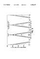
- FIG. 3is a graph showing initial GEOS satellite relay equatorial angle from a MEO satellite relay plane versus minimum tangent altitude above 75 kilometers for valid GEOS satellite relay ranger for an embodiment employing an eight-hour MEO period.
- FIG. 4is a graph showing initial GEOS satellite relay equatorial angle from a MEO satellite relay plane versus minimum tangent altitude above 75 kilometers for valid GEOS satellite relay ranges for an embodiment employing a twelve-hour MEO period.
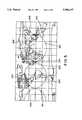
- FIG. 5is a Cartesian world map showing the path that a ten MEO satellite relay embodiment traces upon the earth.
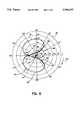
- FIG. 6is a polar plot showing the line-of-sight between a ten MEO satellite relay embodiment and a GEOS satellite relay as viewed from the ten MEO satellite relay embodiment.
- FIG. 7is a polar plot showing the line-of-sight between a ten MEO satellite relay embodiment and a GEOS satellite relay as viewed from the GEOS satellite.
- FIG. 8is a graph showing the coverage that can be achieved with a ten MEO satellite relay embodiment according to the present invention over given latitude and longitude locations.
- FIG. 9is a graph showing initial GEOS satellite relay equatorial angle from a MEO satellite relay plane versus minimum tangent altitude above 75 kilometers for valid GEOS satellite relay ranges of an eight-hour MEO period for an above-the-horizon embodiment according to the present invention.
- FIG. 10is a graph showing initial GEOS satellite relay equatorial angle from a MEO satellite relay plane versus minimum tangent altitude above 75 kilometers for valid GEOS ranges of a twelve-hour MEO period for an above-the-horizon embodiment according to the present invention.
- FIG. 1a first embodiment of a multiple altitude satellite system according to the present invention is shown. More specifically, FIG. 1 shows a configuration of one GEOS satellite relay (geos1 106)and two MEO satellite relays (meo1 108, and meo2 110). The geos1 106 is continuously in line-of-sight contact with meo1 108 and meo2 110.
- a user 120 who cannot communicate directly with a remote earth-based station 122can communicate with meol 108, which in turn is linked continuously with geos1 106 satellite relay. Since geos1 106 is in continuous contact with the earth-based station 122, geos1 106 can forward the communication from meo1 108 to the earth-based station 122.
- One synchronization parameter of the MEO and GEOS satellite relaysis the ratio of their periods.
- a continuous line-of-sight between a MEO satellite relay and a GEOS satellite relayis achievable for several ratios that represent integer factors of twenty-four.
- the period ratio between the GEOS satellite relay's period and the MEO satellite relay's periodis 24:8 or equivalently 3:1.
- a 3:1 period ratiois achieved when the period of the GEOS satellite relay is three times the period of a MEO satellite relay.
- a GEOS satellite relay period of twenty-four hours and a MEO satellite relay period of eight hourswill produce a 3:1 period ratio.
- the GEOS satellite relays in the present inventionrefer to geosynchronous satellites in general and not only to geostationary satellites. The distinction between the two is that a geostationary earth orbit is a geosynchronous orbit with a zero degree inclination-that is, an equatorial-only orbit.
- a geostationary earth orbitis a specific type of geosynchronous orbit.
- polar orbitsare used as examples for the MEO satellites
- equatorial GEOS orbitis used as an example for the GEOS satellites.
- Neither the MEO satellite relays nor the GEOS satellite relaysare limited to these inclinations.
- GEOS and MEO satellite relaysare possible, including varying the number of GEOS and MEO satellite relays, the number of orbit planes of GEOS and MEO satellite relays, the inter-orbit and intra-orbit phasings of the MEO satellite relays, and the inter-orbit and intra-orbit phasings of the GEOS satellite relays.
- the GEOS satellite relaycould be in a polar orbit, or at an orbital altitude which is non-synchronous to the earth.
- the present inventioncan be practiced with the MEO or GEOS satellite relay orbits being circular or elliptical.
- each of the GEOS satellite relayscan continuously view all of the MEO satellite relays.
- MEO satellite relay constellations of 3, 6, 9, or 12 MEO satellite relays with three GEOS satellite relays being 120 degrees apartare examples of this aspect of the present invention.
- each GEOS satellite relaycan provide complete backup of the other GEOS satellite relays.
- FIG. 1shows the use of two orbits for the meo1 and meo2 satellites, it should be understood that both of these satellites could be in a single orbit.
- the present inventionis not dependent upon the number of MEO orbits, as the number of orbits may be modified (such as 1, 2, 3, 4, and so forth).
- the various configurationscan achieve a continuous line-of-sight when: (1) the period ratio is synchronized; and (2) the distance of the line-of-sight from the earth is synchronized with the position of the GEOS satellite relay and the inclination angle of the MEO satellite relay.
- a more detailed discussion of the synchronization involving the distance of the line-of-sight from the earthbegins at FIG. 2.
- FIG. 2shows a polar MEO orbit plane 160 and an equatorial GEOS orbit 162.
- the initial position 164 of the MEO satellite relay 166is assumed to start at the equator and ascend North.
- the initial position 168 of the GEOS satellite relay 170is assumed to start at an angle "Mo" 172 from the polar MEO orbit plane 160.
- LOS 174the line-of-sight
- the LOS 174is not obstructed by the earth 176.
- the altitude of the LOS 174 above the earth 176is called the tangent altitude 178. If the tangent altitude 178 becomes negative, the LOS 174 would be broken.
- the minimum tangent altitude over one GEOS satellite relay orbitis determined for an LOS 174 since that number will indicate how close a satellite relay system is to losing its LOS 174.
- the minimum tangent altitudeis large, then the relative positions of the MEO satellite relay and GEOS satellite relay can be varied greatly before the tangent altitude 178 was reduced to zero and the LOS 174 lost.
- FIG. 3shows the relationship between the initial GEOS equatorial angle from MEO plane ("Mo") and the minimum tangent altitude of the LOS of an eight-hour MEO circular orbit. These relationships are shown for a range of MEO inclinations.
- the orbit configuration of FIG. 2corresponds to the teepee-shaped curves labeled "90" degrees inclination. Any point under the teepee-shaped 90 degree curves represents an initial GEOS/MEO satellite relay relationship that results in an uninterrupted LOS.
- the GEOS satellite relay's initial angle (Mo)could be within the three ranges of 330-30, 90-150, and 210-270 degrees, and would still maintain a continuous LOS.
- MEO satellite relay orbitis inclined at 70 degrees, and are smaller at MEO satellite relay inclinations of 50, 40, or 28 degrees.
- the minimum inclination of 28 degreesis significant in that it allows a wide range of MEO satellite relay orbits at inclinations from less than 28 to 90 degrees.
- the large range of possible configurationsindicates that similar continuous LOS results would be obtained for certain classes of elliptical orbits.
- FIG. 4shows similar data for a twelve-hour MEO satellite relay orbit.
- the inclinations that provide the largest minimum LOS valuesare at 50 and 70 degrees. This indicates that the largest value lies within that range.
- the twelve-hour MEO satellite relay orbithas four "teepees", each in approximately 40 degree range.
- FIG. 3 and FIG. 4can be used to determine a MEO satellite relay position and GEOS satellite relay position that will result in continuous LOS for an eight-hour and twelve-hour MEO satellite relay orbit respectively.
- the references to an eight-hour or twelve-hour orbitdo not indicate that the period of the orbit is exactly eight or twelve hours.
- the referenced periodis the period that is closest to the eight or twelve hours that provides a retrace orbit.
- the ground trace(which is the trace of the point directly below the satellite) exactly retraces the same path on the earth every twenty-four hours which concept is illustrated in FIG. 5.
- FIG. 5shows a configuration of ten MEO satellite relays at positions 201 through 210 respectively.
- FIG. 5shows the ten MEO satellite relays tracing a path on the surface of the earth over a twenty-four hour period.
- the ten MEO satellite relays in the FIG.have the following configuration: 10 orbit planes; 8 hour period; an altitude of 7501 nautical miles; a 252 degree inter-orbit phasing; 36 degree node spacing; and an inclination angle of 50 degrees.
- FIG. 6uses the same satellite relay configuration to show the LOS path 320 from the view of each of the ten MEO satellite relays relative to the GEOS satellite relay at a given point in time.
- the graphitself is a polar plot.
- the counter-clockwise circumferential valueis the value of the yaw 220 of the LOS, with the yaw being the degree of rotation about a satellite's vertical axis.
- the yaw value for each of the MEO satellite relayscan be viewed as a pivoting of the LOS about a vertical line.
- the radial measure of the plotindicates the extent to which the LOS is pointing up or down relative to the center of the earth. For example, if a point were placed on the outer edge 222 of the plot, it would indicate that the MEO satellite relay is "looking" straight up at the GEOS satellite relay and 180 degrees away from the center of the earth. If the point were at the center 224, the satellite is looking straight down towards the center of the earth. Hence, the center 224 of the graph represents the nadir position of a satellite.
- FIG. 6depicts that the LOS from each MEO satellite relay to the GEOS satellite relay varies throughout a twenty-four period.
- the time marks on the graphare at twelve minute intervals.
- Positions 301 to 310indicate the respective start point of each of the ten MEO satellite relays. Although the ten MEO satellite relays start at a different point, they follow the same path over a twenty-four hour period. The ten MEC satellite relays will repeat this LOS path 320 every twenty-four hours.
- the skewed "figure eight" shape of the LOS path 320shows that for this configuration a MEO satellite relay does not look straight down at the center of the earth. In contrast, if a MEO satellite relay did look straight down at the center of the earth, it would have to look through the earth to see the GEOS satellite relay. Thus, the LOS would be broken and the satellite relay configuration would not result in a continuous LOS. Instead, the LOS angle from nadir is large enough to "lift" the LOS higher than the surface of the earth, with the earth limb being at a nadir angle of about 18 degrees .
- FIG. 7likewise uses the same satellite relay configuration to show the LOS path 380 from the view of the GEOS satellite relay relative to each of the ten MEO satellite relays at a given point in time.
- the angular excursionsare not nearly as large.
- the time marks on the graphare at twelve minute intervals.
- Positions 401 to 410indicate the respective start point of each of the ten MEO satellite relays.
- the LOS path 380 shownis for a twenty-four hour period and will repeat every twenty-four hours.
- FIG. 8graphically illustrates the earth coverage from the same ten MEO satellite relay configuration as described in FIG. 7 (that is, 10 orbital planes; 8 hour period; an altitude of 7501 nautical miles; a 252 degree inter-orbit phasing; 36 degree node spacing; and an inclination angle of 50 degrees).
- Each bar on the graphshows the extent of 24 hour coverage at a location for a specific latitude. Since all of the bars are solid, there is a continuous LOS for each location to a MEO satellite relay.
- the ten MEO satellite relayscan "see" the earth's surface continuously with a minimum ground elevation angle of 20 degrees angle of LOS above the earth's surface. While FIG.
- FIGS. 6 and 7employ one satellite per orbital plane, it should be understood that the number of orbital planes could be reduced by placing more than one satellite in one or more of these orbital planes.
- the present inventionalso features another satellite relay configuration which has additional advantages. Some configurations, in addition to providing a continuous LOS between a GEOS satellite relay and a MEO satellite relay, also provide above-the-horizon (ATH) viewing for the GEOS-to-MEO satellite relay links.
- ATHabove-the-horizon
- FIG. 7is revisited to illustrate the ATH aspect.
- FIG. 7shows the view of a GEOS satellite relay "looking down" upon a MEO satellite relay over a twenty-four hour period.
- An above-the horizon (ATH) linkdenotes that a MEO satellite relay does not cross in front of the earth 500 at any time during the twenty-four period. Also, a MEO satellite relay does not cross behind the earth 500 relative to the GEOS satellite relay. For 8hour MEO relays, some configurations can be non-ATH. The trace in FIG. 7 would then cross in front of the earth.
- a multiple altitude satellite relay system that is configured for the ATH featureresults in a more restricted set of ranges for the synchronization parameters for the eight-hour MEO satellite relay orbits.
- FIG. 9shows the valid GEOS satellite relay ranges for an eight-hour ATH MEO satellite relay configuration.
- the ATH "teepee" shapesillustrate that the choices for the initial GEOS satellite relay angles relative to a MEO satellite relay system are more limited. For constellations of MEO satellite relays, the smaller range of angles will produce some reduction in MEO satellite relay configuration options, with a possible reduction in ground coverage.
- FIG. 10illustrates that there would be no additional limitations in a twelve-hour ATH MEO satellite relay configuration. Additional limitations do not result since any twelve-hour ATH MEO satellite relay configuration that provides continuous LOS links also provides continuous ATH links. Therefore a configuration whose ratio of GEOS satellite relay period to MEO satellite relay period is 2:1 will have the ATH feature if they fall within the "teepee" ranges as shown on FIG. 10.
- the Walker Delta Patternprovides an even distribution of satellites in the constellation (see the reference).
- the special Walker constellationhas one satellite per orbit planes, with the total number of satellites being greater than three.
- a unit of angular measurement in the Walker constellationsis the "pattern unit" which is used to describe the relative positions of satellites and orbit planes.
- the pattern unitis defined as 360 degrees divided by the number of satellites, e.g., if the constellation contained four satellites, the pattern unit would be 90 degrees.
- Each satellitecan be placed one pattern unit (90 degrees in this example) further along in its orbit than the satellite in the adjacent plane to the west.
- the satellitescould just as well be placed at two or three pattern units, and still produce a Walker orbit.
- one pattern unitis used for successive satellites that are in eighthour retrace orbits, all the satellites produce the same traces on the ground, that is, all the retrace patterns (FIG. 5) on the earth are the same.
- the sub-satellite points for each MEO satelliteare at different points on the same trace. Because of the geometric relationship, each MEO satellite appears to a GEOS satellite to follow exactly the same path.
- the number of satellitescan be increased and the same superimposed retrace pattern will be produced, if the satellites are placed at the correct number of pattern units. Successive satellites in a five-satellite constellation must be placed at 2 pattern units, six satellites require 3 pattern units and so on. Any eight-hour retrace Walter constellation with one satellite per orbit plane will produce superimposed ground traces when the number of pattern units is three less than the number of satellites. If a GEOS satellite is positioned within the boundaries of the teepee chart in FIG. 3, continuous links are provided with all the MEO satellites and the paths of the MEO satellites as observed from the GEOS satellite are the same.
- each orbit planecan be accommodated with pultiple GEOS satellites.
- multiple MEO satellites per orbitcan still be used as long as the satellites are positioned within the confines of the teepees in FIG. 3 or 4.
Landscapes
- Engineering & Computer Science (AREA)
- Remote Sensing (AREA)
- Physics & Mathematics (AREA)
- Astronomy & Astrophysics (AREA)
- Aviation & Aerospace Engineering (AREA)
- General Physics & Mathematics (AREA)
- Computer Networks & Wireless Communication (AREA)
- Signal Processing (AREA)
- Radio Relay Systems (AREA)
Abstract
Description
Claims (36)
Priority Applications (8)
| Application Number | Priority Date | Filing Date | Title |
|---|---|---|---|
| US08/694,466US5906337A (en) | 1995-10-03 | 1995-10-03 | Multiple altitude satellite relay system and method |
| DE69626253TDE69626253T2 (en) | 1995-10-03 | 1996-09-17 | Method and device with relay satellites of different heights |
| EP96114891AEP0767547B1 (en) | 1995-10-03 | 1996-09-17 | Multiple altitude satellite relay system and method |
| TW085111397ATW312064B (en) | 1995-10-03 | 1996-09-18 | |
| CA002185862ACA2185862C (en) | 1995-10-03 | 1996-09-18 | Multiple altitude satellite relay system and method |
| JP08258378AJP3110686B2 (en) | 1995-10-03 | 1996-09-30 | Multi-altitude satellite relay system and method |
| CN96113079ACN1099773C (en) | 1995-10-03 | 1996-10-03 | Multiple altitude satellite relay system and method |
| US08/757,542US5971324A (en) | 1995-10-03 | 1996-11-27 | Multiple altitude satellite relay system and method |
Applications Claiming Priority (1)
| Application Number | Priority Date | Filing Date | Title |
|---|---|---|---|
| US08/694,466US5906337A (en) | 1995-10-03 | 1995-10-03 | Multiple altitude satellite relay system and method |
Related Child Applications (1)
| Application Number | Title | Priority Date | Filing Date |
|---|---|---|---|
| US08/757,542Continuation-In-PartUS5971324A (en) | 1995-10-03 | 1996-11-27 | Multiple altitude satellite relay system and method |
Publications (1)
| Publication Number | Publication Date |
|---|---|
| US5906337Atrue US5906337A (en) | 1999-05-25 |
Family
ID=24788939
Family Applications (1)
| Application Number | Title | Priority Date | Filing Date |
|---|---|---|---|
| US08/694,466Expired - LifetimeUS5906337A (en) | 1995-10-03 | 1995-10-03 | Multiple altitude satellite relay system and method |
Country Status (7)
| Country | Link |
|---|---|
| US (1) | US5906337A (en) |
| EP (1) | EP0767547B1 (en) |
| JP (1) | JP3110686B2 (en) |
| CN (1) | CN1099773C (en) |
| CA (1) | CA2185862C (en) |
| DE (1) | DE69626253T2 (en) |
| TW (1) | TW312064B (en) |
Cited By (23)
| Publication number | Priority date | Publication date | Assignee | Title |
|---|---|---|---|---|
| US6023605A (en)* | 1997-03-19 | 2000-02-08 | Fujitsu Limited | Dual layer satellite communications system and geostationary satellite therefor |
| US6082677A (en)* | 1997-11-14 | 2000-07-04 | National Space Development Agency Of Japan | Satellite orbiting toward west in the equatorial plane and meteorological satellite system using the satellite |
| US6104911A (en)* | 1997-11-14 | 2000-08-15 | Motorola, Inc. | Communication system with satellite diversity and method of operation thereof |
| US6182927B1 (en)* | 1998-09-24 | 2001-02-06 | The Boeing Company | Medium earth orbit augmentation of a global positioning system for global navigation |
| US6208625B1 (en)* | 1997-06-12 | 2001-03-27 | Motorola, Inc. | Method and apparatus for increasing call-handling capacity using a multi-tier satellite network |
| US6266015B1 (en) | 2000-07-19 | 2001-07-24 | Harris Corporation | Phased array antenna having stacked patch antenna element with single millimeter wavelength feed and microstrip quadrature-to-circular polarization circuit |
| US6272317B1 (en) | 1997-06-02 | 2001-08-07 | Hughes Electronics Corporation | Method and system for providing satellite coverage using fixed spot beams and scanned spot beams |
| US6320546B1 (en) | 2000-07-19 | 2001-11-20 | Harris Corporation | Phased array antenna with interconnect member for electrically connnecting orthogonally positioned elements used at millimeter wavelength frequencies |
| US6339707B1 (en)* | 1997-06-02 | 2002-01-15 | Hughes Electronics Corporation | Method and system for providing wideband communications to mobile users in a satellite-based network |
| US6421012B1 (en) | 2000-07-19 | 2002-07-16 | Harris Corporation | Phased array antenna having patch antenna elements with enhanced parasitic antenna element performance at millimeter wavelength radio frequency signals |
| US6535801B1 (en)* | 2000-01-28 | 2003-03-18 | General Dynamics Decision Systems, Inc. | Method and apparatus for accurately determining the position of satellites in geosynchronous orbits |
| US6570533B2 (en) | 2000-05-30 | 2003-05-27 | Nokia Mobile Phones Ltd. | Method for determining the phase of information, and an electronic device |
| US6708029B2 (en) | 1997-06-02 | 2004-03-16 | Hughes Electronics Corporation | Broadband communication system for mobile users in a satellite-based network |
| US7107007B1 (en)* | 2005-10-14 | 2006-09-12 | Korea Aerospace Research Institute | Positioning system for a geostationary satellite |
| US20070037514A1 (en)* | 2005-08-09 | 2007-02-15 | Atc Technologies, Llc | Satellite communications systems and methods using substantially co-located feeder link antennas |
| US7255308B1 (en) | 2004-03-23 | 2007-08-14 | Northrop Grumman Corporation | Solar dominated satellite constellations capable of having repeating common ground tracks |
| US7258305B1 (en) | 2004-03-23 | 2007-08-21 | Northrop Grumman Corporation | Space based change detection using common ground track constellations capable of being configured for multi-manifest launches |
| US7270299B1 (en) | 2004-03-23 | 2007-09-18 | Northrop Grumman Corporation | Space based change detection using common ground track constellations |
| US20080081556A1 (en)* | 2006-10-03 | 2008-04-03 | Raytheon Company | System and method for observing a satellite using a satellite in retrograde orbit |
| US7370566B2 (en)* | 2003-09-04 | 2008-05-13 | Harris Corporation | Complimentary retrograde/prograde satellite constellation |
| US10361773B2 (en)* | 2017-04-24 | 2019-07-23 | Blue Digs LLC | Satellite constellation having multiple orbital inclinations |
| US20220094431A1 (en)* | 2020-09-24 | 2022-03-24 | Hooshang Kaen | Secure global satellite network |
| US11414218B1 (en)* | 2020-06-03 | 2022-08-16 | Amazon Technologies, Inc. | System for maintaining satellites in orbital configuration |
Families Citing this family (17)
| Publication number | Priority date | Publication date | Assignee | Title |
|---|---|---|---|---|
| IL121764A0 (en)* | 1996-11-25 | 1998-02-22 | Motorola Inc | Space-based communication systems |
| US6047161A (en)* | 1996-11-29 | 2000-04-04 | Motorola, Inc. | Satellite communication system and method thereof |
| US6078810A (en)* | 1997-06-12 | 2000-06-20 | Motorola, Inc. | Multiple-tier satelite communication system and method of operation thereof |
| EP0961420A1 (en)* | 1998-05-25 | 1999-12-01 | Hughes Electronics Corporation | Integrated geosynchronous orbit (GSO)/nongeosynchronous orbit (NGSO) Satellite communications system |
| US6859652B2 (en) | 2000-08-02 | 2005-02-22 | Mobile Satellite Ventures, Lp | Integrated or autonomous system and method of satellite-terrestrial frequency reuse using signal attenuation and/or blockage, dynamic assignment of frequencies and/or hysteresis |
| EP1316233B1 (en) | 2000-08-02 | 2011-10-05 | ATC Technologies, LLC | Coordinated frequency reuse of a terrestrial and a satellite system. |
| US7792488B2 (en) | 2000-12-04 | 2010-09-07 | Atc Technologies, Llc | Systems and methods for transmitting electromagnetic energy over a wireless channel having sufficiently weak measured signal strength |
| JP2014172555A (en)* | 2013-03-12 | 2014-09-22 | Mitsubishi Electric Corp | Satellite observation system |
| US9991950B2 (en)* | 2015-07-24 | 2018-06-05 | Worldvu Satellites Limited | Communication-satellite system with enhanced capacity in designated locations |
| CA2927217A1 (en)* | 2016-04-14 | 2017-10-14 | Telesat Canada | Dual leo satellite system and method for global coverage |
| US10053241B2 (en)* | 2016-12-01 | 2018-08-21 | The Boeing Company | Systems and methods for multi-spacecraft distributed ascent |
| DE102017111091B4 (en)* | 2017-05-22 | 2019-01-10 | Deutsches Zentrum für Luft- und Raumfahrt e.V. | Satellite system for navigation and / or geodesy |
| WO2020157807A1 (en)* | 2019-01-28 | 2020-08-06 | 三菱電機株式会社 | Satellite constellation formation system, satellite constellation formation method, debris removal scheme, satellite constellation construction scheme, and ground equipment |
| CN111600648B (en)* | 2020-05-25 | 2022-02-22 | 中国矿业大学 | Mobile relay position control method of mobile edge computing system |
| JP7455018B2 (en)* | 2020-07-27 | 2024-03-25 | 三菱電機株式会社 | Space object management system, ground equipment, space object management device and monitoring satellite |
| US20240025564A1 (en)* | 2020-09-28 | 2024-01-25 | Mitsubishi Electric Corporation | Monitoring system, monitoring satellite, and communication satellite |
| WO2023022735A1 (en)* | 2021-08-20 | 2023-02-23 | Viasat, Inc. | Lower orbit satellite tracking |
Citations (36)
| Publication number | Priority date | Publication date | Assignee | Title |
|---|---|---|---|---|
| US3163820A (en)* | 1961-05-22 | 1964-12-29 | Bell Telephone Labor Inc | Satellite communication system employing a retrograding orbit |
| US3452356A (en)* | 1966-06-07 | 1969-06-24 | North American Rockwell | Directional radio relay system |
| US3471856A (en)* | 1967-05-22 | 1969-10-07 | Nasa | Position location and data collection system and method |
| US3540048A (en)* | 1966-10-19 | 1970-11-10 | Nasa | Deep space-monitor communication satellite system |
| US3742498A (en)* | 1970-05-06 | 1973-06-26 | Itt | Synchronization and position location system |
| US3993997A (en)* | 1969-03-28 | 1976-11-23 | Navsat Corporation | Communication system and method |
| US4004098A (en)* | 1973-12-06 | 1977-01-18 | Communications Satellite Corporation (Comsat) | Satellite on-board switching system with satellite-to-satellite link |
| EP0059454A2 (en)* | 1981-02-28 | 1982-09-08 | Siemens Aktiengesellschaft | Communication satellite system in geostationary loop positions |
| US4375697A (en)* | 1980-09-04 | 1983-03-01 | Hughes Aircraft Company | Satellite arrangement providing effective use of the geostationary orbit |
| DE3421855A1 (en)* | 1984-06-13 | 1985-12-19 | Otto Karl Dipl.-Ing. 6057 Dietzenbach Poisel | Defo-system |
| US4652884A (en)* | 1984-07-20 | 1987-03-24 | Deutsche Forschungs-Und Versuchsanstalt Fur Luft-Und Raumfahrt E.V. | Satellite navigational system and method |
| DE3605096A1 (en)* | 1986-02-18 | 1987-08-20 | Erno Raumfahrttechnik Gmbh | COMBINED SATELLITE DEVICE FOR GLOBAL TELECOMMUNICATION AND / OR POSITION DETERMINATION |
| US4726224A (en)* | 1986-02-24 | 1988-02-23 | Ausilio Robert F D | System for testing space weapons |
| WO1988004866A1 (en)* | 1986-12-23 | 1988-06-30 | Messerschmitt-Bölkow-Blohm Gesellschaft Mit Beschr | Process for data transmission by means of a geo-stationary satellite and at least one sub-satellite |
| US4819053A (en)* | 1986-05-09 | 1989-04-04 | Halavais Richard A | Single-point locating system |
| US4843397A (en)* | 1987-03-26 | 1989-06-27 | Selenia Spazio Spa | Distributed-array radar system comprising an array of interconnected elementary satellites |
| JPH02128996A (en)* | 1988-11-10 | 1990-05-17 | Nec Corp | Satellite orbit arrangement method |
| US5041833A (en)* | 1988-03-28 | 1991-08-20 | Stanford Telecommunications, Inc. | Precise satellite ranging and timing system using pseudo-noise bandwidth synthesis |
| US5046006A (en)* | 1989-02-28 | 1991-09-03 | Raoul D. Revord | Mutual missile control system |
| JPH03270422A (en)* | 1990-03-20 | 1991-12-02 | Nec Corp | Mobile object satellite communicating/position measuring system |
| JPH0472000A (en)* | 1990-07-10 | 1992-03-06 | Takeshi Hatsuda | Geostationary optical fiber tether satellite system |
| JPH0479429A (en)* | 1990-07-18 | 1992-03-12 | Nec Corp | Artificial satellite communication system |
| US5099235A (en)* | 1990-05-14 | 1992-03-24 | Hughes Aircraft Company | Method for transferring data through a network of intelligent control stations using decentralized control techniques |
| JPH0496528A (en)* | 1990-08-13 | 1992-03-27 | Nec Corp | Radio relay air base |
| US5119225A (en)* | 1988-01-18 | 1992-06-02 | British Aerospace Public Limited Company | Multiple access communication system |
| US5199672A (en)* | 1990-05-25 | 1993-04-06 | Orbital Sciences Corporation | Method and apparatus for deploying a satellite network |
| US5218467A (en)* | 1990-12-28 | 1993-06-08 | Nasa And Laser Data Technology, Inc. | Multi-access laser communications transceiver system |
| US5394561A (en)* | 1990-03-06 | 1995-02-28 | Motorola, Inc. | Networked satellite and terrestrial cellular radiotelephone systems |
| US5396643A (en)* | 1992-08-24 | 1995-03-07 | Motorola, Inc. | Geographic-area selective low-earth satellite-based paging broadcast system and method |
| US5412660A (en)* | 1993-09-10 | 1995-05-02 | Trimble Navigation Limited | ISDN-to-ISDN communication via satellite microwave radio frequency communications link |
| US5414432A (en)* | 1992-03-04 | 1995-05-09 | Motorola, Inc. | Position locating transceiver |
| US5423084A (en)* | 1992-05-11 | 1995-06-06 | Motorola, Inc. | Spectrum recovery apparatus and method therefor |
| US5430729A (en)* | 1994-04-04 | 1995-07-04 | Motorola, Inc. | Method and apparatus for adaptive directed route randomization and distribution in a richly connected communication network |
| US5433726A (en)* | 1991-04-22 | 1995-07-18 | Trw Inc. | Medium-earth-altitude satellite-based cellular telecommunications system |
| US5717404A (en)* | 1996-05-15 | 1998-02-10 | Hughes Electronics | Satellite ephemeris determination system using GPS tracking techniques |
| US5722042A (en)* | 1995-02-06 | 1998-02-24 | Atr Optical And Radio Communications Research Laboratories | Satellite communication system having double-layered earth orbit satellite constellation with two different altitudes |
Family Cites Families (1)
| Publication number | Priority date | Publication date | Assignee | Title |
|---|---|---|---|---|
| US5363368A (en)* | 1992-05-26 | 1994-11-08 | Motorola, Inc. | Simultaneous TDMA communication system |
- 1995
- 1995-10-03USUS08/694,466patent/US5906337A/ennot_activeExpired - Lifetime
- 1996
- 1996-09-17EPEP96114891Apatent/EP0767547B1/ennot_activeExpired - Lifetime
- 1996-09-17DEDE69626253Tpatent/DE69626253T2/ennot_activeExpired - Lifetime
- 1996-09-18CACA002185862Apatent/CA2185862C/ennot_activeExpired - Fee Related
- 1996-09-18TWTW085111397Apatent/TW312064B/zhactive
- 1996-09-30JPJP08258378Apatent/JP3110686B2/ennot_activeExpired - Fee Related
- 1996-10-03CNCN96113079Apatent/CN1099773C/ennot_activeExpired - Fee Related
Patent Citations (37)
| Publication number | Priority date | Publication date | Assignee | Title |
|---|---|---|---|---|
| US3163820A (en)* | 1961-05-22 | 1964-12-29 | Bell Telephone Labor Inc | Satellite communication system employing a retrograding orbit |
| US3452356A (en)* | 1966-06-07 | 1969-06-24 | North American Rockwell | Directional radio relay system |
| US3540048A (en)* | 1966-10-19 | 1970-11-10 | Nasa | Deep space-monitor communication satellite system |
| US3471856A (en)* | 1967-05-22 | 1969-10-07 | Nasa | Position location and data collection system and method |
| US3993997A (en)* | 1969-03-28 | 1976-11-23 | Navsat Corporation | Communication system and method |
| US3742498A (en)* | 1970-05-06 | 1973-06-26 | Itt | Synchronization and position location system |
| US4004098A (en)* | 1973-12-06 | 1977-01-18 | Communications Satellite Corporation (Comsat) | Satellite on-board switching system with satellite-to-satellite link |
| US4375697A (en)* | 1980-09-04 | 1983-03-01 | Hughes Aircraft Company | Satellite arrangement providing effective use of the geostationary orbit |
| EP0059454A2 (en)* | 1981-02-28 | 1982-09-08 | Siemens Aktiengesellschaft | Communication satellite system in geostationary loop positions |
| US4502051A (en)* | 1981-02-28 | 1985-02-26 | Siemens Aktiengesellschaft | Telecommunication system with satellites positioned in geostationary positional loops |
| DE3421855A1 (en)* | 1984-06-13 | 1985-12-19 | Otto Karl Dipl.-Ing. 6057 Dietzenbach Poisel | Defo-system |
| US4652884A (en)* | 1984-07-20 | 1987-03-24 | Deutsche Forschungs-Und Versuchsanstalt Fur Luft-Und Raumfahrt E.V. | Satellite navigational system and method |
| DE3605096A1 (en)* | 1986-02-18 | 1987-08-20 | Erno Raumfahrttechnik Gmbh | COMBINED SATELLITE DEVICE FOR GLOBAL TELECOMMUNICATION AND / OR POSITION DETERMINATION |
| US4726224A (en)* | 1986-02-24 | 1988-02-23 | Ausilio Robert F D | System for testing space weapons |
| US4819053A (en)* | 1986-05-09 | 1989-04-04 | Halavais Richard A | Single-point locating system |
| WO1988004866A1 (en)* | 1986-12-23 | 1988-06-30 | Messerschmitt-Bölkow-Blohm Gesellschaft Mit Beschr | Process for data transmission by means of a geo-stationary satellite and at least one sub-satellite |
| US4843397A (en)* | 1987-03-26 | 1989-06-27 | Selenia Spazio Spa | Distributed-array radar system comprising an array of interconnected elementary satellites |
| US5119225A (en)* | 1988-01-18 | 1992-06-02 | British Aerospace Public Limited Company | Multiple access communication system |
| US5041833A (en)* | 1988-03-28 | 1991-08-20 | Stanford Telecommunications, Inc. | Precise satellite ranging and timing system using pseudo-noise bandwidth synthesis |
| JPH02128996A (en)* | 1988-11-10 | 1990-05-17 | Nec Corp | Satellite orbit arrangement method |
| US5046006A (en)* | 1989-02-28 | 1991-09-03 | Raoul D. Revord | Mutual missile control system |
| US5394561A (en)* | 1990-03-06 | 1995-02-28 | Motorola, Inc. | Networked satellite and terrestrial cellular radiotelephone systems |
| JPH03270422A (en)* | 1990-03-20 | 1991-12-02 | Nec Corp | Mobile object satellite communicating/position measuring system |
| US5099235A (en)* | 1990-05-14 | 1992-03-24 | Hughes Aircraft Company | Method for transferring data through a network of intelligent control stations using decentralized control techniques |
| US5199672A (en)* | 1990-05-25 | 1993-04-06 | Orbital Sciences Corporation | Method and apparatus for deploying a satellite network |
| JPH0472000A (en)* | 1990-07-10 | 1992-03-06 | Takeshi Hatsuda | Geostationary optical fiber tether satellite system |
| JPH0479429A (en)* | 1990-07-18 | 1992-03-12 | Nec Corp | Artificial satellite communication system |
| JPH0496528A (en)* | 1990-08-13 | 1992-03-27 | Nec Corp | Radio relay air base |
| US5218467A (en)* | 1990-12-28 | 1993-06-08 | Nasa And Laser Data Technology, Inc. | Multi-access laser communications transceiver system |
| US5433726A (en)* | 1991-04-22 | 1995-07-18 | Trw Inc. | Medium-earth-altitude satellite-based cellular telecommunications system |
| US5414432A (en)* | 1992-03-04 | 1995-05-09 | Motorola, Inc. | Position locating transceiver |
| US5423084A (en)* | 1992-05-11 | 1995-06-06 | Motorola, Inc. | Spectrum recovery apparatus and method therefor |
| US5396643A (en)* | 1992-08-24 | 1995-03-07 | Motorola, Inc. | Geographic-area selective low-earth satellite-based paging broadcast system and method |
| US5412660A (en)* | 1993-09-10 | 1995-05-02 | Trimble Navigation Limited | ISDN-to-ISDN communication via satellite microwave radio frequency communications link |
| US5430729A (en)* | 1994-04-04 | 1995-07-04 | Motorola, Inc. | Method and apparatus for adaptive directed route randomization and distribution in a richly connected communication network |
| US5722042A (en)* | 1995-02-06 | 1998-02-24 | Atr Optical And Radio Communications Research Laboratories | Satellite communication system having double-layered earth orbit satellite constellation with two different altitudes |
| US5717404A (en)* | 1996-05-15 | 1998-02-10 | Hughes Electronics | Satellite ephemeris determination system using GPS tracking techniques |
Non-Patent Citations (7)
| Title |
|---|
| A Polar Orbiting Satellite System as an Extension of Inmarsat, J. Nauck, K. Plate and B. Bischof; 35 th Congress of the International Astronautical Federation, Oct. 7 13k, 1984.* |
| A Polar Orbiting Satellite System as an Extension of Inmarsat, J. Nauck, K. Plate and B. Bischof; 35th Congress of the International Astronautical Federation, Oct. 7-13k, 1984. |
| A Search and Rescue Satellite System in Addition to Inmarsat, J.Nauck; 33 rd Congress of the International Astronautical Federation, Sep. 27 Oct. 2, 1982.* |
| A Search and Rescue Satellite System in Addition to Inmarsat, J.Nauck; 33rd Congress of the International Astronautical Federation, Sep. 27-Oct. 2, 1982. |
| A. R. Collar and J. W. Flower, A (Relatively) Low Altitude 24 Hour Satellite May 28, 1969.* |
| A. R. Collar and J. W. Flower, A (Relatively) Low Altitude 24-Hour Satellite May 28, 1969. |
| R. A. Stampfl, Relay Satellite Systems (TDRS).* |
Cited By (35)
| Publication number | Priority date | Publication date | Assignee | Title |
|---|---|---|---|---|
| US6023605A (en)* | 1997-03-19 | 2000-02-08 | Fujitsu Limited | Dual layer satellite communications system and geostationary satellite therefor |
| US6339707B1 (en)* | 1997-06-02 | 2002-01-15 | Hughes Electronics Corporation | Method and system for providing wideband communications to mobile users in a satellite-based network |
| US6272317B1 (en) | 1997-06-02 | 2001-08-07 | Hughes Electronics Corporation | Method and system for providing satellite coverage using fixed spot beams and scanned spot beams |
| US20040157554A1 (en)* | 1997-06-02 | 2004-08-12 | Hughes Electronics Corporation | Broadband communication system for mobile users in a satellite-based network |
| US6336030B2 (en) | 1997-06-02 | 2002-01-01 | Hughes Electronics Corporation | Method and system for providing satellite coverage using fixed spot beams and scanned spot beams |
| US6708029B2 (en) | 1997-06-02 | 2004-03-16 | Hughes Electronics Corporation | Broadband communication system for mobile users in a satellite-based network |
| US7324056B2 (en) | 1997-06-02 | 2008-01-29 | The Directv Group, Inc. | Broadband communication system for mobile users in a satellite-based network |
| US6208625B1 (en)* | 1997-06-12 | 2001-03-27 | Motorola, Inc. | Method and apparatus for increasing call-handling capacity using a multi-tier satellite network |
| US6104911A (en)* | 1997-11-14 | 2000-08-15 | Motorola, Inc. | Communication system with satellite diversity and method of operation thereof |
| US6082677A (en)* | 1997-11-14 | 2000-07-04 | National Space Development Agency Of Japan | Satellite orbiting toward west in the equatorial plane and meteorological satellite system using the satellite |
| US6182927B1 (en)* | 1998-09-24 | 2001-02-06 | The Boeing Company | Medium earth orbit augmentation of a global positioning system for global navigation |
| US6535801B1 (en)* | 2000-01-28 | 2003-03-18 | General Dynamics Decision Systems, Inc. | Method and apparatus for accurately determining the position of satellites in geosynchronous orbits |
| US6570533B2 (en) | 2000-05-30 | 2003-05-27 | Nokia Mobile Phones Ltd. | Method for determining the phase of information, and an electronic device |
| US6421012B1 (en) | 2000-07-19 | 2002-07-16 | Harris Corporation | Phased array antenna having patch antenna elements with enhanced parasitic antenna element performance at millimeter wavelength radio frequency signals |
| US6320546B1 (en) | 2000-07-19 | 2001-11-20 | Harris Corporation | Phased array antenna with interconnect member for electrically connnecting orthogonally positioned elements used at millimeter wavelength frequencies |
| US6266015B1 (en) | 2000-07-19 | 2001-07-24 | Harris Corporation | Phased array antenna having stacked patch antenna element with single millimeter wavelength feed and microstrip quadrature-to-circular polarization circuit |
| US7370566B2 (en)* | 2003-09-04 | 2008-05-13 | Harris Corporation | Complimentary retrograde/prograde satellite constellation |
| US7255308B1 (en) | 2004-03-23 | 2007-08-14 | Northrop Grumman Corporation | Solar dominated satellite constellations capable of having repeating common ground tracks |
| US7258305B1 (en) | 2004-03-23 | 2007-08-21 | Northrop Grumman Corporation | Space based change detection using common ground track constellations capable of being configured for multi-manifest launches |
| US7270299B1 (en) | 2004-03-23 | 2007-09-18 | Northrop Grumman Corporation | Space based change detection using common ground track constellations |
| US20070037514A1 (en)* | 2005-08-09 | 2007-02-15 | Atc Technologies, Llc | Satellite communications systems and methods using substantially co-located feeder link antennas |
| US7831202B2 (en)* | 2005-08-09 | 2010-11-09 | Atc Technologies, Llc | Satellite communications systems and methods using substantially co-located feeder link antennas |
| US7107007B1 (en)* | 2005-10-14 | 2006-09-12 | Korea Aerospace Research Institute | Positioning system for a geostationary satellite |
| US20080081556A1 (en)* | 2006-10-03 | 2008-04-03 | Raytheon Company | System and method for observing a satellite using a satellite in retrograde orbit |
| US8090312B2 (en)* | 2006-10-03 | 2012-01-03 | Raytheon Company | System and method for observing a satellite using a satellite in retrograde orbit |
| US11063660B2 (en)* | 2017-04-24 | 2021-07-13 | Blue Digs LLC | Satellite constellation having multiple orbital inclinations |
| US10707953B2 (en)* | 2017-04-24 | 2020-07-07 | Blue Digs LLC | Satellite constellation having multiple orbital inclinations |
| US10361773B2 (en)* | 2017-04-24 | 2019-07-23 | Blue Digs LLC | Satellite constellation having multiple orbital inclinations |
| US20220094429A1 (en)* | 2017-04-24 | 2022-03-24 | Blue Digs LLC | Satellite Constellation Having Multiple Orbital Inclinations |
| US11799542B2 (en)* | 2017-04-24 | 2023-10-24 | Blue Digs LLC | Satellite constellation having multiple orbital inclinations |
| US20230421247A1 (en)* | 2017-04-24 | 2023-12-28 | Blue Digs LLC | Satellite Constellation Having Multiple Orbital Inclinations |
| US12199739B2 (en)* | 2017-04-24 | 2025-01-14 | Blue Digs LLC | Satellite constellation having multiple orbital inclinations |
| US11414218B1 (en)* | 2020-06-03 | 2022-08-16 | Amazon Technologies, Inc. | System for maintaining satellites in orbital configuration |
| US20220094431A1 (en)* | 2020-09-24 | 2022-03-24 | Hooshang Kaen | Secure global satellite network |
| US12355547B2 (en)* | 2020-09-24 | 2025-07-08 | Hooshang Kaen | Secure global satellite network |
Also Published As
| Publication number | Publication date |
|---|---|
| EP0767547A3 (en) | 2001-04-04 |
| JPH09130317A (en) | 1997-05-16 |
| DE69626253D1 (en) | 2003-03-27 |
| CN1099773C (en) | 2003-01-22 |
| CA2185862A1 (en) | 1997-04-04 |
| EP0767547B1 (en) | 2003-02-19 |
| JP3110686B2 (en) | 2000-11-20 |
| TW312064B (en) | 1997-08-01 |
| DE69626253T2 (en) | 2003-11-13 |
| EP0767547A2 (en) | 1997-04-09 |
| CN1156357A (en) | 1997-08-06 |
| CA2185862C (en) | 2005-08-23 |
Similar Documents
| Publication | Publication Date | Title |
|---|---|---|
| US5906337A (en) | Multiple altitude satellite relay system and method | |
| US5971324A (en) | Multiple altitude satellite relay system and method | |
| US10512021B2 (en) | System and method for providing continuous communications access to satellites in geocentric, non-geosynchronous orbits | |
| US20210316886A1 (en) | Earth observation satellite information routing system | |
| US6198907B1 (en) | Satellite communications systems using satellites in a zero-drift constellation | |
| US5890679A (en) | Medium earth orbit communication satellite system | |
| EP0648027B1 (en) | Medium-earth-altitude satellite based cellular telecommunications | |
| EP1347916B1 (en) | A system and method for implementing a constellation of non-geostationary satellites that provides simplified satellite tracking | |
| US6785553B2 (en) | Position location of multiple transponding platforms and users using two-way ranging as a calibration reference for GPS | |
| US5822680A (en) | Frequency sharing for satellite communication system | |
| JP2001506465A (en) | High latitude geostationary satellite system | |
| US12355547B2 (en) | Secure global satellite network | |
| US6267329B1 (en) | Medium earth orbit communications satellite system | |
| WO2016145326A1 (en) | Co-orbiting laser communications relay satellite | |
| US20080099625A1 (en) | First satellite sub-constellation and offset second satellite sub-constellation | |
| CN113647030B (en) | Method and system for hybrid communication | |
| JPH10336111A (en) | Method and device for interruption preventing operation of inter satellite communication link in leo network | |
| CN119906474B (en) | Moon-passing remote-guiding satellite formation system and cooperative working method | |
| US20180367216A1 (en) | Communications relay satellite with a single-axis gimbal | |
| Edwards et al. | A geosynchronous orbit optical communications relay architecture | |
| WO2007058721A1 (en) | First satellite sub-constellation and offset second satellite sub-constellation | |
| EP0836290A2 (en) | Satellite communication method using satellites on substantially circular orbit, inclined to the equatorial plane with period matching the earth period | |
| Perea-Tamayo et al. | Design and evaluation of a low-cost cubesat communication relay constellation | |
| US7489927B2 (en) | Method and system for object tracking and communication | |
| Edery-Guirardo | Small relay satellite (s) for improving the reactivity of observation satellites |
Legal Events
| Date | Code | Title | Description |
|---|---|---|---|
| AS | Assignment | Owner name:TRW INC., CALIFORNIA Free format text:ASSIGNMENT OF ASSIGNORS INTEREST;ASSIGNORS:WILLIAMS, BRIAN R.;CROSS, PETER H.;REEL/FRAME:008121/0875 Effective date:19951003 | |
| STCF | Information on status: patent grant | Free format text:PATENTED CASE | |
| FPAY | Fee payment | Year of fee payment:4 | |
| AS | Assignment | Owner name:NORTHROP GRUMMAN CORPORATION, CALIFORNIA Free format text:ASSIGNMENT OF ASSIGNORS INTEREST;ASSIGNOR:TRW, INC. N/K/A NORTHROP GRUMMAN SPACE AND MISSION SYSTEMS CORPORATION, AN OHIO CORPORATION;REEL/FRAME:013751/0849 Effective date:20030122 Owner name:NORTHROP GRUMMAN CORPORATION,CALIFORNIA Free format text:ASSIGNMENT OF ASSIGNORS INTEREST;ASSIGNOR:TRW, INC. N/K/A NORTHROP GRUMMAN SPACE AND MISSION SYSTEMS CORPORATION, AN OHIO CORPORATION;REEL/FRAME:013751/0849 Effective date:20030122 | |
| FPAY | Fee payment | Year of fee payment:8 | |
| FEPP | Fee payment procedure | Free format text:PAYOR NUMBER ASSIGNED (ORIGINAL EVENT CODE: ASPN); ENTITY STATUS OF PATENT OWNER: LARGE ENTITY | |
| AS | Assignment | Owner name:NORTHROP GRUMMAN SPACE & MISSION SYSTEMS CORP.,CAL Free format text:ASSIGNMENT OF ASSIGNORS INTEREST;ASSIGNOR:NORTHROP GRUMMAN CORPORTION;REEL/FRAME:023699/0551 Effective date:20091125 Owner name:NORTHROP GRUMMAN SPACE & MISSION SYSTEMS CORP., CA Free format text:ASSIGNMENT OF ASSIGNORS INTEREST;ASSIGNOR:NORTHROP GRUMMAN CORPORTION;REEL/FRAME:023699/0551 Effective date:20091125 | |
| AS | Assignment | Owner name:NORTHROP GRUMMAN SYSTEMS CORPORATION,CALIFORNIA Free format text:ASSIGNMENT OF ASSIGNORS INTEREST;ASSIGNOR:NORTHROP GRUMMAN SPACE & MISSION SYSTEMS CORP.;REEL/FRAME:023915/0446 Effective date:20091210 Owner name:NORTHROP GRUMMAN SYSTEMS CORPORATION, CALIFORNIA Free format text:ASSIGNMENT OF ASSIGNORS INTEREST;ASSIGNOR:NORTHROP GRUMMAN SPACE & MISSION SYSTEMS CORP.;REEL/FRAME:023915/0446 Effective date:20091210 | |
| FPAY | Fee payment | Year of fee payment:12 |