US5906228A - Gasoline dispensing system and method with radio frequency customer identification antenna - Google Patents
Gasoline dispensing system and method with radio frequency customer identification antennaDownload PDFInfo
- Publication number
- US5906228A US5906228AUS08/936,263US93626397AUS5906228AUS 5906228 AUS5906228 AUS 5906228AUS 93626397 AUS93626397 AUS 93626397AUS 5906228 AUS5906228 AUS 5906228A
- Authority
- US
- United States
- Prior art keywords
- rod
- antenna
- dispenser
- bracket
- force
- Prior art date
- Legal status (The legal status is an assumption and is not a legal conclusion. Google has not performed a legal analysis and makes no representation as to the accuracy of the status listed.)
- Expired - Fee Related
Links
Images


Classifications
- H—ELECTRICITY
- H01—ELECTRIC ELEMENTS
- H01Q—ANTENNAS, i.e. RADIO AERIALS
- H01Q1/00—Details of, or arrangements associated with, antennas
- H01Q1/12—Supports; Mounting means
- H01Q1/22—Supports; Mounting means by structural association with other equipment or articles
- H01Q1/2208—Supports; Mounting means by structural association with other equipment or articles associated with components used in interrogation type services, i.e. in systems for information exchange between an interrogator/reader and a tag/transponder, e.g. in Radio Frequency Identification [RFID] systems
- H01Q1/2216—Supports; Mounting means by structural association with other equipment or articles associated with components used in interrogation type services, i.e. in systems for information exchange between an interrogator/reader and a tag/transponder, e.g. in Radio Frequency Identification [RFID] systems used in interrogator/reader equipment
- B—PERFORMING OPERATIONS; TRANSPORTING
- B67—OPENING, CLOSING OR CLEANING BOTTLES, JARS OR SIMILAR CONTAINERS; LIQUID HANDLING
- B67D—DISPENSING, DELIVERING OR TRANSFERRING LIQUIDS, NOT OTHERWISE PROVIDED FOR
- B67D7/00—Apparatus or devices for transferring liquids from bulk storage containers or reservoirs into vehicles or into portable containers, e.g. for retail sale purposes
- B67D7/06—Details or accessories
- B67D7/064—Drive-off preventing means, e.g. in case of non-payment
- B67D7/065—Drive-off preventing means, e.g. in case of non-payment acting on the vehicle
- B—PERFORMING OPERATIONS; TRANSPORTING
- B67—OPENING, CLOSING OR CLEANING BOTTLES, JARS OR SIMILAR CONTAINERS; LIQUID HANDLING
- B67D—DISPENSING, DELIVERING OR TRANSFERRING LIQUIDS, NOT OTHERWISE PROVIDED FOR
- B67D7/00—Apparatus or devices for transferring liquids from bulk storage containers or reservoirs into vehicles or into portable containers, e.g. for retail sale purposes
- B67D7/06—Details or accessories
- B67D7/08—Arrangements of devices for controlling, indicating, metering or registering quantity or price of liquid transferred
- B67D7/14—Arrangements of devices for controlling, indicating, metering or registering quantity or price of liquid transferred responsive to input of recorded programmed information, e.g. on punched cards
- B67D7/145—Arrangements of devices for controlling, indicating, metering or registering quantity or price of liquid transferred responsive to input of recorded programmed information, e.g. on punched cards by wireless communication means, e.g. RF, transponders or the like
- B—PERFORMING OPERATIONS; TRANSPORTING
- B67—OPENING, CLOSING OR CLEANING BOTTLES, JARS OR SIMILAR CONTAINERS; LIQUID HANDLING
- B67D—DISPENSING, DELIVERING OR TRANSFERRING LIQUIDS, NOT OTHERWISE PROVIDED FOR
- B67D7/00—Apparatus or devices for transferring liquids from bulk storage containers or reservoirs into vehicles or into portable containers, e.g. for retail sale purposes
- B67D7/06—Details or accessories
- B67D7/32—Arrangements of safety or warning devices; Means for preventing unauthorised delivery of liquid
- B67D7/34—Means for preventing unauthorised delivery of liquid
- B67D7/344—Means for preventing unauthorised delivery of liquid by checking a correct coupling or coded information
- B67D7/348—Means for preventing unauthorised delivery of liquid by checking a correct coupling or coded information by interrogating an information transmitter, e.g. a transponder
- H—ELECTRICITY
- H01—ELECTRIC ELEMENTS
- H01Q—ANTENNAS, i.e. RADIO AERIALS
- H01Q1/00—Details of, or arrangements associated with, antennas
- H01Q1/08—Means for collapsing antennas or parts thereof
- H01Q1/084—Pivotable antennas
- H—ELECTRICITY
- H01—ELECTRIC ELEMENTS
- H01Q—ANTENNAS, i.e. RADIO AERIALS
- H01Q7/00—Loop antennas with a substantially uniform current distribution around the loop and having a directional radiation pattern in a plane perpendicular to the plane of the loop
Definitions
- the present inventionrelates to gasoline dispensers and, more particularly, to gasoline dispensers that use an antenna to receive radio frequency identification signals from a customer's vehicle to automatically identify the customer, authorize the sale of products or services to the customer, and to subsequently bill the customer's charge account for the products or services.
- the present inventionis particularly useful in a service station environment where customers may purchase fuel for their vehicles, obtain a car wash, or purchase other items such as food, drinks, or sundries from a convenience store, or drive-through window, that may be located on the premises.
- the customerpurchases fuel at a service station
- the customerpresents payment, in the form of cash or credit/debit card, to the service station attendant either before or after fueling.
- the attendantmust control the activation of the dispenser to allow fueling. If payment is required before fueling may begin, the attendant must activate a switch, typically near the cash register, in order to unlock the dispenser to allow fueling to begin. Once fueling has been completed and the dispenser nozzle has been returned to its seat, the attendant manually resets the dispenser again through activation of a switch at the cash register.
- customer-activated-terminalsare provided, each having a card reader, a display which displays messages to the customer, a key pad for use by the customer to make fueling and payment selections, a printer for printing receipts, and individual price displays corresponding to the individual fuel dispensing nozzles of the dispenser.
- U.S. Pat. No. 5,072,380 issued to Robert E. Randelman et al.takes this payment automation one step further by disclosing an automatic vehicle recognition and customer billing system that may be used in a service station environment.
- the systemautomatically recognizes vehicles and correlates the purchase of products and services with the vehicle.
- the system of the '380 patentincludes an antenna embedded in the ground near a gasoline dispensing pump.
- the antennais connected to a controller located in a housing near the antenna.
- the controllercontrols the output of a radio frequency signal from the antenna and can detect an RF input signal.
- the antennais always energized and, therefore, creates an electromagnetic field at a predetermined radio frequency in the fueling area.
- the system of the '380 patentalso includes an emitter (or card) affixed to a vehicle.
- the cardcomprises an RF coil and integrated circuit component. When the card crosses the electromagnetic field, the electromagnetic field energizes the card. The activated card then emits an encoded electromagnetic pulse signal.
- the controllerreceives the signal and converts it into a data bit stream.
- a computerreceives the data bit stream from the controller and in turn utilizes the data for displaying information on the pump display, for controlling the fuel dispenser, and for billing purposes.
- the antenna which emits the electromagnetic fieldis embedded in the ground near the fuel dispenser.
- the installation of such an antennacan be costly and can create a fire hazard from fueling spills or leaks from the fuel storage tanks typically located under ground near the fuel dispensers.
- the systemdoes not adequately prevent a vehicle card from being activated by more than one antenna at a time and detected by more than one controller at a time, such as may happen where antennas are positioned near each other and therefore interfere with one another.
- the systemdoes not prevent the inadvertent detection of vehicle cards not intended to be used in a fueling transaction.
- Another disadvantage of the '380 patentis in connection with service stations that provide for separate fueling from both sides of a dispenser and/or from several closely-spaced rows of dispensers.
- the vehicle card of a vehicle stopped between antennasmay be detected by the wrong controller, i.e., one not associated with the dispenser where the vehicle is actually receiving fuel, or may wrongly be detected by a controller, i.e., where the vehicle is stopped near an antenna but is not fueling.
- TIRISTMTexas Instruments Registration and Identification Systems
- the TIRISTM product lineincludes radio frequency transponders (read-only as well as read-write) that may be low frequency or high frequency in their operation and which may be attached to or embedded in objects or may be hand-held. Readers, through antennas, send out radio frequency waves to the transponders, and the transponders broadcast stored data back to the reader for processing.
- TIRISTM product lineis a fuel dispensing system (where a transponder is mounted beside the vehicle's fuel tank and a transceiver is mounted on the fuel dispensing nozzle).
- the fuel dispensing system applicationis not desirable because maintenance of the fuel dispensing nozzle with the transceiver can present a service problem as well as a replacement problem and, furthermore, the location of the transponder and transceiver can create a fire hazard.
- Copending U.S patent application Ser. No. 08/768,723is assigned to the assignee of the present invention and solves these problems by providing a radio frequency customer identification system and method which determines whether a transponder containing customer identification data is within range of a gasoline dispenser.
- the dispenseris designed to require activation by the customer to initiate a transaction, and an antenna is associated with each dispensing area of the dispenser and is mounted to the tops of the dispensers. Readers housed in the dispensers send radio frequency power pulses to the antennas which in turn direct the power pulses to create electromagnetic fields.
- the antennasare optimally positioned so that the electromagnetic fields cover predetermined areas near the dispenser.
- the antennasalso pick-up customer identification data that is broadcast by the transponders.
- a vehicle-mounted transponderenters the electromagnetic field created by a long-range antenna, the vehicle-mounted transponder will become activated and broadcast its customer identification (“CID") code.
- the antennadetects the CID code and sends the code to the associated reader for decoding and processing.
- a processoris connected to the reader and to the dispenser for associating customer identification data received at the dispensing area with a transaction at the dispenser, whereupon the transaction at the dispenser is charged to the customer according to the customer identification data.
- the arrangement disclosed in this patent applicationovercomes the above-noted problems with the prior art by providing a reliable, safe, customer-friendly identification system that can automatically identify customer purchasing services or products at a service station, and bill the customer's account for any purchases made.
- the design of the above-described antenna used in the system disclosed in the patent applicationis such that it must project laterally from its respective dispenser, and, as such, is susceptible to being struck by vehicles as they pass by the dispenser. If this occurs, the antenna can be severely and permanently damaged, often requiring shut down of the dispenser while the antenna is replaced.
- the dispensing system and method of the present inventionaccordingly, utilizes a antenna in a radio frequency customer identification system for service stations to reliably and accurately identify and charge customers for their purchases.
- the antenna of the present inventionincludes a bracket adapted to be affixed to the object, a rod pivotally mounted to the bracket, and a spring normally urging the rod to a first position, the rod being pivotal to a second position in response to a force applied to the rod in a direction towards the second position.
- the antenna of the present inventioncan thus survive being struck by a vehicle as it passes by the dispenser and, in fact, can remain operable. This, of course, eliminates the high parts and labor costs associated with a shut-down of the dispenser in the event that the antenna is permanently damaged.
- FIG. 1is an isometric view of a gasoline dispenser having two antennas of the present invention mounted thereto.
- FIG. 2is an enlarged isometric view of one of the antennas of FIG. 1.
- FIG. 3is a sectional view taken along the line 3--3 of FIG. 2.
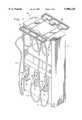
- FIGS. 4A and 4Bare enlarged views of a portion of a mounting bracket for mounting an antenna of FIG. 1 and 2 to the dispenser of FIG. 1, with the bracket and the antenna being rotated 180 degrees from FIG. 2.
- the reference numeral 10refers, in general, to a gasoline dispenser, including a housing 12 for receiving stored gasoline from an underground storage tank (not shown) and for selectively dispensing the gasoline to vehicles.
- a gasoline dispenserincluding a housing 12 for receiving stored gasoline from an underground storage tank (not shown) and for selectively dispensing the gasoline to vehicles.
- Each side of the housing 12forms a dispensing station with a station on one side of the housing being shown in FIG. 1.
- Three hose assemblies 14a-14care provided at each station which, in turn, have dispensing nozzles 16a-16c, respectively, affixed to one end thereof.
- one or more pumps and flow metersare provided for pumping, and metering the flow of, the gasoline as it flows from the storage tank, through the dispenser 12, and to the nozzles 16a-16c for dispensing into the fuel tanks of vehicles being serviced.
- three conduitswould be provided in the interior of the housing 12 for connecting the underground tank to the hose assemblies 14a-14c.
- each hose assembly 14a-14cincludes two hoses connected to their respective dispensing nozzles 16a-16c for respectively dispensing the gasoline through one of the hoses and for receiving the displaced vapor/air mixture from the vehicle tank in the other hose, as will be described.
- the housing 12is provided with three boots, or receptacles, 12a-12c for receiving the nozzles 16a-16c during non-use and, although not shown, it is understood that conventional switches, displays, and the like are also provided on the housing. It is also understood that the station provided on the other side of the housing 12 is identical to the station just described and that, in a normal installation, several dispensers, identical to the dispenser 10, would be provided.
- the antenna 20 and 22are mounted to the top of the housing 12 in a manner to be described, and project laterally from the respective sides of the housing.
- the antenna 20is shown in detail in FIG. 2, it being understood that the antenna 22 is constructed and functions in the same manner.
- the antenna 20is formed by a rod 24 formed into a rectangular, closed configuration having two spaced cross-members 24a and 24b for stiffening purposes.
- the antenna 20is preferably formed by an injection molded plastic material with a plurality of loop wires embedded therein in a conventional manner.
- Two spaced mounting flanges 26 and 28extend from one side of the antenna 20 and preferably are formed integrally with the rod 24.
- a housing 29is also formed integrally with the rod 24 and extends between the mounting flanges 26 and 28.
- the housing 29contains a ferrite tuning board and/or rod (not shown) for tuning the antenna in a conventional manner.
- a terminal 29ais affixed to a side wall of the housing 29 receiving an antenna cable (not shown).
- Two mounting brackets 30 and 32are fastened to the top of the dispenser housing 12 near one side wall thereof, and are adapted to receive the mounting flanges 26 and 28, respectively. Since the mounting flanges 26 and 28 are identical, and since the mounting brackets 30 and 32 are identical, only the flange 26 and bracket 30 will be described in detail.
- the bracket 30projects outwardly from the corresponding side wall of the housing 12 and is formed by a flat plate 30a fastened to the upper surface of the dispenser housing 12 in any known manner.
- Two side walls 30b and 30cextend upwardly from the respective longitudinal edges of the plate 30a.
- a shaft, or bolt, 34extends through aligned openings in the side walls 30a and 30b and through a bore formed in the flange 26 to pivotally mount the flange to the bracket.
- the diameters of the latter openingsare larger than the diameter of the shaft 34 so that the flange can both pivot about the shaft 34 and move in an axial direction along the shaft.
- a portion of the projecting portion of the plate 30ais cut out so as to receive the flange 26 when it pivots, as will be described in detail.
- a portion of the flange 26is cut out to form an area 26a for receiving a leaf spring 38.
- An end portion 38a of the spring 38engages the bottom of the plate 30a of the bracket 30, and the other end portion of the spring engages the lower end portion of the flange 26.
- An intermediate portion of the spring 38is wrapped around the shaft 34 to apply a spring tension to the flange 26 to urge it to the horizontal position shown in FIGS. 1-3.
- the design of the spring 38is such that it will permit pivotal movement of the flange 26 in response to a force acting against the rod 24 in a vertical direction as shown by the arrow in FIG. 3, and will return the flange to its normal horizontal position shown in FIG. 3 when the force is released.
- two spaced, beveled ramps 30d and 30eare formed at the end of the bracket 30 and are tapered downwardly from the side walls 30b and 30c respectively. Therefore, if the rod 24 is subjected to a lateral force in a horizontal plane in the direction shown by the arrow in FIG. 4A for example, the flange 26 would move in the same direction along the shaft 24 until it engages the ramp 30d. Further movement of the flange 26 in this direction causes the flange to ride up the ramp 30d thus imparting a vertical component to the flange's movement, as shown in FIG. 4B. This causes the flange 26 to pivot about the shaft 34 towards a vertical position as discussed above. Of course, the flange 26 can also move in a direction opposite that of the arrow in FIG. 4B in which case it would ride up the ramp 30e with the same result.
- the flange 28 (FIG. 2) and the bracket 32are identical to, and function in the same manner as, the flange 26 and the bracket 30 and therefore will not be described in detail.
- the antenna 20 (FIG. 1)is identical to, and functions in the same manner as, the antenna 20 and therefore also will not be described in detail.
- At least one reader(not shown) is housed in the dispenser 12 and sends radio frequency power pulses to the antennas 20 and 22, respectively, which, in turn, direct the power pulses to create electromagnetic fields which cover predetermined areas near the housing 12.
- the antennas 20 and 22also pick-up customer identification data that is broadcast by transponders attached to a vehicle being serviced or carried by the customer. If a vehicle-mounted transponder enters the electromagnetic field created by either antenna 20 or 22, the transponder will become activated and broadcast its customer identification (“CID”) code.
- the antennadetects the CID code and sends the code to the associated reader for decoding and processing as also described above.
- a processoris connected to the reader and to the dispenser for associating customer identification data received at the dispensing area with a transaction at the dispenser, whereupon the transaction at the dispenser is charged to the customer according to the customer identification data. Since these functions of the reader, the transponder and the processor, as well a description of the associated software, are described in detail in the above identified patent application they will not be described any further herein.
- the antenna 20is urged to its normal, horizontal position, as viewed in FIG. 2, by the spring 38 and by the spring (not shown) associated with the flange 28 and the bracket 32, which position is the optimum position for transmitting and receiving the signals in accordance with the foregoing.
- the antenna 20is subjected to a force having a vertical component shown by the arrow in FIG. 3, or a horizontal component in the direction shown by the arrow in FIG. 4a (or in a direction opposite to the latter arrow), the antenna will pivot upwardly to a substantially vertical position thus avoiding any damage to it.
- the antenna 20will be urged back to its horizontal position by the spring 38 and by the spring (not shown) associated with the flange 28 and the bracket 32.
- the antenna of the present inventioncan thus survive being struck by a vehicle as it passes by the dispenser and, in fact, can remain operable. Thus the high parts and labor costs associated with a shut-down of the dispenser in the event that the antenna is permanently damaged are avoided.
- the antenna 20 of the present inventioncan be mounted relative to a portion of the dispenser housing 12 other than the upper surface.
- the present inventionis not limited to the antenna 20 being normally in a horizontal position and pivotal to a vertical position. Rather, the antenna can normally be urged to a position in a first plane and pivotal to a plane extending at an angle to the first plane.
- the antennais not limited to use with a gasoline dispensing system, but can be placed in other environments within the scope of the invention.
Landscapes
- Engineering & Computer Science (AREA)
- Mechanical Engineering (AREA)
- Computer Networks & Wireless Communication (AREA)
- Physics & Mathematics (AREA)
- Mathematical Physics (AREA)
- Theoretical Computer Science (AREA)
- Loading And Unloading Of Fuel Tanks Or Ships (AREA)
Abstract
Description
Claims (13)
Priority Applications (2)
| Application Number | Priority Date | Filing Date | Title |
|---|---|---|---|
| US08/936,263US5906228A (en) | 1997-09-24 | 1997-09-24 | Gasoline dispensing system and method with radio frequency customer identification antenna |
| PCT/US1998/019996WO1999015408A1 (en) | 1997-09-24 | 1998-09-24 | Gasoline dispensing system with an identification antenna |
Applications Claiming Priority (1)
| Application Number | Priority Date | Filing Date | Title |
|---|---|---|---|
| US08/936,263US5906228A (en) | 1997-09-24 | 1997-09-24 | Gasoline dispensing system and method with radio frequency customer identification antenna |
Publications (1)
| Publication Number | Publication Date |
|---|---|
| US5906228Atrue US5906228A (en) | 1999-05-25 |
Family
ID=25468390
Family Applications (1)
| Application Number | Title | Priority Date | Filing Date |
|---|---|---|---|
| US08/936,263Expired - Fee RelatedUS5906228A (en) | 1997-09-24 | 1997-09-24 | Gasoline dispensing system and method with radio frequency customer identification antenna |
Country Status (2)
| Country | Link |
|---|---|
| US (1) | US5906228A (en) |
| WO (1) | WO1999015408A1 (en) |
Cited By (29)
| Publication number | Priority date | Publication date | Assignee | Title |
|---|---|---|---|---|
| US6024142A (en)* | 1998-06-25 | 2000-02-15 | Micron Communications, Inc. | Communications system and method, fleet management system and method, and method of impeding theft of fuel |
| US6116298A (en)* | 1996-10-28 | 2000-09-12 | Hi-G-Tek Ltd. | Fueling system |
| US6184846B1 (en) | 2000-02-03 | 2001-02-06 | Marconi Commerce Systems Inc. | Loop conductor antenna for fuel dispenser |
| US6356877B1 (en) | 1998-08-22 | 2002-03-12 | Christoph J. Schulden | Apparatus and process for automated payment for the attachment of advertising to a vehicle |
| US20020046117A1 (en)* | 1997-09-26 | 2002-04-18 | Marion Kenneth O. | Fuel dispensing and retail system providing a transaction discount for transponder use |
| USD456820S1 (en) | 2000-03-31 | 2002-05-07 | Marconi Commerce Systems Inc. | Fuel dispenser loop conductor antenna |
| US20020152604A1 (en)* | 2001-04-23 | 2002-10-24 | Debraal John Charles | Method and system for forming electrically conductive pathways |
| US20020183882A1 (en)* | 2000-10-20 | 2002-12-05 | Michael Dearing | RF point of sale and delivery method and system using communication with remote computer and having features to read a large number of RF tags |
| USD473219S1 (en) | 2001-10-12 | 2003-04-15 | Sensormatic Electronics Corporation | Electronic article surveillance antenna |
| US6779246B2 (en) | 2001-04-23 | 2004-08-24 | Appleton Papers Inc. | Method and system for forming RF reflective pathways |
| US20050061390A1 (en)* | 2003-08-20 | 2005-03-24 | Mathis James E. | Method and apparatus for data transfer |
| US7258276B2 (en) | 2000-10-20 | 2007-08-21 | Promega Corporation | Radio frequency identification method and system of distributing products |
| US7565307B1 (en)* | 2000-12-21 | 2009-07-21 | Tc License Ltd. | Automatic payment method using RF ID tags |
| US7571139B1 (en) | 1999-02-19 | 2009-08-04 | Giordano Joseph A | System and method for processing financial transactions |
| US20090289113A1 (en)* | 2005-10-24 | 2009-11-26 | Petratec International Ltd. | System and Method for Autorizing Purchases Associated with a Vehicle |
| US7710275B2 (en) | 2007-03-16 | 2010-05-04 | Promega Corporation | RFID reader enclosure and man-o-war RFID reader system |
| US20100141403A1 (en)* | 2007-01-25 | 2010-06-10 | Petratec International Ltd. | Devices and methods useful for authorizing purchases associated with a vehicle |
| US20100273543A1 (en)* | 2007-03-13 | 2010-10-28 | Petratec International Ltd | Antenna assembly for service station |
| US7907058B2 (en) | 2005-10-24 | 2011-03-15 | Petratec International Ltd. | Devices and methods useful for authorizing purchases associated with a vehicle |
| US8068027B2 (en) | 2004-03-30 | 2011-11-29 | Hi-G-Tek Ltd. | Monitorable locking assemblies |
| US8381779B1 (en)* | 2011-10-11 | 2013-02-26 | General Electric Company | System for wireless refueling of an aircraft |
| US8538801B2 (en) | 1999-02-19 | 2013-09-17 | Exxonmobile Research & Engineering Company | System and method for processing financial transactions |
| US8665069B2 (en) | 2007-10-19 | 2014-03-04 | Petratec International Ltd. | RFID tag especially for use near conductive objects |
| US20150161590A1 (en)* | 2013-12-06 | 2015-06-11 | Mastercard Asia Pacific Pte. Ltd. | System and method for conducting a transaction using a fuel dispensing nozzle |
| US9708170B2 (en) | 2009-02-11 | 2017-07-18 | Pepsico, Inc. | Beverage dispense valve controlled by wireless technology |
| US10114983B2 (en)* | 2014-12-09 | 2018-10-30 | Zih Corp. | Spindle supported near field communication device |
| US20190016584A1 (en)* | 2015-12-24 | 2019-01-17 | Speed Solutions S.A.S | Fuel pump |
| USRE47599E1 (en) | 2000-10-20 | 2019-09-10 | Promega Corporation | RF point of sale and delivery method and system using communication with remote computer and having features to read a large number of RF tags |
| EP4086222A1 (en)* | 2021-05-03 | 2022-11-09 | Dover Fueling Solutions Uk Limited | Fuel dispenser with an rfid identifiable fuel nozzle |
Citations (12)
| Publication number | Priority date | Publication date | Assignee | Title |
|---|---|---|---|---|
| US3369247A (en)* | 1964-11-02 | 1968-02-13 | Mitchell L. Bacow | Radio antenna mounting bracket for vehicles |
| US4263945A (en)* | 1979-06-20 | 1981-04-28 | Ness Bradford O Van | Automatic fuel dispensing control system |
| US4469149A (en)* | 1981-06-23 | 1984-09-04 | Monitronix Systems Limited | Monitored delivery systems |
| US4804969A (en)* | 1988-03-04 | 1989-02-14 | Blaese Herbert R | Portable antenna |
| US4934419A (en)* | 1988-06-30 | 1990-06-19 | Analytical Instruments Limited | Fleet data monitoring system |
| US4967366A (en)* | 1989-03-06 | 1990-10-30 | Gilbarco Inc. | Integrated gasoline dispenser and POS authorization system with unattached pin pad |
| US4972198A (en)* | 1987-08-31 | 1990-11-20 | Monarch Marking Systems, Inc. | Multiple loop antenna |
| US5204819A (en)* | 1990-08-27 | 1993-04-20 | Ryan Michael C | Fluid delivery control apparatus |
| US5249612A (en)* | 1992-07-24 | 1993-10-05 | Bti, Inc. | Apparatus and methods for controlling fluid dispensing |
| US5359522A (en)* | 1990-05-09 | 1994-10-25 | Ryan Michael C | Fluid delivery control apparatus |
| US5383500A (en)* | 1992-03-19 | 1995-01-24 | Shell Oil Company | Automatic refuelling system |
| US5605182A (en)* | 1995-04-20 | 1997-02-25 | Dover Corporation | Vehicle identification system for a fuel dispenser |
- 1997
- 1997-09-24USUS08/936,263patent/US5906228A/ennot_activeExpired - Fee Related
- 1998
- 1998-09-24WOPCT/US1998/019996patent/WO1999015408A1/enactiveApplication Filing
Patent Citations (12)
| Publication number | Priority date | Publication date | Assignee | Title |
|---|---|---|---|---|
| US3369247A (en)* | 1964-11-02 | 1968-02-13 | Mitchell L. Bacow | Radio antenna mounting bracket for vehicles |
| US4263945A (en)* | 1979-06-20 | 1981-04-28 | Ness Bradford O Van | Automatic fuel dispensing control system |
| US4469149A (en)* | 1981-06-23 | 1984-09-04 | Monitronix Systems Limited | Monitored delivery systems |
| US4972198A (en)* | 1987-08-31 | 1990-11-20 | Monarch Marking Systems, Inc. | Multiple loop antenna |
| US4804969A (en)* | 1988-03-04 | 1989-02-14 | Blaese Herbert R | Portable antenna |
| US4934419A (en)* | 1988-06-30 | 1990-06-19 | Analytical Instruments Limited | Fleet data monitoring system |
| US4967366A (en)* | 1989-03-06 | 1990-10-30 | Gilbarco Inc. | Integrated gasoline dispenser and POS authorization system with unattached pin pad |
| US5359522A (en)* | 1990-05-09 | 1994-10-25 | Ryan Michael C | Fluid delivery control apparatus |
| US5204819A (en)* | 1990-08-27 | 1993-04-20 | Ryan Michael C | Fluid delivery control apparatus |
| US5383500A (en)* | 1992-03-19 | 1995-01-24 | Shell Oil Company | Automatic refuelling system |
| US5249612A (en)* | 1992-07-24 | 1993-10-05 | Bti, Inc. | Apparatus and methods for controlling fluid dispensing |
| US5605182A (en)* | 1995-04-20 | 1997-02-25 | Dover Corporation | Vehicle identification system for a fuel dispenser |
Cited By (57)
| Publication number | Priority date | Publication date | Assignee | Title |
|---|---|---|---|---|
| US6116298A (en)* | 1996-10-28 | 2000-09-12 | Hi-G-Tek Ltd. | Fueling system |
| US6813609B2 (en) | 1997-09-26 | 2004-11-02 | Gilbarco Inc. | Loyalty rewards for cash customers at a fuel dispensing system |
| US7020541B2 (en) | 1997-09-26 | 2006-03-28 | Gilbarco Inc. | Fuel dispensing system for cash customers |
| US20020046117A1 (en)* | 1997-09-26 | 2002-04-18 | Marion Kenneth O. | Fuel dispensing and retail system providing a transaction discount for transponder use |
| US7027890B2 (en) | 1997-09-26 | 2006-04-11 | Gilbarco Inc. | Fuel dispensing system for cash customers |
| US7289877B2 (en) | 1997-09-26 | 2007-10-30 | Gilbarco Inc. | Fuel dispensing system for cash customers |
| US6085805A (en)* | 1998-06-25 | 2000-07-11 | Micron Technology, Inc. | Communications system and method, fleet management system and method, and method of impeding theft of fuel |
| US6024142A (en)* | 1998-06-25 | 2000-02-15 | Micron Communications, Inc. | Communications system and method, fleet management system and method, and method of impeding theft of fuel |
| US6356877B1 (en) | 1998-08-22 | 2002-03-12 | Christoph J. Schulden | Apparatus and process for automated payment for the attachment of advertising to a vehicle |
| US8538801B2 (en) | 1999-02-19 | 2013-09-17 | Exxonmobile Research & Engineering Company | System and method for processing financial transactions |
| US7571139B1 (en) | 1999-02-19 | 2009-08-04 | Giordano Joseph A | System and method for processing financial transactions |
| US6184846B1 (en) | 2000-02-03 | 2001-02-06 | Marconi Commerce Systems Inc. | Loop conductor antenna for fuel dispenser |
| USD456820S1 (en) | 2000-03-31 | 2002-05-07 | Marconi Commerce Systems Inc. | Fuel dispenser loop conductor antenna |
| US7784689B2 (en) | 2000-10-20 | 2010-08-31 | Promega Corporation | Radio frequency identification method and system of distributing products |
| USRE46326E1 (en) | 2000-10-20 | 2017-02-28 | Promega Corporation | RF point of sale and delivery method and system using communication with remote computer and having features to read a large number of RF tags |
| US20050125312A1 (en)* | 2000-10-20 | 2005-06-09 | Promega Corporation | RF point of sale and delivery method and system using communication with remote computer and having features to read a large number of RF tags |
| US8231053B2 (en) | 2000-10-20 | 2012-07-31 | Promega Corporation | Radio frequency identification method and system of distributing products |
| US8113425B2 (en) | 2000-10-20 | 2012-02-14 | Promega Corporation | RF point of sale and delivery method and system using communication with remote computer and having features to read a large number of RF tags |
| US8025228B2 (en) | 2000-10-20 | 2011-09-27 | Promega Corporation | RF point of sale and delivery method and system using communication with remote computer and having features to read a large number of RF tags |
| US7258276B2 (en) | 2000-10-20 | 2007-08-21 | Promega Corporation | Radio frequency identification method and system of distributing products |
| US7967199B2 (en) | 2000-10-20 | 2011-06-28 | Promega Corporation | Radio frequency identification method and system of distributing products |
| US7293705B2 (en) | 2000-10-20 | 2007-11-13 | Promega Corporation | Radio frequency identification method and system of distributing products |
| US7942321B2 (en) | 2000-10-20 | 2011-05-17 | Promega Corporation | Radio frequency identification method and system of disturbing products |
| US7791479B2 (en) | 2000-10-20 | 2010-09-07 | Promega Corporation | RFID point of sale and delivery method and system |
| US7591421B2 (en) | 2000-10-20 | 2009-09-22 | Promega Corporation | Radio frequency identification method and system of distributing products |
| US7735732B2 (en) | 2000-10-20 | 2010-06-15 | Promega Corporation | Radio frequency identification method and system of distributing products |
| US7661591B2 (en) | 2000-10-20 | 2010-02-16 | Promega Corporation | RF point of sale and delivery method and system using communication with remote computer and having features to read a large number of RF tags |
| USRE47599E1 (en) | 2000-10-20 | 2019-09-10 | Promega Corporation | RF point of sale and delivery method and system using communication with remote computer and having features to read a large number of RF tags |
| US20020183882A1 (en)* | 2000-10-20 | 2002-12-05 | Michael Dearing | RF point of sale and delivery method and system using communication with remote computer and having features to read a large number of RF tags |
| US7565307B1 (en)* | 2000-12-21 | 2009-07-21 | Tc License Ltd. | Automatic payment method using RF ID tags |
| US6892441B2 (en) | 2001-04-23 | 2005-05-17 | Appleton Papers Inc. | Method for forming electrically conductive pathways |
| US6779246B2 (en) | 2001-04-23 | 2004-08-24 | Appleton Papers Inc. | Method and system for forming RF reflective pathways |
| US20050005856A1 (en)* | 2001-04-23 | 2005-01-13 | Appleton Papers Inc. | Method and system for forming RF reflective pathways |
| US20020152604A1 (en)* | 2001-04-23 | 2002-10-24 | Debraal John Charles | Method and system for forming electrically conductive pathways |
| US20050151700A1 (en)* | 2001-04-23 | 2005-07-14 | Appleton Papers Inc. | Method and system for forming electrically conductive pathways |
| USD473219S1 (en) | 2001-10-12 | 2003-04-15 | Sensormatic Electronics Corporation | Electronic article surveillance antenna |
| US20050061390A1 (en)* | 2003-08-20 | 2005-03-24 | Mathis James E. | Method and apparatus for data transfer |
| US8068027B2 (en) | 2004-03-30 | 2011-11-29 | Hi-G-Tek Ltd. | Monitorable locking assemblies |
| US20090289113A1 (en)* | 2005-10-24 | 2009-11-26 | Petratec International Ltd. | System and Method for Autorizing Purchases Associated with a Vehicle |
| US8292168B2 (en) | 2005-10-24 | 2012-10-23 | Petratec International Ltd. | System and method for authorizing purchases associated with a vehicle |
| US7907058B2 (en) | 2005-10-24 | 2011-03-15 | Petratec International Ltd. | Devices and methods useful for authorizing purchases associated with a vehicle |
| US20100141403A1 (en)* | 2007-01-25 | 2010-06-10 | Petratec International Ltd. | Devices and methods useful for authorizing purchases associated with a vehicle |
| US8364094B2 (en)* | 2007-03-13 | 2013-01-29 | Petratec International Ltd. | Antenna assembly for service station |
| US20100273543A1 (en)* | 2007-03-13 | 2010-10-28 | Petratec International Ltd | Antenna assembly for service station |
| US8031072B2 (en) | 2007-03-16 | 2011-10-04 | Promega Corporation | RFID reader enclosure and man-o-war RFID reader system |
| US8258961B2 (en) | 2007-03-16 | 2012-09-04 | Promega Corporation | RFID reader enclosure and man-o-war RFID reader system |
| US7710275B2 (en) | 2007-03-16 | 2010-05-04 | Promega Corporation | RFID reader enclosure and man-o-war RFID reader system |
| US8665069B2 (en) | 2007-10-19 | 2014-03-04 | Petratec International Ltd. | RFID tag especially for use near conductive objects |
| US10315907B2 (en) | 2009-02-11 | 2019-06-11 | Pepsico, Inc. | Beverage dispense valve controlled by wireless technology |
| US9708170B2 (en) | 2009-02-11 | 2017-07-18 | Pepsico, Inc. | Beverage dispense valve controlled by wireless technology |
| US12291443B2 (en) | 2009-02-11 | 2025-05-06 | Pepsico, Inc. | Beverage dispense valve controlled by wireless technology |
| US8381779B1 (en)* | 2011-10-11 | 2013-02-26 | General Electric Company | System for wireless refueling of an aircraft |
| JP2013082441A (en)* | 2011-10-11 | 2013-05-09 | General Electric Co <Ge> | System for wireless refueling of aircraft |
| US20150161590A1 (en)* | 2013-12-06 | 2015-06-11 | Mastercard Asia Pacific Pte. Ltd. | System and method for conducting a transaction using a fuel dispensing nozzle |
| US10114983B2 (en)* | 2014-12-09 | 2018-10-30 | Zih Corp. | Spindle supported near field communication device |
| US20190016584A1 (en)* | 2015-12-24 | 2019-01-17 | Speed Solutions S.A.S | Fuel pump |
| EP4086222A1 (en)* | 2021-05-03 | 2022-11-09 | Dover Fueling Solutions Uk Limited | Fuel dispenser with an rfid identifiable fuel nozzle |
Also Published As
| Publication number | Publication date |
|---|---|
| WO1999015408A1 (en) | 1999-04-01 |
Similar Documents
| Publication | Publication Date | Title |
|---|---|---|
| US5906228A (en) | Gasoline dispensing system and method with radio frequency customer identification antenna | |
| US6024142A (en) | Communications system and method, fleet management system and method, and method of impeding theft of fuel | |
| US5890520A (en) | Transponder distinction in a fueling environment | |
| AU735470B2 (en) | A forecourt ordering system for fuel and services at a filling station | |
| US6616036B2 (en) | Bar code based refueling system | |
| US6381514B1 (en) | Dispenser system for preventing unauthorized fueling | |
| US7565307B1 (en) | Automatic payment method using RF ID tags | |
| EP0204384B1 (en) | Method and system for selectively emptying or filling a tank | |
| US6810304B1 (en) | Multistage ordering system for a fueling and retail environment | |
| US6618362B1 (en) | Apparatus and method for using a transponder as an information buffer | |
| US7907058B2 (en) | Devices and methods useful for authorizing purchases associated with a vehicle | |
| US6882900B1 (en) | Fuel dispensing and retail system for providing customer selected guidelines and limitations | |
| US8292168B2 (en) | System and method for authorizing purchases associated with a vehicle | |
| US6263319B1 (en) | Fuel dispensing and retail system for providing a shadow ledger | |
| US8924267B1 (en) | Remote payment account relational system and method for retail devices | |
| US20020070271A1 (en) | Cash back during dispenser transaction | |
| EP0967580A2 (en) | Centralized transponder arbitration | |
| US9105144B2 (en) | Multiple-sided vending machine | |
| WO2010120793A1 (en) | Windshield washer fluid dispenser | |
| EP0888593B1 (en) | Providing service to a vehicle | |
| US6305440B1 (en) | Dispenser with radio frequency on-board vapor recovery identification | |
| CN107428523A (en) | Fuel distributor radio communication device | |
| US20080147539A1 (en) | System and method for automating a purchase of fuel, goods, or services (fgs) within a retail fueling environment | |
| US20060004485A1 (en) | Fuel pump island vending | |
| WO1999016701A1 (en) | Fuel dispensing and retail system for providing loyalty and customer benefits |
Legal Events
| Date | Code | Title | Description |
|---|---|---|---|
| AS | Assignment | Owner name:DRESSER INDUSTRIES, INC., TEXAS Free format text:ASSIGNMENT OF ASSIGNORS INTEREST;ASSIGNOR:KELLER, TIMOTHY ROBERT;REEL/FRAME:008819/0699 Effective date:19970911 | |
| AS | Assignment | Owner name:MORGAN STANLEY & CO., INCORPORATED, NEW YORK Free format text:SECURITY INTEREST;ASSIGNORS:DRESSER, INC.;DRESSER RE, INC.;DEG ACQUISITIONS, LLC;AND OTHERS;REEL/FRAME:011944/0282 Effective date:20010410 | |
| AS | Assignment | Owner name:DRESSER, INC., TEXAS Free format text:CHANGE OF NAME;ASSIGNOR:DRESSER EQUIPMENT GROUP, INC.;REEL/FRAME:012598/0264 Effective date:20010328 Owner name:DRESSER EQUIPMENT GROUP, INC., TEXAS Free format text:NUNC PRO TUNC ASSIGNMENT;ASSIGNOR:DRESSER INDUSTRIES, INC.;REEL/FRAME:012598/0269 Effective date:20020121 | |
| REMI | Maintenance fee reminder mailed | ||
| LAPS | Lapse for failure to pay maintenance fees | ||
| STCH | Information on status: patent discontinuation | Free format text:PATENT EXPIRED DUE TO NONPAYMENT OF MAINTENANCE FEES UNDER 37 CFR 1.362 | |
| FP | Lapsed due to failure to pay maintenance fee | Effective date:20030525 |