US5905838A - Dual window WDM optical fiber communication - Google Patents
Dual window WDM optical fiber communicationDownload PDFInfo
- Publication number
- US5905838A US5905838AUS09/025,195US2519598AUS5905838AUS 5905838 AUS5905838 AUS 5905838AUS 2519598 AUS2519598 AUS 2519598AUS 5905838 AUS5905838 AUS 5905838A
- Authority
- US
- United States
- Prior art keywords
- fiber
- dispersion
- wavelength
- article
- annular region
- Prior art date
- Legal status (The legal status is an assumption and is not a legal conclusion. Google has not performed a legal analysis and makes no representation as to the accuracy of the status listed.)
- Expired - Lifetime
Links
- 239000013307optical fiberSubstances0.000titleclaimsabstractdescription13
- 230000009977dual effectEffects0.000titleclaimsdescription10
- 238000004891communicationMethods0.000titledescription6
- 239000000835fiberSubstances0.000claimsabstractdescription131
- 239000006185dispersionSubstances0.000claimsabstractdescription121
- 238000005253claddingMethods0.000claimsdescription29
- 230000003287optical effectEffects0.000claimsdescription21
- 230000001965increasing effectEffects0.000claimsdescription17
- 238000000576coating methodMethods0.000claimsdescription11
- 230000006870functionEffects0.000claimsdescription11
- 230000005540biological transmissionEffects0.000claimsdescription10
- 239000011248coating agentSubstances0.000claimsdescription9
- 230000002829reductive effectEffects0.000claimsdescription9
- 239000000969carrierSubstances0.000claims8
- VYPSYNLAJGMNEJ-UHFFFAOYSA-NSilicium dioxideChemical compoundO=[Si]=OVYPSYNLAJGMNEJ-UHFFFAOYSA-N0.000abstractdescription34
- 238000013461designMethods0.000abstractdescription31
- 239000000377silicon dioxideSubstances0.000abstractdescription17
- 230000000694effectsEffects0.000abstractdescription9
- 238000004519manufacturing processMethods0.000abstractdescription9
- 230000009021linear effectEffects0.000abstractdescription3
- 239000000463materialSubstances0.000description13
- 230000003321amplificationEffects0.000description12
- 239000010410layerSubstances0.000description12
- 238000003199nucleic acid amplification methodMethods0.000description12
- 238000000151depositionMethods0.000description10
- 230000008021depositionEffects0.000description10
- YBMRDBCBODYGJE-UHFFFAOYSA-Ngermanium dioxideChemical compoundO=[Ge]=OYBMRDBCBODYGJE-UHFFFAOYSA-N0.000description10
- 238000006243chemical reactionMethods0.000description7
- 238000000034methodMethods0.000description7
- 238000001069Raman spectroscopyMethods0.000description6
- 229910052731fluorineInorganic materials0.000description6
- 239000011737fluorineSubstances0.000description6
- 239000003607modifierSubstances0.000description6
- 230000008569processEffects0.000description6
- 239000004071sootSubstances0.000description6
- YCKRFDGAMUMZLT-UHFFFAOYSA-NFluorine atomChemical compound[F]YCKRFDGAMUMZLT-UHFFFAOYSA-N0.000description5
- 230000008901benefitEffects0.000description5
- 238000009826distributionMethods0.000description5
- 239000002019doping agentSubstances0.000description5
- 238000005452bendingMethods0.000description4
- 230000008859changeEffects0.000description4
- 230000003247decreasing effectEffects0.000description4
- 238000010586diagramMethods0.000description4
- 230000007246mechanismEffects0.000description4
- 238000012545processingMethods0.000description4
- 230000003595spectral effectEffects0.000description4
- 230000007480spreadingEffects0.000description4
- 238000003892spreadingMethods0.000description4
- 238000004017vitrificationMethods0.000description4
- XLYOFNOQVPJJNP-UHFFFAOYSA-NwaterSubstancesOXLYOFNOQVPJJNP-UHFFFAOYSA-N0.000description4
- 238000009792diffusion processMethods0.000description3
- 229910052732germaniumInorganic materials0.000description3
- GNPVGFCGXDBREM-UHFFFAOYSA-Ngermanium atomChemical compound[Ge]GNPVGFCGXDBREM-UHFFFAOYSA-N0.000description3
- 238000001228spectrumMethods0.000description3
- KRHYYFGTRYWZRS-UHFFFAOYSA-MFluoride anionChemical compound[F-]KRHYYFGTRYWZRS-UHFFFAOYSA-M0.000description2
- 230000003466anti-cipated effectEffects0.000description2
- 238000003491arrayMethods0.000description2
- 239000002131composite materialSubstances0.000description2
- 238000007596consolidation processMethods0.000description2
- 230000001186cumulative effectEffects0.000description2
- 230000001419dependent effectEffects0.000description2
- 230000000994depressogenic effectEffects0.000description2
- 238000011161developmentMethods0.000description2
- 230000018109developmental processEffects0.000description2
- 239000011521glassSubstances0.000description2
- 230000003993interactionEffects0.000description2
- 230000000670limiting effectEffects0.000description2
- 230000009022nonlinear effectEffects0.000description2
- -1polyethylenePolymers0.000description2
- 229910052761rare earth metalInorganic materials0.000description2
- 150000002910rare earth metalsChemical class0.000description2
- 238000000926separation methodMethods0.000description2
- 238000007740vapor depositionMethods0.000description2
- UHNRLQRZRNKOKU-UHFFFAOYSA-NCCN(CC1=NC2=C(N1)C1=CC=C(C=C1N=C2N)C1=NNC=C1)C(C)=OChemical compoundCCN(CC1=NC2=C(N1)C1=CC=C(C=C1N=C2N)C1=NNC=C1)C(C)=OUHNRLQRZRNKOKU-UHFFFAOYSA-N0.000description1
- RYGMFSIKBFXOCR-UHFFFAOYSA-NCopperChemical compound[Cu]RYGMFSIKBFXOCR-UHFFFAOYSA-N0.000description1
- 208000022673Distal myopathy, Welander typeDiseases0.000description1
- 229910052691ErbiumInorganic materials0.000description1
- 239000004698PolyethyleneSubstances0.000description1
- 229910052777PraseodymiumInorganic materials0.000description1
- 229910000831SteelInorganic materials0.000description1
- 208000034384Welander type distal myopathyDiseases0.000description1
- 238000010521absorption reactionMethods0.000description1
- 230000015572biosynthetic processEffects0.000description1
- 238000005229chemical vapour depositionMethods0.000description1
- 230000002301combined effectEffects0.000description1
- 239000013065commercial productSubstances0.000description1
- 150000001875compoundsChemical class0.000description1
- 229910052802copperInorganic materials0.000description1
- 239000010949copperSubstances0.000description1
- 230000007423decreaseEffects0.000description1
- 230000001934delayEffects0.000description1
- 230000006866deteriorationEffects0.000description1
- 229920006240drawn fiberPolymers0.000description1
- 238000005516engineering processMethods0.000description1
- UYAHIZSMUZPPFV-UHFFFAOYSA-NerbiumChemical compound[Er]UYAHIZSMUZPPFV-UHFFFAOYSA-N0.000description1
- 239000005383fluoride glassSubstances0.000description1
- 125000001153fluoro groupChemical groupF*0.000description1
- 238000007496glass formingMethods0.000description1
- RGNPBRKPHBKNKX-UHFFFAOYSA-NhexaflumuronChemical groupC1=C(Cl)C(OC(F)(F)C(F)F)=C(Cl)C=C1NC(=O)NC(=O)C1=C(F)C=CC=C1FRGNPBRKPHBKNKX-UHFFFAOYSA-N0.000description1
- 230000003116impacting effectEffects0.000description1
- 230000014759maintenance of locationEffects0.000description1
- 239000011159matrix materialSubstances0.000description1
- 230000005012migrationEffects0.000description1
- 238000013508migrationMethods0.000description1
- 239000000203mixtureSubstances0.000description1
- 230000004048modificationEffects0.000description1
- 238000012986modificationMethods0.000description1
- 239000002365multiple layerSubstances0.000description1
- 239000005445natural materialSubstances0.000description1
- 230000006855networkingEffects0.000description1
- 230000036961partial effectEffects0.000description1
- 230000035515penetrationEffects0.000description1
- 230000000737periodic effectEffects0.000description1
- 229920000573polyethylenePolymers0.000description1
- PUDIUYLPXJFUGB-UHFFFAOYSA-Npraseodymium atomChemical compound[Pr]PUDIUYLPXJFUGB-UHFFFAOYSA-N0.000description1
- 239000000047productSubstances0.000description1
- 230000001681protective effectEffects0.000description1
- 239000011241protective layerSubstances0.000description1
- 230000000717retained effectEffects0.000description1
- 230000011664signalingEffects0.000description1
- 239000007787solidSubstances0.000description1
- 229910001220stainless steelInorganic materials0.000description1
- 239000010935stainless steelSubstances0.000description1
- 239000010959steelSubstances0.000description1
- 238000006467substitution reactionMethods0.000description1
- 239000000758substrateSubstances0.000description1
- 238000012360testing methodMethods0.000description1
- 230000007704transitionEffects0.000description1
Images


Classifications
- G—PHYSICS
- G02—OPTICS
- G02B—OPTICAL ELEMENTS, SYSTEMS OR APPARATUS
- G02B6/00—Light guides; Structural details of arrangements comprising light guides and other optical elements, e.g. couplings
- G02B6/02—Optical fibres with cladding with or without a coating
- G02B6/036—Optical fibres with cladding with or without a coating core or cladding comprising multiple layers
- G02B6/03616—Optical fibres characterised both by the number of different refractive index layers around the central core segment, i.e. around the innermost high index core layer, and their relative refractive index difference
- G02B6/03661—Optical fibres characterised both by the number of different refractive index layers around the central core segment, i.e. around the innermost high index core layer, and their relative refractive index difference having 4 layers only
- G02B6/03666—Optical fibres characterised both by the number of different refractive index layers around the central core segment, i.e. around the innermost high index core layer, and their relative refractive index difference having 4 layers only arranged - + - +
- G—PHYSICS
- G02—OPTICS
- G02B—OPTICAL ELEMENTS, SYSTEMS OR APPARATUS
- G02B6/00—Light guides; Structural details of arrangements comprising light guides and other optical elements, e.g. couplings
- G02B6/02—Optical fibres with cladding with or without a coating
- G02B6/02214—Optical fibres with cladding with or without a coating tailored to obtain the desired dispersion, e.g. dispersion shifted, dispersion flattened
- G02B6/02219—Characterised by the wavelength dispersion properties in the silica low loss window around 1550 nm, i.e. S, C, L and U bands from 1460-1675 nm
- G02B6/02223—Dual window fibres, i.e. characterised by dispersion properties around 1550 nm and in at least another wavelength window, e.g. 1310 nm
- G—PHYSICS
- G02—OPTICS
- G02B—OPTICAL ELEMENTS, SYSTEMS OR APPARATUS
- G02B6/00—Light guides; Structural details of arrangements comprising light guides and other optical elements, e.g. couplings
- G02B6/02—Optical fibres with cladding with or without a coating
- G02B6/02214—Optical fibres with cladding with or without a coating tailored to obtain the desired dispersion, e.g. dispersion shifted, dispersion flattened
- G02B6/02219—Characterised by the wavelength dispersion properties in the silica low loss window around 1550 nm, i.e. S, C, L and U bands from 1460-1675 nm
- G02B6/02228—Dispersion flattened fibres, i.e. having a low dispersion variation over an extended wavelength range
- G02B6/02238—Low dispersion slope fibres
- G02B6/02242—Low dispersion slope fibres having a dispersion slope <0.06 ps/km/nm2
- G—PHYSICS
- G02—OPTICS
- G02B—OPTICAL ELEMENTS, SYSTEMS OR APPARATUS
- G02B6/00—Light guides; Structural details of arrangements comprising light guides and other optical elements, e.g. couplings
- G02B6/02—Optical fibres with cladding with or without a coating
- G02B6/02214—Optical fibres with cladding with or without a coating tailored to obtain the desired dispersion, e.g. dispersion shifted, dispersion flattened
- G02B6/02219—Characterised by the wavelength dispersion properties in the silica low loss window around 1550 nm, i.e. S, C, L and U bands from 1460-1675 nm
- G02B6/02266—Positive dispersion fibres at 1550 nm
- G02B6/02271—Non-zero dispersion shifted fibres, i.e. having a small positive dispersion at 1550 nm, e.g. ITU-T G.655 dispersion between 1.0 to 10 ps/nm.km for avoiding nonlinear effects
- G—PHYSICS
- G02—OPTICS
- G02B—OPTICAL ELEMENTS, SYSTEMS OR APPARATUS
- G02B6/00—Light guides; Structural details of arrangements comprising light guides and other optical elements, e.g. couplings
- G02B6/02—Optical fibres with cladding with or without a coating
- G02B6/028—Optical fibres with cladding with or without a coating with core or cladding having graded refractive index
- G02B6/0281—Graded index region forming part of the central core segment, e.g. alpha profile, triangular, trapezoidal core
- G—PHYSICS
- G02—OPTICS
- G02B—OPTICAL ELEMENTS, SYSTEMS OR APPARATUS
- G02B6/00—Light guides; Structural details of arrangements comprising light guides and other optical elements, e.g. couplings
- G02B6/02—Optical fibres with cladding with or without a coating
- G02B6/036—Optical fibres with cladding with or without a coating core or cladding comprising multiple layers
- G02B6/03616—Optical fibres characterised both by the number of different refractive index layers around the central core segment, i.e. around the innermost high index core layer, and their relative refractive index difference
- G02B6/03622—Optical fibres characterised both by the number of different refractive index layers around the central core segment, i.e. around the innermost high index core layer, and their relative refractive index difference having 2 layers only
- G02B6/03627—Optical fibres characterised both by the number of different refractive index layers around the central core segment, i.e. around the innermost high index core layer, and their relative refractive index difference having 2 layers only arranged - +
- G—PHYSICS
- G02—OPTICS
- G02B—OPTICAL ELEMENTS, SYSTEMS OR APPARATUS
- G02B6/00—Light guides; Structural details of arrangements comprising light guides and other optical elements, e.g. couplings
- G02B6/02—Optical fibres with cladding with or without a coating
- G02B6/036—Optical fibres with cladding with or without a coating core or cladding comprising multiple layers
- G02B6/03616—Optical fibres characterised both by the number of different refractive index layers around the central core segment, i.e. around the innermost high index core layer, and their relative refractive index difference
- G02B6/03638—Optical fibres characterised both by the number of different refractive index layers around the central core segment, i.e. around the innermost high index core layer, and their relative refractive index difference having 3 layers only
- G02B6/03644—Optical fibres characterised both by the number of different refractive index layers around the central core segment, i.e. around the innermost high index core layer, and their relative refractive index difference having 3 layers only arranged - + -
- H—ELECTRICITY
- H04—ELECTRIC COMMUNICATION TECHNIQUE
- H04B—TRANSMISSION
- H04B10/00—Transmission systems employing electromagnetic waves other than radio-waves, e.g. infrared, visible or ultraviolet light, or employing corpuscular radiation, e.g. quantum communication
- H04B10/29—Repeaters
- H04B10/291—Repeaters in which processing or amplification is carried out without conversion of the main signal from optical form
- H04B10/2912—Repeaters in which processing or amplification is carried out without conversion of the main signal from optical form characterised by the medium used for amplification or processing
- H04B10/2916—Repeaters in which processing or amplification is carried out without conversion of the main signal from optical form characterised by the medium used for amplification or processing using Raman or Brillouin amplifiers
- G—PHYSICS
- G02—OPTICS
- G02B—OPTICAL ELEMENTS, SYSTEMS OR APPARATUS
- G02B6/00—Light guides; Structural details of arrangements comprising light guides and other optical elements, e.g. couplings
- G02B6/02—Optical fibres with cladding with or without a coating
- G02B6/02004—Optical fibres with cladding with or without a coating characterised by the core effective area or mode field radius
- G02B6/02009—Large effective area or mode field radius, e.g. to reduce nonlinear effects in single mode fibres
- G—PHYSICS
- G02—OPTICS
- G02B—OPTICAL ELEMENTS, SYSTEMS OR APPARATUS
- G02B6/00—Light guides; Structural details of arrangements comprising light guides and other optical elements, e.g. couplings
- G02B6/02—Optical fibres with cladding with or without a coating
- G02B6/036—Optical fibres with cladding with or without a coating core or cladding comprising multiple layers
- G02B6/03605—Highest refractive index not on central axis
- G02B6/03611—Highest index adjacent to central axis region, e.g. annular core, coaxial ring, centreline depression affecting waveguiding
- H—ELECTRICITY
- H04—ELECTRIC COMMUNICATION TECHNIQUE
- H04B—TRANSMISSION
- H04B2210/00—Indexing scheme relating to optical transmission systems
- H04B2210/25—Distortion or dispersion compensation
- H04B2210/258—Distortion or dispersion compensation treating each wavelength or wavelength band separately
Definitions
- Wavelength division multiplexed (WDM) systemsprovide for per-channel bit rates of 2.5 Gb/sec with four channels of 100 GHz separation which, together, constitute a spectral band sufficiently narrow to permit simultaneous amplification of the entire WDM channel set by individual erbium-doped fiber amplifiers (EDFA).
- EDFAerbium-doped fiber amplifiers
- Appropriate fiber designincreased the magnitude of the waveguide dispersion to offset the positive dependence of the material dispersion at the greater wavelength--so as to "shift" the dispersion null point from 1310 nm to 1550 nm.
- DSFreplaced unshifted fiber (USF) for sophisticated, long-haul systems.
- TrueWave® fiberis one commercial name given the "Non-Zero Dispersion" fiber (NZF) which has largely replaced DSF for state-of-the-art use.
- NZFNon-Zero Dispersion fiber
- U.S. Pat. No. 5,327,5166first teaches that DSF precludes expected high-capacity WDM operation by reason of the very same nulled chromatic dispersion recommending it for highest-capacity single-channel operation. It then identifies four-wave mixing (4 WM) as the primary reason for failure of WDM to meet capacity expectations in DSF systems. 4 WM, a non-linear effect, is due to interaction between pulses of adjoining channels, which, in introducing sum and difference signals, reduces power level of the two interacting channels.
- 4 WMa non-linear effect, is due to interaction between pulses of adjoining channels, which, in introducing sum and difference signals, reduces power level of the two interacting channels.
- erbium-doped fluoride glassshows evidence of improved gain flattening over the amplification band in the 1550 nm window.
- a new silica-based fiberhere referred to as "MetroWave Fiber” (MWF)
- MMWFmanufacturized laser deposition
- dual window NZFit offers dispersion values, at system wavelengths in both transparency windows, which are within the critical range needed both for acceptable per-channel bit rates and for acceptably low cumulative values of spurious signals due to 4 WM among WDM channels.
- Two contributionsare responsible: the first, the shifting of the dispersion null point to a position intermediate the 1310 nm and the 1550 nm operating windows; the second, reducing the slope of the dispersion v. wavelength curve in order to maintain desired magnitude of dispersion in broad wavelength regions of both windows.
- Resultsmay be tailored to favor either window, or absolute values of dispersions of opposite sign may be balanced. The mechanisms are readily understood by the worker of average skill, and are readily implemented.
- MWFat least in systems of modest length--e.g., systems to 300 km between terminals--represents reemergence of the promise of dual-window operation.
- resulting systemswith their simultaneous many-channel WDM operation within both the 1310 and 1550 nm windows, offer system capacities, until now unattainable.
- the new fiberoffers capability of operation with a hundred or more channels, each operating at bit rates ⁇ 2.5 Gb/sec.
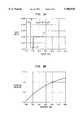
- FIG. 1on coordinates of chromatic dispersion on the ordinate and wavelength on the abscissa, is a plot of typical characteristics for various fiber designs, including MWF, with plotted data extending over a wavelength range encompassing both windows.
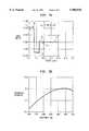
- FIG. 2on coordinates of dispersion and wavelength, are dispersion plots, showing nominal values and expected production excursions from nominal values for an illustrative MWF design.
- FIG. 3plots dispersion slope as a function of wavelength for the fiber plotted on FIG. 2.
- FIG. 4on coordinates of delta value (A) and radial position, is a plot of index profile for the MWF of Example 1.
- FIGS. 5A-5B, 6A-6B and 7A-7Bare paired index profile plots and nominal dispersion plots for alternative MWF structures, which, taken together, serve as basis for a discussion of design variations for achieving particular operating characteristics.
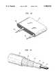
- FIG. 8is a perspective view of an MWF, dual coated in accordance with conventional practice.
- FIG. 9is a perspective view of one form of cable structure containing grouped MetroWave fibers.
- FIG. 10is a perspective view of an AccuRibbon® parallel fiber array.
- FIG. 11is a perspective view of a cable containing several FIG. 10 fiber arrays.
- FIG. 12is a schematic diagram of a metropolitan fiber system.
- FIG. 13is a schematic diagram of a multi-stage optical amplifier accommodating dual-window WDM operation, and suitable for use in the system of FIG. 12.
- Dispersion--Without a modifierrefers to chromatic dispersion, a linear effect by which different spectral components of a transmitted signal have different group velocities--generally in fiber structures under discussion, as dependent on the combined effects of material properties (material dispersion) and fiber design (waveguide dispersion). In digital systems, primarily addressed, dispersion causes pulse spreading and limits capacity.
- Non-Linear Dispersion--Signal distortionwhich increases more than linearly--e.g., quadratically--as a function of increasing power density.
- 4 WMis a significant form of non-linear dispersion here addressed, constituting the main capacity limitation on state-of-the-art WDM systems.
- compensationmakes use of relatively short lengths of compensating fiber of large order of magnitude and of opposite sign both relative to fiber being compensated.
- Preferred systems of the invention, discussed,generally do not provide for dispersion compensation, although neither form of compensation is precluded for still greater system capacity.
- Wavelength Division Multiplexing(WDM)--Providing for multi-channel operation within a single fiber. Channels of a set are sufficiently closely spaced to enable simultaneous amplification by an individual amplifier. Contemplated spacings, e.g., ⁇ 100 GHz between adjacent channels of a set, are descriptive of "Dense Wavelength Division Multiplexing" (DWDM), and the term "WDM", without a modifier, is intended to be inclusive of DWDM. Fiber (MWF) and systems of the invention are designed to support at least one WDM set in each of the 1310 nm and 1550 nm windows. Without a modifier, the term is not intended to be generic to "coarse WDM”.
- DWDMDistributed Wavelength Division Multiplexing
- the termrefers to combining/separating WDM channel sets (or "bands") associated with individual optical amplifiers--so that a coarse WDM provides for combining/routing multiple bands associated with multiple amplifiers.
- the termis used with reference to multiple bands within a window, as well as to bands within separate windows.
- State-of the-art optical fiberis "silica-based”.
- Delta ( ⁇ )--Relative index of refraction values--as used for measuring fiber profilethe fractional value of change in index from that of the outer cladding, divided by the index of the outer cladding.
- Fiber of the inventionis invariably single-mode down to a wavelength shorter than that of intended operation in the 1310 nm window (down to a "cut-off wavelength" at which the fiber becomes two-mode).
- Core--Innermost region of the fiber with primary responsibility for guidingIt is constituted of material of greater index of refraction than that of the clad. Its radial dimension is from the center of the fiber to the onset of material of index equal to or less than that of the outer cladding.
- An idealized corecontains no material of as low a value of refractive index as that of the outer cladding, although unintended deviations such as the dip characteristic of MCVD may conceivably result in a drop to that value.
- silica-based fiberof primary interest for relevant communication systems in the foreseeable future, there are two such windows, often identified as the 1310 nm and the 1550 nm windows.
- 1310 nm Window--Range of wavelength values considered to define the windowincluding 1310 nm--varying to some extent depending on system needs; for illustrative purpose, from 1260 nm to 1360 nm.
- 1550 nm Window--Range of wavelength values considered to define the windowincluding 1550 nm--varying to some extent depending on system needs; for illustrative purposes, from 1460 nm to 1620 nm.
- the operating windowmust avoid dispersion values either too low (from the standpoint of 4 WM) or too high (for specified bit-rate/distance). There is an operating window both at 1310 nm and at 1550 nm.
- Terminal or Terminal Equipment--Equipmententailing conversion from electrical to optical (E/O conversion) or from optical to electrical (O/E conversion)--i.e., as between the optical signal transmitted through a fiber and its electrical analog as introduced prior to conversion or extracted after conversion.
- a terminalmay be at a terminus of the system--operating as transmitter or receiver. Alternatively, it may define a terminus of a "fiber span" where it may operate as a "repeater” between successive fiber spans--as needed to avoid excessive growth in dispersion or excessive deterioration in S/N.
- Node--position providing signal accesse.g. for optical amplification, for addition or routing (add/drop), or for spectral inversion.
- signal processing at a nodedoes not provide for E/O or O/E conversion (the term, "terminal" being reserved for that purpose).
- Span--Without a modifierthe term specifies fiber length between terminals--between a first terminal providing for E/O and a second terminal providing for O/E.
- a spanis generally constituted of a series of amplifier spans.
- the primary thrust of the advanceis a fiber suitable for medium length, high speed, Wavelength Division Multiplexing (WDM) transmission simultaneously in both the 1310 nm and 1550 nm windows.
- WDMWavelength Division Multiplexing
- the new fiberhas a needed dispersion--here specified as of absolute magnitude between 1 and 8 ps/nm-km, now in regions of both windows.
- 4-wave mixing (4 WM)becomes more limiting for WDM systems.
- FIG. 1plots typical dispersion values for a variety of fiber types as a function of wavelength.
- the figureincludes "forbidden regions” representing regions inappropriate for system use based on common design criteria--region 10 of too great a loss, e.g., greater than 0.5 dB/km, due to --OH absorption at the "water peak”, and region II of too low dispersion shown as in the range of -2 to +2 ps/nm-km.
- the ⁇ 2 ps/nm-km values of dispersion boundary in the Figurerefer to preferred minima.
- System designsmay provide for WDM channels of extreme dispersion values of ⁇ 1.5 ps/nm-km or even ⁇ 1 ps/nm-km. Plotted limits for dispersion and water peak are for purposes of discussion--are not intended as rigorous limits. Values discussed as unacceptable are, in a sense, arbitrary--are the consequence of compromise, e.g., between capacity and span length.)
- unshifted single-mode fiberAs seen from curve 12, unshifted single-mode fiber (USF) has too low a dispersion at 1310 nm to allow WDM and too high a dispersion at 1550 nm to allow high speed transmission without the use of external dispersion compensation.
- NZF dispersionis too large at 1310 nm, and the particular commercial product (TrueWave®), plotted, has too low a dispersion, even for operation in the range of 1540-1480 nm, within the 1550 nm window.
- both fiber typesare limited in their operating windows by a large dispersion slope that limits usable bandwidth to a relatively narrow band of wavelengths within the desired dispersion range of 1.0-8.0 ps/nm-km--although to a bandwidth sufficient for present-day operation which is generally limited to a single WDM channel set.
- MWF, curve 14with its flattened slope and its zero dispersion wavelength of about 1400 nm, permits WDM in both windows--with operation over a bandwidth at least comparable both with USF in the 1310 nm window and NZF in the 1550 nm. window.
- SUFhas dual window capability, although with a more restricted total operating range than MWF.
- MWFis properly regarded as a dual window NZF design, and the new fiber may satisfy certain NZF requirements for operation at 1550 nm.
- provision for simultaneous operation in the 1310 nm windowmay result in somewhat smaller mode field diameter, and thus in effective area smaller than that of optimally designed present-day NZF.
- Effective areas for MWFare generally ⁇ 42 ⁇ m 2 --while they may overlap the value of 50 ⁇ m 2 typical of NZF, are typically in the range of 42-49 ⁇ m 2 .
- Effective areasee Opt. Lett., Vol. 19, No. 4, pp. 257-259 (Feb. 15, 1994).
- Decreasing effective areaincreases power density, and, accordingly, aggravates effects of nonlinear dispersion.
- the mechanism used for dispersion flattening in MWFmay not have been used previously. While certainly related, it is regarded as different from the mechanism responsible for earlier "flattened” fiber. Attainment of the then-desired nulled dispersion in both windows was the result of two separate material-waveguide crossovers, one at 1310 nm and the other at 1550 nm. Low slope accompanied change in sign of the slope between the null points.
- Attainment of "non-zero" dispersionrather than zero dispersion at system wavelengths in the transparency windows, generally precludes dispersion null points in either window--any long-wavelength crossover is necessarily at a wavelength value well beyond that of any intended carrier wavelength in the 1550 nm window.
- Low dispersion slopea requirement for all MWF designs, is a consequence of a multiple-layer structure such as that shown in FIG. 4.
- the depressed index region 41is of particular importance.
- Low wavelength dependence of dispersion(curve 30 of FIG. 3) is due to compensation of two phenomena. In general, group delay increases with wavelength, a prime determinant of dispersion slope at system wavelengths in bulk silica and in usual silica-based fiber.
- Reduced index of refraction of the trench of 0.05%--preferably of 0.1%--relative to the outer claddingflattens the dispersion sufficiently to assure a substantial region of desired non-zero dispersion in each window (for a null point located at the nominal value of 1400 nm).
- the primary purpose of this increased-index regionis not dispersion flattening, but concerns minimization of bend loss.
- bending loss--on the value of A at the interface of the ring and succeeding regions (here of outcladding 43)is affected by the effective index seen by the traveling wave front relative to the outer cladding, while flattening depends primarily on the characteristics of the trench itself, so that introduction of the ring may reduce bend loss without significantly impacting slope.
- a typical dispersion curve for MetroWave fiberis shown in FIG. 2.
- the nominal dispersion (solid curve 20)is about +6 ps/nm-km at 1550 nm and -6 ps/nm-km at 1310 nm.
- these values of dispersionallow 10 Gb/s non-return-to-zero (NRZ) transmission for fiber lengths up to about 160 km without the need for dispersion compensation--adequate for contemplated systems over distances anticipated in metropolitan areas.
- NRZnon-return-to-zero
- WDMAt moderate power levels ( ⁇ 4 dBm/channel), WDM requires about 1 ps/nm-km for channels at spacings of 100 GHz (equivalent to 0.57 nm and 0.80 nm at 1310 nm and 1550 nm, respectively), and about 4 ps/nm-km for spacings of 50 GHz (equivalent to 0.29 nm and 0.40 nm at 1310 nm and 1550 nm, respectively).
- WDM operating windowsFrom FIG. 1) are 1260 to 1360 nm and 1460 to 1620 nm for 100 GHz spacings, equivalent to 210 and 194 transmission channels, respectively.
- Curve 30 of FIG. 3shows a dispersion slope of value within the approximate range of 0.03-0.04 ps/nm 2 -km in the 1550 nm window. As compared with a value of 0.075 ps/nm 2 -km characteristic of NZF, the lower slope of MWF permits a comparable operating range in the 1550 nm window despite the lower dispersion null point.
- FIG. 4shows normalized refractive index difference ("delta") as a function of radial position for the four-region fiber which served as the basis for the preceding figures.
- the germano-silica core 40is surrounded by a trench 41, i.e., an annular region of depressed index, in this instance, composed of fluorine-doped silica.
- a raised index germano-silica ring 42Surrounding the trench is a raised index germano-silica ring 42, in turn within outer cladding region 43--in this specific instance, of undoped silica.
- Core region 40shows a depressed-index central region (or "dip") 44 characteristic of MCVD-produced fiber.
- "MCVD dip" 44serves no function, but does not unduly interfere with operation of the fiber.
- the abrupt discontinuities at the region boundariescan only be approached in real fiber.
- the change in indexcan occur over a region of less than 0.1 millimeter in a typical MCVD preform, corresponding to an index gradient of absolute value greater than 2%/mm. Agreement between the calculated results which use the idealized profile and measured results for actual fiber made from such a preform, demonstrates that MCVD is adequate for the purpose.
- Preform profile datais consistent with operating data for the fiber (on which profiling is not conveniently conducted).
- the core region 40consists of silica doped with germanium and extends from the center to a radius of about 3.5 ⁇ m.
- the germanium concentrationis adjusted to result in a radial variation, of the core delta as a function of radius, that can be described by the alpha profile law:
- rradial position within the core
- ais the core radius
- xis the profile shape parameter
- ⁇ 0is the delta value at the center of the fiber disregarding the central dip 44 (the peak index value of the core).
- the presence of the central dipis due to volatilization of germania from the exposed inner surface of the MCVD deposit during collapse and is inherent in usual MCVD processing. Although the presence of this region is unintended, its presence is assumed and its effect on the final fiber transmission properties is accounted for in the design.
- the germania concentration required to achieve the peak index level of 0.55%is approximately 7 weight percent.
- the core region of a preform fabricated by MCVD or OVDtypically consists of 5 or more annular layers, each made with a separate deposition pass.
- the germania concentration of each layeris adjusted to yield the desired radial index grading. If fabricated using the VAD process, the burner is designed to yield the desired gradient across the axially growing core region.
- Trench 41is silica which is down-doped with fluorine. It may also contain small amounts of germania or other dopant, e.g., to lessen strain or for fine profile adjustment.
- the nominal width of the trench in the drawn fiberis 2.5 ⁇ m.
- MCVDor OVD
- this regionconsists of about four (generally identical) deposition passes.
- VADa single, axially-grown layer forms the trench region. Achieving the well-defined fluorine-doped region with OVD or VAD is problematic because of fluorine diffusion in the highly porous soot boule. As discussed, diffusion may be minimized by partially or fully vitrifying individual regions as deposited. Vitrification at this stage may be carried out in a fluorine-containing environment to lessen volatilization-loss as well.
- Ring 42consists of silica doped primarily with germanium.
- the nominal delta of +0.07%requires a germania concentration of about 1 wt. %--an index increase ⁇ 0.05% relative to the outer cladding is effective in limiting mode spreading, and substantially reduces bending loss.
- the nominal width of the ringis 1.5 ⁇ m.
- this regioncorresponds with a few MCVD or OVD deposited layers, or with a single axially-grown VAD layer.
- the outercladding 43is undoped silica. It may be consist, in its entirety, of material deposited by one of the standard vapor-transport fiber fabrication processes, or it may, in part, be produced from an overcladding tube forming part of a composite preform.
- the outer claddingextends from the outer diameter of ring 42 to the outer diameter of the fiber, typically of a fiber nominally of 125 ⁇ m o.d.
- Table 1summarizes the values of the 9 parameters that specify the index profile of MWF 14 shown in FIG. 1.
- Nominal Valueis the targets for attaining desired mode field radius, dispersion profile, and bending loss.
- Exected Tolerancedefined the ranges required to maintain dispersion within a range of ⁇ 1 ps/nm-km about nominal values.
- Table 2lists ranges of parameter values of MWF. It should be kept in mind that values listed are minima and maxima for individual parameters, and do not represent a design prescription as taken together. For example, combining maximum values--or alternatively minimum values--of all listed parameters, will likely not result in effective design. Effective design must satisfy both shifting and slope flattening criteria described above.
- profile valuesare in terms of delta values.
- This practiceis useful in two regards: absolute values of index are difficult to measure; and, to first approximation, fiber parameters, with the exception of loss, scale as the relative rather than absolute values of index.
- Replacing the undoped silica outer cladding of the fiber of FIG. 4, e.g., with down-doped materialhas no first order effect on dispersion slope so long as other regions (core, trench, ring) are changed accordingly--i.e., so long as delta values are not altered.
- increasing index of the outer claddinghas little affect on such properties, concomitant need to increase core dopant concentration, to maintain ⁇ , may increase loss to undesirable levels.
- MCVDfacilitates attainment of such down-doped regions, e.g., by use of suitable MCVD substrate tubes and/or overcladding tubes.
- FIGS. 5A-5B, 6A-6B and 7A-7Billustrate the extensive design and dispersion variations studied.
- FIGS. 6A-6Bare illustrative of the fiber of FIG. 4 (two annular regions, i.e., reduced index "trench” 61 and increased index “ring” 62, intermediate core 60 and outer cladding 63).
- FIGS. 5A-5Brepresent MWF designs with but a single annular region 51 (trench 51), intermediate core 50, and outer cladding 52.
- FIGS. 7A-7Bare based on a structure providing for three annular regions 71, 72, 73 about core 70--three successive regions of successively reduced, increased, and reduced index, relative to the outer cladding 74. While the profiles of FIGS.
- 6A and 7Ainclude characteristic "MCVD dips"--depressed regions 64 and 75, respectively, the schematic profile of FIG. 5 does not. Study has included a variety of profiles, many of more gradual change in delta value; many including additional regions. In general, design criteria concerning such variations are consistent with general experience.
- FIG. 8depicts a dual coated MWF 80, with primary coating 81 and secondary coating 82.
- Fiber 80consists of core region 83 and clad region 84.
- the cladis shown as including trench 85 and outer cladding 86.
- FIG. 9depicts one form of commercial cable described in AT&T Lightguide Cable, December, 1990. It is constituted of two bundles 90, each bundle containing 12 color-coded fibers 91, held together by an encircling covering 92. Individual fibers 91 are of the general design of that of FIG. 8, but in this instance, include a tertiary coating provided with a color identifier.
- the complete structureincludes cable-filling compound 94, core tube 93 and two protective structures each constituted of a water-blocking tape 95 and a polyethylene jacket 96, each structure reinforced by steel wires 97.
- FIG. 10shows a commercially-available parallel fiber array, known as AccuRibbon®.
- the commercial articleconsists of 12 fibers 100 and matrix material 101.
- FIG. 11shows a cable containing grouped fibers in the form of planar arrays 110.
- Crossply sheath 111is filled with cable-filling compound 112.
- the particular structure shownis an under-water armored cable, including overwrappings constituting conductive shield 113, coated stainless steel protective layer 114, and bonded jacket 115.
- MWF designsare profiled to reduce dispersion slope. Most effective flattening relies on introduction of steep index variations.
- MCVDOne fiber fabrication process in particular, MCVD.
- soot processesmay be modified to better enable retention of steep gradients, e.g., by periodically halting deposition and consolidating in step-wise fashion, with a consolidation step for each deposited layer or group of layers.
- MCVD support tube--withinwhich deposition takes place in the course of preform fabrication, itself, may provide down-doped (or up-doped) regions resistant to dopant migration during subsequent deposition. It is conceivable that an early described variation of soot processing, inside vapor deposition (IVD), may serve the purpose of the MCVD support tube.
- the MetroWave fiberoffers high-capacity system operation without need for the dispersion compensation required for dual-window operation--particularly for dual-window WDM operation--with NZF or USF.
- Provision for compensation--either using concatenation or by use of high-dispersion specialty fiber--in principleat least, permits operation of NZF or USF in its "closed" window.
- Dispersion compensationis costly and adds engineering complexity.
- dual window operationis offered by a fiber which is simply shifted (but unflattened).
- Such a fibere.g., fiber 15 of FIG.
- FIG. 12is an illustrative MetroWave system.
- the schematic diagramincludes Metro Backbone rings 120 and 121, generally configured as SONET rings. Rings contain from 8 to 16 nodes 122 defining 10-40 km-length nodal spans 123. Ring circumference is typically 120-200 km.
- a usual node 122is provided with an optical amplifier and means for adding or dropping channels. Designated channels may be added or dropped at a node, while at the same time, other channels, perhaps amplified, will be retained in the ring and transmitted to a succeeding node.
- the Figureshows two rings 120 and 121 linked through a common node. In operation, any given channel is enabled to travel from any particular node to any other node, either on the same ring or on the adjoining ring. Design experience has ordinarily led to a maximum "wavelength path" distance on the order of 300 km.
- Each node 122likely includes an optical router (a "WDM” or "DWDM”, with such term now designating the element responsible for performing the multiplexing/demultiplexing functions fundamental to state-of-the-art WDM).
- a nodemay include provision for adding/dropping. Add/drop equipment accomodates local distribution of electrical, rather than photonic, signals, and must include means for O/E or E/O conversion. Two conventional forms of local distribution are shown--access ring 124 and access star 125. It is anticipated that photonic local distribution will replace electronic distribution. Photonic distribution systems may continue to take the form of rings or stars--possibly constructed of MetroWave fiber of the invention, although, less costly USF may be adequate for the purpose.
- the Figureshows connection made with long-haul networks 126 and 127. Utilization of MetroWave fiber for long haul, as discussed, is not precluded. For usual long-haul purposes, however, it is expected that a form of NZF fiber will continue to be preferred.
- FIG. 13is a schematic representation of a multi-stage 1310/1550 nm optical amplifier, representative of amplifiers included in the nodes of the Metro Backbone rings of FIG. 12.
- the amplifier shownis suitably used with the claimed systems, providing for simultaneous amplification of WDM channel sets in both windows.
- the amplifier shownprovides for first separating the two bands--the 1310 band and the 1550 band--as introduced on incoming fiber line 130. Band separation is accomplished by WDM 132, properly regarded as "coarse WDM" 132 (to differentiate it from routers accommodating closely spaced channels of a WDM channel set).
- the 1310 nm and 1550 nm bands, now separated at 132,are routed along fibers 133 and 134, respectively, until coarse WDMs 135 separate them into component WDM sets.
- the 1310 nm bandis shown as yielding three WDM sets 136, 137 and 138, which then pass through amplifiers 139, 140 and 141, thence to be recombined at coarse WDM 140.
- the 1550 bandis separated into WDM sets 141, 142, 143, 144 to be amplified respectively at amplifiers 145, 146, 147, 148, and recombined by coarse WDM 149.
- the amplified setstravel through fiber lines 150 and 151, are combined by coarse WDM 152, and exit over line 153.
- the multi-stage amplifier of FIG. 13is designed with a view to today's state-of-the-art.
- Present day EDFAshave a greater bandwidth--perhaps 35 to 40 nm--owing to use of gain equalization filters which lessen the structure of the naturally occurring gain spectrum. Even this expanded bandwidth will be insufficient for the entire 1550 band, now made available by the present invention which, by one measure, encompasses the 160 nm range from 1460 nm to 1620 nm.
- the arrangement shown in the Figureprovides for four amplifiers, with only 147 and 148 constituted of erbium-doped fiber.
- the design shownassumes amplifiers 145 and 146 to be Raman amplifiers, operating over the shorter wavelength portion of the 1550 nm band. WDM sets of the 1310 band are amplified by Raman amplifiers, as well.
- Amplifiers 139, 140 and 141are designed to accommodate the three subbands 136-138, together representing the usable 1260 nm-1360 nm window illustratively available to MWF.
- Raman amplifiersshown as operating in the 1310 nm window as well as for the two shorter wavelength subbands in the 1550 nm window, have enabled a useable bandwidth of 25-30 nm (see U.S. Pat. No. 5,623,508, issued Apr. 22, 1997). Comparable with a state-of-the-art EDFA, a major part of the 1260-1360 nm 1310 nm window, now made available, is accommodated by a three-stage Raman amplifier.
Landscapes
- Physics & Mathematics (AREA)
- Chemical & Material Sciences (AREA)
- Dispersion Chemistry (AREA)
- General Physics & Mathematics (AREA)
- Optics & Photonics (AREA)
- Electromagnetism (AREA)
- Engineering & Computer Science (AREA)
- Computer Networks & Wireless Communication (AREA)
- Signal Processing (AREA)
- Optical Communication System (AREA)
- Lasers (AREA)
- Optical Fibers, Optical Fiber Cores, And Optical Fiber Bundles (AREA)
Abstract
Description
______________________________________MWF Specification Table______________________________________Attenuation at 1550 nm ≦0.25 dB/kmAttenuation at 1310 nm ≦0.50 dB/kmEffective area at 1550 nm ≧42 μm.sup.2Core eccentricity Less than or equal to 0.8μmCladding diameter 125 ± 2.0 μmCut-off wavelength <1250 nmZero-dispersion wavelength 1350 nm-1450 nmDispersion at 1310 nm -3.0 to -8 ps/nm-kmDispersion at 1550 nm +3.0 to +8 ps/nm-kmDispersion slope at 1550 nm 0.01-0.05 ps/nm.sup.2 -kmMacrobendingloss at 1310 nm <0.5 dB (1 turn, 32 mm)Macrobending loss at 1550 nm <0.05 dB (100 turns, 75 mm)Coating diameter 245 ± 10μmProof test 100 kpsiReel lengths 2.2, 4.4, 6.4, 8.8, 10.8, 12.6, 19.2 km______________________________________
Δ(r)=Δ.sub.0 1-(r/a).sup.a !
TABLE 1______________________________________ Nominal ExpectedParameter Value Tolerance______________________________________Core .increment. 0.55% ±0.02%Core α 5 ±1Core Radius 3.5 μm ±0.1 μmTrench .increment. -0.24% ±0.025%Trench Width 2.5 μm ±0.25 μmRing .increment. 0.07% ±0.007%Ring Width 1.5 μm ±0.25 μmOuter 0.0% N/ACladding .increment.Outer 55 μm N/ACladdingWidth______________________________________
TABLE 2______________________________________Parameter Range______________________________________Core .increment. 0.40 to 0.60%Core α 1 to ∞Core Radius 3.0 to 4.0 μmTrench .increment. -0.1 to -0.3%Trench Width 1.5 to 6.0 μmRing .increment. 0.0 to 0.3%Ring Width 1 to 5 μmOuter Cladding .increment. NAOuter Cladding NAWidth______________________________________
Claims (18)
Priority Applications (6)
| Application Number | Priority Date | Filing Date | Title |
|---|---|---|---|
| US09/025,195US5905838A (en) | 1998-02-18 | 1998-02-18 | Dual window WDM optical fiber communication |
| TW088100786ATW429326B (en) | 1998-02-18 | 1999-01-19 | Dual window WDM optical fiber communication |
| CA002260478ACA2260478C (en) | 1998-02-18 | 1999-01-26 | Dual window wdm optical fiber communication |
| DE69943364TDE69943364D1 (en) | 1998-02-18 | 1999-02-09 | Fiber optic communication with wavelength division multiplexing in two optical windows |
| EP99300952AEP0938001B1 (en) | 1998-02-18 | 1999-02-09 | Dual window WDM optical fiber communication |
| JP03962699AJP3732669B2 (en) | 1998-02-18 | 1999-02-18 | Double window WDM optical fiber communication |
Applications Claiming Priority (1)
| Application Number | Priority Date | Filing Date | Title |
|---|---|---|---|
| US09/025,195US5905838A (en) | 1998-02-18 | 1998-02-18 | Dual window WDM optical fiber communication |
Publications (1)
| Publication Number | Publication Date |
|---|---|
| US5905838Atrue US5905838A (en) | 1999-05-18 |
Family
ID=21824596
Family Applications (1)
| Application Number | Title | Priority Date | Filing Date |
|---|---|---|---|
| US09/025,195Expired - LifetimeUS5905838A (en) | 1998-02-18 | 1998-02-18 | Dual window WDM optical fiber communication |
Country Status (6)
| Country | Link |
|---|---|
| US (1) | US5905838A (en) |
| EP (1) | EP0938001B1 (en) |
| JP (1) | JP3732669B2 (en) |
| CA (1) | CA2260478C (en) |
| DE (1) | DE69943364D1 (en) |
| TW (1) | TW429326B (en) |
Cited By (107)
| Publication number | Priority date | Publication date | Assignee | Title |
|---|---|---|---|---|
| US6049418A (en)* | 1998-02-06 | 2000-04-11 | Lucent Technologies, Inc. | Noise figure in optical amplifiers with a split-band architecture |
| US6091538A (en)* | 1996-12-09 | 2000-07-18 | Kokusai Denshin Denwa Kabushiki Kaisha | Gain equalizing apparatus |
| US6151160A (en)* | 1998-10-05 | 2000-11-21 | Tyco Submarine Systems Ltd. | Broadband Raman pre-amplifier for wavelength division multiplexed optical communication systems |
| US6236496B1 (en)* | 1996-12-11 | 2001-05-22 | Nippon Telegraph And Telephone Corporation | Optical fiber amplifier and optical amplification method |
| WO2001038911A1 (en)* | 1999-11-22 | 2001-05-31 | Corning Incorporated | Dispersion shifted large effective area waveguide fiber |
| US6292613B1 (en)* | 1998-06-17 | 2001-09-18 | Fort Fibres Optiques Recherche Et Technologie | Fiber coated with a crosslinked epoxidized-polydiene oligomer |
| US6356384B1 (en)* | 1998-03-24 | 2002-03-12 | Xtera Communications Inc. | Broadband amplifier and communication system |
| US20020035640A1 (en)* | 1999-10-12 | 2002-03-21 | Greenberg Albert Gordon | Recovery method for an optical network |
| WO2002007270A3 (en)* | 2000-07-14 | 2002-04-18 | Tycom Us Inc | Hybrid fiber amplifier |
| WO2001076350A3 (en)* | 2000-04-11 | 2002-04-25 | Xtera Communications Inc | Broadband amplifier and communication system |
| US6385384B1 (en)* | 1999-03-15 | 2002-05-07 | Corning Incorporated | Glasses containing rare earth fluorides |
| US6404964B1 (en)* | 1998-05-01 | 2002-06-11 | Corning Incorporated | Dispersion managed optical waveguide and system with distributed amplification |
| WO2002019576A3 (en)* | 2000-08-31 | 2002-06-20 | Pirelli Cavi E Sistemi Spa | Optical transmission link with low slope, raman amplified fiber |
| US6433920B1 (en) | 2000-04-27 | 2002-08-13 | Jds Uniphase Corporation | Raman-based utility optical amplifier |
| US20020131160A1 (en)* | 2001-03-15 | 2002-09-19 | Mcnicol John D. | Dispersion management for long-haul high-speed optical networks |
| US20020140942A1 (en)* | 2001-02-17 | 2002-10-03 | Fee Michale Sean | Acousto-optic monitoring and imaging in a depth sensitive manner |
| US6473548B2 (en)* | 1999-12-02 | 2002-10-29 | Sumitomo Electric Industries, Ltd. | Multiple fiber optical cable and method of manufacturing multiple fiber optical cable |
| US20020163685A1 (en)* | 2001-05-01 | 2002-11-07 | Swanson Eric Arthur | System and method for routing working and protect paths |
| US6490397B2 (en) | 1999-12-13 | 2002-12-03 | Sumitomo Electric Industries, Ltd. | Optical fiber |
| US20020196430A1 (en)* | 2000-12-22 | 2002-12-26 | May Gregory D. | Measuring optical signal power in an optical system |
| WO2002035741A3 (en)* | 2000-10-25 | 2003-01-16 | Teraray Inc | System and method for optical fiber telecommunication by simultaneous transmission in two optical windows |
| US6516125B1 (en)* | 1998-12-17 | 2003-02-04 | Lg Cable Ltd. | Dispersion shifted optical fiber having triple clad |
| US6532101B2 (en) | 2001-03-16 | 2003-03-11 | Xtera Communications, Inc. | System and method for wide band Raman amplification |
| US20030058899A1 (en)* | 1996-12-23 | 2003-03-27 | Xtera Communications, Inc., A Delaware Corporation | Optical amplification using polarization diversity pumping |
| US6542665B2 (en) | 2001-02-17 | 2003-04-01 | Lucent Technologies Inc. | GRIN fiber lenses |
| US6556744B1 (en)* | 2001-10-12 | 2003-04-29 | Nortel Networks Limited | Reduction of dispersion effects in optical transmission fibre systems |
| US6556758B2 (en)* | 1999-04-16 | 2003-04-29 | Sumitomo Electric Industries, Ltd. | Optical fiber and optical transmission line including the same |
| US6567208B1 (en)* | 2000-04-25 | 2003-05-20 | Sprint Communications Company, L.P. | Amplification of a C-band and L-band of a optical signal using a common laser signal |
| US6574037B2 (en) | 1998-06-16 | 2003-06-03 | Xtera Communications, Inc. | All band amplifier |
| US6577800B2 (en) | 1998-12-18 | 2003-06-10 | Pirelli Cavi E Sistemi S.P.A. | Optical fiber for metropolitan and access network systems |
| US6584255B2 (en)* | 2001-04-16 | 2003-06-24 | Kddi Submarine Cable Systems Inc. | Method for manufacturing optical fiber cable with optical fibers whose chromatic dispersion value are uniformed |
| US6587259B2 (en) | 2001-07-27 | 2003-07-01 | Xtera Communications, Inc. | System and method for controlling noise figure |
| US20030128948A1 (en)* | 1998-06-19 | 2003-07-10 | Pirelli Cavi E Sistemi S.P.A. | Optical fiber having low non-linearity for WDM transmission |
| US20030133183A1 (en)* | 2001-08-15 | 2003-07-17 | Photon-X, Inc. | Ultra-wide bandwidth optical amplifier |
| US6597493B2 (en)* | 2000-05-05 | 2003-07-22 | The Regents Of The University Of Michigan | Nonlinear fiber amplifiers used for a 1430-1530nm low-loss window in optical fibers |
| EP1329751A1 (en)* | 2002-01-22 | 2003-07-23 | Fujikura Ltd. | Optical fiber with dispersion characteristics allowing WDM transmission over S, C, and L bands |
| US6600592B2 (en) | 1998-03-24 | 2003-07-29 | Xtera Communications, Inc. | S+ band nonlinear polarization amplifiers |
| US6603594B2 (en) | 1998-06-16 | 2003-08-05 | Xtera Communications, Inc. | Multi-stage optical amplifier and broadband communication system |
| US6602002B1 (en)* | 1998-02-20 | 2003-08-05 | Lucent Technologies Inc. | High capacity optical transmission arrangement |
| US20030147127A1 (en)* | 2001-11-29 | 2003-08-07 | Duling Irl N. | Amplitude balancing for multilevel signal transmission |
| US6606187B1 (en) | 1998-03-24 | 2003-08-12 | The Regents Of The University Of Michigan | Nonlinear fiber amplifiers used for a 1430-1530 nm low-loss window in optical fibers |
| US6606437B1 (en)* | 1999-02-22 | 2003-08-12 | The Furukawa Electric Co., Ltd. | Optical transmission line, negative dispersion optical fiber used for the optical transmission line, and optical transmission system comprising optical transmission line |
| US6606438B2 (en) | 1998-04-22 | 2003-08-12 | Corning Incorporated | Low dispersion slope fiber |
| US6618192B2 (en) | 1998-06-16 | 2003-09-09 | Xtera Communications, Inc. | High efficiency raman amplifier |
| US20030180019A1 (en)* | 2000-03-03 | 2003-09-25 | Tirloni Bartolomeo Italo | Optical fiber for wdm transmission |
| US6633715B2 (en)* | 2001-12-06 | 2003-10-14 | Fitel Usa Corp. | Optical fiber having negative dispersion, negative dispersion slope and large effective area |
| US6633713B2 (en) | 1998-12-18 | 2003-10-14 | Pirelli Cavi E Sistemi S.P.A. | Optical system and method having low loss and non-linear effects |
| US20030202770A1 (en)* | 2002-01-03 | 2003-10-30 | Garito Anthony F. | Optical waveguide amplifiers |
| US6647191B2 (en) | 2000-08-16 | 2003-11-11 | Corning Incorporated | Optical fiber with large effective area, low dispersion and low dispersion slope |
| EP1055945A3 (en)* | 1999-05-24 | 2003-11-12 | Lucent Technologies Inc. | Optical fiber having negative dispersion and low slope in the erbium amplifier region |
| US20030210877A1 (en)* | 2000-12-12 | 2003-11-13 | Berkey George E. | Large effective area optical fiber |
| US6657777B1 (en)* | 2001-12-05 | 2003-12-02 | Cisco Technology, Inc | Interleaved lumped raman amplifier structure based on highly nonlinear fibers for densely spaced WDM channels |
| US20030223682A1 (en)* | 2002-05-30 | 2003-12-04 | Susumu Kinoshita | Optical add/drop node and method |
| US20040008404A1 (en)* | 2002-07-11 | 2004-01-15 | Fujitsu Network Communications, Inc. | Distributed raman amplifier for optical network and method |
| US20040022509A1 (en)* | 2002-07-31 | 2004-02-05 | Pushkar Tandon | Non-zero dispersion shifted optical fiber with depressed core having large effective area, low slope and low dispersion |
| US20040028329A1 (en)* | 2001-02-17 | 2004-02-12 | Reed William Alfred | Fiber devices using GRIN fiber lenses |
| US20040028359A1 (en)* | 2000-08-31 | 2004-02-12 | Tirloni Bartolomeo Italo | Optical transmission link with low slope, raman amplified fiber |
| US6693737B2 (en) | 1998-03-24 | 2004-02-17 | Xtera Communications, Inc. | Dispersion compensating nonlinear polarization amplifiers |
| US20040052486A1 (en)* | 2002-09-13 | 2004-03-18 | Fitel Usa Corp. | Optical fibers and modules for dispersion compensation with simultaneous raman amplification |
| WO2004025346A1 (en)* | 2002-09-11 | 2004-03-25 | The Furukawa Electric Co.,Ltd. | Optical fiber tape core of low polarization mode dispersion characteristic and method for measuring dynamic viscoelasticity of the core |
| US20040067034A1 (en)* | 2002-07-31 | 2004-04-08 | Rosenblum Steven S. | Non-zero dispersion shifted optical fiber having large effective area, low slope and low zero dispersion |
| US6724527B2 (en)* | 2000-09-19 | 2004-04-20 | Sumitomo Electric Industries, Ltd. | Optical amplifier and optical transmission system using same |
| US20040096171A1 (en)* | 2002-06-28 | 2004-05-20 | The Furukawa Electric Co., Ltd. | Optical fiber and optical transmission system using the optical fiber |
| US20040101236A1 (en)* | 2002-11-21 | 2004-05-27 | Kelly Colin Geoffrey | Reconfigurable optical add/drop multiplexer with buried dispersion compensation module |
| US6751389B2 (en)* | 1998-09-21 | 2004-06-15 | Pirelli Cavi E Sistemi S.P.A. | Optical fiber for extended wavelength band |
| US20040126074A1 (en)* | 2002-12-31 | 2004-07-01 | Bickham Scott R. | Dispersion flattened NZDSF fiber |
| US6760112B2 (en) | 2001-02-17 | 2004-07-06 | Lucent Technologies Inc. | Grin-fiber lens based optical endoscopes |
| US6760148B2 (en) | 1998-03-24 | 2004-07-06 | Xtera Communications, Inc. | Nonlinear polarization amplifiers in nonzero dispersion shifted fiber |
| US20040141703A1 (en)* | 2003-01-22 | 2004-07-22 | Sung-Koog Oh | Optical fiber |
| US20040141705A1 (en)* | 2003-01-20 | 2004-07-22 | Jeong-Sik Cho | Wide-band dispersion controlled optical fiber |
| US6768848B2 (en) | 2001-03-30 | 2004-07-27 | The Furukawa Electric Co., Ltd. | Optical fiber and optical transmission line using the same, and optical transmission system |
| US6778321B1 (en) | 2002-03-15 | 2004-08-17 | Xtera Communications, Inc. | Fiber optic transmission system for a metropolitan area network |
| EP1275991A3 (en)* | 2001-07-09 | 2004-08-25 | The Furukawa Electric Co., Ltd. | Optical fiber and optical signal transmission system using this optical fiber |
| US20040208506A1 (en)* | 2002-03-28 | 2004-10-21 | Susumu Kinoshita | Flexible open ring optical network and method |
| US20040208505A1 (en)* | 2002-03-27 | 2004-10-21 | Susumu Kinoshita | Method and system for testing during operation of an open ring optical network |
| US6810214B2 (en) | 2001-03-16 | 2004-10-26 | Xtera Communications, Inc. | Method and system for reducing degradation of optical signal to noise ratio |
| US6819478B1 (en) | 2002-03-15 | 2004-11-16 | Xtera Communications, Inc. | Fiber optic transmission system with low cost transmitter compensation |
| US20040258412A1 (en)* | 2001-11-19 | 2004-12-23 | The Furukawa Electric Co., Ltd. | Broadband optical fiber |
| US6839164B2 (en)* | 2000-03-29 | 2005-01-04 | Hitachi, Ltd. | Optical transmission equipment and supervisory system thereof |
| US6865326B2 (en)* | 2000-02-07 | 2005-03-08 | Sumitomo Electric Industries, Ltd. | Optical transmission line and optical transmission system |
| US20050058418A1 (en)* | 2003-01-23 | 2005-03-17 | Sterlite Optical Technologies Limited | Dispersion optimized fiber having higher spot area |
| US20050063656A1 (en)* | 2003-09-24 | 2005-03-24 | Donald Jablonowski | Optical fiber for improved performance in S-, C- and L-bands |
| US6885498B2 (en) | 1998-06-16 | 2005-04-26 | Xtera Communications, Inc. | Multi-stage optical amplifier and broadband communication system |
| US6895153B2 (en) | 2002-12-24 | 2005-05-17 | Alcatel | Optical fiber for wavelength division multiplex transmission networks |
| US6901193B2 (en)* | 2001-07-16 | 2005-05-31 | The Furukawa Electric Co., Ltd. | Dispersion compensating optical fiber ribbon and optical transmission system using the same |
| US6954303B2 (en) | 1999-12-23 | 2005-10-11 | Xtera Communications, Inc. | Multi-stage optical amplifier and broadband communication system |
| US6985283B1 (en) | 1998-06-16 | 2006-01-10 | Xtera Communications, Inc. | Fiber-optic compensation for dispersion, gain tilt, and band pump nonlinearity |
| US20060008221A1 (en)* | 2004-07-12 | 2006-01-12 | The Furukawa Electric Co., Ltd. | Highly nonlinear optical fiber and highly nonlinear optical fiber module |
| US20060045528A1 (en)* | 2004-08-27 | 2006-03-02 | Fujitsu Network Communications, Inc. | System and method for modularly scalable architecture for optical networks |
| US7050687B2 (en) | 2002-02-15 | 2006-05-23 | Corning Incorporated | Low slope dispersion shifted optical fiber |
| US7054059B1 (en) | 2003-05-14 | 2006-05-30 | Cisco Technoloy, Inc. | Lumped Raman amplification structure for very wideband applications |
| US7058311B1 (en) | 2002-03-15 | 2006-06-06 | Xtera Communications, Inc. | System and method for dispersion compensation in an optical communication system |
| US7116905B2 (en) | 2002-03-27 | 2006-10-03 | Fujitsu Limited | Method and system for control signaling in an open ring optical network |
| US20070009218A1 (en)* | 2002-02-13 | 2007-01-11 | The Furukawa Electric Co., Ltd. | Optical fiber and optical transmission line and optical communication system including such optical fiber |
| US20070041688A1 (en)* | 2002-06-06 | 2007-02-22 | Draka Fibre Technology B.V. | Single mode optical fibre as well as optical communication system |
| US7197245B1 (en) | 2002-03-15 | 2007-03-27 | Xtera Communications, Inc. | System and method for managing system margin |
| US20070116418A1 (en)* | 2005-11-23 | 2007-05-24 | Mishra Snigdharaj K | Low attenuation non-zero dispersion shifted optical fiber |
| US20070274715A1 (en)* | 2003-09-20 | 2007-11-29 | Olaf Pichler | Node for an Optical Communication Network |
| CN100367053C (en)* | 2002-06-28 | 2008-02-06 | 古河电气工业株式会社 | Optical fibre for wavelength division multiplexed system and manufacturing method thereof |
| US9825726B2 (en) | 2016-01-25 | 2017-11-21 | Tyco Electronics Subsea Communications Llc | Efficient optical signal amplification systems and methods |
| US9967051B2 (en) | 2016-01-25 | 2018-05-08 | Tyco Electronics Subsea Communications Llc | Efficient optical signal amplification systems and methods |
| US11303379B1 (en) | 2020-11-05 | 2022-04-12 | Mellanox Technologies, Ltd. | Communication between data centers using a multi-core fiber |
| WO2022086863A1 (en)* | 2020-10-22 | 2022-04-28 | Ofs Fitel, Llc | Increasing total data capacity in optical transmission systems |
| US11378765B2 (en) | 2020-05-25 | 2022-07-05 | Mellanox Technologies, Ltd. | Intra data center and inter data center links using dual-wavelength multimode/singlemode multi-core fiber |
| US11561352B2 (en) | 2020-04-01 | 2023-01-24 | Mellanox Technologies, Ltd. | High density optical I/O inside a data center switch using multi-core fibers |
| US11630274B2 (en) | 2020-04-01 | 2023-04-18 | Mellanox Technologies, Ltd. | High-density optical communications using multi-core fiber |
| US20230139856A1 (en)* | 2021-11-02 | 2023-05-04 | Fujitsu Limited | Phosphorous doped fiber-based raman amplifier |
Families Citing this family (8)
| Publication number | Priority date | Publication date | Assignee | Title |
|---|---|---|---|---|
| FR2784198B1 (en) | 1998-10-05 | 2002-08-30 | Cit Alcatel | OPTICAL FIBER FOR USE IN WAVELENGTH MULTIPLEXED TRANSMISSION SYSTEM |
| WO2000031573A1 (en)* | 1998-11-26 | 2000-06-02 | Sumitomo Electric Industries, Ltd. | Optical fiber and optical transmission system including the same |
| CA2368327A1 (en)* | 2000-02-25 | 2001-08-30 | The Furukawa Electric Co., Ltd | Low-dispersion optical fiber and optical transmission system using the low-dispersion optical fiber |
| JP2007293351A (en)* | 2000-02-25 | 2007-11-08 | Furukawa Electric Co Ltd:The | Low dispersion optical fiber and optical transmission system using the low dispersion optical fiber |
| DE10010783A1 (en)* | 2000-03-04 | 2001-09-06 | Deutsche Telekom Ag | Single-mode optical fibre, has refractive index in second radial section that is less than that of outer section |
| JP2002162529A (en)* | 2000-11-28 | 2002-06-07 | Furukawa Electric Co Ltd:The | Optical fiber and optical communication system using the optical fiber |
| JP2003279780A (en) | 2002-01-15 | 2003-10-02 | Sumitomo Electric Ind Ltd | Optical fiber, optical fiber tape, optical cable and optical connector with optical fiber |
| FR2941540B1 (en)* | 2009-01-27 | 2011-05-06 | Draka Comteq France | MONOMODE OPTICAL FIBER HAVING ENHANCED EFFECTIVE SURFACE |
Citations (6)
| Publication number | Priority date | Publication date | Assignee | Title |
|---|---|---|---|---|
| US4217027A (en)* | 1974-02-22 | 1980-08-12 | Bell Telephone Laboratories, Incorporated | Optical fiber fabrication and resulting product |
| US4372647A (en)* | 1979-10-08 | 1983-02-08 | Nippon Telegraph & Telephone Public Corporation | Single mode optical fibers |
| US4435040A (en)* | 1981-09-03 | 1984-03-06 | Bell Telephone Laboratories, Incorporated | Double-clad optical fiberguide |
| US5327516A (en)* | 1993-05-28 | 1994-07-05 | At&T Bell Laboratories | Optical fiber for wavelength division multiplexing |
| US5611016A (en)* | 1996-06-07 | 1997-03-11 | Lucent Technologies Inc. | Dispersion-balanced optical cable |
| US5623508A (en)* | 1996-02-12 | 1997-04-22 | Lucent Technologies Inc. | Article comprising a counter-pumped optical fiber raman amplifier |
Family Cites Families (3)
| Publication number | Priority date | Publication date | Assignee | Title |
|---|---|---|---|---|
| CA2139957C (en)* | 1994-02-18 | 1999-02-09 | Andrew R. Chraplyvy | Multi-channel optical fiber communication system |
| US5715346A (en)* | 1995-12-15 | 1998-02-03 | Corning Incorporated | Large effective area single mode optical waveguide |
| JPH09233053A (en)* | 1995-12-22 | 1997-09-05 | Furukawa Electric Co Ltd:The | Optical signal transmission method |
- 1998
- 1998-02-18USUS09/025,195patent/US5905838A/ennot_activeExpired - Lifetime
- 1999
- 1999-01-19TWTW088100786Apatent/TW429326B/enactive
- 1999-01-26CACA002260478Apatent/CA2260478C/ennot_activeExpired - Fee Related
- 1999-02-09EPEP99300952Apatent/EP0938001B1/ennot_activeExpired - Lifetime
- 1999-02-09DEDE69943364Tpatent/DE69943364D1/ennot_activeExpired - Lifetime
- 1999-02-18JPJP03962699Apatent/JP3732669B2/ennot_activeExpired - Lifetime
Patent Citations (7)
| Publication number | Priority date | Publication date | Assignee | Title |
|---|---|---|---|---|
| US4217027A (en)* | 1974-02-22 | 1980-08-12 | Bell Telephone Laboratories, Incorporated | Optical fiber fabrication and resulting product |
| US4217027B1 (en)* | 1974-02-22 | 1986-07-15 | ||
| US4372647A (en)* | 1979-10-08 | 1983-02-08 | Nippon Telegraph & Telephone Public Corporation | Single mode optical fibers |
| US4435040A (en)* | 1981-09-03 | 1984-03-06 | Bell Telephone Laboratories, Incorporated | Double-clad optical fiberguide |
| US5327516A (en)* | 1993-05-28 | 1994-07-05 | At&T Bell Laboratories | Optical fiber for wavelength division multiplexing |
| US5623508A (en)* | 1996-02-12 | 1997-04-22 | Lucent Technologies Inc. | Article comprising a counter-pumped optical fiber raman amplifier |
| US5611016A (en)* | 1996-06-07 | 1997-03-11 | Lucent Technologies Inc. | Dispersion-balanced optical cable |
Non-Patent Citations (12)
| Title |
|---|
| AT & T Lightguide Cable, Issue 9, Dec., 1990, pp. 14, 19, 21.* |
| AT&T Lightguide Cable, Issue 9, Dec., 1990, pp. 14, 19, 21. |
| K. Okamoto, et al., "Dispersion Minimisation in single-mode fibres over a wide spectral range," Electronics Letters, Oct. 25, 1979, vol. 15, No. 22, pp. 729-731. |
| K. Okamoto, et al., Dispersion Minimisation in single mode fibres over a wide spectral range, Electronics Letters, Oct. 25, 1979, vol. 15, No. 22, pp. 729 731.* |
| K. S. Kim, et al., "Measurement of the nonlinear index of silica-core and dispersion-shifted fibers," Optical Letters, Feb. 15, 1994, vol. 19, No. 4, pp. 257-259. |
| K. S. Kim, et al., Measurement of the nonlinear index of silica core and dispersion shifted fibers, Optical Letters, Feb. 15, 1994, vol. 19, No. 4, pp. 257 259.* |
| M. Yamada, et al., "Broadband and gain-flattened amplifier composed of a 1.55 μm-band and a 1.58 μm-band Er3+ -doped fibre amplifier in a parallel configuration," Electronics Letters, Apr. 10, 1997, vol. 33, No. 8, pp. 710-711. |
| M. Yamada, et al., Broadband and gain flattened amplifier composed of a 1.55 m band and a 1.58 m band Er 3 doped fibre amplifier in a parallel configuration, Electronics Letters, Apr. 10, 1997, vol. 33, No. 8, pp. 710 711.* |
| P. B. Hansen, et al., "High sensitivity 1.3 μm optically preamplified receiver using Raman amplification," Electronics Letters, Nov. 7, 1996, vol. 32, No. 23, pp. 2164-2165. |
| P. B. Hansen, et al., High sensitivity 1.3 m optically preamplified receiver using Raman amplification, Electronics Letters, Nov. 7, 1996, vol. 32, No. 23, pp. 2164 2165.* |
| Y. Sun, et al., "An 80 nm Ultra wide Band EDFA With Low Noise Figure And High Output Power," ECOC 97, Sep. 22-25, 1997, Conference Pub. No. 448, pp. 69-72. |
| Y. Sun, et al., An 80 nm Ultra wide Band EDFA With Low Noise Figure And High Output Power, ECOC 97, Sep. 22 25, 1997, Conference Pub. No. 448, pp. 69 72.* |
Cited By (173)
| Publication number | Priority date | Publication date | Assignee | Title |
|---|---|---|---|---|
| US6091538A (en)* | 1996-12-09 | 2000-07-18 | Kokusai Denshin Denwa Kabushiki Kaisha | Gain equalizing apparatus |
| US6236496B1 (en)* | 1996-12-11 | 2001-05-22 | Nippon Telegraph And Telephone Corporation | Optical fiber amplifier and optical amplification method |
| US6833946B2 (en) | 1996-12-23 | 2004-12-21 | Xtera Communications, Inc. | Optical amplification using polarization diversity pumping |
| US20030058899A1 (en)* | 1996-12-23 | 2003-03-27 | Xtera Communications, Inc., A Delaware Corporation | Optical amplification using polarization diversity pumping |
| US6049418A (en)* | 1998-02-06 | 2000-04-11 | Lucent Technologies, Inc. | Noise figure in optical amplifiers with a split-band architecture |
| US6602002B1 (en)* | 1998-02-20 | 2003-08-05 | Lucent Technologies Inc. | High capacity optical transmission arrangement |
| US20020054427A1 (en)* | 1998-03-24 | 2002-05-09 | Islam Mohammed N. | Broadband amplifier and communication system |
| US6606187B1 (en) | 1998-03-24 | 2003-08-12 | The Regents Of The University Of Michigan | Nonlinear fiber amplifiers used for a 1430-1530 nm low-loss window in optical fibers |
| US6693738B2 (en)* | 1998-03-24 | 2004-02-17 | The Regents Of The University Of Michigan | Broadband amplifier and communication system |
| US6693737B2 (en) | 1998-03-24 | 2004-02-17 | Xtera Communications, Inc. | Dispersion compensating nonlinear polarization amplifiers |
| US20020051285A1 (en)* | 1998-03-24 | 2002-05-02 | Islam Mohammed N. | Broadband amplifier and communication system |
| US6356384B1 (en)* | 1998-03-24 | 2002-03-12 | Xtera Communications Inc. | Broadband amplifier and communication system |
| US6580548B2 (en)* | 1998-03-24 | 2003-06-17 | Xtera Communications, Inc. | Broadband amplifier and communication system |
| US6600592B2 (en) | 1998-03-24 | 2003-07-29 | Xtera Communications, Inc. | S+ band nonlinear polarization amplifiers |
| US6631028B1 (en) | 1998-03-24 | 2003-10-07 | Xtera Communications, Inc. | Broadband amplifier and communication system |
| US6760148B2 (en) | 1998-03-24 | 2004-07-06 | Xtera Communications, Inc. | Nonlinear polarization amplifiers in nonzero dispersion shifted fiber |
| US6606438B2 (en) | 1998-04-22 | 2003-08-12 | Corning Incorporated | Low dispersion slope fiber |
| US6404964B1 (en)* | 1998-05-01 | 2002-06-11 | Corning Incorporated | Dispersion managed optical waveguide and system with distributed amplification |
| US6885498B2 (en) | 1998-06-16 | 2005-04-26 | Xtera Communications, Inc. | Multi-stage optical amplifier and broadband communication system |
| US6985283B1 (en) | 1998-06-16 | 2006-01-10 | Xtera Communications, Inc. | Fiber-optic compensation for dispersion, gain tilt, and band pump nonlinearity |
| US6618192B2 (en) | 1998-06-16 | 2003-09-09 | Xtera Communications, Inc. | High efficiency raman amplifier |
| US6603594B2 (en) | 1998-06-16 | 2003-08-05 | Xtera Communications, Inc. | Multi-stage optical amplifier and broadband communication system |
| US6574037B2 (en) | 1998-06-16 | 2003-06-03 | Xtera Communications, Inc. | All band amplifier |
| US6292613B1 (en)* | 1998-06-17 | 2001-09-18 | Fort Fibres Optiques Recherche Et Technologie | Fiber coated with a crosslinked epoxidized-polydiene oligomer |
| US6922514B2 (en) | 1998-06-19 | 2005-07-26 | Pirelli & C. S.P.A. | Optical fiber having low non-linearity for WDM transmission |
| US20030128948A1 (en)* | 1998-06-19 | 2003-07-10 | Pirelli Cavi E Sistemi S.P.A. | Optical fiber having low non-linearity for WDM transmission |
| US6882789B2 (en) | 1998-09-21 | 2005-04-19 | Pirelli Cavi E Sistemi S.P.A. | Optical fiber for extended wavelength band |
| US6751389B2 (en)* | 1998-09-21 | 2004-06-15 | Pirelli Cavi E Sistemi S.P.A. | Optical fiber for extended wavelength band |
| US6151160A (en)* | 1998-10-05 | 2000-11-21 | Tyco Submarine Systems Ltd. | Broadband Raman pre-amplifier for wavelength division multiplexed optical communication systems |
| US6516125B1 (en)* | 1998-12-17 | 2003-02-04 | Lg Cable Ltd. | Dispersion shifted optical fiber having triple clad |
| US6633713B2 (en) | 1998-12-18 | 2003-10-14 | Pirelli Cavi E Sistemi S.P.A. | Optical system and method having low loss and non-linear effects |
| US6577800B2 (en) | 1998-12-18 | 2003-06-10 | Pirelli Cavi E Sistemi S.P.A. | Optical fiber for metropolitan and access network systems |
| US6606437B1 (en)* | 1999-02-22 | 2003-08-12 | The Furukawa Electric Co., Ltd. | Optical transmission line, negative dispersion optical fiber used for the optical transmission line, and optical transmission system comprising optical transmission line |
| US6385384B1 (en)* | 1999-03-15 | 2002-05-07 | Corning Incorporated | Glasses containing rare earth fluorides |
| US6556758B2 (en)* | 1999-04-16 | 2003-04-29 | Sumitomo Electric Industries, Ltd. | Optical fiber and optical transmission line including the same |
| EP1055945A3 (en)* | 1999-05-24 | 2003-11-12 | Lucent Technologies Inc. | Optical fiber having negative dispersion and low slope in the erbium amplifier region |
| US20020035640A1 (en)* | 1999-10-12 | 2002-03-21 | Greenberg Albert Gordon | Recovery method for an optical network |
| US8139478B1 (en) | 1999-10-12 | 2012-03-20 | At&T Intellectual Property Ii, L.P. | Recovery method for an optical network |
| US6970451B1 (en) | 1999-10-12 | 2005-11-29 | At&T Corp. | Smart routers-simple optics: network architecture for IP over WDM |
| KR100802251B1 (en)* | 1999-11-22 | 2008-02-11 | 코닝 인코포레이티드 | Dispersion Shift Waveguide Fibers with Large Effective Area |
| US6701053B2 (en) | 1999-11-22 | 2004-03-02 | Corning Incorporated | Dispersion shifted large effective area waveguide fiber |
| WO2001038911A1 (en)* | 1999-11-22 | 2001-05-31 | Corning Incorporated | Dispersion shifted large effective area waveguide fiber |
| US6421491B1 (en) | 1999-11-22 | 2002-07-16 | Corning Incorporated | Dispersion shifted large effective area waveguide fiber |
| US6473548B2 (en)* | 1999-12-02 | 2002-10-29 | Sumitomo Electric Industries, Ltd. | Multiple fiber optical cable and method of manufacturing multiple fiber optical cable |
| US6490397B2 (en) | 1999-12-13 | 2002-12-03 | Sumitomo Electric Industries, Ltd. | Optical fiber |
| US6954303B2 (en) | 1999-12-23 | 2005-10-11 | Xtera Communications, Inc. | Multi-stage optical amplifier and broadband communication system |
| US6865326B2 (en)* | 2000-02-07 | 2005-03-08 | Sumitomo Electric Industries, Ltd. | Optical transmission line and optical transmission system |
| US20030180019A1 (en)* | 2000-03-03 | 2003-09-25 | Tirloni Bartolomeo Italo | Optical fiber for wdm transmission |
| US7027698B2 (en)* | 2000-03-03 | 2006-04-11 | Pirelli Cavi E Sistemi S.P.A. | Optical fiber for WDM transmission |
| US6839164B2 (en)* | 2000-03-29 | 2005-01-04 | Hitachi, Ltd. | Optical transmission equipment and supervisory system thereof |
| WO2001078263A3 (en)* | 2000-04-11 | 2002-05-30 | Xtera Communications Inc | Broadband amplifier and communication system |
| WO2001076350A3 (en)* | 2000-04-11 | 2002-04-25 | Xtera Communications Inc | Broadband amplifier and communication system |
| US6567208B1 (en)* | 2000-04-25 | 2003-05-20 | Sprint Communications Company, L.P. | Amplification of a C-band and L-band of a optical signal using a common laser signal |
| US6433920B1 (en) | 2000-04-27 | 2002-08-13 | Jds Uniphase Corporation | Raman-based utility optical amplifier |
| US6603595B2 (en) | 2000-04-27 | 2003-08-05 | Jds Uniphase Corporation | Raman-based utility optical amplifier |
| US6919986B2 (en)* | 2000-05-05 | 2005-07-19 | Xtera Communications, Inc. | Nonlinear polarization amplifiers in nonzero dispersion shifted fiber |
| US6597493B2 (en)* | 2000-05-05 | 2003-07-22 | The Regents Of The University Of Michigan | Nonlinear fiber amplifiers used for a 1430-1530nm low-loss window in optical fibers |
| US20040130777A1 (en)* | 2000-05-05 | 2004-07-08 | Xtera Communications, Inc., A Delaware Corporation | Nonlinear polarization amplifiers in nonzero dispersion shifted fiber |
| WO2002007270A3 (en)* | 2000-07-14 | 2002-04-18 | Tycom Us Inc | Hybrid fiber amplifier |
| US6647191B2 (en) | 2000-08-16 | 2003-11-11 | Corning Incorporated | Optical fiber with large effective area, low dispersion and low dispersion slope |
| US6941054B2 (en) | 2000-08-31 | 2005-09-06 | Pirelli S.P.A. | Optical transmission link with low slope, raman amplified fiber |
| WO2002019576A3 (en)* | 2000-08-31 | 2002-06-20 | Pirelli Cavi E Sistemi Spa | Optical transmission link with low slope, raman amplified fiber |
| US20040028359A1 (en)* | 2000-08-31 | 2004-02-12 | Tirloni Bartolomeo Italo | Optical transmission link with low slope, raman amplified fiber |
| US6724527B2 (en)* | 2000-09-19 | 2004-04-20 | Sumitomo Electric Industries, Ltd. | Optical amplifier and optical transmission system using same |
| WO2002035741A3 (en)* | 2000-10-25 | 2003-01-16 | Teraray Inc | System and method for optical fiber telecommunication by simultaneous transmission in two optical windows |
| US6760527B2 (en)* | 2000-12-12 | 2004-07-06 | Corning Incorporated | Large effective area optical fiber |
| US20030210877A1 (en)* | 2000-12-12 | 2003-11-13 | Berkey George E. | Large effective area optical fiber |
| US20020196430A1 (en)* | 2000-12-22 | 2002-12-26 | May Gregory D. | Measuring optical signal power in an optical system |
| US20040028329A1 (en)* | 2001-02-17 | 2004-02-12 | Reed William Alfred | Fiber devices using GRIN fiber lenses |
| US6760112B2 (en) | 2001-02-17 | 2004-07-06 | Lucent Technologies Inc. | Grin-fiber lens based optical endoscopes |
| US6542665B2 (en) | 2001-02-17 | 2003-04-01 | Lucent Technologies Inc. | GRIN fiber lenses |
| US6802190B2 (en) | 2001-02-17 | 2004-10-12 | Lucent Technologies Inc. | Method of fabricating a GRIN fiber |
| US6839483B2 (en) | 2001-02-17 | 2005-01-04 | Lucent Technologies Inc. | Fiber devices using GRIN fiber lenses |
| US20020140942A1 (en)* | 2001-02-17 | 2002-10-03 | Fee Michale Sean | Acousto-optic monitoring and imaging in a depth sensitive manner |
| US20030118305A1 (en)* | 2001-02-17 | 2003-06-26 | Reed William Alfred | Grin fiber lenses |
| US7034994B2 (en)* | 2001-03-15 | 2006-04-25 | Nortel Networks Limited | Dispersion management for long-haul high-speed optical networks |
| US20020131160A1 (en)* | 2001-03-15 | 2002-09-19 | Mcnicol John D. | Dispersion management for long-haul high-speed optical networks |
| US6810214B2 (en) | 2001-03-16 | 2004-10-26 | Xtera Communications, Inc. | Method and system for reducing degradation of optical signal to noise ratio |
| US6646788B2 (en) | 2001-03-16 | 2003-11-11 | Xtera Communications, Inc. | System and method for wide band Raman amplification |
| US6532101B2 (en) | 2001-03-16 | 2003-03-11 | Xtera Communications, Inc. | System and method for wide band Raman amplification |
| EP1245972A3 (en)* | 2001-03-30 | 2004-11-03 | The Furukawa Electric Co., Ltd. | Optical fiber and optical transmission line using the same, and optical transmission system |
| US6768848B2 (en) | 2001-03-30 | 2004-07-27 | The Furukawa Electric Co., Ltd. | Optical fiber and optical transmission line using the same, and optical transmission system |
| US6584255B2 (en)* | 2001-04-16 | 2003-06-24 | Kddi Submarine Cable Systems Inc. | Method for manufacturing optical fiber cable with optical fibers whose chromatic dispersion value are uniformed |
| US20020163685A1 (en)* | 2001-05-01 | 2002-11-07 | Swanson Eric Arthur | System and method for routing working and protect paths |
| EP1275991A3 (en)* | 2001-07-09 | 2004-08-25 | The Furukawa Electric Co., Ltd. | Optical fiber and optical signal transmission system using this optical fiber |
| US6901193B2 (en)* | 2001-07-16 | 2005-05-31 | The Furukawa Electric Co., Ltd. | Dispersion compensating optical fiber ribbon and optical transmission system using the same |
| US6587259B2 (en) | 2001-07-27 | 2003-07-01 | Xtera Communications, Inc. | System and method for controlling noise figure |
| US6927898B2 (en) | 2001-08-15 | 2005-08-09 | Photon-X, Llc | Ultra-wide bandwidth optical amplifier |
| US20030133183A1 (en)* | 2001-08-15 | 2003-07-17 | Photon-X, Inc. | Ultra-wide bandwidth optical amplifier |
| US6556744B1 (en)* | 2001-10-12 | 2003-04-29 | Nortel Networks Limited | Reduction of dispersion effects in optical transmission fibre systems |
| CN100334472C (en)* | 2001-11-19 | 2007-08-29 | 古河电气工业株式会社 | Wideband optical fibre |
| US20040258412A1 (en)* | 2001-11-19 | 2004-12-23 | The Furukawa Electric Co., Ltd. | Broadband optical fiber |
| US7196840B2 (en)* | 2001-11-29 | 2007-03-27 | Broadband Royalty Corporation | Amplitude balancing for multilevel signal transmission |
| US20030147127A1 (en)* | 2001-11-29 | 2003-08-07 | Duling Irl N. | Amplitude balancing for multilevel signal transmission |
| US6657777B1 (en)* | 2001-12-05 | 2003-12-02 | Cisco Technology, Inc | Interleaved lumped raman amplifier structure based on highly nonlinear fibers for densely spaced WDM channels |
| US6633715B2 (en)* | 2001-12-06 | 2003-10-14 | Fitel Usa Corp. | Optical fiber having negative dispersion, negative dispersion slope and large effective area |
| US20030202770A1 (en)* | 2002-01-03 | 2003-10-30 | Garito Anthony F. | Optical waveguide amplifiers |
| US6819847B2 (en) | 2002-01-22 | 2004-11-16 | Fujikura Ltd. | Optical fiber and optical transmission path |
| US20030152347A1 (en)* | 2002-01-22 | 2003-08-14 | Fujikura Ltd. | Optical fiber and optical transmission path |
| EP1814246A3 (en)* | 2002-01-22 | 2008-11-19 | FUJIKURA Ltd. | Optical fiber and optical transmission path |
| EP1329751A1 (en)* | 2002-01-22 | 2003-07-23 | Fujikura Ltd. | Optical fiber with dispersion characteristics allowing WDM transmission over S, C, and L bands |
| US7505659B2 (en) | 2002-02-13 | 2009-03-17 | The Furukawa Electric Co., Ltd. | Optical fiber and optical transmission line and optical communication system including such optical fiber |
| US20080063349A1 (en)* | 2002-02-13 | 2008-03-13 | The Furukawa Electric Co., Ltd. | Optical fiber and optical transmission line and optical communication system including such optical fiber |
| US20080292257A1 (en)* | 2002-02-13 | 2008-11-27 | The Furukawa Electric Co., Ltd. | Optical fiber and optical transmission line and optical communication system including such optical fiber |
| US7321711B2 (en) | 2002-02-13 | 2008-01-22 | The Furukawa Electric Co., Ltd. | Optical fiber and optical transmission line and optical communication system including such optical fiber |
| US20070009218A1 (en)* | 2002-02-13 | 2007-01-11 | The Furukawa Electric Co., Ltd. | Optical fiber and optical transmission line and optical communication system including such optical fiber |
| US7050687B2 (en) | 2002-02-15 | 2006-05-23 | Corning Incorporated | Low slope dispersion shifted optical fiber |
| US7197245B1 (en) | 2002-03-15 | 2007-03-27 | Xtera Communications, Inc. | System and method for managing system margin |
| US20070188851A1 (en)* | 2002-03-15 | 2007-08-16 | Xtera Communications, Inc. | System and Method for Managing System Margin |
| US6819478B1 (en) | 2002-03-15 | 2004-11-16 | Xtera Communications, Inc. | Fiber optic transmission system with low cost transmitter compensation |
| US6778321B1 (en) | 2002-03-15 | 2004-08-17 | Xtera Communications, Inc. | Fiber optic transmission system for a metropolitan area network |
| US7058311B1 (en) | 2002-03-15 | 2006-06-06 | Xtera Communications, Inc. | System and method for dispersion compensation in an optical communication system |
| US20060188263A1 (en)* | 2002-03-15 | 2006-08-24 | Islam Mohammed N | System and Method for Dispersion Compensation in an Optical Communication System |
| US7254341B2 (en) | 2002-03-15 | 2007-08-07 | Xtera Communications, Inc. | System and method for dispersion compensation in an optical communication system |
| US7974002B2 (en) | 2002-03-15 | 2011-07-05 | Xtera Communication, Inc. | System and method for managing system margin |
| US20070206493A1 (en)* | 2002-03-27 | 2007-09-06 | Fujitsu Limited | Flexible Open Ring Optical Network and Method |
| US7970278B2 (en) | 2002-03-27 | 2011-06-28 | Fujitsu Limited | Flexible open ring optical network and method |
| US7116905B2 (en) | 2002-03-27 | 2006-10-03 | Fujitsu Limited | Method and system for control signaling in an open ring optical network |
| US20070223371A1 (en)* | 2002-03-27 | 2007-09-27 | Fujitsu Limited | Flexible Open Ring Optical Network and Method |
| US20040208505A1 (en)* | 2002-03-27 | 2004-10-21 | Susumu Kinoshita | Method and system for testing during operation of an open ring optical network |
| US7957644B2 (en) | 2002-03-27 | 2011-06-07 | Fujitsu Limited | Flexible open ring optical network and method |
| US7076163B2 (en) | 2002-03-27 | 2006-07-11 | Fujitsu Limited | Method and system for testing during operation of an open ring optical network |
| US7231148B2 (en) | 2002-03-28 | 2007-06-12 | Fujitsu Limited | Flexible open ring optical network and method |
| US20040208506A1 (en)* | 2002-03-28 | 2004-10-21 | Susumu Kinoshita | Flexible open ring optical network and method |
| US6842562B2 (en) | 2002-05-30 | 2005-01-11 | Fujitsu Network Communications, Inc. | Optical add/drop node and method |
| US20030223682A1 (en)* | 2002-05-30 | 2003-12-04 | Susumu Kinoshita | Optical add/drop node and method |
| US20100232755A1 (en)* | 2002-06-06 | 2010-09-16 | Draka Comteq B.V. | Single Mode Optical Fiber as well as Optical Communication System |
| US20070041688A1 (en)* | 2002-06-06 | 2007-02-22 | Draka Fibre Technology B.V. | Single mode optical fibre as well as optical communication system |
| US7920768B2 (en) | 2002-06-06 | 2011-04-05 | Draka Comteq, B.V. | Single mode optical fiber as well as optical communication system |
| US7734136B2 (en) | 2002-06-06 | 2010-06-08 | Draka Comteq B.V. | Single mode optical fibre as well as optical communication system |
| US6892017B2 (en) | 2002-06-28 | 2005-05-10 | The Furukawa Electric Co., Ltd. | Optical fiber and optical transmission system using the optical fiber |
| US20040096171A1 (en)* | 2002-06-28 | 2004-05-20 | The Furukawa Electric Co., Ltd. | Optical fiber and optical transmission system using the optical fiber |
| CN100367053C (en)* | 2002-06-28 | 2008-02-06 | 古河电气工业株式会社 | Optical fibre for wavelength division multiplexed system and manufacturing method thereof |
| US6879434B2 (en) | 2002-07-11 | 2005-04-12 | Fujitsu Network Communications, Inc. | Distributed raman amplifier for optical network and method |
| US20040008404A1 (en)* | 2002-07-11 | 2004-01-15 | Fujitsu Network Communications, Inc. | Distributed raman amplifier for optical network and method |
| US20040067034A1 (en)* | 2002-07-31 | 2004-04-08 | Rosenblum Steven S. | Non-zero dispersion shifted optical fiber having large effective area, low slope and low zero dispersion |
| US7181118B2 (en) | 2002-07-31 | 2007-02-20 | Corning Incorporated | Non-zero dispersion shifted optical fiber having large effective area, low slope and low zero dispersion |
| US20040022509A1 (en)* | 2002-07-31 | 2004-02-05 | Pushkar Tandon | Non-zero dispersion shifted optical fiber with depressed core having large effective area, low slope and low dispersion |
| US20050244117A1 (en)* | 2002-09-11 | 2005-11-03 | The Furukawa Electric Co., Ltd. | Optical fiber tape of low polarization mode dispersion characteristic and method for measuring dynamic viscoelasticity of the optical fiber tape |
| US7209614B2 (en)* | 2002-09-11 | 2007-04-24 | The Furukawa Electric Co., Ltd. | Optical fiber tape of low polarization mode dispersion characteristic and method for measuring dynamic viscoelasticity of the optical fiber tape |
| WO2004025346A1 (en)* | 2002-09-11 | 2004-03-25 | The Furukawa Electric Co.,Ltd. | Optical fiber tape core of low polarization mode dispersion characteristic and method for measuring dynamic viscoelasticity of the core |
| US20040052486A1 (en)* | 2002-09-13 | 2004-03-18 | Fitel Usa Corp. | Optical fibers and modules for dispersion compensation with simultaneous raman amplification |
| US6931176B2 (en)* | 2002-11-21 | 2005-08-16 | Tropic Networks Inc. | Reconfigurable optical add/drop multiplexer with buried dispersion compensation module |
| US20040101236A1 (en)* | 2002-11-21 | 2004-05-27 | Kelly Colin Geoffrey | Reconfigurable optical add/drop multiplexer with buried dispersion compensation module |
| US6895153B2 (en) | 2002-12-24 | 2005-05-17 | Alcatel | Optical fiber for wavelength division multiplex transmission networks |
| US7103251B2 (en) | 2002-12-31 | 2006-09-05 | Corning Incorporated | Dispersion flattened NZDSF fiber |
| US20040126074A1 (en)* | 2002-12-31 | 2004-07-01 | Bickham Scott R. | Dispersion flattened NZDSF fiber |
| US7003205B2 (en)* | 2003-01-20 | 2006-02-21 | Samsung Electronics Co., Ltd. | Wide-band dispersion controlled optical fiber |
| US20040141705A1 (en)* | 2003-01-20 | 2004-07-22 | Jeong-Sik Cho | Wide-band dispersion controlled optical fiber |
| US20040141703A1 (en)* | 2003-01-22 | 2004-07-22 | Sung-Koog Oh | Optical fiber |
| EP1441245A3 (en)* | 2003-01-22 | 2005-01-26 | Samsung Electronics Co., Ltd. | Optical fiber |
| US7209620B2 (en)* | 2003-01-23 | 2007-04-24 | Sterlite Optical Technologies Limited | Dispersion optimized fiber having higher spot area |
| US20050058418A1 (en)* | 2003-01-23 | 2005-03-17 | Sterlite Optical Technologies Limited | Dispersion optimized fiber having higher spot area |
| US7054059B1 (en) | 2003-05-14 | 2006-05-30 | Cisco Technoloy, Inc. | Lumped Raman amplification structure for very wideband applications |
| US7692850B1 (en) | 2003-05-14 | 2010-04-06 | Cisco Technology, Inc. | Lumped-Raman amplification structure for very wideband applications |
| US20070274715A1 (en)* | 2003-09-20 | 2007-11-29 | Olaf Pichler | Node for an Optical Communication Network |
| US20050063656A1 (en)* | 2003-09-24 | 2005-03-24 | Donald Jablonowski | Optical fiber for improved performance in S-, C- and L-bands |
| US7164833B2 (en)* | 2003-09-24 | 2007-01-16 | Fitel U.S.A. Corp. | Optical fiber for improved performance in S-, C- and L-bands |
| US20060008221A1 (en)* | 2004-07-12 | 2006-01-12 | The Furukawa Electric Co., Ltd. | Highly nonlinear optical fiber and highly nonlinear optical fiber module |
| US7006742B2 (en)* | 2004-07-12 | 2006-02-28 | The Furukawa Electric Co., Ltd. | Highly nonlinear optical fiber and highly nonlinear optical fiber module |
| US7450851B2 (en) | 2004-08-27 | 2008-11-11 | Fujitsu Limited | System and method for modularly scalable architecture for optical networks |
| US20060045528A1 (en)* | 2004-08-27 | 2006-03-02 | Fujitsu Network Communications, Inc. | System and method for modularly scalable architecture for optical networks |
| WO2007061561A3 (en)* | 2005-11-23 | 2009-05-22 | Corning Inc | Low attenuation non-zero dispersion shifted optical fiber |
| US7426327B2 (en)* | 2005-11-23 | 2008-09-16 | Corning Incorporated | Low attenuation non-zero dispersion shifted optical fiber |
| US20070116418A1 (en)* | 2005-11-23 | 2007-05-24 | Mishra Snigdharaj K | Low attenuation non-zero dispersion shifted optical fiber |
| US9825726B2 (en) | 2016-01-25 | 2017-11-21 | Tyco Electronics Subsea Communications Llc | Efficient optical signal amplification systems and methods |
| US9967051B2 (en) | 2016-01-25 | 2018-05-08 | Tyco Electronics Subsea Communications Llc | Efficient optical signal amplification systems and methods |
| US11561352B2 (en) | 2020-04-01 | 2023-01-24 | Mellanox Technologies, Ltd. | High density optical I/O inside a data center switch using multi-core fibers |
| US11630274B2 (en) | 2020-04-01 | 2023-04-18 | Mellanox Technologies, Ltd. | High-density optical communications using multi-core fiber |
| US11378765B2 (en) | 2020-05-25 | 2022-07-05 | Mellanox Technologies, Ltd. | Intra data center and inter data center links using dual-wavelength multimode/singlemode multi-core fiber |
| WO2022086863A1 (en)* | 2020-10-22 | 2022-04-28 | Ofs Fitel, Llc | Increasing total data capacity in optical transmission systems |
| US11303379B1 (en) | 2020-11-05 | 2022-04-12 | Mellanox Technologies, Ltd. | Communication between data centers using a multi-core fiber |
| US20230139856A1 (en)* | 2021-11-02 | 2023-05-04 | Fujitsu Limited | Phosphorous doped fiber-based raman amplifier |
Also Published As
| Publication number | Publication date |
|---|---|
| JP3732669B2 (en) | 2006-01-05 |
| EP0938001A1 (en) | 1999-08-25 |
| DE69943364D1 (en) | 2011-06-01 |
| EP0938001B1 (en) | 2011-04-20 |
| CA2260478A1 (en) | 1999-08-18 |
| TW429326B (en) | 2001-04-11 |
| CA2260478C (en) | 2003-01-21 |
| JPH11281840A (en) | 1999-10-15 |
Similar Documents
| Publication | Publication Date | Title |
|---|---|---|
| US5905838A (en) | Dual window WDM optical fiber communication | |
| US6490398B2 (en) | Dispersion-compensating fiber having a high figure of merit | |
| EP0883002B1 (en) | Optical fiber having a low-dispersion slope in the erbium amplifier wavelength region | |
| US6317549B1 (en) | Optical fiber having negative dispersion and low slope in the Erbium amplifier region | |
| AU671729B2 (en) | Optical fiber for wavelength division multiplexing | |
| US6009221A (en) | Dispersion slope compensating optical fiber | |
| US5781673A (en) | WDM optical fiber communication system with improved dispersion compensation | |
| US6654531B2 (en) | Dispersion-compensating module | |
| US6603913B1 (en) | Single-mode optical fiber having multiple cladding regions for dispersion compensation | |
| EP1852721A1 (en) | Chromatic dispersion compensating fiber | |
| EP1130428A1 (en) | Dispersion compensating fiber | |
| US6498887B1 (en) | Dispersion-compensating fiber having a high relative dispersion slope | |
| JP4005960B2 (en) | Optical fiber communication and method of manufacturing the optical fiber | |
| US6625359B1 (en) | Dispersion-shifted single-mode optical fiber optimized for high data rates | |
| US7603014B2 (en) | Method for the manufacture of optical fibers and improved optical fibers | |
| US7437045B2 (en) | Dispersion optimized optical fiber for wideband optical transmission | |
| US7920768B2 (en) | Single mode optical fiber as well as optical communication system | |
| KR100575934B1 (en) | Fiber optic | |
| EP1341011A1 (en) | Dispersion-compensating fiber | |
| JP2003270469A (en) | Dispersion-correction fiber with high figure of merit |
Legal Events
| Date | Code | Title | Description |
|---|---|---|---|
| AS | Assignment | Owner name:LUCENT TECHNOLOGIES INC., NEW JERSEY Free format text:ASSIGNMENT OF ASSIGNORS INTEREST;ASSIGNORS:JUDY, ARTHUR F.;KALISH, DAVID;KUMMER, RAYMOND BRADFIELD;AND OTHERS;REEL/FRAME:009630/0926;SIGNING DATES FROM 19980216 TO 19980217 Owner name:LUCENT TECHNOLOGIES INC., NEW JERSEY Free format text:;ASSIGNORS:JUDY, ARTHUR F.;KALISH, DAVID;KUMMER, RAYMOND BRADFIELD;AND OTHERS;REEL/FRAME:009033/0778;SIGNING DATES FROM 19980216 TO 19980217 | |
| FEPP | Fee payment procedure | Free format text:PAYOR NUMBER ASSIGNED (ORIGINAL EVENT CODE: ASPN); ENTITY STATUS OF PATENT OWNER: LARGE ENTITY | |
| STCF | Information on status: patent grant | Free format text:PATENTED CASE | |
| AS | Assignment | Owner name:THE CHASE MANHATTAN BANK, AS COLLATERAL AGENT, TEX Free format text:CONDITIONAL ASSIGNMENT OF AND SECURITY INTEREST IN PATENT RIGHTS;ASSIGNOR:LUCENT TECHNOLOGIES INC. (DE CORPORATION);REEL/FRAME:011722/0048 Effective date:20010222 | |
| AS | Assignment | Owner name:LUCENT TECHNOLOGIES INC., NEW JERSEY Free format text:PARTIAL TERMINATION AND RELEASE OF SECURITY INTEREST.;ASSIGNOR:JPMORGAN CHASE BANK (F/K/A THE CHASE MANHATTAN BANK);REEL/FRAME:012495/0128 Effective date:20011116 | |
| AS | Assignment | Owner name:FITEL USA CORPORATION, GEORGIA Free format text:ASSIGNMENT OF ASSIGNORS INTEREST;ASSIGNOR:LUCENT TECHNOLOGIES;REEL/FRAME:012946/0578 Effective date:20011116 | |
| FPAY | Fee payment | Year of fee payment:4 | |
| RR | Request for reexamination filed | Effective date:20040507 | |
| B1 | Reexamination certificate first reexamination | Free format text:THE PATENTABILITY OF CLAIMS 13-18 IS CONFIRMED. CLAIM 1 IS DETERMINED TO BE PATENTABLE AS AMENDED. CLAIMS 2-12, DEPENDENT ON AN AMENDED CLAIM, ARE DETERMINED TO BE PATENTABLE. NEW CLAIM 19 IS CANCELLED. | |
| REMI | Maintenance fee reminder mailed | ||
| FPAY | Fee payment | Year of fee payment:8 | |
| SULP | Surcharge for late payment | Year of fee payment:7 | |
| FPAY | Fee payment | Year of fee payment:12 | |
| AS | Assignment | Owner name:FURUKAWA ELECTRIC NORTH AMERICA, INC., GEORGIA Free format text:CHANGE OF NAME;ASSIGNOR:FITEL USA CORP.;REEL/FRAME:025521/0684 Effective date:20031218 |