US5905834A - Combination loose tube optical fiber cable with reverse oscillating lay - Google Patents
Combination loose tube optical fiber cable with reverse oscillating layDownload PDFInfo
- Publication number
- US5905834A US5905834AUS08/897,921US89792197AUS5905834AUS 5905834 AUS5905834 AUS 5905834AUS 89792197 AUS89792197 AUS 89792197AUS 5905834 AUS5905834 AUS 5905834A
- Authority
- US
- United States
- Prior art keywords
- optical fiber
- outer tubes
- central tube
- fiber cable
- strength members
- Prior art date
- Legal status (The legal status is an assumption and is not a legal conclusion. Google has not performed a legal analysis and makes no representation as to the accuracy of the status listed.)
- Expired - Lifetime
Links
Images


Classifications
- G—PHYSICS
- G02—OPTICS
- G02B—OPTICAL ELEMENTS, SYSTEMS OR APPARATUS
- G02B6/00—Light guides; Structural details of arrangements comprising light guides and other optical elements, e.g. couplings
- G02B6/44—Mechanical structures for providing tensile strength and external protection for fibres, e.g. optical transmission cables
- G02B6/4401—Optical cables
- G02B6/4415—Cables for special applications
- G02B6/4416—Heterogeneous cables
- G—PHYSICS
- G02—OPTICS
- G02B—OPTICAL ELEMENTS, SYSTEMS OR APPARATUS
- G02B6/00—Light guides; Structural details of arrangements comprising light guides and other optical elements, e.g. couplings
- G02B6/44—Mechanical structures for providing tensile strength and external protection for fibres, e.g. optical transmission cables
- G02B6/4401—Optical cables
- G02B6/441—Optical cables built up from sub-bundles
- G02B6/4413—Helical structure
- G—PHYSICS
- G02—OPTICS
- G02B—OPTICAL ELEMENTS, SYSTEMS OR APPARATUS
- G02B6/00—Light guides; Structural details of arrangements comprising light guides and other optical elements, e.g. couplings
- G02B6/44—Mechanical structures for providing tensile strength and external protection for fibres, e.g. optical transmission cables
- G02B6/4401—Optical cables
- G02B6/4429—Means specially adapted for strengthening or protecting the cables
- G02B6/443—Protective covering
- G02B6/4431—Protective covering with provision in the protective covering, e.g. weak line, for gaining access to one or more fibres, e.g. for branching or tapping
- G—PHYSICS
- G02—OPTICS
- G02B—OPTICAL ELEMENTS, SYSTEMS OR APPARATUS
- G02B6/00—Light guides; Structural details of arrangements comprising light guides and other optical elements, e.g. couplings
- G02B6/44—Mechanical structures for providing tensile strength and external protection for fibres, e.g. optical transmission cables
- G02B6/4401—Optical cables
- G02B6/4429—Means specially adapted for strengthening or protecting the cables
- G02B6/4435—Corrugated mantle
Definitions
- This inventionrelates to optical fiber cables and, more particularly, to multi-purpose optical fiber cables comprising a central tube and a plurality of outer tubes, each of which contain optical fibers, and a supporting system to protect the optical fibers from forces, such as installation forces and thermally induced expansion and contraction of the tubes in which they are contained.
- Optical fibersare relatively fragile and must be protected during manufacture and installation. A variety of protective measures are therefore provided in cables containing optical fibers.
- the optical fiber or fibersare typically enclosed in a plastic buffer tube having a bore of a cross-sectional area larger than the cross-sectional area of the fiber or fibers within it. This is referred to as a "loose" configuration.
- the material of the tubetypically has a relatively high temperature coefficient of expansion and a relatively low tensile strength.
- the axial length of the tubeis shorter than the linear length of the fibers or ribbons.
- the tubecan move or be flexed a certain degree by external forces or by thermal expansion and contraction, without bending the optical fiber ribbon.
- strength members of metal wires, high strength non-metallic rods or fibers, such as glass rods or fibers or aramid in a matrix of resincan be provided adjacent the tube or tubes containing the optical fibers. See, for example, U.S. Pat. Nos. 5,509,097 and 5,229,851, assigned to the assignee of the present invention.
- Strength membershave been provided in the outer jacket or sheath to resist pulling, such as pulling which occurs during installation of a cable. Additional layers of materials, such as armoring for crushing and rodent protection, can also be provided.
- the tubeis typically filled with a water blocking compound which permits the fibers or ribbons to move within the buffer tubes.
- the water blocking compoundmay be a gel or grease-like, and non-hygroscopic and/or thixotropic.
- optical fiber cablesare available in a variety of configurations.
- optical fiber cablesare available comprising one or more optical fibers, an optical fiber ribbon or an optical fiber bundle loosely contained within a central tube.
- Optical fiber ribbonsare typically preferred where high fiber counts are required, such as feeder and distribution segments of an optical fiber network. They are also used to connect locations separated by long distances, referred to as long haul applications, such as connecting central telephone stations to local networks. Such cables could also be used in cable TV networks or as data links between computers.
- the central tubeloosely contains an optical fiber ribbon.
- Optical fiber cablesare also available comprising a plurality of tubes, each containing a plurality of optical fibers in a loose configuration and disposed around a central strength member to resist thermal expansion and contraction. Further strength members can also be provided in an outer protective jacket. Such cables are typically used where the ability to splice to different local points is required. For higher fiber count applications, optical fiber ribbons can be disposed in each of the tubes. See, for example, U.S. Pat. No. 5,229,851.
- Optical fiber cableshave been proposed which include both a central tube containing optical fibers for long haul applications and a plurality of outer tubes containing optical fibers for shorter distance connections.
- U.S. Pat. No. 4,822,132, to Oestreichdiscloses an optical communications cable for use in local cable networks comprising an inner central tube surrounded by a plurality of smaller tubes, each containing fewer optical fibers than the central tube.
- the outer tubesare stranded about the central tube in an alternating twist or reverse oscillating lay configuration.
- the outer tubesare accessible for splicing and branching while the central tube can continue through branching locations to cable terminals.
- No strength member systemis provided to resist longitudinal forces, such as the forces due to installation and thermal expansion and contraction.
- U.S. Pat. No. 4,230,395 to Dean et al.discloses an optical fiber cable comprising a plurality of optical fibers loosely contained within a plurality of tubes, surrounded by a sheath.
- a central tube containing optical fiberscan also be provided, and is surrounded by the plurality of non-stranded tubes.
- Reinforcing members extending parallel to the cable axisare embedded in the sheath, in the tube walls, or can be between the plurality of tubes and the sheath but spaced from the central tube. Thus, the reinforcing members do not resist longitudinal expansion and contraction of the central tube.
- U.S. Pat. No. 4,078,853 to Kempf et al.discloses an optical fiber cable comprising a plurality of tubes, each loosely containing an optical fiber ribbon, helically stranded around a central tube, also containing an optical fiber ribbon.
- An outer jacket reinforced with strength memberssurrounds the tubes.
- a combination optical fiber cablecomprises a central tube containing at least one optical fiber and a plurality of outer tubes surrounding the central tube, each of the outer tubes containing at least one optical fiber.
- a sheathsurrounds the outer tubes.
- At least two longitudinal structural membersare between the central tube and the sheath.
- the structural members and outer tubesare wound about the central tube and the structural members engage the central tube.
- a cordis preferably wound about the outer tubes and structural members.
- the structural members and outer tubesare wound in a reverse oscillating lay configuration.
- the central tubepreferably contains a plurality of optical fiber ribbons each containing optical fibers and the outer tubes preferably contain a plurality of individual loose optical fibers, i.e., optical fibers which are not bonded to each other, such as by way of encapsulation in a plastic.
- the fiberscan be tightly buffered within the outer tubes.
- the structural memberscan comprise metallic or dielectric materials. Longitudinal strength members can also be embedded within the sheath.
- the optical fibers, both the individual fibers and the fiber containing ribbonscan be loosely contained within the central and outer tubes.
- One or more of the outer tubes, but not all the outer tubes,can contain a coaxial cable or copper pair instead of optical fibers.
- FIG. 1is a cross-sectional view of a combination optical fiber cable 10 in accordance with one embodiment of the present invention
- FIG. 2is a perspective view of the combination cable of FIG. 1, with its sheath and armoring partially removed;
- FIG. 3is a cross-sectional view of an outer tube containing a twisted copper pair
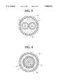
- FIG. 4is a cross-sectional view of an outer tube containing a coaxial cable
- FIG. 5is a cross-sectional view of a modification of the embodiment shown in FIG. 1 in which the water blocking material outside the tubes is replaced by a dry water swellable yarn or tape.
- FIG. 1is a cross-sectional view of a combination optical fiber cable 10 in accordance with one embodiment of the present invention, comprising a central tube 12 containing at least one optical fiber and a plurality of outer tubes 14, 16, 18 and 20 disposed around the central tube 12, each of which also contains at least one optical fiber.
- the tubes 12, 14, 16, 18 and 20can contain a single optical fiber, a plurality of separate optical fibers, an optical fiber ribbon, or an optical fiber bundle.
- a plurality of optical fiber ribbons 22are contained within the central tube 12, and a plurality of individual optical fibers 24 not bonded to each other, are contained within four outer tubes 14, 16, 18 and 20.
- the tubes 12, 14, 16, 18 and 20have inner diameters selected so that the cross-sectional area of the bores of the tubes are greater than the cross-sectional area of the optical fiber, plurality of fibers, or ribbons contained therein so that the optical fiber or fibers and ribbons are loosely contained, therein.
- a sheath 26surrounds the outer tubes.
- the fibers and ribbonsare of any known type, the ribbons comprising a planar array of fibers encapsulated in a plastic.
- any or all of the outer tubes 14, 16, 18 and 20can have inner diameters such that the cross-sectional area of the bores of the tubes are essentially the same as the cross-sectional area of the optical fiber, plurality of fibers, or ribbons contained therein, as well. Such a configuration is referred to as tight buffered fibers.
- At least two structural strength members 28are provided between the central tube 12 and the sheath 26, between the outer tubes 14, 16, 18 and 20.
- the structural strength members 28can be made of any high tensile modulus material, e.g., a non-metallic material, such as glass, epoxy rods, graphite yarns or a metallic material, such as stainless steel or carbon steel coated with copper or zinc to prevent corrosion.
- the coefficient of thermal expansion of the strength members 28is less than that of the central tube 12 and outer tubes 14, 16, 18 and 20 and the tensile modulus of the strength members is higher than the tensile modulus of such tubes.
- the structural strength members 28are shown covered by an optional covering 28a, such as polyethylene, for example, but the covering 28a can be omitted, particularly if the strength member is non-metallic.
- the diameter of the strength member 28is preferably no greater than that required to provide the desired protection. When the strength member 28 is metallic, the diameter of the strength member 28 is typically less than the diameter of the outer tubes 16.
- the thickness of the covering 28ais preferably about equal to the difference between the diameter of the strength member 28 and the diameter of the outer tube 16.
- the central tube 12preferably comprises a plastic material, such as high density polyethylene (“HDPE”).
- the outer tubes 14, 16, 18 and 20also preferably comprise a plastic material, such as polybutylene terephtalate (“PBT”) or HDPE.
- PBTpolybutylene terephtalate
- Other suitable plastic materials for the inner and outer tubesinclude polypropylene, polyvinylchloride and polymethylpentene.
- the plastic materials for the central and outer tubespreferably have a Young's Modulus in the range of from 20,000 to 500,000 psi.
- the central and outer tubescan also be metallic or composite materials, such as an epoxy mixed with glass fibers.
- the sheath 26, which is also, preferably, a plastic materialmay be medium density polyethylene (“MDPE”), for example.
- MDPEmedium density polyethylene
- two diametrically opposed longitudinal strength members 30extending substantially parallel to the axis of the cable 10 are embedded in the sheath 26.
- the longitudinal strength memberscan be steel, for example, as is known in the art.
- the longitudinal strength members 30 in the sheath 26protect the optical fibers from longitudinal stresses such as pulling during installation. If the cable 10 is intended to be used in applications which do not require pulling during installation, such as cables to be installed by the "blown-in" technique, strength members in the sheath may not be necessary.
- the strength members 30also allow bending of the cable perpendicular to the plane containing the two strength members 30.
- a water blocking material 32is provided within the central tube 12, within the outer tubes 14, 16, 18 and 20, and in the open spaces between the central tube 12, outer tubes 14, 16, 18 and 20 and the sheath 26.
- the water blocking material 32 within the outer tubes 14, 16, 18 and 20can be a thixotropic grease or gel, preferably with a viscosity at 20 seconds -1 in the range of from 8,000 to 25,000 cps. at 25° C.
- the water blocking material in the open spaces between the sheath 26 and the central tube 12, outside the outer tubes 14, 16, 18 and 20,is a thixotropic grease or gel having viscosity in the range of from 10 to 500 cps. at 125° C., in accordance with ASTM D-2699.
- the water blocking material preferred within the buffer tubes 14, 16, 18 and 20, discussed above,can be used in the open spaces outside of the tubes, as well.
- the materialcan contain small particles, preferably of a size less than about 500 microns, of a known water swellable material, such as sodium acrylate, to assist in preventing moisture from affecting the optical fibers.
- compounds for absorbing gas, such as hydrogenmay also be provided for assisting in protecting the optical fibers from deleterious gases.
- a known type of water swellable yarn 67can be stranded with the outer tubes 14, 16, 18 and 20 as shown in FIG. 5.
- a known type of water swellable tape 68can be wound around the outer tubes.
- a layer of corrugated steel armor 34is optionally provided around the outer tubes 14, 16, 18 and 20, and the tape 68, if present, adjacent to the inner surface of the sheath 26, to provide additional protection against crushing and rodents, for example.
- the armor 34can be of the type described in U.S. Pat. No. 5,509,097, which is incorporated by reference, herein.
- one or more ripcords 36 extending generally parallel to the axis of the cable 16are also provided adjacent the inner surface of the sheath 26 or the inner surface of the corrugated steel armor 34, if provided, to ease opening of the sheath 26, or the armor 34 and the sheath 26 when access to the tubes is required.
- Two ripcords 36are shown in FIGS. 1 and 5, although one or more than two can be included.
- the ripcordsmay be aramid, for example.
- the outer tubes 14, 16, 18 and 20 and strength members 28are engaged with the central tube 12, as shown in the perspective view of the combination cable 10 of the present invention in FIG. 2.
- the sheath 26 and the armor 34are partially removed.
- the outer tubes and the strength member 28are preferably wound in a reverse oscillating lay configuration.
- a cord 38 of polyester, nylon, aramid or fiberglass, for example,is preferably tied around the outer tubes 14, 16, 18 and 20 and strength members 28, to more tightly couple the outer tubes and strength members to each other and to the central tube 12.
- the cordcan be in the form of a monolithic fiber, a thread or a yarn.
- the cord 38applies radial inward forces to the structural strength members 28 and the outer tubes 14, 16, 18 and 20, maintaining the contact between the strength members, outer tubes and the central tube 12, to resist contraction or expansion of the tubes and buckling of the tubes caused by longitudinal forces on the tubes.
- the cord 38is preferably wound under tension, in the range of from about 200 grams to about 2,000 grams, for example. Preferably, the tension is in the range of from 600 to 1500 grams.
- the diameter of the cordis preferably less than about 2 mm. Its tensile strength at break is at least about 6,000 psi.
- a tapesuch as a commercially available polyester type with a tensile strength of about 6,000 psi, may be used.
- the tapemay have a thickness of about 0.020 mm to about 0.030 mm, and a width preferably less than about 1 inch, for example.
- the outer tubes and the strength membersare wound first in one direction around the central tube 12, and then wound in the opposite direction. Between the oppositely wound sections is a section "S" wherein the outer tubes 14, 16, 18 and 20 are parallel to each other and substantially parallel to the axis of the central tube 12. This is the preferred section for carrying out splices with the optical fiber in the outer tubes.
- winding the strength members 28 with the outer tubes 14, 16, 18 and 20provides better coupling between the strength members 28, the outer tubes 14, 16, 18 and 20 and the central tube 12, providing better resistance to thermal expansion and contraction of the outer tubes and the central tube. Binding the outer tubes and strength members to the central tube through a cord 38 further strengthens the coupling between the outer tubes, strength members and the central tube, further improving the resistance of the outer tubes and central tube to thermal expansion and contraction and to buckling.
- the combination optical fiber cable of the present inventioncan operate over a temperature range of from about -40° C. to about 70° C. and preferably, over a temperature range of about -50° C. to about 90° C.
- FIG. 3is a cross-sectional view of an outer tube 50, which can replace one of the tubes 14, 16, 18 and 20, containing a twisted pair of electrically conductive copper wires 52, each of which is surrounded by insulation 54.
- FIG. 4is a cross-sectional view of another outer tube 56, which can replace one of the tubes 14, 16, 18 and 20, containing a coaxial cable 58.
- a typical coaxial cableincludes an outer insulation layer 60, an outer conductor 62, an inner conductor 64 and insulation 66 between the outer and inner conductors 62, 64, as is known in the art. While water blocking material 32 can be included in the tubes 50 and 56, it can be omitted.
- the twisted copper pair 52 or coaxial cable 58need not be provided in a tube.
- the combination optical fiber cable of the present inventioncan be used wherever it is advantageous to provide a plurality of optical fibers to a plurality of locations.
- the cable of the present inventionis particularly suitable wherever it would be advantageous to provide express fibers for connecting relatively distant locations and enterable fibers for splicing to points between the distant locations, in the same cable.
- low speed loop fibersmay be desired along the same route as high speed interoffice links.
- the high speed interoffice linkscan be provided through an optical fiber ribbon in the central tube while the low speed loop fibers can be provided in the outer tubes.
- the optical fibers in the outer tubescan be easily accessed and spliced at Add/Drop remote terminal sites without disturbing the high-speed links.
- the combination optical fiber cable of the present inventionalso provides the flexibility to accommodate unanticipated or indefinite needs, such as those which typically arise in the construction of communities, particularly communities which may not have defined lot lines, or in areas of high potential growth.
- the optical fibers in the outer tubes of the cablecan be easily accessed for splicing, while the central tube remains sealed.
- Cables of the present inventionprovided along undeveloped rights of way are also readily available for fiber to the home (“FTTH”) applications. As development occurs, the new buildings can be spliced into the optical fibers of the outer tubes of the cable of the present invention.
- Pole mounted personal communications service (“PCS”) antennase.g., cellular optical sites
- PCSpersonal communications service
- antennasmay be required in locations which were not originally anticipated. If the cables of the present invention are servicing standard broadband or interoffice applications in the area through the central tube, the optical fibers in the outer tubes are available for splicing to future antenna nodes.
- the combination cable disclosedalso enables the separation of long distance and local service links for administrative or regulatory reasons such that long distance telephone service can be provided through the central tube while local service can be provided through the outer tubes. Broadcast and digital interactive services could similarly be separated.
Landscapes
- Physics & Mathematics (AREA)
- General Physics & Mathematics (AREA)
- Optics & Photonics (AREA)
- Light Guides In General And Applications Therefor (AREA)
- Communication Cables (AREA)
Abstract
Description
Claims (29)
Priority Applications (9)
| Application Number | Priority Date | Filing Date | Title |
|---|---|---|---|
| US08/897,921US5905834A (en) | 1997-07-21 | 1997-07-21 | Combination loose tube optical fiber cable with reverse oscillating lay |
| ES98305342TES2285750T3 (en) | 1997-07-21 | 1998-07-06 | COMBINED OPTICAL FIBER DWE CABLE. |
| EP98305342AEP0893722B1 (en) | 1997-07-21 | 1998-07-06 | Combination optical fiber cable |
| DE69837579TDE69837579T2 (en) | 1997-07-21 | 1998-07-06 | Fiber optic cable combination |
| JP10198878AJPH1195076A (en) | 1997-07-21 | 1998-07-14 | Fiber optic cable |
| NZ330969ANZ330969A (en) | 1997-07-21 | 1998-07-14 | Optical fibre cable, outer tubes including strength members wrapped around central tube |
| AU76289/98AAU728335B2 (en) | 1997-07-21 | 1998-07-16 | Combination optical fiber cable |
| ARP980103532AAR016365A1 (en) | 1997-07-21 | 1998-07-20 | AN OPTICAL FIBER CABLE. |
| BR9806521-1ABR9806521A (en) | 1997-07-21 | 1998-07-20 | Fiber optic cable |
Applications Claiming Priority (1)
| Application Number | Priority Date | Filing Date | Title |
|---|---|---|---|
| US08/897,921US5905834A (en) | 1997-07-21 | 1997-07-21 | Combination loose tube optical fiber cable with reverse oscillating lay |
Publications (1)
| Publication Number | Publication Date |
|---|---|
| US5905834Atrue US5905834A (en) | 1999-05-18 |
Family
ID=25408664
Family Applications (1)
| Application Number | Title | Priority Date | Filing Date |
|---|---|---|---|
| US08/897,921Expired - LifetimeUS5905834A (en) | 1997-07-21 | 1997-07-21 | Combination loose tube optical fiber cable with reverse oscillating lay |
Country Status (9)
| Country | Link |
|---|---|
| US (1) | US5905834A (en) |
| EP (1) | EP0893722B1 (en) |
| JP (1) | JPH1195076A (en) |
| AR (1) | AR016365A1 (en) |
| AU (1) | AU728335B2 (en) |
| BR (1) | BR9806521A (en) |
| DE (1) | DE69837579T2 (en) |
| ES (1) | ES2285750T3 (en) |
| NZ (1) | NZ330969A (en) |
Cited By (52)
| Publication number | Priority date | Publication date | Assignee | Title |
|---|---|---|---|---|
| US6049648A (en)* | 1998-08-26 | 2000-04-11 | Sumitomo Electric Lightwave Corp. | S-Z stranded optical cable with optimized short ROL pitch |
| US6377738B1 (en)* | 1998-12-04 | 2002-04-23 | Pirelli Cable Corporation | Optical fiber cable and core with a reinforced buffer tube having visible strength members and methods of manufacture thereof |
| US6445859B1 (en) | 2000-12-20 | 2002-09-03 | Alcatel | Central cavity cable with a predetermined gap that facilitates opening of the outer sheath |
| US6574400B1 (en)* | 1998-03-26 | 2003-06-03 | Corning Cable Systems Llc | Fiber optic cable with water blocking features |
| US6584251B1 (en) | 2000-05-23 | 2003-06-24 | Alcatel | Solid stranding flextube unit |
| US6597844B1 (en)* | 2000-12-29 | 2003-07-22 | Alcatel | Loose tube cable having an easily removable buffer tube binder for cable access |
| US6714709B1 (en)* | 1999-05-19 | 2004-03-30 | Alcatel | Optical submarine cable |
| US6748146B2 (en) | 1999-05-28 | 2004-06-08 | Corning Cable Systems Llc | Communication cable having a soft housing |
| US20040240806A1 (en)* | 2003-05-30 | 2004-12-02 | Lail Jason C. | Fiber optic cable having a binder |
| US6841729B2 (en)* | 2000-10-13 | 2005-01-11 | Sumitomo Electric Industries, Ltd. | Self-supporting cable and manufacturing method therefor |
| US6987916B2 (en)* | 2001-12-18 | 2006-01-17 | Alcatel | Fiber optic central tube cable with bundled support member |
| US7006740B1 (en) | 1999-05-28 | 2006-02-28 | Corning Cable Systems, Llc | Communication cable having a soft housing |
| US20060151040A1 (en)* | 2002-11-18 | 2006-07-13 | Olsen Soren B | Hoselike member having a circumference which is composed of a number of metal wires or tubes |
| US20060245700A1 (en)* | 2003-07-17 | 2006-11-02 | Draka Comteq B.V. | Groove cable |
| WO2007021673A3 (en)* | 2005-08-12 | 2007-06-28 | Afl Telecommunications Llc | Tapered cable for use in fiber to the premises applications |
| US20080240662A1 (en)* | 2007-03-16 | 2008-10-02 | Real Helvenstein | Optical cable for connection to a general distribution network, and a method of connecting said cable |
| US20090169159A1 (en)* | 2007-12-31 | 2009-07-02 | David Keller | Flat wide water swellable binder for optical fiber tubes |
| US20090214167A1 (en)* | 2008-02-25 | 2009-08-27 | Draka Comteq B.V. | Optical Cable Buffer Tube with Integrated Hollow Channels |
| US20090252463A1 (en)* | 2008-04-04 | 2009-10-08 | Baker Hughes Incorporated | Rtci cable and method |
| US20100104247A1 (en)* | 2007-03-12 | 2010-04-29 | Sumitomo Electric Industries, Ltd. | Optical access network system |
| US20110058778A1 (en)* | 2009-05-08 | 2011-03-10 | Brian Herbst | Cable including strain-free fiber and strain-coupled fiber |
| WO2011060518A1 (en)* | 2009-11-21 | 2011-05-26 | Rfs Brasil Telecomunicações Ltda | Hybrid pigtail for mobile telecommunications |
| US20110188809A1 (en)* | 2010-02-02 | 2011-08-04 | Adc Telecommunications, Inc. | Fiber optic cable bundle with staggered connectors |
| US20110211793A1 (en)* | 2008-10-09 | 2011-09-01 | Barrett Louis A | Optical fiber assemblies |
| US20110317968A1 (en)* | 2010-06-29 | 2011-12-29 | Cline Timothy S | Fiber optic cable furcation methods and assemblies |
| US20120125596A1 (en)* | 2010-11-24 | 2012-05-24 | Baker Hughes Incorporated | Ruggedized fiber optic cable and method of optical fiber transmission |
| US8452142B1 (en)* | 2010-08-20 | 2013-05-28 | Superior Essex Communications Lp | Railway deployable composite communication cable |
| US20130247576A1 (en)* | 2012-03-23 | 2013-09-26 | Delavan Inc | Apparatus, system and method for observing combustor flames in a gas turbine engine |
| US20130336612A1 (en)* | 2011-03-09 | 2013-12-19 | Jeremiah Glen Pearce | Integrated fiber optic monitoring system for a wellsite and method of using same |
| EP2399155A4 (en)* | 2009-02-17 | 2014-07-09 | Foro Energy Inc | OPTICAL FIBER CABLE FOR TRANSMISSION OF HIGH POWER LASER ENERGY OVER GREAT DISTANCES |
| US8805151B2 (en) | 2010-05-19 | 2014-08-12 | Adc Telecommunications, Inc. | Lashing together multiple fiber optic telecommunications cables |
| US20140236125A1 (en)* | 2013-02-15 | 2014-08-21 | Hitachi Cable, Ltd. | Catheter wire |
| US9089928B2 (en) | 2008-08-20 | 2015-07-28 | Foro Energy, Inc. | Laser systems and methods for the removal of structures |
| US20150338591A1 (en)* | 2012-03-07 | 2015-11-26 | Celerity Technologies Inc. | Fiber optic cable with electrical connectors at both ends |
| US20150355430A1 (en)* | 2014-06-10 | 2015-12-10 | Corning Optical Communications LLC | Fiber optic cable structured to facilitate accessing an end thereof |
| US20160356974A1 (en)* | 2015-06-03 | 2016-12-08 | Corning Optical Communications LLC | Optical fiber cable with bonded core elements |
| US9627100B2 (en)* | 2013-04-24 | 2017-04-18 | Wireco World Group Inc. | High-power low-resistance electromechanical cable |
| US9664012B2 (en) | 2008-08-20 | 2017-05-30 | Foro Energy, Inc. | High power laser decomissioning of multistring and damaged wells |
| US20170153403A1 (en)* | 2015-11-30 | 2017-06-01 | Corning Optical Communications LLC | Fiber-bundle assembly for maintaining a select order in an optical fiber cable |
| WO2017160666A1 (en) | 2016-03-15 | 2017-09-21 | Commscope, Inc. Of North Carolina | Multi-member cable with improved mid-span access |
| US20170343433A1 (en)* | 2009-11-13 | 2017-11-30 | Optasense Holdings Limited | Optic Fibres and Fibre Optic Sensing |
| WO2018226896A1 (en) | 2017-06-09 | 2018-12-13 | Commscope Technologies Llc | Disintegrating binders for multi-member cable |
| WO2019143144A1 (en)* | 2018-01-19 | 2019-07-25 | 엘에스전선 주식회사 | Optical cable |
| US11079553B2 (en) | 2019-08-22 | 2021-08-03 | Cotsworks, Llc | Field installable rugged optical terminus |
| US20220206238A1 (en)* | 2020-12-31 | 2022-06-30 | Prysmian S.P.A. | Multisensing Optical Fiber Cable |
| US20230194813A1 (en)* | 2020-05-15 | 2023-06-22 | Afl Telecommunications Llc | Indoor/outdoor micro-duct cables |
| WO2024015202A1 (en)* | 2022-07-14 | 2024-01-18 | Commscope Technologies Llc | Optimized low fiber count stranded loose tube fiber cable |
| US20240219661A1 (en)* | 2013-06-14 | 2024-07-04 | Chiral Photonics, Inc. | Multichannel optical coupler array |
| EP4211505A4 (en)* | 2020-09-14 | 2024-09-25 | Corning Research & Development Corporation | Bundled drop assembly having increased stiffness and subunit layers with unidirectional winding |
| EP4468048A1 (en)* | 2023-05-25 | 2024-11-27 | Sterlite Technologies Limited | Optical fiber cable with bundles of optical fibers |
| EP4524632A1 (en)* | 2023-09-15 | 2025-03-19 | HFCL Limited | Compact armored intermittently bonded ribbon cables |
| EP4524634A1 (en)* | 2023-09-15 | 2025-03-19 | HFCL Limited | Compact armored intermittently bonded ribbon cables |
Families Citing this family (12)
| Publication number | Priority date | Publication date | Assignee | Title |
|---|---|---|---|---|
| DE19813444A1 (en)* | 1998-03-26 | 1999-09-30 | Cit Alcatel | Hybrid cable with optical fiber and electrical conductor |
| NL1011054C2 (en)* | 1999-01-18 | 2000-07-19 | Ebcon Materials Nv | Modular cable and modular fiber access system. |
| US6621966B2 (en)* | 1999-03-31 | 2003-09-16 | Corning Cable Systems Llc | Fiber optic cable with profiled group of optical fibers |
| BR0012188A (en) | 1999-06-30 | 2002-04-30 | Moo Won Byun | Multiple channel cable duct set |
| US6563991B1 (en)* | 2000-06-13 | 2003-05-13 | Alcatel | Optical fiber cable for easy access to ripcords and having ripcord reliability |
| NO20032119D0 (en)* | 2003-05-12 | 2003-05-12 | Nexans | Monitoring Cable |
| DE102004037589A1 (en)* | 2004-08-03 | 2006-03-16 | CCS Technology, Inc., Wilmington | Optical cable and method of making an optical cable |
| EP2431779A1 (en)* | 2010-09-16 | 2012-03-21 | GM Plast A/S | Tube assembly for guiding and protecting optical fibre cables |
| CN104900319A (en)* | 2015-06-28 | 2015-09-09 | 黄浩 | Central tube type cable with improved structure |
| JP6676032B2 (en) | 2017-12-21 | 2020-04-08 | 株式会社フジクラ | Fiber optic cable |
| CN108761688A (en)* | 2018-06-26 | 2018-11-06 | 江苏亨通光电股份有限公司 | A kind of miniature flexible armouring direct-burried, pipeline optical cable and optical cable production technology |
| JP7182509B2 (en)* | 2019-04-25 | 2022-12-02 | 株式会社フジクラ | fiber optic cable |
Citations (20)
| Publication number | Priority date | Publication date | Assignee | Title |
|---|---|---|---|---|
| US4078853A (en)* | 1976-02-25 | 1978-03-14 | Bell Telephone Laboratories, Incorporated | Optical communication cable |
| DE2854746A1 (en)* | 1977-12-21 | 1979-06-28 | Bicc Ltd | OPTICAL CABLE |
| US4230395A (en)* | 1975-02-05 | 1980-10-28 | Bicc Limited | Optical cables with loosely housed optical guides |
| US4688888A (en)* | 1983-05-28 | 1987-08-25 | Alcatel N.V. | Optical cable |
| US4720164A (en)* | 1984-07-05 | 1988-01-19 | Siemens Aktiengesellschaft | Pressure-tight optical cable |
| US4822132A (en)* | 1987-03-02 | 1989-04-18 | Siemens Aktiengesellschaft | Optical communications cable |
| GB2215081A (en)* | 1988-02-11 | 1989-09-13 | Stc Plc | Optical fibre cable |
| DE9003135U1 (en)* | 1990-03-17 | 1990-06-07 | kabelmetal electro GmbH, 3000 Hannover | Electrical or optical cable with tear threads |
| EP0438684A2 (en)* | 1990-01-22 | 1991-07-31 | Alcatel N.V. | Unitube optical fiber cable |
| US5247599A (en)* | 1992-06-05 | 1993-09-21 | Sumitomo Electric Fiber Optics Corp. | Steam resistant optical fiber cable |
| US5325457A (en)* | 1991-09-20 | 1994-06-28 | Bottoms Jack Jr | Field protected self-supporting fiber optic cable |
| US5329606A (en)* | 1992-02-06 | 1994-07-12 | Alcatel Kabel Norge As | Fiber optic cable |
| US5343549A (en)* | 1993-08-25 | 1994-08-30 | Siecor Corporation | Riser optical cable having filling compound |
| US5384880A (en)* | 1993-12-03 | 1995-01-24 | Alcatel Na Cable Systems, Inc. | Dielectric ribbon optical fiber cable |
| US5448669A (en)* | 1992-03-24 | 1995-09-05 | At&T Corp. | Hybrid communications cable for enhancement of transmission capability |
| US5463711A (en)* | 1994-07-29 | 1995-10-31 | At&T Ipm Corp. | Submarine cable having a centrally located tube containing optical fibers |
| DE29520915U1 (en)* | 1995-03-04 | 1996-05-02 | Alcatel Kabel AG & Co., 30179 Hannover | Communication cable |
| US5531064A (en)* | 1994-06-03 | 1996-07-02 | Fujikura Ltd. | Optical fiber cable containing ribbon fibers |
| US5542020A (en)* | 1994-06-10 | 1996-07-30 | Commscope, Inc. | Fiber optic cable having extended contraction window and associated method and apparatus for fabricating the cable |
| EP0853249A1 (en)* | 1997-01-10 | 1998-07-15 | Lucent Technologies Inc. | Composite fiber optic distribution cable |
Family Cites Families (1)
| Publication number | Priority date | Publication date | Assignee | Title |
|---|---|---|---|---|
| US5509097A (en)* | 1994-04-07 | 1996-04-16 | Pirelli Cable Corporation | Optical fiber core and cable with reinforced buffer tube loosely enclosing optical fibers |
- 1997
- 1997-07-21USUS08/897,921patent/US5905834A/ennot_activeExpired - Lifetime
- 1998
- 1998-07-06ESES98305342Tpatent/ES2285750T3/ennot_activeExpired - Lifetime
- 1998-07-06DEDE69837579Tpatent/DE69837579T2/ennot_activeExpired - Lifetime
- 1998-07-06EPEP98305342Apatent/EP0893722B1/ennot_activeExpired - Lifetime
- 1998-07-14JPJP10198878Apatent/JPH1195076A/enactivePending
- 1998-07-14NZNZ330969Apatent/NZ330969A/ennot_activeIP Right Cessation
- 1998-07-16AUAU76289/98Apatent/AU728335B2/ennot_activeCeased
- 1998-07-20BRBR9806521-1Apatent/BR9806521A/ennot_activeApplication Discontinuation
- 1998-07-20ARARP980103532Apatent/AR016365A1/enactiveIP Right Grant
Patent Citations (21)
| Publication number | Priority date | Publication date | Assignee | Title |
|---|---|---|---|---|
| US4230395A (en)* | 1975-02-05 | 1980-10-28 | Bicc Limited | Optical cables with loosely housed optical guides |
| US4078853A (en)* | 1976-02-25 | 1978-03-14 | Bell Telephone Laboratories, Incorporated | Optical communication cable |
| DE2854746A1 (en)* | 1977-12-21 | 1979-06-28 | Bicc Ltd | OPTICAL CABLE |
| US4272155A (en)* | 1977-12-21 | 1981-06-09 | Bicc Limited | Optical cables |
| US4688888A (en)* | 1983-05-28 | 1987-08-25 | Alcatel N.V. | Optical cable |
| US4720164A (en)* | 1984-07-05 | 1988-01-19 | Siemens Aktiengesellschaft | Pressure-tight optical cable |
| US4822132A (en)* | 1987-03-02 | 1989-04-18 | Siemens Aktiengesellschaft | Optical communications cable |
| GB2215081A (en)* | 1988-02-11 | 1989-09-13 | Stc Plc | Optical fibre cable |
| EP0438684A2 (en)* | 1990-01-22 | 1991-07-31 | Alcatel N.V. | Unitube optical fiber cable |
| DE9003135U1 (en)* | 1990-03-17 | 1990-06-07 | kabelmetal electro GmbH, 3000 Hannover | Electrical or optical cable with tear threads |
| US5325457A (en)* | 1991-09-20 | 1994-06-28 | Bottoms Jack Jr | Field protected self-supporting fiber optic cable |
| US5329606A (en)* | 1992-02-06 | 1994-07-12 | Alcatel Kabel Norge As | Fiber optic cable |
| US5448669A (en)* | 1992-03-24 | 1995-09-05 | At&T Corp. | Hybrid communications cable for enhancement of transmission capability |
| US5247599A (en)* | 1992-06-05 | 1993-09-21 | Sumitomo Electric Fiber Optics Corp. | Steam resistant optical fiber cable |
| US5343549A (en)* | 1993-08-25 | 1994-08-30 | Siecor Corporation | Riser optical cable having filling compound |
| US5384880A (en)* | 1993-12-03 | 1995-01-24 | Alcatel Na Cable Systems, Inc. | Dielectric ribbon optical fiber cable |
| US5531064A (en)* | 1994-06-03 | 1996-07-02 | Fujikura Ltd. | Optical fiber cable containing ribbon fibers |
| US5542020A (en)* | 1994-06-10 | 1996-07-30 | Commscope, Inc. | Fiber optic cable having extended contraction window and associated method and apparatus for fabricating the cable |
| US5463711A (en)* | 1994-07-29 | 1995-10-31 | At&T Ipm Corp. | Submarine cable having a centrally located tube containing optical fibers |
| DE29520915U1 (en)* | 1995-03-04 | 1996-05-02 | Alcatel Kabel AG & Co., 30179 Hannover | Communication cable |
| EP0853249A1 (en)* | 1997-01-10 | 1998-07-15 | Lucent Technologies Inc. | Composite fiber optic distribution cable |
Cited By (85)
| Publication number | Priority date | Publication date | Assignee | Title |
|---|---|---|---|---|
| US6574400B1 (en)* | 1998-03-26 | 2003-06-03 | Corning Cable Systems Llc | Fiber optic cable with water blocking features |
| US6049648A (en)* | 1998-08-26 | 2000-04-11 | Sumitomo Electric Lightwave Corp. | S-Z stranded optical cable with optimized short ROL pitch |
| US6377738B1 (en)* | 1998-12-04 | 2002-04-23 | Pirelli Cable Corporation | Optical fiber cable and core with a reinforced buffer tube having visible strength members and methods of manufacture thereof |
| US6546176B2 (en)* | 1998-12-04 | 2003-04-08 | Pirelli Cable Corporation | Optical fiber cable and core with a reinforced buffer tube having visible strength members and methods of manufacture thereof |
| US6714709B1 (en)* | 1999-05-19 | 2004-03-30 | Alcatel | Optical submarine cable |
| US6748146B2 (en) | 1999-05-28 | 2004-06-08 | Corning Cable Systems Llc | Communication cable having a soft housing |
| US7006740B1 (en) | 1999-05-28 | 2006-02-28 | Corning Cable Systems, Llc | Communication cable having a soft housing |
| US20030202758A1 (en)* | 2000-05-23 | 2003-10-30 | Alcatel | Method and apparatus for solid-stranding a flextube unit |
| US6584251B1 (en) | 2000-05-23 | 2003-06-24 | Alcatel | Solid stranding flextube unit |
| US7192541B2 (en) | 2000-05-23 | 2007-03-20 | Draka Comteo B.V. | Method and apparatus for solid-stranding a flextube unit |
| US6841729B2 (en)* | 2000-10-13 | 2005-01-11 | Sumitomo Electric Industries, Ltd. | Self-supporting cable and manufacturing method therefor |
| US6445859B1 (en) | 2000-12-20 | 2002-09-03 | Alcatel | Central cavity cable with a predetermined gap that facilitates opening of the outer sheath |
| US6597844B1 (en)* | 2000-12-29 | 2003-07-22 | Alcatel | Loose tube cable having an easily removable buffer tube binder for cable access |
| US6987916B2 (en)* | 2001-12-18 | 2006-01-17 | Alcatel | Fiber optic central tube cable with bundled support member |
| US20060151040A1 (en)* | 2002-11-18 | 2006-07-13 | Olsen Soren B | Hoselike member having a circumference which is composed of a number of metal wires or tubes |
| US7849885B2 (en)* | 2002-11-18 | 2010-12-14 | Norsk Hydro Asa | Hose member |
| WO2004109356A1 (en)* | 2003-05-30 | 2004-12-16 | Corning Cable Systems Llc | Fiber optic cable having a binder |
| US20040240806A1 (en)* | 2003-05-30 | 2004-12-02 | Lail Jason C. | Fiber optic cable having a binder |
| US20060245700A1 (en)* | 2003-07-17 | 2006-11-02 | Draka Comteq B.V. | Groove cable |
| US7197216B2 (en)* | 2003-07-17 | 2007-03-27 | Draka Comteq B.V. | Groove cable having a predetermined longitudinal thermal expansion force |
| US20080193091A1 (en)* | 2005-08-12 | 2008-08-14 | Afl Telecommunications Llc | Tapered Cable For Use In Fiber To The Premises Applications |
| US7590320B2 (en) | 2005-08-12 | 2009-09-15 | Afl Telecommunications Llc | Tapered cable for use in fiber to the premises applications |
| WO2007021673A3 (en)* | 2005-08-12 | 2007-06-28 | Afl Telecommunications Llc | Tapered cable for use in fiber to the premises applications |
| US20100104247A1 (en)* | 2007-03-12 | 2010-04-29 | Sumitomo Electric Industries, Ltd. | Optical access network system |
| US20080240662A1 (en)* | 2007-03-16 | 2008-10-02 | Real Helvenstein | Optical cable for connection to a general distribution network, and a method of connecting said cable |
| US20090169159A1 (en)* | 2007-12-31 | 2009-07-02 | David Keller | Flat wide water swellable binder for optical fiber tubes |
| US7570854B2 (en)* | 2007-12-31 | 2009-08-04 | Nexans | Flat wide water swellable binder for optical fiber tubes |
| US20090214167A1 (en)* | 2008-02-25 | 2009-08-27 | Draka Comteq B.V. | Optical Cable Buffer Tube with Integrated Hollow Channels |
| US8326103B2 (en)* | 2008-04-04 | 2012-12-04 | Baker Hughes Incorporated | Cable and method |
| US20090252463A1 (en)* | 2008-04-04 | 2009-10-08 | Baker Hughes Incorporated | Rtci cable and method |
| US20130051739A1 (en)* | 2008-04-04 | 2013-02-28 | Carl Stoesz | Fiber deployment assembly and method |
| US9664012B2 (en) | 2008-08-20 | 2017-05-30 | Foro Energy, Inc. | High power laser decomissioning of multistring and damaged wells |
| US9089928B2 (en) | 2008-08-20 | 2015-07-28 | Foro Energy, Inc. | Laser systems and methods for the removal of structures |
| US20110211793A1 (en)* | 2008-10-09 | 2011-09-01 | Barrett Louis A | Optical fiber assemblies |
| US8731352B2 (en) | 2008-10-09 | 2014-05-20 | Corning Cable Systems Llc | Optical fiber assemblies |
| US8983254B2 (en) | 2008-10-09 | 2015-03-17 | Corning Cable Systems Llc | Optical fiber assemblies |
| US8565565B2 (en) | 2008-10-09 | 2013-10-22 | Corning Cable Systems Llc | Optical fiber assemblies |
| US9347271B2 (en) | 2008-10-17 | 2016-05-24 | Foro Energy, Inc. | Optical fiber cable for transmission of high power laser energy over great distances |
| EP2399155A4 (en)* | 2009-02-17 | 2014-07-09 | Foro Energy Inc | OPTICAL FIBER CABLE FOR TRANSMISSION OF HIGH POWER LASER ENERGY OVER GREAT DISTANCES |
| US20110058778A1 (en)* | 2009-05-08 | 2011-03-10 | Brian Herbst | Cable including strain-free fiber and strain-coupled fiber |
| US20170343433A1 (en)* | 2009-11-13 | 2017-11-30 | Optasense Holdings Limited | Optic Fibres and Fibre Optic Sensing |
| US11099085B2 (en)* | 2009-11-13 | 2021-08-24 | Optasense Holdings Limited | Optic fibres and fibre optic sensing |
| WO2011060518A1 (en)* | 2009-11-21 | 2011-05-26 | Rfs Brasil Telecomunicações Ltda | Hybrid pigtail for mobile telecommunications |
| EP2531877A4 (en)* | 2010-02-02 | 2013-12-04 | Adc Telecommunications Inc | OPTICAL FIBER CABLE BEAM HAVING QUINCONCE CONNECTORS |
| US20110188809A1 (en)* | 2010-02-02 | 2011-08-04 | Adc Telecommunications, Inc. | Fiber optic cable bundle with staggered connectors |
| US8801296B2 (en) | 2010-02-02 | 2014-08-12 | Adc Telecommunications, Inc. | Fiber optic cable bundle with staggered connectors |
| US8805151B2 (en) | 2010-05-19 | 2014-08-12 | Adc Telecommunications, Inc. | Lashing together multiple fiber optic telecommunications cables |
| CN102375191B (en)* | 2010-06-29 | 2015-04-15 | 康宁光缆系统有限责任公司 | Fiber optic cable furcation methods and assemblies |
| US20110317968A1 (en)* | 2010-06-29 | 2011-12-29 | Cline Timothy S | Fiber optic cable furcation methods and assemblies |
| CN102375191A (en)* | 2010-06-29 | 2012-03-14 | 康宁光缆系统有限责任公司 | Fiber optic cable furcation methods and assemblies |
| US8380029B2 (en)* | 2010-06-29 | 2013-02-19 | Corning Cable Systems Llc | Fiber optic cable furcation methods and assemblies |
| US9116320B1 (en)* | 2010-08-20 | 2015-08-25 | Superior Essex International LP | Railway deployable composite communication cable |
| US8452142B1 (en)* | 2010-08-20 | 2013-05-28 | Superior Essex Communications Lp | Railway deployable composite communication cable |
| US20120125596A1 (en)* | 2010-11-24 | 2012-05-24 | Baker Hughes Incorporated | Ruggedized fiber optic cable and method of optical fiber transmission |
| US20130336612A1 (en)* | 2011-03-09 | 2013-12-19 | Jeremiah Glen Pearce | Integrated fiber optic monitoring system for a wellsite and method of using same |
| US9074462B2 (en)* | 2011-03-09 | 2015-07-07 | Shell Oil Company | Integrated fiber optic monitoring system for a wellsite and method of using same |
| US20150338591A1 (en)* | 2012-03-07 | 2015-11-26 | Celerity Technologies Inc. | Fiber optic cable with electrical connectors at both ends |
| US20130247576A1 (en)* | 2012-03-23 | 2013-09-26 | Delavan Inc | Apparatus, system and method for observing combustor flames in a gas turbine engine |
| US8937253B2 (en)* | 2013-02-15 | 2015-01-20 | Hitachi Metals, Ltd. | Catheter wire |
| US20140236125A1 (en)* | 2013-02-15 | 2014-08-21 | Hitachi Cable, Ltd. | Catheter wire |
| US10199140B2 (en) | 2013-04-24 | 2019-02-05 | Wireco Worldgroup Inc. | High-power low-resistance electromechanical cable |
| US9627100B2 (en)* | 2013-04-24 | 2017-04-18 | Wireco World Group Inc. | High-power low-resistance electromechanical cable |
| US20240219661A1 (en)* | 2013-06-14 | 2024-07-04 | Chiral Photonics, Inc. | Multichannel optical coupler array |
| US10126517B2 (en)* | 2014-06-10 | 2018-11-13 | Corning Optical Communications LLC | Fiber optic cable structured to facilitate accessing an end thereof |
| US20150355430A1 (en)* | 2014-06-10 | 2015-12-10 | Corning Optical Communications LLC | Fiber optic cable structured to facilitate accessing an end thereof |
| AU2015275016B2 (en)* | 2014-06-10 | 2019-09-12 | Corning Optical Communications LLC | Fiber optic cable structured to facilitate accessing an end thereof |
| US9977207B2 (en)* | 2015-06-03 | 2018-05-22 | Corning Optical Communications LLC | Optical fiber cable with bonded core elements |
| US20160356974A1 (en)* | 2015-06-03 | 2016-12-08 | Corning Optical Communications LLC | Optical fiber cable with bonded core elements |
| US10317635B2 (en) | 2015-06-03 | 2019-06-11 | Corning Optical Communications LLC | Optical fiber cable with bonded core elements |
| US20170153403A1 (en)* | 2015-11-30 | 2017-06-01 | Corning Optical Communications LLC | Fiber-bundle assembly for maintaining a select order in an optical fiber cable |
| US9746629B2 (en)* | 2015-11-30 | 2017-08-29 | Corning Optical Communications LLC | Fiber-bundle assembly for maintaining a select order in an optical fiber cable |
| WO2017160666A1 (en) | 2016-03-15 | 2017-09-21 | Commscope, Inc. Of North Carolina | Multi-member cable with improved mid-span access |
| US10600533B2 (en) | 2016-03-15 | 2020-03-24 | Commscope, Inc. Of North Carolina | Multi-member cable with improved mid-span access |
| WO2018226896A1 (en) | 2017-06-09 | 2018-12-13 | Commscope Technologies Llc | Disintegrating binders for multi-member cable |
| US11095103B2 (en) | 2017-06-09 | 2021-08-17 | Commscope Technologies Llc | Disintegrating binders for multi-member cable |
| WO2019143144A1 (en)* | 2018-01-19 | 2019-07-25 | 엘에스전선 주식회사 | Optical cable |
| US11079553B2 (en) | 2019-08-22 | 2021-08-03 | Cotsworks, Llc | Field installable rugged optical terminus |
| US20230194813A1 (en)* | 2020-05-15 | 2023-06-22 | Afl Telecommunications Llc | Indoor/outdoor micro-duct cables |
| EP4211505A4 (en)* | 2020-09-14 | 2024-09-25 | Corning Research & Development Corporation | Bundled drop assembly having increased stiffness and subunit layers with unidirectional winding |
| US11714245B2 (en)* | 2020-12-31 | 2023-08-01 | Prysmian S.P.A. | Multisensing optical fiber cable |
| US20220206238A1 (en)* | 2020-12-31 | 2022-06-30 | Prysmian S.P.A. | Multisensing Optical Fiber Cable |
| WO2024015202A1 (en)* | 2022-07-14 | 2024-01-18 | Commscope Technologies Llc | Optimized low fiber count stranded loose tube fiber cable |
| EP4468048A1 (en)* | 2023-05-25 | 2024-11-27 | Sterlite Technologies Limited | Optical fiber cable with bundles of optical fibers |
| EP4524632A1 (en)* | 2023-09-15 | 2025-03-19 | HFCL Limited | Compact armored intermittently bonded ribbon cables |
| EP4524634A1 (en)* | 2023-09-15 | 2025-03-19 | HFCL Limited | Compact armored intermittently bonded ribbon cables |
Also Published As
| Publication number | Publication date |
|---|---|
| AR016365A1 (en) | 2001-07-04 |
| JPH1195076A (en) | 1999-04-09 |
| NZ330969A (en) | 1999-04-29 |
| AU7628998A (en) | 1999-01-28 |
| ES2285750T3 (en) | 2007-11-16 |
| BR9806521A (en) | 2001-03-20 |
| EP0893722B1 (en) | 2007-04-18 |
| EP0893722A1 (en) | 1999-01-27 |
| AU728335B2 (en) | 2001-01-04 |
| DE69837579T2 (en) | 2008-01-03 |
| DE69837579D1 (en) | 2007-05-31 |
Similar Documents
| Publication | Publication Date | Title |
|---|---|---|
| US5905834A (en) | Combination loose tube optical fiber cable with reverse oscillating lay | |
| CA2242707C (en) | Combination optical fiber cable | |
| US5050957A (en) | Optical fiber service cable | |
| EP0969302B1 (en) | Composite cable for access networks | |
| US5740295A (en) | Low fiber count optical cable | |
| US4730894A (en) | Optical fiber cable having a prefabricated strength system and methods of making | |
| US5673352A (en) | Fiber optic micro cable | |
| US5229851A (en) | Optical fiber cable with large number of ribbon units containing optical fibers and enclosed in tubes | |
| US5325457A (en) | Field protected self-supporting fiber optic cable | |
| EP1591814B1 (en) | High count optical fiber cable | |
| EP0562770B1 (en) | Hybrid communications cable for enhancement of transmission capability | |
| US5913003A (en) | Composite fiber optic distribution cable | |
| CA2359753C (en) | Optical fiber cable with support member for indoor and outdoor use | |
| EP1969408B1 (en) | All-dielectric self-supporting cable having high fiber count | |
| EP1070975A1 (en) | Optical fiber cable with single strength member in cable outer jacket | |
| WO1997030369A1 (en) | Fiber optic ground wire cable | |
| US6349161B1 (en) | Undersea communications cable having centrally located, plastic buffer tube | |
| CA2315605A1 (en) | Composite fiber optic/coaxial electrical cables | |
| US6421487B1 (en) | Reinforced buffered fiber optic ribbon cable | |
| EP0498621A2 (en) | Fiber optic groundwire cable | |
| US5230034A (en) | All dielectric self-supporting fiber optic cable | |
| US20190113703A1 (en) | Fiber Optic Drop Cable | |
| US12431262B2 (en) | Hybrid drop cable | |
| US20250093605A1 (en) | Compact armored intermittently bonded ribbon cables | |
| Galliano | Optical Fiber Cables |
Legal Events
| Date | Code | Title | Description |
|---|---|---|---|
| AS | Assignment | Owner name:PIRELLI CABLE CORPORATION, SOUTH CAROLINA Free format text:ASSIGNMENT OF ASSIGNORS INTEREST;ASSIGNORS:ANDERSON, AARON M.;SMITH, JOHN C.;REEL/FRAME:008648/0979 Effective date:19970718 | |
| STCF | Information on status: patent grant | Free format text:PATENTED CASE | |
| FPAY | Fee payment | Year of fee payment:4 | |
| FPAY | Fee payment | Year of fee payment:8 | |
| AS | Assignment | Owner name:PRYSMIAN COMMUNICATIONS CABLES AND SYSTEMS USA, LL Free format text:CHANGE OF NAME;ASSIGNOR:PIRELLI COMMUNICATIONS CABLES AND SYSTEMS USA, LLC;REEL/FRAME:018802/0369 Effective date:20050921 Owner name:PIRELLI CABLES AND SYSTEMS LLC, SOUTH CAROLINA Free format text:MERGER;ASSIGNORS:PIRELLI CABLE CORPORATION;PIRELLI CABLES AND SYSTEMS LLC;REEL/FRAME:018802/0191 Effective date:19971231 Owner name:PIRELLI COMMUNICATIONS CABLES AND SYSTEMS USA, LLC Free format text:CHANGE OF NAME;ASSIGNOR:PIRELLI CABLES AND SYSTEMS LLC;REEL/FRAME:018802/0218 Effective date:20010601 | |
| FPAY | Fee payment | Year of fee payment:12 |