US5905819A - Method and apparatus for hiding one image or pattern within another - Google Patents
Method and apparatus for hiding one image or pattern within anotherDownload PDFInfo
- Publication number
- US5905819A US5905819AUS08/596,818US59681896AUS5905819AUS 5905819 AUS5905819 AUS 5905819AUS 59681896 AUS59681896 AUS 59681896AUS 5905819 AUS5905819 AUS 5905819A
- Authority
- US
- United States
- Prior art keywords
- image
- images
- modified
- produce
- modifying
- Prior art date
- Legal status (The legal status is an assumption and is not a legal conclusion. Google has not performed a legal analysis and makes no representation as to the accuracy of the status listed.)
- Expired - Lifetime
Links
Images


Classifications
- G—PHYSICS
- G06—COMPUTING OR CALCULATING; COUNTING
- G06T—IMAGE DATA PROCESSING OR GENERATION, IN GENERAL
- G06T1/00—General purpose image data processing
- G06T1/0021—Image watermarking
- G06T1/0028—Adaptive watermarking, e.g. Human Visual System [HVS]-based watermarking
- H—ELECTRICITY
- H04—ELECTRIC COMMUNICATION TECHNIQUE
- H04N—PICTORIAL COMMUNICATION, e.g. TELEVISION
- H04N1/00—Scanning, transmission or reproduction of documents or the like, e.g. facsimile transmission; Details thereof
- H04N1/32—Circuits or arrangements for control or supervision between transmitter and receiver or between image input and image output device, e.g. between a still-image camera and its memory or between a still-image camera and a printer device
- H04N1/32101—Display, printing, storage or transmission of additional information, e.g. ID code, date and time or title
- H04N1/32144—Display, printing, storage or transmission of additional information, e.g. ID code, date and time or title embedded in the image data, i.e. enclosed or integrated in the image, e.g. watermark, super-imposed logo or stamp
- H04N1/32149—Methods relating to embedding, encoding, decoding, detection or retrieval operations
- H04N1/32203—Spatial or amplitude domain methods
- H04N1/32208—Spatial or amplitude domain methods involving changing the magnitude of selected pixels, e.g. overlay of information or super-imposition
- H—ELECTRICITY
- H04—ELECTRIC COMMUNICATION TECHNIQUE
- H04N—PICTORIAL COMMUNICATION, e.g. TELEVISION
- H04N1/00—Scanning, transmission or reproduction of documents or the like, e.g. facsimile transmission; Details thereof
- H04N1/32—Circuits or arrangements for control or supervision between transmitter and receiver or between image input and image output device, e.g. between a still-image camera and its memory or between a still-image camera and a printer device
- H04N1/32101—Display, printing, storage or transmission of additional information, e.g. ID code, date and time or title
- H04N1/32144—Display, printing, storage or transmission of additional information, e.g. ID code, date and time or title embedded in the image data, i.e. enclosed or integrated in the image, e.g. watermark, super-imposed logo or stamp
- H04N1/32149—Methods relating to embedding, encoding, decoding, detection or retrieval operations
- H04N1/32203—Spatial or amplitude domain methods
- H04N1/32229—Spatial or amplitude domain methods with selective or adaptive application of the additional information, e.g. in selected regions of the image
- G—PHYSICS
- G06—COMPUTING OR CALCULATING; COUNTING
- G06T—IMAGE DATA PROCESSING OR GENERATION, IN GENERAL
- G06T2201/00—General purpose image data processing
- G06T2201/005—Image watermarking
- G06T2201/0051—Embedding of the watermark in the spatial domain
- G—PHYSICS
- G06—COMPUTING OR CALCULATING; COUNTING
- G06T—IMAGE DATA PROCESSING OR GENERATION, IN GENERAL
- G06T2201/00—General purpose image data processing
- G06T2201/005—Image watermarking
- G06T2201/0081—Image watermarking whereby both original and watermarked images are required at decoder, e.g. destination-based, non-blind, non-oblivious
- G—PHYSICS
- G06—COMPUTING OR CALCULATING; COUNTING
- G06T—IMAGE DATA PROCESSING OR GENERATION, IN GENERAL
- G06T2201/00—General purpose image data processing
- G06T2201/005—Image watermarking
- G06T2201/0202—Image watermarking whereby the quality of watermarked images is measured; Measuring quality or performance of watermarking methods; Balancing between quality and robustness
- H—ELECTRICITY
- H04—ELECTRIC COMMUNICATION TECHNIQUE
- H04N—PICTORIAL COMMUNICATION, e.g. TELEVISION
- H04N2201/00—Indexing scheme relating to scanning, transmission or reproduction of documents or the like, and to details thereof
- H04N2201/32—Circuits or arrangements for control or supervision between transmitter and receiver or between image input and image output device, e.g. between a still-image camera and its memory or between a still-image camera and a printer device
- H04N2201/3201—Display, printing, storage or transmission of additional information, e.g. ID code, date and time or title
- H04N2201/3269—Display, printing, storage or transmission of additional information, e.g. ID code, date and time or title of machine readable codes or marks, e.g. bar codes or glyphs
- H04N2201/327—Display, printing, storage or transmission of additional information, e.g. ID code, date and time or title of machine readable codes or marks, e.g. bar codes or glyphs which are undetectable to the naked eye, e.g. embedded codes
- H—ELECTRICITY
- H04—ELECTRIC COMMUNICATION TECHNIQUE
- H04N—PICTORIAL COMMUNICATION, e.g. TELEVISION
- H04N2201/00—Indexing scheme relating to scanning, transmission or reproduction of documents or the like, and to details thereof
- H04N2201/32—Circuits or arrangements for control or supervision between transmitter and receiver or between image input and image output device, e.g. between a still-image camera and its memory or between a still-image camera and a printer device
- H04N2201/3201—Display, printing, storage or transmission of additional information, e.g. ID code, date and time or title
- H04N2201/328—Processing of the additional information
Definitions
- This inventionrelates to the field of digital imaging, and more specifically to the fields of Data Embedding in images, and towards hiding one image or pattern within another.
- the applications where digital steganography is a potential solutioninclude tamper proofing, digital watermark, image tagging, digital pointers, and data augmentation. Tamper proofing determines if a digital image has been manipulated from its original form and is useful for legal evidence and medical applications.
- the digital watermarkestablishes ownership and include applications of copyright protection in the form of either a notice or an actual usage prevention (such as digital copier automatically refusing to print an image with digital copyright notice embedded).
- Image taggingis an application where an owner gives an image or a sequence of images (i.e., a movie) to a number of distributors, and can place an individual tag on each image such that if the image is found, the distributor of the image can be identified.
- An example use of image taggingis in the prevention of bootlegged video movies.
- Data Augmentationrefers to hiding a digital message in an image that contains a description of the image analogous to a caption underneath a photo in a newspaper.
- a digital pointerrefers to hiding a digital message whose contents are a pointer to a location such as a database or a site on the Internet where further information about the picture resides.
- This informationcan be similar to the idea of data augmentation, but can also be more encompassing. For example, it can include information on how to segment the image into different areas, information to associate with those areas, and other related images such as the same scene from a different view or with subjects having different expressions or even a higher quality version of the same image (e.g., one with higher resolution).
- the desired distortionmost often takes the form of a two dimensional pattern (See “Techniques for Data Hiding" by Bender et al. SPIE Proceedings 2420, 1995), and it is desirable to keep the pattern's contrast as high as possible in order to maintain a high signal to noise ratio.
- the first patternfills the role of signal, and the image fills the role of noise, even though they look much the opposite to the observer.
- a high signal to noise ratioenables a decoder to extract the full bit capacity of a message contained in the first pattern.
- a competing desireis to keep the pattern's contrast as low as possible so that is not visible to the human eye in the image.
- the specific details of the imagesuch as background noise level in the image and image content (e.g. various edges and textures in the image) make it difficult, and generally impossible, to achieve the competing goals of having the decoder be able to detect a message contained in the first pattern while having the pattern be invisible to a human observer.
- the bit capacities of the data hiding techniques described by Benderare low and in some portions of images (i.e. uniform areas with low noise) the patterns will be visible.
- the object of the present inventionis to provide an improved method for hiding one digital image or pattern within another.
- the object of the present inventionis achieved by providing a method of hiding a first image in a second image to produce a combined image that includes the steps of: a) modifying the first image according to the content of the second image, so that when the modified first image is added to the second image to produce the combined image, no visible differences will exist between the second image and the combined image; and b) adding the modified first image to the second image to produce the combined image.
- the methodemploys a mathematical model of the human visual system that includes a contrast attenuator that enables the first image to be modified in response to the local spatial and frequency content of the second image.
- the present inventionuses the human visual system model to force the first image to be invisible by specifically modifying it according to the human visual system model in the context of the second image. This means that to hide the first image within the second image, the specific cluster of frequencies present at any given spatial location of the second image is examined and the magnitudes of similar frequencies in the similar location of the first image are adjusted to be below the visual threshold.
- FIG. 1is a generic schematic block diagram of the method of the present invention
- FIG. 2is a schematic block diagram illustrating one specific embodiment of the present invention
- FIG. 3is a detailed block diagram showing the Contrast Attenuation step shown in FIG. 2;
- FIG. 4is a detailed block diagram of an alternative method of performing the Contrast Attenuation step shown in FIG. 2;
- FIG. 5is a block diagram showing the Contrast Accumulation step shown in FIG. 2;
- FIG. 6is a block diagram of an alternative embodiment of the present invention.
- FIG. 7is a block diagram of a further alternate embodiment of the present invention.
- FIG. 8is a block diagram of a still further alternate embodiment of the present invention.
- FIG. 9is a block diagram of an application of the method of the present invention employed in data hiding.
- FIG. 10is a block diagram of an application of the method of the present invention employed in image compression.
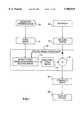
- a first image 10 which is to be hidden in a second image 12is modified 14 according to the contents of the second image to produce a modified first image 16 that will not be visible when combined with the second image.
- the modified first image 16is then added 18 to the second image to produce a combined image 20.
- the first and second images 10 and 12are preferably digital images.
- the first and second images 10 and 12are produced from an input device, for example by scanning a photographic image in a scanner 22 or by generating a computer graphic image on a graphics workstation 24.
- the first image 10may also be a pattern representing a digital data message, generated by the graphics workstation 24 or by another programmed computer. For example, the data image generated by the method disclosed in U.S. patent application Ser.
- No. 08/565,804, filed Nov. 30, 1995 by Daly et al.may comprise the first image 10.
- the first and second imagesmay also be supplied from a digital storage device such as a magnetic or optical memory.
- the image processing stepsare carried out in a digital image processor 26, such as a Sun Sparc5 workstation.
- the combined image 20will be displayed on a soft display device 28 such as a CRT or a hardcopy device such as a thermal, inkjet or digital silver halide printer.
- the first image 10is locally modified depending on the exact details of the second image 12 in the digital image processor 26.
- a model of the human visual systemis employed to perform this modification.
- the ability to model the human visual systemhas recently advanced to the state where it is possible to quantitatively predict the visibility of image distortions by treating the image as a 2-D waveform (See U.S. Pat. No. 5,394,483 issued Feburary 1995 to Daly).
- the method described in the '483 patentuses an advanced model of the human visual system to determine whether a distortion produced in an image will be visible in the image.
- the distortion and the imageare analyzed as collections of frequencies at each location in the image.
- the visibility of the distortionis determined with quantitative accuracy for each location in the image.
- This advanced model of the human visual systemis employed in the present invention to modify the first image according to the content of the second image so that when the modified first image is added to the second image to produce a combined image, no visible differences will exist between the second image and the combined image.
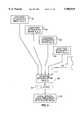
- the first and second images 10 and 12are processed through a parallel series of image processing steps in order to first simulate the effect the display device 28 will impose on the images, and then to simulate the perception of the images by the human visual system.
- the first step 30 in this processis to simulate the display system's tone scale response, which includes the quantization and clipping effects of the display.
- the next step 32is to simulate the display's spatial effects as represented by the modulation transfer function (MTF) which describes the 2-D frequency response of the display.
- MTFmodulation transfer function
- the displayhas been simulated and the resulting images are a representation of the physical 2-D waveform of light intensities produced by the display. From here the steps simulate the effects of the human visual system.
- the first step 34is to model the amplitude nonlinearity of the human retina, referred to as simply the cone nonlinearity. This is a simple pixel transformation may be accomplished, for example, with a look-up-table, since there are no spatial effects between different pixels. Alternatively, the transformation may be accomplished using an equation to compute the transformation.
- the exact shape of the nonlinearitydepends on the details of the viewing conditions such as overall light levels and is described in more detail in the '483 patent.
- the next step 36is to simulate the image independent spatial effects of the human visual system, which are obtained from a model of the contrast sensitivity function of the eye (CSF). The details of this effect depend on such viewing conditions such as light levels, viewing distance, and size of the image. The model which simulates these effects is described in more detail in the '483 patent.
- the next step 38is to simulate the frequency decomposition of the cortex of the visual system with a set of spatial frequency filters.
- This effectresults in the creation of one low-pass and a bank of band-pass filtered images (shown as multiple boxes for this step in the Figure). These are referred to as cortex filtered images and the filters used to create them are referred to as cortex filters.
- the exact number of filtered imagesis not critical, although the best performance occurs with about 31 filters as described in detail in the '483 patent.
- a masking image representing a degree of masking as a function of locationis created in step 40, this step is described in more detail in the '483 patent.
- Threshold elevationis the relative increase in visible threshold above that which would occur in a uniform field; this effect is commonly known as masking.
- the masking imagedescribes the threshold elevation as a function of position and spatial frequency within the image.
- the contrastis locally attenuated in step 42 as a function of the degree of masking for the corresponding cortex filtered image resulting from the second image 12. This step is described in more detail below with reference to FIG. 3.
- the resultis a new bank of cortex filtered images derived from the first image that will be below the visual threshold of the second image at each location within the second image.
- the new bank of cortex filtered imagesare accumulated in step 44 to substantially return the modified first image to the original spatial domain. This is essentially undoing step 38 after contrast attenuation.
- the modified first imageis further returned to the original domain in step 46, by applying a filter that is the inverse of the CSF.
- the modified first imageis combined 18 with a version of the second image which has been brought into the visual nonlinear domain (by steps 30, 32 and 34).
- a nonlinear domainsuch as the log domain or the cone nonlinear domain it will be an addition.
- the imagesare combined in a linear domain the combination will be effected by multiplication. This is because multiplication is simply an addition in the log domain (which is commonly used in images and referred to as density).
- the final stepis to return 48 the combined modified first and second images (which are now in a visual nonlinear domain) back into the physical image domain by using the inverse function of the cone nonlinearity to produce the final combined image 20.
- the modified first imagewill not cause a visible distortion of the second image for the viewing conditions specified by the components of the visual model used in steps 34 and 36.
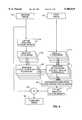
- FIG. 3is a diagram of the details of the Contrast Attenuation step 42 of FIG. 2. The details of this step are repeated for each cortex filtered image 50 created in step 38 from the first image 10.
- the other input to this stepis the corresponding masking image 52, which resulted from the second image 12 and shows the level of masking occurring in the second image as a function of location and frequency band.
- a low-pass filter 54may be applied to the masking image to simulate the phase uncertainty of the visual system. The use of this low-pass filter results in an accuracy versus computational complexity trade-off and is described in the '483 patent.
- the next step 56 applied to the masking image 52computes a maximum allowable local contrast C M (for the cortex filter band and the location in the image) calculated as: ##EQU1## where T E is the threshold elevation within the cortex filtered image generated from the second image, and P C is the psychometric function cutoff.
- the psychometric function cutoffrepresents the maximum allowed probability of detection of the first image in the second image, e.g. .5.
- the particular units of contrastare not important, as long as they are the same units of contrast as output in step 58 below.
- the contrast of the cortex filtered image 50may be normalized 58 and the contrast normalized image used in place of the cortex filtered image 50.
- the cortex filtered imageshave a mean pixel value of zero, the absolute value of each pixel in the image is taken 60 and the sign of each pixel is saved 62.
- step 62the sign of the local pixel contrast, S, was saved prior to the absolute value operation, and now that the amplitude of the local pixel contrast is determined in steps 66 and 68, the next step 70 is to provide the proper sign to the pixel's amplitude C A , by multiplying C A by S.
- the final step 72 in the contrast attenuation stepis optional, and that is to convert back from normalized contrast units to spatial units if the conversion to normalized contrast units was made in optional block 58.
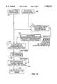
- FIG. 4shows a detailed diagram of an alternative contrast attenuation procedure 42.
- the procedurebegins with the masking image 52 and applies the low-pass filter 54 (phase uncertainty filter), which is not optional in this implementation.
- a similar low-pass filter 74is applied to the absolute value contrast image for the cortex frequency band of the first image. It generally has the same parameters as the filter 54, but it need not. The remaining steps in this method are similar to those described in FIG.
- step 76multiples the initial contrast in the first image which is output from step 60 by a scale factor C MU /C HU ; that is, it reduces the amplitude C H by the scale factor (C MU /C HU ) necessary to keep the amplitude less than the maximum allowable local contrast C MU over a locally broader range than as occurs in FIG. 3.
- the final steps 70 and 72are the same as FIG. 3.
- FIG. 5shows a detailed diagram of the contrast accumulation step 44 shown in FIG. 2. It takes input from the contrast attenuated images A n (i,j) 78, 80, 82, 84, 86, etc. resulting from the contrast attenuation steps 42 shown in FIG. 2 and detailed in FIGS. 3 and 4. There is a contrast attenuated image for each band n in the cortex filter bank 38. These are accumulated in step 88, which adds the pixels across all bands at a single location into a summation image ⁇ A n (i,j).
- step 88For the case where the local contrast of the entire first image lies below the maximum allowable threshold, then the first image is not changed and the result of the summation in step 88 is the same image resulting as the output of step 36 for the first image in FIG. 2. If the summed value exceeds the dynamic range of the desired output, an optional clipping step 90 may be employed to restrict the range of the pixel values in the modified first image. This will rarely be necessary since all the modifications made to the first image are in the form of a contrast attenuation, rather than a contrast increase.
- the output of this stepis the modified first image 92 which has been attenuated in the local spatial and frequency domains, based on the contents in the second image 12. The result is that this modified first image can now be added to the second image and no distortions will be visible to the human eye.
- FIG. 6shows an alternative method of hiding a first image within a second image, wherein the first image is already assumed to be in the visual domain.
- This versionis useful for applications where the first image is a pattern representing digital data, as opposed to another photographic image. It has the advantages of preserving high frequencies (they are not modified by a CSF filter 36 prior to the contrast accumulation step 44) and a slightly lower computational load for the hiding process (basically steps 30-36 for the first image shown in FIG. 2 are omitted).
- the step after the addition 18 of the modified first image to the second imageis to convert 48 the combined image from a domain corresponding to the visual nonlinearity to a domain common for imaging device representation (e.g., density or reflectance).
- the stepsinclude undoing the display MTF in step 100, and undoing the display tone scale in step 102 in order to return the combined image to its proper appearance.
- FIG. 7shows an alternative method over that of FIG. 6 where some computational burdens are removed at the expense of accuracy.
- the most cumbersomeis the inverse filtering of the display MTF (step 100 in FIG. 6).
- any steps after the addition 18must also be applied (in an inverse fashion) in the decoder. Consequently the alternate method of FIG. 7 dispenses with the compensation for the display MTF after step 18.
- This new pathwayincludes the separate simulation 104 of the display tone scale and the cone nonlinearity 34, respectively.
- the tone model used in step 104does not include the quantization and clipping steps used in the display tone model of step 30, thereby avoiding contouring artifacts due to multiple quantization of the image.
- the steps after the addition 18include applying the inverse of the amplitude nonlinearity 48 to the combined image and re-calibrating 102 the combined image back to the display space. These steps are simple operations which can be combined in a single look-up-table. Thus in a steganography application, the decoder only has to simulate steps 104 and 34 prior to its normal processing as described below with reference to FIG. 9.
- FIG. 8shows a further alternate method over FIG. 2, where several assumptions are made for the sake of computational efficiency.
- the first assumptionis that the image is in a gray-level domain that is already close to the gray-level domain of the cone nonlinearity.
- the common CRT gamma domainis a good example of such a domain.
- the displayhas no spatial effects on the image, thus we do not need to simulate such effects prior to entering the visual model, consequently step 32 of FIG. 2 is omitted.
- steps 48, 100, and 102 of FIG. 6also allow steps 48, 100, and 102 of FIG. 6 to be omitted, so that there is no processing after the addition of the second image to the modified first image.
- the decoderdoes not have to perform any of these steps either.
- the CSFis restricted to a low-pass version 110, and its viewing distance parameters can be specified in units of the image's picture heights.
- the CSFis restricted to a low-pass version 110, and its viewing distance parameters can be specified in units of the image's picture heights.
- the unmodified second image 12is added to the modified first image to create the embedded image in step 18.
- the advantages of this methodcome at the expense of a less accurate hiding process. This results in either visible artifacts in the embedded image or a situation in which the first image has lower overall contrast than if a more accurate method had been used. The lower overall contrast will make it more difficult for the decoder to extract data in steganography applications, and the visibility of the first image has the drawback of reducing the image quality of the combined image.
- a message 120 to be hidden in a second image 12is converted 122 to a multi-level 2-D data image.
- the multi-level data imageis an image having a constant background value and an array of spots on the background representing the digital data.
- a carrier imageis created 124.
- the encoding carrier imageis preferably a rotationally symmetric (isotropic), low amplitude, high frequency pattern (e.g. a chirp signal or pseudorandom noise) employed to spatially disperse the data image to mask its visibility when added to the source image.
- the data imageis convolved 126 with the encoding carrier image to form a frequency dispersed data image.
- the convolution 126is performed on a digital computer using a well known Fourier Transform method and digital versions of the data image and the encoding carrier image.
- the convolutionmay also be performed using a direct convolution algorithm on the digital computer.
- the frequency dispersed data imagemay be resized to a desired tile size 128 and the resized image may be repeated in a tiling fashion 130 to match the size of the second image 12.
- the resulting frequency dispersed data imagetakes the place of the first image 10 described previously.
- the first image 10is then modified 132 according to the second image 12 and added to the second image according to the present invention to produce a combined image 20.
- the combined imageis converted 134 to a digital image if necessary, for example by scanning, to create a digital version of the combined image 20.
- the digitized versionis then optionally processed 135 through the cone nonlinearity to return it to the domain where the modified first image and modified second image are added 18.
- This processwill consist of the inverses of any steps performed after the addition 18 and prior to the final combined image 20.
- an inverse cone nonlinearity 48is applied after the addition, so at this optional step 135, the inverse of the inverse of the cone nonlinearity is required. This is simply the cone nonlinearity 34.
- an inverse of the display MTF 100 and inverse display tone scale response 102are applied as well as the inverse of the cone nonlinearity 48 after the addition 18 to arrive at a final combined image 20.
- the decoder for digital steganographyshould remove these effects by processing the digitized image through the display tone scale response, the display MTF and the cone nonlinearity. Although this step is optional, it acts to increase the signal to noise ratio of detecting the data message and is the preferred embodiment.
- the combined imageis then desized 136 to undo the resizing that was performed on the first image in step 128.
- the desized combined imageis then cross correlated 138 with a carrier image created 140 in the same way as the carrier image that was created during the encoding step described above to generated an extracted data image.
- the two dimensional data imageis converted 140 to a one dimensional data sequence representing the original message 120.
- the digital datais converted from a digital version of the recovered data image using a pattern recognition process based on inverting the step 122 that was used to convert the message data to a 2-D data image.
- Visually lossless image compressionmay also be thought of as hiding one image within another, where the error between the original image and the image reconstructed from the compressed image may be thought of as an error image.
- the reconstructed imageis the combination of the error image and the original image.
- the goal of visually lossless compressionis to insure that the reconstructed image is visually identical to the original image. This is equivalent to hiding the error image within the original image.
- An image to be compressed in an adaptive manneris input to an adaptive lossy compression algorithm, such as the adaptive discrete cosine transform (DCT) process described in U.S. Pat. No. 4,774,574 issued Sep. 27, 1988 to Daly et al., or an adaptive wavelet compression technique.
- DCTadaptive discrete cosine transform
- a potential error image 150comprising for example a uniformly textured image consisting of high contrast 2-D white noise or a high amplitude basis set derived from the particular compression algorithm (e.g. for DCT the basis set consists of rectangularly windowed cosine functions; for wavelets, the basis set consists of the basis functions which increase in size as the decomposition proceeds to lower frequency pyramid levels).
- the potential error image 150is used as the first image in step 14, which is modified according to the image to be compressed, i.e. the second image, so that the modified first image would not be visible if added to the second image 12.
- This modified first imagerepresents the maximum allowable errors that may be introduced into the second image during compression without being visible.
- This maximum allowable error imageis employed in step 154 to determine the compression algorithm parameters specific to the second image as a function of location and frequency. For example, in the DCT compression technique, the maximum allowable quantization for each coefficient in each block is determined from the maximum error image.
- One way of implementing this for the DCT method of compressionis to first determine the DCT coefficients of the maximum error image for a corresponding block to be compressed.
- the nominal quantization value used for each coefficientis scaled by a function of the DCT coefficient of the maximum error image.
- the functionmay be a simple scale factor between 0.5 and 1.
- the second imageis then compressed 156 according to the adaptive compression algorithm whose parameters were selected in step 154.
- the compression algorithm parameters selected in step 154are appended to the compressed image and the compressed image along with the compression parameters is stored or transmitted 158.
- the compression parametersare retrieved from the compressed image file and are employed by the decompression algorithm to produce a reconstructed second image 162 that is visually equivalent to the second image 12.
- the present inventionmay be implemented as a method or apparatus on a general purpose digital computer configured to perform image processing applications. Additionally, the invention may be implemented as a computer program product by storing a program for implementing the steps of the method on a computer readable storage medium.
- the storage mediummay comprise for example; magnetic storage media such as magnetic disk (such as floppy disk) or magnetic tape; optical storage media such as optical disk, optical tape, or machine readable bar code; solid state electronic storage devices such as random access memory (RAM), or read only memory (ROM); or any other physical device or medium employed to store a digital computer program.
Landscapes
- Engineering & Computer Science (AREA)
- Multimedia (AREA)
- Signal Processing (AREA)
- Physics & Mathematics (AREA)
- General Physics & Mathematics (AREA)
- Theoretical Computer Science (AREA)
- Image Processing (AREA)
Abstract
Description
Claims (22)
Priority Applications (1)
| Application Number | Priority Date | Filing Date | Title |
|---|---|---|---|
| US08/596,818US5905819A (en) | 1996-02-05 | 1996-02-05 | Method and apparatus for hiding one image or pattern within another |
Applications Claiming Priority (1)
| Application Number | Priority Date | Filing Date | Title |
|---|---|---|---|
| US08/596,818US5905819A (en) | 1996-02-05 | 1996-02-05 | Method and apparatus for hiding one image or pattern within another |
Publications (1)
| Publication Number | Publication Date |
|---|---|
| US5905819Atrue US5905819A (en) | 1999-05-18 |
Family
ID=24388850
Family Applications (1)
| Application Number | Title | Priority Date | Filing Date |
|---|---|---|---|
| US08/596,818Expired - LifetimeUS5905819A (en) | 1996-02-05 | 1996-02-05 | Method and apparatus for hiding one image or pattern within another |
Country Status (1)
| Country | Link |
|---|---|
| US (1) | US5905819A (en) |
Cited By (137)
| Publication number | Priority date | Publication date | Assignee | Title |
|---|---|---|---|---|
| US6101278A (en)* | 1998-01-30 | 2000-08-08 | Philips Electronics North America Corp. | System for extracting coding parameters from video data |
| US6104812A (en)* | 1998-01-12 | 2000-08-15 | Juratrade, Limited | Anti-counterfeiting method and apparatus using digital screening |
| US6115485A (en)* | 1997-10-06 | 2000-09-05 | General Electric Company | Introducing reduced data set information into a primary image data set |
| US6173078B1 (en)* | 1996-10-30 | 2001-01-09 | Matsushita Electric Industrial Co., Ltd. | Image encoder, image encoding method, image decoder, image decoding method, and data recording medium |
| US6185312B1 (en)* | 1997-01-28 | 2001-02-06 | Nippon Telegraph And Telephone Corporation | Method for embedding and reading watermark-information in digital form, and apparatus thereof |
| US6192393B1 (en)* | 1998-04-07 | 2001-02-20 | Mgi Software Corporation | Method and system for panorama viewing |
| US6208735B1 (en) | 1997-09-10 | 2001-03-27 | Nec Research Institute, Inc. | Secure spread spectrum watermarking for multimedia data |
| US6226387B1 (en)* | 1996-08-30 | 2001-05-01 | Regents Of The University Of Minnesota | Method and apparatus for scene-based video watermarking |
| US6229924B1 (en) | 1996-05-16 | 2001-05-08 | Digimarc Corporation | Method and apparatus for watermarking video images |
| US6252971B1 (en)* | 1998-04-29 | 2001-06-26 | Xerox Corporation | Digital watermarking using phase-shifted stoclustic screens |
| US20010010730A1 (en)* | 1993-11-18 | 2001-08-02 | Rhoads Geoffrey B. | Steganographic messaging through imagery |
| US6282299B1 (en) | 1996-08-30 | 2001-08-28 | Regents Of The University Of Minnesota | Method and apparatus for video watermarking using perceptual masks |
| EP1139297A1 (en) | 2000-03-23 | 2001-10-04 | Eastman Kodak Company | A method for printing and verifying limited edition stamps |
| US6301360B1 (en)* | 1995-06-01 | 2001-10-09 | Siemens Aktiengesellschaft | Method of encoding information using a position-based encoding scheme |
| US6301368B1 (en)* | 1999-01-29 | 2001-10-09 | International Business Machines Corporation | System and method for data hiding in compressed fingerprint images |
| EP1152592A1 (en) | 2000-04-25 | 2001-11-07 | Eastman Kodak Company | A method for printing and verifying authentication documents |
| US20010041022A1 (en)* | 2000-02-11 | 2001-11-15 | Eric Edwards | System and method for editing digital images |
| US6331869B1 (en)* | 1998-08-07 | 2001-12-18 | Be Here Corporation | Method and apparatus for electronically distributing motion panoramic images |
| US6359998B1 (en)* | 1998-04-23 | 2002-03-19 | 3Com Corporation | Method and apparatus for wavelet-based digital watermarking |
| US6366685B1 (en)* | 1997-09-30 | 2002-04-02 | Canon Kabushiki Kaisha | Image processing apparatus and method and storing medium |
| US6370272B1 (en)* | 1997-04-07 | 2002-04-09 | International Business Machines Corporation | Multiple frame data hiding method and data detection method |
| US20020048282A1 (en)* | 1997-09-02 | 2002-04-25 | Osamu Kawamae | Data transmission method for embedded data, data transmitting and reproducing apparatuses and information recording medium therefor |
| US6381341B1 (en) | 1996-05-16 | 2002-04-30 | Digimarc Corporation | Watermark encoding method exploiting biases inherent in original signal |
| EP1107180A3 (en)* | 1999-12-03 | 2002-06-12 | Eastman Kodak Company | Storing sharpness data using embedded carriers |
| US6408082B1 (en) | 1996-04-25 | 2002-06-18 | Digimarc Corporation | Watermark detection using a fourier mellin transform |
| US6424725B1 (en) | 1996-05-16 | 2002-07-23 | Digimarc Corporation | Determining transformations of media signals with embedded code signals |
| US6433888B1 (en) | 1998-12-14 | 2002-08-13 | Eastman Kodak Company | Auto restoration of a print |
| US6434322B1 (en) | 1997-09-17 | 2002-08-13 | Hitachi, Ltd. | Reproducing method and apparatus, for a video signal having copy control information |
| US20020111987A1 (en)* | 1995-08-04 | 2002-08-15 | Belle Gate Investment B.V. | Data exchange system comprising portable data processing units |
| US20020121550A1 (en)* | 1999-12-06 | 2002-09-05 | Gorbet Matthew G. | Method and apparatus for display of spatially registered information using embedded data |
| US6456726B1 (en)* | 1999-10-26 | 2002-09-24 | Matsushita Electric Industrial Co., Ltd. | Methods and apparatus for multi-layer data hiding |
| US20020146123A1 (en)* | 2000-11-08 | 2002-10-10 | Jun Tian | Content authentication and recovery using digital watermarks |
| US20020164052A1 (en)* | 2000-04-19 | 2002-11-07 | Reed Alastair M. | Enhancing embedding of out-of-phase signals |
| US20020168085A1 (en)* | 2000-04-19 | 2002-11-14 | Reed Alastair M. | Hiding information out-of-phase in color channels |
| US20020169721A1 (en)* | 2001-05-10 | 2002-11-14 | Cooley William Ray | Digital watermarking apparatus, systems and methods |
| EP1259078A1 (en)* | 2001-05-14 | 2002-11-20 | Institut Eurecom G.I.E. | Method of marking a multimedia document having improved robustness |
| US20020191812A1 (en)* | 2001-04-24 | 2002-12-19 | Nam-Deuk Kim | Object edge watermarking |
| US6501860B1 (en)* | 1998-01-19 | 2002-12-31 | Canon Kabushiki Kaisha | Digital signal coding and decoding based on subbands |
| US20030016842A1 (en)* | 2001-07-23 | 2003-01-23 | Patton Charles M. | Digital content with information of latent value to purchaser and method for making the same |
| US20030021439A1 (en)* | 2001-07-30 | 2003-01-30 | Jeffrey Lubin | Secure robust high-fidelity watermarking |
| US20030035564A1 (en)* | 2001-08-15 | 2003-02-20 | Eastman Kodak Company | Authenticatable image with an embedded image having a discernible physical characteristic with improved security feature |
| US6553129B1 (en) | 1995-07-27 | 2003-04-22 | Digimarc Corporation | Computer system linked by using information in data objects |
| US6567533B1 (en) | 1993-11-18 | 2003-05-20 | Digimarc Corporation | Method and apparatus for discerning image distortion by reference to encoded marker signals |
| US20030103246A1 (en)* | 2001-11-30 | 2003-06-05 | Eastman Kodak Company | System and method for providing unobtrusive human visible information on a print |
| US6584210B1 (en) | 1998-03-27 | 2003-06-24 | Hitachi, Ltd. | Digital watermark image processing method |
| WO2003051643A1 (en)* | 2001-12-18 | 2003-06-26 | Nanosolutions Gmbh | Printing method with coded individual control of nozzles |
| US6611607B1 (en) | 1993-11-18 | 2003-08-26 | Digimarc Corporation | Integrating digital watermarks in multimedia content |
| US6614914B1 (en) | 1995-05-08 | 2003-09-02 | Digimarc Corporation | Watermark embedder and reader |
| US6631198B1 (en)* | 2000-06-19 | 2003-10-07 | Digimarc Corporation | Perceptual modeling of media signals based on local contrast and directional edges |
| US6633654B2 (en) | 2000-06-19 | 2003-10-14 | Digimarc Corporation | Perceptual modeling of media signals based on local contrast and directional edges |
| US20030206662A1 (en)* | 2002-05-03 | 2003-11-06 | Avinash Gopal B. | Method and apparatus for improving perceived digital image quality |
| US6647125B2 (en)* | 1997-07-17 | 2003-11-11 | Canon Kabushiki Kaisha | Image processing apparatus, method and recording medium therefor |
| US6654479B1 (en)* | 1999-08-19 | 2003-11-25 | Academia Sinica | Cocktail watermarking on images |
| US6674923B1 (en) | 2000-03-28 | 2004-01-06 | Eastman Kodak Company | Method and system for locating and accessing digitally stored images |
| US6678425B1 (en) | 1999-12-06 | 2004-01-13 | Xerox Corporation | Method and apparatus for decoding angular orientation of lattice codes |
| US20040046774A1 (en)* | 2001-03-05 | 2004-03-11 | Rhoads Geoffrey B. | Image management system and methods using digital watermarks |
| US6707926B1 (en)* | 2000-03-31 | 2004-03-16 | Intel Corporation | Template for watermark decoder synchronization |
| US6718046B2 (en) | 1995-05-08 | 2004-04-06 | Digimarc Corporation | Low visibility watermark using time decay fluorescence |
| US6721438B1 (en)* | 1999-03-30 | 2004-04-13 | Canon Kabushiki Kaisha | Image processing apparatus, image processing method, and storage medium |
| US6721440B2 (en) | 1995-05-08 | 2004-04-13 | Digimarc Corporation | Low visibility watermarks using an out-of-phase color |
| US20040074973A1 (en)* | 2002-04-09 | 2004-04-22 | Nelson Schneck | Image processing techniques for printing identification cards and documents |
| US6728408B1 (en) | 1997-09-03 | 2004-04-27 | Hitachi, Ltd. | Water-mark embedding method and system |
| EP1173001A3 (en)* | 2000-07-11 | 2004-05-06 | Eastman Kodak Company | Authenticatable image with an embedded image having a discernible physical characteristic |
| US20040091131A1 (en)* | 2002-11-12 | 2004-05-13 | Eastman Kodak Company | Method of authenication for steganographic signals undergoing degradations |
| US6744905B1 (en)* | 1998-03-25 | 2004-06-01 | Canon Kabushiki Kaisha | Image processing apparatus and method, and storage medium storing program codes realizing such method |
| US20040125952A1 (en)* | 2002-01-22 | 2004-07-01 | Alattar Adnan M. | Digital watermarking of low bit rate video |
| US6763123B2 (en) | 1995-05-08 | 2004-07-13 | Digimarc Corporation | Detection of out-of-phase low visibility watermarks |
| US6768809B2 (en) | 2000-02-14 | 2004-07-27 | Digimarc Corporation | Digital watermark screening and detection strategies |
| US20040146161A1 (en)* | 1998-09-29 | 2004-07-29 | Sun Microsystems, Inc. | Superposition of data over voice |
| US6775394B2 (en) | 2002-03-12 | 2004-08-10 | Matsushita Electric Industrial Co., Ltd. | Digital watermarking of binary document using halftoning |
| US6783069B1 (en) | 1999-12-06 | 2004-08-31 | Xerox Corporation | Method and apparatus for implementing a camera mouse |
| US6788800B1 (en)* | 2000-07-25 | 2004-09-07 | Digimarc Corporation | Authenticating objects using embedded data |
| US20040187004A1 (en)* | 2003-03-14 | 2004-09-23 | Eastman Kodak Company | Method of embedding and extracting information using induced affine transformations |
| US6801999B1 (en)* | 1999-05-20 | 2004-10-05 | Microsoft Corporation | Passive and active software objects containing bore resistant watermarking |
| US6804377B2 (en) | 2000-04-19 | 2004-10-12 | Digimarc Corporation | Detecting information hidden out-of-phase in color channels |
| US20040223626A1 (en)* | 2003-05-09 | 2004-11-11 | Eastman Kodak Company | Method for embedding spatially variant metadata in imagery |
| US6826291B2 (en) | 1997-09-03 | 2004-11-30 | Hitachi, Ltd. | Method and system for embedding information into contents |
| US20040240704A1 (en)* | 2000-04-19 | 2004-12-02 | Reed Alastair M. | Applying digital watermarks using printing process correction |
| US20040240705A1 (en)* | 2003-05-29 | 2004-12-02 | Jeffrey Lubin | Method and apparatus for analog insertion of low frequency watermarks |
| US6879701B1 (en) | 1994-10-21 | 2005-04-12 | Digimarc Corporation | Tile-based digital watermarking techniques |
| US20050077351A1 (en)* | 1999-12-07 | 2005-04-14 | Sun Microsystems, Inc. | Secure photo carrying identification device, as well as means and method for authenticating such an identification device |
| US20050114211A1 (en)* | 2003-10-07 | 2005-05-26 | Kamran Amjadi | System and method for preventing coupon fraud |
| US20050156048A1 (en)* | 2001-08-31 | 2005-07-21 | Reed Alastair M. | Machine-readable security features for printed objects |
| US20050160294A1 (en)* | 2001-12-18 | 2005-07-21 | Labrec Brian C. | Multiple image security features for identification documents and methods of making same |
| US6978371B1 (en)* | 2000-11-07 | 2005-12-20 | Matsushita Electric Industrial Co., Ltd. | Data hiding in digital multimedia |
| US20050283579A1 (en)* | 1999-06-10 | 2005-12-22 | Belle Gate Investment B.V. | Arrangements storing different versions of a set of data in separate memory areas and method for updating a set of data in a memory |
| US20060008112A1 (en)* | 2000-04-19 | 2006-01-12 | Reed Alastair M | Low visible digital watermarks |
| US6993719B1 (en) | 2000-02-11 | 2006-01-31 | Sony Corporation | System and method for animated character photo-editing interface and cross-platform education icon |
| US20060023260A1 (en)* | 2004-07-28 | 2006-02-02 | Kabushiki Kaisha Toshiba | Image processing method, image printing method, image printing mechanism and printed matter |
| US7027614B2 (en) | 2000-04-19 | 2006-04-11 | Digimarc Corporation | Hiding information to reduce or offset perceptible artifacts |
| US7050195B1 (en)* | 2000-04-20 | 2006-05-23 | Hewlett-Packard Development Company, L.P. | Printed medium data storage |
| US7080261B1 (en) | 1999-12-07 | 2006-07-18 | Sun Microsystems, Inc. | Computer-readable medium with microprocessor to control reading and computer arranged to communicate with such a medium |
| US20060193004A1 (en)* | 2001-02-08 | 2006-08-31 | Eastman Kodak Company | Method of integrating imaging products/services with non-imaging products/services in a single kiosk |
| US7136070B1 (en)* | 1999-12-06 | 2006-11-14 | Nvidia Corporation | System, method and computer program product for using an arbitrary quantity as texture address |
| US20070104350A1 (en)* | 2005-11-10 | 2007-05-10 | Oki Electric Industry Co., Ltd. | Watermarked information embedding apparatus |
| US20070183455A1 (en)* | 2004-03-12 | 2007-08-09 | Koninklijke Philips Electronics, N.V. | Method of inserting digital watermarks in one-bit audio files |
| US7262778B1 (en) | 2000-02-11 | 2007-08-28 | Sony Corporation | Automatic color adjustment of a template design |
| US20070246543A1 (en)* | 2001-08-31 | 2007-10-25 | Jones Robert L | Security Features for Objects and Method Regarding Same |
| US20080149713A1 (en)* | 2003-08-13 | 2008-06-26 | Brundage Trent J | Detecting Media Areas Likely of Hosting Watermarks |
| US20080226120A1 (en)* | 1997-07-24 | 2008-09-18 | Ahmed Tewfik | Video Watermarking Using Temporal Analysis |
| US7486799B2 (en) | 1995-05-08 | 2009-02-03 | Digimarc Corporation | Methods for monitoring audio and images on the internet |
| US7577841B2 (en) | 2002-08-15 | 2009-08-18 | Digimarc Corporation | Watermark placement in watermarking of time varying media signals |
| US7694887B2 (en) | 2001-12-24 | 2010-04-13 | L-1 Secure Credentialing, Inc. | Optically variable personalized indicia for identification documents |
| US20100150434A1 (en)* | 2008-12-17 | 2010-06-17 | Reed Alastair M | Out of Phase Digital Watermarking in Two Chrominance Directions |
| US20100163629A1 (en)* | 1995-05-08 | 2010-07-01 | Rhoads Geoffrey B | Security Document Carrying Machine Readable Pattern |
| US20100226525A1 (en)* | 1996-04-25 | 2010-09-09 | Levy Kenneth L | Processing Audio or Video Content with Multiple Watermark Layers |
| US7798413B2 (en) | 2001-12-24 | 2010-09-21 | L-1 Secure Credentialing, Inc. | Covert variable information on ID documents and methods of making same |
| US7824029B2 (en) | 2002-05-10 | 2010-11-02 | L-1 Secure Credentialing, Inc. | Identification card printer-assembler for over the counter card issuing |
| US7828218B1 (en) | 2000-07-20 | 2010-11-09 | Oracle America, Inc. | Method and system of communicating devices, and devices therefor, with protected data transfer |
| US8000495B2 (en) | 1995-07-27 | 2011-08-16 | Digimarc Corporation | Digital watermarking systems and methods |
| US8027509B2 (en) | 2000-04-19 | 2011-09-27 | Digimarc Corporation | Digital watermarking in data representing color channels |
| US20110292439A1 (en)* | 2010-05-25 | 2011-12-01 | Ricoh Company, Ltd. | Image processing apparatus and Image Processing method |
| US8090141B2 (en) | 2006-01-31 | 2012-01-03 | Xerox Corporation | System and method to automatically establish preferred area for image-wise watermark |
| US8094869B2 (en)* | 2001-07-02 | 2012-01-10 | Digimarc Corporation | Fragile and emerging digital watermarks |
| US8199969B2 (en) | 2008-12-17 | 2012-06-12 | Digimarc Corporation | Out of phase digital watermarking in two chrominance directions |
| WO2012166843A2 (en) | 2011-06-03 | 2012-12-06 | Eastman Kodak Company | Method for making a z-fold signature |
| US8505897B2 (en) | 2011-06-03 | 2013-08-13 | Eastman Kodak Company | Z-fold signature finishing system and printer |
| US8505898B2 (en) | 2011-06-03 | 2013-08-13 | Eastman Kodak Company | Method for making a Z-fold signature |
| US20130294706A1 (en)* | 2012-05-04 | 2013-11-07 | Environmental Systems Research Institute (ESRI) | Limited error raster compression |
| WO2015061009A1 (en) | 2013-10-21 | 2015-04-30 | Carestream Health, Inc. | Invisible patterns for transparent electrically conductive films |
| US9241128B2 (en) | 2013-02-14 | 2016-01-19 | Warner Bros. Entertainment Inc. | Video conversion technology |
| US9275456B2 (en)* | 2010-10-29 | 2016-03-01 | The Johns Hopkins University | Image search engine |
| US20160127746A1 (en)* | 2012-05-04 | 2016-05-05 | Environmental Systems Research Institute, Inc. | Limited error raster compression |
| US9380186B2 (en) | 2012-08-24 | 2016-06-28 | Digimarc Corporation | Data hiding for spot colors in product packaging |
| US9396509B1 (en) | 2011-10-30 | 2016-07-19 | Digimarc Corporation | Closed form non-iterative watermark embedding |
| US9401001B2 (en) | 2014-01-02 | 2016-07-26 | Digimarc Corporation | Full-color visibility model using CSF which varies spatially with local luminance |
| US9449357B1 (en) | 2012-08-24 | 2016-09-20 | Digimarc Corporation | Geometric enumerated watermark embedding for spot colors |
| US9565335B2 (en) | 2014-01-02 | 2017-02-07 | Digimarc Corporation | Full color visibility model using CSF which varies spatially with local luminance |
| US9805195B1 (en)* | 2013-09-17 | 2017-10-31 | The Boeing Company | System and method for transferring files between computer systems using information invariant data transformation |
| WO2018165667A1 (en) | 2017-03-10 | 2018-09-13 | Digimarc Corporation | Predicting detectability and grading prior to printing |
| US10270936B2 (en) | 2014-08-12 | 2019-04-23 | Digimarc Corporation | Encoding signals in color designs for physical objects |
| US10506128B1 (en) | 2017-06-16 | 2019-12-10 | Digimarc Corporation | Encoded signal systems and methods to ensure minimal robustness |
| US10880451B2 (en) | 2018-06-08 | 2020-12-29 | Digimarc Corporation | Aggregating detectability metrics to determine signal robustness |
| US10986245B2 (en) | 2017-06-16 | 2021-04-20 | Digimarc Corporation | Encoded signal systems and methods to ensure minimal robustness |
| US11263829B2 (en) | 2012-01-02 | 2022-03-01 | Digimarc Corporation | Using a predicted color for both visibility evaluation and signal robustness evaluation |
| US11548310B2 (en) | 2004-11-09 | 2023-01-10 | Digimarc Corporation | Authenticating identification and security documents and other objects |
| US11810378B2 (en) | 2012-08-24 | 2023-11-07 | Digimarc Corporation | Data hiding through optimization of color error and modulation error |
Citations (15)
| Publication number | Priority date | Publication date | Assignee | Title |
|---|---|---|---|---|
| US4774574A (en)* | 1987-06-02 | 1988-09-27 | Eastman Kodak Company | Adaptive block transform image coding method and apparatus |
| US5091966A (en)* | 1990-07-31 | 1992-02-25 | Xerox Corporation | Adaptive scaling for decoding spatially periodic self-clocking glyph shape codes |
| EP0493091A1 (en)* | 1990-12-27 | 1992-07-01 | Xerox Corporation | Method and system for embedding machine readable digital data in grayscale images |
| US5128525A (en)* | 1990-07-31 | 1992-07-07 | Xerox Corporation | Convolution filtering for decoding self-clocking glyph shape codes |
| US5168147A (en)* | 1990-07-31 | 1992-12-01 | Xerox Corporation | Binary image processing for decoding self-clocking glyph shape codes |
| US5221833A (en)* | 1991-12-27 | 1993-06-22 | Xerox Corporation | Methods and means for reducing bit error rates in reading self-clocking glyph codes |
| US5245165A (en)* | 1991-12-27 | 1993-09-14 | Xerox Corporation | Self-clocking glyph code for encoding dual bit digital values robustly |
| EP0581317A2 (en)* | 1992-07-31 | 1994-02-02 | Corbis Corporation | Method and system for digital image signatures |
| US5323247A (en)* | 1990-12-04 | 1994-06-21 | Research Corporation Technologies | Method and apparatus for halftoning and inverse halftoning and the transmission of such images |
| US5327254A (en)* | 1992-02-19 | 1994-07-05 | Daher Mohammad A | Method and apparatus for compressing and decompressing image data |
| US5347590A (en)* | 1991-06-10 | 1994-09-13 | General Electric Company | Spatial filter for an image processing system |
| US5394483A (en)* | 1992-06-30 | 1995-02-28 | Eastman Kodak Co | Method and apparatus for determining visually perceptible differences between images |
| US5521723A (en)* | 1994-06-16 | 1996-05-28 | Eastman Kodak Company | System for producing a color hardcopy having the color and the tone reproduction characteristics of a photograph |
| US5557429A (en)* | 1992-10-20 | 1996-09-17 | Fuji Xerox Co., Ltd. | Image signal processing apparatus |
| US5636292A (en)* | 1995-05-08 | 1997-06-03 | Digimarc Corporation | Steganography methods employing embedded calibration data |
- 1996
- 1996-02-05USUS08/596,818patent/US5905819A/ennot_activeExpired - Lifetime
Patent Citations (16)
| Publication number | Priority date | Publication date | Assignee | Title |
|---|---|---|---|---|
| US4774574A (en)* | 1987-06-02 | 1988-09-27 | Eastman Kodak Company | Adaptive block transform image coding method and apparatus |
| US5168147A (en)* | 1990-07-31 | 1992-12-01 | Xerox Corporation | Binary image processing for decoding self-clocking glyph shape codes |
| US5091966A (en)* | 1990-07-31 | 1992-02-25 | Xerox Corporation | Adaptive scaling for decoding spatially periodic self-clocking glyph shape codes |
| US5128525A (en)* | 1990-07-31 | 1992-07-07 | Xerox Corporation | Convolution filtering for decoding self-clocking glyph shape codes |
| US5323247A (en)* | 1990-12-04 | 1994-06-21 | Research Corporation Technologies | Method and apparatus for halftoning and inverse halftoning and the transmission of such images |
| EP0493091A1 (en)* | 1990-12-27 | 1992-07-01 | Xerox Corporation | Method and system for embedding machine readable digital data in grayscale images |
| US5347590A (en)* | 1991-06-10 | 1994-09-13 | General Electric Company | Spatial filter for an image processing system |
| US5221833A (en)* | 1991-12-27 | 1993-06-22 | Xerox Corporation | Methods and means for reducing bit error rates in reading self-clocking glyph codes |
| US5245165A (en)* | 1991-12-27 | 1993-09-14 | Xerox Corporation | Self-clocking glyph code for encoding dual bit digital values robustly |
| US5327254A (en)* | 1992-02-19 | 1994-07-05 | Daher Mohammad A | Method and apparatus for compressing and decompressing image data |
| US5394483A (en)* | 1992-06-30 | 1995-02-28 | Eastman Kodak Co | Method and apparatus for determining visually perceptible differences between images |
| EP0581317A2 (en)* | 1992-07-31 | 1994-02-02 | Corbis Corporation | Method and system for digital image signatures |
| US5557429A (en)* | 1992-10-20 | 1996-09-17 | Fuji Xerox Co., Ltd. | Image signal processing apparatus |
| US5521723A (en)* | 1994-06-16 | 1996-05-28 | Eastman Kodak Company | System for producing a color hardcopy having the color and the tone reproduction characteristics of a photograph |
| US5636292A (en)* | 1995-05-08 | 1997-06-03 | Digimarc Corporation | Steganography methods employing embedded calibration data |
| US5636292C1 (en)* | 1995-05-08 | 2002-06-18 | Digimarc Corp | Steganography methods employing embedded calibration data |
Non-Patent Citations (4)
| Title |
|---|
| Matsui, et al "Video-Steganography: How to Secretly Embed a Signature in a Picture", the Journal of the Interactive Multimedia Association Intellectual Property Project, vol. 1, issue 1, Jan. 1994. |
| Matsui, et al Video Steganography: How to Secretly Embed a Signature in a Picture , the Journal of the Interactive Multimedia Association Intellectual Property Project, vol. 1, issue 1, Jan. 1994.* |
| Walter Bender et al., "Techniques for Data Hiding", Feb. 1995, From the Proceedings of the SPIE, 2420:40, pp. 1-10. |
| Walter Bender et al., Techniques for Data Hiding , Feb. 1995, From the Proceedings of the SPIE, 2420:40, pp. 1 10.* |
Cited By (246)
| Publication number | Priority date | Publication date | Assignee | Title |
|---|---|---|---|---|
| US6567533B1 (en) | 1993-11-18 | 2003-05-20 | Digimarc Corporation | Method and apparatus for discerning image distortion by reference to encoded marker signals |
| US6975746B2 (en) | 1993-11-18 | 2005-12-13 | Digimarc Corporation | Integrating digital watermarks in multimedia content |
| US6700990B1 (en) | 1993-11-18 | 2004-03-02 | Digimarc Corporation | Digital watermark decoding method |
| US7992003B2 (en) | 1993-11-18 | 2011-08-02 | Digimarc Corporation | Methods and systems for inserting watermarks in digital signals |
| US7171016B1 (en) | 1993-11-18 | 2007-01-30 | Digimarc Corporation | Method for monitoring internet dissemination of image, video and/or audio files |
| US20060251291A1 (en)* | 1993-11-18 | 2006-11-09 | Rhoads Geoffrey B | Methods for inserting and detecting watermarks in digital data |
| US7945781B1 (en) | 1993-11-18 | 2011-05-17 | Digimarc Corporation | Method and systems for inserting watermarks in digital signals |
| US8184851B2 (en) | 1993-11-18 | 2012-05-22 | Digimarc Corporation | Inserting watermarks into portions of digital signals |
| US6611607B1 (en) | 1993-11-18 | 2003-08-26 | Digimarc Corporation | Integrating digital watermarks in multimedia content |
| US20010010730A1 (en)* | 1993-11-18 | 2001-08-02 | Rhoads Geoffrey B. | Steganographic messaging through imagery |
| US6879701B1 (en) | 1994-10-21 | 2005-04-12 | Digimarc Corporation | Tile-based digital watermarking techniques |
| US6721440B2 (en) | 1995-05-08 | 2004-04-13 | Digimarc Corporation | Low visibility watermarks using an out-of-phase color |
| US6763123B2 (en) | 1995-05-08 | 2004-07-13 | Digimarc Corporation | Detection of out-of-phase low visibility watermarks |
| US6718047B2 (en) | 1995-05-08 | 2004-04-06 | Digimarc Corporation | Watermark embedder and reader |
| US7486799B2 (en) | 1995-05-08 | 2009-02-03 | Digimarc Corporation | Methods for monitoring audio and images on the internet |
| US8009893B2 (en) | 1995-05-08 | 2011-08-30 | Digimarc Corporation | Security document carrying machine readable pattern |
| US6718046B2 (en) | 1995-05-08 | 2004-04-06 | Digimarc Corporation | Low visibility watermark using time decay fluorescence |
| US20100163629A1 (en)* | 1995-05-08 | 2010-07-01 | Rhoads Geoffrey B | Security Document Carrying Machine Readable Pattern |
| US6614914B1 (en) | 1995-05-08 | 2003-09-02 | Digimarc Corporation | Watermark embedder and reader |
| US6301360B1 (en)* | 1995-06-01 | 2001-10-09 | Siemens Aktiengesellschaft | Method of encoding information using a position-based encoding scheme |
| US8000495B2 (en) | 1995-07-27 | 2011-08-16 | Digimarc Corporation | Digital watermarking systems and methods |
| US6553129B1 (en) | 1995-07-27 | 2003-04-22 | Digimarc Corporation | Computer system linked by using information in data objects |
| US6775392B1 (en) | 1995-07-27 | 2004-08-10 | Digimarc Corporation | Computer system linked by using information in data objects |
| US7185110B2 (en) | 1995-08-04 | 2007-02-27 | Sun Microsystems, Inc. | Data exchange system comprising portable data processing units |
| US20020111987A1 (en)* | 1995-08-04 | 2002-08-15 | Belle Gate Investment B.V. | Data exchange system comprising portable data processing units |
| US20100226525A1 (en)* | 1996-04-25 | 2010-09-09 | Levy Kenneth L | Processing Audio or Video Content with Multiple Watermark Layers |
| US8103879B2 (en) | 1996-04-25 | 2012-01-24 | Digimarc Corporation | Processing audio or video content with multiple watermark layers |
| US6408082B1 (en) | 1996-04-25 | 2002-06-18 | Digimarc Corporation | Watermark detection using a fourier mellin transform |
| US6424725B1 (en) | 1996-05-16 | 2002-07-23 | Digimarc Corporation | Determining transformations of media signals with embedded code signals |
| US6381341B1 (en) | 1996-05-16 | 2002-04-30 | Digimarc Corporation | Watermark encoding method exploiting biases inherent in original signal |
| US6229924B1 (en) | 1996-05-16 | 2001-05-08 | Digimarc Corporation | Method and apparatus for watermarking video images |
| US6798894B2 (en) | 1996-05-16 | 2004-09-28 | Digimarc Corporation | Method and apparatus for watermarking video images |
| US6226387B1 (en)* | 1996-08-30 | 2001-05-01 | Regents Of The University Of Minnesota | Method and apparatus for scene-based video watermarking |
| US6282299B1 (en) | 1996-08-30 | 2001-08-28 | Regents Of The University Of Minnesota | Method and apparatus for video watermarking using perceptual masks |
| US6487315B2 (en) | 1996-10-30 | 2002-11-26 | Matsushita Electric Industrial Co., Ltd. | Image decoding apparatus using pixel values from at least three reference pixels |
| US6748117B2 (en) | 1996-10-30 | 2004-06-08 | Matsushita Electric Industrial Co., Ltd. | Image decoding apparatus using pixel values from at least three reference pixels |
| US6487314B1 (en) | 1996-10-30 | 2002-11-26 | Matsushita Electric Industrial Co., Ltd. | Image decoding apparatus using pixel values from at least three references pixels |
| US6173078B1 (en)* | 1996-10-30 | 2001-01-09 | Matsushita Electric Industrial Co., Ltd. | Image encoder, image encoding method, image decoder, image decoding method, and data recording medium |
| US6185312B1 (en)* | 1997-01-28 | 2001-02-06 | Nippon Telegraph And Telephone Corporation | Method for embedding and reading watermark-information in digital form, and apparatus thereof |
| US6370272B1 (en)* | 1997-04-07 | 2002-04-09 | International Business Machines Corporation | Multiple frame data hiding method and data detection method |
| US6647125B2 (en)* | 1997-07-17 | 2003-11-11 | Canon Kabushiki Kaisha | Image processing apparatus, method and recording medium therefor |
| US8155375B2 (en)* | 1997-07-24 | 2012-04-10 | Regents Of The University Of Minnesota | Video watermarking using temporal analysis |
| US20080226120A1 (en)* | 1997-07-24 | 2008-09-18 | Ahmed Tewfik | Video Watermarking Using Temporal Analysis |
| US7139408B2 (en) | 1997-08-26 | 2006-11-21 | Digimarc Corporation | Transform domain watermarking of image signals |
| US20050036657A1 (en)* | 1997-08-26 | 2005-02-17 | Rhoads Geoffrey B. | Transform domain watermarking of image signals |
| US7949147B2 (en) | 1997-08-26 | 2011-05-24 | Digimarc Corporation | Watermarking compressed data |
| US6404781B1 (en) | 1997-09-02 | 2002-06-11 | Hitachi, Ltd. | Data transmission method for embedded data, data transmitting and reproducing apparatuses and information recording medium therefor |
| US7248607B2 (en) | 1997-09-02 | 2007-07-24 | Hitachi, Ltd. | Data transmission method for embedded data, data transmitting and reproducing apparatuses and information recording medium therefor |
| US7317738B2 (en) | 1997-09-02 | 2008-01-08 | Hitachi, Ltd. | Data transmission method for embedded data, data transmitting and reproducing apparatuses and information recording medium therefor |
| US20020049953A1 (en)* | 1997-09-02 | 2002-04-25 | Osamu Kawamae | Data transmission method for embedded data, data transmitting and reproducing apparatuses and information recording medium therefor |
| US20020048282A1 (en)* | 1997-09-02 | 2002-04-25 | Osamu Kawamae | Data transmission method for embedded data, data transmitting and reproducing apparatuses and information recording medium therefor |
| US6728408B1 (en) | 1997-09-03 | 2004-04-27 | Hitachi, Ltd. | Water-mark embedding method and system |
| US6826291B2 (en) | 1997-09-03 | 2004-11-30 | Hitachi, Ltd. | Method and system for embedding information into contents |
| US6208735B1 (en) | 1997-09-10 | 2001-03-27 | Nec Research Institute, Inc. | Secure spread spectrum watermarking for multimedia data |
| US6434322B1 (en) | 1997-09-17 | 2002-08-13 | Hitachi, Ltd. | Reproducing method and apparatus, for a video signal having copy control information |
| US6366685B1 (en)* | 1997-09-30 | 2002-04-02 | Canon Kabushiki Kaisha | Image processing apparatus and method and storing medium |
| US6115485A (en)* | 1997-10-06 | 2000-09-05 | General Electric Company | Introducing reduced data set information into a primary image data set |
| US6571020B1 (en) | 1997-10-06 | 2003-05-27 | General Electric Company | Introducing reduced dataset information into a primary image dataset |
| US6104812A (en)* | 1998-01-12 | 2000-08-15 | Juratrade, Limited | Anti-counterfeiting method and apparatus using digital screening |
| US6501860B1 (en)* | 1998-01-19 | 2002-12-31 | Canon Kabushiki Kaisha | Digital signal coding and decoding based on subbands |
| US6101278A (en)* | 1998-01-30 | 2000-08-08 | Philips Electronics North America Corp. | System for extracting coding parameters from video data |
| US6744905B1 (en)* | 1998-03-25 | 2004-06-01 | Canon Kabushiki Kaisha | Image processing apparatus and method, and storage medium storing program codes realizing such method |
| US6584210B1 (en) | 1998-03-27 | 2003-06-24 | Hitachi, Ltd. | Digital watermark image processing method |
| US6192393B1 (en)* | 1998-04-07 | 2001-02-20 | Mgi Software Corporation | Method and system for panorama viewing |
| US6359998B1 (en)* | 1998-04-23 | 2002-03-19 | 3Com Corporation | Method and apparatus for wavelet-based digital watermarking |
| US6252971B1 (en)* | 1998-04-29 | 2001-06-26 | Xerox Corporation | Digital watermarking using phase-shifted stoclustic screens |
| US6331869B1 (en)* | 1998-08-07 | 2001-12-18 | Be Here Corporation | Method and apparatus for electronically distributing motion panoramic images |
| US20040146161A1 (en)* | 1998-09-29 | 2004-07-29 | Sun Microsystems, Inc. | Superposition of data over voice |
| US7145991B2 (en) | 1998-09-29 | 2006-12-05 | Sun Microsystem, Inc. | Superposition of data over voice |
| US6433888B1 (en) | 1998-12-14 | 2002-08-13 | Eastman Kodak Company | Auto restoration of a print |
| US6301368B1 (en)* | 1999-01-29 | 2001-10-09 | International Business Machines Corporation | System and method for data hiding in compressed fingerprint images |
| US6721438B1 (en)* | 1999-03-30 | 2004-04-13 | Canon Kabushiki Kaisha | Image processing apparatus, image processing method, and storage medium |
| US6801999B1 (en)* | 1999-05-20 | 2004-10-05 | Microsoft Corporation | Passive and active software objects containing bore resistant watermarking |
| US7360039B2 (en) | 1999-06-10 | 2008-04-15 | Belle Gate Investment B.V. | Arrangements storing different versions of a set of data in separate memory areas and method for updating a set of data in a memory |
| US20050283579A1 (en)* | 1999-06-10 | 2005-12-22 | Belle Gate Investment B.V. | Arrangements storing different versions of a set of data in separate memory areas and method for updating a set of data in a memory |
| US6788801B2 (en)* | 1999-08-19 | 2004-09-07 | Academia Sinica | Cocktail watermarking on images |
| US6654479B1 (en)* | 1999-08-19 | 2003-11-25 | Academia Sinica | Cocktail watermarking on images |
| US6456726B1 (en)* | 1999-10-26 | 2002-09-24 | Matsushita Electric Industrial Co., Ltd. | Methods and apparatus for multi-layer data hiding |
| EP1107180A3 (en)* | 1999-12-03 | 2002-06-12 | Eastman Kodak Company | Storing sharpness data using embedded carriers |
| US6721459B1 (en) | 1999-12-03 | 2004-04-13 | Eastman Kodak Company | Storing sharpness data using embedded carriers |
| US7136070B1 (en)* | 1999-12-06 | 2006-11-14 | Nvidia Corporation | System, method and computer program product for using an arbitrary quantity as texture address |
| US6678425B1 (en) | 1999-12-06 | 2004-01-13 | Xerox Corporation | Method and apparatus for decoding angular orientation of lattice codes |
| US6783069B1 (en) | 1999-12-06 | 2004-08-31 | Xerox Corporation | Method and apparatus for implementing a camera mouse |
| US6880755B2 (en) | 1999-12-06 | 2005-04-19 | Xerox Coporation | Method and apparatus for display of spatially registered information using embedded data |
| US6935562B2 (en)* | 1999-12-06 | 2005-08-30 | Xerox Corporation | Operations on images having glyph carpets |
| US20020121550A1 (en)* | 1999-12-06 | 2002-09-05 | Gorbet Matthew G. | Method and apparatus for display of spatially registered information using embedded data |
| US7273169B2 (en)* | 1999-12-07 | 2007-09-25 | Sun Microsystems, Inc. | Secure photo carrying identification device, as well as means and method for authenticating such an identification device |
| US20050077351A1 (en)* | 1999-12-07 | 2005-04-14 | Sun Microsystems, Inc. | Secure photo carrying identification device, as well as means and method for authenticating such an identification device |
| US7080261B1 (en) | 1999-12-07 | 2006-07-18 | Sun Microsystems, Inc. | Computer-readable medium with microprocessor to control reading and computer arranged to communicate with such a medium |
| US8345062B2 (en) | 2000-02-11 | 2013-01-01 | Sony Corporation | Automatic color adjustment of a template design |
| US7710436B2 (en) | 2000-02-11 | 2010-05-04 | Sony Corporation | Automatic color adjustment of a template design |
| US7262778B1 (en) | 2000-02-11 | 2007-08-28 | Sony Corporation | Automatic color adjustment of a template design |
| US7136528B2 (en) | 2000-02-11 | 2006-11-14 | Sony Corporation | System and method for editing digital images |
| US6993719B1 (en) | 2000-02-11 | 2006-01-31 | Sony Corporation | System and method for animated character photo-editing interface and cross-platform education icon |
| US8184124B2 (en) | 2000-02-11 | 2012-05-22 | Sony Corporation | Automatic color adjustment of a template design |
| US8049766B2 (en) | 2000-02-11 | 2011-11-01 | Sony Corporation | Automatic color adjustment of a template design |
| US7538776B2 (en) | 2000-02-11 | 2009-05-26 | Sony Corporation | Automatic color adjustment of a template design |
| US7349578B2 (en) | 2000-02-11 | 2008-03-25 | Sony Corporation | System and method for editing digital images |
| US20010041022A1 (en)* | 2000-02-11 | 2001-11-15 | Eric Edwards | System and method for editing digital images |
| US7843464B2 (en) | 2000-02-11 | 2010-11-30 | Sony Corporation | Automatic color adjustment of template design |
| US8155378B2 (en) | 2000-02-14 | 2012-04-10 | Digimarc Corporation | Color image or video processing |
| US6768809B2 (en) | 2000-02-14 | 2004-07-27 | Digimarc Corporation | Digital watermark screening and detection strategies |
| EP1139297A1 (en) | 2000-03-23 | 2001-10-04 | Eastman Kodak Company | A method for printing and verifying limited edition stamps |
| US6736067B2 (en) | 2000-03-23 | 2004-05-18 | Eastman Kodak Company | Method for printing and verifying limited edition stamps |
| US6674923B1 (en) | 2000-03-28 | 2004-01-06 | Eastman Kodak Company | Method and system for locating and accessing digitally stored images |
| US6707926B1 (en)* | 2000-03-31 | 2004-03-16 | Intel Corporation | Template for watermark decoder synchronization |
| US7218753B2 (en) | 2000-03-31 | 2007-05-15 | Intel Corporation | Template for watermark decoder synchronization |
| US20040170299A1 (en)* | 2000-03-31 | 2004-09-02 | Intel Corporation. | Template for watermark decoder synchronization |
| US6912295B2 (en) | 2000-04-19 | 2005-06-28 | Digimarc Corporation | Enhancing embedding of out-of-phase signals |
| US9940685B2 (en) | 2000-04-19 | 2018-04-10 | Digimarc Corporation | Digital watermarking in data representing color channels |
| US20060008112A1 (en)* | 2000-04-19 | 2006-01-12 | Reed Alastair M | Low visible digital watermarks |
| US8027509B2 (en) | 2000-04-19 | 2011-09-27 | Digimarc Corporation | Digital watermarking in data representing color channels |
| US9179033B2 (en) | 2000-04-19 | 2015-11-03 | Digimarc Corporation | Digital watermarking in data representing color channels |
| US7027614B2 (en) | 2000-04-19 | 2006-04-11 | Digimarc Corporation | Hiding information to reduce or offset perceptible artifacts |
| US20040240704A1 (en)* | 2000-04-19 | 2004-12-02 | Reed Alastair M. | Applying digital watermarks using printing process correction |
| US7738673B2 (en) | 2000-04-19 | 2010-06-15 | Digimarc Corporation | Low visible digital watermarks |
| US20020168085A1 (en)* | 2000-04-19 | 2002-11-14 | Reed Alastair M. | Hiding information out-of-phase in color channels |
| US6891959B2 (en) | 2000-04-19 | 2005-05-10 | Digimarc Corporation | Hiding information out-of-phase in color channels |
| US20020164052A1 (en)* | 2000-04-19 | 2002-11-07 | Reed Alastair M. | Enhancing embedding of out-of-phase signals |
| US6804377B2 (en) | 2000-04-19 | 2004-10-12 | Digimarc Corporation | Detecting information hidden out-of-phase in color channels |
| US7050195B1 (en)* | 2000-04-20 | 2006-05-23 | Hewlett-Packard Development Company, L.P. | Printed medium data storage |
| EP1152592A1 (en) | 2000-04-25 | 2001-11-07 | Eastman Kodak Company | A method for printing and verifying authentication documents |
| US20050219603A1 (en)* | 2000-04-25 | 2005-10-06 | Patton David L | Method for printing and verifying authentication documents |
| US7231067B2 (en) | 2000-04-25 | 2007-06-12 | Eastman Kodak Company | Method for printing and verifying authentication documents |
| US20050116052A1 (en)* | 2000-04-25 | 2005-06-02 | Patton David L. | Method for printing and verifying authentication documents |
| US20070183622A1 (en)* | 2000-06-19 | 2007-08-09 | Hannigan Brett T | Perceptual modeling of media signals for data hiding |
| US20090207920A1 (en)* | 2000-06-19 | 2009-08-20 | Hannigan Brett T | Perceptual Modeling of Media Signals for Data Hiding |
| US7088844B2 (en) | 2000-06-19 | 2006-08-08 | Digimarc Corporation | Perceptual modeling of media signals based on local contrast and directional edges |
| US8213674B2 (en) | 2000-06-19 | 2012-07-03 | Digimarc Corporation | Perceptual modeling of media signals for data hiding |
| US20040136565A1 (en)* | 2000-06-19 | 2004-07-15 | Hannigan Brett T. | Perceptual modeling of media signals based on local contrast and directional edges |
| US7822226B2 (en) | 2000-06-19 | 2010-10-26 | Digimarc Corporation | Perceptual modeling of media signals for data hiding |
| US6633654B2 (en) | 2000-06-19 | 2003-10-14 | Digimarc Corporation | Perceptual modeling of media signals based on local contrast and directional edges |
| US20110150268A1 (en)* | 2000-06-19 | 2011-06-23 | Hannigan Brett T | Perceptual Modeling of Media Signals for Data Hiding |
| US6631198B1 (en)* | 2000-06-19 | 2003-10-07 | Digimarc Corporation | Perceptual modeling of media signals based on local contrast and directional edges |
| US7483547B2 (en) | 2000-06-19 | 2009-01-27 | Digimarc Corporation | Perceptual modeling of media signals for data hiding |
| EP1173001A3 (en)* | 2000-07-11 | 2004-05-06 | Eastman Kodak Company | Authenticatable image with an embedded image having a discernible physical characteristic |
| US7828218B1 (en) | 2000-07-20 | 2010-11-09 | Oracle America, Inc. | Method and system of communicating devices, and devices therefor, with protected data transfer |
| US6788800B1 (en)* | 2000-07-25 | 2004-09-07 | Digimarc Corporation | Authenticating objects using embedded data |
| US6978371B1 (en)* | 2000-11-07 | 2005-12-20 | Matsushita Electric Industrial Co., Ltd. | Data hiding in digital multimedia |
| US20080276089A1 (en)* | 2000-11-08 | 2008-11-06 | Jun Tian | Content Authentication and Recovery Using Digital Watermarks |
| US20020146123A1 (en)* | 2000-11-08 | 2002-10-10 | Jun Tian | Content authentication and recovery using digital watermarks |
| US8032758B2 (en) | 2000-11-08 | 2011-10-04 | Digimarc Corporation | Content authentication and recovery using digital watermarks |
| US7389420B2 (en) | 2000-11-08 | 2008-06-17 | Digimarc Corporation | Content authentication and recovery using digital watermarks |
| US20060193004A1 (en)* | 2001-02-08 | 2006-08-31 | Eastman Kodak Company | Method of integrating imaging products/services with non-imaging products/services in a single kiosk |
| US20040046774A1 (en)* | 2001-03-05 | 2004-03-11 | Rhoads Geoffrey B. | Image management system and methods using digital watermarks |
| US9363409B2 (en)* | 2001-03-05 | 2016-06-07 | Digimarc Corporation | Image management system and methods using digital watermarks |
| US20020191812A1 (en)* | 2001-04-24 | 2002-12-19 | Nam-Deuk Kim | Object edge watermarking |
| US20020169721A1 (en)* | 2001-05-10 | 2002-11-14 | Cooley William Ray | Digital watermarking apparatus, systems and methods |
| EP1259078A1 (en)* | 2001-05-14 | 2002-11-20 | Institut Eurecom G.I.E. | Method of marking a multimedia document having improved robustness |
| US8094869B2 (en)* | 2001-07-02 | 2012-01-10 | Digimarc Corporation | Fragile and emerging digital watermarks |
| US20030016842A1 (en)* | 2001-07-23 | 2003-01-23 | Patton Charles M. | Digital content with information of latent value to purchaser and method for making the same |
| US7298865B2 (en)* | 2001-07-30 | 2007-11-20 | Sarnoff Corporation | Secure robust high-fidelity watermarking |
| US20030021439A1 (en)* | 2001-07-30 | 2003-01-30 | Jeffrey Lubin | Secure robust high-fidelity watermarking |
| US6925192B2 (en) | 2001-08-15 | 2005-08-02 | Eastman Kodak Company | Authenticatable image with an embedded image having a discernible physical characteristic with improved security feature |
| US20030035564A1 (en)* | 2001-08-15 | 2003-02-20 | Eastman Kodak Company | Authenticatable image with an embedded image having a discernible physical characteristic with improved security feature |
| US20070246543A1 (en)* | 2001-08-31 | 2007-10-25 | Jones Robert L | Security Features for Objects and Method Regarding Same |
| US7427030B2 (en) | 2001-08-31 | 2008-09-23 | Digimarc Corporation | Security features for objects and method regarding same |
| US8123134B2 (en) | 2001-08-31 | 2012-02-28 | Digimarc Corporation | Apparatus to analyze security features on objects |
| US20050156048A1 (en)* | 2001-08-31 | 2005-07-21 | Reed Alastair M. | Machine-readable security features for printed objects |
| US7762468B2 (en) | 2001-08-31 | 2010-07-27 | Digimarc Corporation | Readers to analyze security features on objects |
| US7537170B2 (en) | 2001-08-31 | 2009-05-26 | Digimarc Corporation | Machine-readable security features for printed objects |
| US20030103246A1 (en)* | 2001-11-30 | 2003-06-05 | Eastman Kodak Company | System and method for providing unobtrusive human visible information on a print |
| US7744001B2 (en) | 2001-12-18 | 2010-06-29 | L-1 Secure Credentialing, Inc. | Multiple image security features for identification documents and methods of making same |
| US8025239B2 (en) | 2001-12-18 | 2011-09-27 | L-1 Secure Credentialing, Inc. | Multiple image security features for identification documents and methods of making same |
| US20050160294A1 (en)* | 2001-12-18 | 2005-07-21 | Labrec Brian C. | Multiple image security features for identification documents and methods of making same |
| WO2003051643A1 (en)* | 2001-12-18 | 2003-06-26 | Nanosolutions Gmbh | Printing method with coded individual control of nozzles |
| US7798413B2 (en) | 2001-12-24 | 2010-09-21 | L-1 Secure Credentialing, Inc. | Covert variable information on ID documents and methods of making same |
| US7694887B2 (en) | 2001-12-24 | 2010-04-13 | L-1 Secure Credentialing, Inc. | Optically variable personalized indicia for identification documents |
| US8638978B2 (en) | 2002-01-22 | 2014-01-28 | Digimarc Corporation | Digital watermarking of low bit rate video |
| US20100128921A1 (en)* | 2002-01-22 | 2010-05-27 | Alattar Adnan M | Digital Watermarking of Low Bit Rate Video |
| US7567721B2 (en) | 2002-01-22 | 2009-07-28 | Digimarc Corporation | Digital watermarking of low bit rate video |
| US20040125952A1 (en)* | 2002-01-22 | 2004-07-01 | Alattar Adnan M. | Digital watermarking of low bit rate video |
| US6775394B2 (en) | 2002-03-12 | 2004-08-10 | Matsushita Electric Industrial Co., Ltd. | Digital watermarking of binary document using halftoning |
| US20040074973A1 (en)* | 2002-04-09 | 2004-04-22 | Nelson Schneck | Image processing techniques for printing identification cards and documents |
| US7815124B2 (en)* | 2002-04-09 | 2010-10-19 | L-1 Secure Credentialing, Inc. | Image processing techniques for printing identification cards and documents |
| US20030206662A1 (en)* | 2002-05-03 | 2003-11-06 | Avinash Gopal B. | Method and apparatus for improving perceived digital image quality |
| US7824029B2 (en) | 2002-05-10 | 2010-11-02 | L-1 Secure Credentialing, Inc. | Identification card printer-assembler for over the counter card issuing |
| US7577841B2 (en) | 2002-08-15 | 2009-08-18 | Digimarc Corporation | Watermark placement in watermarking of time varying media signals |
| US20040091131A1 (en)* | 2002-11-12 | 2004-05-13 | Eastman Kodak Company | Method of authenication for steganographic signals undergoing degradations |
| US7130444B2 (en) | 2002-11-12 | 2006-10-31 | Eastman Kodak Company | Method of authenication for steganographic signals undergoing degradations |
| US20040187004A1 (en)* | 2003-03-14 | 2004-09-23 | Eastman Kodak Company | Method of embedding and extracting information using induced affine transformations |
| US20040223626A1 (en)* | 2003-05-09 | 2004-11-11 | Eastman Kodak Company | Method for embedding spatially variant metadata in imagery |
| US7756288B2 (en) | 2003-05-29 | 2010-07-13 | Jeffrey Lubin | Method and apparatus for analog insertion of low frequency watermarks |
| US20040240705A1 (en)* | 2003-05-29 | 2004-12-02 | Jeffrey Lubin | Method and apparatus for analog insertion of low frequency watermarks |
| US20080149713A1 (en)* | 2003-08-13 | 2008-06-26 | Brundage Trent J | Detecting Media Areas Likely of Hosting Watermarks |
| US8301893B2 (en) | 2003-08-13 | 2012-10-30 | Digimarc Corporation | Detecting media areas likely of hosting watermarks |
| US20050114211A1 (en)* | 2003-10-07 | 2005-05-26 | Kamran Amjadi | System and method for preventing coupon fraud |
| US20070183455A1 (en)* | 2004-03-12 | 2007-08-09 | Koninklijke Philips Electronics, N.V. | Method of inserting digital watermarks in one-bit audio files |
| US20060023260A1 (en)* | 2004-07-28 | 2006-02-02 | Kabushiki Kaisha Toshiba | Image processing method, image printing method, image printing mechanism and printed matter |
| US7593137B2 (en)* | 2004-07-28 | 2009-09-22 | Kabushiki Kaisha Toshiba | Image processing method, image printing method, image printing mechanism and printed matter |
| US11548310B2 (en) | 2004-11-09 | 2023-01-10 | Digimarc Corporation | Authenticating identification and security documents and other objects |
| US8270663B2 (en)* | 2005-11-10 | 2012-09-18 | Oki Data Corporation | Watermarked information embedding apparatus |
| US20070104350A1 (en)* | 2005-11-10 | 2007-05-10 | Oki Electric Industry Co., Ltd. | Watermarked information embedding apparatus |
| US8090141B2 (en) | 2006-01-31 | 2012-01-03 | Xerox Corporation | System and method to automatically establish preferred area for image-wise watermark |
| US10453163B2 (en) | 2008-12-17 | 2019-10-22 | Digimarc Corporation | Detection from two chrominance directions |
| US8199969B2 (en) | 2008-12-17 | 2012-06-12 | Digimarc Corporation | Out of phase digital watermarking in two chrominance directions |
| US9582844B2 (en) | 2008-12-17 | 2017-02-28 | Digimarc Corporation | Detection from two chrominance directions |
| US8660298B2 (en) | 2008-12-17 | 2014-02-25 | Digimarc Corporation | Encoding in two chrominance directions |
| US10032241B2 (en) | 2008-12-17 | 2018-07-24 | Digimarc Corporation | Detection from two chrominance directions |
| US9245308B2 (en) | 2008-12-17 | 2016-01-26 | Digimarc Corporation | Encoding in two chrominance directions |
| US20100150434A1 (en)* | 2008-12-17 | 2010-06-17 | Reed Alastair M | Out of Phase Digital Watermarking in Two Chrominance Directions |
| US9117268B2 (en) | 2008-12-17 | 2015-08-25 | Digimarc Corporation | Out of phase digital watermarking in two chrominance directions |
| US20110292439A1 (en)* | 2010-05-25 | 2011-12-01 | Ricoh Company, Ltd. | Image processing apparatus and Image Processing method |
| US8749822B2 (en)* | 2010-05-25 | 2014-06-10 | Ricoh Company, Ltd. | Image processing apparatus and image processing method |
| US9275456B2 (en)* | 2010-10-29 | 2016-03-01 | The Johns Hopkins University | Image search engine |
| US8505898B2 (en) | 2011-06-03 | 2013-08-13 | Eastman Kodak Company | Method for making a Z-fold signature |
| US8505897B2 (en) | 2011-06-03 | 2013-08-13 | Eastman Kodak Company | Z-fold signature finishing system and printer |
| WO2012166843A2 (en) | 2011-06-03 | 2012-12-06 | Eastman Kodak Company | Method for making a z-fold signature |
| US11455702B2 (en) | 2011-10-30 | 2022-09-27 | Digimarc Corporation | Weights embedded to minimize visibility change |
| US9396509B1 (en) | 2011-10-30 | 2016-07-19 | Digimarc Corporation | Closed form non-iterative watermark embedding |
| US10311538B2 (en) | 2011-10-30 | 2019-06-04 | Digimarc Corporation | Closed form non-iterative watermark embedding |
| US11263829B2 (en) | 2012-01-02 | 2022-03-01 | Digimarc Corporation | Using a predicted color for both visibility evaluation and signal robustness evaluation |
| US9002126B2 (en)* | 2012-05-04 | 2015-04-07 | Environmental Systems Research Institute (ESRI) | Limited error raster compression |
| US20160127746A1 (en)* | 2012-05-04 | 2016-05-05 | Environmental Systems Research Institute, Inc. | Limited error raster compression |
| US20130294706A1 (en)* | 2012-05-04 | 2013-11-07 | Environmental Systems Research Institute (ESRI) | Limited error raster compression |
| US20150382004A1 (en)* | 2012-05-04 | 2015-12-31 | Environmental Systems Research Institute (ESRI) | Limited error raster compression |
| US9473785B2 (en)* | 2012-05-04 | 2016-10-18 | Environmental Systems Research Institute (ESRI) | Limited error raster compression |
| US9819964B2 (en)* | 2012-05-04 | 2017-11-14 | Environmental Systems Research Institute, Inc. | Limited error raster compression |
| US9380186B2 (en) | 2012-08-24 | 2016-06-28 | Digimarc Corporation | Data hiding for spot colors in product packaging |
| US9449357B1 (en) | 2012-08-24 | 2016-09-20 | Digimarc Corporation | Geometric enumerated watermark embedding for spot colors |
| US11810378B2 (en) | 2012-08-24 | 2023-11-07 | Digimarc Corporation | Data hiding through optimization of color error and modulation error |
| US9864919B2 (en) | 2012-08-24 | 2018-01-09 | Digimarc Corporation | Including information signals in product packaging and other printer media |
| US10643295B2 (en) | 2012-08-24 | 2020-05-05 | Digimarc Corporation | Geometric enumerated watermark embedding for colors and inks |
| US9710871B2 (en) | 2012-08-24 | 2017-07-18 | Digimarc Corporation | Geometric enumerated watermark embedding for spot colors |
| US10127623B2 (en) | 2012-08-24 | 2018-11-13 | Digimarc Corporation | Geometric enumerated watermark embedding for colors and inks |
| US9723257B2 (en) | 2013-02-14 | 2017-08-01 | Warner Bros. Entertainment Inc. | Video conversion technology |
| US9241128B2 (en) | 2013-02-14 | 2016-01-19 | Warner Bros. Entertainment Inc. | Video conversion technology |
| US10277862B2 (en) | 2013-02-14 | 2019-04-30 | Warner Bros. Entertainment Inc. | Video conversion technology |
| US10687017B2 (en) | 2013-02-14 | 2020-06-16 | Warner Bros. Entertainment Inc. | Video conversion technology |
| US11997417B2 (en) | 2013-02-14 | 2024-05-28 | Warner Bros. Entertainment Inc. | Video conversion technology |
| US9805195B1 (en)* | 2013-09-17 | 2017-10-31 | The Boeing Company | System and method for transferring files between computer systems using information invariant data transformation |
| WO2015061009A1 (en) | 2013-10-21 | 2015-04-30 | Carestream Health, Inc. | Invisible patterns for transparent electrically conductive films |
| US10282801B2 (en) | 2014-01-02 | 2019-05-07 | Digimarc Corporation | Full-color visibility model using CSF which varies spatially with local luminance |
| US9805435B2 (en) | 2014-01-02 | 2017-10-31 | Digimarc Corporation | Full color visibility model using CSF which varies spatially with local luminance |
| US9565335B2 (en) | 2014-01-02 | 2017-02-07 | Digimarc Corporation | Full color visibility model using CSF which varies spatially with local luminance |
| US9401001B2 (en) | 2014-01-02 | 2016-07-26 | Digimarc Corporation | Full-color visibility model using CSF which varies spatially with local luminance |
| US10652422B2 (en) | 2014-08-12 | 2020-05-12 | Digimarc Corporation | Spot color substitution for encoded signals |
| US10270936B2 (en) | 2014-08-12 | 2019-04-23 | Digimarc Corporation | Encoding signals in color designs for physical objects |
| US10382645B2 (en) | 2017-03-10 | 2019-08-13 | Digimarc Corporation | Predicting detectability and grading prior to printing |
| US11025797B2 (en) | 2017-03-10 | 2021-06-01 | Digimarc Corporation | Predicting detectability and grading prior to printing |
| US11882255B2 (en) | 2017-03-10 | 2024-01-23 | Digimarc Corporation | Predicting detectability and grading prior to printing |
| WO2018165667A1 (en) | 2017-03-10 | 2018-09-13 | Digimarc Corporation | Predicting detectability and grading prior to printing |
| US11336795B2 (en) | 2017-06-16 | 2022-05-17 | Digimarc Corporation | Encoded signal systems and methods to ensure minimal robustness |
| US10986245B2 (en) | 2017-06-16 | 2021-04-20 | Digimarc Corporation | Encoded signal systems and methods to ensure minimal robustness |
| US10506128B1 (en) | 2017-06-16 | 2019-12-10 | Digimarc Corporation | Encoded signal systems and methods to ensure minimal robustness |
| US10880451B2 (en) | 2018-06-08 | 2020-12-29 | Digimarc Corporation | Aggregating detectability metrics to determine signal robustness |
Similar Documents
| Publication | Publication Date | Title |
|---|---|---|
| US5905819A (en) | Method and apparatus for hiding one image or pattern within another | |
| US6901514B1 (en) | Secure oblivious watermarking using key-dependent mapping functions | |
| DE69937712T2 (en) | DETECTION OF WATERMARK | |
| US8139892B2 (en) | Spatial standard observer | |
| US5453844A (en) | Image data coding and compression system utilizing controlled blurring | |
| US5870499A (en) | Method and apparatus for data hiding in images | |
| Popescu et al. | Statistical tools for digital forensics | |
| US5825892A (en) | Protecting images with an image watermark | |
| US6718045B2 (en) | Method and device for inserting a watermarking signal in an image | |
| US7257271B2 (en) | Noise reduction in color digital images using pyramid decomposition | |
| Daly | Application of a noise-adaptive contrast sensitivity function to image data compression | |
| Davis et al. | Maximizing strength of digital watermarks using neural networks | |
| EP0525359B1 (en) | System for picture image processing | |
| Fränti | Blockwise distortion measure for statistical and structural errors in digital images | |
| US5887084A (en) | Structuring a digital image into a DCT pyramid image representation | |
| Li et al. | A novel brain image enhancement method based on nonsubsampled contourlet transform | |
| EP1634238B1 (en) | Watermarking | |
| RU2331085C2 (en) | Two-component integration of messages into image | |
| RU2329522C2 (en) | Adaptive embedding of water marks through several channels | |
| JP2008536435A (en) | Method and apparatus for embedding data | |
| US20030206183A1 (en) | Method of digitally distorting an image while preserving visual integrity | |
| EP1171756B1 (en) | Method of detecting a watermark in digital images | |
| KR100285077B1 (en) | Digital Watermarking Method of Color Image Using Wavelet Transform and Discrete Cosine Transform | |
| Günther et al. | A visual model for quality driven refinement of global illumination | |
| Watson | Spatial standard observer |
Legal Events
| Date | Code | Title | Description |
|---|---|---|---|
| AS | Assignment | Owner name:EASTMAN KODAK COMPANY, NEW YORK Free format text:ASSIGNMENT OF ASSIGNORS INTEREST;ASSIGNOR:DALY, SCOTT J.;REEL/FRAME:007872/0506 Effective date:19960202 | |
| FEPP | Fee payment procedure | Free format text:PAYOR NUMBER ASSIGNED (ORIGINAL EVENT CODE: ASPN); ENTITY STATUS OF PATENT OWNER: LARGE ENTITY | |
| STCF | Information on status: patent grant | Free format text:PATENTED CASE | |
| FPAY | Fee payment | Year of fee payment:4 | |
| FPAY | Fee payment | Year of fee payment:8 | |
| FPAY | Fee payment | Year of fee payment:12 | |
| AS | Assignment | Owner name:CITICORP NORTH AMERICA, INC., AS AGENT, NEW YORK Free format text:SECURITY INTEREST;ASSIGNORS:EASTMAN KODAK COMPANY;PAKON, INC.;REEL/FRAME:028201/0420 Effective date:20120215 | |
| AS | Assignment | Owner name:KODAK IMAGING NETWORK, INC., CALIFORNIA Free format text:PATENT RELEASE;ASSIGNORS:CITICORP NORTH AMERICA, INC.;WILMINGTON TRUST, NATIONAL ASSOCIATION;REEL/FRAME:029913/0001 Effective date:20130201 Owner name:KODAK PORTUGUESA LIMITED, NEW YORK Free format text:PATENT RELEASE;ASSIGNORS:CITICORP NORTH AMERICA, INC.;WILMINGTON TRUST, NATIONAL ASSOCIATION;REEL/FRAME:029913/0001 Effective date:20130201 Owner name:PAKON, INC., INDIANA Free format text:PATENT RELEASE;ASSIGNORS:CITICORP NORTH AMERICA, INC.;WILMINGTON TRUST, NATIONAL ASSOCIATION;REEL/FRAME:029913/0001 Effective date:20130201 Owner name:FPC INC., CALIFORNIA Free format text:PATENT RELEASE;ASSIGNORS:CITICORP NORTH AMERICA, INC.;WILMINGTON TRUST, NATIONAL ASSOCIATION;REEL/FRAME:029913/0001 Effective date:20130201 Owner name:KODAK REALTY, INC., NEW YORK Free format text:PATENT RELEASE;ASSIGNORS:CITICORP NORTH AMERICA, INC.;WILMINGTON TRUST, NATIONAL ASSOCIATION;REEL/FRAME:029913/0001 Effective date:20130201 Owner name:KODAK PHILIPPINES, LTD., NEW YORK Free format text:PATENT RELEASE;ASSIGNORS:CITICORP NORTH AMERICA, INC.;WILMINGTON TRUST, NATIONAL ASSOCIATION;REEL/FRAME:029913/0001 Effective date:20130201 Owner name:FAR EAST DEVELOPMENT LTD., NEW YORK Free format text:PATENT RELEASE;ASSIGNORS:CITICORP NORTH AMERICA, INC.;WILMINGTON TRUST, NATIONAL ASSOCIATION;REEL/FRAME:029913/0001 Effective date:20130201 Owner name:KODAK (NEAR EAST), INC., NEW YORK Free format text:PATENT RELEASE;ASSIGNORS:CITICORP NORTH AMERICA, INC.;WILMINGTON TRUST, NATIONAL ASSOCIATION;REEL/FRAME:029913/0001 Effective date:20130201 Owner name:LASER-PACIFIC MEDIA CORPORATION, NEW YORK Free format text:PATENT RELEASE;ASSIGNORS:CITICORP NORTH AMERICA, INC.;WILMINGTON TRUST, NATIONAL ASSOCIATION;REEL/FRAME:029913/0001 Effective date:20130201 Owner name:KODAK AMERICAS, LTD., NEW YORK Free format text:PATENT RELEASE;ASSIGNORS:CITICORP NORTH AMERICA, INC.;WILMINGTON TRUST, NATIONAL ASSOCIATION;REEL/FRAME:029913/0001 Effective date:20130201 Owner name:EASTMAN KODAK INTERNATIONAL CAPITAL COMPANY, INC., Free format text:PATENT RELEASE;ASSIGNORS:CITICORP NORTH AMERICA, INC.;WILMINGTON TRUST, NATIONAL ASSOCIATION;REEL/FRAME:029913/0001 Effective date:20130201 Owner name:KODAK AVIATION LEASING LLC, NEW YORK Free format text:PATENT RELEASE;ASSIGNORS:CITICORP NORTH AMERICA, INC.;WILMINGTON TRUST, NATIONAL ASSOCIATION;REEL/FRAME:029913/0001 Effective date:20130201 Owner name:NPEC INC., NEW YORK Free format text:PATENT RELEASE;ASSIGNORS:CITICORP NORTH AMERICA, INC.;WILMINGTON TRUST, NATIONAL ASSOCIATION;REEL/FRAME:029913/0001 Effective date:20130201 Owner name:CREO MANUFACTURING AMERICA LLC, WYOMING Free format text:PATENT RELEASE;ASSIGNORS:CITICORP NORTH AMERICA, INC.;WILMINGTON TRUST, NATIONAL ASSOCIATION;REEL/FRAME:029913/0001 Effective date:20130201 Owner name:QUALEX INC., NORTH CAROLINA Free format text:PATENT RELEASE;ASSIGNORS:CITICORP NORTH AMERICA, INC.;WILMINGTON TRUST, NATIONAL ASSOCIATION;REEL/FRAME:029913/0001 Effective date:20130201 Owner name:EASTMAN KODAK COMPANY, NEW YORK Free format text:PATENT RELEASE;ASSIGNORS:CITICORP NORTH AMERICA, INC.;WILMINGTON TRUST, NATIONAL ASSOCIATION;REEL/FRAME:029913/0001 Effective date:20130201 | |
| AS | Assignment | Owner name:APPLE INC., CALIFORNIA Free format text:ASSIGNMENT OF ASSIGNORS INTEREST;ASSIGNOR:EASTMAN KODAK COMPANY;REEL/FRAME:029939/0508 Effective date:20130211 |