US5905781A - Communication server apparatus and method - Google Patents
Communication server apparatus and methodDownload PDFInfo
- Publication number
- US5905781A US5905781AUS08/828,421US82842197AUS5905781AUS 5905781 AUS5905781 AUS 5905781AUS 82842197 AUS82842197 AUS 82842197AUS 5905781 AUS5905781 AUS 5905781A
- Authority
- US
- United States
- Prior art keywords
- line
- communication server
- data
- coupled
- xdsl transceiver
- Prior art date
- Legal status (The legal status is an assumption and is not a legal conclusion. Google has not performed a legal analysis and makes no representation as to the accuracy of the status listed.)
- Expired - Lifetime
Links
Images


Classifications
- H—ELECTRICITY
- H04—ELECTRIC COMMUNICATION TECHNIQUE
- H04Q—SELECTING
- H04Q11/00—Selecting arrangements for multiplex systems
- H04Q11/04—Selecting arrangements for multiplex systems for time-division multiplexing
- H04Q11/0421—Circuit arrangements therefor
- H—ELECTRICITY
- H04—ELECTRIC COMMUNICATION TECHNIQUE
- H04L—TRANSMISSION OF DIGITAL INFORMATION, e.g. TELEGRAPHIC COMMUNICATION
- H04L12/00—Data switching networks
- H04L12/28—Data switching networks characterised by path configuration, e.g. LAN [Local Area Networks] or WAN [Wide Area Networks]
- H04L12/2854—Wide area networks, e.g. public data networks
- H04L12/2856—Access arrangements, e.g. Internet access
- H04L12/2858—Access network architectures
- H04L12/2859—Point-to-point connection between the data network and the subscribers
- H—ELECTRICITY
- H04—ELECTRIC COMMUNICATION TECHNIQUE
- H04L—TRANSMISSION OF DIGITAL INFORMATION, e.g. TELEGRAPHIC COMMUNICATION
- H04L12/00—Data switching networks
- H04L12/28—Data switching networks characterised by path configuration, e.g. LAN [Local Area Networks] or WAN [Wide Area Networks]
- H04L12/2854—Wide area networks, e.g. public data networks
- H04L12/2856—Access arrangements, e.g. Internet access
- H04L12/2869—Operational details of access network equipments
- H04L12/287—Remote access server, e.g. BRAS
- H04L12/2874—Processing of data for distribution to the subscribers
- H—ELECTRICITY
- H04—ELECTRIC COMMUNICATION TECHNIQUE
- H04L—TRANSMISSION OF DIGITAL INFORMATION, e.g. TELEGRAPHIC COMMUNICATION
- H04L12/00—Data switching networks
- H04L12/28—Data switching networks characterised by path configuration, e.g. LAN [Local Area Networks] or WAN [Wide Area Networks]
- H04L12/2854—Wide area networks, e.g. public data networks
- H04L12/2856—Access arrangements, e.g. Internet access
- H04L12/2869—Operational details of access network equipments
- H04L12/2878—Access multiplexer, e.g. DSLAM
- H04L12/2887—Access multiplexer, e.g. DSLAM characterised by the offered subscriber services
- H04L12/2889—Multiservice, e.g. MSAN
- H—ELECTRICITY
- H04—ELECTRIC COMMUNICATION TECHNIQUE
- H04L—TRANSMISSION OF DIGITAL INFORMATION, e.g. TELEGRAPHIC COMMUNICATION
- H04L12/00—Data switching networks
- H04L12/28—Data switching networks characterised by path configuration, e.g. LAN [Local Area Networks] or WAN [Wide Area Networks]
- H04L12/46—Interconnection of networks
- H04L12/4604—LAN interconnection over a backbone network, e.g. Internet, Frame Relay
- H04L12/4612—LAN interconnection over narrowband networks, e.g. N-ISDN, PSTN, X.25
- H—ELECTRICITY
- H04—ELECTRIC COMMUNICATION TECHNIQUE
- H04L—TRANSMISSION OF DIGITAL INFORMATION, e.g. TELEGRAPHIC COMMUNICATION
- H04L12/00—Data switching networks
- H04L12/54—Store-and-forward switching systems
- H04L12/56—Packet switching systems
- H04L12/5691—Access to open networks; Ingress point selection, e.g. ISP selection
- H04L12/5692—Selection among different networks
- H—ELECTRICITY
- H04—ELECTRIC COMMUNICATION TECHNIQUE
- H04L—TRANSMISSION OF DIGITAL INFORMATION, e.g. TELEGRAPHIC COMMUNICATION
- H04L27/00—Modulated-carrier systems
- H04L27/0008—Modulated-carrier systems arrangements for allowing a transmitter or receiver to use more than one type of modulation
- H—ELECTRICITY
- H04—ELECTRIC COMMUNICATION TECHNIQUE
- H04M—TELEPHONIC COMMUNICATION
- H04M11/00—Telephonic communication systems specially adapted for combination with other electrical systems
- H04M11/06—Simultaneous speech and data transmission, e.g. telegraphic transmission over the same conductors
- H04M11/062—Simultaneous speech and data transmission, e.g. telegraphic transmission over the same conductors using different frequency bands for speech and other data
- H—ELECTRICITY
- H04—ELECTRIC COMMUNICATION TECHNIQUE
- H04Q—SELECTING
- H04Q2213/00—Indexing scheme relating to selecting arrangements in general and for multiplex systems
- H04Q2213/13003—Constructional details of switching devices
- H—ELECTRICITY
- H04—ELECTRIC COMMUNICATION TECHNIQUE
- H04Q—SELECTING
- H04Q2213/00—Indexing scheme relating to selecting arrangements in general and for multiplex systems
- H04Q2213/1302—Relay switches
- H—ELECTRICITY
- H04—ELECTRIC COMMUNICATION TECHNIQUE
- H04Q—SELECTING
- H04Q2213/00—Indexing scheme relating to selecting arrangements in general and for multiplex systems
- H04Q2213/13036—Serial/parallel conversion, parallel bit transmission
- H—ELECTRICITY
- H04—ELECTRIC COMMUNICATION TECHNIQUE
- H04Q—SELECTING
- H04Q2213/00—Indexing scheme relating to selecting arrangements in general and for multiplex systems
- H04Q2213/13039—Asymmetrical two-way transmission, e.g. ADSL, HDSL
- H—ELECTRICITY
- H04—ELECTRIC COMMUNICATION TECHNIQUE
- H04Q—SELECTING
- H04Q2213/00—Indexing scheme relating to selecting arrangements in general and for multiplex systems
- H04Q2213/1304—Coordinate switches, crossbar, 4/2 with relays, coupling field
- H—ELECTRICITY
- H04—ELECTRIC COMMUNICATION TECHNIQUE
- H04Q—SELECTING
- H04Q2213/00—Indexing scheme relating to selecting arrangements in general and for multiplex systems
- H04Q2213/13093—Personal computer, PC
- H—ELECTRICITY
- H04—ELECTRIC COMMUNICATION TECHNIQUE
- H04Q—SELECTING
- H04Q2213/00—Indexing scheme relating to selecting arrangements in general and for multiplex systems
- H04Q2213/13103—Memory
- H—ELECTRICITY
- H04—ELECTRIC COMMUNICATION TECHNIQUE
- H04Q—SELECTING
- H04Q2213/00—Indexing scheme relating to selecting arrangements in general and for multiplex systems
- H04Q2213/13106—Microprocessor, CPU
- H—ELECTRICITY
- H04—ELECTRIC COMMUNICATION TECHNIQUE
- H04Q—SELECTING
- H04Q2213/00—Indexing scheme relating to selecting arrangements in general and for multiplex systems
- H04Q2213/13109—Initializing, personal profile
- H—ELECTRICITY
- H04—ELECTRIC COMMUNICATION TECHNIQUE
- H04Q—SELECTING
- H04Q2213/00—Indexing scheme relating to selecting arrangements in general and for multiplex systems
- H04Q2213/1319—Amplifier, attenuation circuit, echo suppressor
- H—ELECTRICITY
- H04—ELECTRIC COMMUNICATION TECHNIQUE
- H04Q—SELECTING
- H04Q2213/00—Indexing scheme relating to selecting arrangements in general and for multiplex systems
- H04Q2213/13196—Connection circuit/link/trunk/junction, bridge, router, gateway
- H—ELECTRICITY
- H04—ELECTRIC COMMUNICATION TECHNIQUE
- H04Q—SELECTING
- H04Q2213/00—Indexing scheme relating to selecting arrangements in general and for multiplex systems
- H04Q2213/13199—Modem, modulation
- H—ELECTRICITY
- H04—ELECTRIC COMMUNICATION TECHNIQUE
- H04Q—SELECTING
- H04Q2213/00—Indexing scheme relating to selecting arrangements in general and for multiplex systems
- H04Q2213/13203—Exchange termination [ET]
- H—ELECTRICITY
- H04—ELECTRIC COMMUNICATION TECHNIQUE
- H04Q—SELECTING
- H04Q2213/00—Indexing scheme relating to selecting arrangements in general and for multiplex systems
- H04Q2213/13204—Protocols
- H—ELECTRICITY
- H04—ELECTRIC COMMUNICATION TECHNIQUE
- H04Q—SELECTING
- H04Q2213/00—Indexing scheme relating to selecting arrangements in general and for multiplex systems
- H04Q2213/13213—Counting, timing circuits
- H—ELECTRICITY
- H04—ELECTRIC COMMUNICATION TECHNIQUE
- H04Q—SELECTING
- H04Q2213/00—Indexing scheme relating to selecting arrangements in general and for multiplex systems
- H04Q2213/1329—Asynchronous transfer mode, ATM
- H—ELECTRICITY
- H04—ELECTRIC COMMUNICATION TECHNIQUE
- H04Q—SELECTING
- H04Q2213/00—Indexing scheme relating to selecting arrangements in general and for multiplex systems
- H04Q2213/13292—Time division multiplexing, TDM
- H—ELECTRICITY
- H04—ELECTRIC COMMUNICATION TECHNIQUE
- H04Q—SELECTING
- H04Q2213/00—Indexing scheme relating to selecting arrangements in general and for multiplex systems
- H04Q2213/13299—Bus
- H—ELECTRICITY
- H04—ELECTRIC COMMUNICATION TECHNIQUE
- H04Q—SELECTING
- H04Q2213/00—Indexing scheme relating to selecting arrangements in general and for multiplex systems
- H04Q2213/13302—Magnetic elements
- H—ELECTRICITY
- H04—ELECTRIC COMMUNICATION TECHNIQUE
- H04Q—SELECTING
- H04Q2213/00—Indexing scheme relating to selecting arrangements in general and for multiplex systems
- H04Q2213/1332—Logic circuits
- H—ELECTRICITY
- H04—ELECTRIC COMMUNICATION TECHNIQUE
- H04Q—SELECTING
- H04Q2213/00—Indexing scheme relating to selecting arrangements in general and for multiplex systems
- H04Q2213/13322—Integrated circuits
- H—ELECTRICITY
- H04—ELECTRIC COMMUNICATION TECHNIQUE
- H04Q—SELECTING
- H04Q2213/00—Indexing scheme relating to selecting arrangements in general and for multiplex systems
- H04Q2213/1334—Configuration within the switch
- H—ELECTRICITY
- H04—ELECTRIC COMMUNICATION TECHNIQUE
- H04Q—SELECTING
- H04Q2213/00—Indexing scheme relating to selecting arrangements in general and for multiplex systems
- H04Q2213/13349—Network management
- H—ELECTRICITY
- H04—ELECTRIC COMMUNICATION TECHNIQUE
- H04Q—SELECTING
- H04Q2213/00—Indexing scheme relating to selecting arrangements in general and for multiplex systems
- H04Q2213/13389—LAN, internet
Definitions
- This inventionrelates in general to data communication, and more particularly to a communication server apparatus and method.
- a communication serverprovides access to communication facilities.
- a communication server having a bank of modemsmay provide subscriber access to the modems for data communication.
- a communication servermay be associated with its own dedicated communication network, or with an existing communication network, such as the public switched telephone network (PSTN).
- PSTNpublic switched telephone network
- XDSLdigital subscriber line
- a communication servermay provide a dedicated or permanent connection to its communication facilities.
- an existing communication server at a central officeprovides enough communication facilities to simultaneously service all PSTN subscribers.
- all telephone subscribersmay not desire data service.
- the subscribers that desire data servicemay not simultaneously access the communication server.
- a communication server apparatus and methodthat provide data service to a number of subscribers using a reduced number of XDSL communication facilities.
- a communication serverincludes a plurality of XDSL transceiver units and a plurality of line interface modules.
- Each line interface modulehas a plurality of inputs each coupled to a twisted pair data line.
- Each line interface modulealso has a plurality of outputs each associated with one of the XDSL transceiver units.
- Each line interface moduleis operable to couple a requesting twisted pair data line to an output associated with a selected XDSL transceiver unit.
- the communication serveralso includes a network interface that has a plurality of inputs coupled to associated XDSL transceiver units.
- the communication serverfurther includes a system controller coupled to the XDSL transceiver units, to the plurality of line interface modules and to the network interface.
- the system controlleris operable to select an available XDSL transceiver unit in response to a detected request for data service and to direct the line interface module, to which the twisted pair data line requesting data service is coupled, to connect the requesting twisted pair data line to the selected XDSL transceiver unit.
- Important technical advantages of the present inventioninclude a communication server that provides data service to a number of subscribers using a reduced number of XDSL communication facilities. Over-subscription of data service is accomplished by selectively coupling a number of twisted pair data lines to a reduced number of XDSL modems.
- a controllerpolls the data lines simultaneously or in succession, in groups or individually, to determine which subscribers of the communication system need data service. Upon detecting a need for data service on a selected data line, the controller directs a switch to couple the selected data line to an available modem.
- the communication servermay then provide data service suitable for high bandwidth applications, such as video-on-demand, multimedia, or Internet access.
- a communication serverthat provides over-subscribed XDSL data service using the existing infrastructure of the public switched telephone network (PSTN).
- PSTNpublic switched telephone network
- Asymmetric digital subscriber line (ADSL), symmetric digital subscriber line (SDSL), high-speed digital subscriber line (HDSL), very high-speed digital subscriber line (VDSL), or other suitable XDSL technologycan provide higher bandwidth data service over existing twisted pair wiring.
- ADSLsymmetric digital subscriber line
- SDSLsymmetric digital subscriber line
- HDSLhigh-speed digital subscriber line
- VDSLvery high-speed digital subscriber line
- a splitterdivides each incoming twisted pair subscriber line into a twisted pair phone line and a twisted pair data line.
- the phone lineis coupled to a telephone switch to provide telephone service and the data line is coupled to the communication server to provide over-subscribed XDSL data service.
- the communication server and splittermay be located at a central office, remote terminal, or other point of presence of the data service provider.
- the communication servermaintains an activity table to determine status information on twisted pair data lines and XDSL modems.
- the communication servercan track subscriber usage, monitor subscriber information and generate billing and demographic information.
- an activity detectordisconnects a subscriber after a predetermined period of inactivity to release a modem for use by another subscriber.
- An important technical advantage of the present inventionis the distribution of the switching function to allow scalability of the number of supported data lines and over-subscription of XDSL modems.
- a further important technical advantage of the present inventionincludes isolating the switch from the data lines and subscriber lines.
- the switchcan thereby operate without constraints imposed by technical requirements for interaction with the data lines and subscriber lines. For example, isolation of the switching matrix can allow CMOS switches to be used rather than more expensive solid state relays or mechanical relays.
- Yet another important technical advantage of the present inventionincludes the ability to provide a two-wire isolated interface that can use a single switch to couple a data line to a specific modem.
- the present inventionthus allows one switch per modem per data line configuration.
- the isolation system of the present inventioncan transform the data line impedance to an intermediate impedance in order to increase system performance.
- FIG. 1illustrates a communication system that provides data service
- FIG. 2illustrates a communication server in the communication system
- FIG. 3illustrates in more detail the controller of the communication server
- FIG. 4illustrates in more detail the switch and modem pool of the communication server
- FIG. 5illustrates in more detail the transceiver in the controller of the communication server
- FIG. 6illustrates in more detail the detector in the controller of the communication server
- FIG. 7illustrates an activity table used by the controller of the communication server
- FIG. 8is a flow chart of a method for coupling a data line to a modem in the communication server
- FIG. 9is a flow chart of a method to decouple a data line from a modem in the communication server
- FIG. 10Aillustrates another implementation of the communication server
- FIG. 10Billustrates in more detail a line interface device of the communication server of FIG. 10A;
- FIG. 10Cillustrates in more detail the controller of the communication server of FIG. 10A
- FIG. 10Dillustrates in more detail a detector of the communication server of FIG. 10A
- FIG. 10Eillustrates in more detail a modem in the modem pool of the communication server of FIG. 10A;
- FIG. 11Aillustrates in more detail an analog filter implementation of a detector of the communication server
- FIG. 11Billustrates in more detail a tone decoder implementation of a detector of the communication server
- FIG. 11Cillustrates in more detail a digital signal processor implementation of a detector of the communication server
- FIG. 12illustrates in more detail a digital switching matrix implementation of the switch of the communication server
- FIG. 13Aillustrates in more detail a frequency multiplexing implementation of the switch of the communication server
- FIG. 13Bis a diagram of frequencies used in the switch of FIG. 13A;
- FIG. 14Aillustrates line interface modules and the modem pool of a distributed switching implementation of the communication server
- FIG. 14Billustrates in more detail the line interface modules and the modem pool of the communication server of FIG. 14A;
- FIG. 16illustrates a block diagram of one embodiment of a line interface module of FIG. 15;
- FIG. 17illustrates one embodiment of ATM based transport communication protocols supported on the local loop and the network interface of the communication server.
- FIGS. 18A and 18Billustrate a system block diagram for one embodiment of the communication server.
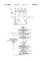
- FIG. 1illustrates a communication system 10 that provides both telephone and data service to a subscriber 12.
- a station 14is coupled to subscriber 12 using subscriber line 16.
- station 14provides telephone service, data service, or both telephone and data service to subscriber 12 using subscriber line 16.
- Subscriber line 16may support simultaneous telephone and data service using twisted pair wiring.
- Subscriber 12includes a telephone 20 and a computer 22, both coupled to an interface 24.
- a splitter 25is coupled to subscriber line 16 and operates to split subscriber line 16 into a twisted pair phone line 26 and a twisted pair data line 28.
- Phone line 26is coupled to telephone 20 using interface 24.
- data line 28is coupled to computer 22 using interface 24.
- Subscriber 12refers to one or more components at the subscriber premises shown in FIG. 1, as well as the user of these components.
- Telephone 20is a traditional telephone transceiver, a cordless telephone transceiver, or any other device suitable for allowing communication over telephone line 26.
- Computer 22comprises a mainframe device, mini-frame device, server, desktop personal computer, notebook personal computer, or other suitable computing device having an XDSL modem 30 that communicates data using data line 28.
- Modem 30couples to other components of computer 22 using a Peripheral Component Interconnect (PCI) bus, an Industrial Standard Architecture (ISA) bus, a Personal Computer Memory Card International Association (PCMCIA) interface, or any other suitable technology that provides input/output capability to computer 22.
- PCIPeripheral Component Interconnect
- ISAIndustrial Standard Architecture
- PCMCIAPersonal Computer Memory Card International Association
- the selection and design of modem 30 for computer 22may depend on the type or functionality of computer 22, as well as the data service rate supported by data line 28.
- Modem 30transmits and receives data in communication system 10 using any suitable digital subscriber line technology, referred to generally as XDSL.
- Modem 30also supports Ethernet, Fast Ethernet, V.35 data protocol, frame relay, asynchronous transfer mode (ATM), switched multi-megabit data service (SMDS), high-level data link control (HDLC), serial line Internet protocol (SLIP), point-to-point protocol (PPP), transmission control protocol/Internet protocol (TCP/IP), or any other appropriate protocol, collectively referred to as digital protocol.
- computer 22may include a network interface 31 to receive data from station 14 or to further communicate data to a local area network (LAN), wide area network (WAN), or other suitable network coupled to computer 22 using link 18.
- modem 30translates information between the communication protocol supported by communication system 10 and the digital protocol supported by computer 22.
- Communication system 10includes numerous other twisted pair subscriber lines 16 coupled to other subscribers 12.
- station 14comprises a central office or other device in the public switched telephone network (PSTN) that provides phone and data service to a number of subscribers, with each subscriber 12 including one or more components described above at its premises.
- PSTNpublic switched telephone network
- the subscribers and subscriber lines in communication system 10are referred to collectively in the plural as subscribers 12 and subscriber lines 16.
- Interface 24couples phone line 26 to telephone 20, and data line 28 to computer 22. In one embodiment, interface 24 provides additional couplings to additional telephones 20 and computers 22 at subscriber 12.
- Splitter 25is a passive or active splitter that divides subscriber line 16 into phone line 26 and data line 28 of the same type. Throughout this description, phone line 26 and data line 28 may be referred to specifically, or collectively as part of subscriber line 16.
- Subscriber line 16couples subscriber 12 to station 14. Subscriber line 16 comprises twisted pair wiring that is commonly installed at subscriber premises and as the local loop in many public switched telephone networks (PSTNs). Subscriber line 16 may be unshielded twisted pair (UTP), shielded twisted pair (STP), or other suitable type or category of twisted pair wiring made of copper or other suitable material. Phone line 26 and data line 28 associated with subscriber line 16 may be the same or different type or category of twisted pair wiring.
- PSTNspublic switched telephone networks
- UTPunshielded twisted pair
- STPshielded twisted pair
- Phone line 26 and data line 28 associated with subscriber line 16may be the same or different type or category of twisted pair wiring.
- Station 14includes an optional splitter 50 coupled to subscriber line 16. Like splitter 25 at subscriber 12, splitter 50 at station 14 is a passive or active splitter that divides subscriber line 16 into a twisted pair phone line 52 and a twisted pair data line 54. Phone line 52 and data line 54 associated with subscriber line 16 may be the same or different type or category of twisted pair wiring.
- a telephone switch 56 at station 14is coupled to phone line 52 to provide plain old telephone system (POTS) service to subscriber 12.
- POTSplain old telephone system
- Telephone switch 56also represents other components in the PSTN or other suitable voice communication network, such as switches, wireline or wireless links, satellites, microwave uplinks, and other communication facilities to deliver telephone service to subscriber 12.
- a communication server 58is coupled to splitter 50 using data line 54. As described in detail below, communication server 58 manages the provisioning of data service to subscriber 12. Communication server 58 performs off-hook detection on the local loops formed by subscriber lines 16 to determine if subscriber 12 desires data service. Specifically, communication server 58 couples a modem to subscriber line 16 upon detecting a need for data service from computer 22. Communication server 58 tracks subscriber usage, monitors subscriber information, and generates billing and demographic information, as described below.
- the data off-hook detector in communication server 58can use one of several methods to determine whether subscriber 12 should be connected to an XDSL modem.
- the off-hook detectormay monitor direct current voltages, electrical tones, data link frames, or any other protocol or data sequencing to determine whether subscriber 12 needs data access.
- the off-hook detector in communication server 58may monitor electrical tones generated by modem 30 while in the process of training, notching, equalizing, or performing any other task that puts electrical tones onto subscriber line 16 and its associated data line 54.
- Communication server 58may also detect frames or packets. These frames or packets could be Ethernet, ATM, HDLC, or any suitable data communications frame format.
- the off-hook detector in communication server 58could also examine various protocols such as TCP/IP, PPP, or any other suitable network protocol or data stream.
- Communication server 58multiplexes modem digital outputs into a multiplexed digital line 62 for delivery to a router or other network device 60.
- multiplexed digital line 62carries a single bidirectional and multiplexed signal for all subscribers 12 in communication system 10. Signals on multiplexed digital line 62 may support any appropriate digital protocol used by network device 60.
- a communication network 64such as a global communication network like the Internet, is coupled to network device 60.
- Communication network 64may also include a synchronous optical network (SONET), a frame relay network, an asynchronous transfer mode (ATM) network, a T1, T3, E1, or E3 network, or any other suitable communication network.
- SONETsynchronous optical network
- ATMasynchronous transfer mode
- Communication server 58may couple to the same number and type of data lines 54 as represented by subscriber lines 16 in communication system 10. For example, if station 14 services one thousand subscribers 12 using twisted pair subscriber lines 16, then data lines 54 coupled to communication server 58 may represent as many as one thousand twisted pair lines.
- splitter 50need not provide a separate data line 54 for those subscribers 12 that only desire phone service from telephone switch 56. As more subscribers 12 desire access to data service, the XDSL communication capabilities of splitter 50 and communication server 58 may be supplemented in a modular and cost effective manner to meet the demand.
- Communication system 10supports data service over subscriber lines 16 using asymmetric digital subscriber line (ADSL), symmetric digital subscriber line (SDSL), high-speed digital subscriber line (HDSL), very high-speed digital subscriber line (VDSL), or any other suitable technology that allows high rate data service over twisted pair wiring that forms the local loops to subscribers 12. All of these technologies are referred to collectively as XDSL or communication protocol.
- ADSLsymmetric digital subscriber line
- SDSLsymmetric digital subscriber line
- HDSLhigh-speed digital subscriber line
- VDSLvery high-speed digital subscriber line
- XDSLcommunication protocol
- subscriber line 16 and components of subscriber 12 and station 14support communication using ADSL techniques that comply with ANSI standard T1.413.
- ADSL communication over subscriber line 16may be performed using the carrier-less amplitude phase modulation (CAP) technique developed by AT&T Corporation.
- CAPcarrier-less amplitude phase modulation
- the downlink data rate 32 from station 14 to subscriber 12is greater than the uplink data rate 34 from subscriber 12 to station 14. This allows high bandwidth communication to subscriber 12, while still providing lower bandwidth communication to station 14.
- ADSL communicationis well-adapted for applications, such as video-on-demand, multimedia, and Internet access, that transfer large volumes of information to subscriber 12 in response to shorter requests for information.
- downlink data rate 32is approximately 1.5 Mbps
- uplink data rate 34is approximately 750 kbps.
- downlink data rate 32may be six Mbps or more depending on the specific XDSL technology employed, the quality and length of subscriber line 16, and the contribution of noise and distortion from other components in communication system 10.
- local loops formed by subscriber lines 16may have a maximum length imposed by the XDSL modulation technique or hardware.
- XDSL modulation technique or hardwareFor example, an existing ADSL implementation operates over local loops of 12,000 feet or less.
- the present inventioncontemplates, expects, and specifically includes additional communication technologies that extend the maximum length, bandwidth, and quality of communication between subscribers 12 and station 14.
- XDSL technologyprovides data service using existing subscriber lines 16 without interrupting normal telephone service. This is accomplished by a separation technique, such as frequency division multiplexing (FDM), to separate frequencies that provide telephone service from those frequencies that provide data service. Dynamic noise cancellation techniques and a guard band between the data and phone service frequencies ensure reliable and simultaneous access to data and phone service over subscriber line 16. For example, subscriber 12 may simultaneously engage in both a data communication session using computer 22 and a voice conversation using telephone 20.
- FDMfrequency division multiplexing
- communication system 10provides phone and data service to subscriber 12. Subscriber 12 accesses phone service by using telephone 20 to initiate a call. Upon going off-hook, communication system 10 establishes a circuit between telephone 20 and telephone switch 56 using interface 24, phone line 26, splitter 25, subscriber line 16, splitter 50, and one of phone lines 52. Upon establishing this telephone circuit, subscriber 12 using telephone 20 receives POTS service from telephone switch 56.
- modem 30repetitively transmits the need for data service in a request interval, where the request interval comprises the time length of the request and the silent interval until the next request.
- the need for data service indicated at subscriber 12may be based on the establishment of a closed circuit between subscriber 12 and station 14 or on one or more analog or digital signal transitions.
- Modem 30communicates the need to communication server 58 at station 14 using interface 24, data line 28, splitter 25, subscriber line 16, splitter 50, and one of data lines 54.
- communication server 58detects the need for data service and selects an XDSL modem at communication server 58 to communicate with XDSL modem 30 in computer 22.
- subscriber 12engages in a data communication session with communication network 64 using network device 60.
- computer 22may function as a gateway into communication network 10 for other devices coupled to network interface 31 using link 18.
- splitter 50, communication server 58, and network device 60are located at a central office of the PSTN to provide an efficient and modular provisioning of XDSL data service and voice service to subscribers 12.
- communication server 58 and network device 60may be located at a central office, end office, remote terminal, private premises, or any other location that provides a point of presence of network 64.
- Splitter 50, communication server 58, and network device 60may be located at any site or sites remote from subscribers 12 without departing from the scope of the present invention.
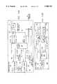
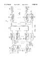
- FIG. 2illustrates in more detail communication server 58.
- Data lines 54 associated with subscriber lines 16are coupled to a switch 70.
- each data line 54corresponds to an associated subscriber line 16 and its related subscriber 12.
- Switch 70couples selected data lines 54 to output lines 72 that in turn couple to modem pool 74.
- the format of signals on data lines 54 and output lines 72is the same as the format of signals on subscriber lines 16. For example, if communication system 10 adopts XDSL technology, signals on data lines 54 and output lines 72 are modulated using XDSL techniques.
- Modems in modem pool 74convert signals in an appropriate XDSL communication protocol into digital data in an appropriate digital protocol on digital lines 76.
- a multiplexer 78is coupled to digital lines 76 and combines the signals on digital lines 76 into a fewer number of multiplexed digital lines 62. In one embodiment, multiplexer 78 combines information for delivery to network device 60 using a single multiplexed digital line 62.
- a controller 80is coupled to data lines 54 using a link 82. Controller 80 is also coupled to switch 70 and modem pool 74 using links 84 and 86, respectively. Controller 80 detects a need for data service generated by subscribers 12 and communicated over subscriber lines 16 to data lines 54. In response, controller 80 using link 84 directs switch 70 to couple a selected subset of data lines 54 to selected output lines 72 that couple to modems in modem pool 74. For example, controller 80 may monitor one thousand data lines 54 to provide XDSL data services using one hundred modems in modem pool 74.
- Controller 80also receives information from modem pool 74 using link 86 to determine status information of modems in modem pool 74. As digital lines 76 become inactive for a predetermined period of time, modem pool 74 detects this inactivity and generates a timeout indication for communication to controller 80. Upon receiving the timeout indication, controller 80 releases the inactive modem in modem pool 74 for later use.
- communication server 58detects a need for data service on a selected data line 54. This need may be indicated by current voltages, electrical tones, data link frames, packets, or any other suitable analog or digital protocol or data sequencing. Controller 80 detects the need using link 82 and configures switch 70 to provide a coupling between the selected data line 54 and one of the output lines 72 coupled to a selected modem pool 74. The selected modem translates bidirectional communication between a communication protocol on output line 72 and a digital protocol on digital line 76. Multiplexer 78 translates information between digital lines 76 and one or more multiplexed digital lines 62.
- FIG. 3illustrates in more detail controller 80.
- Data lines 54 through link 82are coupled to polling circuitry 100.
- polling circuitry 100includes a number of terminals 102 corresponding to each data line 54.
- a switch 104 having a conductive probe 106contacts terminals 102 to sample the signal on the associated data line 54.
- Polling circuitry 100may comprise electromagnetic components, such as a relay or switch, solid state circuitry, or both. It should be understood that the present invention embodies any polling circuitry 100 that allows sampling, in succession or simultaneously, one or more data lines 54.
- Transceiver 108receives a selected signal 110 from polling circuitry 100.
- a detector 112is coupled to transceiver 108, which in turn is coupled to processor 116.
- Detector 112may include a media access controller (MAC) and associated memory to detect and store frames or packets of an appropriate digital protocol. Detector 112 may also include less complicated circuitry to detect current voltages, electrical tones, data bit transmissions, or other analog or digital information generated by transceiver 108.
- MACmedia access controller
- Transceiver 108 and detector 112may collectively be represented as modem 115, as indicated by the dashed line.
- Modem 115provides an interface between the XDSL communication protocol of communication system 10 and processor 116.
- Modem 115also includes similar components and performs similar functions as modem 30 in computer 22 to enable modem 30 and modem 115 to exchange information using XDSL technology.
- the term detectormay refer to detector 112 or collectively modem 115.
- a processor 116is coupled to detector 112 and controls the overall operation of controller 80.
- a timer 117is coupled to processor 116.
- Processor 116is coupled to input/output circuitry 118, which in turn is coupled to switch 70 and modem pool 74 using links 84 and 86, respectively.
- Processor 116is also coupled to switch 104 of polling circuitry 100 using input/output circuitry 118.
- processor 116controls the data line selection, dwell time, and other suitable parameters of polling circuitry 100.
- Database 120stores information as one or more tables, files, or other data structure in volatile or non-volatile memory. All or a portion of database 120 may reside at controller 80, within communication server 58, within station 14, or at another location in communication system 10. For example, several communication servers 58 in one or more central offices or other devices of communication system 10 can access database 120 stored in a central location to provide more intelligent management and provisioning of XDSL data service in communication system 10. One or more stations 14 may be coupled together and the resources of their associated communication servers 58 shared using simple network management protocol (SNMP) techniques.
- SNMPsimple network management protocol
- Program 121contains instructions to be executed by processor 116 to perform the functions of controller 80.
- Program 121may reside in database 120 as shown or may be integral to memory components in transceiver 108, detector 112, and/or processor 116.
- Program 121may be written in machine code, pseudocode, or other appropriate programming language.
- Program 121may include modifiable source code and other version control features that allow modification, debugging, and enhancement of the functionality of program 121.
- Activity table 122maintains status information on data lines 54, switch 70, and output lines 72.
- activity table 122contains information on inactive and active data lines 54, data lines 54 corresponding to current valid subscribers 16 of XDSL data service, and the mapping performed by switch 70 between data lines 54 and output lines 72.
- activity table 122includes information that specifies the inactivity of a modem in modem pool 74, the status of a data line 54 as dedicated, and any other suitable information that enables processor 116 to monitor and control the operation of switch 70 and modem pool 74.
- Profile table 124stores profile information on data lines 54. This profile information reflects electrical or physical characteristics of data line 54, its associated subscriber line 16 and data line 28, intervening components such as interface 24, splitter 25, splitter 50, and polling circuitry 100, as well as any other component or factor that effects the performance or electrical characteristics of signals received on data lines 54.
- Processor 116may access profile table 124 and provide profile information to transceiver 108 using link 125. Alternatively, transceiver 108 may be a more robust and broadband device that does not need profile information from profile table 124. Processor 116 may also provide profile information to program XDSL modems in modem pool 74 once a coupling is made to a selected data line 54.
- the existence and complexity of profile information in profile table 124depends on the requirements of transceiver 108 and XDSL modems in modem pool 74, as well as the complexity of signals that indicate a need for data service from subscriber 12.
- Subscriber table 126stores subscriber information indexed by one or more identifiers of subscriber 12, computer 22, modem 30, subscriber line 16, or other information that associates data line 54 with a particular subscriber 12. Subscriber table 126 includes subscriber connect times, session duration, session activity, session logs, billing data, subscriber account information, and any other suitable subscriber information. This information may be summarized and additional information included to generate billing and demographic data on subscribers 12 in communication system 10.
- subscriber table 126may maintain summary statistics on the number of subscribers 12 served by communication server 58, the average connect time, load factors, time-of-day connection profiles, and other statistics to assess the communication facilities to be deployed at communication server 58, the over-subscription ratio that can be supported by communication system 10, and other provisioning and management issues. Furthermore, subscriber table 126 may combine subscriber information from one or more communication servers 58 in one or more stations 14 in communication system 10.
- Management interface 128is coupled to processor 116 and database 120 and allows external access to the functionality of processor 116. Management interface 128 is also coupled to database 120, which allows modification of program 121, as well as remote access and modification of information in activity table 122, profile table 124, and subscriber table 126.
- the telephone service provider or other entity that operates station 14 or communication system 10accesses management interface 128 to provide management and control over the operations of controller 80 and communication server 58.
- the telephone service provideruses management interface 128 to access activity table 122 and/or subscriber table 126 to update the valid subscribers 12 that have access to communication server 58.
- a local or remote computer 130is coupled to program interface 128 using an appropriate data link 132, such as a serial RS-232 link, to provide this management feature.
- modem 30 in computer 22indicates a need for data service, and communicates this need to an associated data line 54 using interface 24, data line 28, splitter 25, subscriber line 16, and splitter 50.
- modem 30transmits successive requests at a predetermined request interval.
- Processor 116accesses activity table 122 to determine which data lines 54 to poll, depending on the active or inactive status of the data line 54, whether subscriber 12 corresponding to data line 54 is a current and valid subscriber, and other appropriate considerations.
- activity table 122may indicate valid and non-dedicated subscribers 12 to poll.
- Polling circuitry 100successively or simultaneously polls one or more selected data lines 54, as directed by processor 116, using link 82 to detect a need for data service. For each data line 54 polled, processor 116 may access profile table 124 in database 120 and provide associated profile information to transceiver 108 using link 125. Polling circuitry 100 dwells on each data line 54 for a predetermined polling interval to detect a need. In one embodiment, the polling interval is at least two times a request interval of modem 30.
- transceiver 108may translate the information from the selected XDSL communication protocol employed on subscriber line 16 into digital or analog data for detection by detector 112.
- a media access controller (MAC) in detector 112may transform serial digital data from transceiver 108 into a parallel digital format.
- Detector 112receives the information translated by transceiver 108, and stores this information in a suitable memory location for access by processor 116.
- Processor 116periodically accesses detector 112 to determine if a need for data service has been detected.
- processor 116Upon detecting a need for data service, processor 116 accesses database 120 to determine the availability and status of modems in modem pool 74. Processor 116 selects an available modem from modem pool 74. Processor 116 then directs switch 70 to make the appropriate coupling between selected data line 54 and output line 72 coupled to the selected modem. Upon establishing coupling between modem 30 in computer 22 at subscriber 12 and a selected modem in modem pool 74, controller 80 continues to monitor the remaining data lines 54 using polling circuitry 100.
- Processor 116can transmit status or connection information to modem 30 in computer 22 using transceiver 108. This may be performed before, during, or after coupling the selected modem in modem pool 74 to data line 54. For example, processor 116 may send acknowledgment information to modem 30 that includes an indication that a modem is or is not available, an identification of the available modem, a time interval before modem 30 should attempt communication with the selected modem in modem pool 74, or any other suitable information. Furthermore, processor 116 may access information from subscriber table 126, such as billing and account information, historical connection information, or other suitable subscriber information, and transmit this information separate to or as part of the acknowledgment information described above.
- subscriber table 126such as billing and account information, historical connection information, or other suitable subscriber information
- Processor 116may also transmit connection information and updated billing and subscriber information to modem 30 at computer 22 using link 86 and the associated XDSL modem in modem pool 74. This information may include the length of the current session, the current balance in the account of subscriber 12, as well as any other suitable information that relates to the account or activity of subscriber 12 with communication server 54. Generally, processor 116 may communicate any suitable information stored at or made available to controller 80 to subscribers 12 using transceiver 108 or the associated modem in modem pool 74.
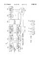
- FIG. 4illustrates in more detail switch 70 and modem pool 74 of communication server 58.
- Data lines 54are coupled to switch 70, now shown in more detail as a cross-bar or cross-point matrix switch.
- data lines 54correspond to lines 150
- output lines 72correspond to lines 152 in switch 70.
- the number of lines 150 (n)is greater than the number of lines 152 (m).
- switch 70couples the second of lines 150 to the last of lines 152 by establishing connection 154.
- switch 70couples the last of lines 150 and the first of lines 152 by establishing connection 156.
- switch 70is shown in FIG. 4 to be a cross-bar or cross-point matrix switch, it should be understood that any device that can couple a number of data lines 54 to a reduced number of output lines 72 may be used.
- Switch 70may incorporate electromagnetic components, such as relays and contacts, or may be implemented in whole or in part using one or more solid state devices.
- Modem pool 74includes XDSL modems 160 associated with output lines 72 from switch 70. Modems 160 translate information between an appropriate XDSL communication protocol on output lines 72 and an appropriate digital protocol on digital lines 76.
- modems 160may be similar in construction and operation to modem 30 at subscriber 12.
- a detector 162 coupled to modems 160detects the activity of modems 160 to determine if the line has become inactive for a predetermined interval of time. For example, if one of the modems 160 does not display activity over a five-minute interval, detector 162 generates a timeout indication to notify processor 116 of the inactive modem. Processor 116 releases or decouples the inactive modem for later subscriber sessions.
- detectors 162may include one-shot timers or other retriggerable timers set for a predetermined time interval to detect the inactive status of modems 160.
- Detector 162is a monitoring circuit that passes through the digital output of modems 160 to digital lines 76 for presentation to multiplexer 78.
- Multiplexer 78may combine signals from digital lines 76 into a single multiplexed digital line 62. Alternatively, multiplexer 78 may employ any suitable reduction ratio that places signals on digital lines 76 on a fewer number of multiplexed digital lines 62.
- Processor 116may directly communicate with modems 160 using link 164.
- link 164allows processor 116 to program modems 160 with profile information retrieved from profile table 124.
- Link 164also supports communication between processor 116 and selected subscribers 12 during an active subscriber session using modems 160.
- link 164allows processor 116 to monitor the information received from and transmitted to subscribers 12 during a communication session.
- switch 70couples a selected subset of data lines 54 to output lines 72 in response to signals received from controller 80 using link 84.
- Each of the output lines 72is coupled to an associated modem 160 which translates the information formatted in an analog communication protocol, such as XDSL, into an appropriate digital signal.
- the digital information output from modems 160passes through detector 162, which monitors the activity on the output line of modems 160. If detector 162 senses inactivity over a predetermined interval, a timeout indication is provided to processor 116 using link 86. Signals on digital lines 76 may be reduced to fewer multiplexed digital lines 62 using multiplexer 78.
- FIG. 5illustrates in more detail transceiver 108 in controller 80.
- transceiver 108includes filters and magnetics 170 to condition the signal from selected data line 54. The conditioned signal is provided over differential lines 172 to analog bit pump 174.
- Bit pump 174performs the specific demodulation technique for the chosen XDSL communication protocol. For example, bit pump 174 may execute a discrete multi-tone demodulation (DMT) or carrierless amplitude phase demodulation (CAP) to demodulate an XDSL signal on differential lines 172 into a digital stream on line 176.
- DMTdiscrete multi-tone demodulation
- CAPcarrierless amplitude phase demodulation
- Logic and timing circuitry 178contains decode logic, timing and synchronization circuitry, steering logic, and other appropriate digital processing circuitry to produce a data signal on receive data line 180 and a corresponding clock signal on clock line 182 for delivery to detector 112 or processor 116.
- Detector 112may include a MAC to support any digital protocol or signal detection that indicates a need for XDSL data service.
- the datamay be in non-return-to-zero format or any other suitable format.
- transceiver 108receives a data signal on transmit data line 184 from detector 112 or processor 116. Using the clock line 182, logic and timing circuitry 178 digitally processes signals received on transmit data line 184 for delivery to analog bit pump 174. Using an appropriate modulation technique, such as DMT or CAP, analog bit pump 174 produces an analog signal for delivery over differential lines 172 to filters and magnetics 170 for transmission over selected data line 54.
- an appropriate modulation techniquesuch as DMT or CAP
- FIG. 6illustrates in more detail a specific embodiment of detector 112 that includes a MAC 113 and a memory 114.
- MAC 113is coupled to receive data line 180 and clock line 182, and translates received data from a serial data format, such as a non-return-to-zero format, into an appropriate parallel digital format.
- MAC 113translates the data from the chosen digital protocol and provides the data to memory 114 using data bus 190.
- MAC 113also provides an address to memory 114 using address bus 192 to specify the location in memory 114 to store data provided on data bus 190.
- MAC 113provides a write signal to memory 114 using control line 194.
- MAC 113To transmit data, MAC 113 provides a read signal to memory 114 using control line 194, and an associated address of the data to be read using address bus 192. In response, memory 114 provides the requested data on data bus 190. MAC 113 translates the data into the selected digital protocol for placement on transmit data line 184.
- FIG. 7illustrates one embodiment of activity table 122 stored in database 120 of controller 80.
- Processor 116accesses and modifies entries in activity table 122 to direct the operation of controller 80.
- management interface 128provides external access to activity table 122. For example, a telephone service provider using management interface 128 can add, delete, or otherwise modify entries in activity table 122 to maintain a listing of valid subscribers 12.
- Database 120stores some or all of the status information shown in this exemplary activity table 122, as well as other information that may be used by processor 116 to direct the activities of controller 80.
- Activity table 122includes a data line column 200 that contains an address or other appropriate identifier of data lines 54 associated with subscriber lines 16 and their related subscribers 12.
- Status column 202indicates the status of data line 54 identified in data line column 200.
- status column 202may contain one or more indications that the associated data line 54 is inactive (I), active (A), or dedicated (D).
- a timeout column 204indicates whether detector 162 in modem pool 74 has detected a timeout associated with a particular data line 54.
- a modem column 206includes an identifier of the modem 160 associated with the corresponding data line 54.
- An entry in activity table 122corresponds to a row that designates a selected data line 54 in data line column 200, the status of the selected data line 54 in status column 202, a timeout indication of the selected data line 54 in timeout column 204, and the modem associated with the selected data line 54 in modem column 206.
- entry 208relates to data line "D1" which is inactive.
- Entry 210represents data line “D2" which is inactive but dedicated to modem “M1.”
- Entry 212indicates that data line "D4" is active, coupled to modem "M3,” but a timeout indication has been detected.
- Subscribers 12 indicated in status column 202 as dedicatedmay be serviced by communication server 58 in a specific way.
- Switch 70 in communication server 58maintains a coupling between data line 54 corresponding to dedicated subscriber 12 and its associated and dedicated modem 160.
- controller 80need not detect a need for data service or reconfigure the couplings for data line 54 corresponding to dedicated subscriber 12.
- communication server 58provides the option of a different class of service for a dedicated subscriber 12 that desires uninterrupted access to XDSL communication facilities.
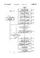
- FIG. 8is a flow chart of a method performed at controller 80 to couple data lines 54 to modems 160 in modem pool 74.
- the methodbegins at step 300 where processor 116 of controller 80 loads activity table 122 from database 120 which contains an entry for each valid subscriber 12 served by communication server 58.
- a telephone service providermay ensure that activity table 122 reflects valid subscribers 12 by monitoring past due accounts, the overuse of data service, successive invalid attempts to access communication server 54, or other factors that may cause subscribers 12 to be invalid.
- Processor 116selects the first inactive and non-dedicated data line 54 indicated by the designation "I" in status column 202 of activity table 122. Since switch 70 is configured to continuously couple dedicated subscribers 12 to their dedicated modems 160, processor 116 need not select an inactive data line 54 that is also dedicated, as indicated by the designation "I/D" in status column 202.
- processor 116uses input/output circuitry 118 to direct switch 104 of polling circuitry 100 to couple transceiver 108 to the selected inactive and non-dedicated data line 54 at step 304. If appropriate, processor 116 accesses profile table 124 in database 120 and provides profile information for the selected data line 54 to transceiver 108 using link 125 at step 306. Processor 116 initializes timer 117 with a predetermined polling interval at step 308.
- processor 116checks timer 117 at step 314. If the polling interval monitored by timer 117 has not expired at step 314, then processor 116 again determines if a need has been detected at step 312. However, if the polling interval monitored by timer 117 has expired at step 314, processor 116 selects the next inactive and non-dedicated data line 54 as indicated in status column 202 of activity table 122 at step 316, and returns to step 304.
- the associated informationmay be further processed by detector 112 and placed in memory for access by processor 116 at step 318.
- transceiver 108, detector 112, and/or processor 116may validate the need for data service. Validation may be performed at a low level, such as a verification of the checksum or detection of an incomplete transmission, or at a higher level, such as a verification of an identifier, password, or other security information that provides access to communication server 58. Validation contemplates any level of validation or security handshake that confirms that the received need is valid and accepted by controller 80.
- processor 116Upon selecting an unused modem at step 332, processor 116 generates a command that directs switch 70 to couple the selected data line 54 to the selected modem 160 at step 333.
- Processor 116may communicate status or connection information to subscriber 12 using transceiver 108 or the selected modem 160 at step 334.
- Processor 116updates activity table 122 at step 336 to indicate that the selected data line 54 is now active and that the selected modem 160 is now being used.
- Processor 116directs activity detector 162 to initialize the inactivity interval for the selected modem 160 at step 338.
- Processor 116selects the next inactive and non-dedicated data line 54 in activity table 122 at step 316, and returns to step 304.
- FIG. 9is a flow chart of a method for monitoring and decoupling modems 160 due to inactivity. It should be understood that the methods described with reference to FIGS. 8 and 9 may be performed simultaneously or in alternative succession by processor 116 to couple and decouple data lines 54 with modems 160.
- the methodbegins at step 400 where processor 116 loads activity table 122 which contains an entry for each valid subscriber 12 served by communication server 58.
- Processor 116selects a first active and non-dedicated data line 54 as indicated by the designation "A" in status column 202 of activity table 122 at step 402. Since switch 70 is configured to maintain a coupling between dedicated subscribers 12 and their dedicated modems 160, processor 116 need not select an active data line 54 that is also dedicated, as indicated by the designation "A/D" in status column 202.
- Processor 116retrieves timeout status for modem 160 associated with the selected active data line 54 from detector 162 using link 86 and input/output circuitry 118 at step 404. Processor 116 determines if a timeout has occurred for the selected active data line 54 at step 408. If a timeout has not occurred, processor 116 selects the next active and non-dedicated data line 54 as indicated in status column 202 of activity table 122 at step 410, and returns to step 404.
- processor 116may communicate status or connection information to subscriber 12 associated with the selected active data line 54 using transceiver 108 or the associated modem 160 at step 412.
- Processor 116generates a command to direct switch 70 to decouple the active data line 54 from its associated modem 160 at step 414.
- Processor 116updates activity table 122 at step 416 to indicate that data line 54 is now inactive and that the associated modem 160 is available for another subscriber session.
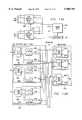
- FIG. 10Aillustrates another implementation of communication server 58 in communication system 10.
- Communication server 58 of FIG. 10Aprovides switching at an isolated four-wire interface.
- data lines 54are coupled to and received by a plurality of line interface units 500.
- Each line interface 500provides an analog interface, line driver and transformer for processing signals on data lines 54.
- Each line interface unit 500is coupled to a switching matrix 502 and communicates with switching matrix 502 across a transmit data pair 504 and a receive data pair 506.
- Each line interface unit 500operates to interface between transmit data pair 504 and receive data pair 505 and twisted pair data line 54.
- a detector 508is coupled to each receive data pair 506. Each detector 508 operates to detect a request for service on the associated receive data pair 506 and, upon detection, provides a signal to controller 80 indicating a request for service. Detector 508 is shown in more detail in FIG. 10D, and implementations of detectors are shown in more detail in FIGS. 11A, 11B and 11C. It should be understood that other implementations can combine polling with multiple detectors to reduce the number of inputs to controller 80 and to reduce the number of detectors. For example, FIG. 3 shows an implementation using polling circuitry 100 that can be used with the detector in the communication server embodiment of FIG. 10A.
- switching matrix 502is coupled to a modem pool 510 and communicates with modem pool 510 across transmit data pairs 512 and receive data pairs 514. Transmit data pairs 512 and receive data pairs 514 contain a number of pairs equal to the number of modems in modem pool 510.
- modems in modem pool 510convert signals in an appropriate XDSL communication protocol into digital data in an appropriate digital protocol on digital lines 76.
- Multiplexer 78is then coupled to digital line 76 and provides a multiplexed digital line output 62.
- controller 80provides switch control signals 84 to switching matrix 502 and communicates modem selection and control information 86 with modem pool 510.
- each detector 508detects a request for service on the associated receive data pair 506 and informs controller 80 that a request for service has occurred. Controller 80 then checks which modems in model pool 510 are assigned and which data lines 54 are valid. Controller 80 assigns a modem from modem pool 510 to the requesting data line 54 using switching matrix 502 to connect the associated receive data pair 506 and transmit data pair 504 to the appropriate receive data pair 514 and transmit data pair 512.
- a technical advantage of providing switching at a four-wire interface within communication server 58is that switching matrix 502 is isolated from data lines 54 and subscriber lines 16 by transformers in line interface units 500. Because of this isolation, switching matrix 502 can operate without constraints imposed by technical requirements for interaction with data lines 54 and subscriber lines 16. For example, the isolation of switching matrix 502 allows CMOS switches to be used rather than more expensive solid state relays or mechanical relays.
- FIG. 10Billustrates in more detail line interface device 500 of communication server 58 of FIG. 10A.
- Line interface device 500includes a line protection circuit 520 that is coupled to and receives data line 54.
- Line protection circuit 54operates to ensure that activity down stream in communication server 58 does not affect the integrity of data line 54.
- Line protection circuit 520is coupled to a magnetics/hybrid unit 522.
- Magnetics/hybrid unit 522can comprise a transformer and operates to interface between the data line and an internal transmit data pair 524 and receive data pair 526. Magnetics/hybrid unit 522 also isolates the four-wire interface provided by internal receive data pair 526 and transmit data pair 524 from data line 54.
- a line receiver 528receives receive data pair 526 and drives signals to a receive filter 530.
- the output of receive filter 530is receive data pair 506 which is coupled to switching matrix 502 as shown in FIG. 10A.
- transmit data pair 504is coupled to a transmit filter 532 which provides signals to a cable driver 534. Cable driver 534 then drives signals on transmit data pair 524 to magnetics/hybrid unit 522.
- FIG. 10Cillustrates in more detail controller 80 of communication server 58 where a plurality of detectors provide indications of a request for service.
- Controller 80 of FIG. 10Cincludes processor 116 and input/output circuitry 118 as discussed above with respect to FIG. 3.
- Controller 80also includes a scanner or processor interrupt circuit 540 which receives the request for service indications from detectors 508 and provides a scanner output or processor interrupt to processor 116. This allows the outputs of a number of detectors 508 to be sampled to provide an appropriate signal to processor 116 when a request for service has been detected.
- scanner or processor interrupt circuit 540comprises a gate array having logic circuitry for generating appropriate interrupt signals to processor 116.
- FIG. 10Dillustrates in more detail a detector 508 of communication server 58.
- detector 508includes a receiver circuit 550 and a service request detector 552.
- Receiver circuit 550is coupled to a receive data pair 506 and provides an output to service request detector 552.
- Service request detector 552then operates to identify a request for service.
- service request detector 552provides a signal indicating a request for service to controller 80.
- the request for servicecan be an initial tone that is a pure sinusoid or a modulated sinusoid.
- FIGS. 11A, 11B and 11CThree implementations of a detector 508 are illustrated in more detail in FIGS. 11A, 11B and 11C and described below.
- FIG. 10Eillustrates in more detail a modem 560 in modem pool 510 of communication server 58.
- Modem 560is analogous to modem 108 of FIG. 5 with filters and magnetics 170 removed.
- Modem 560includes a bit pump 174 which communicates with switching matrix 502 across receive data pair 526 and transmit data pair 524.
- Modem 560does not need to include filters and magnetics 170 because of the functions provided by line interface units 500 to create the four-wire interface described above.
- Bit pump 174 and logic and timing circuitry 178otherwise operate as discussed with respect to FIG. 5.
- the implementation of FIG. 10Amoves the function of filters and magnetics 170 of modem 108 to line interface units 500 to isolate switching matrix 502 from data lines 54.
- FIG. 11Aillustrates in more detail an analog filter implementation of a detector 508 of communication server 58.
- Detector 508 of FIG. 11Adetects the tone or modulated tone using an analog filter circuit tuned to the distinct frequency used to transmit a subscriber request for service.
- Detector 508comprises a differential receiver 570 that is coupled to an associated receive data pair 506.
- Differential receiver 570is coupled to and provides a signal to a band pass filter 572.
- Band pass filter 572is coupled to a gain device 574 which is coupled to a signal processing circuit 576.
- the output of signal processing circuit 576is coupled to a rectifier circuit 578 which is coupled to a low pass filter 580.
- the output of low pass filter 580is then provided as one input to a voltage comparator 582.
- the other input to voltage comparator 582is connected to a reference voltage 584.
- detector 508operates to detect a tone or modulated tone that indicates a request for service on receive data pair 506.
- Differential receiver 570produces a voltage output which is filtered by band pass filter 572 and provided to gain device 574.
- Gain device 574then amplifies the signal and provides it to signal processing circuit 576.
- the signal processing circuit 576processes or demodulates the XDSL signals generated at the customer location that indicate a request for data service.
- Signal processing circuit 476provides the signal to rectifier circuit 578 that outputs the signal to low pass filter 580.
- Low pass filter 580filters low frequency noise to provide a DC voltage as an input to voltage comparator 582.
- Voltage comparator 582compares that DC voltage with reference voltage 584 and outputs a logic high when the DC voltage is greater than reference voltage 584.
- Reference voltage 584is set so that voltage comparator 582 signals a request for service only when the appropriate tone or modulated tone is present on receiver data pair 506.
- detector 508 of FIG. 11Acan be connected to polling circuit 100 of FIG. 3 or other polling circuits to reduce the number of detectors required or to scan the outputs of the detectors.
- the number of lines that can be polled by a single polling circuitis generally limited by the amount of time that is required by the detector to reliably detect the subscriber request for service.
- FIG. 11Billustrates in more detail a tone decoder implementation of detector 508 of communication server 58.
- Detector 508comprises a differential receiver 590 that is coupled to receive data pair 506 and provides an output to a band pass filter 592.
- Band pass filter 592is coupled to a gain device 594 which provides an output to a signal processing circuit 596.
- the signal processing circuit 576processes or demodulates the XDSL signals generated at the customer location that indicate a request for data service.
- the output of signal processing device 596is then coupled to a tone decoder circuit 598. Tone decoder integrated circuit 598 provides an output to controller 80 indicating a request for service upon detection.
- tone decoder circuit 598comprises an integrated circuit, and specifically is an LMC567 tone decoder available from NATIONAL SEMICONDUCTOR.
- tone decoder circuit 598includes a phase locked loop detector for identifying the tone or modulated tone that indicates a request for service. The phased locked loop detects when the received tone or modulated tone matches the signaling frequency, and the tone detector circuit responds by signaling a request for service.
- FIG. 11Cillustrates in more detail a digital signal processor implementation of detector 508 of the communication server 58.
- Detector 508 of FIG. 11Ccomprises a polling circuit 600 that is coupled to a plurality of receive data pairs 506. Polling circuit selects each receive data pair 506 and connects it to a line receiver 602. Line receiver 602 is coupled to a filter 604 which is coupled to an analog/digital converter 606. Analog/digital converter converts the signal to a digital signal and provides an output to a digital signal processor 608. Upon detection, digital signal processor provides a request for service indication to controller 80.
- polling circuitry 600connects line receiver 602, filter 604, analog/digital converter 606 and digital signal processor 608 to each line in succession.
- Digital signal processor 608reads the data from the analog/digital converter 606 and demodulates or detects the request for service.
- the dwell time for polling circuitry 600can be set, for example, such that detector 508 can poll the lines in less than half the duration of the subscriber request for service tone or modulated tone.
- the number of lines that can be polled by a single digital signal processor 608is then determined by the amount of time required for digital signal processor 608 to reliably perform the detection algorithm and the duration of the tone described above.
- Digital signal processor 608is programmable to detect the subscriber request for service tone or modulated tone using an appropriate tone detection algorithm or demodulation algorithm.
- One advantage provided by the detector implementation of FIG. 11Cis this programmability of the algorithm within digital signal processor 608.
- tones used to indicate service in the above description of FIGS. 11A, 11B, and 11Cmay be the tone used in standard non-switched applications of XDSL modems, or may be additional tones added specifically to facilitate detection in switching.
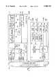
- FIG. 12illustrates in more detail a digital switching matrix implementation of communication server 58.
- the implementation of FIG. 12is appropriate for both a two-wire and four-wire interface to provide digital switching of the modem connections.
- Communication server 58 of FIG. 12includes line interface components and data off-hook detection units 610 that interface with subscriber lines 54 and detect subscriber requests for service. Request for service indications are then provided to controller 612 for controlling the modem connections.
- Each line interface and detection unit 610is coupled to an associated analog/digital and digital/analog converter 614.
- Converters 614are in turn connected to parallel/serial and serial/parallel converters 616.
- Converters 616are coupled to a digital multiplexer 618 which operates under control of controller 612 to connect converters 616 to assigned modems in modem pool 620.
- Modems in modem pool 620are coupled to a network interface/multiplexer 622 and can be implemented using digital signal processors. As shown, network interface/multiplexer 622 is coupled to and communicates with controller 612. This allows network interface/multiplexer 622 to know which modems and lines are active without having to monitor the communication traffic on the lines.
- incoming communicationsare converted to digital words by converters 614 and then converted to serial bit streams by converters.
- the serial bit streamsare connected to an assigned modem by digital multiplexer 618.
- the modems in modem pool 620then communicate with network interface/multiplexer 622.
- Serial bit streams from the modemsare converted to parallel words and then to analog signals for transmission on data lines 54.
- This digital switching implementation of communication server 58can be advantageous for switching of higher frequency XDSL communications.
- FIG. 13Aillustrates in more detail a frequency multiplexing implementation for switching modem connections in communication server 58.
- This frequency multiplexing implementationcould be appropriate for being located at a cable operator as well as a central office of a telephone network.
- data lines 54are coupled to receiver/buffers 630 and transmit/buffers 632.
- Data off-hook detectors 634are coupled to the output of receiver/buffers 630 and provide request for service indications to controller 636.
- communication server 58includes a frequency agile modulator 638 and a frequency agile demodulator 640. Each modulator 638 operates to modulate an incoming analog signal at a selectable frequency.
- the frequencyis set to one of a plurality of frequencies, f1 to fN, equal in number to the number of available modems.
- each demodulator 640operates to demodulate at a selectable frequency where the frequency is set to one of the plurality of frequencies, f1 to fN.
- Associated modulators 638 and demodulators 640are set to operate at the same frequency.
- Modulators 638provide signals to and demodulators 640 receive signals from a mixer 642.
- Mixer 642mixes the signals from modulators 638 and provides the combined signal to demodulators 644.
- Each demodulator 644operates to demodulate the incoming signal at one of the frequencies, f1 to fN, as designated by controller 636.
- Each demodulator 644is coupled to and provides the demodulated signal to an associated modem 648 in the modem pool. By designating the appropriate frequency, controller 636 effectively connects an assigned a modem 648 to a data line 54.
- Each modem 648provides outgoing analog signals to an associated modulator 646 designated to operate at the same frequency as the associated demodulator 644.
- Modulators 646modulate the analog signal and provide the modulated signal to mixer 642.
- Mixer 642combines the modulated signals and provides the combined signal to each demodulator 640.
- Demodulators 640demodulate the combined signal to recover the appropriate analog signal at their selected frequency and provide the demodulated analog signal to transmit/buffers 632 for transmission.
- modems 648are connected to data lines 540 by modulating and demodulating signals at one of the frequencies, f1 to fN.
- FIG. 13Bis a diagram of frequencies, f1 to fN, used in the implementation of FIG. 13A. This results in each of the modems, m1 to mN, being assigned to one of the frequencies, f1 to fN, based upon the frequency for the connected data line 54, as shown.
- modulators 644 and demodulators 646are designated to operate at the frequency of the modulator 638 and demodulator 640 for that data line 54.
- FIG. 14Aillustrates line interface modules (LIM) 650 and modem pool 652 of a distributed switching implementation of communication server 58.
- a controller 653is coupled to line interface modules 650 and to modem pool 652. As shown, a plurality of line interface modules 650 are coupled to the data lines and to modem pool 652. Each line interface module 650 is operable to detect a request for service on the data lines and to connect each of the data lines it receives to each modem in modem pool 652. Controller 653 operates to select a modem from modem pool 652 in response to a detected request for service. Controller 653 then directs the appropriate line interface module 650 to connect the requesting data line to the selected modem.
- LIMline interface modules
- each line interface module 650receives N data lines and includes switches to connect the N data lines to any of the M modems in modem pool 652. In this manner, the switching function is distributed across line interface modules 650 and is scalable as support for more data lines is added.
- the architecture of FIG. 14Acan be used at a two-wire or four-wire interface.
- Line interface modules 650allow switching capabilities to be scalable with the desired number of modems and over-subscription. As an example, one implementation has four data lines connected to each line interface module 650 and thirty-two modems in modem pool 652. For a 10:1 over-subscription, this implementation would use 80 line interface modules 650 for connecting 320 data lines to the 32 modems in modem pool 652. In order to double the number of supported data lines, another 80 line interface modules 650 could be added along with another 32 modems. On the other hand, if a 5:1 over-subscription for 32 modems is desired, 40 line interface modules 650 would be used to service 160 data lines.
- FIG. 14Billustrates in more detail line interface modules 650 and modems 660 in modem pool 652.
- each line interface module 650includes a plurality of line interface units 654 that receive one of the N tip and ring data lines.
- Each line interface device 654includes magnetics 656 and a plurality of switches 658.
- magnetics 656includes a transformer that receives tip and ring lines of the associated data line.
- a T lineis then provided to a plurality of switches 658 for connecting the T line to one of M outgoing lines.
- the M outgoing linesare equal in number to the number of modems 660 in modem pool 652.
- each line interface device 654outputs of each line interface device 654 are connected together so that line interface module 650 has one output line for each modem 660 in modem pool 652 in addition to one output for the R lines. It should be understood that this can be implemented differentially using a pair of switches to switch the modem to the data line, rather than a single switch and a common R line, to enable switching R lines as well.
- Modem pool 652includes a plurality of modems 660 of which only the front-end portion are shown. Each modem 660 receives two lines from line interface modules 650 using magnetics 662. Because of magnetics 656 and magnetics 662, the switching and connections between line interface devices 654 and modems 660 are isolated from the data lines and from the back-end of modems 660. In one implementation, the connections between line interface modules 650 and modems 660 are accomplished on the back plane of a telecommunications chassis, and the line interface modules 650 and modems 660 are implemented as cards that plug into the back plane. In this implementation, a controller communicates with line interface modules 650 and modems 660 to control switching connections to modems 660.
- the communication server of the present inventiondetects a request for data transport service from a subscriber's XDSL modem, XDSL transceiver unit or other customer premises equipment as well as, for example, from a central office multiplexer.
- the detected request for serviceis then used to switch into connection an XDSL transceiver unit located at the central office, remote terminal or other local loop termination point providing, for example, a point of presence for an information service provider (ISP) or corporate network.
- ISPinformation service provider
- the request-for-service detection mechanismallows a large pool of subscribers to be served by a smaller pool of XDSL transceiver units, thereby providing the basis for a cost-effective, massively deployable XDSL service.
- the request for service detectionalso makes fault tolerance possible since no subscriber is required to be dependent upon any specific XDSL transceiver unit in the pool.
- FIG. 15illustrates a functional block diagram of one embodiment of a distributed switching implementation of the communication server, indicated generally at 700.
- Communication server 700also includes line power modules (LPMs) 706 for powering line interface modules 702 and LIM control modules (LCs) 708 for controlling the line interface modules 702.
- Communication server 700further includes XDSL transceiver units (xTU-C's) 710, system controllers (SCs) 712, and network interface modules (NIs) 714.
- communication server 700can include expansion units 716.
- FIG. 15A number of data buses within communication server 700 are shown in FIG. 15.
- Communication server 700 of FIG. 15operates through the use of four major bus systems on a backplane of communication server 700: an analog switching bus 718, a digital serial bus 720, serial management buses 722, and a power bus (not shown in FIG. 15).
- Each of these busescan support redundancy and fault tolerance.
- an analog test bus (ATB)can be present for optional analog path testing
- a protect buscan be present to allow 1:15 or 1:31 equipment protection for 1:1 deployments
- a busy buscan be used to distribute a busy indication to the line interface modules 702.
- the communication serverconsists of a multiplexer chassis, one or more optional POTS filter chassis, and one or more optional line interface module (LIM) chassis.
- XDSL lines that carry a combined POTS/XDSL signal from the customer premisescan be terminated in a POTS filter shelf, which is a passive unit capable of accepting, for example, up to twenty POTS filter modules 704.
- These POTS filter modules 704can contain lightning and power cross protection as well as passive filters which split out any analog POTS connections to the Public Switched Telephone Network (PSTN).
- PSTNPublic Switched Telephone Network
- Four lines, for example,can be terminated by each POTS module 704, giving the POTS filter shelf a maximum capacity, for example, of 80 subscriber terminations.
- the POTS modules 704are not used.
- Line interface modules 702can reside, for example, either in a multiplexer chassis or in a separate LIM chassis.
- the multiplexer chassiscan be capable of supporting up to eight LIM chassis, for a maximum capacity of 640 subscriber lines, or 10:1 oversubscription.
- the LIM chassiscan accept, for example, up to twenty line interface modules 702, with each module 702 terminating four subscriber lines, giving the LIM chassis a capacity of eighty subscribers (at 10:1 oversubscription).
- the line interface modules 702can contain line isolation circuitry, digital service request detection circuitry, and an analog switching matrix which performs the concentration of lines to the pool of available XDSL transceiver units 710.
- the XDSL signals from the line interface modules 702can be connected to XDSL transceiver units via analog switching bus 718.
- the multiplexer chassiscan support, for example, up to thirty two XDSL transceiver unit modules 710, with each module 710 containing two XDSL transceiver units, for a total of sixty four XDSL transceiver units.
- the XDSL transceiver unitscan be organized in two pools of thirty-two terminations each.
- Each transceivercan be connected to analog switching bus 718 carrying XDSL signals from the line interface modules 702.
- Each XDSL port on line interface modules 702can be connected to one of the thirty two XDSL transceiver units in the assigned pool using a set of analog switches resident on the line interface modules 702.
- Two network interface (NI) modules 714can be provided in the multiplexer chassis, allowing a redundant network interface to be installed if desired.
- the XDSL transceiver unit modules 710can be connected to the network interface modules 714 via redundant digital serial point-to-point buses 720, carrying ATM cells on synchronous duplex lines.
- the network interface modules 714can statistically multiplex cells to and from XDSL transceiver unit modules 710 in a cell switch architecture.
- the network interface modules 714can also processes network signaling data.
- One system controller module 712can be designated as the primary module, and the other system controller module 712 can be installed for redundancy.
- the System controller modules 712can contain a processor which manages the multiplexer chassis and LIM chassis.
- Each line interface module 702 and XDSL transceiver unit module 710can communicate with the System controller module 712 over dual redundant serial management buses 722 for configuration information and to report status.
- the System controller modules 712also can provide, for example, both Ethernet and RS-232 management interfaces which can run either SNMP or TL1 protocols respectively.
- the System controller modules 712can contain power supply circuitry providing bus bias voltage as well as provide alarm contacts and alarm cut-off functions.
- the multiplexer chassiscan further contain two expansion unit (EX) slots. Expansion unit units 716 in those slots can be used for a variety of different functions.
- the expansion unit units 716can have access to the network interface modules 714 through redundant high-speed serial buses.
- a separate line power module (LPM) 706can be used to power line interface modules 702 when they are located in the multiplexer chassis. Line power modules 706 can be placed, for example, in any universal slot and can be redundantly deployed. Further, all modules in communication server 700 can be "hot" insertable.
- a separate bias supply, generated by the System controller modules 712 or LIM control modules 708,can be used to bias bus logic and allow hitless insertion of all modules in the system. Auto detection of newly inserted modules can then be supported by the System controller modules 712.
- Analog switching bus 718is a shared switching bus to which all line interface modules 702 have access.
- Analog switching bus 718can consist of individual two-wire connections from the line interface modules 702 to ports for the XDSL transceiver units on modules 710.
- the XDSL lines from the customer premises equipment (CPE)are connected to analog switching bus 718 using a matrix of analog switches on respective line interface modules 702. These switches allow each port of line interface modules 702 to be connected to, for example, any one of thirty-two two-wire connections to XDSL transceiver units on modules 710.
- Sixty four XDSL line terminationsfor example, can be supported in the multiplexer chassis in the form of two pools of thirty-two terminations each.
- Analog switching bus 718 connectionscan be provided internally on the multiplexer chassis backplane for line interface modules 702 located in the multiplexer chassis.
- analog switching bus 718 connectionscan be provided via cable assemblies from the LIM chassis to the multiplexer chassis.
- the analog switching bus 718 cablescan be "daisy-chained" for multiple LIM chassis, as opposed to direct connections from each LIM chassis to the multiplexer chassis, to minimize connectors and cabling.
- Digital serial bus 720provides a path from XDSL transceiver units on modules 710 to network interface modules 714.
- Each XDSL transceiver unit portcan drive two serial data and transmit/receive clock buses towards network interface modules 714, one bus for each network interface module 714, for redundancy.
- Each network interface module 714can also drive two serial data buses towards the XDSL transceiver unit ports, and each XDSL transceiver unit can be programmed for which bus to receive by system controller 712.
- Serial management bus (SMB) 722can consist of two buses. Each redundant system controller 712 can drive and operate one of buses 722.
- the serial management bus 722can be used to manage all modules on the multiplexer chassis and LIM chassis backplanes.
- the bus electrical formatcan be TTL on the multiplexer chassis backplane and LIM chassis backplane and can be multipoint RS485 from system controllers 712 to LIM controller modules 708 via external cabling.
- the serial management bus 722can be an asynchronous bus and can carry a heartbeat message sent on the serial management bus 722 by the system controller modules 712.
- the other modulescan be programmed to automatically switch to the alternate serial management bus 722 if the heartbeat signal is not received.
- Two control signals issued by the system controller module 712can be used to determine whether the primary or secondary serial management bus 722 should be used.
- XDSL transceiver unit modules 710provide local loop termination for XDSL service.
- Each module 710can support, for example, two XDSL connections to line interface modules 702.
- each module 710can include two XDSL transceiver subsystems, two sets of digital serial data bus interfaces which connect to the network interface modules 714, and a microcontroller and serial management bus interface for configuration and control.
- the digital serial buses 720 between each XDSL transceiver unit module 710 and the redundant network interface modules 714can carry demodulated data to the network interface modules 714 and digital data from the network interface modules 714 to be modulated.
- Datacan be, for example, in the form of ATM cells or HDLC-framed packets, and the serial bus can consist of transmit and receive clock and data pairs to each network interface module 714.
- Each XDSL transceiver unit port on the modules 710can be programmed by the system controller module 712 for which network interface bus to receive (i.e. which network interface module 714 is active).
- the microcontroller on the XDSL transceiver unit module 710can be used to manage communications with the system controller module 712 and to control the XDSL terminations. Rate adaptive decisions, provisioning, performance monitoring, and other control functions can be performed by the microcontroller.
- system control module 712is responsible for overall control of the communication server and for gathering of status information.
- Two system controller modules 712can be provided for redundancy. In a redundant configuration, the two system controller modules 712 communicate with each other over a dedicated communications bus for sharing database information, self-checking, and online/offline control. Data requiring persistent storage, such as provisioning, performance statistics and billing information, can be stored on the system controller module 712 in non-volatile memory. Performance monitoring information can be collected for the network interface modules 714 and for each XDSL line, including information from remote customer premises equipment units.
- Network interface modules 714provide a high-speed connection for aggregated data traffic from the XDSL transceiver units.
- the network interface modules 714connect to the XDSL transceiver unit modules 710 via point-to-point serial data buses 720.
- a high-speed serial interface to subtend host modules (SHMs)can also be provided.
- SHMssubtend host modules
- two types of network interface modules 714are supported: DS3/OC-3 ATM and DS1 ATM.
- a DS1 Frame Relay interfacemay also be provided.
- An OC3/DS3 ATM network interfacecan support ATM cell traffic at the XDSL transceiver unit interface, and either a 155 Mbit single-mode optical ATM User-Network Interface or a DS3 75 ohm coaxial interface on the network side.
- a DS1 ATM network interfacecan support ATM cell traffic at the XDSL transceiver unit interface, and a 1.544 Mbps DS1 ATM user-network interface on the network side.
- a DS1 Frame Relay network interfacecan support a 1.544 Mbit unchannelized DS1 Frame Relay port.
- the subtend host moduleis an expansion unit 716 that allows ATM data from multiple multiplexer chassis to be aggregated before being presented to the switched data network, using a technique called subtending. This technique provides full utilization of the ATM switch ports in the network.
- the subtend host modulecan contains six DS1 interfaces, and can be used to subtend one to six remote communication servers.
- the subtend interfacecan essentially be six DS1 UNI interfaces containing ATM cells, from the remote communication server.
- DS1is terminated by the subtend host module and remote cells are sent to the network interface over individual and aggregate 10 Mbit serial connection.
- Each subtend host modulehas a serial interface to both network interface modules 714, providing full redundancy. Cell delineation is performed on the network interface 714, and cells are forwarded to the switching matrix in the same manner as cells from the XDSL transceiver unit interfaces.
- Line interface module 702can contain, for example, intra-office line protection/termination, XDSL start tone detection, test bus access, busy bus access, and switching for four XDSL connections.
- Line interface modules 702can be located either in the multiplexer chassis for smaller system configurations, or in an LIM chassis for large configurations.
- a pair of lines from the POTS filter chassiscan be routed to each line interface module 702 through the backplane for each interface.
- the shared analog switching bus 718 between the line interface modules 702 and the XDSL modem poolcarries the switched signal from each active line to an XDSL transceiver unit.
- Service request detection circuitrydetects the presence of start tones generated by the customer premises equipment (CPE) and signals the LIM controller 708 or system controller 712 through the serial management bus 722.
- CPEcustomer premises equipment
- FIG. 16illustrates a block diagram of one embodiment of line interface module 702 of FIG. 15.
- line interface module 702includes a plurality of intra-office protection circuits 730 that receive a two-wire interface for XDSL communications. Intra-office protection circuits 730 are coupled to an analog switch matrix 732. Analog switch matrix 732 connects selected intra-office protection circuits 730 to XDSL transceiver units. In the illustrated embodiment, analog switch matrix 732 connects each of four intra-office protection circuits 730 to one of thirty-two XDSL transceiver units.
- Line interface module 702further includes a microcontroller 734 and a start tone detect circuit 736. In this embodiment, analog switch matrix 732 is used to connect each intra-office protection circuit 730 to start tone detect circuit 736 in succession to identify a request for service.
- the LIM control modules (LCMs) 708are responsible for receiving service request detect information from the line interface modules 702, configuring the analog switching matrix 732 under control of the system controller module 712, generating a busy signal for all line interface modules 702 in the chassis, and providing power for the line interface modules 702.
- One LIM control module 708can be designated as a primary and another as a redundant back-up.
- the LIM control module 708can poll the line interface modules 702 to identify any pending service request detection events.
- the LIM control module 708can then notify the system controller module 712, which in turn selects an available XDSL transceiver unit.
- the system controller module 712then instructs the line interface module 702 to configure the analog switching matrix 732 to connect the requesting port to the selected XDSL transceiver unit. Connection termination notification is provided by the XDSL transceiver unit module 710 to the system controller module 712 upon detecting loss of carrier at the XDSL facility. The system controller module 712 then signals the LIM control module 708 to disconnect the line interface module 702 from the XDSL transceiver unit by clearing the switching matrix connection. Power for the line interface modules 702 can also be provided by the LIM control module 708.
- FIG. 17illustrates one embodiment of ATM based transport communication protocols supported on the local loop and the network interface of the communication server.
- Loop protocolsrefers to the data encapsulation protocols which reside on the local loop interface. It should be recognized that standards bodies are currently formulating a strategy on local loop protocols and the communication server is intended to support various protocol models with minimal hardware impact.
- PPP over ATMis one implementation for the disclosed communication server architecture.
- the hardwarecan consist of a communication server 740 that interconnects a network router 742 and computing devices 744 with an access server 746 for an Internet service provider (ISP) or corporate network 748.
- ISPInternet service provider
- supported protocolsare carried over ATM cells.
- the communication server 740then becomes an ATM multiplexer switching ATM cells from the low speed XDSL ports to the high speed network interface port.
- the communication server 740 network interfacecan perform this switching independently of the underlying adaptation protocol. All cells can be indiscriminately switched. Specific support for ML1, ML3/4, ML5, OAM, and raw cell formats also can be incorporated into the network interface switching element.
- RFC1577 compatible IP over MLis a protocol that can be supported over the ATM layer of the XDSL loop. Point to point PVC or SVC connections can be established between the router 742 or device 744 at the customer premise and the access server 746 at the home network.
- PPPcan be used to encapsulate IP, IPX, or Ethernet frames over ATM from the customer premises equipment across the XDSL link to the communication server 740.
- PPP over ML5can be encapsulated using RFC1483 guidelines.
- SNAP/LLC headerscan be used to distinguish PPP traffic from other possible traffic types.
- PPPallows many protocol encapsulations, including IP and IPX, and bridging using RFC1638.
- PPPcan be carried through the ATM network to the access server 746 located at the corporate or ISP gateway. Authentication can then be performed between the customer premises and the service network using PPP authentication services such as the Password Authentication Protocol (PAP) and the Challenge Handshake Authentication Protocol (CHAP).
- PAPPassword Authentication Protocol
- CHAPChallenge Handshake Authentication Protocol
- PPP packets from remote usersare transported to the ISP or corporate network 748 for authentication, thus freeing a network provider from authenticating each user to various network destinations.
- PPPalso has the advantage of being relatively protocol independent and may be the wrapper for many networking protocols.
- Ethernet bridgingmay be supported through the use of ATM Forum LAN Emulation (LANE).
- LANEallows the bridging of multiple remote users to the home LAN over ATM.
- FIGS. 18A and 18Billustrate a system block diagram for one embodiment of the communication server.
- the communication server of FIGS. 18A and 18Bincludes a plurality of line interface modules (LIMs) 750 and a plurality of ADSL transceiver units 752 interconnected by dual analog buses 754.
- ADSL transceiver units 752are connected to serial buses 756.
- Each line interface module 750includes intra-office protection circuits 758, hybrid circuits 760, switch 762 and detect circuit 764.
- Each ADSL transceiver circuit 752includes an ADSL chipset 766 (i.e., CAP or DMT) for each transceiver channel, serial bus drivers 768 and other devices 770 (microcontroller, flash RAM).
- ADSL chipset 766i.e., CAP or DMT
- Redundant OC3/DS3 ATM network interface units 772are connected to ADSL transceiver units 752 by serial buses 756.
- Each network interface unit 772includes a plurality of ATM cell delineation circuits 774 connected to ATM cell switch fabric 776.
- the switch fabric 776is controlled by OAM/signaling cell access unit 778 and processor 780.
- a DRAM 782 and a flash memory 784provide memory space for processor 780.
- a physical interface 786 and a line interface unit 788are connected to switch fabric 776 and provide the physical DS3 connection.
- Redundant system controllers 790each include serial drivers 792 connected to a processor 794.
- Relay driver circuits 796are connected to processor 794 and to alarm relays 798.
- Receiver circuits 800also are connected to processor 794 and are connected to OPTO circuits 802.
- Processor 794has memory 804 and flash memory 806 provide memory space for processor 794.
- Processor 794is further connected to Ethernet interface 808 and to serial interface 810.
- System controller 790, network interface 772, ADSL transceiver units 752, and line interface modules 750operate generally as described above to accomplish the functions of the communication server.
Landscapes
- Engineering & Computer Science (AREA)
- Computer Networks & Wireless Communication (AREA)
- Signal Processing (AREA)
- Telephonic Communication Services (AREA)
Abstract
Description
Claims (20)
Priority Applications (3)
| Application Number | Priority Date | Filing Date | Title |
|---|---|---|---|
| US08/828,421US5905781A (en) | 1996-03-29 | 1997-03-28 | Communication server apparatus and method |
| TW086110311ATW336297B (en) | 1997-01-10 | 1997-07-21 | Communication server apparatus and method |
| US09/005,504US6385203B2 (en) | 1996-03-29 | 1998-01-08 | Communication server apparatus and method |
Applications Claiming Priority (3)
| Application Number | Priority Date | Filing Date | Title |
|---|---|---|---|
| US08/625,769US5668857A (en) | 1996-03-29 | 1996-03-29 | Communication server apparatus and method |
| US08/781,441US5852655A (en) | 1996-03-29 | 1997-01-10 | Communication server apparatus having distributed switching and method |
| US08/828,421US5905781A (en) | 1996-03-29 | 1997-03-28 | Communication server apparatus and method |
Related Parent Applications (2)
| Application Number | Title | Priority Date | Filing Date |
|---|---|---|---|
| US08/625,769Continuation-In-PartUS5668857A (en) | 1996-03-29 | 1996-03-29 | Communication server apparatus and method |
| US08/781,441Continuation-In-PartUS5852655A (en) | 1996-03-29 | 1997-01-10 | Communication server apparatus having distributed switching and method |
Related Child Applications (1)
| Application Number | Title | Priority Date | Filing Date |
|---|---|---|---|
| US09/005,504Continuation-In-PartUS6385203B2 (en) | 1996-03-29 | 1998-01-08 | Communication server apparatus and method |
Publications (1)
| Publication Number | Publication Date |
|---|---|
| US5905781Atrue US5905781A (en) | 1999-05-18 |
Family
ID=27417389
Family Applications (1)
| Application Number | Title | Priority Date | Filing Date |
|---|---|---|---|
| US08/828,421Expired - LifetimeUS5905781A (en) | 1996-03-29 | 1997-03-28 | Communication server apparatus and method |
Country Status (1)
| Country | Link |
|---|---|
| US (1) | US5905781A (en) |
Cited By (119)
| Publication number | Priority date | Publication date | Assignee | Title |
|---|---|---|---|---|
| WO1999055017A1 (en)* | 1998-04-21 | 1999-10-28 | Globaloop Ltd. | High-speed pc modem connection system |
| US5999540A (en)* | 1998-12-22 | 1999-12-07 | Cisco Technology, Inc. | Rate adaptive XDSL communication system and method |
| US5999565A (en)* | 1997-10-15 | 1999-12-07 | Cisco Technology, Inc. | Data communication using a modifiable number of XDSL modems |
| US6006283A (en)* | 1998-02-10 | 1999-12-21 | Lsi Logic Corporation | System and method for managing information exchanges in a disk interface chip |
| US6052411A (en)* | 1998-04-06 | 2000-04-18 | 3Com Corporation | Idle mode for digital subscriber line |
| US6094659A (en)* | 1997-09-26 | 2000-07-25 | 3Com Corporation | Web server for use in a LAN modem |
| US6118777A (en)* | 1997-10-27 | 2000-09-12 | Nortel Networks Corporation | System and method for providing competing local exchange carriers unbundled access to subscriber access lines |
| US6178179B1 (en)* | 1998-12-29 | 2001-01-23 | Qwest Communications International Inc. | System and method for linking a VDSL based distribution system with an xDSL based system |
| WO2001006713A1 (en)* | 1999-07-16 | 2001-01-25 | Infineon Technologies Ag | Wideband network access system for transmitting speech and data |
| US6188874B1 (en)* | 1997-06-27 | 2001-02-13 | Lockheed Martin Corporation | Control and telemetry signal communication system for geostationary satellites |
| US6212227B1 (en)* | 1997-12-02 | 2001-04-03 | Conexant Systems, Inc. | Constant envelope modulation for splitterless DSL transmission |
| US6212263B1 (en)* | 1998-09-30 | 2001-04-03 | Compaq Computer Corporation | 5 volts single power supply ADSL analog front end design |
| US6216160B1 (en)* | 1998-07-20 | 2001-04-10 | Intel Corporation | Automatically configurable computer network |
| WO2000072606A3 (en)* | 1999-05-25 | 2001-04-26 | Transtek Inc | Facility-wide communication system and method |
| WO2001035240A1 (en)* | 1999-11-10 | 2001-05-17 | Garuda Networks Corporation | Apparatus and method for intelligent scalable switching network |
| US6252878B1 (en)* | 1997-10-30 | 2001-06-26 | Cisco Technology, Inc. | Switched architecture access server |
| US6262991B1 (en)* | 1997-08-19 | 2001-07-17 | Nortel Networks Limited | Communication system architecture, infrastructure exchange and method of operation |
| US6278728B1 (en)* | 1998-03-18 | 2001-08-21 | Cisco Technology, Inc. | Remote XDSL transceiver unit and method of operation |
| US6310860B1 (en)* | 1997-12-02 | 2001-10-30 | Accton Technology Corporation | Method for traffic monitoring port of the network switch |
| US6314102B1 (en)* | 1997-07-10 | 2001-11-06 | Alcatel | Telecommunications system for providing both narrowband and broadband services to subscribers |
| US6335936B1 (en) | 1999-04-22 | 2002-01-01 | Ameritech Corporation | Wide area communication networking |
| US20020018521A1 (en)* | 2000-07-31 | 2002-02-14 | Sherlock Ian J. | Digital subscriber line modem with automated line connection |
| US20020021691A1 (en)* | 1999-04-22 | 2002-02-21 | Ameritech Corporation | Method and system for providing facsimile service over a digital subscriber line |
| WO2002015494A1 (en)* | 2000-08-10 | 2002-02-21 | Verizon Communications Inc. | Automated service provisioning in combination of vertical services and digital subscriber line domains |
| US20020027900A1 (en)* | 2000-03-31 | 2002-03-07 | Gudmundur Hjartarson | System and method for programmable spectrum management |
| US20020037004A1 (en)* | 1998-03-13 | 2002-03-28 | Ameritech Corporation | Home gateway system and method |
| US6370132B1 (en)* | 1998-12-29 | 2002-04-09 | 3 Com Corporation | Mobile terminated call routing in a network access server/interworking function |
| US6370149B1 (en)* | 1998-07-20 | 2002-04-09 | Ameritech Corporation | Telecommunication system, method and subscriber unit for use therein |
| US6370137B1 (en) | 1997-07-17 | 2002-04-09 | Ameritech Corporation | Method and apparatus for providing broadband access conferencing services |
| US6388990B1 (en)* | 1998-12-18 | 2002-05-14 | Covad Communications Company | Method and system for reducing congestion in connection-oriented packet networks having digital subscriber line access |
| US6404763B1 (en) | 2000-02-11 | 2002-06-11 | General Bandwidth Inc. | System and method for communicating telecommunication information between network equipment and a plurality of local loop circuits |
| US6404861B1 (en) | 1999-10-25 | 2002-06-11 | E-Cell Technologies | DSL modem with management capability |
| US6424657B1 (en) | 2000-08-10 | 2002-07-23 | Verizon Communications Inc. | Traffic queueing for remote terminal DSLAMs |
| US6466573B1 (en) | 2000-02-11 | 2002-10-15 | General Bandwidth Inc. | System and method for communicating telecommunication information between a telecommunication switch and customer premises equipment |
| US6477595B1 (en)* | 1999-10-25 | 2002-11-05 | E-Cell Technologies | Scalable DSL access multiplexer with high reliability |
| US6480487B1 (en)* | 1998-08-24 | 2002-11-12 | Verizon Services Group | Digital loop carrier remote terminal having integrated digital subscriber plug-in line cards for multiplexing of telephone and broadband signals |
| US6487175B1 (en)* | 1998-03-10 | 2002-11-26 | Fujitsu Limited | Control of power supply to subcribers in digital switch board with respect to data-communication calls |
| US6512762B1 (en) | 2000-02-11 | 2003-01-28 | General Bandwidth, Inc. | System and method for communicating telecommunication information between customer premises equipment and network equipment |
| US6512764B1 (en) | 1999-07-16 | 2003-01-28 | General Bandwidth Inc. | Method and apparatus for providing voice signals to and from a telecommunications switch |
| US6519320B2 (en)* | 2000-08-30 | 2003-02-11 | Nec Corporation | State monitoring method and apparatus in subscriber line test |
| US6526046B1 (en)* | 2001-04-24 | 2003-02-25 | General Bandwidth Inc. | System and method for communicating telecommunication information using asynchronous transfer mode |
| US6535521B1 (en) | 1999-06-29 | 2003-03-18 | 3Com Corporation | Distributed speech coder pool system with front-end idle mode processing for voice-over-IP communications |
| US20030055992A1 (en)* | 2001-08-09 | 2003-03-20 | Globespanvirata Incorporated | Method and system for providing remote land-line access to customer premises equipment |
| EP1298907A1 (en)* | 2001-09-27 | 2003-04-02 | Alcatel | Modem and method for connecting modems in parallel to a network |
| US20030065943A1 (en)* | 2001-09-28 | 2003-04-03 | Christoph Geis | Method and apparatus for recognizing and reacting to denial of service attacks on a computerized network |
| US20030081540A1 (en)* | 2001-10-31 | 2003-05-01 | Wavesmith Networks, Inc. | Multi-service telecommunication switch |
| US6560197B1 (en) | 1999-06-29 | 2003-05-06 | 3Com Corporation | Distributed XDSL modem pool with front-end idle mode processing |
| US6587476B1 (en) | 1999-05-26 | 2003-07-01 | 3 Com Corporation | Ethernet frame encapsulation over VDSL using HDLC |
| WO2003058937A1 (en)* | 2001-12-21 | 2003-07-17 | Sbc Intellectual Properties, Inc. | Multi-pair broadband transmission system |
| US6608834B1 (en) | 1999-05-26 | 2003-08-19 | 3 Com Corporation | System for encapsulating Ethernet frames over very high speed digital subscriber lines |
| US6618393B1 (en)* | 1998-08-26 | 2003-09-09 | 3Com Corporation | Method and apparatus for transparent support of network protocols with header translation |
| WO2003067845A3 (en)* | 2002-02-04 | 2003-10-16 | Imagine Broadband Ltd | Media transmission system and method |
| US20030210772A1 (en)* | 2002-05-13 | 2003-11-13 | Young-Mi Son | Method of operating, administrating and maintaining very high bit rate digital subscriber line |
| US6662254B1 (en) | 2000-06-22 | 2003-12-09 | Axerra Networks, Ltd. | System architecture |
| US6667986B1 (en) | 1998-10-01 | 2003-12-23 | Utstarcom Incorporated | System and method for providing high-speed data access using a distributed modem |
| US6680940B1 (en)* | 1999-05-19 | 2004-01-20 | 3Com Corporation | System for transporting ethernet frames over very high speed digital subscriber lines |
| US6738474B1 (en)* | 2000-02-23 | 2004-05-18 | Eci Telecom, Ltd. | System for providing pots splitters externally with respect to digital subscriber loop access multiplexers and remote terminal and central office equipment racks |
| US6754221B1 (en) | 2001-02-15 | 2004-06-22 | General Bandwidth Inc. | System and method for selecting a compression algorithm according to an available bandwidth |
| EP1146723A3 (en)* | 2000-03-13 | 2004-07-07 | Lucent Technologies Inc. | A system and method for selectively providing data communications in an XDSL communication system |
| US6768720B1 (en)* | 1999-09-30 | 2004-07-27 | Conexant Systems, Inc. | Verification of link integrity of a home local area network |
| US20040146148A1 (en)* | 1999-04-12 | 2004-07-29 | Sverrir Olafsson | Method and apparatus for fast V.90 modem startup |
| US20040151237A1 (en)* | 2000-05-31 | 2004-08-05 | Bitrage, Inc. | Satellite communications system |
| US6778525B1 (en) | 2000-08-10 | 2004-08-17 | Verizon Communications Inc. | Automated service provisioning in combination of vertical services and digital subscriber line domains |
| US6801533B1 (en)* | 1999-12-09 | 2004-10-05 | Cisco Technology, Inc. | System and method for proxy signaling in a digital subscriber line access multiplexer (DSLAM) |
| US6823001B1 (en) | 2000-05-31 | 2004-11-23 | Bitrage, Inc. | Dual stage communication processor |
| US6829250B2 (en) | 2000-08-10 | 2004-12-07 | Verizon Communications Inc. | Automatic programming of customer premises equipment for vertical services integration |
| US6839342B1 (en) | 2000-10-09 | 2005-01-04 | General Bandwidth Inc. | System and method for interfacing signaling information and voice traffic |
| US20050036602A1 (en)* | 2003-08-15 | 2005-02-17 | Covaro Networks, Inc. | System and method for auto sensing and provisioning two or four wire mode on a communications line with rate adaptation |
| US6879667B1 (en) | 2001-05-07 | 2005-04-12 | General Bandwidth Inc. | System and method for interfacing telephony voice signals with a broadband access network |
| US6907006B1 (en)* | 1998-09-11 | 2005-06-14 | Hitachi, Ltd. | Method and apparatus for detecting faults in IP packet communication |
| US6917624B1 (en) | 1997-11-10 | 2005-07-12 | Sbc Properties, L.P. | Method and apparatus for providing a derived digital telephone voice channel |
| US6963547B1 (en)* | 1998-12-29 | 2005-11-08 | Lg Electronics Inc. | Local multipoint distribution system and ATM data communication method thereof |
| US6985520B1 (en) | 2000-02-06 | 2006-01-10 | Coppergate Communication, Ltd. | Multipoint digital subscriber lines with home data network ability |
| US20060014519A1 (en)* | 2000-09-07 | 2006-01-19 | William Marsh | Pooling groups of wireless communication users |
| US6996134B1 (en) | 2001-05-07 | 2006-02-07 | General Bandwidth Inc. | System and method for reliably communicating telecommunication information |
| US7042880B1 (en) | 2000-08-10 | 2006-05-09 | Verizon Services Corp. | Congestion and throughput visibility and isolation |
| US20060098670A1 (en)* | 2000-10-16 | 2006-05-11 | Verizon Services Corp. | Congestion and thru-put visibility and isolation |
| US20060104304A1 (en)* | 2004-11-18 | 2006-05-18 | Masaki Nara | Transmission system including media converter for concentrated VDSI apparatus |
| US7092412B1 (en)* | 2000-05-12 | 2006-08-15 | Ikanos Communications, Inc. | Method and apparatus for long haul high speed data transmission over XDSL pseudo channels |
| US20060239425A1 (en)* | 2005-04-22 | 2006-10-26 | Hurst William Robert | Methods and apparatus to self-configure a flexible residential gateway |
| US20060239278A1 (en)* | 2005-04-22 | 2006-10-26 | Hurst William Robert | Methods and apparatus to self-configure a flexible residential gateway |
| US20060239244A1 (en)* | 2005-04-22 | 2006-10-26 | Hurst William Robert | Methods and apparatus to self-configure a flexible residential gateway |
| US7149182B1 (en) | 2001-04-24 | 2006-12-12 | Genband Inc. | System and method for providing lifeline telecommunication service |
| US7149242B1 (en) | 2000-05-31 | 2006-12-12 | Bitrage, Inc. | Communications system for improving transmission rates and transmission distances of data signals across communications links |
| US7170905B1 (en) | 2000-08-10 | 2007-01-30 | Verizon Communications Inc. | Vertical services integration enabled content distribution mechanisms |
| US7170854B1 (en) | 2001-10-02 | 2007-01-30 | Genband Inc. | System and method using switch fabric to support redundant network ports |
| US20070036169A1 (en)* | 1996-11-01 | 2007-02-15 | Sbc Properties, L.P. | Telecommunication system, method and subscriber unit for use therein |
| US7184427B1 (en) | 2000-11-28 | 2007-02-27 | Genband Inc. | System and method for communicating telecommunication information from a broadband network to a telecommunication network |
| US7228358B1 (en)* | 2000-07-25 | 2007-06-05 | Verizon Services Corp. | Methods, apparatus and data structures for imposing a policy or policies on the selection of a line by a number of terminals in a network |
| US7239628B1 (en) | 2002-05-01 | 2007-07-03 | Genband Inc. | Line-powered network interface device |
| US7245583B1 (en) | 2001-09-04 | 2007-07-17 | Genband Inc. | System and method for providing lifeline telecommunication service to line-powered customer premises equipment |
| US20070211882A1 (en)* | 2006-03-07 | 2007-09-13 | Francois Hatte | Control method for a telecommunication distribution system |
| US20070211642A1 (en)* | 2006-03-07 | 2007-09-13 | Jorg Franzke | Telecommunication distribution device with multi-circuit board arrangement |
| US20070211740A1 (en)* | 2006-03-07 | 2007-09-13 | Jorg Franzke | Telecommunications distribution system with line sharing |
| US20070211883A1 (en)* | 2006-03-07 | 2007-09-13 | Jorg Franzke | Telecommunications device having distribution units arranged in block configuration |
| US20080013529A1 (en)* | 2000-04-18 | 2008-01-17 | Serconet Ltd. | Telephone communication system over a single telephone line |
| US20080120663A1 (en)* | 2001-10-11 | 2008-05-22 | Serconet Ltd. | Outlet with analog signal adapter, a method for use thereof and a network using said outlet |
| US20080117091A1 (en)* | 2004-11-08 | 2008-05-22 | Serconet Ltd. | Outlet with analog signal adapter, a method for use thereof and a network using said outlet |
| US7385963B1 (en) | 2000-11-28 | 2008-06-10 | Genband Inc. | System and method for communicating telecommunication information from a telecommunication network to a broadband network |
| DE102005022547B4 (en)* | 2005-05-18 | 2008-07-03 | Adc Gmbh | Distribution device in the subscriber connection area |
| US20080266049A1 (en)* | 2005-05-18 | 2008-10-30 | Adc Gmbh | Active Distribution Device in a Subscriber Connection Area |
| US7542554B2 (en) | 2001-07-05 | 2009-06-02 | Serconet, Ltd | Telephone outlet with packet telephony adapter, and a network using same |
| US7633966B2 (en) | 2000-04-19 | 2009-12-15 | Mosaid Technologies Incorporated | Network combining wired and non-wired segments |
| US7656904B2 (en) | 2003-03-13 | 2010-02-02 | Mosaid Technologies Incorporated | Telephone system having multiple distinct sources and accessories therefor |
| US7675900B1 (en) | 2000-10-09 | 2010-03-09 | Genband Inc. | System and method for interfacing between signaling protocols |
| US7686653B2 (en) | 2003-09-07 | 2010-03-30 | Mosaid Technologies Incorporated | Modular outlet |
| US7702095B2 (en) | 2003-01-30 | 2010-04-20 | Mosaid Technologies Incorporated | Method and system for providing DC power on local telephone lines |
| EP1973322A3 (en)* | 1999-07-20 | 2010-05-05 | MOSAID Technologies Incorporated | Device for telephony |
| US7715534B2 (en) | 2000-03-20 | 2010-05-11 | Mosaid Technologies Incorporated | Telephone outlet for implementing a local area network over telephone lines and a local area network using such outlets |
| US7808981B1 (en)* | 2001-01-31 | 2010-10-05 | Cisco Technology, Inc. | Packet telephony across the public switched telephone network |
| US7965735B2 (en) | 1998-07-28 | 2011-06-21 | Mosaid Technologies Incorporated | Local area network of serial intelligent cells |
| US7990908B2 (en) | 2002-11-13 | 2011-08-02 | Mosaid Technologies Incorporated | Addressable outlet, and a network using the same |
| USRE42661E1 (en) | 1999-04-12 | 2011-08-30 | V-Dot Technologies, Llc | Method and apparatus for fast V.90 modem startup |
| US8064369B1 (en)* | 1998-12-01 | 2011-11-22 | Qwest Communications International Inc | System and method for increasing distribution distance of XDSL type signals |
| US8328085B1 (en) | 2000-11-14 | 2012-12-11 | Diebold, Incorporated | Banking system that operates to cause financial transfers responsive to data read from data bearing records |
| US20130274900A1 (en)* | 2012-02-10 | 2013-10-17 | Phoenix Contact Gmbh & Co. Kg | Alternative synchronization connections between redundant control devices |
| US8582598B2 (en) | 1999-07-07 | 2013-11-12 | Mosaid Technologies Incorporated | Local area network for distributing data communication, sensing and control signals |
| US8611528B2 (en) | 2004-02-16 | 2013-12-17 | Mosaid Technologies Incorporated | Outlet add-on module |
| US10986164B2 (en) | 2004-01-13 | 2021-04-20 | May Patents Ltd. | Information device |
Citations (54)
| Publication number | Priority date | Publication date | Assignee | Title |
|---|---|---|---|---|
| US3532827A (en)* | 1967-10-19 | 1970-10-06 | Bell Telephone Labor Inc | Scanner arrangement for identifying circuits changing their states,storing the times of such change,and determining the character of the change in a communication switching system |
| US3821484A (en)* | 1971-03-15 | 1974-06-28 | North Electric Co | Time sharing of a supervisory receiver unit |
| US4002849A (en)* | 1975-10-14 | 1977-01-11 | Gte Sylvania Incorporated | Scanning apparatus for detecting and analyzing supervisory and signaling information |
| US4282408A (en)* | 1979-10-25 | 1981-08-04 | Western Electric Company, Inc. | On-hook/off-hook detector circuit |
| US4665514A (en)* | 1985-08-02 | 1987-05-12 | American Telephone And Telegraph Company, At&T Bell Laboratories | Integrated voice/data network |
| JPS6376648A (en)* | 1986-09-19 | 1988-04-06 | Fujitsu Ltd | Modem pool activation system |
| US4782512A (en)* | 1985-12-16 | 1988-11-01 | British Telecommunications, Plc | Interfacing data units to a telephone line |
| US5119403A (en)* | 1991-04-09 | 1992-06-02 | Racal Data Communications Inc. | Superframes |
| US5134611A (en)* | 1988-09-30 | 1992-07-28 | Microcom, Inc. | Analog/digital data device and method |
| US5185763A (en)* | 1991-04-09 | 1993-02-09 | Racal-Datacom, Inc. | Data bit to constellation symbol mapper |
| US5198818A (en)* | 1991-11-07 | 1993-03-30 | Pairgain Technologies, Inc. | Oversampled digital-to-analog converter for multilevel data transmission |
| US5202884A (en)* | 1991-06-28 | 1993-04-13 | Digital Equipment Corporation | Multiplexing scheme for modem control signals |
| US5210530A (en)* | 1991-01-04 | 1993-05-11 | Codex Corporation | Network management interface with internal dsd |
| US5214650A (en)* | 1990-11-19 | 1993-05-25 | Ag Communication Systems Corporation | Simultaneous voice and data system using the existing two-wire inter-face |
| US5222077A (en)* | 1991-04-09 | 1993-06-22 | Racal-Datacom, Inc. | Radix mapping with variable number of symbols in mapping period |
| US5247347A (en)* | 1991-09-27 | 1993-09-21 | Bell Atlantic Network Services, Inc. | Pstn architecture for video-on-demand services |
| US5282155A (en)* | 1992-11-19 | 1994-01-25 | Bell Communications Resarch, Inc. | Adaptive digital filter architecture for parallel output/update computations |
| US5285474A (en)* | 1992-06-12 | 1994-02-08 | The Board Of Trustees Of The Leland Stanford, Junior University | Method for equalizing a multicarrier signal in a multicarrier communication system |
| US5293402A (en)* | 1991-05-02 | 1994-03-08 | Bell Communications Research, Inc. | Wideband digital equalizers for subscriber loops |
| US5295159A (en)* | 1992-04-17 | 1994-03-15 | Bell Communications Research, Inc. | Coordinated coding for digital transmission |
| US5331670A (en)* | 1992-01-31 | 1994-07-19 | At&T Bell Laboratories | Synchronization scheme for a digital communications system |
| US5337348A (en)* | 1990-06-19 | 1994-08-09 | Kabushiki Kaisha Toshiba | Modem pooling system for communicating between a telephone and a plurality of data terminals |
| US5339355A (en)* | 1990-06-19 | 1994-08-16 | Kabushiki Kaisha Toshiba | Modem pooling system for communicating between a telephone and a plurality of data terminals |
| US5341474A (en)* | 1992-05-15 | 1994-08-23 | Bell Communications Research, Inc. | Communications architecture and buffer for distributing information services |
| US5345437A (en)* | 1992-05-12 | 1994-09-06 | Fujitsu Limited | System for controlling frequency multiplexing modems |
| US5367540A (en)* | 1992-01-16 | 1994-11-22 | Fujitsu Limited | Transversal filter for use in a digital subscriber line transmission interface |
| US5371532A (en)* | 1992-05-15 | 1994-12-06 | Bell Communications Research, Inc. | Communications architecture and method for distributing information services |
| US5400322A (en)* | 1993-08-20 | 1995-03-21 | Amati Communications Corp. | Updating of bit allocations in a multicarrier modulation transmission system |
| US5404388A (en)* | 1993-03-03 | 1995-04-04 | Northern Telecom Limited | Digital measurement of amplitude and phase of a sinusoidal signal and detection of load coil based on said measurement |
| US5408522A (en)* | 1990-05-23 | 1995-04-18 | Kabushiki Kaisha Toshiba | Modem pooling system |
| US5408527A (en)* | 1989-06-28 | 1995-04-18 | Canon Kabushiki Kaisha | Exchange system and method of connecting calls in said exchange system |
| US5408260A (en)* | 1994-01-11 | 1995-04-18 | Northern Telecom Limited | Customer premises ADSL signal distribution arrangement |
| US5408614A (en)* | 1993-12-17 | 1995-04-18 | Xircom, Inc. | Modem adapter for use with standard PC parallel port |
| US5410264A (en)* | 1992-10-13 | 1995-04-25 | Bell Communications Research, Inc. | Adaptive impulse noise canceler for digital subscriber lines |
| US5412660A (en)* | 1993-09-10 | 1995-05-02 | Trimble Navigation Limited | ISDN-to-ISDN communication via satellite microwave radio frequency communications link |
| US5414733A (en)* | 1993-12-20 | 1995-05-09 | Adtran | Decision feedback equalizer employing fixed ratio postcursor taps for minimizing noise and intersymbol interference in signals conveyed over high speed data service loop |
| US5414455A (en)* | 1993-07-07 | 1995-05-09 | Digital Equipment Corporation | Segmented video on demand system |
| US5422876A (en)* | 1993-09-07 | 1995-06-06 | Southwestern Bell Technology Resources, Inc. | Out-of-band loopback control scheme |
| US5428608A (en)* | 1993-12-30 | 1995-06-27 | At&T Corp. | Call connection technique |
| US5440335A (en)* | 1993-05-28 | 1995-08-08 | U S West Advanced Technologies, Inc. | Method and apparatus for delivering passband and telephony signals in a coaxial cable network |
| US5442390A (en)* | 1993-07-07 | 1995-08-15 | Digital Equipment Corporation | Video on demand with memory accessing and or like functions |
| US5452306A (en)* | 1993-09-07 | 1995-09-19 | Southwestern Bell Technology Resources, Inc. | Out-of-band embedded overhead architecture for a transmission network |
| US5453779A (en)* | 1994-03-15 | 1995-09-26 | International Business Machines Corporation | Scheduling policies with grouping for providing VCR control functions in a video server |
| US5461415A (en)* | 1994-03-15 | 1995-10-24 | International Business Machines Corporation | Look-ahead scheduling to support video-on-demand applications |
| US5461616A (en)* | 1993-09-01 | 1995-10-24 | Fujitsu Limited | Asymmetric digital subscriber line control system |
| US5461640A (en)* | 1994-06-03 | 1995-10-24 | Texas Instruments Incorporated | Method and system for optimizing an equalizer in a data transmission system |
| US5469495A (en)* | 1993-05-28 | 1995-11-21 | U S West Advanced Technologies, Inc. | Method and apparatus for delivering secured telephone service in hybrid coaxial cable network |
| US5475735A (en)* | 1993-12-02 | 1995-12-12 | Motorola, Inc. | Method of providing wireless local loop operation with local mobility for a subscribed unit |
| US5477263A (en)* | 1994-05-26 | 1995-12-19 | Bell Atlantic Network Services, Inc. | Method and apparatus for video on demand with fast forward, reverse and channel pause |
| US5479447A (en)* | 1993-05-03 | 1995-12-26 | The Board Of Trustees Of The Leland Stanford, Junior University | Method and apparatus for adaptive, variable bandwidth, high-speed data transmission of a multicarrier signal over digital subscriber lines |
| US5495483A (en)* | 1995-01-26 | 1996-02-27 | Motorola, Inc. | Method and apparatus for allocating carrier channels |
| US5513251A (en)* | 1993-12-30 | 1996-04-30 | At&T Corp. | Method for providing call waiting service |
| US5528585A (en)* | 1993-09-30 | 1996-06-18 | Cooley; David M. | Modularly clustered radiotelephone system |
| US5546379A (en)* | 1993-10-01 | 1996-08-13 | Nec America | Bandwidth-on-demand remote office network apparatus and method |
- 1997
- 1997-03-28USUS08/828,421patent/US5905781A/ennot_activeExpired - Lifetime
Patent Citations (55)
| Publication number | Priority date | Publication date | Assignee | Title |
|---|---|---|---|---|
| US3532827A (en)* | 1967-10-19 | 1970-10-06 | Bell Telephone Labor Inc | Scanner arrangement for identifying circuits changing their states,storing the times of such change,and determining the character of the change in a communication switching system |
| US3821484A (en)* | 1971-03-15 | 1974-06-28 | North Electric Co | Time sharing of a supervisory receiver unit |
| US4002849A (en)* | 1975-10-14 | 1977-01-11 | Gte Sylvania Incorporated | Scanning apparatus for detecting and analyzing supervisory and signaling information |
| US4282408A (en)* | 1979-10-25 | 1981-08-04 | Western Electric Company, Inc. | On-hook/off-hook detector circuit |
| US4665514A (en)* | 1985-08-02 | 1987-05-12 | American Telephone And Telegraph Company, At&T Bell Laboratories | Integrated voice/data network |
| US4782512A (en)* | 1985-12-16 | 1988-11-01 | British Telecommunications, Plc | Interfacing data units to a telephone line |
| JPS6376648A (en)* | 1986-09-19 | 1988-04-06 | Fujitsu Ltd | Modem pool activation system |
| US5134611A (en)* | 1988-09-30 | 1992-07-28 | Microcom, Inc. | Analog/digital data device and method |
| US5408527A (en)* | 1989-06-28 | 1995-04-18 | Canon Kabushiki Kaisha | Exchange system and method of connecting calls in said exchange system |
| US5408522A (en)* | 1990-05-23 | 1995-04-18 | Kabushiki Kaisha Toshiba | Modem pooling system |
| US5339355A (en)* | 1990-06-19 | 1994-08-16 | Kabushiki Kaisha Toshiba | Modem pooling system for communicating between a telephone and a plurality of data terminals |
| US5337348A (en)* | 1990-06-19 | 1994-08-09 | Kabushiki Kaisha Toshiba | Modem pooling system for communicating between a telephone and a plurality of data terminals |
| US5214650A (en)* | 1990-11-19 | 1993-05-25 | Ag Communication Systems Corporation | Simultaneous voice and data system using the existing two-wire inter-face |
| US5210530A (en)* | 1991-01-04 | 1993-05-11 | Codex Corporation | Network management interface with internal dsd |
| US5222077A (en)* | 1991-04-09 | 1993-06-22 | Racal-Datacom, Inc. | Radix mapping with variable number of symbols in mapping period |
| US5185763A (en)* | 1991-04-09 | 1993-02-09 | Racal-Datacom, Inc. | Data bit to constellation symbol mapper |
| US5119403A (en)* | 1991-04-09 | 1992-06-02 | Racal Data Communications Inc. | Superframes |
| US5293402A (en)* | 1991-05-02 | 1994-03-08 | Bell Communications Research, Inc. | Wideband digital equalizers for subscriber loops |
| US5202884A (en)* | 1991-06-28 | 1993-04-13 | Digital Equipment Corporation | Multiplexing scheme for modem control signals |
| US5247347A (en)* | 1991-09-27 | 1993-09-21 | Bell Atlantic Network Services, Inc. | Pstn architecture for video-on-demand services |
| US5410343A (en)* | 1991-09-27 | 1995-04-25 | Bell Atlantic Network Services, Inc. | Video-on-demand services using public switched telephone network |
| US5198818A (en)* | 1991-11-07 | 1993-03-30 | Pairgain Technologies, Inc. | Oversampled digital-to-analog converter for multilevel data transmission |
| US5367540A (en)* | 1992-01-16 | 1994-11-22 | Fujitsu Limited | Transversal filter for use in a digital subscriber line transmission interface |
| US5331670A (en)* | 1992-01-31 | 1994-07-19 | At&T Bell Laboratories | Synchronization scheme for a digital communications system |
| US5295159A (en)* | 1992-04-17 | 1994-03-15 | Bell Communications Research, Inc. | Coordinated coding for digital transmission |
| US5345437A (en)* | 1992-05-12 | 1994-09-06 | Fujitsu Limited | System for controlling frequency multiplexing modems |
| US5371532A (en)* | 1992-05-15 | 1994-12-06 | Bell Communications Research, Inc. | Communications architecture and method for distributing information services |
| US5341474A (en)* | 1992-05-15 | 1994-08-23 | Bell Communications Research, Inc. | Communications architecture and buffer for distributing information services |
| US5285474A (en)* | 1992-06-12 | 1994-02-08 | The Board Of Trustees Of The Leland Stanford, Junior University | Method for equalizing a multicarrier signal in a multicarrier communication system |
| US5410264A (en)* | 1992-10-13 | 1995-04-25 | Bell Communications Research, Inc. | Adaptive impulse noise canceler for digital subscriber lines |
| US5282155A (en)* | 1992-11-19 | 1994-01-25 | Bell Communications Resarch, Inc. | Adaptive digital filter architecture for parallel output/update computations |
| US5404388A (en)* | 1993-03-03 | 1995-04-04 | Northern Telecom Limited | Digital measurement of amplitude and phase of a sinusoidal signal and detection of load coil based on said measurement |
| US5479447A (en)* | 1993-05-03 | 1995-12-26 | The Board Of Trustees Of The Leland Stanford, Junior University | Method and apparatus for adaptive, variable bandwidth, high-speed data transmission of a multicarrier signal over digital subscriber lines |
| US5440335A (en)* | 1993-05-28 | 1995-08-08 | U S West Advanced Technologies, Inc. | Method and apparatus for delivering passband and telephony signals in a coaxial cable network |
| US5469495A (en)* | 1993-05-28 | 1995-11-21 | U S West Advanced Technologies, Inc. | Method and apparatus for delivering secured telephone service in hybrid coaxial cable network |
| US5442390A (en)* | 1993-07-07 | 1995-08-15 | Digital Equipment Corporation | Video on demand with memory accessing and or like functions |
| US5414455A (en)* | 1993-07-07 | 1995-05-09 | Digital Equipment Corporation | Segmented video on demand system |
| US5400322A (en)* | 1993-08-20 | 1995-03-21 | Amati Communications Corp. | Updating of bit allocations in a multicarrier modulation transmission system |
| US5461616A (en)* | 1993-09-01 | 1995-10-24 | Fujitsu Limited | Asymmetric digital subscriber line control system |
| US5422876A (en)* | 1993-09-07 | 1995-06-06 | Southwestern Bell Technology Resources, Inc. | Out-of-band loopback control scheme |
| US5452306A (en)* | 1993-09-07 | 1995-09-19 | Southwestern Bell Technology Resources, Inc. | Out-of-band embedded overhead architecture for a transmission network |
| US5412660A (en)* | 1993-09-10 | 1995-05-02 | Trimble Navigation Limited | ISDN-to-ISDN communication via satellite microwave radio frequency communications link |
| US5528585A (en)* | 1993-09-30 | 1996-06-18 | Cooley; David M. | Modularly clustered radiotelephone system |
| US5546379A (en)* | 1993-10-01 | 1996-08-13 | Nec America | Bandwidth-on-demand remote office network apparatus and method |
| US5475735A (en)* | 1993-12-02 | 1995-12-12 | Motorola, Inc. | Method of providing wireless local loop operation with local mobility for a subscribed unit |
| US5408614A (en)* | 1993-12-17 | 1995-04-18 | Xircom, Inc. | Modem adapter for use with standard PC parallel port |
| US5414733A (en)* | 1993-12-20 | 1995-05-09 | Adtran | Decision feedback equalizer employing fixed ratio postcursor taps for minimizing noise and intersymbol interference in signals conveyed over high speed data service loop |
| US5513251A (en)* | 1993-12-30 | 1996-04-30 | At&T Corp. | Method for providing call waiting service |
| US5428608A (en)* | 1993-12-30 | 1995-06-27 | At&T Corp. | Call connection technique |
| US5408260A (en)* | 1994-01-11 | 1995-04-18 | Northern Telecom Limited | Customer premises ADSL signal distribution arrangement |
| US5461415A (en)* | 1994-03-15 | 1995-10-24 | International Business Machines Corporation | Look-ahead scheduling to support video-on-demand applications |
| US5453779A (en)* | 1994-03-15 | 1995-09-26 | International Business Machines Corporation | Scheduling policies with grouping for providing VCR control functions in a video server |
| US5477263A (en)* | 1994-05-26 | 1995-12-19 | Bell Atlantic Network Services, Inc. | Method and apparatus for video on demand with fast forward, reverse and channel pause |
| US5461640A (en)* | 1994-06-03 | 1995-10-24 | Texas Instruments Incorporated | Method and system for optimizing an equalizer in a data transmission system |
| US5495483A (en)* | 1995-01-26 | 1996-02-27 | Motorola, Inc. | Method and apparatus for allocating carrier channels |
Non-Patent Citations (4)
| Title |
|---|
| Horst Hessenm u ller, et al., Zugangsnetzstrukturen f u r interaktive Videodienste (Teil 1), Fernmelde Ingenieur, Der , vol. 48, No. 8, XP000647017, Aug., 1994, Germany, pp. 1 32 (with English translation).* |
| Horst Hessenm u ller, et al., Zugangsnetzstrukturen f u r interaktive Videodienste (Teil 2), Fernmelde Ingenieur , vol. 48, No. 9, XP000619688, Sep., 1994, Germany, pp. 1 28 (with English translation).* |
| Horst Hessenmuller, et al., Zugangsnetzstrukturen fur interaktive Videodienste (Teil 1), Fernmelde Ingenieur, Der, vol. 48, No. 8, XP000647017, Aug., 1994, Germany, pp. 1-32 (with English translation). |
| Horst Hessenmuller, et al., Zugangsnetzstrukturen fur interaktive Videodienste (Teil 2), Fernmelde-Ingenieur, vol. 48, No. 9, XP000619688, Sep., 1994, Germany, pp. 1-28 (with English translation). |
Cited By (224)
| Publication number | Priority date | Publication date | Assignee | Title |
|---|---|---|---|---|
| US20070036169A1 (en)* | 1996-11-01 | 2007-02-15 | Sbc Properties, L.P. | Telecommunication system, method and subscriber unit for use therein |
| US7187686B1 (en) | 1996-11-01 | 2007-03-06 | Sbc Properties, B.P. | Telecommunication system, method and subscriber unit for use therein |
| US6188874B1 (en)* | 1997-06-27 | 2001-02-13 | Lockheed Martin Corporation | Control and telemetry signal communication system for geostationary satellites |
| US7023875B2 (en)* | 1997-07-10 | 2006-04-04 | Alcatel | Telecommunications system and subscriber equipment therefor |
| US20020015412A1 (en)* | 1997-07-10 | 2002-02-07 | Czerwiec Richard M. | Line termination equipment |
| US20020012354A1 (en)* | 1997-07-10 | 2002-01-31 | Czerwiec Richard M. | Telecommunications system and subscriber equipment therefor |
| US7039065B2 (en)* | 1997-07-10 | 2006-05-02 | Alcatel | Telecommunications rack including shelves with nonredundant backplanes used redundantly |
| US20010048679A1 (en)* | 1997-07-10 | 2001-12-06 | Alcatel | Housing for connection to both broadband and narrowband networks as a shelf in a telecommunications rack |
| US20020044525A1 (en)* | 1997-07-10 | 2002-04-18 | Czerwiec Richard M. | Telecommunications rack including shelves with nonredundant backplanes used redundantly |
| US20020031116A1 (en)* | 1997-07-10 | 2002-03-14 | Czerwiec Richard M. | Line termination equipment |
| US6314102B1 (en)* | 1997-07-10 | 2001-11-06 | Alcatel | Telecommunications system for providing both narrowband and broadband services to subscribers |
| US6940859B2 (en)* | 1997-07-10 | 2005-09-06 | Alcatel | Line termination equipment |
| US7099313B2 (en) | 1997-07-10 | 2006-08-29 | Alcatel | Replaceable printed board assembly (PBA) |
| US7092394B2 (en) | 1997-07-10 | 2006-08-15 | Alcatel | Line termination equipment |
| US20020012355A1 (en)* | 1997-07-10 | 2002-01-31 | Czerwiec Richard M. | Replacable printed board assembly (PBA) |
| US7042900B2 (en) | 1997-07-10 | 2006-05-09 | Alcatel | Housing for connection to both broadband and narrowband networks as a shelf in a telecommunications rack |
| US6370137B1 (en) | 1997-07-17 | 2002-04-09 | Ameritech Corporation | Method and apparatus for providing broadband access conferencing services |
| US20040252675A1 (en)* | 1997-07-17 | 2004-12-16 | Sbc Properties, L.P. | Method and apparatus for providing broadband access conferencing services |
| US6262991B1 (en)* | 1997-08-19 | 2001-07-17 | Nortel Networks Limited | Communication system architecture, infrastructure exchange and method of operation |
| US6094659A (en)* | 1997-09-26 | 2000-07-25 | 3Com Corporation | Web server for use in a LAN modem |
| US6483870B1 (en) | 1997-10-15 | 2002-11-19 | Cisco Technology, Inc. | Data communication using a modifiable number of XDSL modems |
| US5999565A (en)* | 1997-10-15 | 1999-12-07 | Cisco Technology, Inc. | Data communication using a modifiable number of XDSL modems |
| US6118777A (en)* | 1997-10-27 | 2000-09-12 | Nortel Networks Corporation | System and method for providing competing local exchange carriers unbundled access to subscriber access lines |
| US6252878B1 (en)* | 1997-10-30 | 2001-06-26 | Cisco Technology, Inc. | Switched architecture access server |
| US20050271080A1 (en)* | 1997-11-10 | 2005-12-08 | Sbc Properties, L.P. | System and method for distributing voice and data information over wireless and wireline networks |
| US8594115B2 (en) | 1997-11-10 | 2013-11-26 | At&T Intellectual Property I, L.P. | Distributing voice and data information over wireless and wireline networks |
| US6917624B1 (en) | 1997-11-10 | 2005-07-12 | Sbc Properties, L.P. | Method and apparatus for providing a derived digital telephone voice channel |
| US7525959B2 (en) | 1997-11-10 | 2009-04-28 | At&T Intellectual Property I, L.P. | System and method for distributing voice and data information over wireless and wireline networks |
| US7995601B2 (en) | 1997-11-10 | 2011-08-09 | At&T Intellectual Property I, L.P. | System and method for distributing voice and data information over wireless and wireline networks |
| US6212227B1 (en)* | 1997-12-02 | 2001-04-03 | Conexant Systems, Inc. | Constant envelope modulation for splitterless DSL transmission |
| US6310860B1 (en)* | 1997-12-02 | 2001-10-30 | Accton Technology Corporation | Method for traffic monitoring port of the network switch |
| US6006283A (en)* | 1998-02-10 | 1999-12-21 | Lsi Logic Corporation | System and method for managing information exchanges in a disk interface chip |
| US6487175B1 (en)* | 1998-03-10 | 2002-11-26 | Fujitsu Limited | Control of power supply to subcribers in digital switch board with respect to data-communication calls |
| US20020037004A1 (en)* | 1998-03-13 | 2002-03-28 | Ameritech Corporation | Home gateway system and method |
| US7596129B2 (en)* | 1998-03-13 | 2009-09-29 | At&T Intellectual Property I, L.P. | Home gateway systems and methods to establish communication sessions |
| US6278728B1 (en)* | 1998-03-18 | 2001-08-21 | Cisco Technology, Inc. | Remote XDSL transceiver unit and method of operation |
| US6052411A (en)* | 1998-04-06 | 2000-04-18 | 3Com Corporation | Idle mode for digital subscriber line |
| WO1999055017A1 (en)* | 1998-04-21 | 1999-10-28 | Globaloop Ltd. | High-speed pc modem connection system |
| US6034992A (en)* | 1998-04-21 | 2000-03-07 | Globaloop Ltd. | High-speed PC modem connection system |
| US6370149B1 (en)* | 1998-07-20 | 2002-04-09 | Ameritech Corporation | Telecommunication system, method and subscriber unit for use therein |
| US7126958B2 (en) | 1998-07-20 | 2006-10-24 | Sbc Properties, L.P. | Telecommunication system, method and subscriber unit for use therein |
| US20070140228A1 (en)* | 1998-07-20 | 2007-06-21 | Sbc Properties, L.P. | Telecommunication system, method and subscriber unit for use therein |
| US6216160B1 (en)* | 1998-07-20 | 2001-04-10 | Intel Corporation | Automatically configurable computer network |
| US20020110115A1 (en)* | 1998-07-20 | 2002-08-15 | Ameritech Corporation | Telecommunication system, method and subscriber unit for use therein |
| US8325636B2 (en) | 1998-07-28 | 2012-12-04 | Mosaid Technologies Incorporated | Local area network of serial intelligent cells |
| US8885660B2 (en) | 1998-07-28 | 2014-11-11 | Conversant Intellectual Property Management Incorporated | Local area network of serial intelligent cells |
| US8867523B2 (en) | 1998-07-28 | 2014-10-21 | Conversant Intellectual Property Management Incorporated | Local area network of serial intelligent cells |
| US8885659B2 (en) | 1998-07-28 | 2014-11-11 | Conversant Intellectual Property Management Incorporated | Local area network of serial intelligent cells |
| US7965735B2 (en) | 1998-07-28 | 2011-06-21 | Mosaid Technologies Incorporated | Local area network of serial intelligent cells |
| US7986708B2 (en) | 1998-07-28 | 2011-07-26 | Mosaid Technologies Incorporated | Local area network of serial intelligent cells |
| US8908673B2 (en) | 1998-07-28 | 2014-12-09 | Conversant Intellectual Property Management Incorporated | Local area network of serial intelligent cells |
| US6480487B1 (en)* | 1998-08-24 | 2002-11-12 | Verizon Services Group | Digital loop carrier remote terminal having integrated digital subscriber plug-in line cards for multiplexing of telephone and broadband signals |
| US6618393B1 (en)* | 1998-08-26 | 2003-09-09 | 3Com Corporation | Method and apparatus for transparent support of network protocols with header translation |
| US6907006B1 (en)* | 1998-09-11 | 2005-06-14 | Hitachi, Ltd. | Method and apparatus for detecting faults in IP packet communication |
| US7518998B2 (en) | 1998-09-11 | 2009-04-14 | Hitachi, Ltd. | IP packet communication apparatus |
| US20050185577A1 (en)* | 1998-09-11 | 2005-08-25 | Kenichi Sakamoto | IP packet communication apparatus |
| US6212263B1 (en)* | 1998-09-30 | 2001-04-03 | Compaq Computer Corporation | 5 volts single power supply ADSL analog front end design |
| US6667986B1 (en) | 1998-10-01 | 2003-12-23 | Utstarcom Incorporated | System and method for providing high-speed data access using a distributed modem |
| US8064369B1 (en)* | 1998-12-01 | 2011-11-22 | Qwest Communications International Inc | System and method for increasing distribution distance of XDSL type signals |
| US6388990B1 (en)* | 1998-12-18 | 2002-05-14 | Covad Communications Company | Method and system for reducing congestion in connection-oriented packet networks having digital subscriber line access |
| US5999540A (en)* | 1998-12-22 | 1999-12-07 | Cisco Technology, Inc. | Rate adaptive XDSL communication system and method |
| US6389065B1 (en) | 1998-12-22 | 2002-05-14 | Cisco Technology Inc. | Rate adaptive XDSL communication system and method |
| US6370132B1 (en)* | 1998-12-29 | 2002-04-09 | 3 Com Corporation | Mobile terminated call routing in a network access server/interworking function |
| US6178179B1 (en)* | 1998-12-29 | 2001-01-23 | Qwest Communications International Inc. | System and method for linking a VDSL based distribution system with an xDSL based system |
| US6963547B1 (en)* | 1998-12-29 | 2005-11-08 | Lg Electronics Inc. | Local multipoint distribution system and ATM data communication method thereof |
| US6819749B1 (en)* | 1999-04-12 | 2004-11-16 | Mindspeed Technologies, Inc. | Method and apparatus for fast V.90 modem startup |
| USRE42661E1 (en) | 1999-04-12 | 2011-08-30 | V-Dot Technologies, Llc | Method and apparatus for fast V.90 modem startup |
| US20040146148A1 (en)* | 1999-04-12 | 2004-07-29 | Sverrir Olafsson | Method and apparatus for fast V.90 modem startup |
| US7062022B2 (en)* | 1999-04-12 | 2006-06-13 | Mindspeed Technologies, Inc. | Method and apparatus for fast V.90 modem startup |
| US20020021691A1 (en)* | 1999-04-22 | 2002-02-21 | Ameritech Corporation | Method and system for providing facsimile service over a digital subscriber line |
| US8238354B2 (en) | 1999-04-22 | 2012-08-07 | At&T Intellectual Property I, L.P. | Wide area communication networking |
| US20050074021A1 (en)* | 1999-04-22 | 2005-04-07 | Sbc Properties, L.P. | Wide area communication networking |
| US7525990B2 (en) | 1999-04-22 | 2009-04-28 | At&T Intellectual Property I, L.P. | Wide area communication networking |
| US6335936B1 (en) | 1999-04-22 | 2002-01-01 | Ameritech Corporation | Wide area communication networking |
| US20070014309A1 (en)* | 1999-05-19 | 2007-01-18 | Amit Lewin | System for transporting Ethernet frames over very high speed digital subscriber lines |
| US8031707B2 (en) | 1999-05-19 | 2011-10-04 | Spinel Ektronix Llc | System for transporting Ethernet frames over very high speed digital subscriber lines |
| US20040052268A1 (en)* | 1999-05-19 | 2004-03-18 | 3Com Corporation | System for transporting ethernet frames over very high speed digital subscriber lines |
| US9178985B2 (en) | 1999-05-19 | 2015-11-03 | Spinel Ektronix Llc | System for transporting ethernet frames over very high speed digital subscriber lines |
| US6680940B1 (en)* | 1999-05-19 | 2004-01-20 | 3Com Corporation | System for transporting ethernet frames over very high speed digital subscriber lines |
| US20110103226A1 (en)* | 1999-05-19 | 2011-05-05 | Spinel Ektronix Llc | System for transporting ethernet frames over very high speed digital subscriber lines |
| US8446905B2 (en) | 1999-05-19 | 2013-05-21 | Spinel Ektronix Llc | System for transporting ethernet frames over very high speed digital subscriber lines |
| WO2000072606A3 (en)* | 1999-05-25 | 2001-04-26 | Transtek Inc | Facility-wide communication system and method |
| US6370396B1 (en)* | 1999-05-25 | 2002-04-09 | Transtek, Inc. | Facility-wide communication system and method |
| US7050831B2 (en) | 1999-05-25 | 2006-05-23 | Transtek, Inc. | Through-the-earth communication system |
| US6608834B1 (en) | 1999-05-26 | 2003-08-19 | 3 Com Corporation | System for encapsulating Ethernet frames over very high speed digital subscriber lines |
| US7903634B2 (en) | 1999-05-26 | 2011-03-08 | Spinel Ektronix Llc | System for encapsulating Ethernet frames over very high speed digital subscriber lines |
| US6587476B1 (en) | 1999-05-26 | 2003-07-01 | 3 Com Corporation | Ethernet frame encapsulation over VDSL using HDLC |
| US6535521B1 (en) | 1999-06-29 | 2003-03-18 | 3Com Corporation | Distributed speech coder pool system with front-end idle mode processing for voice-over-IP communications |
| US6560197B1 (en) | 1999-06-29 | 2003-05-06 | 3Com Corporation | Distributed XDSL modem pool with front-end idle mode processing |
| US8582598B2 (en) | 1999-07-07 | 2013-11-12 | Mosaid Technologies Incorporated | Local area network for distributing data communication, sensing and control signals |
| US6512764B1 (en) | 1999-07-16 | 2003-01-28 | General Bandwidth Inc. | Method and apparatus for providing voice signals to and from a telecommunications switch |
| WO2001006713A1 (en)* | 1999-07-16 | 2001-01-25 | Infineon Technologies Ag | Wideband network access system for transmitting speech and data |
| US7099310B1 (en) | 1999-07-16 | 2006-08-29 | Genband, Inc. | Method and apparatus for providing voice signals to and from a telecommunications switch |
| US7738449B2 (en) | 1999-07-16 | 2010-06-15 | Genband Inc. | Method and apparatus for providing voice signals to and from a telecommunications switch |
| US20060285546A1 (en)* | 1999-07-16 | 2006-12-21 | General Bandwidth Inc. | Method and Apparatus for Providing Voice Signals To and From a Telecommunications Switch |
| US8929523B2 (en) | 1999-07-20 | 2015-01-06 | Conversant Intellectual Property Management Inc. | Network for telephony and data communication |
| EP2276229A1 (en)* | 1999-07-20 | 2011-01-19 | Mosaid Technologies Incorporated | Device for telephony and data communication |
| US8351582B2 (en) | 1999-07-20 | 2013-01-08 | Mosaid Technologies Incorporated | Network for telephony and data communication |
| EP1973322A3 (en)* | 1999-07-20 | 2010-05-05 | MOSAID Technologies Incorporated | Device for telephony |
| US6768720B1 (en)* | 1999-09-30 | 2004-07-27 | Conexant Systems, Inc. | Verification of link integrity of a home local area network |
| US6477595B1 (en)* | 1999-10-25 | 2002-11-05 | E-Cell Technologies | Scalable DSL access multiplexer with high reliability |
| US6404861B1 (en) | 1999-10-25 | 2002-06-11 | E-Cell Technologies | DSL modem with management capability |
| US6640239B1 (en) | 1999-11-10 | 2003-10-28 | Garuda Network Corporation | Apparatus and method for intelligent scalable switching network |
| WO2001035240A1 (en)* | 1999-11-10 | 2001-05-17 | Garuda Networks Corporation | Apparatus and method for intelligent scalable switching network |
| US6801533B1 (en)* | 1999-12-09 | 2004-10-05 | Cisco Technology, Inc. | System and method for proxy signaling in a digital subscriber line access multiplexer (DSLAM) |
| US6985520B1 (en) | 2000-02-06 | 2006-01-10 | Coppergate Communication, Ltd. | Multipoint digital subscriber lines with home data network ability |
| US6512762B1 (en) | 2000-02-11 | 2003-01-28 | General Bandwidth, Inc. | System and method for communicating telecommunication information between customer premises equipment and network equipment |
| US6404763B1 (en) | 2000-02-11 | 2002-06-11 | General Bandwidth Inc. | System and method for communicating telecommunication information between network equipment and a plurality of local loop circuits |
| US6466573B1 (en) | 2000-02-11 | 2002-10-15 | General Bandwidth Inc. | System and method for communicating telecommunication information between a telecommunication switch and customer premises equipment |
| US6738474B1 (en)* | 2000-02-23 | 2004-05-18 | Eci Telecom, Ltd. | System for providing pots splitters externally with respect to digital subscriber loop access multiplexers and remote terminal and central office equipment racks |
| EP1146723A3 (en)* | 2000-03-13 | 2004-07-07 | Lucent Technologies Inc. | A system and method for selectively providing data communications in an XDSL communication system |
| US6952417B1 (en) | 2000-03-13 | 2005-10-04 | Lucent Technologies Inc. | System and method for selectively providing data communications in an XDSL communication system |
| US8855277B2 (en) | 2000-03-20 | 2014-10-07 | Conversant Intellectual Property Managment Incorporated | Telephone outlet for implementing a local area network over telephone lines and a local area network using such outlets |
| US8363797B2 (en) | 2000-03-20 | 2013-01-29 | Mosaid Technologies Incorporated | Telephone outlet for implementing a local area network over telephone lines and a local area network using such outlets |
| US7715534B2 (en) | 2000-03-20 | 2010-05-11 | Mosaid Technologies Incorporated | Telephone outlet for implementing a local area network over telephone lines and a local area network using such outlets |
| US20020027900A1 (en)* | 2000-03-31 | 2002-03-07 | Gudmundur Hjartarson | System and method for programmable spectrum management |
| US7593394B2 (en) | 2000-04-18 | 2009-09-22 | Mosaid Technologies Incorporated | Telephone communication system over a single telephone line |
| US8000349B2 (en) | 2000-04-18 | 2011-08-16 | Mosaid Technologies Incorporated | Telephone communication system over a single telephone line |
| US8559422B2 (en) | 2000-04-18 | 2013-10-15 | Mosaid Technologies Incorporated | Telephone communication system over a single telephone line |
| US8223800B2 (en) | 2000-04-18 | 2012-07-17 | Mosaid Technologies Incorporated | Telephone communication system over a single telephone line |
| US20080013529A1 (en)* | 2000-04-18 | 2008-01-17 | Serconet Ltd. | Telephone communication system over a single telephone line |
| US8873575B2 (en) | 2000-04-19 | 2014-10-28 | Conversant Intellectual Property Management Incorporated | Network combining wired and non-wired segments |
| US8848725B2 (en) | 2000-04-19 | 2014-09-30 | Conversant Intellectual Property Management Incorporated | Network combining wired and non-wired segments |
| US8873586B2 (en) | 2000-04-19 | 2014-10-28 | Conversant Intellectual Property Management Incorporated | Network combining wired and non-wired segments |
| US8982903B2 (en) | 2000-04-19 | 2015-03-17 | Conversant Intellectual Property Management Inc. | Network combining wired and non-wired segments |
| US7633966B2 (en) | 2000-04-19 | 2009-12-15 | Mosaid Technologies Incorporated | Network combining wired and non-wired segments |
| US8982904B2 (en) | 2000-04-19 | 2015-03-17 | Conversant Intellectual Property Management Inc. | Network combining wired and non-wired segments |
| US8867506B2 (en) | 2000-04-19 | 2014-10-21 | Conversant Intellectual Property Management Incorporated | Network combining wired and non-wired segments |
| US7092412B1 (en)* | 2000-05-12 | 2006-08-15 | Ikanos Communications, Inc. | Method and apparatus for long haul high speed data transmission over XDSL pseudo channels |
| US7149242B1 (en) | 2000-05-31 | 2006-12-12 | Bitrage, Inc. | Communications system for improving transmission rates and transmission distances of data signals across communications links |
| US20040151237A1 (en)* | 2000-05-31 | 2004-08-05 | Bitrage, Inc. | Satellite communications system |
| US6823001B1 (en) | 2000-05-31 | 2004-11-23 | Bitrage, Inc. | Dual stage communication processor |
| US6662254B1 (en) | 2000-06-22 | 2003-12-09 | Axerra Networks, Ltd. | System architecture |
| US7228358B1 (en)* | 2000-07-25 | 2007-06-05 | Verizon Services Corp. | Methods, apparatus and data structures for imposing a policy or policies on the selection of a line by a number of terminals in a network |
| EP1179954A3 (en)* | 2000-07-31 | 2002-04-10 | Texas Instruments Incorporated | Digital subscriber line modem with automated line connection |
| US20020018521A1 (en)* | 2000-07-31 | 2002-02-14 | Sherlock Ian J. | Digital subscriber line modem with automated line connection |
| US7016402B2 (en) | 2000-07-31 | 2006-03-21 | Texas Instruments Incorporated | Digital subscriber line modem with automated line connection |
| US6904054B1 (en) | 2000-08-10 | 2005-06-07 | Verizon Communications Inc. | Support for quality of service and vertical services in digital subscriber line domain |
| US7170905B1 (en) | 2000-08-10 | 2007-01-30 | Verizon Communications Inc. | Vertical services integration enabled content distribution mechanisms |
| WO2002015494A1 (en)* | 2000-08-10 | 2002-02-21 | Verizon Communications Inc. | Automated service provisioning in combination of vertical services and digital subscriber line domains |
| US6829250B2 (en) | 2000-08-10 | 2004-12-07 | Verizon Communications Inc. | Automatic programming of customer premises equipment for vertical services integration |
| US20110069619A1 (en)* | 2000-08-10 | 2011-03-24 | Voit Eric A | Congestion and thru-put visibility and isolation |
| US6424657B1 (en) | 2000-08-10 | 2002-07-23 | Verizon Communications Inc. | Traffic queueing for remote terminal DSLAMs |
| US7042880B1 (en) | 2000-08-10 | 2006-05-09 | Verizon Services Corp. | Congestion and throughput visibility and isolation |
| US8885487B2 (en) | 2000-08-10 | 2014-11-11 | Verizon Patent And Licensing Inc. | Congestion and thru-put visibility and isolation |
| US6778525B1 (en) | 2000-08-10 | 2004-08-17 | Verizon Communications Inc. | Automated service provisioning in combination of vertical services and digital subscriber line domains |
| US6798751B1 (en) | 2000-08-10 | 2004-09-28 | Verizon Communications Inc. | Customer premises equipment for vertical services integration |
| US6519320B2 (en)* | 2000-08-30 | 2003-02-11 | Nec Corporation | State monitoring method and apparatus in subscriber line test |
| US20060014519A1 (en)* | 2000-09-07 | 2006-01-19 | William Marsh | Pooling groups of wireless communication users |
| US7664484B2 (en)* | 2000-09-07 | 2010-02-16 | Tangoe, Inc. | Pooling groups of wireless communication users |
| US7675900B1 (en) | 2000-10-09 | 2010-03-09 | Genband Inc. | System and method for interfacing between signaling protocols |
| US6839342B1 (en) | 2000-10-09 | 2005-01-04 | General Bandwidth Inc. | System and method for interfacing signaling information and voice traffic |
| US20060098670A1 (en)* | 2000-10-16 | 2006-05-11 | Verizon Services Corp. | Congestion and thru-put visibility and isolation |
| US7801158B2 (en) | 2000-10-16 | 2010-09-21 | Verizon Communications Inc. | Congestion and thru-put visibility and isolation |
| US8328085B1 (en) | 2000-11-14 | 2012-12-11 | Diebold, Incorporated | Banking system that operates to cause financial transfers responsive to data read from data bearing records |
| US7990984B2 (en) | 2000-11-28 | 2011-08-02 | Genband Us Llc | System and method for communicating telecommunication information between a broadband network and a telecommunication network |
| US7184427B1 (en) | 2000-11-28 | 2007-02-27 | Genband Inc. | System and method for communicating telecommunication information from a broadband network to a telecommunication network |
| US20070147401A1 (en)* | 2000-11-28 | 2007-06-28 | Carew A J P | System and Method for Communicating Telecommunication Information between a Broadband Network and a Telecommunication Network |
| US7385963B1 (en) | 2000-11-28 | 2008-06-10 | Genband Inc. | System and method for communicating telecommunication information from a telecommunication network to a broadband network |
| US7808981B1 (en)* | 2001-01-31 | 2010-10-05 | Cisco Technology, Inc. | Packet telephony across the public switched telephone network |
| US6754221B1 (en) | 2001-02-15 | 2004-06-22 | General Bandwidth Inc. | System and method for selecting a compression algorithm according to an available bandwidth |
| US7149182B1 (en) | 2001-04-24 | 2006-12-12 | Genband Inc. | System and method for providing lifeline telecommunication service |
| US8861534B2 (en) | 2001-04-24 | 2014-10-14 | Genband Us Llc | System and method for providing lifeline telecommunication service |
| US6526046B1 (en)* | 2001-04-24 | 2003-02-25 | General Bandwidth Inc. | System and method for communicating telecommunication information using asynchronous transfer mode |
| US6996134B1 (en) | 2001-05-07 | 2006-02-07 | General Bandwidth Inc. | System and method for reliably communicating telecommunication information |
| US6879667B1 (en) | 2001-05-07 | 2005-04-12 | General Bandwidth Inc. | System and method for interfacing telephony voice signals with a broadband access network |
| US8761186B2 (en) | 2001-07-05 | 2014-06-24 | Conversant Intellectual Property Management Incorporated | Telephone outlet with packet telephony adapter, and a network using same |
| US7542554B2 (en) | 2001-07-05 | 2009-06-02 | Serconet, Ltd | Telephone outlet with packet telephony adapter, and a network using same |
| US7769030B2 (en) | 2001-07-05 | 2010-08-03 | Mosaid Technologies Incorporated | Telephone outlet with packet telephony adapter, and a network using same |
| US8472593B2 (en) | 2001-07-05 | 2013-06-25 | Mosaid Technologies Incorporated | Telephone outlet with packet telephony adaptor, and a network using same |
| US7680255B2 (en) | 2001-07-05 | 2010-03-16 | Mosaid Technologies Incorporated | Telephone outlet with packet telephony adaptor, and a network using same |
| US20030055992A1 (en)* | 2001-08-09 | 2003-03-20 | Globespanvirata Incorporated | Method and system for providing remote land-line access to customer premises equipment |
| WO2003015389A3 (en)* | 2001-08-09 | 2003-12-04 | Globespan Virata Inc | Method and system for providing remote land-line access to customer premises equipment |
| US7245583B1 (en) | 2001-09-04 | 2007-07-17 | Genband Inc. | System and method for providing lifeline telecommunication service to line-powered customer premises equipment |
| EP1298907A1 (en)* | 2001-09-27 | 2003-04-02 | Alcatel | Modem and method for connecting modems in parallel to a network |
| US7227934B2 (en) | 2001-09-27 | 2007-06-05 | Alcatel | Method and apparatus for processing multiple signals transceived through a coupling |
| US20030065943A1 (en)* | 2001-09-28 | 2003-04-03 | Christoph Geis | Method and apparatus for recognizing and reacting to denial of service attacks on a computerized network |
| US7170854B1 (en) | 2001-10-02 | 2007-01-30 | Genband Inc. | System and method using switch fabric to support redundant network ports |
| US7889720B2 (en) | 2001-10-11 | 2011-02-15 | Mosaid Technologies Incorporated | Outlet with analog signal adapter, a method for use thereof and a network using said outlet |
| US7860084B2 (en) | 2001-10-11 | 2010-12-28 | Mosaid Technologies Incorporated | Outlet with analog signal adapter, a method for use thereof and a network using said outlet |
| US7953071B2 (en) | 2001-10-11 | 2011-05-31 | Mosaid Technologies Incorporated | Outlet with analog signal adapter, a method for use thereof and a network using said outlet |
| US20080120663A1 (en)* | 2001-10-11 | 2008-05-22 | Serconet Ltd. | Outlet with analog signal adapter, a method for use thereof and a network using said outlet |
| US7428208B2 (en)* | 2001-10-31 | 2008-09-23 | Ciena Corporation | Multi-service telecommunication switch |
| US20030081540A1 (en)* | 2001-10-31 | 2003-05-01 | Wavesmith Networks, Inc. | Multi-service telecommunication switch |
| WO2003058937A1 (en)* | 2001-12-21 | 2003-07-17 | Sbc Intellectual Properties, Inc. | Multi-pair broadband transmission system |
| WO2003067845A3 (en)* | 2002-02-04 | 2003-10-16 | Imagine Broadband Ltd | Media transmission system and method |
| US7239628B1 (en) | 2002-05-01 | 2007-07-03 | Genband Inc. | Line-powered network interface device |
| US7327684B2 (en) | 2002-05-13 | 2008-02-05 | Samsung Electronics Co., Ltd. | Method of operating, administrating and maintaining very high bit rate digital subscriber line |
| US20030210772A1 (en)* | 2002-05-13 | 2003-11-13 | Young-Mi Son | Method of operating, administrating and maintaining very high bit rate digital subscriber line |
| US7990908B2 (en) | 2002-11-13 | 2011-08-02 | Mosaid Technologies Incorporated | Addressable outlet, and a network using the same |
| US8107618B2 (en) | 2003-01-30 | 2012-01-31 | Mosaid Technologies Incorporated | Method and system for providing DC power on local telephone lines |
| US7702095B2 (en) | 2003-01-30 | 2010-04-20 | Mosaid Technologies Incorporated | Method and system for providing DC power on local telephone lines |
| US8787562B2 (en) | 2003-01-30 | 2014-07-22 | Conversant Intellectual Property Management Inc. | Method and system for providing DC power on local telephone lines |
| US7656904B2 (en) | 2003-03-13 | 2010-02-02 | Mosaid Technologies Incorporated | Telephone system having multiple distinct sources and accessories therefor |
| US8238328B2 (en) | 2003-03-13 | 2012-08-07 | Mosaid Technologies Incorporated | Telephone system having multiple distinct sources and accessories therefor |
| US7738453B2 (en) | 2003-03-13 | 2010-06-15 | Mosaid Technologies Incorporated | Telephone system having multiple sources and accessories therefor |
| US7746905B2 (en) | 2003-03-13 | 2010-06-29 | Mosaid Technologies Incorporated | Private telephone network connected to more than one public network |
| US20050036602A1 (en)* | 2003-08-15 | 2005-02-17 | Covaro Networks, Inc. | System and method for auto sensing and provisioning two or four wire mode on a communications line with rate adaptation |
| WO2005018095A3 (en)* | 2003-08-15 | 2006-09-08 | Covaro Networks Inc | Sensing and provisioning two or four wire mode on a rate adaptive communications link |
| US7686653B2 (en) | 2003-09-07 | 2010-03-30 | Mosaid Technologies Incorporated | Modular outlet |
| US11032353B2 (en) | 2004-01-13 | 2021-06-08 | May Patents Ltd. | Information device |
| US10986165B2 (en) | 2004-01-13 | 2021-04-20 | May Patents Ltd. | Information device |
| US10986164B2 (en) | 2004-01-13 | 2021-04-20 | May Patents Ltd. | Information device |
| US8611528B2 (en) | 2004-02-16 | 2013-12-17 | Mosaid Technologies Incorporated | Outlet add-on module |
| US20080117091A1 (en)* | 2004-11-08 | 2008-05-22 | Serconet Ltd. | Outlet with analog signal adapter, a method for use thereof and a network using said outlet |
| US7873058B2 (en) | 2004-11-08 | 2011-01-18 | Mosaid Technologies Incorporated | Outlet with analog signal adapter, a method for use thereof and a network using said outlet |
| US7519072B2 (en)* | 2004-11-18 | 2009-04-14 | Hitachi Communication Technologies, Ltd. | Transmission system including media converter for concentrated VDSL apparatus |
| US20060104304A1 (en)* | 2004-11-18 | 2006-05-18 | Masaki Nara | Transmission system including media converter for concentrated VDSI apparatus |
| US8005069B2 (en) | 2005-04-22 | 2011-08-23 | At&T Intellectual Property I, L.P. | Methods and apparatus to self-configure a flexible residential gateway |
| US7889746B2 (en)* | 2005-04-22 | 2011-02-15 | At&T Intellectual Property I, L.P. | Methods and apparatus to self-configure a flexible residential gateway |
| US20060239244A1 (en)* | 2005-04-22 | 2006-10-26 | Hurst William Robert | Methods and apparatus to self-configure a flexible residential gateway |
| US20060239278A1 (en)* | 2005-04-22 | 2006-10-26 | Hurst William Robert | Methods and apparatus to self-configure a flexible residential gateway |
| US20060239425A1 (en)* | 2005-04-22 | 2006-10-26 | Hurst William Robert | Methods and apparatus to self-configure a flexible residential gateway |
| US7616743B2 (en) | 2005-04-22 | 2009-11-10 | At&T Intellectual Property I, L.P. | Methods and apparatus to self-configure a flexible residential gateway |
| US20080266049A1 (en)* | 2005-05-18 | 2008-10-30 | Adc Gmbh | Active Distribution Device in a Subscriber Connection Area |
| US8582585B2 (en) | 2005-05-18 | 2013-11-12 | Adc Gmbh | Distribution device in a subscriber connection area |
| DE102005022547B4 (en)* | 2005-05-18 | 2008-07-03 | Adc Gmbh | Distribution device in the subscriber connection area |
| US20090129568A1 (en)* | 2005-05-18 | 2009-05-21 | Adc Gmbh | Distribution device in a subscriber connection area |
| US20070211642A1 (en)* | 2006-03-07 | 2007-09-13 | Jorg Franzke | Telecommunication distribution device with multi-circuit board arrangement |
| US20070211740A1 (en)* | 2006-03-07 | 2007-09-13 | Jorg Franzke | Telecommunications distribution system with line sharing |
| US8437344B2 (en) | 2006-03-07 | 2013-05-07 | Adc Telecommunications, Inc. | Telecommunication distribution device with multi-circuit board arrangement |
| US20070211883A1 (en)* | 2006-03-07 | 2007-09-13 | Jorg Franzke | Telecommunications device having distribution units arranged in block configuration |
| US20070211882A1 (en)* | 2006-03-07 | 2007-09-13 | Francois Hatte | Control method for a telecommunication distribution system |
| US20130274900A1 (en)* | 2012-02-10 | 2013-10-17 | Phoenix Contact Gmbh & Co. Kg | Alternative synchronization connections between redundant control devices |
Similar Documents
| Publication | Publication Date | Title |
|---|---|---|
| US5905781A (en) | Communication server apparatus and method | |
| US6385203B2 (en) | Communication server apparatus and method | |
| US5852655A (en) | Communication server apparatus having distributed switching and method | |
| US5781617A (en) | Communication server apparatus using frequency multiplexing and method | |
| US5898761A (en) | Communication server apparatus using digital signal switching and method | |
| US6014431A (en) | Communication server apparatus having four-wire switching interface and method | |
| WO1997037458A2 (en) | Communication server apparatus and method | |
| US6088430A (en) | Communication server apparatus and method | |
| US6160843A (en) | Communication server apparatus providing XDSL services and method | |
| US5812786A (en) | Variable rate and variable mode transmission system | |
| EP0968586B1 (en) | Network access in multi-service environment | |
| EP0944281B1 (en) | SVC accessing method for use in ATM-DSLAM (ATM-DSL Access Multiplexer) | |
| KR20010023363A (en) | Apparatus and method for concurrent voice and data transmission | |
| US6985520B1 (en) | Multipoint digital subscriber lines with home data network ability | |
| US6163599A (en) | Communication server apparatus and method | |
| JP3828859B2 (en) | M-DSLAM system | |
| US20030133437A1 (en) | Digital subscriber line feature for enabling plain old telephone service on digital lines in the event of a power failure | |
| US7130336B2 (en) | Apparatus and method for provision of a back-up connection in a telecommunication system | |
| US6229886B1 (en) | Method and apparatus for providing 56K modem technology for public switched telephone networks | |
| KR100313571B1 (en) | ADSL modem with POTS splitter | |
| KR100310286B1 (en) | Universal Asymmetric Digital Subscriber Line Terminal Unit | |
| KR100462896B1 (en) | Dsl access multiplexor and network system using it | |
| KR19990086054A (en) | Network Access Device in ADS Broadband Service Network | |
| EP1175076A2 (en) | System and method for providing lifeline pots service on intrinsically none-lifeline pots circuits | |
| Jajszczyk et al. | TELBANK: a telecommunication network for banking system in Poland |
Legal Events
| Date | Code | Title | Description |
|---|---|---|---|
| AS | Assignment | Owner name:NETSPEED, INC., TEXAS Free format text:ASSIGNMENT OF ASSIGNORS INTEREST;ASSIGNORS:MCHALE, JOHN F.;SISK, JAMES R.;LOCKLEAR, ROBERT H., JR.;AND OTHERS;REEL/FRAME:008533/0785 Effective date:19970327 | |
| AS | Assignment | Owner name:NETSPEED,INC., TEXAS Free format text:RE-RECORD TO DELETE ASSIGNOR'S NAME ON A DOCUMENT PREVIOUSLY RECORDED ON REEL 8533, FRAME 785.;ASSIGNORS:MCHALE, JOHN F.;SISK, JAMES R.;LOCKLEAR, ROBERT H., JR.;AND OTHERS;REEL/FRAME:008643/0941 Effective date:19970327 | |
| AS | Assignment | Owner name:CISCO SYSTEMS, INC., CALIFORNIA Free format text:MERGER;ASSIGNOR:NETSPEED, INC.;REEL/FRAME:009157/0001 Effective date:19980410 | |
| AS | Assignment | Owner name:CISCO TECHNOLOGY, INC., CALIFORNIA Free format text:ASSIGNMENT OF ASSIGNORS INTEREST;ASSIGNOR:CISCO SYSTEMS, INC.;REEL/FRAME:009516/0697 Effective date:19980410 | |
| STCF | Information on status: patent grant | Free format text:PATENTED CASE | |
| FEPP | Fee payment procedure | Free format text:PAT HOLDER NO LONGER CLAIMS SMALL ENTITY STATUS, ENTITY STATUS SET TO UNDISCOUNTED (ORIGINAL EVENT CODE: STOL); ENTITY STATUS OF PATENT OWNER: LARGE ENTITY | |
| REFU | Refund | Free format text:REFUND - SURCHARGE, PETITION TO ACCEPT PYMT AFTER EXP, UNINTENTIONAL (ORIGINAL EVENT CODE: R2551); ENTITY STATUS OF PATENT OWNER: LARGE ENTITY | |
| FPAY | Fee payment | Year of fee payment:4 | |
| FPAY | Fee payment | Year of fee payment:8 | |
| FPAY | Fee payment | Year of fee payment:12 |