US5905723A - System for achieving scalable router performance - Google Patents
System for achieving scalable router performanceDownload PDFInfo
- Publication number
- US5905723A US5905723AUS08/499,872US49987295AUS5905723AUS 5905723 AUS5905723 AUS 5905723AUS 49987295 AUS49987295 AUS 49987295AUS 5905723 AUS5905723 AUS 5905723A
- Authority
- US
- United States
- Prior art keywords
- router
- port
- switch
- packet
- links
- Prior art date
- Legal status (The legal status is an assumption and is not a legal conclusion. Google has not performed a legal analysis and makes no representation as to the accuracy of the status listed.)
- Expired - Lifetime
Links
- 230000003068static effectEffects0.000description11
- 238000013459approachMethods0.000description4
- 238000004891communicationMethods0.000description3
- 238000013507mappingMethods0.000description3
- 238000000034methodMethods0.000description3
- 230000004075alterationEffects0.000description2
- 238000010586diagramMethods0.000description2
- RGNPBRKPHBKNKX-UHFFFAOYSA-NhexaflumuronChemical compoundC1=C(Cl)C(OC(F)(F)C(F)F)=C(Cl)C=C1NC(=O)NC(=O)C1=C(F)C=CC=C1FRGNPBRKPHBKNKX-UHFFFAOYSA-N0.000description2
- 230000006872improvementEffects0.000description2
- 230000007246mechanismEffects0.000description2
- 238000012986modificationMethods0.000description2
- 230000004048modificationEffects0.000description2
- 230000005540biological transmissionEffects0.000description1
- 230000000694effectsEffects0.000description1
- 230000008569processEffects0.000description1
- 238000012545processingMethods0.000description1
- 238000012546transferMethods0.000description1
Images

Classifications
- H—ELECTRICITY
- H04—ELECTRIC COMMUNICATION TECHNIQUE
- H04L—TRANSMISSION OF DIGITAL INFORMATION, e.g. TELEGRAPHIC COMMUNICATION
- H04L49/00—Packet switching elements
- H04L49/10—Packet switching elements characterised by the switching fabric construction
- H04L49/104—Asynchronous transfer mode [ATM] switching fabrics
- H04L49/105—ATM switching elements
- H04L49/107—ATM switching elements using shared medium
- H—ELECTRICITY
- H04—ELECTRIC COMMUNICATION TECHNIQUE
- H04L—TRANSMISSION OF DIGITAL INFORMATION, e.g. TELEGRAPHIC COMMUNICATION
- H04L45/00—Routing or path finding of packets in data switching networks
- H—ELECTRICITY
- H04—ELECTRIC COMMUNICATION TECHNIQUE
- H04L—TRANSMISSION OF DIGITAL INFORMATION, e.g. TELEGRAPHIC COMMUNICATION
- H04L45/00—Routing or path finding of packets in data switching networks
- H04L45/24—Multipath
- H04L45/245—Link aggregation, e.g. trunking
- H—ELECTRICITY
- H04—ELECTRIC COMMUNICATION TECHNIQUE
- H04L—TRANSMISSION OF DIGITAL INFORMATION, e.g. TELEGRAPHIC COMMUNICATION
- H04L49/00—Packet switching elements
- H04L49/15—Interconnection of switching modules
- H04L49/1553—Interconnection of ATM switching modules, e.g. ATM switching fabrics
- H04L49/1576—Crossbar or matrix
- H—ELECTRICITY
- H04—ELECTRIC COMMUNICATION TECHNIQUE
- H04L—TRANSMISSION OF DIGITAL INFORMATION, e.g. TELEGRAPHIC COMMUNICATION
- H04L49/00—Packet switching elements
- H04L49/25—Routing or path finding in a switch fabric
- H—ELECTRICITY
- H04—ELECTRIC COMMUNICATION TECHNIQUE
- H04L—TRANSMISSION OF DIGITAL INFORMATION, e.g. TELEGRAPHIC COMMUNICATION
- H04L49/00—Packet switching elements
- H04L49/25—Routing or path finding in a switch fabric
- H04L49/256—Routing or path finding in ATM switching fabrics
- H04L49/258—Grouping
- H—ELECTRICITY
- H04—ELECTRIC COMMUNICATION TECHNIQUE
- H04L—TRANSMISSION OF DIGITAL INFORMATION, e.g. TELEGRAPHIC COMMUNICATION
- H04L49/00—Packet switching elements
- H04L49/35—Switches specially adapted for specific applications
- H04L49/351—Switches specially adapted for specific applications for local area network [LAN], e.g. Ethernet switches
- H—ELECTRICITY
- H04—ELECTRIC COMMUNICATION TECHNIQUE
- H04L—TRANSMISSION OF DIGITAL INFORMATION, e.g. TELEGRAPHIC COMMUNICATION
- H04L49/00—Packet switching elements
- H04L49/60—Software-defined switches
- H04L49/606—Hybrid ATM switches, e.g. ATM&STM, ATM&Frame Relay or ATM&IP
- H—ELECTRICITY
- H04—ELECTRIC COMMUNICATION TECHNIQUE
- H04L—TRANSMISSION OF DIGITAL INFORMATION, e.g. TELEGRAPHIC COMMUNICATION
- H04L49/00—Packet switching elements
- H04L49/10—Packet switching elements characterised by the switching fabric construction
- H04L49/101—Packet switching elements characterised by the switching fabric construction using crossbar or matrix
- H—ELECTRICITY
- H04—ELECTRIC COMMUNICATION TECHNIQUE
- H04L—TRANSMISSION OF DIGITAL INFORMATION, e.g. TELEGRAPHIC COMMUNICATION
- H04L49/00—Packet switching elements
- H04L49/10—Packet switching elements characterised by the switching fabric construction
- H04L49/102—Packet switching elements characterised by the switching fabric construction using shared medium, e.g. bus or ring
- H—ELECTRICITY
- H04—ELECTRIC COMMUNICATION TECHNIQUE
- H04L—TRANSMISSION OF DIGITAL INFORMATION, e.g. TELEGRAPHIC COMMUNICATION
- H04L49/00—Packet switching elements
- H04L49/30—Peripheral units, e.g. input or output ports
- H—ELECTRICITY
- H04—ELECTRIC COMMUNICATION TECHNIQUE
- H04L—TRANSMISSION OF DIGITAL INFORMATION, e.g. TELEGRAPHIC COMMUNICATION
- H04L49/00—Packet switching elements
- H04L49/55—Prevention, detection or correction of errors
- Y—GENERAL TAGGING OF NEW TECHNOLOGICAL DEVELOPMENTS; GENERAL TAGGING OF CROSS-SECTIONAL TECHNOLOGIES SPANNING OVER SEVERAL SECTIONS OF THE IPC; TECHNICAL SUBJECTS COVERED BY FORMER USPC CROSS-REFERENCE ART COLLECTIONS [XRACs] AND DIGESTS
- Y02—TECHNOLOGIES OR APPLICATIONS FOR MITIGATION OR ADAPTATION AGAINST CLIMATE CHANGE
- Y02D—CLIMATE CHANGE MITIGATION TECHNOLOGIES IN INFORMATION AND COMMUNICATION TECHNOLOGIES [ICT], I.E. INFORMATION AND COMMUNICATION TECHNOLOGIES AIMING AT THE REDUCTION OF THEIR OWN ENERGY USE
- Y02D30/00—Reducing energy consumption in communication networks
- Y02D30/50—Reducing energy consumption in communication networks in wire-line communication networks, e.g. low power modes or reduced link rate
Definitions
- the inventionrelates to routers that are used on computer networks.
- a routeris a device that is used to interconnect Local Area Networks (LANs) and stations to form large networks.
- LANsLocal Area Networks
- a routeris a device that is used to interconnect Local Area Networks (LANs) and stations to form large networks.
- LANsLocal Area Networks
- the performance of routershas become an important issue. Because the performance of routers is often limited by the fixed overhead of processing the header of a packet, the performance of a router is often measured in packets/second.
- the GIGAswitchhas 22 ports that can connect 22 lines of 100 Mbit/sec or greater. These include FDDI LANs as well as ATM, SONET, and SMDS lines.
- the GIGAswitchalso has a feature called "hunt groups" by which several ports can be grouped together to form a logical port (for further details see U.S. patent application, Ser. No. 07/542,856 now issued as Pat. No. 5,265,257, on Nov.
- Packets sent to a logical portare sent by the switch to any of the physical ports that constitute the hunt group.
- any packets sent from the high speed lines to the hunt groupare distributed among the physical ports according to a load balancing algorithm inside the switch. The result is increased bandwidth communication to the hunt group.
- Such switchesdo not have ability to be a router.
- the inventionfeatures a network interconnection device including a router, a plurality of links, and a multiport switch.
- the routerhas a first plurality of ports and for each port a forwarding engine that receives and forwards packets received through its port.
- the multiport switchhas a second plurality of ports, wherein a subset of those ports defines a group. Each port of the group is connected by a different one of the links to a different port of the first plurality of ports; thus, each link represents a different path between the router and the switch over which packets may be transferred.
- the routeralso includes mapping logic for mapping the ports of the switch to the links such that different switch ports are assigned to different links.
- the forwarding engine for any given router port of the group upon receiving a received packetidentifies a receiving port and a destination port for the received packet, the receiving port identifying the port through which that received packet was received by that forwarding engine and the destination port identifying a port to which the mapping logic maps the received packet for forwarding to a destination.
- the forwarding enginealso includes logic for determining whether the destination port and the receiving port belong to the group, and logic for causing that forwarding engine to transmit the received packet back through the receiving port if the receiving port and the destination port are members of the same group.
- the assignment of different switch ports to different linkscan be either a static or a dynamic assignment.
- the switchalso includes an assignment means assigning different ports of the switch to different links of the plurality of links. Upon receiving an incoming packet through a port that is assigned to one of the links by the assignment means, the switch forwards that incoming packet to the link to which that port is assigned by the assignment means.
- the assignment meansmakes either a static or a dynamic assignment of ports to links.
- the network interconnection devicealso includes a backplane bus over which packets are transferred from one router port to another router port.
- the forwarding engine for any given portforwards the received packet to another router port over the backplane bus if either the receiving port and the destination port are not members of a same group.
- the determining meansincludes a table that identifies all ports which are members of the group and it uses that table to determine whether the receiving port and the destination port are members of the same group.
- the inventionreplaces the backplane bus for the router with the switch and uses the hunt group capability of the switch to provide scalable routing performance.
- By connecting the router to a crossbar switch through one or more linksit becomes possible to scale the performance of existing routers to 100,000 packets/sec and higher.
- the inventionallows the performance of the router to increase by increasing the number of links connecting the router and the switch.
- the schemeis inherently scalable, i.e., the router performance can be increased linearly by increasing the number of connections between the router and the crossbar switch.
- a routernormally connects together various LANs (e.g., Ethernets) and point-to-point links (e.g., T1 lines).
- LANse.g., Ethernets
- point-to-point linkse.g., T1 lines
- the high-performance LANs and point-to-point linksare connected directly to the crossbar switch (instead of directly connecting them to the router).
- the inventionapplies especially to routers that have a separate forwarding engine per line and whose forwarding performance is limited by the speed of the router backplane bus.
- the limited bandwidth router backplane busis essentially replaced with a crossbar switch, thereby producing much higher routing performance. While the same effect can be achieved by tightly integrating the router into the crossbar switch, the invention leverages the substantial investment in existing router hardware and software.
- the inventionhas a number of other advantages. By combining existing routers with existing switches, it is possible to obtain routing performance that scales beyond the current limit of 100,000 packets/second. In addition, the performance scales with the number of links that are added between the router and the switch. If one of several links from the switch to the router fails, the scheme detects this and reassigns traffic to the remaining operational links. The extra links provide both redundancy and extra bandwidth. Moreover, the invention does not rely on any special features of particular implementations, though hardware support for hunt groups can improve efficiency. Thus the invention can be retrofitted into existing routers and bridges, thus preserving customer investment.
- FIG. 1is a block diagram of a crossbar switch connected to a router in accordance with the invention
- FIG. 2is another block diagram of the crossbar switch connected to the router and showing internal structure of each device
- FIG. 3is a pseudocode representation of the code within a router forwarding engine that implements the turn-around rule
- FIG. 4shows relevant data structures at both the router and the switch
- the basic configurationshown in FIG. 1, includes a router 10 connected to a crossbar switch (e.g. a bridge) 12 by multiple links 14(1-3) (shown here for illustration purposes only to be limited to three in number).
- a backplane bus 15over which all packets that are transferred from one router port to another pass.
- Router 10includes ports to which low speed lines (shown on the left) are connected.
- Switch 12includes ports (labelled 1 through 6) to which high speed lines are connected.
- the low speed lineshandle one set of well known network communication protocols such as X.25, T1 and Ethernet.
- the high speed lineshandle another set of well known network protocols such as FDDI, ATM, Sonet, and SMDS. Note that in FIG.
- a packettypically includes a data link address and a routing address.
- the routing addressidentifies the ultimate destination of the packet and the data link address identifies the next hop, i.e., the address of next entity to which the packet will be sent along the path that ultimately leads to its final destination.
- switch 12has a separate forwarding engine 21 for each switch port and a forwarding database 17 which enables the forwarding engines to determine through which port different data link destination addresses can be reached.
- Multiple links 14(1-3)form a hunt group 18 within crossbar switch 12.
- a hunt groupcontains multiple instances of a given resource, in this case, the services provided by router 10.
- Forwarding database 17identifies the hunt groups that are set up in the bridge and it identifies the ports which belong to those groups.
- Switch 12forwards the packets that it receives to router 10 over links 14(1-3) and it employs either a static or a dynamic algorithm to determine how those packets are distributed among the multiple links 14(1-3).
- forwarding engine 20For each port within router 10 there is a forwarding engine 20 that connects the port to the backplane bus 15. Forwarding engine 20 operates in a conventional manner to determine what port a received packet will be sent out on. That is, router 10 includes a forwarding database 22 which identifies through which port any given destination routing address can be reached. Forwarding engine 20 reads the destination address of the received packet and then uses forwarding data base 22 to determine the router port to which the received packet should be transferred over backplane 15. Just as in the case of bridge 12, however, router 10 also identifies which of its router ports belong to the hunt groups that have been established.
- forwarding engine 20Before the forwarding engine 20 sends a packet to backplane bus 15, a small additional piece of code 25 within forwarding engine 20 checks forwarding database 22 to determine whether the router port to which the packet will be sent and the router port through which it was received belong to the same group (see FIG. 3). If they do belong to the same group (i.e., the packet is being sent back to the switch from where it came), then forwarding engine 20 simply sends the packet back through the port through which it was received thereby avoiding the slower backplane bus 15. If they do not belong to the same group, forwarding engine 20 sends the packet to the backplane bus for forwarding to the destination port.
- router 10performs the normal function of forwarding the packets that it receives to the appropriate destination port over backplane bus 15.
- router 10implements the "turn-around" rule shown in FIG. 3. For example, suppose a line 1 packet arrives at router 10 on top link 14(1) and is destined to line 3. Instead of sending the packet out on middle link 14(2) (to which line 3 is assigned), router 10 simply sends the packet back on the same link (i.e., top link 14(1)). Switch 12 then makes the appropriate connections to forward the packet to the destination line and it can do so regardless of which link the packet arrives on. That is, the architecture of the switch is such that traffic to any switch link can be sent out on any of the lines to the switch.
- Scalable routing performance from switch 12 to router 10is achieved by splitting traffic arriving on the high speed lines among the links in the hunt group that connect switch 12 and router 10. There are two general ways the splitting can be done, one way is called dynamic splitting and the other way is called static splitting.
- the three links between switch 12 to router 10are configured into a hunt group. Traffic to router 10 from any of the high speed lines is dynamically split among the links 14(1-3) to router 10 by switch hardware.
- an internal switch algorithmtakes into account the instantaneous load on all the links in the hunt group and sends the next packet to the least loaded link.
- the high speed linesare divided more or less evenly among the members of the hunt group. For example, referring again to FIG. 1, high speed lines 1 and 2 are assigned to top link 14(1), high speed lines 3 and 4 are assigned to middle link 14(2), and lines 5 and 6 are assigned to lower link 14(3). Thus, all packets received by switch 12 on lines 1 and 2 and destined to router 10 are forwarded to upper link 14(1). And similarly for the other high speed lines.
- traffic received on lines 1 and 2 and destined to router 10will be forwarded to whichever link is free, which may be upper link 14(1) at times, and other links at other times.
- dynamic splittinghas advantages of performance over static splitting, static splitting is useful for switches which do not have support for dynamic allocation among links of a hunt group.
- router 10can split traffic to switch 12 in an arbitrary fashion and the choice of how the splitting is done within router 10 is independent of whether switch 12 is using either static or dynamic splitting.
- the router high level softwareis aware of the configuration of switch 12 and makes its forwarding database aware of the three possible paths (i.e. links 14(1-3)) between router 10 and each high speed line that is connected to switch 12. Then, when a packet is to be sent on one of the high speed lines, the forwarding software could choose one of the three paths based on some criterion such as round-robin splitting or choosing the link with the shortest queue. Such an approach, however, would likely require substantial code changes to many levels of the router software. Unlike for switch hunt groups where the splitting is done in hardware, the extra software required in the router may actually slow down the router forwarding process.
- Router 10statically assigns each of the high speed lines to a corresponding one of physical links 14(1)-14(3). Any traffic from the low speed lines on router 10 (i.e., the lines on the left in FIG. 1) and destined to a high speed line L on switch 12 is sent on the link corresponding to line L. Thus, for example, packet traffic coming in on the Ethernet line of router 10 that is destined to FDDI line 1 on switch 12 is sent on the top link 14(1). Similarly, traffic from the Ethernet line destined to the SMDS line 6 on the switch is sent on the bottom link 14(3).
- router 10the traffic from low speed lines to high speed lines is handled using a form of static splitting.
- traffic from a high speed linee.g. Line 1 and destined to another high speed line (e.g. to Line 3) is handled in accordance with the previously mentioned turn-around rule.
- static assignment and to implement a simple "turn-around" rule at router 10the higher levels of routing software need not even be aware of this splitting. Only the forwarding code in the router link cards need to be modified to implement the "turn-around rule".
- This methodis particularly suited to routers, like the DECnisTM router from Digital Equipment Corporation, that have a separate processor in each link card to forward routing traffic.
- the overall forwarding performanceis only limited by the speed of the backplane.
- the above-described techniqueallows the routing performance of such routers to scale with the number of links to the switch, and yet allows a reasonable implementation.
- switch 12could reassign lines 5 and 6 to belong to top link 14(1) until bottom link 14(3) recovers.
- the hunt group betweenmust be reconfigured to remove the lower link.
- router 10must split traffic to switch 12 only among the "live links", i.e. the links that are operational. To determine which links are live, switch 12 periodically sends "hellos" on each link to router 10. On receipt of a hello, router 10 sends back a corresponding hello. If switch 12 does not get back a hello from router 10 within a specified time, switch 12 infers that the link has failed and does the necessary reassignment. Similarly, if router 10 does not get a hello from switch 12 within a specified time, router 10 infers that the link has failed and does the necessary reassignment.
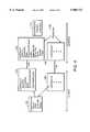
- FIG. 4Relevant data structures at both the router (which will be referred to as the client) and switch 12 (which will be referred to as the server) are shown in FIG. 4.
- ServerRecords 100one for each switch that is connected to the router, and for each ServerRecord a set of LinkRecords 102, one for each line between the router and the switch.
- ServerRecords 100are linked together in a ServerList.
- LinkRecords 102are stored in an array indexed by the link number. Neither the list or the array is explicitly shown in the figure.
- Each ServerRecord 100contains two variables that are set by management.
- the firstis a Name variable that is a local name assigned by management to this server.
- the second variableis Links, a variable that identifies the set of physical interfaces (i.e., lines) that connect the client to this particular server.
- FIG. 2there are two links between the client and the server shown in the figure; thus, the ServerRecord at the client points to the two corresponding link records. This information identifies the other members of the hunt group.
- LiveLinks variableis the subset of physical links that are operational. The traffic from the client to the server must only be split among the set of LiveLinks. As links fail and recover LiveLinks is updated by the protocol. Finally, there is a State variable which describes error conditions.
- Each LinkRecord 102contains variables required to implement a reliable transport connection with a corresponding link at the server end. Note that if there are multiple links between a client and a server, separate transport connections are set up on each link.
- a ServerId variableis a 48-bit unique Id of the remote server and the ConnectId is a 32 bit connection identifier.
- a State variableis the state of the connection; the link is considered to be operational when the connection state is ON.
- ClientLinks 106On the server side there is a variable called ClientLinks 106 that lists the set of server links that are connected to clients. For each such link, the server keeps a LinkRecord 108 corresponding to LinkRecord 102 kept at the client.
- the fields ServerId, ConnectId, and Statecorrespond to similar variables in the client LinkRecord 108. Also shown in the server link record are other variables that are not relevant to the invention described herein.
- Each ClientRecordstores a ClientId and a variable LiveLinks which represents the set of links to this client that are considered to be operational. If hunt groups are implemented on the server, the links in LiveLinks are configured into a hunt group.
Landscapes
- Engineering & Computer Science (AREA)
- Computer Networks & Wireless Communication (AREA)
- Signal Processing (AREA)
- Physics & Mathematics (AREA)
- Mathematical Physics (AREA)
- Data Exchanges In Wide-Area Networks (AREA)
Abstract
Description
Claims (4)
Priority Applications (1)
| Application Number | Priority Date | Filing Date | Title |
|---|---|---|---|
| US08/499,872US5905723A (en) | 1993-06-23 | 1995-07-10 | System for achieving scalable router performance |
Applications Claiming Priority (2)
| Application Number | Priority Date | Filing Date | Title |
|---|---|---|---|
| US8162393A | 1993-06-23 | 1993-06-23 | |
| US08/499,872US5905723A (en) | 1993-06-23 | 1995-07-10 | System for achieving scalable router performance |
Related Parent Applications (1)
| Application Number | Title | Priority Date | Filing Date |
|---|---|---|---|
| US8162393AContinuation | 1993-06-23 | 1993-06-23 |
Publications (1)
| Publication Number | Publication Date |
|---|---|
| US5905723Atrue US5905723A (en) | 1999-05-18 |
Family
ID=22165313
Family Applications (1)
| Application Number | Title | Priority Date | Filing Date |
|---|---|---|---|
| US08/499,872Expired - LifetimeUS5905723A (en) | 1993-06-23 | 1995-07-10 | System for achieving scalable router performance |
Country Status (1)
| Country | Link |
|---|---|
| US (1) | US5905723A (en) |
Cited By (29)
| Publication number | Priority date | Publication date | Assignee | Title |
|---|---|---|---|---|
| US6160811A (en)* | 1997-09-12 | 2000-12-12 | Gte Internetworking Incorporated | Data packet router |
| US6192048B1 (en)* | 1997-10-02 | 2001-02-20 | Mcdata Corporation | Method and apparatus for implementing hunt group support for a crosspoint controller |
| US6209039B1 (en)* | 1998-10-16 | 2001-03-27 | Mci Worldcom, Inc. | Method and apparatus for providing an interface between a plurality of frame relay networks |
| US6370121B1 (en) | 1998-06-29 | 2002-04-09 | Cisco Technology, Inc. | Method and system for shortcut trunking of LAN bridges |
| US6370145B1 (en)* | 1997-08-22 | 2002-04-09 | Avici Systems | Internet switch router |
| US20020051458A1 (en)* | 1998-04-24 | 2002-05-02 | Avici Systems | Composite trunking |
| US6393026B1 (en)* | 1998-09-17 | 2002-05-21 | Nortel Networks Limited | Data packet processing system and method for a router |
| WO2002045359A1 (en)* | 2000-11-29 | 2002-06-06 | Telefonaktiebolaget Lm Eriksson Publ | Method and apparatus for forwarding of telecommunications traffic |
| US6463067B1 (en)* | 1999-12-13 | 2002-10-08 | Ascend Communications, Inc. | Submission and response architecture for route lookup and packet classification requests |
| US6526021B1 (en)* | 1998-04-03 | 2003-02-25 | Alcatel Network Systems, Inc. | Clear channel 1:N SONET transport system and method |
| US20030058850A1 (en)* | 2001-07-05 | 2003-03-27 | Anand Rangarajan | Routing packets across multiple forwarding elements |
| US20030088826A1 (en)* | 2001-11-06 | 2003-05-08 | Govind Kizhepat | Method and apparatus for performing computations and operations on data using data steering |
| EP1168725A3 (en)* | 2000-06-19 | 2003-07-09 | Broadcom Corporation | Switch fabric with path redundancy |
| US20030142668A1 (en)* | 2002-01-31 | 2003-07-31 | Mosaid Technologies, Inc. | Trunking in a matrix |
| US20030233472A1 (en)* | 2002-06-14 | 2003-12-18 | Diwakar Tundlam | Dynamic load balancing within a network |
| US20040165601A1 (en)* | 2003-02-24 | 2004-08-26 | Hsin-Yuo Liu | Method and system for label-based packet forwarding among multiple forwarding elements |
| US6853638B2 (en)* | 1998-04-01 | 2005-02-08 | Cisco Technology, Inc. | Route/service processor scalability via flow-based distribution of traffic |
| US6889181B2 (en) | 1996-05-28 | 2005-05-03 | Cisco Technology, Inc. | Network flow switching and flow data export |
| US6947963B1 (en)* | 2000-06-28 | 2005-09-20 | Pluris, Inc | Methods and apparatus for synchronizing and propagating distributed routing databases |
| US6963572B1 (en) | 1999-10-22 | 2005-11-08 | Alcatel Canada Inc. | Method and apparatus for segmentation and reassembly of data packets in a communication switch |
| US6990103B1 (en)* | 1999-07-13 | 2006-01-24 | Alcatel Canada Inc. | Method and apparatus for providing distributed communication routing |
| US6996785B1 (en) | 2003-04-25 | 2006-02-07 | Universal Network Machines, Inc . | On-chip packet-based interconnections using repeaters/routers |
| US7068661B1 (en) | 1999-07-13 | 2006-06-27 | Alcatel Canada Inc. | Method and apparatus for providing control information in a system using distributed communication routing |
| US20070140240A1 (en)* | 1997-08-22 | 2007-06-21 | Dally William J | Internet switch router |
| US20070140247A1 (en)* | 2005-12-20 | 2007-06-21 | Lucent Technologies Inc. | Inter-FE MPLS LSP mesh network for switching and resiliency in SoftRouter architecture |
| US20080101402A1 (en)* | 2004-02-04 | 2008-05-01 | Jung-You Feng | Network communication apparatus and related method thereof |
| US7570583B2 (en) | 1997-12-05 | 2009-08-04 | Cisco Technology, Inc. | Extending SONET/SDH automatic protection switching |
| US9036629B2 (en) | 2012-04-27 | 2015-05-19 | Hewlett-Packard Development Company, L.P. | Switch module |
| US12242872B2 (en)* | 2014-09-26 | 2025-03-04 | Comcast Cable Communications, Llc | Systems and methods for providing availability to resources |
Citations (13)
| Publication number | Priority date | Publication date | Assignee | Title |
|---|---|---|---|---|
| US4737953A (en)* | 1986-08-04 | 1988-04-12 | General Electric Company | Local area network bridge |
| US5020052A (en)* | 1986-12-19 | 1991-05-28 | Alcatel N.V. | Packet switching network |
| US5088091A (en)* | 1989-06-22 | 1992-02-11 | Digital Equipment Corporation | High-speed mesh connected local area network |
| US5136580A (en)* | 1990-05-16 | 1992-08-04 | Microcom Systems, Inc. | Apparatus and method for learning and filtering destination and source addresses in a local area network system |
| US5138615A (en)* | 1989-06-22 | 1992-08-11 | Digital Equipment Corporation | Reconfiguration system and method for high-speed mesh connected local area network |
| US5140585A (en)* | 1990-07-19 | 1992-08-18 | Kabushiki Kaisha Toshiba | Star local-area network system |
| US5172372A (en)* | 1990-06-05 | 1992-12-15 | Kabushiki Kaisha Toshiba | Method and apparatus for determining transmission line for message transmission and reception in network system |
| US5177736A (en)* | 1990-02-07 | 1993-01-05 | Hitachi Ltd. | Packet switch |
| US5179558A (en)* | 1989-06-22 | 1993-01-12 | Digital Equipment Corporation | Routing apparatus and method for high-speed mesh connected local area network |
| US5239537A (en)* | 1990-10-17 | 1993-08-24 | Nec Corporation | Packet-switched network having alternate virtual paths |
| US5265257A (en)* | 1990-06-22 | 1993-11-23 | Digital Equipment Corporation | Fast arbiter having easy scaling for large numbers of requesters, large numbers of resource types with multiple instances of each type, and selectable queuing disciplines |
| US5490252A (en)* | 1992-09-30 | 1996-02-06 | Bay Networks Group, Inc. | System having central processor for transmitting generic packets to another processor to be altered and transmitting altered packets back to central processor for routing |
| US5509123A (en)* | 1994-03-22 | 1996-04-16 | Cabletron Systems, Inc. | Distributed autonomous object architectures for network layer routing |
- 1995
- 1995-07-10USUS08/499,872patent/US5905723A/ennot_activeExpired - Lifetime
Patent Citations (13)
| Publication number | Priority date | Publication date | Assignee | Title |
|---|---|---|---|---|
| US4737953A (en)* | 1986-08-04 | 1988-04-12 | General Electric Company | Local area network bridge |
| US5020052A (en)* | 1986-12-19 | 1991-05-28 | Alcatel N.V. | Packet switching network |
| US5088091A (en)* | 1989-06-22 | 1992-02-11 | Digital Equipment Corporation | High-speed mesh connected local area network |
| US5138615A (en)* | 1989-06-22 | 1992-08-11 | Digital Equipment Corporation | Reconfiguration system and method for high-speed mesh connected local area network |
| US5179558A (en)* | 1989-06-22 | 1993-01-12 | Digital Equipment Corporation | Routing apparatus and method for high-speed mesh connected local area network |
| US5177736A (en)* | 1990-02-07 | 1993-01-05 | Hitachi Ltd. | Packet switch |
| US5136580A (en)* | 1990-05-16 | 1992-08-04 | Microcom Systems, Inc. | Apparatus and method for learning and filtering destination and source addresses in a local area network system |
| US5172372A (en)* | 1990-06-05 | 1992-12-15 | Kabushiki Kaisha Toshiba | Method and apparatus for determining transmission line for message transmission and reception in network system |
| US5265257A (en)* | 1990-06-22 | 1993-11-23 | Digital Equipment Corporation | Fast arbiter having easy scaling for large numbers of requesters, large numbers of resource types with multiple instances of each type, and selectable queuing disciplines |
| US5140585A (en)* | 1990-07-19 | 1992-08-18 | Kabushiki Kaisha Toshiba | Star local-area network system |
| US5239537A (en)* | 1990-10-17 | 1993-08-24 | Nec Corporation | Packet-switched network having alternate virtual paths |
| US5490252A (en)* | 1992-09-30 | 1996-02-06 | Bay Networks Group, Inc. | System having central processor for transmitting generic packets to another processor to be altered and transmitting altered packets back to central processor for routing |
| US5509123A (en)* | 1994-03-22 | 1996-04-16 | Cabletron Systems, Inc. | Distributed autonomous object architectures for network layer routing |
Non-Patent Citations (12)
| Title |
|---|
| "Connection for Multi-Networking--Hardware or Software?," Network Monitor, Predicasts, 1991. |
| "Integrated Routing (and Bridging . . . )," William M. Seifert, Vice President, Chief Technical Officer, Wellfleet Communications, Inc., Bedford, Massachusetts 01730. |
| "The Intersect Local Bridge from Persoft," LAN Times, McGraw-Hill, Inc., 1991. |
| Communication Networks for Computers , Donald W. Davies and Derek L.A. Barber, John Wiley & Sons, London, 1973.* |
| Communication Networks for Computers, Donald W. Davies and Derek L.A. Barber, John Wiley & Sons, London, 1973. |
| Connection for Multi Networking Hardware or Software , Network Monitor, Predicasts, 1991.* |
| Data and Computer Communications , 2nd Edition, Macmillan Publishing , New York, 1988.* |
| Data and Computer Communications, 2nd Edition, Macmillan Publishing , New York, 1988. |
| Integrated Routing (and Bridging . . . ), William M. Seifert, Vice President, Chief Technical Officer, Wellfleet Communications, Inc., Bedford, Massachusetts 01730.* |
| The Intersect Local Bridge from Persoft, LAN Times, McGraw Hill, Inc., 1991.* |
| Webster s New World Dictonary of Computer Terms , 4th Edition, Compiled by Donald Spencer, Prentice Hall, New York, 1992.* |
| Webster's New World Dictonary of Computer Terms, 4th Edition, Compiled by Donald Spencer, Prentice Hall, New York, 1992. |
Cited By (52)
| Publication number | Priority date | Publication date | Assignee | Title |
|---|---|---|---|---|
| US6889181B2 (en) | 1996-05-28 | 2005-05-03 | Cisco Technology, Inc. | Network flow switching and flow data export |
| US7260518B2 (en) | 1996-05-28 | 2007-08-21 | Cisco Technology, Inc. | Network flow switching and flow data report |
| US20030118048A1 (en)* | 1997-08-22 | 2003-06-26 | Avici Systems | Internet switch router |
| US7187679B2 (en) | 1997-08-22 | 2007-03-06 | Avici Systems, Inc. | Internet switch router |
| US6370145B1 (en)* | 1997-08-22 | 2002-04-09 | Avici Systems | Internet switch router |
| US20070140240A1 (en)* | 1997-08-22 | 2007-06-21 | Dally William J | Internet switch router |
| US8325715B2 (en) | 1997-08-22 | 2012-12-04 | Futurewei Technologies, Inc. | Internet switch router |
| US6160811A (en)* | 1997-09-12 | 2000-12-12 | Gte Internetworking Incorporated | Data packet router |
| US6192048B1 (en)* | 1997-10-02 | 2001-02-20 | Mcdata Corporation | Method and apparatus for implementing hunt group support for a crosspoint controller |
| US7570583B2 (en) | 1997-12-05 | 2009-08-04 | Cisco Technology, Inc. | Extending SONET/SDH automatic protection switching |
| US6853638B2 (en)* | 1998-04-01 | 2005-02-08 | Cisco Technology, Inc. | Route/service processor scalability via flow-based distribution of traffic |
| US6526021B1 (en)* | 1998-04-03 | 2003-02-25 | Alcatel Network Systems, Inc. | Clear channel 1:N SONET transport system and method |
| US20020051458A1 (en)* | 1998-04-24 | 2002-05-02 | Avici Systems | Composite trunking |
| US7920555B2 (en) | 1998-04-24 | 2011-04-05 | Futurewei Technologies, Inc. | Composite trunking |
| US6370121B1 (en) | 1998-06-29 | 2002-04-09 | Cisco Technology, Inc. | Method and system for shortcut trunking of LAN bridges |
| US6393026B1 (en)* | 1998-09-17 | 2002-05-21 | Nortel Networks Limited | Data packet processing system and method for a router |
| US6209039B1 (en)* | 1998-10-16 | 2001-03-27 | Mci Worldcom, Inc. | Method and apparatus for providing an interface between a plurality of frame relay networks |
| US20060268877A1 (en)* | 1999-07-13 | 2006-11-30 | Gollamudi Ramana V | Method and apparatus for providing distributed communication routing |
| US7920563B2 (en) | 1999-07-13 | 2011-04-05 | Alcatel Lucent | Method and apparatus for providing distributed communication routing |
| US7068661B1 (en) | 1999-07-13 | 2006-06-27 | Alcatel Canada Inc. | Method and apparatus for providing control information in a system using distributed communication routing |
| US6990103B1 (en)* | 1999-07-13 | 2006-01-24 | Alcatel Canada Inc. | Method and apparatus for providing distributed communication routing |
| US7463650B2 (en) | 1999-10-22 | 2008-12-09 | Alcatel Lucent Canada Inc. | Method and apparatus for segmentation and reassembly of data packets in a communication switch |
| US20060050738A1 (en)* | 1999-10-22 | 2006-03-09 | David Carr | Method and apparatus for segmentation and reassembly of data packets in a communication switch |
| US6963572B1 (en) | 1999-10-22 | 2005-11-08 | Alcatel Canada Inc. | Method and apparatus for segmentation and reassembly of data packets in a communication switch |
| US6463067B1 (en)* | 1999-12-13 | 2002-10-08 | Ascend Communications, Inc. | Submission and response architecture for route lookup and packet classification requests |
| EP1168725A3 (en)* | 2000-06-19 | 2003-07-09 | Broadcom Corporation | Switch fabric with path redundancy |
| US6947963B1 (en)* | 2000-06-28 | 2005-09-20 | Pluris, Inc | Methods and apparatus for synchronizing and propagating distributed routing databases |
| WO2002045359A1 (en)* | 2000-11-29 | 2002-06-06 | Telefonaktiebolaget Lm Eriksson Publ | Method and apparatus for forwarding of telecommunications traffic |
| US20040062251A1 (en)* | 2000-11-29 | 2004-04-01 | Johan Johansson | Method and apparatus for forwarding of telecommunications traffic |
| US20040057429A1 (en)* | 2000-11-29 | 2004-03-25 | Lars Marklund | Method and telecommunications node for distribution of terminating traffic within telecommunications node |
| WO2002045366A1 (en)* | 2000-11-29 | 2002-06-06 | Telefonaktiebolaget L M Ericsson (Publ) | Method and telecommunications node for distribution of terminating traffic within telecommunications node |
| US7430213B2 (en) | 2000-11-29 | 2008-09-30 | Telefonaktiebolaget Lm Ericsson (Publ) | Method and telecommunications node for distribution of terminating traffic within telecommunications node |
| US7369562B2 (en)* | 2000-11-29 | 2008-05-06 | Telefonaktiebolaget Lm Ericsson (Publ) | Method and apparatus for forwarding of telecommunications traffic |
| US7126944B2 (en)* | 2001-07-05 | 2006-10-24 | Intel Corporation | Routing packets across multiple forwarding elements |
| US20030058850A1 (en)* | 2001-07-05 | 2003-03-27 | Anand Rangarajan | Routing packets across multiple forwarding elements |
| US7376811B2 (en)* | 2001-11-06 | 2008-05-20 | Netxen, Inc. | Method and apparatus for performing computations and operations on data using data steering |
| US20030088826A1 (en)* | 2001-11-06 | 2003-05-08 | Govind Kizhepat | Method and apparatus for performing computations and operations on data using data steering |
| US20080123528A1 (en)* | 2002-01-31 | 2008-05-29 | Wyatt Richard M | Trunking in a matrix |
| US8165117B2 (en) | 2002-01-31 | 2012-04-24 | Mosaid Technologies Incorporated | Trunking in a matrix |
| US8718056B2 (en) | 2002-01-31 | 2014-05-06 | Mosaid Technologies Incorporated | Trunking in a matrix |
| US7313135B2 (en) | 2002-01-31 | 2007-12-25 | Mosaid Technologies, Inc. | Trunking in a matrix |
| US20030142668A1 (en)* | 2002-01-31 | 2003-07-31 | Mosaid Technologies, Inc. | Trunking in a matrix |
| US20030233472A1 (en)* | 2002-06-14 | 2003-12-18 | Diwakar Tundlam | Dynamic load balancing within a network |
| US7930423B2 (en)* | 2002-06-14 | 2011-04-19 | Alcatel-Lucent Usa Inc. | Dynamic load balancing within a network |
| US20040165601A1 (en)* | 2003-02-24 | 2004-08-26 | Hsin-Yuo Liu | Method and system for label-based packet forwarding among multiple forwarding elements |
| US7397795B2 (en)* | 2003-02-24 | 2008-07-08 | Intel California | Method and system for label-based packet forwarding among multiple forwarding elements |
| US6996785B1 (en) | 2003-04-25 | 2006-02-07 | Universal Network Machines, Inc . | On-chip packet-based interconnections using repeaters/routers |
| US20080101402A1 (en)* | 2004-02-04 | 2008-05-01 | Jung-You Feng | Network communication apparatus and related method thereof |
| US7680113B2 (en)* | 2005-12-20 | 2010-03-16 | Alcatel-Lucent Usa Inc. | Inter-FE MPLS LSP mesh network for switching and resiliency in SoftRouter architecture |
| US20070140247A1 (en)* | 2005-12-20 | 2007-06-21 | Lucent Technologies Inc. | Inter-FE MPLS LSP mesh network for switching and resiliency in SoftRouter architecture |
| US9036629B2 (en) | 2012-04-27 | 2015-05-19 | Hewlett-Packard Development Company, L.P. | Switch module |
| US12242872B2 (en)* | 2014-09-26 | 2025-03-04 | Comcast Cable Communications, Llc | Systems and methods for providing availability to resources |
Similar Documents
| Publication | Publication Date | Title |
|---|---|---|
| US5905723A (en) | System for achieving scalable router performance | |
| CN1328885C (en) | Multibusiness network exchanger having cut-in quality | |
| EP1002397B1 (en) | A highly integrated multi-layer switch element architecture | |
| US6044080A (en) | Scalable parallel packet router | |
| US6775706B1 (en) | Multi-protocol switching system, line interface and multi-protocol processing device | |
| US5588121A (en) | Parallel computer having MAC-relay layer snooped transport header to determine if a message should be routed directly to transport layer depending on its destination | |
| CA2068056C (en) | Switching node in label multiplexing type switching network | |
| US6049528A (en) | Trunking ethernet-compatible networks | |
| US6160811A (en) | Data packet router | |
| Aweya | IP router architectures: an overview | |
| US6718393B1 (en) | System and method for dynamic distribution of data traffic load through multiple channels | |
| JP4076586B2 (en) | Systems and methods for multilayer network elements | |
| US5732080A (en) | Method and apparatus for controlling data flow within a switching device | |
| US5394402A (en) | Hub for segmented virtual local area network with shared media access | |
| US6804233B1 (en) | Method and system for link level server/switch trunking | |
| US6262976B1 (en) | System and method for network flow optimization using traffic classes | |
| EP1019833B1 (en) | Mechanism for packet field replacement in a multi-layered switched network element | |
| US6147999A (en) | ATM switch capable of routing IP packet | |
| US7110363B1 (en) | Virtual-channel merging | |
| US20040213272A1 (en) | Layer 2 switching device | |
| US7474661B2 (en) | Apparatus and method for distributing forwarding table lookup operations among a plurality of microengines in a high-speed routing node | |
| EP1226501A1 (en) | Network switch and components and method of operation | |
| US5434855A (en) | Method and apparatus for selective interleaving in a cell-switched network | |
| CN100399763C (en) | Multi-service network switch with automatic protection switching and its protection switching method | |
| US6760336B1 (en) | Flow detection scheme to support QoS flows between source and destination nodes |
Legal Events
| Date | Code | Title | Description |
|---|---|---|---|
| AS | Assignment | Owner name:CABLETRON SYSTEMS, INC., NEW HAMPSHIRE Free format text:ASSIGNMENT OF ASSIGNORS INTEREST;ASSIGNOR:DIGITAL EQUIPMENT CORPORATION;REEL/FRAME:009301/0017 Effective date:19980625 | |
| STCF | Information on status: patent grant | Free format text:PATENTED CASE | |
| FEPP | Fee payment procedure | Free format text:PAYOR NUMBER ASSIGNED (ORIGINAL EVENT CODE: ASPN); ENTITY STATUS OF PATENT OWNER: LARGE ENTITY | |
| AS | Assignment | Owner name:ENTERASYS NETWORKS, INC., NEW HAMPSHIRE Free format text:ASSIGNMENT OF ASSIGNORS INTEREST;ASSIGNOR:CABLETRON SYSTEMS, INC.;REEL/FRAME:011219/0376 Effective date:20000929 | |
| FPAY | Fee payment | Year of fee payment:4 | |
| AS | Assignment | Owner name:OBSIDIAN, LLC, CALIFORNIA Free format text:SECURITY AGREEMENT;ASSIGNOR:ENTERASYS NETWORKS, INC.;REEL/FRAME:017656/0552 Effective date:20060516 Owner name:WELLS FARGO FOOTHILL, INC., CALIFORNIA Free format text:SECURITY AGREEMENT;ASSIGNOR:ENTERASYS NETWORKS, INC.;REEL/FRAME:017656/0552 Effective date:20060516 | |
| FPAY | Fee payment | Year of fee payment:8 | |
| AS | Assignment | Owner name:WELLS FARGO TRUST CORPORATION LIMITED, AS SECURITY Free format text:GRANT OF SECURITY INTEREST IN U.S. PATENTS;ASSIGNOR:ENTERASYS NETWORKS INC.;REEL/FRAME:025339/0875 Effective date:20101109 | |
| FPAY | Fee payment | Year of fee payment:12 | |
| AS | Assignment | Owner name:ENTERASYS NETWORKS, INC., MASSACHUSETTS Free format text:RELEASE AND REASSIGNMENT OF PATENTS AND PATENT APPLICATIONS AT REEL/FRAME NO. 17656/0552;ASSIGNORS:WELLS FARGO CAPITAL FINANCE, INC. (FORMERLY KNOWN AS WELLS FARGO FOOTHILL, INC.);ENTERPRISE COMMUNICATIONS FUNDING GMBH, AS SUCCESSOR IN INTEREST TO OBSIDIAN, LLC;REEL/FRAME:025406/0769 Effective date:20101110 | |
| AS | Assignment | Owner name:ENTERASYS NETWORKS INC., MASSACHUSETTS Free format text:TERMINATION AND RELEASE OF SECURITY INTEREST IN PATENTS AT REEL/FRAME NO. 25339/0875;ASSIGNOR:WELLS FARGO TRUST CORPORATION LIMITED;REEL/FRAME:031558/0677 Effective date:20131031 | |
| AS | Assignment | Owner name:SILICON VALLEY BANK, CALIFORNIA Free format text:SECURITY AGREEMENT;ASSIGNOR:ENTERASYS NETWORKS, INC.;REEL/FRAME:036189/0509 Effective date:20150724 | |
| AS | Assignment | Owner name:SILICON VALLEY BANK, CALIFORNIA Free format text:AMENDED AND RESTATED PATENT AND TRADEMARK SECURITY AGREEMENT;ASSIGNOR:EXTREME NETWORKS, INC.;REEL/FRAME:040521/0762 Effective date:20161028 | |
| AS | Assignment | Owner name:SILICON VALLEY BANK, CALIFORNIA Free format text:SECOND AMENDED AND RESTATED PATENT AND TRADEMARK SECURITY AGREEMENT;ASSIGNOR:EXTREME NETWORKS, INC.;REEL/FRAME:043200/0614 Effective date:20170714 | |
| AS | Assignment | Owner name:ENTERASYS NETWORKS, INC., CALIFORNIA Free format text:RELEASE BY SECURED PARTY;ASSIGNOR:SILICON VALLEY BANK;REEL/FRAME:046047/0223 Effective date:20180501 Owner name:EXTREME NETWORKS, INC., CALIFORNIA Free format text:RELEASE BY SECURED PARTY;ASSIGNOR:SILICON VALLEY BANK;REEL/FRAME:046051/0775 Effective date:20180501 |