US5905608A - Dynamically tuned outer arms for improved rotary actuator performance - Google Patents
Dynamically tuned outer arms for improved rotary actuator performanceDownload PDFInfo
- Publication number
- US5905608A US5905608AUS08/933,697US93369797AUS5905608AUS 5905608 AUS5905608 AUS 5905608AUS 93369797 AUS93369797 AUS 93369797AUS 5905608 AUS5905608 AUS 5905608A
- Authority
- US
- United States
- Prior art keywords
- outer arm
- lower outer
- arm
- upper outer
- thinner portion
- Prior art date
- Legal status (The legal status is an assumption and is not a legal conclusion. Google has not performed a legal analysis and makes no representation as to the accuracy of the status listed.)
- Expired - Lifetime
Links
Images


Classifications
- G—PHYSICS
- G11—INFORMATION STORAGE
- G11B—INFORMATION STORAGE BASED ON RELATIVE MOVEMENT BETWEEN RECORD CARRIER AND TRANSDUCER
- G11B5/00—Recording by magnetisation or demagnetisation of a record carrier; Reproducing by magnetic means; Record carriers therefor
- G11B5/48—Disposition or mounting of heads or head supports relative to record carriers ; arrangements of heads, e.g. for scanning the record carrier to increase the relative speed
- G11B5/54—Disposition or mounting of heads or head supports relative to record carriers ; arrangements of heads, e.g. for scanning the record carrier to increase the relative speed with provision for moving the head into or out of its operative position or across tracks
- G11B5/55—Track change, selection or acquisition by displacement of the head
- G11B5/5521—Track change, selection or acquisition by displacement of the head across disk tracks
- G—PHYSICS
- G11—INFORMATION STORAGE
- G11B—INFORMATION STORAGE BASED ON RELATIVE MOVEMENT BETWEEN RECORD CARRIER AND TRANSDUCER
- G11B5/00—Recording by magnetisation or demagnetisation of a record carrier; Reproducing by magnetic means; Record carriers therefor
- G11B5/48—Disposition or mounting of heads or head supports relative to record carriers ; arrangements of heads, e.g. for scanning the record carrier to increase the relative speed
- G11B5/4806—Disposition or mounting of heads or head supports relative to record carriers ; arrangements of heads, e.g. for scanning the record carrier to increase the relative speed specially adapted for disk drive assemblies, e.g. assembly prior to operation, hard or flexible disk drives
- G11B5/4813—Mounting or aligning of arm assemblies, e.g. actuator arm supported by bearings, multiple arm assemblies, arm stacks or multiple heads on single arm
- G—PHYSICS
- G11—INFORMATION STORAGE
- G11B—INFORMATION STORAGE BASED ON RELATIVE MOVEMENT BETWEEN RECORD CARRIER AND TRANSDUCER
- G11B5/00—Recording by magnetisation or demagnetisation of a record carrier; Reproducing by magnetic means; Record carriers therefor
- G11B5/48—Disposition or mounting of heads or head supports relative to record carriers ; arrangements of heads, e.g. for scanning the record carrier to increase the relative speed
- G11B5/54—Disposition or mounting of heads or head supports relative to record carriers ; arrangements of heads, e.g. for scanning the record carrier to increase the relative speed with provision for moving the head into or out of its operative position or across tracks
- G11B5/55—Track change, selection or acquisition by displacement of the head
- G11B5/5521—Track change, selection or acquisition by displacement of the head across disk tracks
- G11B5/5582—Track change, selection or acquisition by displacement of the head across disk tracks system adaptation for working during or after external perturbation, e.g. in the presence of a mechanical oscillation caused by a shock
Definitions
- This inventionrelates generally to computer hard disk drives and, more particularly, to improvements to the rotary actuator of hard disk drives for better dynamic performance.
- Moving magnetic storage devicesespecially magnetic disk drives, are the memory devices of choice. This is due to their expanded non-volatile memory storage capability combined with a relatively low cost.
- Magnetic disk drivesare information storage devices which utilize at least one rotatable magnetic media disk having concentric data tracks defined for storing data, a magnetic recording head or transducer for reading data from and/or writing data to the various data tracks, a slider for supporting the transducer in proximity to the data tracks typically in a flying mode above the storage media, a suspension assembly for resiliently supporting the slider and the transducer over the data tracks, and a positioning actuator coupled to the transducer/slider/suspension combination for moving the transducer across the media to the desired data track and maintaining the transducer over the data track center line during a read or a write operation.
- the transduceris attached to or is formed integrally with the slider which supports the transducer above the data surface of the storage disk by a cushion of air, referred to as an air-bearing, generated by the rotating disk.
- the transducermay operate in contact with the surface of the disk.
- the suspensionprovides desired slider loading and dimensional stability between the slider and an actuator positioner arm which couples the transducer/slider/suspension assembly to the actuator.
- the actuatorpositions the transducer over the correct track according to the data desired on a read operation or to the correct track for placement of the data during a write operation.
- the actuatoris controlled to position the transducer over the desired data track by shifting the combination assembly across the surface of the disk in a direction generally transverse to the data tracks.
- the actuatormay include a single positioner arm extending from a pivot point, or alternatively a plurality of positioner arms arranged in a comb-like fashion extending from a pivot point.
- a rotary voice coil motor (VCM)is attached to the rear portion of the actuator assembly to power movement of the actuator over the disks.
- the VCM located at the rear portion of the actuator assemblyis comprised of a top plate spaced above a bottom plate with a magnet or pair of magnets therebetween.
- the VCMfurther includes an electrically conductive coil disposed within the rearward extension of the actuator assembly and between the top and bottom plates, while overlying the magnet in a plane parallel to the magnet. In operation, current passes through the coil and interacts with the magnetic field of the magnet so as to rotate the actuator assembly around its pivot and thus positioning the transducer as desired.
- the magnetic media disk or disks in the disk driveare mounted to a spindle.
- the spindleis attached to a spindle motor which rotates the spindle and the disks to provide read/write access to the various portions on the concentric tracks on the disks.
- the actuatordriven by the VCM, is positioned radially over the disk surface under the control of a positioning servo system.
- the servo systemis designed to accurately position the read/write transducer over a selected data track on the disk in as short a time as possible.
- the actuators of most disk drive systemshave at least two positioner arms, an outer upper positioner arm (outer upper arm) and an outer lower positioner arm (outer lower arm) so that data may be written to and read from both surfaces of the disk.
- Disk drive systems having more than one diskhave actuators with one or two outer arms and at least one inner positioner arm (inner arm).
- the outer armseach support a single suspension and corresponding slider/transducer assembly.
- the inner armseach support two suspensions with their slider/transducer assemblies, the suspensions being mounted in a back-to-back configuration on each side of the positioner arm.
- Actuator positioner armshave resonant frequencies that can adversely affect the performance of the servo system.
- the dynamics of the upper outer arm and the lower outer armare typically different than the dynamics of the inner arms due to the fact that the outer arms generally support one suspension and the inner arms support two suspensions.
- the different dynamics of the outer and inner armsleads to additional modes of vibration on the actuator that can degrade performance of the disk drive system.
- an object of the present inventionto provide an improved actuator that has reduced modes of vibration of the positioner arms, thereby resulting in improved performance and stability.
- the present inventionis an actuator assembly for magnetic storage disk drive systems comprising an upper outer arm and a lower outer arm and at least one inner arm.
- the dynamics of the upper outer arm and the lower outer armare tuned to match the dynamics of the inner arm or arms resulting in a reduced number of vibration modes of the positioner arms on the actuator assembly.
- the dynamics of the outer armsare tuned to match the dynamics of the inner arms by changing the outer arm mass, stiffness or both in an appropriate manner so that the unwanted vibration modes are shifted in frequency.
- the actuator assembly of the present inventioncomprises an upper outer arm and a lower outer arm of reduced thickness compared to the inner arms.
- the upper outer arm and lower outer armhave notches at high strain energy points to reduce the stiffness of the outer actuator arms.
- the upper and lower outer armshave both reduced thickness as compared to the inner arms as well as notches at high strain energy points.
- the modifications of the outer armsare made with the object of moving unwanted vibration modes of said outer arms to coincide with an appropriate vibration mode of the inner arms.
- FIG. 1is a schematic illustration of a magnetic recording disk drive system
- FIG. 2is a perspective view of a disk drive
- FIG. 3is a perspective view of an actuator assembly
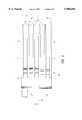
- FIG. 4is a side elevation view of an actuator assembly of an embodiment of the present invention.
- FIG. 5ais a plan view of an outer positioner arm
- FIG. 5bis a plan view of an inner positioner arm
- FIG. 6is a graph showing transfer functions calculated for an outer positioner arm.
- FIG. 7is a graph showing transfer functions calculated for an inner positioner arm.
- FIG. 1there is shown a schematic illustration of a disk drive 20 embodying the present invention.
- a disk drive 20embodying the present invention.
- at least one rotatable magnetic disk 22is supported on a spindle 26 and rotated by a disk drive motor 30.
- the magnetic recording media on each diskis in the form of an annular pattern of concentric data tracks (not shown) on disk 22.
- At least one slider 24is positioned on the disk 22, each slider 24 supporting one or more magnetic read/write heads 34. As the disks rotate, slider 24 is moved radially in and out over disk surface 36 so that heads 34 may access different portions of the disk where desired data is recorded.
- Each slider 24is attached to a positioner arm 32 by means of a suspension 28.
- the suspension 28provides a slight spring force which biases slider 24 against the disk surface 36.
- Each positioner arm 32is attached to an actuator means 42.
- the actuator means as shown in FIG. 2may be a voice coil motor (VCM).
- VCMcomprises a coil movable within a fixed magnetic field, the direction and speed of the coil movements being controlled by the motor current signals supplied by controller 46.
- the rotation of disk 22generates an air bearing between slider 24 and disk surface 36 which exerts an upward force or lift on the slider.
- the air bearingthus counter-balances the slight spring force of suspension 28 and supports slider 24 off and slightly above the disk surface 36 by a small, substantially constant spacing during normal operation.
- control unit 46The various components of the disk drive system 20 are controlled in operation by control signals generated by control unit 46, such as access control signals and internal clock signals.
- control unit 46comprises logic control circuits, storage means and a microprocessor.
- the control unit 46generates control signals to control various system operations such as drive motor control signals on line 38 and head position and seek control signals on line 44.
- the control signals on line 44provide the desired current profiles to optimally move and position slider 24 to the desired data track on disk 22.
- Read and write signalsare communicated to and from read/write heads 34 by means of recording channel 40.
- disk storage systemsmay contain a large number of disks and actuators, and each actuator may support a number of sliders.
- FIG. 2shows a hard disk drive designated by the general number 50.
- the lid 54 of the disk driveis shown exploded. In operation, the lid would be disposed on top of the housing 52.
- the disk drive 50comprises one or more magnetic disks 56.
- the disksmay be conventional particulate or thin film recording disks, which are capable of storing digital data in concentric tracks.
- both sides of the disks 56are available for storage, and it will be recognized by one of ordinary skill in the art that the disk drive 50 may include any number of such disks 56.
- the disks 56are mounted to a spindle 58.
- the spindle 58is attached to a spindle motor (not shown) which rotates the spindle 58 and the disks 56 to provide read/write access to the various portions of the concentric tracks on the disks 56.
- An actuator assembly 76includes a positioner arm 60, and a suspension assembly 62.
- the suspension assembly 62includes a slider/transducer assembly 64 at its distal end. Although only one slider/transducer assembly 64 of the suspension assembly 62 is shown, it will be recognized that the disk drive 50 has one slider/transducer assembly 64 for each side of each disk 56 included in the disk drive 50.
- the positioner arm 60further comprises a pivot 72 around which the actuator assembly 76 pivots.
- the disk drive 50further includes a read/write chip 80.
- the read/write chip 80cooperates with the slider transducer assembly 64 to read data from or write data to the disks 56.
- a flexible printed circuit member or actuator flex cable 78carries digital signals between the read/write chip 80 and a connector pin assembly (not shown) which interfaces with the external signal processing electronics.
- the main function of the actuator assembly 76is to move the positioner arm 60 around the pivot 72.
- Part of the actuator assembly 76is the voice coil motor (VCM) assembly 74 which comprises a VCM bottom plate, a magnet and a VCM top plate in combination with an actuator coil. Current passing through the actuator coil interacts with the magnetic field of the magnet to rotate the positioner arm 60 and suspension assembly 62 around the pivot 72, thus positioning the slider/transducer assembly 64 as desired.
- VCMvoice coil motor
- the actuator assembly 76comprises a plurality of positioner arms 60 fixed in a comb-like arrangement such that the inner arms 65 fit between the disks 56 forming disk stack 70 and the outer arms 66, 68 extend over the top surface of the top disk and the bottom surface of the bottom disk, respectively.
- the inner arms 65each support two suspension assemblies 62 (upper and lower suspension assemblies) with attached slider/transducer assemblies 64.
- the upper outer arm 66supports one suspension assembly 62 with its slider/transducer assembly 64 to access data on the top surface of the top disk of disk stack 70.
- the lower outer arm 68supports one suspension assembly 62 with its slider/transducer assembly 64 to access data on the bottom surface of the bottom disk of disk stack 70.
- FIG. 3is a perspective view of an actuator assembly 90.
- the actuator assembly 90comprises a body 102, a lower outer arm 92, an upper outer arm 94, one or more inner arms 96, and actuator coil 104 located between supporting arms 98, 100.
- the body 102is supported by bearings (not shown) which allow the actuator assembly 90 to rotate about a vertical axis 95 when the actuator assembly 90 is mounted in a disk file.
- the body 102supports positioner arms 92, 94, 96 which in turn support the suspension assemblies (not shown) on which slider/transducer assemblies (not shown) are fixed.
- the actuator coil support arms 98, 100support the actuator coil 104 which is part of the VCM assembly which works to position the actuator assembly radially with respect to the disk surfaces.
- the actuator assembly 90When installed in a disk drive system, the actuator assembly 90 with suspension assemblies fixed on the positioner arms 92, 94, 96 is rotated by the VCM motor to position the slider/transducer assemblies at the desired disk radius to read or write data on a data track on the recording media coating the disk surface.
- the forces applied to the actuator assembly 90 by the VCM motorcan excite mechanical resonances of the actuator assembly.
- Resonances of the actuator assembly 90 in the plane of the radial motion of the actuator assembly 90are of particular concern since they directly affect the settling time after a seek of the slider/transducer assemblies over the desired data track.
- settling timeit is meant the time for the transducer to become stably positioned over the track.
- the outer arms 92, 94each support one suspension assembly while the inner arms 96 each support two suspension assemblies, the outer arms have resonance modes at higher vibration frequencies.
- the higher frequency modesare a consequence of the lower mass supported by the outer arms 92, 94. Because these additional higher frequency modes degrade the performance of the disk file, it is desirable to alter the design of the outer arms in such a manner that the unwanted high frequency modes are lowered in frequency to coincide with the resonance modes of the inner arms 96. Lowering the frequencies of these outer arm modes can be accomplished by adding mass to the outer arms 92, 94, by removal of material at selected high stress positions on the outer arms 92, 94 or by reducing the thickness of selected portions of the outer arms 92, 94.
- Addition of mass to the outer arms 92, 94is not the most desirable embodiment since additional mass on the actuator assembly 90 reduces performance of the disk drive. Nevertheless, the addition of mass to the outer arms 92, 94 so that the outer arms 92, 94 are thicker than inner arms 96 is one alternative embodiment to the present invention.
- the preferred methods of tuning the outer arm resonances to match the inner arm resonancesare the removal of material at selected high stress points of the outer arm 94 and/or reducing the thickness of selected portions of the outer arms 92, 94 or some combination of the three approaches.
- Actuator assembly 110comprises a body 112, an upper outer arm 114, a lower outer arm 116, one or more inner arms 118, and VCM coil support arms 126.
- the body 112supports the positioner arms 114, 116, 118 on which suspension assemblies (not shown) are fixed on surfaces 124.
- Each inner arm 118supports two suspension assemblies which access data stored on the disk surfaces rotating above and below the inner arm 118.
- the upper outer arm 114supports one suspension assembly which accesses data stored on the upper surface of the top disk of the disk stack.
- the lower outer arm 116supports one suspension assembly which accesses data stored on the lower surface of the bottom disk of the disk stack.
- upper outer arm 114has a thinned portion 120 on its upper surface and lower outer arm 116 has a thinned portion 122 on its lower surface.
- the thinned sections 120, 122 of the outer arms 114, 116have reduced stiffness relative to the stiffness of the inner arms 118.
- FIGS. 5a and 5bplan views of sections of the outer arm 114 and the inner arm 118 illustrate further aspects of the best embodiment of the present invention.
- FIG. 5ais a plan view of section A--A of FIG. 4 of the upper outer arm 114.
- FIG. 5aalso represents a plan view of section C--C of FIG. 4 of the lower outer arm 116.
- FIG. 5ashows the plan view of the thinned portion 120 of the upper outer arm 114 for section A--A or the plan view of the thinned portion 122 for section C--C.
- FIG. 5bis a plan view of section B--B of inner arm 118 showing that the positioner arms of the present embodiment have a cross bar 128 to add stiffness to the structure.
- the cross bar 128 of the outer arms 114, 116has material removed to form notched portions 130 at regions of high stress during in plane vibration deformation.
- the notched portions 130have the effect of further decreasing the stiffness of the outer arms 114, 116 relative to the inner arms 118.
- the outer arms 114, 116may instead have material removed to form notched portions 131 (shown in shadow) which also may be regions of high stress during deformation of the present geometry. It is understood that variations in the geometry would lead to other high stress regions which may be notched and thus within the spirit and scope of the present invention.
- FIG. 6mechanical transfer functions obtained from a finite element calculation are shown for an outer arm 114, or 116 of FIG. 5a.
- the transfer functionsare graphs showing the in plane vibration displacement amplitude response as a function of frequency to an input torque applied to the actuator assembly at the coil in the plane of actuator rotation.
- the two curves shown in FIG. 6correspond to the transfer functions obtained for the outer arms 114, 116 before tuning 140 and after tuning 142, respectively, by the process of decreasing the stiffness by the methods of the present invention.
- the large peak near 3500 Hzcorresponds to a resonance due to a fundamental bending mode of the actuator assembly about the pivot point at the bearings.
- the large peak at 4800 Hzis the resonance introduced by reducing the mass of the outer arms relative to the mass of the inner arms by only supporting one suspension assembly on the outer arms. This resonance corresponds to a scissor-like mode of the outer arms relative to the inner arms.
- the small peak near 4200 Hzis a scissor-like mode of the inner arms.
- the large peak at 4800 Hzis the unwanted resonance that can be tuned by the methods of this invention to improve performance of the disk drive.
- the transfer function obtained for the outer arms 114, 116 after tuning 142shows the significant effects of reducing the outer arm stiffness on the amplitude and frequency of the 4800 Hz resonance.
- the frequency of the resonancehas been lowered to 4300 Hz so that it now coincides with the scissor-like mode of the inner arms.
- the amplitude of the resulting low frequency modeis significantly lower after tuning.
- the two curves shown in the Figurecorrespond to the in plane vibration displacement amplitude as a function of frequency for an inner positioner arm 118 obtained before tuning 144 and after tuning 146, respectively, of the stiffness of the outer arms 114, 116 by the methods of the present invention.
- the transfer function before tuning 144shows the peak at 3500 Hz corresponding to the bending mode of the actuator assembly about the pivot point and also shows peaks at 4800 Hz due to the scissor-like mode of the outer arms and at 4300 Hz due to the inner arm scissor-like mode.
- the transfer function after tuning 146shows that the resonance at 4200 Hz has been shifted in frequency to 4100 Hz and that the 4800 Hz scissor-like mode of the outer arms has been lowered in frequency to overlap the 4300 Hz mode of the inner arms.
- tuning of the outer arm resonanceswas accomplished by reducing the stiffness of said outer arms by two methods, by thinning portions of the outer arms and by removal of material at high stress points of the outer arms to form notches.
- the tuning of the outer arm resonancescan be accomplished by addition mass to the outer arms, or any combination of the three approaches. It will be appreciated by those skilled in the art, that the same tuning results can be accomplished by using one or the other of the stiffness reducing methods of the present embodiment or by using a different balance of the two methods. It will also be appreciated by those skilled in the art, that reducing the stiffness of the outer arms can be accomplished by thinning other portions of the outer arms and by removal of material at other stress points of the outer arms than those described in this embodiment.
Landscapes
- Moving Of Heads (AREA)
- Reciprocating, Oscillating Or Vibrating Motors (AREA)
Abstract
Description
Claims (44)
Priority Applications (3)
| Application Number | Priority Date | Filing Date | Title |
|---|---|---|---|
| US08/933,697US5905608A (en) | 1997-09-19 | 1997-09-19 | Dynamically tuned outer arms for improved rotary actuator performance |
| KR1019980032326AKR100323259B1 (en) | 1997-09-19 | 1998-08-08 | Dynamically tuned outer arms for improved rotary actuator performance |
| MYPI98003735AMY114957A (en) | 1997-09-19 | 1998-08-17 | Dynamically tuned outer arms for improved rotary actuator performance. |
Applications Claiming Priority (1)
| Application Number | Priority Date | Filing Date | Title |
|---|---|---|---|
| US08/933,697US5905608A (en) | 1997-09-19 | 1997-09-19 | Dynamically tuned outer arms for improved rotary actuator performance |
Publications (1)
| Publication Number | Publication Date |
|---|---|
| US5905608Atrue US5905608A (en) | 1999-05-18 |
Family
ID=25464369
Family Applications (1)
| Application Number | Title | Priority Date | Filing Date |
|---|---|---|---|
| US08/933,697Expired - LifetimeUS5905608A (en) | 1997-09-19 | 1997-09-19 | Dynamically tuned outer arms for improved rotary actuator performance |
Country Status (3)
| Country | Link |
|---|---|
| US (1) | US5905608A (en) |
| KR (1) | KR100323259B1 (en) |
| MY (1) | MY114957A (en) |
Cited By (20)
| Publication number | Priority date | Publication date | Assignee | Title |
|---|---|---|---|---|
| US5991122A (en)* | 1996-09-24 | 1999-11-23 | Hutchinson Technology Incorporated | Method for designing a suspension having weakening structures for resonance-optimized side profile |
| US6088194A (en)* | 1998-06-12 | 2000-07-11 | International Business Machines Corporation | Dual mode actuator |
| GB2358730A (en)* | 1999-11-17 | 2001-08-01 | Samsung Electronics Co Ltd | Actuator arm of varying thickness |
| US6422080B1 (en)* | 2000-02-07 | 2002-07-23 | Seagate Technology Llc | Resonance control method for a disc drive actuator assembly having discrete bearings |
| US6532135B1 (en)* | 2000-06-06 | 2003-03-11 | Maxtor Corporation | Suspension load beam for disk drive actuator |
| US6538853B1 (en)* | 1999-09-13 | 2003-03-25 | Maxtor Corporation | E-block having improved resonance characteristics and improved fragility |
| US20030081356A1 (en)* | 2001-10-30 | 2003-05-01 | Toshihiko Shimizu | Carriage arm assembly for locating magnetic head, and magnetic disk apparatus using the same |
| US6560852B2 (en) | 2000-02-07 | 2003-05-13 | Seagate Technology Llc | Disc drive with actuator arm configured for reduced out-of-phase motion |
| US20030206366A1 (en)* | 2002-05-06 | 2003-11-06 | Dan Blick | Reaction mass dual-stage actuator (DSA) and sensor |
| US20040095672A1 (en)* | 2002-11-18 | 2004-05-20 | Price Kirk B. | Apparatus and method for reducing vibrational excitation in storage devices with dual stage actuators |
| US20060002029A1 (en)* | 2004-06-30 | 2006-01-05 | Hitachi Global Storage Technologies Netherlands B.V. | System, method, and apparatus for reducing off-track gain for a disk drive actuator |
| US7016157B1 (en) | 1999-09-13 | 2006-03-21 | Maxtor Corporation | E-block having improved resonance characteristics and improved fragility |
| US7355819B2 (en)* | 2000-03-31 | 2008-04-08 | Seagate Technology Llc | Machining actuator periphery to reduce resonance variation |
| US7564651B2 (en) | 2005-04-14 | 2009-07-21 | Hitachi Global Storage Technologies Netherlands B.V. | Integrated-lead suspension vibration-canceling member |
| US7576955B1 (en) | 2005-12-06 | 2009-08-18 | Western Digital Technologies, Inc. | Disk drive actuator with outer arms having regions of reduced width and increased thickness |
| US7636222B1 (en) | 2006-02-10 | 2009-12-22 | Maxtor Corporation | Tuned mass actuator arms for decreasing track misregistration in a depopulated head suspension disk drive |
| US8553367B1 (en)* | 2008-08-12 | 2013-10-08 | Western Digital Technologies, Inc. | Depopulated head stack assembly having a necked dummy mass |
| US8830634B2 (en) | 2012-05-31 | 2014-09-09 | HGST Netherlands B.V. | Asymmetric comb bore in actuator design |
| CN114267379A (en)* | 2020-09-16 | 2022-04-01 | 株式会社东芝 | disk device |
| US20240144967A1 (en)* | 2022-11-01 | 2024-05-02 | Western Digital Technologies, Inc. | Hard disk drive carriage arm depression |
Families Citing this family (1)
| Publication number | Priority date | Publication date | Assignee | Title |
|---|---|---|---|---|
| JP2001135043A (en)* | 1999-11-02 | 2001-05-18 | Nagase & Co Ltd | Rocking actuator |
Citations (19)
| Publication number | Priority date | Publication date | Assignee | Title |
|---|---|---|---|---|
| JPS60106002A (en)* | 1983-11-14 | 1985-06-11 | Matsushita Electric Ind Co Ltd | Pick-up arm device |
| JPH01113966A (en)* | 1987-10-28 | 1989-05-02 | Hitachi Ltd | magnetic disk device |
| US4933791A (en)* | 1988-07-18 | 1990-06-12 | Seagate Technology, Inc. | Head arm flexure for disc drives |
| US4942491A (en)* | 1987-09-07 | 1990-07-17 | Teac Corporation | Magnetic head supporting device |
| US4943875A (en)* | 1988-10-13 | 1990-07-24 | International Business Machines Corporation | Magnetic disk file head suspension assembly mounting means |
| JPH02306477A (en)* | 1989-05-20 | 1990-12-19 | Tokico Ltd | magnetic disk device |
| US5014142A (en)* | 1988-03-24 | 1991-05-07 | Hitachi, Ltd. | Magnetic disk apparatus with head supporting structures of different proper oscillations |
| US5014145A (en)* | 1987-07-10 | 1991-05-07 | Hitachi, Ltd. | Head arm structure mounting a circuit element in a magnetic disc device |
| US5068959A (en)* | 1988-07-11 | 1991-12-03 | Digital Equipment Corporation | Method of manufacturing a thin film head |
| JPH0492270A (en)* | 1990-08-07 | 1992-03-25 | Tokico Ltd | magnetic disk device |
| JPH04134764A (en)* | 1990-09-26 | 1992-05-08 | Mitsubishi Electric Corp | head positioning device |
| JPH04216376A (en)* | 1990-12-17 | 1992-08-06 | Mitsubishi Electric Corp | Head positioning mechanism for fixed magnetic disk drives |
| US5161077A (en)* | 1990-11-09 | 1992-11-03 | Seagate Technology, Inc. | Actuator arm with a steel sleeve for thermal off track compensation |
| US5268805A (en)* | 1991-08-16 | 1993-12-07 | Micropolis Corporation | Low inertia Winchester disk drive actuator |
| JPH06251518A (en)* | 1992-12-29 | 1994-09-09 | Sony Corp | Actuator |
| US5438747A (en)* | 1994-03-09 | 1995-08-08 | International Business Machines Corporation | Method of making a thin film merged MR head with aligned pole tips |
| US5452164A (en)* | 1994-02-08 | 1995-09-19 | International Business Machines Corporation | Thin film magnetic write head |
| US5459921A (en)* | 1993-11-12 | 1995-10-24 | Seagate Technology, Inc. | Method of making a disc drive actuator arm with arm compliance compensation |
| JPH08287625A (en)* | 1995-04-11 | 1996-11-01 | Fujitsu Ltd | Actuator, FPC, bush tap, and disk device using these |
- 1997
- 1997-09-19USUS08/933,697patent/US5905608A/ennot_activeExpired - Lifetime
- 1998
- 1998-08-08KRKR1019980032326Apatent/KR100323259B1/ennot_activeExpired - Fee Related
- 1998-08-17MYMYPI98003735Apatent/MY114957A/enunknown
Patent Citations (19)
| Publication number | Priority date | Publication date | Assignee | Title |
|---|---|---|---|---|
| JPS60106002A (en)* | 1983-11-14 | 1985-06-11 | Matsushita Electric Ind Co Ltd | Pick-up arm device |
| US5014145A (en)* | 1987-07-10 | 1991-05-07 | Hitachi, Ltd. | Head arm structure mounting a circuit element in a magnetic disc device |
| US4942491A (en)* | 1987-09-07 | 1990-07-17 | Teac Corporation | Magnetic head supporting device |
| JPH01113966A (en)* | 1987-10-28 | 1989-05-02 | Hitachi Ltd | magnetic disk device |
| US5014142A (en)* | 1988-03-24 | 1991-05-07 | Hitachi, Ltd. | Magnetic disk apparatus with head supporting structures of different proper oscillations |
| US5068959A (en)* | 1988-07-11 | 1991-12-03 | Digital Equipment Corporation | Method of manufacturing a thin film head |
| US4933791A (en)* | 1988-07-18 | 1990-06-12 | Seagate Technology, Inc. | Head arm flexure for disc drives |
| US4943875A (en)* | 1988-10-13 | 1990-07-24 | International Business Machines Corporation | Magnetic disk file head suspension assembly mounting means |
| JPH02306477A (en)* | 1989-05-20 | 1990-12-19 | Tokico Ltd | magnetic disk device |
| JPH0492270A (en)* | 1990-08-07 | 1992-03-25 | Tokico Ltd | magnetic disk device |
| JPH04134764A (en)* | 1990-09-26 | 1992-05-08 | Mitsubishi Electric Corp | head positioning device |
| US5161077A (en)* | 1990-11-09 | 1992-11-03 | Seagate Technology, Inc. | Actuator arm with a steel sleeve for thermal off track compensation |
| JPH04216376A (en)* | 1990-12-17 | 1992-08-06 | Mitsubishi Electric Corp | Head positioning mechanism for fixed magnetic disk drives |
| US5268805A (en)* | 1991-08-16 | 1993-12-07 | Micropolis Corporation | Low inertia Winchester disk drive actuator |
| JPH06251518A (en)* | 1992-12-29 | 1994-09-09 | Sony Corp | Actuator |
| US5459921A (en)* | 1993-11-12 | 1995-10-24 | Seagate Technology, Inc. | Method of making a disc drive actuator arm with arm compliance compensation |
| US5452164A (en)* | 1994-02-08 | 1995-09-19 | International Business Machines Corporation | Thin film magnetic write head |
| US5438747A (en)* | 1994-03-09 | 1995-08-08 | International Business Machines Corporation | Method of making a thin film merged MR head with aligned pole tips |
| JPH08287625A (en)* | 1995-04-11 | 1996-11-01 | Fujitsu Ltd | Actuator, FPC, bush tap, and disk device using these |
Cited By (41)
| Publication number | Priority date | Publication date | Assignee | Title |
|---|---|---|---|---|
| US5991122A (en)* | 1996-09-24 | 1999-11-23 | Hutchinson Technology Incorporated | Method for designing a suspension having weakening structures for resonance-optimized side profile |
| US6088194A (en)* | 1998-06-12 | 2000-07-11 | International Business Machines Corporation | Dual mode actuator |
| US6538853B1 (en)* | 1999-09-13 | 2003-03-25 | Maxtor Corporation | E-block having improved resonance characteristics and improved fragility |
| US7016157B1 (en) | 1999-09-13 | 2006-03-21 | Maxtor Corporation | E-block having improved resonance characteristics and improved fragility |
| US6775106B1 (en) | 1999-09-13 | 2004-08-10 | Maxtor Corporation | E-block having improved resonance characteristics and improved fragility |
| GB2358730B (en)* | 1999-11-17 | 2002-04-24 | Samsung Electronics Co Ltd | Stepped actuator arm of a hard disk drive for high shock performance |
| GB2358730A (en)* | 1999-11-17 | 2001-08-01 | Samsung Electronics Co Ltd | Actuator arm of varying thickness |
| US6422080B1 (en)* | 2000-02-07 | 2002-07-23 | Seagate Technology Llc | Resonance control method for a disc drive actuator assembly having discrete bearings |
| US6560852B2 (en) | 2000-02-07 | 2003-05-13 | Seagate Technology Llc | Disc drive with actuator arm configured for reduced out-of-phase motion |
| US7355819B2 (en)* | 2000-03-31 | 2008-04-08 | Seagate Technology Llc | Machining actuator periphery to reduce resonance variation |
| US6532135B1 (en)* | 2000-06-06 | 2003-03-11 | Maxtor Corporation | Suspension load beam for disk drive actuator |
| US6938326B1 (en) | 2000-06-06 | 2005-09-06 | Maxtor Corporation | Method of making at least one suspension load beam for an actuator assembly of a disk drive |
| US6687091B1 (en) | 2000-06-06 | 2004-02-03 | Maxtor Corporation | Suspension load beam for disk drive actuator with notch for reducing spring rate |
| US7031118B2 (en)* | 2001-10-30 | 2006-04-18 | Hitachi Global Storage Technologies Japan, Ltd. | Carriage arm assembly for locating magnetic head, and magnetic disk apparatus using the same |
| US20030081356A1 (en)* | 2001-10-30 | 2003-05-01 | Toshihiko Shimizu | Carriage arm assembly for locating magnetic head, and magnetic disk apparatus using the same |
| US20050180056A1 (en)* | 2001-10-30 | 2005-08-18 | Toshihiko Shimizu | Carriage arm assembly for locating magnetic head, and magnetic disk apparatus using the same |
| US6879467B2 (en)* | 2001-10-30 | 2005-04-12 | Hitachi Global Storage Technologies Japan, Ltd. | Carriage arm assembly for locating magnetic head, and magnetic disk apparatus using the same |
| US7545607B2 (en) | 2001-10-30 | 2009-06-09 | Hitachi Global Storage Technologies Japan, Ltd. | Carriage arm assembly for locating magnetic head, and magnetic disk apparatus using the same |
| US20060158786A1 (en)* | 2001-10-30 | 2006-07-20 | Toshihiko Shimizu | Carriage arm assembly for locating magnetic head, and magnetic disk apparatus using the same |
| US7110223B2 (en) | 2001-10-30 | 2006-09-19 | Hitachi Global Storage Technologies Japan, Ltd. | Carriage arm assembly for locating magnetic head, and magnetic disk apparatus using the same |
| US20070002497A1 (en)* | 2001-10-30 | 2007-01-04 | Toshihiko Shimizu | Carriage arm assembly for locating magnetic head, and magnetic disk apparatus using the same |
| US6922303B2 (en) | 2002-05-06 | 2005-07-26 | Samsung Electronics Co., Ltd. | Reaction mass dual-stage actuator (DSA) and sensor |
| US20030206366A1 (en)* | 2002-05-06 | 2003-11-06 | Dan Blick | Reaction mass dual-stage actuator (DSA) and sensor |
| US20040095672A1 (en)* | 2002-11-18 | 2004-05-20 | Price Kirk B. | Apparatus and method for reducing vibrational excitation in storage devices with dual stage actuators |
| US6922305B2 (en) | 2002-11-18 | 2005-07-26 | Hitachi Global Storage Technologies Netherlands B.V. | Apparatus and method for reducing vibrational excitation in storage devices with dual stage actuators |
| US20080106822A1 (en)* | 2004-06-30 | 2008-05-08 | Brad Vaughn Johnson | Method for reducing off-track gain for a disk drive actuator |
| US7239486B2 (en)* | 2004-06-30 | 2007-07-03 | Hitachi Global Storage Technologies Netherlands B.V. | System and apparatus for reducing off-track gain for a disk drive actuator |
| US20060002029A1 (en)* | 2004-06-30 | 2006-01-05 | Hitachi Global Storage Technologies Netherlands B.V. | System, method, and apparatus for reducing off-track gain for a disk drive actuator |
| US7814643B2 (en) | 2004-06-30 | 2010-10-19 | Hitachi Global Storage Technologies Netherlands B.V. | Method for reducing off-track gain for a disk drive actuator |
| US7564651B2 (en) | 2005-04-14 | 2009-07-21 | Hitachi Global Storage Technologies Netherlands B.V. | Integrated-lead suspension vibration-canceling member |
| US7576955B1 (en) | 2005-12-06 | 2009-08-18 | Western Digital Technologies, Inc. | Disk drive actuator with outer arms having regions of reduced width and increased thickness |
| US7636222B1 (en) | 2006-02-10 | 2009-12-22 | Maxtor Corporation | Tuned mass actuator arms for decreasing track misregistration in a depopulated head suspension disk drive |
| US8553367B1 (en)* | 2008-08-12 | 2013-10-08 | Western Digital Technologies, Inc. | Depopulated head stack assembly having a necked dummy mass |
| US8830634B2 (en) | 2012-05-31 | 2014-09-09 | HGST Netherlands B.V. | Asymmetric comb bore in actuator design |
| CN114267379A (en)* | 2020-09-16 | 2022-04-01 | 株式会社东芝 | disk device |
| US11341997B2 (en)* | 2020-09-16 | 2022-05-24 | Kabushiki Kaisha Toshiba | Disk device with damper attached to arm of actuator assembly |
| US11710507B2 (en) | 2020-09-16 | 2023-07-25 | Kabushiki Kaisha Toshiba | Disk device with damper attached to arm of actuator assembly |
| CN114267379B (en)* | 2020-09-16 | 2024-07-09 | 株式会社东芝 | Disk device |
| US12057140B2 (en) | 2020-09-16 | 2024-08-06 | Kabushiki Kaisha Toshiba | Disk device with damper attached to arm of actuator assembly |
| US20240144967A1 (en)* | 2022-11-01 | 2024-05-02 | Western Digital Technologies, Inc. | Hard disk drive carriage arm depression |
| US12094500B2 (en)* | 2022-11-01 | 2024-09-17 | Western Digital Technologies, Inc. | Hard disk drive carriage arm depression |
Also Published As
| Publication number | Publication date |
|---|---|
| MY114957A (en) | 2003-02-28 |
| KR100323259B1 (en) | 2002-05-09 |
| KR19990029283A (en) | 1999-04-26 |
Similar Documents
| Publication | Publication Date | Title |
|---|---|---|
| US5905608A (en) | Dynamically tuned outer arms for improved rotary actuator performance | |
| US7477489B1 (en) | Actuator including an actuator arm with a first microactuator supporting a read head and a force-balancing microactuator without any read head | |
| US6760196B1 (en) | Microactuator with offsetting hinges and method for high-resolution positioning of magnetic read/write head | |
| US6032352A (en) | Method of manufacturing rigid disk drive with dynamic head loading apparatus | |
| EP0540282B1 (en) | Size-independent, rigid-disk, magnetic digital-information storage system with localized read/write enhancements | |
| US5745319A (en) | Recording/reproducing apparatus with coarse and fine head positioning actuators and an elastic head gimbal | |
| US6930857B1 (en) | Continuous separator plate for use with a disk drive | |
| US6879466B1 (en) | Disk drive including an actuator with a constrained layer damper disposed upon an actuator body lateral surface | |
| US6765759B2 (en) | Resonance four piece suspension | |
| US20030202292A1 (en) | Piezoelectric microactuator for slider side actuation | |
| US6104581A (en) | Dual coil rotary actuator | |
| CN100356449C (en) | System and method for inhibiting vibration in magnetic disk driver possessing rotary actuator | |
| US7532440B2 (en) | Dual stage, head stack assembly for a disk drive | |
| US7038888B2 (en) | Piezo-electric microactuator for dual stage actuator | |
| US20020063999A1 (en) | Head assembly, disk drive apparatus, hard disk drive and method for manufacturing disk drive apparatus | |
| US5864449A (en) | Precision limit stop for high density disk drives | |
| US7136261B2 (en) | Aerodynamically shaped load beam having reduced windage and reduced off-track PES | |
| US6937442B2 (en) | Contacting point damping method between flex circuit and pivot housing | |
| US7054111B2 (en) | Disk drive actuator-pivot assembly with corrugated rings | |
| JPH06259905A (en) | Actuator for recording and reproducing device and recording and reproducing device using the same | |
| CN113496711B (en) | Swage plate assembly with swage boss insert | |
| US6295184B1 (en) | Head actuator mechanism and magnetic disk drive including the same | |
| EP1522065B1 (en) | Head support mechanism, head drive device, and disk apparatus | |
| US6721134B1 (en) | Ramp design for dynamic load | |
| CN101009442A (en) | Symmetrical voice coil motor combination and its assembly method and micro hard disk storage system |
Legal Events
| Date | Code | Title | Description |
|---|---|---|---|
| AS | Assignment | Owner name:INTERNATIONAL BUSINESS MACHINES CORPORATION, NEW Y Free format text:ASSIGNMENT OF ASSIGNORS INTEREST;ASSIGNORS:FREES, GREGORY MICHAEL;HUANG, FU-YING;RADWAN, HATEM RADWAN;REEL/FRAME:008751/0453 Effective date:19970918 | |
| STCF | Information on status: patent grant | Free format text:PATENTED CASE | |
| FEPP | Fee payment procedure | Free format text:PAYOR NUMBER ASSIGNED (ORIGINAL EVENT CODE: ASPN); ENTITY STATUS OF PATENT OWNER: LARGE ENTITY | |
| FPAY | Fee payment | Year of fee payment:4 | |
| AS | Assignment | Owner name:MARIANA HDD B.V., NETHERLANDS Free format text:ASSIGNMENT OF ASSIGNORS INTEREST;ASSIGNOR:INTERNATIONAL BUSINESS MACHINES CORPORATION;REEL/FRAME:013663/0348 Effective date:20021231 | |
| AS | Assignment | Owner name:HITACHI GLOBAL STORAGE TECHNOLOGIES NETHERLANDS B. Free format text:CHANGE OF NAME;ASSIGNOR:MARIANA HDD B.V.;REEL/FRAME:013746/0146 Effective date:20021231 | |
| FEPP | Fee payment procedure | Free format text:PAYOR NUMBER ASSIGNED (ORIGINAL EVENT CODE: ASPN); ENTITY STATUS OF PATENT OWNER: LARGE ENTITY Free format text:PAYER NUMBER DE-ASSIGNED (ORIGINAL EVENT CODE: RMPN); ENTITY STATUS OF PATENT OWNER: LARGE ENTITY | |
| FPAY | Fee payment | Year of fee payment:8 | |
| FPAY | Fee payment | Year of fee payment:12 | |
| AS | Assignment | Owner name:HGST, NETHERLANDS B.V., NETHERLANDS Free format text:CHANGE OF NAME;ASSIGNOR:HGST, NETHERLANDS B.V.;REEL/FRAME:029341/0777 Effective date:20120723 Owner name:HGST NETHERLANDS B.V., NETHERLANDS Free format text:CHANGE OF NAME;ASSIGNOR:HITACHI GLOBAL STORAGE TECHNOLOGIES NETHERLANDS B.V.;REEL/FRAME:029341/0777 Effective date:20120723 | |
| AS | Assignment | Owner name:WESTERN DIGITAL TECHNOLOGIES, INC., CALIFORNIA Free format text:ASSIGNMENT OF ASSIGNORS INTEREST;ASSIGNOR:HGST NETHERLANDS B.V.;REEL/FRAME:040818/0551 Effective date:20160831 |