US5905438A - Remote detecting system and method - Google Patents
Remote detecting system and methodDownload PDFInfo
- Publication number
- US5905438A US5905438AUS08/781,668US78166897AUS5905438AUS 5905438 AUS5905438 AUS 5905438AUS 78166897 AUS78166897 AUS 78166897AUS 5905438 AUS5905438 AUS 5905438A
- Authority
- US
- United States
- Prior art keywords
- receiving unit
- battery
- battery status
- detecting
- circuit
- Prior art date
- Legal status (The legal status is an assumption and is not a legal conclusion. Google has not performed a legal analysis and makes no representation as to the accuracy of the status listed.)
- Expired - Fee Related
Links
- 238000000034methodMethods0.000titleclaimsdescription16
- 231100001261hazardousToxicity0.000claimsabstractdescription84
- 230000000007visual effectEffects0.000claimsabstractdescription51
- 238000012544monitoring processMethods0.000claimsabstractdescription19
- 230000004044responseEffects0.000claimsabstractdescription11
- 230000001953sensory effectEffects0.000claimsdescription22
- 230000003213activating effectEffects0.000claimsdescription5
- 230000030279gene silencingEffects0.000claimsdescription3
- 238000005286illuminationMethods0.000claims2
- 238000012360testing methodMethods0.000description32
- 239000000779smokeSubstances0.000description16
- 239000003990capacitorSubstances0.000description12
- 239000007789gasSubstances0.000description9
- 238000001514detection methodMethods0.000description8
- 230000000881depressing effectEffects0.000description4
- 230000000994depressogenic effectEffects0.000description4
- 230000005855radiationEffects0.000description4
- 238000013459approachMethods0.000description3
- 230000008901benefitEffects0.000description3
- 238000010586diagramMethods0.000description3
- 230000000737periodic effectEffects0.000description3
- UGFAIRIUMAVXCW-UHFFFAOYSA-NCarbon monoxideChemical compound[O+]#[C-]UGFAIRIUMAVXCW-UHFFFAOYSA-N0.000description2
- 230000005540biological transmissionEffects0.000description2
- 229910002091carbon monoxideInorganic materials0.000description2
- 238000010411cookingMethods0.000description2
- -1flamesSubstances0.000description2
- 238000012423maintenanceMethods0.000description2
- 230000002093peripheral effectEffects0.000description2
- 239000012466permeateSubstances0.000description2
- 238000010998test methodMethods0.000description2
- 230000009471actionEffects0.000description1
- 230000004913activationEffects0.000description1
- 230000008859changeEffects0.000description1
- 238000013461designMethods0.000description1
- 230000000694effectsEffects0.000description1
- 230000006872improvementEffects0.000description1
- 230000003993interactionEffects0.000description1
- 238000012986modificationMethods0.000description1
- 230000004048modificationEffects0.000description1
- 230000001105regulatory effectEffects0.000description1
- 230000008054signal transmissionEffects0.000description1
- 230000000391smoking effectEffects0.000description1
- 230000001960triggered effectEffects0.000description1
- 238000013024troubleshootingMethods0.000description1
- 238000009423ventilationMethods0.000description1
- 239000002699waste materialSubstances0.000description1
Images


Classifications
- G—PHYSICS
- G08—SIGNALLING
- G08B—SIGNALLING OR CALLING SYSTEMS; ORDER TELEGRAPHS; ALARM SYSTEMS
- G08B29/00—Checking or monitoring of signalling or alarm systems; Prevention or correction of operating errors, e.g. preventing unauthorised operation
- G08B29/18—Prevention or correction of operating errors
- G08B29/181—Prevention or correction of operating errors due to failing power supply
Definitions
- the present inventionrelates to remote detecting systems and methods, and more particularly relates to remote detecting systems and methods for detecting hazardous conditions and the like.
- one such conventional maintenance procedure for testing a detector battery on a ceiling mounted detectorencompasses reaching up, sometimes with the aid of a broomstick, and depressing a button that activates the alarm buzzer.
- the alarm buzzerby design, produces a loud piercing shriek that can be quite unpleasant especially when the detector is within arm's length.
- Other conventional detectorshave attempted to overcome the need to actively test a detector by developing a detector which provides an audible "chirp" to alert the user that the strength of the battery is getting low.
- this chirpingis so annoying that many owners disconnect the battery once they hear the audible warning and attempt to remember to replace the battery when they get a chance.
- Even the most diligent owners who periodically test the batterywill realize that the act of testing the battery will cause the batteries life to be shortened.
- detectors with an audible low battery's warningit is known that the chirping will cause the battery to be short lived.
- Another limit on the reliability of battery operated smoke detectorsis associated with the fact that a detector whose alarm has been set off by a hazardous condition in the room in which it is installed may not be heard by a person in a distant room, e.g., an alarm in the basement may not be heard by someone sleeping on the third floor. Even if a distant alarm is heard, it is not always discernible as to the location of the sound and the possible dangerous condition (e.g., smoke from a fire) and, as a result, valuable time is lost in roaming around until the location is discovered. By the time other evidence of the hazardous condition is noticed (e.g., flames from a fire), critical time for deciding an escape route has already been wasted.
- the possible dangerous conditione.g., smoke from a fire
- a system for detecting the existence of a hazardous condition in an areaincludes at least one battery-powered detecting unit which is located within the area for detecting the existence of the hazardous condition.
- the battery-powered detecting unitgenerates and transmits a battery status signal in response to the battery being at an acceptable level.
- the systemincludes at least one receiving unit which is responsive to the battery status signal such that the receiving unit provides at least one sensory indication when the battery status signal is not received. In this manner, the status of the battery is passively and continuously monitored thereby relieving an owner of the task of activating a test procedure himself.
- the systemincludes a plurality of battery-powered detecting units (e.g., four) which are respectively located within a plurality of zones within an area (e.g., a residence or office building) such that each detecting unit generates and transmits its own battery status signal to the receiving unit.
- the receiving unitthen responsively provides one of a plurality of sensory indications when one of the plurality of battery status signals is not respectively received.
- the receiving unitprovides a first sensory indication when the battery status signal is received and a second sensory indication when the battery status signal is not received.
- the first sensory indicationmay be provided by a first indicator which, preferably, is a green light emitting diode.
- the second sensory indicationmay be provided by a second indicator which, preferably, is a red light emitting diode.
- a second indicatorwhich, preferably, is a red light emitting diode.
- each detecting unitonly periodically generates and transmits a battery status signal (e.g., every four hours). In this way, the transmitting circuit used to transmit the signal need only be active at the time the unit is transmitting a signal. Therefore, there is less of a drain on the battery as compared to conventional units which require constantly active components.
- the receiving unitwhich is preferably continuously powered via AC power from an AC outlet, only activate the visual indicators to indicate the absence of a battery status signal after a predetermined time period has elapsed (e.g., 12 hours) in which no signal has been received.
- the at least one sensory indication provided by the receiving unitmay also provide an indication that the detecting unit has detected a hazardous condition.
- Such additional indicationmay be provided visually through the first and second indicators (e.g., flashing the LEDs), described above, or through an audible indicator (e.g., speaker or buzzer).
- the transmitting circuit in the detecting unitis still able to transmit the hazardous condition alert signal to the receiving unit due to the preferably low power requirements associated with the transmitting circuit.
- the detecting unitmay generate and transmit a secondary status signal.
- the detecting unitis still able to generate and transmit the secondary status signal due to the low power requirements of the transmitting circuit.
- the secondary status signalis preferably generated a certain time (e.g., approximately two weeks) after the battery status signal is no longer transmitted and, once transmission begins, the secondary status signal is preferably retransmitted periodically (e.g., approximately every four hours).
- the receiving unitreceives the secondary status signal and, in response, activates the audible indicator to provide a "chirp" warning sound.
- the receiving unitwill provide an audible warning to the person to indicate that the battery needs replacement. It is to be appreciated that generation of the chirp is provided by the receiving unit which is preferably powered via an AC outlet and, therefore, does not put an additional drain on the detecting unit battery.
- Both the battery-powered detecting unit and the receiving unit of the system of the present inventionmay include means for silencing the audible indicator (e.g., hush buttons) as well as the visual indicators activated during the detection of the existence of a hazardous condition.
- audible indicatore.g., hush buttons
- the receiving unitmay include a lamp, (e.g., a nightlight) for illuminating an area in the vicinity of the receiving unit.
- the receiving unitis preferably adapted to be powered via AC power provided by an AC power outlet.
- a rechargeable batterymay be provided in the receiving unit as a source of power for the unit. In this manner, the receiving unit with the lamp, driven by the rechargeable battery, may be used as a portable light source (e.g., flashlight).
- the methodincludes the steps of generating a battery status signal when the battery in the detecting unit is at an acceptable level and then transmitting the battery status signal from the detecting unit.
- the methodfurther includes monitoring the battery status signal at a receiving unit, the receiving unit including a sensory indicator.
- the methodincludes activating the sensory indicator when the battery status signal is not received by the receiving unit.
- the present inventionprovides a system for remotely monitoring the status of a battery used to power a detecting unit mounted on a ceiling or wall within a residence or office building.
- the system of the present inventionalso provides for the ability to detect and monitor the existence of a hazardous condition in an area within the vicinity of the detecting unit and to be able to determine the precise location of the hazardous condition while remaining a safe distance from the hazardous condition.
- Such remote detecting and monitoringprovides a person in a residence or building in which a hazardous condition exists with more time to plan an escape route from the residence or building.
- the detector system of the present inventionovercomes the inherent disadvantages of conventional battery-operated detectors, as described above, by offering continuous passive monitoring of a plurality of detecting units from a centrally located receiving unit.
- the receiving unitreceives a periodic battery status signal from each detecting unit.
- a transmitting circuit located within the detecting unitsends a radio frequency signal to a receiving unit that is conveniently located to alert the home owner of the battery status and also signal a visual and/or an audio alarm to alert the owner in the case of an alarm condition in any of a multitude of detecting zones.
- FIG. 1is a pictorial, cross sectional view of a residence having a system formed in accordance with the present invention installed therein;
- FIGS. 2A through 2Gare perspective, opposing side elevations, bottom plan, front elevation, rear elevation and top plan views, respectively, of a detecting unit formed in accordance with the present invention
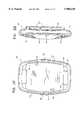
- FIGS. 3A through 3Gare perspective, top plan, bottom plan, front elevation, opposing side elevations and rear elevation views, respectively, of a receiving unit formed in accordance with the present invention
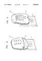
- FIG. 4is a perspective view of a further embodiment of a receiving unit formed in accordance with the present invention.
- FIG. 5is a perspective view of yet another embodiment of a receiving unit formed in accordance with the present invention.
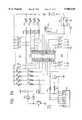
- FIGS. 6A and 6Bis a schematic diagram of a preferred embodiment of a electronic circuit used in a detecting unit formed in accordance with the present invention
- FIGS. 7A and 7Bis a schematic diagram of a preferred embodiment of a electronic circuit used in a receiving unit formed in accordance with the present invention.
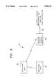
- FIG. 8is a block diagram of a system of the present invention functioning in cooperation with a building security system.
- FIG. 1a system 10 for detecting the existence of a hazardous condition within a building is shown.
- hazardous conditions to be detected by the systemincludes, for example, the presence of smoke, flames, gas or the like.
- the building in which the system 10 is installedmay be any type of building in which the detection of hazardous conditions is critical to saving lives and/or property. While FIG. 1 illustrates the system 10 installed in a residence 2, the building could easily be an office, a factory, etc. Also, the actual positioning of the system, as shown in FIG. 1, within residence 2 is best suited for a smoke detecting system; however, flame or gas detecting system formed in accordance with the present invention may be installed in a different configuration.
- the system 10 of the present inventionbasically includes a plurality of battery-powered detecting units 20 and at least one receiving unit 50. It is to be understood that while only one receiving unit 50 is shown to operate with four detecting units 20, in the context of FIG. 1, it is within the scope of the present invention to have a system with multiple receiving units 50 respectively operating with multiple pluralities of detecting units 20. It is also within the scope of the present invention to form a system with a single receiving unit 50 operating with more than four detecting units 20. More than one of these type systems may also operate together. As exemplified in FIG.
- the system 10is shown to include a first detecting unit 20 mounted in a basement just outside a boiler room 2A, a second detecting unit 20 mounted in a kitchen 2B, a third detecting unit 20 mounted in a downstairs hallway 2C and a fourth detecting unit 20 mounted in an upstairs hallway 2D.
- a receiving unit 50is plugged into an AC outlet 4 in a master bedroom 2E. In this configuration, as will be described in greater detail later, the receiving unit 50 will advantageously alert an owner of the resident sleeping in bedroom 2E, that a hazardous condition has been detected within the residence and, further, the system will inform him or her precisely where the hazardous condition is located.
- FIGS. 2A through 2GA preferred form of the battery-powered detecting unit 20 is shown in FIGS. 2A through 2G.
- the detecting unit 20includes a housing 22 having a cover 24 pivotally attached thereto by a hinge 28.
- a lip 26 on an opposing side of the cover 24serves as a latch for permitting selective opening of cover 24 pivotally on hinge 28.
- the ability to selectively open cover 24permits access to the electronics of the detecting unit 20, which will be discussed in greater detail later.
- the cover 24includes speaker grills 30 formed therein, as best shown in FIGS. 2A and 2E.
- Speaker grills 30serve as openings for an audible warning alarm to be broadcast from detecting unit 20 during the detection of the hazardous condition.
- grills 30also permit smoke, infrared radiation from flames or gas to sufficiently permeate the interior of the units 20 so that such hazardous conditions may be detected and responded to in accordance with the present invention.
- the housing 22further includes vent openings 32 (FIGS. 2A, 2B, 2F and 2G) formed therein. The vent openings 32 are formed in the detecting unit 20 in order to further permit permeation of the elements of the hazardous condition (smoke, radiation and gas) into unit 20.
- the detecting unit 20also preferably includes LED 34, a test pushbutton switch 36 and a hush (reset) pushbutton switch 38 mounted on the cover 24.
- LED 34a test pushbutton switch 36
- a hush (reset) pushbutton switch 38mounted on the cover 24.
- FIG. 2Fa rear view of the detecting unit 20
- two mounting holes 40are provided in housing 22 which permit the unit to be mounted to either a ceiling (as shown in FIG. 1) or a wall within a building.
- FIGS. 3A through 3GA preferred form of a receiving unit 50 is shown in FIGS. 3A through 3G.
- the receiving unit 50includes a housing 52, visual indicator sets 54 through 60 and a speaker grid 62.
- Each visual indicator set, 54 through 60includes a green light emitting diode (LED), 54A through 60A, and a red LED, 54B through 60B.
- each visual indicator set, 54 through 60has a label area, 54C through 60C, positioned between the green and red LEDs for providing an area to designate each set of visual indicators. For example, the name of the room within the residence in which the detecting units are mounted may be written in the label area in order to identify which visual indicator set is associated with which detecting unit (FIGS. 3A and 3D).
- receiving unit 50is preferably powered via AC power provided from AC outlet 4. Accordingly, AC plug 70 is provided on the receiving unit 50, in the rear of housing 52, which engages AC outlet 4. Furthermore, receiving unit 50 includes a vent 72 also formed in the rear of housing 52 (FIG. 3F). Vent 72 permits ventilation for the electronic components contained in the receiving unit 50, which will be described in greater detail later.
- the receiving unitalso includes a hush (reset) pushbutton switch 74 mounted below the sets of visual indicators on housing 52 of the receiving unit. The function of the pushbutton switch 74 will be described below.
- Each battery-powered detecting unit 20contains electronics for generating a battery status signal and a hazardous condition alert signal.
- the battery status signalis generated and transmitted by each detecting unit 20 if the battery (or batteries) which provides power for the electronic components contained therein is at an acceptable voltage level.
- the acceptable voltage levelmay vary depending on the type of battery utilized in the system.
- the battery status signalis preferably periodically generated and transmitted in order to minimize the power drain on the battery powering the detecting unit 20.
- the battery status signalis generated and transmitted approximately every four (4) hours.
- the transmission duration timeis preferably approximately 1 second. It is to be understood that because most detecting units of detection systems are battery-powered, the need to minimize the drain on such batteries is critical. Accordingly, by advantageously transmitting the battery status signal periodically, in accordance with the present invention, a transmitter in the detecting unit need only be operational on a periodic basis, thus conserving power and extending the lifespan of the battery.
- This unique approach of the present inventionis to be contrasted with the prior art system, previously discussed, which includes an RF receiver in the detecting unit for receiving a battery test signal from a remote control unit. In such a conventional detecting unit, it is necessary to keep the receiver continuously powered in order for the receiver to always be ready to receive the battery test signal. Thus, the battery in the conventional detecting unit is continually drained, thereby severely limiting its lifespan.
- the detecting unit 20 of the present inventiongenerates and transmits a hazardous condition alert signal.
- the alert signalis generated if a hazardous condition is detected by the detecting unit 20.
- detecting unit 20is part of a smoke detection system, then smoke permeating through at least one of the vent openings 32 and/or grills 30 causes detecting unit 20 to generate and transmit the hazardous condition alert signal.
- the detecting unit 20is part of a gas, flame (infrared radiation) or other type of detection system, then the permeation of such gas, infrared radiation or the like into detecting unit 20 will cause the alert signal to be generated and transmitted in a similar manner.
- the receiving unit 50receives the battery status signals and the hazardous condition alert signals from each detecting unit 20 cooperatively operating with the receiving unit 50. It is to be appreciated that to distinguish which detecting unit 20 has transmitted which set of signals, each detecting unit 20 preferably encodes the battery status signal and alert signal with an address unique to each detecting unit 20. In addition, because a system may include more than one receiving unit 50, each detecting unit further encodes the signal transmission with an address to uniquely identify which receiving unit is adapted to receive and respond to a particular detecting unit's signals. In the same manner, the detecting unit/receiving unit address is preferably uniquely set within one detecting/receiving system so as not to interfere with a similar system of a neighboring residence.
- the receiving unit 50decodes the encoded signal(s) and thereby determines which detecting unit 20 has transmitted the battery status signal and/or the alert signal.
- Each set of visual indicators, 54 through 60is respectively assigned to correspond with a particular detecting unit 20. Accordingly, if the receiving unit 50 receives a battery status signal from a particular detecting unit 20 within a predetermined time period, the green LED (54A through 60A) of the respective visual indicator will illuminate, thus indicating that the battery in the particular detecting unit 20 is at an acceptable level.
- the receiving unit 50does not receive the battery status signal from a particular detecting unit 20 within the predetermined time period, then the green LED will extinguish and the red LED (54B through 60B) of the particular visual indicator set will illuminate indicating that the battery in the detecting unit 20 is not at an acceptable level and requires replacement.
- the predetermined time periodmay be twelve (12) hours. This means that if the receiving unit 50 does not receive at least one battery status signal within approximately a twelve (12) hour period (a detecting unit 20 preferably transmits a battery status signal approximately once every four hours) then the receiving unit will treat such absence of signal as an indication that the battery in the detecting unit has fallen below an acceptable level.
- a timing arrangementallows for the possibility that a battery status signal may have been sent out by a detecting unit 20 within the predetermined time period but was not properly received by the receiving unit 50. Such a situation may occur due to random RF interference which may interfere with the battery status signal.
- the predetermined time period for receiving the signalincludes a margin of error to attempt to avoid having the system 10 give a false indication that the battery in a particular detecting unit is below the acceptable level when, in actuality, the battery is above the level but a false indication is triggered merely due to the fact that the receiving unit erroneously fails to receive the battery status signal each time it is transmitted.
- the detecting unit 20preferably generates a secondary status signal even after the battery status signal is no longer generated.
- the secondary status signalis preferably generated approximately two weeks after the last battery status signal is transmitted from the detecting unit 20. Similar to the battery status signal, the secondary status signal is transmitted approximately every four hours.
- the detecting unitis still able to generate and transmit the secondary status signal due to the low power requirements associated with the detecting unit and given the fact that, preferably, the battery voltage being below an acceptable level does not necessarily mean that the battery voltage is below an operable level with respect to detecting unit components.
- the secondary status signalis received by the receiving unit and, in response, the receiving unit outputs an audible warning chirp through speaker grill 62.
- the chirp warningis intended to warn the user of the system that the battery has been below the acceptable level for some time and, therefore, the battery in the detecting unit 20 should be replaced as soon as possible.
- each hazardous condition alert signal transmitted by the detecting units 20is received and decoded by the receiving unit 50.
- the receiving unit 50activates the set of visual indicators (54 through 60) corresponding to the detecting unit 20 which detected the hazardous condition such that both LEDs of the particular set of visual indicators begin to flash.
- an audible warningis activated through speaker grill 62 of the receiving unit 50. The audible warning provides further indication that a hazardous condition has been detected by one of the detecting units 20 in the system. It is to be appreciated that a similar audible warning may be provided by detecting unit 20 through speaker grills 30 once a hazardous condition has been detected.
- LED 34 mounted on cover 24 of detecting unit 20preferably flashes when a hazardous condition is detected.
- the receiving unit 50provides an area for designating which set of visual indicators correspond to which detecting unit (i.e., label areas 56C through 60C), a person may quickly determine the specific location of the hazardous condition by simply glancing at the receiving unit 50 to see which set of visual indicators is flashing. In this manner, the person need not waste valuable time in attempting to locate the condition and may instead plan an escape route from the building. Since a set of visual indicators is assigned to a particular detecting unit 20, the name of the room in which that detecting unit 20 is located may be designated on the label area, 54C through 60C, discussed above. For example, as shown on the receiving unit 50 of FIG.
- the visual indicator set 54is labeled “basement”
- the visual indicator set 56is labeled “kitchen”
- the visual indicator set 58is labeled “downstairs hallway”
- the visual indicator set 60is labeled "upstairs hallway”.
- a unique audible warningmay be provided by the receiving unit 50 to audibly distinguish which detecting unit 20 detected the hazardous condition and, thus, transmitted the alert signal.
- the audible warningmay, for example, include a one second beep followed by a one second silent period followed by a continuous repetition of this particular pattern.
- the audible warningmay include, for example, two beeps with a one second silent period followed by a continuous repetition of this particular pattern.
- the other two detecting units designated on the receiving unit 50may provide similar unique audible patterns. In this way, a person need not even glance at the receiving unit 50 to view the flashing LEDs, but rather, can discern the location of the condition merely by listening to the audible warning pattern.
- each detecting unit 20includes a test pushbutton switch 36.
- the test pushbutton switch 36initiates a test of the system 10 such that, when the pushbutton switch 36 is depressed, a test hazard condition alert signal is transmitted to the receiving unit 50.
- the receiving unitreceives the test signal which causes the corresponding set of visual indicators (54 through 60) for the detecting unit 20 being tested to flash as if a hazardous condition has been detected.
- the audible warning associated with the receiving unit 50is sounded through speaker grill 62 of the receiving unit. It is also to be understood that the audible warning generated by the detecting unit 20 is also activated during this test mode and LED 34 mounted on the detecting unit will flash.
- a reset (i.e., hush) functionis preferably provided on each detecting unit 20 and receiving unit 50.
- Pushbutton switch 38 on the detecting unit 20serves to silence the alert condition (i.e., the sounding of the audible warning and flashing LED) when depressed, while the pushbutton switch 74 on the receiving unit 50 serves to silence the receiving unit's audible warning and to cease the flashing of the set of visual indicators (54 through 60).
- the hush featuremay also be activated when the system 10 is providing warnings during the actual detection of a hazardous condition. However, such feature is also useful when the system 10 is set off by a condition which is not necessarily hazardous, e.g., excess smoke from cooking in a kitchen where a detecting unit 20 is installed.
- the detecting unit 20can send a hush signal to the receiving unit 50 when the hush pushbutton switch 38 is depressed at the detecting unit 20.
- the hush signalhas the same effect on the receiving unit 50 that depressing hush pushbutton switch 74 has on the receiving unit.
- the hush signalmay also be used to initially set-up the system, i.e., provide an indication to the receiving unit 50 that the battery voltage is not below the acceptable level without the receiving unit having to wait for the detecting unit to periodically transmit its normal battery status signal indicating the same. This is a useful function for when the system is initially installed in a residence such that the user can immediately cause the receiving unit to indicate whether or not the battery voltage is below the acceptable level.
- FIGS. 4 and 5alternative embodiments of the receiving unit 50 are illustrated.
- a receiving unit 50'is shown in FIG. 4 which is substantially functionally and structurally the same as the receiving unit 50 previously described herein, with the exception that a nightlight 76 is provided thereon.
- the nightlight 76serves to illuminate the immediate area in the vicinity of the receiving unit 50 so that it is possible to more easily read the label areas, 54C through 60C, on the visual indicator sets.
- receiving unit 50'may further include a rechargeable battery as its power source such that the receiving unit 50' may function as a flashlight when removed from the AC outlet 4.
- the receiving unit 50'automatically switches over to the rechargeable battery as its source of power when removed from the AC outlet 4.
- FIG. 5illustrates a receiving unit 50" which is also similar in function and structure to receiving unit 50, but which also has a built-in AC outlet 78 which permits an AC plug from an appliance, for example, to be inserted therein and to draw power from the AC outlet 4 without removing the receiving unit 50" therefrom.
- the detecting unit circuitmay be considered to include three functional subcircuits for performing the various functions described herein. Accordingly, the detecting unit circuit generally includes a sensing circuit, a battery level monitoring circuit and a transmitting circuit. Other electronic components are shown in FIG. 6 which serve peripheral functions and will be discussed, as needed, to explain the novel features of the present invention.
- the sensing circuitgenerally includes a hazardous condition detector S0 and a detector controller U2 operatively coupled thereto. It is to be appreciated that the preferred implementation of the present invention is for smoke detection; therefore, detector S0 and controller U2 are preferably smoke detecting type devices (e.g., ionic type). However, as previously mentioned, such components may be substituted with infrared or gas (e.g., carbon monoxide) detecting devices.
- the sensing circuitalso includes a microcontroller U1 and a voltage detector U6 operatively coupled between controller U2 and microcontroller U1. It is to be appreciated that, as will be explained, the microcontroller U1 is preferably programmed to provide particular functionality in all of the subcircuits of the detecting unit.
- the sensing circuitalso generally includes a buzzer B1 operatively coupled to detector controller U2.
- the battery level monitoring circuitgenerally includes battery BT1 and voltage detector U5 operatively coupled thereto.
- the battery BT1is the source of power for the entire detecting unit 20 and is, therefore, being monitored to determine whether it is above or below an acceptable level.
- the voltage detector U5is operatively coupled to the microcontroller U1 which also functions in the battery monitoring circuit, as will be explained.
- the transmitting circuit of the detecting unitgenerally includes microcontroller U1 operatively coupled to an oscillator XL1, a switch bank S3, a switch bank S4 and an RF module U7.
- Battery BT1which is preferably a +9 VDC battery, is monitored by voltage detector U5.
- Voltage detector U5in response to the voltage level of BT1, generates and provides a discrete signal to microcontroller U1.
- the discrete signalinforms microcontroller U1 whether the battery BT1 is above or below an acceptable voltage level.
- the microcontroller U1monitors the discrete signal sent by the voltage detector U6.
- Oscillator XL1provides a clock signal to microcontroller U1 which microcontroller U1 uses to determine when to generate and transmit a battery status signal to the receiving unit 50. As previously mentioned, it is preferred that a battery status signal be generated and transmitted every 4 hours; thus, oscillator XL1 is chosen to generate a clock signal which provides such required timing. Therefore, in accordance with the clock signal, microcontroller U1 generates the battery status signal if the discrete signal from the voltage detector U5 indicates that the battery BT1 is at an acceptable level.
- the battery status signalis encoded in order for the receiving unit 50 to determine which detecting unit 20 sent the signal. Also, the signal must be further encoded to indicate which receiving unit 50 (in a multiple receiving unit system) is to receive and respond to the battery status signal.
- Switch banks S3 and S4provide such encoding function. Specifically, switches S1 and S2 of switch bank S3 are used to uniquely identify each detecting unit 20 and, therefore, the signals transmitted therefrom. In a preferred system utilizing four detecting units 20 for each receiving unit 50 (FIG. 1), switches S1 and S2 of switch bank S3 may be set to ON or OFF positions, as shown in Table I, to uniquely identify each detecting unit. If more than four detecting units 20 are being operated with a receiving unit 50, it should be understood that more switches may be added to provide for unique identification thereof
- switches A1 through A10 of switch banks S3 and S4are used to uniquely identify the receiving unit 50 with which a particular detecting unit 20 is to operate.
- the positions of switches A1 through A10must be set the same in each of the four detecting units 20 operating with a particular receiving unit 50 (as will be explained, the receiving unit has a similar switch bank to match the address set in the detecting unit).
- a second set of four detecting units and one receiving unitis to be operated within the broadcasting range of a first set, then, while all detecting units and receiving unit in the second set must have the same settings for switches A1 through A10, such settings must be different as compared to the settings of A1 through A10 in the detecting units and receiving unit of the first set. In this manner, only the proper receiving unit 50 will respond to its properly matched detecting units 20.
- microcontroller U1monitors the settings of the switches of switch banks S3 and S4 and, in response, encodes the battery status signal so that it is uniquely identified with respect to the detecting unit and the receiving unit.
- the encoded battery status signalis sent to RF module U7 where it is transmitted from detecting unit 20.
- a hazardous conditionsuch as smoke
- the smokepermeates the speaker grills 30 and/or the vent openings 32 (FIGS. 2A through 2G) and is sensed by hazardous condition (smoke) detector S0.
- the detector controller U2activates buzzer B1 which provides the audible warning, through speaker grills 30, that the hazardous condition has been detected by the detecting unit 20.
- voltage detector U6is monitoring detector controller U2 such that when a hazardous condition is detected by detector S0, voltage detector U6 sends a discrete signal to microcontroller U1 informing U1 of the existence of the condition.
- microcontroller U1In a similar fashion to that described above, microcontroller U1 generates a hazardous condition alert signal which is encoded in the same manner as the battery status signal.
- the battery status signalis periodically generated and transmitted, while the alert signal is generated whenever a hazardous condition is detected. It is possible that both signals are generated within close time proximity to one another such that microcontroller U1 may generate a combined encoded status signal containing both signals.
- RF module U7receives the encoded alert signal from microcontroller U1 and, in response, transmits the signal to receiving unit 50.
- Reset (hush) switch S1(shown as pushbutton 38 in FIG. 2A) is operatively coupled to the microcontroller U1 and provides a reset signal to microcontroller U1 to silence the audible warning provided by the detecting unit and to extinguish LED 34 which flashes when the hazardous condition alert signal is being transmitted.
- a test pushbutton switch S2(shown as pushbutton 36 in FIG. 1) is operatively coupled to the microcontroller U1 and provides a test signal which causes detecting unit 20 to enter a test mode to test its audible warning and to transmit a test hazardous condition alert signal to the receiving unit 50.
- Reset button S1may preferably be able to override (e.g., cease) the test sequence once initiated by depressing test switch S2.
- a voltage regulator U3is included in detecting unit 20 for regulating the operating voltage level provided to microcontroller U1 and RF module U7.
- a third voltage detector U4is included in unit 20 which generates an interrupt signal which is provided to the microcontroller U1. If jumper J1 is closed, microcontroller U1 will go into a rapid test mode upon receipt of the interrupt signal whereby, instead of generating a battery status signal every four hours, the microcontroller U1 will generate a battery status signal in a shorter time period, for example, every 40 seconds.
- This featureis preferably disabled in normal operation mode and is provided basically for system troubleshooting and final production testing purposes. In other words, the user of the system would not ordinarily operate the system in this rapid test mode.
- the receiving unit circuitmay be considered to include four functional subcircuits for performing the various functions described herein. As with the detecting unit circuit, several components overlap in function between subcircuits, e.g., microcontroller U1.
- the receiving unit circuitgenerally includes a receiving circuit, a battery status indicating circuit, a hazardous condition alert circuit and a power supply circuit. Again, other electronic components are shown in FIGS. 7A and 7B which serve peripheral functions and will be discussed, as needed, to explain the novel features of the present invention.
- the power supply circuitincludes AC plug 70 (FIGS. 3A through 3G), capacitors C1 through C3, fuse F1, resistors R1 and R2, thyristor device Z1, diode bridge, D1 through D4, and Zener diode ZD1.
- Such power supply circuitoperates as a conventional full wave bridge rectifier circuit and converts the AC power supplied by the AC outlet 4 (FIG. 3A), in which AC plug 70 is inserted, to a DC voltage, V DD , which is utilized by the electronic components of the receiving unit 50.
- the receiving circuitgenerally includes an RF receiver module U3 operatively coupled to a microcontroller U1, and switch banks S1 and S2 also operatively coupled to the microcontroller U1.
- microcontroller U1 in receiving unit 50is preferably programmed to provide particular functionality in the receiving, battery level indicating and hazardous condition alert circuits.
- the battery status indicating circuitgenerally includes microcontroller U1, diodes D5 through D12 operatively coupled to microcontroller U1 through resistors R6 through R13, a buzzer B1 and a coil L1 operatively coupled through a transistor Q2 to microcontroller U1.
- the battery status indicating circuitalso includes oscillator XL1 operatively coupled to microcontroller U1.
- the hazardous condition alert circuitgenerally consists of microcontroller U1 and buzzer B1 and coil L1 operatively coupled to microcontroller U1 through transistor Q2.
- RF module U3receives an encoded battery status signal from one of the detecting units 20.
- the received signalis provided to the microcontroller U1 wherein, in accordance with the settings of switch banks S1 and S2, the signal is decoded.
- Microcontroller U1will only respond to signals which are encoded by detecting units 20 in which the settings of switches A1 through A10 of switch banks S3 and S4 (FIG. 6) are set the same way as switches A1 through A10 of switch banks S1 and S2 in receiving unit 50.
- this unique address matching schemeis provided to permit multiple systems (e.g., two systems having one receiving unit and four detecting units) to operate within a common RF broadcasting area.
- microcontroller U1determines that it is the receiving unit set to receive the signal, microcontroller U1 further decodes the received signal to determine which of the four detecting units sent the signal. As previously explained, such identification is uniquely set by switches S1 and S2 of switch bank S3 of the detecting unit 20.
- LED's D5 through D12comprise the visual indicator sets 54 through 60 (FIGS. 3A through 3G).
- D5is a red LED (54B) and D9 is a green LED (54A) and together they make up visual indicator set 54.
- D6red LED 56B
- D10green LED 56A
- D7red LED 58B
- D11green LED 58A
- D8red LED 60B
- D12green LED 60A
- Microcontroller U1assigns one of the four visual indicator sets, 54 through 60, to one of the four detecting units 20 and can determine which detecting unit 20 sent which signal by decoding the two bit address encoded in the signal by switches S1 and S2 of switchbank S3 of the detecting unit 20. Furthermore, switches S1 and S2 of switchbank S1 of the receiving unit 50 may be utilized to selectively disable each set of visual indicators which is not assigned to a particular detecting unit, e.g., in a system with less than four detecting units in operation.
- the switches S1 and S2 of switch bank S1(FIGS. 7A and 7B) may be set as shown in Table II, depending on how many detecting units 20 are operating with the receiving unit 50. If more than four detecting units 20 are being operated with a receiving unit 50, then more switches may be provided to selectively control the activation of their respective visual indicator sets.
- microcontroller U1receives the battery status signals through RF module U3 and, via their unique addresses, decodes the signals and then respectively illuminates each green LED (D9 through D12) if a battery status signal is received for that particular detecting unit 20. If a battery status signal is not received from a particular detecting unit 20 within a predetermined time period (set by a clock signal generated by oscillator XL1), then microcontroller U1 will extinguish the corresponding green LED and illuminate the corresponding red LED. As previously mentioned, the predetermined time period is preferably 12 hours. In this manner, a person need only glance at the receiving unit 50 to determine if the green LED or red LED is illuminated for a particular detecting unit 20. If the red LED is illuminated, he will know to change the battery in the corresponding detecting unit 20.
- RF module U3may receive a hazardous condition alert signal transmitted by one of the four detecting units 20.
- the microcontroller U1decodes the signal and, based on whether or not there is an address match between switches A1 through A10 of the detecting and receiving units, the microcontroller U1 will further decode the signal to determine from which detecting unit the signal was transmitted.
- the microcontroller U1causes the set of visual indicators (56 through 60) corresponding to the detecting unit 20 that sent the hazardous condition alert signal to continually flash. This visual warning gives a person an indication as to which detecting unit 20 detected the condition and, thus, gives him an opportunity to act accordingly.
- microcontroller U1activates buzzer B1 through transistor Q2 and coil L1. Similar to buzzer B1 in detecting unit 20, buzzer B1 in receiving unit 50 sounds an audible warning when an alert signal is received. Also, in a preferred embodiment, microcontroller U1 may cause buzzer B1 to sound a unique warning pattern depending on which detecting unit 20 detected the hazardous condition.
- hush (reset) pushbutton switch 74is not expressly shown in FIGS. 7A and 7B, it is to be appreciated that such switch operates in a similar manner to the reset switch S1 (pushbutton 38) shown in FIGS. 6A and 6B for the detecting unit, i.e., depressing reset pushbutton ceases alarm condition and, therefore, ceases flashing visual indicators and silences buzzer B1.
- a hush pushbutton switchmay be included on the detecting unit 20 only and, when depressed, the detecting unit 20 transmits a reset signal, encoded in the manner described herein, to reset the receiving unit 50.
- Voltage detector U2shown in FIGS. 7A and 7B operatively coupled to microcontroller U1, is preferably provided to generate a microcontroller reset signal upon power-up of the receiving unit 50, e.g., when the unit is plugged into AC outlet 4.
- the microcontroller reset signalresets the microcontroller U1 upon power-up.
- a parts list for the detecting circuit in FIGS. 6A and 6Bis provided below in Table III, while a parts list for the receiving circuit in FIGS. 7A and 7B is provided below in Table IV. Additionally, the pin name designations on the integrated circuits in FIGS. 6A, 6B, 7A and 7B relate to parts specified in the parts list. It is envisioned that components comparable to those listed below, connected differently from that shown in FIGS. 6A, 6B, 7A and 7B, may be suitable to practice the present invention.
- a system 10'is formed by at least one detecting unit 20, at least one receiving unit 50 and a building security system 80.
- the at least one detecting unit 20transmits a hazardous condition alert signal to the building security system 80 in addition to the receiving unit 50 as described herein.
- the security system 80may serve the primary purpose of alerting a security system monitoring company or local authorities of an intruder or other security condition over telephone line 82.
- the security system 80also preferably includes receiving means similar to the at least one receiving unit 50 which receives the hazardous condition alert signal from the at least one detecting unit 20.
- the security system 80may then communicate the existence of the hazardous condition within the building in which the system 10' is operating to the monitoring company and/or local authorities over line 82. In this manner, the present invention provides a passive system for detecting hazardous conditions and automatically reporting their existence to emergency personnel. It is to be understood that security system 80 may preferably be responsive to all detecting units 20 within a building whether or not the detecting units 20 cooperate with different receiving units 50.
Landscapes
- Engineering & Computer Science (AREA)
- Computer Security & Cryptography (AREA)
- Physics & Mathematics (AREA)
- General Physics & Mathematics (AREA)
- Alarm Systems (AREA)
- Fire Alarms (AREA)
- Emergency Alarm Devices (AREA)
- Selective Calling Equipment (AREA)
- Burglar Alarm Systems (AREA)
- Tests Of Electric Status Of Batteries (AREA)
Abstract
Description
1. Field of the Invention
The present invention relates to remote detecting systems and methods, and more particularly relates to remote detecting systems and methods for detecting hazardous conditions and the like.
2. Description of the Prior Art
It is well know that many battery-operated smoke detectors (as well as other similar detectors for detecting hazardous conditions such as flames from a fire or gas build-ups and leaks, e.g., carbon monoxide) installed in homes and businesses are rendered inoperable due to weak or disconnected batteries. Despite local and state fire authorities encouraging periodic testing of the batteries, many detectors are unfortunately rendered inoperative simply because owners are either unfamiliar with or unwilling to perform the maintenance procedures developed by existing detector manufacturers to test the batteries.
For example, one such conventional maintenance procedure for testing a detector battery on a ceiling mounted detector encompasses reaching up, sometimes with the aid of a broomstick, and depressing a button that activates the alarm buzzer. The alarm buzzer, by design, produces a loud piercing shriek that can be quite unpleasant especially when the detector is within arm's length. Other conventional detectors have attempted to overcome the need to actively test a detector by developing a detector which provides an audible "chirp" to alert the user that the strength of the battery is getting low. However, this chirping is so annoying that many owners disconnect the battery once they hear the audible warning and attempt to remember to replace the battery when they get a chance. Even the most diligent owners who periodically test the battery will realize that the act of testing the battery will cause the batteries life to be shortened. Also, in detectors with an audible low battery's warning, it is known that the chirping will cause the battery to be short lived.
Further attempts to make testing detector batteries more convenient have included systems which employ remote controlled testing features. One conventional approach uses the light beam from a flashlight to activate the alarm and, thus, test the battery. In such detectors, it is also suggested to use the flashlight to silence an alarm that has been inadvertently set off, as by cooking or smoking. However, such approach assumes that an operable flashlight is always handy, which is usually not the case. Still further, it is also known that, in place of the light beam of a flashlight activating the battery test in a detector, a radio frequency (RF) signal from a handheld remote control unit, directed at the detector, can be transmitted to the detector to activate the test procedure. However, a detector which operates with the remotely transmitted RF signal must continuously be ready to receive the RF test signal at all times. Such a continuously operating receiver in the detector disadvantageously drains the detector battery.
Another limit on the reliability of battery operated smoke detectors is associated with the fact that a detector whose alarm has been set off by a hazardous condition in the room in which it is installed may not be heard by a person in a distant room, e.g., an alarm in the basement may not be heard by someone sleeping on the third floor. Even if a distant alarm is heard, it is not always discernible as to the location of the sound and the possible dangerous condition (e.g., smoke from a fire) and, as a result, valuable time is lost in roaming around until the location is discovered. By the time other evidence of the hazardous condition is noticed (e.g., flames from a fire), critical time for deciding an escape route has already been wasted.
It is an object of the present invention to provide remote detecting systems and methods which overcome the inherent disadvantages of battery-powered detectors which detect the existence of hazardous conditions such as smoke, flames, gases and the like.
It is another object of the present invention to provide remote detecting systems and methods which provide substantial improvement in the reliability of such detectors by utilizing a remote receiver to continuously indicate a battery status of a plurality of detecting units requiring only visual interaction by the user.
It is yet another object of the present invention to provide remote detecting systems and methods which includes a receiver/indicator unit that more directly alerts the user to a hazardous condition.
It is a further object of the invention to provide remote detecting systems and methods which include a receiver having a display that provides valuable information regarding the location of the hazardous condition enabling the user to quickly decide a course of action.
In accordance with one form of the present invention, a system for detecting the existence of a hazardous condition in an area includes at least one battery-powered detecting unit which is located within the area for detecting the existence of the hazardous condition. The battery-powered detecting unit generates and transmits a battery status signal in response to the battery being at an acceptable level. Further, the system includes at least one receiving unit which is responsive to the battery status signal such that the receiving unit provides at least one sensory indication when the battery status signal is not received. In this manner, the status of the battery is passively and continuously monitored thereby relieving an owner of the task of activating a test procedure himself.
In a preferred embodiment, the system includes a plurality of battery-powered detecting units (e.g., four) which are respectively located within a plurality of zones within an area (e.g., a residence or office building) such that each detecting unit generates and transmits its own battery status signal to the receiving unit. The receiving unit then responsively provides one of a plurality of sensory indications when one of the plurality of battery status signals is not respectively received. Still further, in a preferred form of the present invention, the receiving unit provides a first sensory indication when the battery status signal is received and a second sensory indication when the battery status signal is not received. The first sensory indication may be provided by a first indicator which, preferably, is a green light emitting diode. Similarly, the second sensory indication may be provided by a second indicator which, preferably, is a red light emitting diode. It is to be understood that, preferably, each detecting unit only periodically generates and transmits a battery status signal (e.g., every four hours). In this way, the transmitting circuit used to transmit the signal need only be active at the time the unit is transmitting a signal. Therefore, there is less of a drain on the battery as compared to conventional units which require constantly active components. Also, it is preferred that the receiving unit, which is preferably continuously powered via AC power from an AC outlet, only activate the visual indicators to indicate the absence of a battery status signal after a predetermined time period has elapsed (e.g., 12 hours) in which no signal has been received.
It is to be appreciated that the at least one sensory indication provided by the receiving unit may also provide an indication that the detecting unit has detected a hazardous condition. Such additional indication may be provided visually through the first and second indicators (e.g., flashing the LEDs), described above, or through an audible indicator (e.g., speaker or buzzer). Furthermore, even when the battery voltage in the detecting unit is below an acceptable level, it is to be appreciated that the transmitting circuit in the detecting unit is still able to transmit the hazardous condition alert signal to the receiving unit due to the preferably low power requirements associated with the transmitting circuit.
In a further preferred embodiment of the present invention, despite the fact that the battery voltage in the detecting unit is below the acceptable level, the detecting unit may generate and transmit a secondary status signal. The detecting unit is still able to generate and transmit the secondary status signal due to the low power requirements of the transmitting circuit. The secondary status signal is preferably generated a certain time (e.g., approximately two weeks) after the battery status signal is no longer transmitted and, once transmission begins, the secondary status signal is preferably retransmitted periodically (e.g., approximately every four hours). The receiving unit receives the secondary status signal and, in response, activates the audible indicator to provide a "chirp" warning sound. In this way, if a person fails to see that the receiving unit is giving a battery low visual indication, the receiving unit will provide an audible warning to the person to indicate that the battery needs replacement. It is to be appreciated that generation of the chirp is provided by the receiving unit which is preferably powered via an AC outlet and, therefore, does not put an additional drain on the detecting unit battery.
Both the battery-powered detecting unit and the receiving unit of the system of the present invention may include means for silencing the audible indicator (e.g., hush buttons) as well as the visual indicators activated during the detection of the existence of a hazardous condition.
In yet another form of the present invention, the receiving unit may include a lamp, (e.g., a nightlight) for illuminating an area in the vicinity of the receiving unit. Also, as previously mentioned, the receiving unit is preferably adapted to be powered via AC power provided by an AC power outlet. As an alternative, a rechargeable battery may be provided in the receiving unit as a source of power for the unit. In this manner, the receiving unit with the lamp, driven by the rechargeable battery, may be used as a portable light source (e.g., flashlight).
In accordance with a method for monitoring a voltage level associated with a battery of a battery-powered detecting unit, the method includes the steps of generating a battery status signal when the battery in the detecting unit is at an acceptable level and then transmitting the battery status signal from the detecting unit. The method further includes monitoring the battery status signal at a receiving unit, the receiving unit including a sensory indicator. Lastly, the method includes activating the sensory indicator when the battery status signal is not received by the receiving unit.
Accordingly, the present invention provides a system for remotely monitoring the status of a battery used to power a detecting unit mounted on a ceiling or wall within a residence or office building. The system of the present invention also provides for the ability to detect and monitor the existence of a hazardous condition in an area within the vicinity of the detecting unit and to be able to determine the precise location of the hazardous condition while remaining a safe distance from the hazardous condition. Such remote detecting and monitoring provides a person in a residence or building in which a hazardous condition exists with more time to plan an escape route from the residence or building.
Furthermore, the detector system of the present invention overcomes the inherent disadvantages of conventional battery-operated detectors, as described above, by offering continuous passive monitoring of a plurality of detecting units from a centrally located receiving unit. The receiving unit receives a periodic battery status signal from each detecting unit. A transmitting circuit located within the detecting unit sends a radio frequency signal to a receiving unit that is conveniently located to alert the home owner of the battery status and also signal a visual and/or an audio alarm to alert the owner in the case of an alarm condition in any of a multitude of detecting zones.
These and other objects, features and advantages of the present invention will become apparent from the following detailed description of illustrative embodiments thereof, which is to be read in connection with the accompanying drawings.
FIG. 1 is a pictorial, cross sectional view of a residence having a system formed in accordance with the present invention installed therein;
FIGS. 2A through 2G are perspective, opposing side elevations, bottom plan, front elevation, rear elevation and top plan views, respectively, of a detecting unit formed in accordance with the present invention;
FIGS. 3A through 3G are perspective, top plan, bottom plan, front elevation, opposing side elevations and rear elevation views, respectively, of a receiving unit formed in accordance with the present invention;
FIG. 4 is a perspective view of a further embodiment of a receiving unit formed in accordance with the present invention;
FIG. 5 is a perspective view of yet another embodiment of a receiving unit formed in accordance with the present invention;
FIGS. 6A and 6B is a schematic diagram of a preferred embodiment of a electronic circuit used in a detecting unit formed in accordance with the present invention;
FIGS. 7A and 7B is a schematic diagram of a preferred embodiment of a electronic circuit used in a receiving unit formed in accordance with the present invention; and
FIG. 8 is a block diagram of a system of the present invention functioning in cooperation with a building security system.
Referring initially to FIG. 1, asystem 10 for detecting the existence of a hazardous condition within a building is shown. It is to be appreciated that such hazardous conditions to be detected by the system includes, for example, the presence of smoke, flames, gas or the like. The building in which thesystem 10 is installed may be any type of building in which the detection of hazardous conditions is critical to saving lives and/or property. While FIG. 1 illustrates thesystem 10 installed in aresidence 2, the building could easily be an office, a factory, etc. Also, the actual positioning of the system, as shown in FIG. 1, withinresidence 2 is best suited for a smoke detecting system; however, flame or gas detecting system formed in accordance with the present invention may be installed in a different configuration. Nonetheless, it is the unique cooperation between the components of the present invention, which will be described herein, rather than their precise location within a building, that provides one of the advantages that the present invention has over the prior art. However, the ability to place the detecting unit of the present invention in places within the building which are substantially inaccessible or difficult to get to (e.g., attics) provides a further advantage over conventional detecting units which must be substantially accessible in order to test the battery therein.
Thesystem 10 of the present invention basically includes a plurality of battery-powered detectingunits 20 and at least one receivingunit 50. It is to be understood that while only one receivingunit 50 is shown to operate with four detectingunits 20, in the context of FIG. 1, it is within the scope of the present invention to have a system with multiple receivingunits 50 respectively operating with multiple pluralities of detectingunits 20. It is also within the scope of the present invention to form a system with asingle receiving unit 50 operating with more than four detectingunits 20. More than one of these type systems may also operate together. As exemplified in FIG. 1, thesystem 10 is shown to include a first detectingunit 20 mounted in a basement just outside aboiler room 2A, a second detectingunit 20 mounted in akitchen 2B, a third detectingunit 20 mounted in adownstairs hallway 2C and a fourth detectingunit 20 mounted in anupstairs hallway 2D. Also, a receivingunit 50 is plugged into anAC outlet 4 in amaster bedroom 2E. In this configuration, as will be described in greater detail later, the receivingunit 50 will advantageously alert an owner of the resident sleeping inbedroom 2E, that a hazardous condition has been detected within the residence and, further, the system will inform him or her precisely where the hazardous condition is located.
A preferred form of the battery-powered detectingunit 20 is shown in FIGS. 2A through 2G. The detectingunit 20 includes ahousing 22 having acover 24 pivotally attached thereto by ahinge 28. Alip 26 on an opposing side of thecover 24 serves as a latch for permitting selective opening ofcover 24 pivotally onhinge 28. The ability to selectivelyopen cover 24 permits access to the electronics of the detectingunit 20, which will be discussed in greater detail later.
Thecover 24 includes speaker grills 30 formed therein, as best shown in FIGS. 2A and 2E. Speaker grills 30 serve as openings for an audible warning alarm to be broadcast from detectingunit 20 during the detection of the hazardous condition. However, grills 30 also permit smoke, infrared radiation from flames or gas to sufficiently permeate the interior of theunits 20 so that such hazardous conditions may be detected and responded to in accordance with the present invention. Thehousing 22 further includes vent openings 32 (FIGS. 2A, 2B, 2F and 2G) formed therein. Thevent openings 32 are formed in the detectingunit 20 in order to further permit permeation of the elements of the hazardous condition (smoke, radiation and gas) intounit 20.
Further, the detectingunit 20 also preferably includesLED 34, atest pushbutton switch 36 and a hush (reset)pushbutton switch 38 mounted on thecover 24. The functions of these controls will be explained during the explanation of the basic operation of the present invention to follow. Also, as shown in FIG. 2F (a rear view of the detecting unit 20), two mountingholes 40 are provided inhousing 22 which permit the unit to be mounted to either a ceiling (as shown in FIG. 1) or a wall within a building.
A preferred form of a receivingunit 50 is shown in FIGS. 3A through 3G. The receivingunit 50 includes ahousing 52, visual indicator sets 54 through 60 and aspeaker grid 62. Each visual indicator set, 54 through 60, includes a green light emitting diode (LED), 54A through 60A, and a red LED, 54B through 60B. Also, each visual indicator set, 54 through 60, has a label area, 54C through 60C, positioned between the green and red LEDs for providing an area to designate each set of visual indicators. For example, the name of the room within the residence in which the detecting units are mounted may be written in the label area in order to identify which visual indicator set is associated with which detecting unit (FIGS. 3A and 3D).
As shown in FIGS. 1 and 3A, receivingunit 50 is preferably powered via AC power provided fromAC outlet 4. Accordingly, AC plug 70 is provided on the receivingunit 50, in the rear ofhousing 52, which engagesAC outlet 4. Furthermore, receivingunit 50 includes avent 72 also formed in the rear of housing 52 (FIG. 3F).Vent 72 permits ventilation for the electronic components contained in the receivingunit 50, which will be described in greater detail later. The receiving unit also includes a hush (reset)pushbutton switch 74 mounted below the sets of visual indicators onhousing 52 of the receiving unit. The function of thepushbutton switch 74 will be described below.
The basis operation ofsystem 10 of the present invention will now be explained, followed by a detailed description of a preferred implementation of the detectingunit 20 and the receivingunit 50. Each battery-powered detectingunit 20 contains electronics for generating a battery status signal and a hazardous condition alert signal. The battery status signal is generated and transmitted by each detectingunit 20 if the battery (or batteries) which provides power for the electronic components contained therein is at an acceptable voltage level. The acceptable voltage level may vary depending on the type of battery utilized in the system.
The battery status signal is preferably periodically generated and transmitted in order to minimize the power drain on the battery powering the detectingunit 20. In a preferred embodiment, the battery status signal is generated and transmitted approximately every four (4) hours. The transmission duration time is preferably approximately 1 second. It is to be understood that because most detecting units of detection systems are battery-powered, the need to minimize the drain on such batteries is critical. Accordingly, by advantageously transmitting the battery status signal periodically, in accordance with the present invention, a transmitter in the detecting unit need only be operational on a periodic basis, thus conserving power and extending the lifespan of the battery. This unique approach of the present invention is to be contrasted with the prior art system, previously discussed, which includes an RF receiver in the detecting unit for receiving a battery test signal from a remote control unit. In such a conventional detecting unit, it is necessary to keep the receiver continuously powered in order for the receiver to always be ready to receive the battery test signal. Thus, the battery in the conventional detecting unit is continually drained, thereby severely limiting its lifespan.
In addition to the battery status signal, the detectingunit 20 of the present invention generates and transmits a hazardous condition alert signal. The alert signal is generated if a hazardous condition is detected by the detectingunit 20. Specifically, if detectingunit 20 is part of a smoke detection system, then smoke permeating through at least one of thevent openings 32 and/or grills 30causes detecting unit 20 to generate and transmit the hazardous condition alert signal. Furthermore, if the detectingunit 20 is part of a gas, flame (infrared radiation) or other type of detection system, then the permeation of such gas, infrared radiation or the like into detectingunit 20 will cause the alert signal to be generated and transmitted in a similar manner. The receivingunit 50 receives the battery status signals and the hazardous condition alert signals from each detectingunit 20 cooperatively operating with the receivingunit 50. It is to be appreciated that to distinguish which detectingunit 20 has transmitted which set of signals, each detectingunit 20 preferably encodes the battery status signal and alert signal with an address unique to each detectingunit 20. In addition, because a system may include more than one receivingunit 50, each detecting unit further encodes the signal transmission with an address to uniquely identify which receiving unit is adapted to receive and respond to a particular detecting unit's signals. In the same manner, the detecting unit/receiving unit address is preferably uniquely set within one detecting/receiving system so as not to interfere with a similar system of a neighboring residence.
In turn, the receivingunit 50 decodes the encoded signal(s) and thereby determines which detectingunit 20 has transmitted the battery status signal and/or the alert signal. Each set of visual indicators, 54 through 60, is respectively assigned to correspond with a particular detectingunit 20. Accordingly, if the receivingunit 50 receives a battery status signal from a particular detectingunit 20 within a predetermined time period, the green LED (54A through 60A) of the respective visual indicator will illuminate, thus indicating that the battery in the particular detectingunit 20 is at an acceptable level. However, if the receivingunit 50 does not receive the battery status signal from a particular detectingunit 20 within the predetermined time period, then the green LED will extinguish and the red LED (54B through 60B) of the particular visual indicator set will illuminate indicating that the battery in the detectingunit 20 is not at an acceptable level and requires replacement.
In a preferred embodiment, the predetermined time period may be twelve (12) hours. This means that if the receivingunit 50 does not receive at least one battery status signal within approximately a twelve (12) hour period (a detectingunit 20 preferably transmits a battery status signal approximately once every four hours) then the receiving unit will treat such absence of signal as an indication that the battery in the detecting unit has fallen below an acceptable level. Such a timing arrangement allows for the possibility that a battery status signal may have been sent out by a detectingunit 20 within the predetermined time period but was not properly received by the receivingunit 50. Such a situation may occur due to random RF interference which may interfere with the battery status signal. Thus, the predetermined time period for receiving the signal includes a margin of error to attempt to avoid having thesystem 10 give a false indication that the battery in a particular detecting unit is below the acceptable level when, in actuality, the battery is above the level but a false indication is triggered merely due to the fact that the receiving unit erroneously fails to receive the battery status signal each time it is transmitted.
As previously mentioned, the detectingunit 20 preferably generates a secondary status signal even after the battery status signal is no longer generated. The secondary status signal is preferably generated approximately two weeks after the last battery status signal is transmitted from the detectingunit 20. Similar to the battery status signal, the secondary status signal is transmitted approximately every four hours. Despite the fact that the battery voltage is below the acceptable level, the detecting unit is still able to generate and transmit the secondary status signal due to the low power requirements associated with the detecting unit and given the fact that, preferably, the battery voltage being below an acceptable level does not necessarily mean that the battery voltage is below an operable level with respect to detecting unit components.
The secondary status signal is received by the receiving unit and, in response, the receiving unit outputs an audible warning chirp throughspeaker grill 62. The chirp warning is intended to warn the user of the system that the battery has been below the acceptable level for some time and, therefore, the battery in the detectingunit 20 should be replaced as soon as possible.
In a similar fashion, each hazardous condition alert signal transmitted by the detectingunits 20 is received and decoded by the receivingunit 50. In response to the receipt of an alert signal, the receivingunit 50 activates the set of visual indicators (54 through 60) corresponding to the detectingunit 20 which detected the hazardous condition such that both LEDs of the particular set of visual indicators begin to flash. Furthermore, in addition to the visual indication provided by the flashing LEDs, an audible warning is activated throughspeaker grill 62 of the receivingunit 50. The audible warning provides further indication that a hazardous condition has been detected by one of the detectingunits 20 in the system. It is to be appreciated that a similar audible warning may be provided by detectingunit 20 through speaker grills 30 once a hazardous condition has been detected. Also,LED 34 mounted oncover 24 of detectingunit 20 preferably flashes when a hazardous condition is detected.
Advantageously, since the receivingunit 50 provides an area for designating which set of visual indicators correspond to which detecting unit (i.e.,label areas 56C through 60C), a person may quickly determine the specific location of the hazardous condition by simply glancing at the receivingunit 50 to see which set of visual indicators is flashing. In this manner, the person need not waste valuable time in attempting to locate the condition and may instead plan an escape route from the building. Since a set of visual indicators is assigned to a particular detectingunit 20, the name of the room in which that detectingunit 20 is located may be designated on the label area, 54C through 60C, discussed above. For example, as shown on the receivingunit 50 of FIG. 3A, the visual indicator set 54 is labeled "basement", the visual indicator set 56 is labeled "kitchen", the visual indicator set 58 is labeled "downstairs hallway", and the visual indicator set 60 is labeled "upstairs hallway". Thus, the owner of the residence or any person therein may quickly determine where the hazardous condition is located by reading the label next to the flashing visual indicators.
Further, in a preferred embodiment, a unique audible warning may be provided by the receivingunit 50 to audibly distinguish which detectingunit 20 detected the hazardous condition and, thus, transmitted the alert signal. For example, referring to FIGS. 1 and 3A, if the detectingunit 20 in thebasement 2A detected the hazardous condition and transmitted an alert signal to the receivingunit 50, the audible warning may, for example, include a one second beep followed by a one second silent period followed by a continuous repetition of this particular pattern. On the other hand, if the detecting unit in thekitchen 2B detects the condition and transmits an alert signal, the audible warning may include, for example, two beeps with a one second silent period followed by a continuous repetition of this particular pattern. In a similar manner, the other two detecting units designated on the receivingunit 50, in FIG. 3A, may provide similar unique audible patterns. In this way, a person need not even glance at the receivingunit 50 to view the flashing LEDs, but rather, can discern the location of the condition merely by listening to the audible warning pattern.
Furthermore, as previously mentioned, each detectingunit 20 includes atest pushbutton switch 36. Thetest pushbutton switch 36 initiates a test of thesystem 10 such that, when thepushbutton switch 36 is depressed, a test hazard condition alert signal is transmitted to the receivingunit 50. The receiving unit receives the test signal which causes the corresponding set of visual indicators (54 through 60) for the detectingunit 20 being tested to flash as if a hazardous condition has been detected. Also, the audible warning associated with the receivingunit 50 is sounded throughspeaker grill 62 of the receiving unit. It is also to be understood that the audible warning generated by the detectingunit 20 is also activated during this test mode andLED 34 mounted on the detecting unit will flash. A reset (i.e., hush) function is preferably provided on each detectingunit 20 and receivingunit 50.Pushbutton switch 38 on the detectingunit 20 serves to silence the alert condition (i.e., the sounding of the audible warning and flashing LED) when depressed, while thepushbutton switch 74 on the receivingunit 50 serves to silence the receiving unit's audible warning and to cease the flashing of the set of visual indicators (54 through 60). It is to be understood that the hush feature may also be activated when thesystem 10 is providing warnings during the actual detection of a hazardous condition. However, such feature is also useful when thesystem 10 is set off by a condition which is not necessarily hazardous, e.g., excess smoke from cooking in a kitchen where a detectingunit 20 is installed.
In an alternative preferred embodiment, the detectingunit 20 can send a hush signal to the receivingunit 50 when thehush pushbutton switch 38 is depressed at the detectingunit 20. The hush signal has the same effect on the receivingunit 50 that depressinghush pushbutton switch 74 has on the receiving unit. Still further, the hush signal may also be used to initially set-up the system, i.e., provide an indication to the receivingunit 50 that the battery voltage is not below the acceptable level without the receiving unit having to wait for the detecting unit to periodically transmit its normal battery status signal indicating the same. This is a useful function for when the system is initially installed in a residence such that the user can immediately cause the receiving unit to indicate whether or not the battery voltage is below the acceptable level.
Referring now to FIGS. 4 and 5, alternative embodiments of the receivingunit 50 are illustrated. Particularly, a receiving unit 50' is shown in FIG. 4 which is substantially functionally and structurally the same as the receivingunit 50 previously described herein, with the exception that a nightlight 76 is provided thereon. Because the receiving unit 50' plugs into anAC outlet 4, the nightlight 76 serves to illuminate the immediate area in the vicinity of the receivingunit 50 so that it is possible to more easily read the label areas, 54C through 60C, on the visual indicator sets. It is also to be appreciated that receiving unit 50' may further include a rechargeable battery as its power source such that the receiving unit 50' may function as a flashlight when removed from theAC outlet 4. Preferably, the receiving unit 50' automatically switches over to the rechargeable battery as its source of power when removed from theAC outlet 4.
Still further, FIG. 5 illustrates a receivingunit 50" which is also similar in function and structure to receivingunit 50, but which also has a built-inAC outlet 78 which permits an AC plug from an appliance, for example, to be inserted therein and to draw power from theAC outlet 4 without removing the receivingunit 50" therefrom.
Referring now to FIGS. 6A and 6B, a preferred implementation of a circuit for performing the functions of the detectingunit 20 is shown. The detecting unit circuit may be considered to include three functional subcircuits for performing the various functions described herein. Accordingly, the detecting unit circuit generally includes a sensing circuit, a battery level monitoring circuit and a transmitting circuit. Other electronic components are shown in FIG. 6 which serve peripheral functions and will be discussed, as needed, to explain the novel features of the present invention.
The sensing circuit generally includes a hazardous condition detector S0 and a detector controller U2 operatively coupled thereto. It is to be appreciated that the preferred implementation of the present invention is for smoke detection; therefore, detector S0 and controller U2 are preferably smoke detecting type devices (e.g., ionic type). However, as previously mentioned, such components may be substituted with infrared or gas (e.g., carbon monoxide) detecting devices. The sensing circuit also includes a microcontroller U1 and a voltage detector U6 operatively coupled between controller U2 and microcontroller U1. It is to be appreciated that, as will be explained, the microcontroller U1 is preferably programmed to provide particular functionality in all of the subcircuits of the detecting unit. The sensing circuit also generally includes a buzzer B1 operatively coupled to detector controller U2.
On the other hand, the battery level monitoring circuit generally includes battery BT1 and voltage detector U5 operatively coupled thereto. The battery BT1 is the source of power for the entire detectingunit 20 and is, therefore, being monitored to determine whether it is above or below an acceptable level. The voltage detector U5 is operatively coupled to the microcontroller U1 which also functions in the battery monitoring circuit, as will be explained. Lastly, the transmitting circuit of the detecting unit generally includes microcontroller U1 operatively coupled to an oscillator XL1, a switch bank S3, a switch bank S4 and an RF module U7.
The operation of the detectingunit 20, in the context of the preferred circuit implementation of FIGS. 6A and 6B, will now be described. Battery BT1, which is preferably a +9 VDC battery, is monitored by voltage detector U5. Voltage detector U5, in response to the voltage level of BT1, generates and provides a discrete signal to microcontroller U1. The discrete signal informs microcontroller U1 whether the battery BT1 is above or below an acceptable voltage level. The microcontroller U1 monitors the discrete signal sent by the voltage detector U6.
Oscillator XL1 provides a clock signal to microcontroller U1 which microcontroller U1 uses to determine when to generate and transmit a battery status signal to the receivingunit 50. As previously mentioned, it is preferred that a battery status signal be generated and transmitted every 4 hours; thus, oscillator XL1 is chosen to generate a clock signal which provides such required timing. Therefore, in accordance with the clock signal, microcontroller U1 generates the battery status signal if the discrete signal from the voltage detector U5 indicates that the battery BT1 is at an acceptable level.
However, as previously mentioned, the battery status signal is encoded in order for the receivingunit 50 to determine which detectingunit 20 sent the signal. Also, the signal must be further encoded to indicate which receiving unit 50 (in a multiple receiving unit system) is to receive and respond to the battery status signal. Switch banks S3 and S4 provide such encoding function. Specifically, switches S1 and S2 of switch bank S3 are used to uniquely identify each detectingunit 20 and, therefore, the signals transmitted therefrom. In a preferred system utilizing four detectingunits 20 for each receiving unit 50 (FIG. 1), switches S1 and S2 of switch bank S3 may be set to ON or OFF positions, as shown in Table I, to uniquely identify each detecting unit. If more than four detectingunits 20 are being operated with a receivingunit 50, it should be understood that more switches may be added to provide for unique identification thereof
TABLE I______________________________________ SWITCH S1 OF SWITCH S2 OFDETECTING UNIT # SWITCH BANK S3 SWITCH BANK S3______________________________________1 ONON 2 OFF ON3 ONOFF 4 OFF OFF______________________________________
On the other hand, switches A1 through A10 of switch banks S3 and S4 are used to uniquely identify the receivingunit 50 with which a particular detectingunit 20 is to operate. In other words, the positions of switches A1 through A10 (ON or OFF) must be set the same in each of the four detectingunits 20 operating with a particular receiving unit 50 (as will be explained, the receiving unit has a similar switch bank to match the address set in the detecting unit). If a second set of four detecting units and one receiving unit is to be operated within the broadcasting range of a first set, then, while all detecting units and receiving unit in the second set must have the same settings for switches A1 through A10, such settings must be different as compared to the settings of A1 through A10 in the detecting units and receiving unit of the first set. In this manner, only theproper receiving unit 50 will respond to its properly matched detectingunits 20.
Therefore, microcontroller U1 monitors the settings of the switches of switch banks S3 and S4 and, in response, encodes the battery status signal so that it is uniquely identified with respect to the detecting unit and the receiving unit. The encoded battery status signal is sent to RF module U7 where it is transmitted from detectingunit 20.
When a hazardous condition, such as smoke, is present in the area of the detectingunit 20, the smoke permeates the speaker grills 30 and/or the vent openings 32 (FIGS. 2A through 2G) and is sensed by hazardous condition (smoke) detector S0. In response to detector S0, the detector controller U2 activates buzzer B1 which provides the audible warning, through speaker grills 30, that the hazardous condition has been detected by the detectingunit 20. At the same time, voltage detector U6 is monitoring detector controller U2 such that when a hazardous condition is detected by detector S0, voltage detector U6 sends a discrete signal to microcontroller U1 informing U1 of the existence of the condition.
In a similar fashion to that described above, microcontroller U1 generates a hazardous condition alert signal which is encoded in the same manner as the battery status signal. One main difference between the alert signal and the battery status signal is that the battery status signal is periodically generated and transmitted, while the alert signal is generated whenever a hazardous condition is detected. It is possible that both signals are generated within close time proximity to one another such that microcontroller U1 may generate a combined encoded status signal containing both signals. Nevertheless, RF module U7 receives the encoded alert signal from microcontroller U1 and, in response, transmits the signal to receivingunit 50.
Reset (hush) switch S1 (shown aspushbutton 38 in FIG. 2A) is operatively coupled to the microcontroller U1 and provides a reset signal to microcontroller U1 to silence the audible warning provided by the detecting unit and to extinguishLED 34 which flashes when the hazardous condition alert signal is being transmitted. Also, a test pushbutton switch S2 (shown aspushbutton 36 in FIG. 1) is operatively coupled to the microcontroller U1 and provides a test signal which causes detectingunit 20 to enter a test mode to test its audible warning and to transmit a test hazardous condition alert signal to the receivingunit 50. Reset button S1 may preferably be able to override (e.g., cease) the test sequence once initiated by depressing test switch S2.
Furthermore, a voltage regulator U3 is included in detectingunit 20 for regulating the operating voltage level provided to microcontroller U1 and RF module U7. Also, a third voltage detector U4 is included inunit 20 which generates an interrupt signal which is provided to the microcontroller U1. If jumper J1 is closed, microcontroller U1 will go into a rapid test mode upon receipt of the interrupt signal whereby, instead of generating a battery status signal every four hours, the microcontroller U1 will generate a battery status signal in a shorter time period, for example, every 40 seconds. This feature is preferably disabled in normal operation mode and is provided basically for system troubleshooting and final production testing purposes. In other words, the user of the system would not ordinarily operate the system in this rapid test mode.
Referring now to FIGS. 7A and 7B, a preferred implementation of a receiving unit circuit for performing the functions of receivingunit 50 is shown. The receiving unit circuit may be considered to include four functional subcircuits for performing the various functions described herein. As with the detecting unit circuit, several components overlap in function between subcircuits, e.g., microcontroller U1. The receiving unit circuit generally includes a receiving circuit, a battery status indicating circuit, a hazardous condition alert circuit and a power supply circuit. Again, other electronic components are shown in FIGS. 7A and 7B which serve peripheral functions and will be discussed, as needed, to explain the novel features of the present invention.
Basically, the power supply circuit includes AC plug 70 (FIGS. 3A through 3G), capacitors C1 through C3, fuse F1, resistors R1 and R2, thyristor device Z1, diode bridge, D1 through D4, and Zener diode ZD1. Such power supply circuit operates as a conventional full wave bridge rectifier circuit and converts the AC power supplied by the AC outlet 4 (FIG. 3A), in which AC plug 70 is inserted, to a DC voltage, VDD, which is utilized by the electronic components of the receivingunit 50.
The receiving circuit generally includes an RF receiver module U3 operatively coupled to a microcontroller U1, and switch banks S1 and S2 also operatively coupled to the microcontroller U1. It is to be appreciated that microcontroller U1 in receivingunit 50 is preferably programmed to provide particular functionality in the receiving, battery level indicating and hazardous condition alert circuits. The battery status indicating circuit generally includes microcontroller U1, diodes D5 through D12 operatively coupled to microcontroller U1 through resistors R6 through R13, a buzzer B1 and a coil L1 operatively coupled through a transistor Q2 to microcontroller U1. The battery status indicating circuit also includes oscillator XL1 operatively coupled to microcontroller U1. Lastly, the hazardous condition alert circuit generally consists of microcontroller U1 and buzzer B1 and coil L1 operatively coupled to microcontroller U1 through transistor Q2.
The operation of the receivingunit 50, in the context of the preferred circuit implementation of FIGS. 7A and 7B, will now be described. RF module U3 receives an encoded battery status signal from one of the detectingunits 20. The received signal is provided to the microcontroller U1 wherein, in accordance with the settings of switch banks S1 and S2, the signal is decoded. Microcontroller U1 will only respond to signals which are encoded by detectingunits 20 in which the settings of switches A1 through A10 of switch banks S3 and S4 (FIG. 6) are set the same way as switches A1 through A10 of switch banks S1 and S2 in receivingunit 50. As previously mentioned, this unique address matching scheme is provided to permit multiple systems (e.g., two systems having one receiving unit and four detecting units) to operate within a common RF broadcasting area. Once the microcontroller U1 determines that it is the receiving unit set to receive the signal, microcontroller U1 further decodes the received signal to determine which of the four detecting units sent the signal. As previously explained, such identification is uniquely set by switches S1 and S2 of switch bank S3 of the detectingunit 20.
Further, LED's D5 through D12 comprise the visual indicator sets 54 through 60 (FIGS. 3A through 3G). Specifically, D5 is a red LED (54B) and D9 is a green LED (54A) and together they make up visual indicator set 54. D6 (red LED 56B) and D10 (green LED 56A) make up visual indicator set 56, D7 (red LED 58B) and D11 (green LED 58A) make up visual indicator set 58. D8 (red LED 60B) and D12 (green LED 60A) make up visual indicator set 60. Microcontroller U1 assigns one of the four visual indicator sets, 54 through 60, to one of the four detectingunits 20 and can determine which detectingunit 20 sent which signal by decoding the two bit address encoded in the signal by switches S1 and S2 of switchbank S3 of the detectingunit 20. Furthermore, switches S1 and S2 of switchbank S1 of the receivingunit 50 may be utilized to selectively disable each set of visual indicators which is not assigned to a particular detecting unit, e.g., in a system with less than four detecting units in operation. The switches S1 and S2 of switch bank S1 (FIGS. 7A and 7B) may be set as shown in Table II, depending on how many detectingunits 20 are operating with the receivingunit 50. If more than four detectingunits 20 are being operated with a receivingunit 50, then more switches may be provided to selectively control the activation of their respective visual indicator sets.
TABLE II______________________________________QUANTITY OFDETECTING SWITCH S1 OF SWITCH S2 OFUNITS IN SYSTEM SWITCH BANK S1 SWITCH BANK S2______________________________________1 ONON 2 OFF ON3 ONOFF 4 OFF OFF______________________________________
Thus, microcontroller U1 receives the battery status signals through RF module U3 and, via their unique addresses, decodes the signals and then respectively illuminates each green LED (D9 through D12) if a battery status signal is received for that particular detectingunit 20. If a battery status signal is not received from a particular detectingunit 20 within a predetermined time period (set by a clock signal generated by oscillator XL1), then microcontroller U1 will extinguish the corresponding green LED and illuminate the corresponding red LED. As previously mentioned, the predetermined time period is preferably 12 hours. In this manner, a person need only glance at the receivingunit 50 to determine if the green LED or red LED is illuminated for a particular detectingunit 20. If the red LED is illuminated, he will know to change the battery in the corresponding detectingunit 20.
In a similar manner, RF module U3 may receive a hazardous condition alert signal transmitted by one of the four detectingunits 20. Again, the microcontroller U1 decodes the signal and, based on whether or not there is an address match between switches A1 through A10 of the detecting and receiving units, the microcontroller U1 will further decode the signal to determine from which detecting unit the signal was transmitted. Once the microcontroller U1 makes such determination, the microcontroller U1 causes the set of visual indicators (56 through 60) corresponding to the detectingunit 20 that sent the hazardous condition alert signal to continually flash. This visual warning gives a person an indication as to which detectingunit 20 detected the condition and, thus, gives him an opportunity to act accordingly.
In addition, when an alert signal is received, microcontroller U1 activates buzzer B1 through transistor Q2 and coil L1. Similar to buzzer B1 in detectingunit 20, buzzer B1 in receivingunit 50 sounds an audible warning when an alert signal is received. Also, in a preferred embodiment, microcontroller U1 may cause buzzer B1 to sound a unique warning pattern depending on which detectingunit 20 detected the hazardous condition.
While the hush (reset)pushbutton switch 74 is not expressly shown in FIGS. 7A and 7B, it is to be appreciated that such switch operates in a similar manner to the reset switch S1 (pushbutton 38) shown in FIGS. 6A and 6B for the detecting unit, i.e., depressing reset pushbutton ceases alarm condition and, therefore, ceases flashing visual indicators and silences buzzer B1. In an alternative embodiment, a hush pushbutton switch may be included on the detectingunit 20 only and, when depressed, the detectingunit 20 transmits a reset signal, encoded in the manner described herein, to reset the receivingunit 50.
Voltage detector U2, shown in FIGS. 7A and 7B operatively coupled to microcontroller U1, is preferably provided to generate a microcontroller reset signal upon power-up of the receivingunit 50, e.g., when the unit is plugged intoAC outlet 4. The microcontroller reset signal resets the microcontroller U1 upon power-up.
A parts list for the detecting circuit in FIGS. 6A and 6B is provided below in Table III, while a parts list for the receiving circuit in FIGS. 7A and 7B is provided below in Table IV. Additionally, the pin name designations on the integrated circuits in FIGS. 6A, 6B, 7A and 7B relate to parts specified in the parts list. It is envisioned that components comparable to those listed below, connected differently from that shown in FIGS. 6A, 6B, 7A and 7B, may be suitable to practice the present invention.
TABLE III______________________________________PARTS LIST FOR ELECTRONIC CIRCUIT ILLUSTRATED IN FIG. 6Reference Numeral Part Identification Value/Part No.______________________________________B1 Buzzer 400 kHzBT1 Battery +9 VDCC1 Capacitor 0.1 μfC2 Capacitor 0.1 μfC3 Capacitor 0.1 μfC4 Capacitor 0.1 μfC5 Capacitor 0.1 μfC6 Capacitor 0.001 μfC7 Capacitor 0.1 μfD1 Diode 1N4148D2 Diode 1N4148D3 LED 3 mmJ1 JumperQ1 Transistor 2SA733R1 Resistor 30 k ohmsR2 Resistor 30 k ohmsR3 Resistor 50 k ohmsR4 Resistor 100 k ohmsR5 Resistor 50 k ohmsR6 Resistor 100 k ohmsR7 Resistor 50 k ohmsR8 Resistor 100 k ohmsR9 Resistor 50 k ohmsR10 Resistor 330 ohmsR11 Resistor 82M ohmsR12 Resistor 15M ohmsR13 Resistor 220 k ohmsR14 Resistor 1M ohmsR15 Resistor 1M ohmsS0 Condition Detector NIS-09S1 Reset momentary pushbutton switchS2 Test momentary pushbutton switchS3 Dip switch bank (6 single pole single throw switches)S4 Dip switch bank (6 single pole single throw switches)U1 Microcontroller HT48100U2 Detector Controller MC14468U3 Voltage Regulator RX5AL40AU4 Voltage Detector 8053ALRU5 Voltage Detector 8053ALRU6 Voltage Detector 8053ALRU7 RF Module RWS-315XL1 Oscillator 4 MHz______________________________________
TABLE IV______________________________________PARTS LIST FOR ELECTRONIC CIRCUIT ILLUSTRATED IN FIG. 7Reference Numeral Part Identification Value/Part No.______________________________________B1 Buzzer 400 kHzC1 Capacitor 1 μf/250 VC2 Capacitor 220 μf/16 VC3 Capacitor 0.1 μfC4 Capacitor 0.1 μfD1 Diode 1N4004D2 Diode 1N4004D3 Diode 1N4004D4 Diode 1N4004D5 LED 3mmD6 LED 3mmD7 LED 3mmD8 LED 3mmD9 LED 3 mmD10 LED 3 mmD11 LED 3mmD12 LED 3 mmF1 Fuse 1A/250 VQ1 Transistor 2SC945Q2 Transistor 2SC945R1 Resistor 100 k ohmsR2 Resistor 5.1 k ohmsR3 Resistor 30 k ohmsR4 Resistor 30 k ohmsR5 Resistor 30 k ohmsR6 Resistor 330 ohmsR7 Resistor 330 ohmsR8 Resistor 330 ohmsR9 Resistor 330 ohmsR10 Resistor 330 ohmsR11 Resistor 330 ohmsR12 Resistor 330 ohmsR13 Resistor 330 ohmsS1 Dip switch bank (6 single pole single throw switches)S2 Dip switch bank (6 single pole single throw switches)U1 Microcontroller HT48300U2 Voltage Detector 8053ALRU3 RF Module RWS-371XL1 Oscillator 4 MHzZ1 Thyristor Device ZNR271ZD1 Zener Diode 5.1 V/1 W______________________________________
Referring now to FIG. 8, yet another embodiment of the present invention is shown wherein a system 10' is formed by at least one detectingunit 20, at least one receivingunit 50 and abuilding security system 80. In system 10', it is to be appreciated that the at least one detectingunit 20 transmits a hazardous condition alert signal to thebuilding security system 80 in addition to the receivingunit 50 as described herein. It is also to be appreciated that thesecurity system 80 may serve the primary purpose of alerting a security system monitoring company or local authorities of an intruder or other security condition overtelephone line 82. However, thesecurity system 80 also preferably includes receiving means similar to the at least one receivingunit 50 which receives the hazardous condition alert signal from the at least one detectingunit 20. Thesecurity system 80 may then communicate the existence of the hazardous condition within the building in which the system 10' is operating to the monitoring company and/or local authorities overline 82. In this manner, the present invention provides a passive system for detecting hazardous conditions and automatically reporting their existence to emergency personnel. It is to be understood thatsecurity system 80 may preferably be responsive to all detectingunits 20 within a building whether or not the detectingunits 20 cooperate withdifferent receiving units 50.
Although illustrative embodiments of the present invention have been described herein with reference to the accompanying drawings, it is to be understood that the invention is not limited to those precise embodiments, and that various other changes and modifications may be effected therein by one skilled in the art without departing from the scope or spirit of the invention.
Claims (34)
1. A system for detecting the existence of a hazardous condition in an area, the system comprising:
at least one battery-powered detecting unit being located within the area for detecting the existence of the hazardous condition, the at least one battery-powered detecting unit generating and transmitting a battery status signal only if the battery power is at least equal to an acceptable level, thereby conserving battery power; and
at least one receiving unit being responsive to the battery status signal such that the at least one receiving unit provides at least one sensory indication when the battery status signal is not received within a predetermined time period.
2. A system defined by claim 1 wherein the at least one battery-powered detecting unit periodically transmits the battery status signal.
3. A system defined by claim 1 further including a plurality of battery-powered detecting units respectively located within a plurality of zones within the area such that each detecting unit generates and transmits a battery status signal such that the at least one receiving unit responsively provides one of a plurality of sensory indications when one of the plurality of battery status signals is not respectively received.
4. A system defined by claim 1 wherein the at least one receiving unit provides a first sensory indication when the battery status signal is received and a second sensory indication when the battery status signal is not received.
5. A system as defined in claim 4 further comprising a first indicator mounted on the at least one receiving unit for providing the first sensory indication and a second indicator mounted on the at least one receiving unit for providing the second sensory indication.
6. A system as defined in claim 5 wherein the first and second indicators are light emitting diodes.
7. A system as defined in claim 6 wherein the first and second light emitting diodes are each a different color.
8. A system as defined in claim 1 wherein the at least one sensory indication provided by the at least one receiving unit also provides indication that the existence of the hazardous condition has been detected by the at least one detecting unit.
9. A system as defined in claim 8 wherein the at least one sensory indication is provided by a visual indicator.
10. A system as defined in claim 1 wherein the at least one receiving unit further includes at least one alert signal sensory indication to indicate that the existence of the hazardous condition has been detected by the at least one detecting unit.
11. A system as defined in claim 10 wherein the second sensory indication is provided by an audible indicator.
12. A system as defined in claim 11 wherein the at least one receiving unit further includes means for silencing the audible indicator.
13. A system as defined in claim 1 wherein the at least one receiving unit further includes a light source, operatively connected to the at least one receiving unit, for illuminating an area in a vicinity of the at least one receiving unit.
14. A system as defined in claim 1 wherein the at least one receiving unit further includes a power source adapted to be driven via power from an AC power outlet.
15. A system as defined in claim 1 wherein the at least one receiving unit further includes a rechargeable battery for providing a source of power to the unit.
16. A system as defined in claim 15 wherein the at least one receiving unit further includes a light source, operatively connected to the at least one receiving unit, for permitting the at least one receiving unit to be used as a portable illumination device.
17. A system as defined in claim 1 wherein the at least one detecting unit further includes a radio frequency transmitter circuit for transmitting the battery status signal.
18. A system as defined in claim 17 wherein the at least one receiving unit further includes a radio frequency receiver circuit for receiving the battery status signal.
19. A system for detecting the existence of a hazardous condition in an area, the system comprising:
a plurality of battery-powered detecting units, each detecting unit being respectively located within a plurality of zones within the area, each detecting unit including:
a sensing circuit, the sensing circuit sensing the existence of the hazardous condition within the respective zone and generating a hazardous condition alert signal in response thereto;
a battery level monitoring circuit, the battery level monitoring circuit monitoring the level of the battery powering the detecting unit and generating a battery status signal only when the battery power is at least equal to an acceptable level; and
a transmitting circuit, the transmitting circuit transmitting at least one of the hazardous condition alert signal and the battery status signal; and
at least one receiving unit, the at least one receiving unit being responsive to the plurality of detecting units and including:
a receiving circuit, the receiving circuit receiving one of the plurality of hazardous condition alert signals and the plurality of battery status signals;
a battery status indicating circuit, the battery status indicating circuit being responsive to the plurality of battery status signals, the battery status indicating circuit including a plurality of visual indicators which are respectively responsive to the plurality of battery status signals such that each indicator provides a first visual indication when the respective battery status signal corresponding thereto is received and a second visual indication when the respective battery status signal is not received within a predetermined time period; and
a hazardous condition alert circuit, the alert circuit being responsive to the plurality of hazardous condition alert signals such that the alert circuit respectively activates the visual indicators corresponding to one of the detecting units when an alert signal is received therefrom.
20. A system as defined in claim 19 wherein the at least one receiving unit further includes at least one audible indicator which provides an audible indication in response to the plurality of alert signals received by the at least one receiving unit.
21. A system as defined in claim 20 wherein a unique audible indication is provided by the at least one audible indicator for each one of the plurality of alert signals.
22. The system as defined in claim 20 wherein the at least one receiving unit further includes means for silencing the at least one audible indicator.
23. A system as defined in claim 19 wherein each of the plurality of battery status signals is transmitted periodically.
24. A system as defined in claim 19 wherein the battery status indicating circuit further includes a plurality of pairs of visual indicators whereby each pair includes a first indicator for providing the first visual indication and a second indicator for providing the second visual indication.
25. A system as defined in claim 24 wherein the first and second indicators are a different color.
26. A system as defined in claim 25 wherein the first and second indicators are light emitting diodes.
27. A system as defined in claim 19 wherein the at least one receiving unit further includes a light source, operatively connected to the at least one receiving unit, for illuminating an area in a vicinity of the at least one receiving unit.
28. A system as defined in claim 19 wherein the at least one receiving unit further includes a power source adapted to be driven via power from an AC power outlet.
29. A system as defined in claim 19 wherein the at least one receiving unit further includes a rechargeable battery for providing a source of power to the unit.
30. A system as defined in claim 29 wherein the at least one receiving unit further includes a light source, operatively connected to the at least one receiving unit, for permitting the at least one receiving unit to be used as a portable illumination device.
31. A system as defined in claim 19 wherein the transmitting circuit of each of the plurality of detecting units includes means for uniquely encoding one of the hazardous condition alert signal and the battery status signal in order to uniquely identify the signal.
32. A system as defined in claim 31 wherein the receiving circuit further includes means for decoding one of each of the battery status signals and the hazardous condition alert signals to determine which one of the plurality of detecting units transmitted the signal received.
33. A method for monitoring a voltage level associated with a battery of a battery-powered detecting unit, the detecting unit detecting the existence of a hazardous condition in an area, the method comprising the steps of:
generating a battery status signal only when the battery in the detecting unit is at least equal to an acceptable level;
transmitting the battery status signal from the detecting unit only when the battery in the detecting unit is at least equal to the acceptable level, thereby conserving battery power;
monitoring the battery status signal at a receiving unit, the receiving unit including a sensory indicator; and
activating the sensory indicator when the battery status signal is not received by the receiving unit within a predetermined time period.
34. A method as defined in claim 33, further including the steps of:
generating a hazardous condition alert signal when the existence of the hazardous condition is detected by the detecting unit;
transmitting the alert signal from the detecting unit;
monitoring the alert signal at a receiving unit; and
activating the sensory indicator when the hazardous condition alert signal is received.
Priority Applications (5)
| Application Number | Priority Date | Filing Date | Title |
|---|---|---|---|
| US08/781,668US5905438A (en) | 1997-01-10 | 1997-01-10 | Remote detecting system and method |
| EP98902422AEP1012801B1 (en) | 1997-01-10 | 1998-01-09 | Remote detecting system and method |
| PCT/US1998/000286WO1998030987A2 (en) | 1997-01-10 | 1998-01-09 | Remote detecting system and method |
| DE69820079TDE69820079D1 (en) | 1997-01-10 | 1998-01-09 | REMOTE DETECTING SYSTEM AND METHOD |
| AT98902422TATE255257T1 (en) | 1997-01-10 | 1998-01-09 | REMOTE DETECTION SYSTEM AND METHOD |
Applications Claiming Priority (1)
| Application Number | Priority Date | Filing Date | Title |
|---|---|---|---|
| US08/781,668US5905438A (en) | 1997-01-10 | 1997-01-10 | Remote detecting system and method |
Publications (1)
| Publication Number | Publication Date |
|---|---|
| US5905438Atrue US5905438A (en) | 1999-05-18 |
Family
ID=25123517
Family Applications (1)
| Application Number | Title | Priority Date | Filing Date |
|---|---|---|---|
| US08/781,668Expired - Fee RelatedUS5905438A (en) | 1997-01-10 | 1997-01-10 | Remote detecting system and method |
Country Status (5)
| Country | Link |
|---|---|
| US (1) | US5905438A (en) |
| EP (1) | EP1012801B1 (en) |
| AT (1) | ATE255257T1 (en) |
| DE (1) | DE69820079D1 (en) |
| WO (1) | WO1998030987A2 (en) |
Cited By (300)
| Publication number | Priority date | Publication date | Assignee | Title |
|---|---|---|---|---|
| US6115647A (en)* | 1995-05-12 | 2000-09-05 | Marposs Societa'per Azioni | System and method for the wireless signal transmission for checking probes |
| US6144310A (en)* | 1999-01-26 | 2000-11-07 | Morris; Gary Jay | Environmental condition detector with audible alarm and voice identifier |
| US20010024163A1 (en)* | 1998-06-22 | 2001-09-27 | Petite Thomas D. | System and method for accessing residential monitoring devices |
| US6616333B2 (en) | 2000-09-22 | 2003-09-09 | Kraft Foods Holdings, Inc. | Fastener closure arrangement for flexible packages |
| US6642849B1 (en)* | 2001-12-11 | 2003-11-04 | Maple Chase Company | Hush disable feature for photoelectric smoke alarm |
| US6646559B2 (en)* | 2000-08-29 | 2003-11-11 | User-Centric Enterprises, Inc. | Method and apparatus for activating warning devices |
| US6747557B1 (en)* | 1999-03-18 | 2004-06-08 | Statsignal Systems, Inc. | System and method for signaling a weather alert condition to a residential environment |
| US6762688B2 (en)* | 2001-02-16 | 2004-07-13 | Brk Brands, Inc. | Device with silencing circuitry |
| US20040142662A1 (en)* | 2003-01-21 | 2004-07-22 | Thomas Ehrenberg | Remote change of status signal device |
| US6768424B1 (en) | 1999-01-21 | 2004-07-27 | Gary J. Morris | Environmental condition detector with remote fire extinguisher locator system |
| NL1022496C2 (en)* | 2003-01-27 | 2004-07-28 | Sensite Solutions B V | Determining available capacity of power source for transmitter in tracing and telemetry system, based on total number data packets that can be and have been sent |
| US20040150521A1 (en)* | 2003-02-03 | 2004-08-05 | Stilp Louis A. | RFID based security system |
| US20040160309A1 (en)* | 2003-02-03 | 2004-08-19 | Stilp Louis A. | Communications control in a security system |
| US20040160322A1 (en)* | 2003-02-03 | 2004-08-19 | Stilp Louis A. | RFID reader for a security system |
| US20040160306A1 (en)* | 2003-02-03 | 2004-08-19 | Stilp Louis A. | Device enrollment in a security system |
| US20040160323A1 (en)* | 2003-02-03 | 2004-08-19 | Stilp Louis A. | RFID transponder for a security system |
| US20040160324A1 (en)* | 2003-02-03 | 2004-08-19 | Stilp Louis A. | Controller for a security system |
| US20040169584A1 (en)* | 2000-12-07 | 2004-09-02 | Raymond Bellone | Multiple-triggering alarm system by transmitters and portable receiver-buzzer |
| US20040183687A1 (en)* | 1999-03-18 | 2004-09-23 | Petite Thomas D. | System and method for signaling a weather alert condition to a residential environment |
| US20040212494A1 (en)* | 2003-02-03 | 2004-10-28 | Stilp Louis A. | Cordless telephone system |
| US20040212497A1 (en)* | 2003-02-03 | 2004-10-28 | Stilp Louis A. | Multi-controller security network |
| US20040212493A1 (en)* | 2003-02-03 | 2004-10-28 | Stilp Louis A. | RFID reader for a security network |
| US20040215750A1 (en)* | 2003-04-28 | 2004-10-28 | Stilp Louis A. | Configuration program for a security system |
| US20040212500A1 (en)* | 2003-02-03 | 2004-10-28 | Stilp Louis A. | RFID based security network |
| US20040254652A1 (en)* | 2001-10-04 | 2004-12-16 | Shunji Ota | Method for managing sensor network system, program for managing sensor network system,record medium with recorde program for managing sensor network system, apparatus for managing sensor network system, method for managing relay network, program for managing relay network, record medium |
| US20040260406A1 (en)* | 2001-06-13 | 2004-12-23 | Ljunggren Per Henrik | Method and system for control and maintenance of residential service networks |
| US20040257235A1 (en)* | 2003-06-18 | 2004-12-23 | Robert Right | Ambient condition detector with multi-function test |
| US20050093693A1 (en)* | 2003-10-30 | 2005-05-05 | Anthony Wong | Juvenile monitoring system |
| US20050128093A1 (en)* | 2003-12-16 | 2005-06-16 | Genova James J. | Self-protected fire-sensing alarm apparatus and method |
| US6933833B1 (en)* | 1987-10-14 | 2005-08-23 | Universal Electronics Inc. | Remote control with LED capabilities |
| WO2005069240A3 (en)* | 2003-12-22 | 2005-08-25 | Dunstan Walter Runciman | Fire detector |
| US20050209902A1 (en)* | 2002-10-29 | 2005-09-22 | Kenya Iwasaki | Worker management system, worker management apparatus and worker management method |
| US20060055548A1 (en)* | 2004-09-13 | 2006-03-16 | Ki Deog Kong | Smoke detecting system having self-monitoring function |
| US20060071802A1 (en)* | 2004-09-24 | 2006-04-06 | Edwards Systems Technology, Inc. | Fire alarm system with method of building occupant evacuation |
| US20060082464A1 (en)* | 2004-10-18 | 2006-04-20 | Walter Kidde Portable Equipment, Inc. | Low battery warning silencing in life safety devices |
| US20060082455A1 (en)* | 2004-10-18 | 2006-04-20 | Walter Kidde Portable Equipment, Inc. | Radio frequency communications scheme in life safety devices |
| US20060082461A1 (en)* | 2004-10-18 | 2006-04-20 | Walter Kidde Portable Equipment, Inc. | Gateway device to interconnect system including life safety devices |
| WO2006047782A1 (en)* | 2004-10-27 | 2006-05-04 | Intel Corporation | Methods and apparatus for providing a power dashboard system |
| US20060132301A1 (en)* | 2003-02-03 | 2006-06-22 | Stilp Louis A | Fixed part-portable part communications network for a security network |
| US20060132303A1 (en)* | 2003-02-03 | 2006-06-22 | Stilp Louis A | Component diversity in a RFID security network |
| US20060132302A1 (en)* | 2003-02-03 | 2006-06-22 | Stilp Louis A | Power management of transponders and sensors in an RFID security network |
| US20060145842A1 (en)* | 2003-02-03 | 2006-07-06 | Stilp Louis A | Multi-level meshed security network |
| US7079810B2 (en) | 1997-02-14 | 2006-07-18 | Statsignal Ipc, Llc | System and method for communicating with a remote communication unit via the public switched telephone network (PSTN) |
| US7084775B1 (en) | 2004-07-12 | 2006-08-01 | User-Centric Ip, L.P. | Method and system for generating and sending user-centric weather alerts |
| US7103511B2 (en) | 1998-10-14 | 2006-09-05 | Statsignal Ipc, Llc | Wireless communication networks for providing remote monitoring of devices |
| US20060238330A1 (en)* | 2004-11-02 | 2006-10-26 | Ihs Imonitoring Inc. | Adaptable wireless sensor |
| US7137550B1 (en) | 1997-02-14 | 2006-11-21 | Statsignal Ipc, Llc | Transmitter for accessing automated financial transaction machines |
| US20070080819A1 (en)* | 2005-10-12 | 2007-04-12 | Marks Mitchell J | Smoke detector with remote alarm silencing means |
| USD541689S1 (en) | 2005-01-13 | 2007-05-01 | Broan-Nutone Llc | Doorbell chime cover |
| US20070176770A1 (en)* | 2006-01-30 | 2007-08-02 | Honeywell International, Inc. | Intelligent occupancy monitoring using premises network |
| US20070194907A1 (en)* | 2006-02-23 | 2007-08-23 | Honeywell International, Inc. | Method and apparatus for audio assisted testing |
| US7263073B2 (en) | 1999-03-18 | 2007-08-28 | Statsignal Ipc, Llc | Systems and methods for enabling a mobile user to notify an automated monitoring system of an emergency situation |
| US20070222631A1 (en)* | 2006-03-23 | 2007-09-27 | Haase Edward H | Combination speaker / light fixture |
| US20070290870A1 (en)* | 2006-06-16 | 2007-12-20 | William Normand | Carbon monoxide detector and method of installation |
| US20080001734A1 (en)* | 2003-02-03 | 2008-01-03 | Stilp Louis A | Portable telephone in a security network |
| USD567692S1 (en) | 2005-01-13 | 2008-04-29 | Broan-Nutone Llc | Display doorbell chime cover |
| US7397907B2 (en) | 1997-02-14 | 2008-07-08 | Sipco, Llc | Multi-function general purpose transceiver |
| US7424527B2 (en) | 2001-10-30 | 2008-09-09 | Sipco, Llc | System and method for transmitting pollution information over an integrated wireless network |
| US7480501B2 (en) | 2001-10-24 | 2009-01-20 | Statsignal Ipc, Llc | System and method for transmitting an emergency message over an integrated wireless network |
| US20090128353A1 (en)* | 2007-11-20 | 2009-05-21 | Universal Security Instruments, Inc. | Alarm Origination Latching System and Method |
| US20090174562A1 (en)* | 2008-01-07 | 2009-07-09 | Jacobus William E | Smoke detector battery tester triggered by any infrared remote |
| US7650425B2 (en) | 1999-03-18 | 2010-01-19 | Sipco, Llc | System and method for controlling communication between a host computer and communication devices associated with remote devices in an automated monitoring system |
| US20100057937A1 (en)* | 2008-08-29 | 2010-03-04 | Macken Luke J | Method and System for Facilitating Client Server Interaction |
| US20100057834A1 (en)* | 2008-08-29 | 2010-03-04 | Macken Luke J | Method and System for Facilitating Client Server Interaction |
| US7697492B2 (en) | 1998-06-22 | 2010-04-13 | Sipco, Llc | Systems and methods for monitoring and controlling remote devices |
| US7701355B1 (en)* | 2007-07-23 | 2010-04-20 | United Services Automobile Association (Usaa) | Extended smoke alarm system |
| US7714734B1 (en)* | 2007-07-23 | 2010-05-11 | United Services Automobile Association (Usaa) | Extended smoke alarm system |
| US7719433B1 (en)* | 2007-07-23 | 2010-05-18 | United Services Automobile Association (Usaa) | Extended smoke alarm system |
| US7756086B2 (en) | 2004-03-03 | 2010-07-13 | Sipco, Llc | Method for communicating in dual-modes |
| US20100235122A1 (en)* | 2009-03-13 | 2010-09-16 | Mccrea Benjamin J | Branch circuit monitor power measurement |
| US8000314B2 (en) | 1996-12-06 | 2011-08-16 | Ipco, Llc | Wireless network system and method for providing same |
| USD644350S1 (en) | 2006-03-23 | 2011-08-30 | Kadence Designs, LLC | Speaker light bulb |
| USD644351S1 (en) | 2006-03-23 | 2011-08-30 | Kadence Designs, LLC | Speaker light bulb |
| US8013732B2 (en) | 1998-06-22 | 2011-09-06 | Sipco, Llc | Systems and methods for monitoring and controlling remote devices |
| US8031650B2 (en) | 2004-03-03 | 2011-10-04 | Sipco, Llc | System and method for monitoring remote devices with a dual-mode wireless communication protocol |
| US8064412B2 (en) | 1998-06-22 | 2011-11-22 | Sipco, Llc | Systems and methods for monitoring conditions |
| US8410931B2 (en) | 1998-06-22 | 2013-04-02 | Sipco, Llc | Mobile inventory unit monitoring systems and methods |
| US8451132B1 (en)* | 2010-05-27 | 2013-05-28 | William Van Vleet | Portable heat and smoke detection system |
| US8466800B1 (en) | 2008-06-16 | 2013-06-18 | United Services Automobile Association (Usaa) | Smoke detector testing |
| US8489063B2 (en) | 2001-10-24 | 2013-07-16 | Sipco, Llc | Systems and methods for providing emergency messages to a mobile device |
| US8787246B2 (en) | 2009-02-03 | 2014-07-22 | Ipco, Llc | Systems and methods for facilitating wireless network communication, satellite-based wireless network systems, and aircraft-based wireless network systems, and related methods |
| US20140313040A1 (en)* | 2013-04-23 | 2014-10-23 | John Richard Wright, SR. | Tactile and Visual Smoke Detector System |
| USD741795S1 (en) | 2013-10-25 | 2015-10-27 | Milwaukee Electric Tool Corporation | Radio charger |
| US9324220B2 (en)* | 2012-08-21 | 2016-04-26 | Southern Imperial, Inc. | Theft detection device and method for controlling same |
| US9439126B2 (en) | 2005-01-25 | 2016-09-06 | Sipco, Llc | Wireless network protocol system and methods |
| US20160274759A1 (en) | 2008-08-25 | 2016-09-22 | Paul J. Dawes | Security system with networked touchscreen and gateway |
| US9674711B2 (en) | 2013-11-06 | 2017-06-06 | At&T Intellectual Property I, L.P. | Surface-wave communications and methods thereof |
| US9685992B2 (en) | 2014-10-03 | 2017-06-20 | At&T Intellectual Property I, L.P. | Circuit panel network and methods thereof |
| US9705561B2 (en) | 2015-04-24 | 2017-07-11 | At&T Intellectual Property I, L.P. | Directional coupling device and methods for use therewith |
| US9705610B2 (en) | 2014-10-21 | 2017-07-11 | At&T Intellectual Property I, L.P. | Transmission device with impairment compensation and methods for use therewith |
| US9729197B2 (en) | 2015-10-01 | 2017-08-08 | At&T Intellectual Property I, L.P. | Method and apparatus for communicating network management traffic over a network |
| US9735833B2 (en) | 2015-07-31 | 2017-08-15 | At&T Intellectual Property I, L.P. | Method and apparatus for communications management in a neighborhood network |
| US9742521B2 (en) | 2014-11-20 | 2017-08-22 | At&T Intellectual Property I, L.P. | Transmission device with mode division multiplexing and methods for use therewith |
| US9742462B2 (en) | 2014-12-04 | 2017-08-22 | At&T Intellectual Property I, L.P. | Transmission medium and communication interfaces and methods for use therewith |
| US9748626B2 (en) | 2015-05-14 | 2017-08-29 | At&T Intellectual Property I, L.P. | Plurality of cables having different cross-sectional shapes which are bundled together to form a transmission medium |
| US9749053B2 (en) | 2015-07-23 | 2017-08-29 | At&T Intellectual Property I, L.P. | Node device, repeater and methods for use therewith |
| US9749013B2 (en) | 2015-03-17 | 2017-08-29 | At&T Intellectual Property I, L.P. | Method and apparatus for reducing attenuation of electromagnetic waves guided by a transmission medium |
| US9769020B2 (en) | 2014-10-21 | 2017-09-19 | At&T Intellectual Property I, L.P. | Method and apparatus for responding to events affecting communications in a communication network |
| US9768833B2 (en) | 2014-09-15 | 2017-09-19 | At&T Intellectual Property I, L.P. | Method and apparatus for sensing a condition in a transmission medium of electromagnetic waves |
| US9769128B2 (en) | 2015-09-28 | 2017-09-19 | At&T Intellectual Property I, L.P. | Method and apparatus for encryption of communications over a network |
| US9781496B2 (en) | 2012-10-25 | 2017-10-03 | Milwaukee Electric Tool Corporation | Worksite audio device with wireless interface |
| US9780834B2 (en) | 2014-10-21 | 2017-10-03 | At&T Intellectual Property I, L.P. | Method and apparatus for transmitting electromagnetic waves |
| US9787412B2 (en) | 2015-06-25 | 2017-10-10 | At&T Intellectual Property I, L.P. | Methods and apparatus for inducing a fundamental wave mode on a transmission medium |
| US9793954B2 (en) | 2015-04-28 | 2017-10-17 | At&T Intellectual Property I, L.P. | Magnetic coupling device and methods for use therewith |
| US9793955B2 (en) | 2015-04-24 | 2017-10-17 | At&T Intellectual Property I, Lp | Passive electrical coupling device and methods for use therewith |
| US9800327B2 (en) | 2014-11-20 | 2017-10-24 | At&T Intellectual Property I, L.P. | Apparatus for controlling operations of a communication device and methods thereof |
| US9820146B2 (en) | 2015-06-12 | 2017-11-14 | At&T Intellectual Property I, L.P. | Method and apparatus for authentication and identity management of communicating devices |
| US9838896B1 (en) | 2016-12-09 | 2017-12-05 | At&T Intellectual Property I, L.P. | Method and apparatus for assessing network coverage |
| US9838078B2 (en) | 2015-07-31 | 2017-12-05 | At&T Intellectual Property I, L.P. | Method and apparatus for exchanging communication signals |
| US9847566B2 (en) | 2015-07-14 | 2017-12-19 | At&T Intellectual Property I, L.P. | Method and apparatus for adjusting a field of a signal to mitigate interference |
| US9847850B2 (en) | 2014-10-14 | 2017-12-19 | At&T Intellectual Property I, L.P. | Method and apparatus for adjusting a mode of communication in a communication network |
| US9853342B2 (en) | 2015-07-14 | 2017-12-26 | At&T Intellectual Property I, L.P. | Dielectric transmission medium connector and methods for use therewith |
| US9860075B1 (en) | 2016-08-26 | 2018-01-02 | At&T Intellectual Property I, L.P. | Method and communication node for broadband distribution |
| US9866309B2 (en) | 2015-06-03 | 2018-01-09 | At&T Intellectual Property I, Lp | Host node device and methods for use therewith |
| US9865911B2 (en) | 2015-06-25 | 2018-01-09 | At&T Intellectual Property I, L.P. | Waveguide system for slot radiating first electromagnetic waves that are combined into a non-fundamental wave mode second electromagnetic wave on a transmission medium |
| US9866276B2 (en) | 2014-10-10 | 2018-01-09 | At&T Intellectual Property I, L.P. | Method and apparatus for arranging communication sessions in a communication system |
| US9871283B2 (en) | 2015-07-23 | 2018-01-16 | At&T Intellectual Property I, Lp | Transmission medium having a dielectric core comprised of plural members connected by a ball and socket configuration |
| US9871558B2 (en) | 2014-10-21 | 2018-01-16 | At&T Intellectual Property I, L.P. | Guided-wave transmission device and methods for use therewith |
| US9871282B2 (en) | 2015-05-14 | 2018-01-16 | At&T Intellectual Property I, L.P. | At least one transmission medium having a dielectric surface that is covered at least in part by a second dielectric |
| US9876570B2 (en) | 2015-02-20 | 2018-01-23 | At&T Intellectual Property I, Lp | Guided-wave transmission device with non-fundamental mode propagation and methods for use therewith |
| US9876264B2 (en) | 2015-10-02 | 2018-01-23 | At&T Intellectual Property I, Lp | Communication system, guided wave switch and methods for use therewith |
| US9882257B2 (en) | 2015-07-14 | 2018-01-30 | At&T Intellectual Property I, L.P. | Method and apparatus for launching a wave mode that mitigates interference |
| US9887447B2 (en) | 2015-05-14 | 2018-02-06 | At&T Intellectual Property I, L.P. | Transmission medium having multiple cores and methods for use therewith |
| US9893795B1 (en) | 2016-12-07 | 2018-02-13 | At&T Intellectual Property I, Lp | Method and repeater for broadband distribution |
| US9906269B2 (en) | 2014-09-17 | 2018-02-27 | At&T Intellectual Property I, L.P. | Monitoring and mitigating conditions in a communication network |
| US9904535B2 (en) | 2015-09-14 | 2018-02-27 | At&T Intellectual Property I, L.P. | Method and apparatus for distributing software |
| US9911020B1 (en) | 2016-12-08 | 2018-03-06 | At&T Intellectual Property I, L.P. | Method and apparatus for tracking via a radio frequency identification device |
| US9912382B2 (en) | 2015-06-03 | 2018-03-06 | At&T Intellectual Property I, Lp | Network termination and methods for use therewith |
| US9912027B2 (en) | 2015-07-23 | 2018-03-06 | At&T Intellectual Property I, L.P. | Method and apparatus for exchanging communication signals |
| US9912033B2 (en) | 2014-10-21 | 2018-03-06 | At&T Intellectual Property I, Lp | Guided wave coupler, coupling module and methods for use therewith |
| US9913139B2 (en) | 2015-06-09 | 2018-03-06 | At&T Intellectual Property I, L.P. | Signal fingerprinting for authentication of communicating devices |
| US9917341B2 (en) | 2015-05-27 | 2018-03-13 | At&T Intellectual Property I, L.P. | Apparatus and method for launching electromagnetic waves and for modifying radial dimensions of the propagating electromagnetic waves |
| DE102016010795A1 (en) | 2016-09-09 | 2018-03-15 | Innoventit / Skudelny - Rusch - Erhardt - Eichler - Güth GbR (vertretungsberechtigte Gesellschafter: Prof. Dr. Dietmar Ehrhardt, 57078 Siegen; Toni Eichler, 57074 Siegen; Mario Güth, 56479 Westernohe; Prof. Dr. Gebhard Rusch, 39291 Rietzel; Sascha Skudelny, 57334 Bad Laasphe) | Method and system for emergency management, client, server |
| US9929755B2 (en) | 2015-07-14 | 2018-03-27 | At&T Intellectual Property I, L.P. | Method and apparatus for coupling an antenna to a device |
| US9927517B1 (en) | 2016-12-06 | 2018-03-27 | At&T Intellectual Property I, L.P. | Apparatus and methods for sensing rainfall |
| US20180096568A1 (en)* | 2009-04-30 | 2018-04-05 | Icontrol Networks, Inc. | Controller and Interface for Home Security, Monitoring and Automation Having Customizable Audio Alerts for SMA Events |
| US9948333B2 (en) | 2015-07-23 | 2018-04-17 | At&T Intellectual Property I, L.P. | Method and apparatus for wireless communications to mitigate interference |
| US9954286B2 (en) | 2014-10-21 | 2018-04-24 | At&T Intellectual Property I, L.P. | Guided-wave transmission device with non-fundamental mode propagation and methods for use therewith |
| US9954287B2 (en) | 2014-11-20 | 2018-04-24 | At&T Intellectual Property I, L.P. | Apparatus for converting wireless signals and electromagnetic waves and methods thereof |
| US9967173B2 (en) | 2015-07-31 | 2018-05-08 | At&T Intellectual Property I, L.P. | Method and apparatus for authentication and identity management of communicating devices |
| US9973416B2 (en) | 2014-10-02 | 2018-05-15 | At&T Intellectual Property I, L.P. | Method and apparatus that provides fault tolerance in a communication network |
| US9973940B1 (en) | 2017-02-27 | 2018-05-15 | At&T Intellectual Property I, L.P. | Apparatus and methods for dynamic impedance matching of a guided wave launcher |
| US9999038B2 (en) | 2013-05-31 | 2018-06-12 | At&T Intellectual Property I, L.P. | Remote distributed antenna system |
| US9997819B2 (en) | 2015-06-09 | 2018-06-12 | At&T Intellectual Property I, L.P. | Transmission medium and method for facilitating propagation of electromagnetic waves via a core |
| US9998870B1 (en) | 2016-12-08 | 2018-06-12 | At&T Intellectual Property I, L.P. | Method and apparatus for proximity sensing |
| US10009067B2 (en) | 2014-12-04 | 2018-06-26 | At&T Intellectual Property I, L.P. | Method and apparatus for configuring a communication interface |
| US10020844B2 (en) | 2016-12-06 | 2018-07-10 | T&T Intellectual Property I, L.P. | Method and apparatus for broadcast communication via guided waves |
| US10027397B2 (en) | 2016-12-07 | 2018-07-17 | At&T Intellectual Property I, L.P. | Distributed antenna system and methods for use therewith |
| US10044409B2 (en) | 2015-07-14 | 2018-08-07 | At&T Intellectual Property I, L.P. | Transmission medium and methods for use therewith |
| US10051630B2 (en) | 2013-05-31 | 2018-08-14 | At&T Intellectual Property I, L.P. | Remote distributed antenna system |
| US10051078B2 (en) | 2007-06-12 | 2018-08-14 | Icontrol Networks, Inc. | WiFi-to-serial encapsulation in systems |
| US10062273B2 (en) | 2010-09-28 | 2018-08-28 | Icontrol Networks, Inc. | Integrated security system with parallel processing architecture |
| US10062245B2 (en) | 2005-03-16 | 2018-08-28 | Icontrol Networks, Inc. | Cross-client sensor user interface in an integrated security network |
| US10069185B2 (en) | 2015-06-25 | 2018-09-04 | At&T Intellectual Property I, L.P. | Methods and apparatus for inducing a non-fundamental wave mode on a transmission medium |
| US10069535B2 (en) | 2016-12-08 | 2018-09-04 | At&T Intellectual Property I, L.P. | Apparatus and methods for launching electromagnetic waves having a certain electric field structure |
| US10079839B1 (en) | 2007-06-12 | 2018-09-18 | Icontrol Networks, Inc. | Activation of gateway device |
| US10078958B2 (en) | 2010-12-17 | 2018-09-18 | Icontrol Networks, Inc. | Method and system for logging security event data |
| US10090594B2 (en) | 2016-11-23 | 2018-10-02 | At&T Intellectual Property I, L.P. | Antenna system having structural configurations for assembly |
| US10090606B2 (en) | 2015-07-15 | 2018-10-02 | At&T Intellectual Property I, L.P. | Antenna system with dielectric array and methods for use therewith |
| US10091014B2 (en) | 2005-03-16 | 2018-10-02 | Icontrol Networks, Inc. | Integrated security network with security alarm signaling system |
| US10103422B2 (en) | 2016-12-08 | 2018-10-16 | At&T Intellectual Property I, L.P. | Method and apparatus for mounting network devices |
| US10127801B2 (en) | 2005-03-16 | 2018-11-13 | Icontrol Networks, Inc. | Integrated security system with parallel processing architecture |
| US10135145B2 (en) | 2016-12-06 | 2018-11-20 | At&T Intellectual Property I, L.P. | Apparatus and methods for generating an electromagnetic wave along a transmission medium |
| JP2018185818A (en)* | 2018-05-11 | 2018-11-22 | 新コスモス電機株式会社 | Alarm and electronic apparatus |
| US10142394B2 (en) | 2007-06-12 | 2018-11-27 | Icontrol Networks, Inc. | Generating risk profile using data of home monitoring and security system |
| US10142392B2 (en) | 2007-01-24 | 2018-11-27 | Icontrol Networks, Inc. | Methods and systems for improved system performance |
| US10140840B2 (en) | 2007-04-23 | 2018-11-27 | Icontrol Networks, Inc. | Method and system for providing alternate network access |
| US10139820B2 (en) | 2016-12-07 | 2018-11-27 | At&T Intellectual Property I, L.P. | Method and apparatus for deploying equipment of a communication system |
| US10142166B2 (en) | 2004-03-16 | 2018-11-27 | Icontrol Networks, Inc. | Takeover of security network |
| US10148016B2 (en) | 2015-07-14 | 2018-12-04 | At&T Intellectual Property I, L.P. | Apparatus and methods for communicating utilizing an antenna array |
| US10156831B2 (en) | 2004-03-16 | 2018-12-18 | Icontrol Networks, Inc. | Automation system with mobile interface |
| US10156959B2 (en) | 2005-03-16 | 2018-12-18 | Icontrol Networks, Inc. | Cross-client sensor user interface in an integrated security network |
| US10168695B2 (en) | 2016-12-07 | 2019-01-01 | At&T Intellectual Property I, L.P. | Method and apparatus for controlling an unmanned aircraft |
| US10178445B2 (en) | 2016-11-23 | 2019-01-08 | At&T Intellectual Property I, L.P. | Methods, devices, and systems for load balancing between a plurality of waveguides |
| US10200504B2 (en) | 2007-06-12 | 2019-02-05 | Icontrol Networks, Inc. | Communication protocols over internet protocol (IP) networks |
| US10205655B2 (en) | 2015-07-14 | 2019-02-12 | At&T Intellectual Property I, L.P. | Apparatus and methods for communicating utilizing an antenna array and multiple communication paths |
| US10225025B2 (en) | 2016-11-03 | 2019-03-05 | At&T Intellectual Property I, L.P. | Method and apparatus for detecting a fault in a communication system |
| US10224634B2 (en) | 2016-11-03 | 2019-03-05 | At&T Intellectual Property I, L.P. | Methods and apparatus for adjusting an operational characteristic of an antenna |
| US10237237B2 (en) | 2007-06-12 | 2019-03-19 | Icontrol Networks, Inc. | Communication protocols in integrated systems |
| US10243270B2 (en) | 2016-12-07 | 2019-03-26 | At&T Intellectual Property I, L.P. | Beam adaptive multi-feed dielectric antenna system and methods for use therewith |
| US10243784B2 (en) | 2014-11-20 | 2019-03-26 | At&T Intellectual Property I, L.P. | System for generating topology information and methods thereof |
| US10264586B2 (en) | 2016-12-09 | 2019-04-16 | At&T Mobility Ii Llc | Cloud-based packet controller and methods for use therewith |
| US10291334B2 (en) | 2016-11-03 | 2019-05-14 | At&T Intellectual Property I, L.P. | System for detecting a fault in a communication system |
| US10298293B2 (en) | 2017-03-13 | 2019-05-21 | At&T Intellectual Property I, L.P. | Apparatus of communication utilizing wireless network devices |
| US10305190B2 (en) | 2016-12-01 | 2019-05-28 | At&T Intellectual Property I, L.P. | Reflecting dielectric antenna system and methods for use therewith |
| US10313303B2 (en) | 2007-06-12 | 2019-06-04 | Icontrol Networks, Inc. | Forming a security network including integrated security system components and network devices |
| US10312567B2 (en) | 2016-10-26 | 2019-06-04 | At&T Intellectual Property I, L.P. | Launcher with planar strip antenna and methods for use therewith |
| US20190170414A1 (en)* | 2017-12-01 | 2019-06-06 | Johnson Controls Technology Company | Heating, ventilation, and air conditioning control system |
| US10326494B2 (en) | 2016-12-06 | 2019-06-18 | At&T Intellectual Property I, L.P. | Apparatus for measurement de-embedding and methods for use therewith |
| US10326689B2 (en) | 2016-12-08 | 2019-06-18 | At&T Intellectual Property I, L.P. | Method and system for providing alternative communication paths |
| US10340603B2 (en) | 2016-11-23 | 2019-07-02 | At&T Intellectual Property I, L.P. | Antenna system having shielded structural configurations for assembly |
| US10339791B2 (en) | 2007-06-12 | 2019-07-02 | Icontrol Networks, Inc. | Security network integrated with premise security system |
| US10340601B2 (en) | 2016-11-23 | 2019-07-02 | At&T Intellectual Property I, L.P. | Multi-antenna system and methods for use therewith |
| US10340983B2 (en) | 2016-12-09 | 2019-07-02 | At&T Intellectual Property I, L.P. | Method and apparatus for surveying remote sites via guided wave communications |
| US10340573B2 (en) | 2016-10-26 | 2019-07-02 | At&T Intellectual Property I, L.P. | Launcher with cylindrical coupling device and methods for use therewith |
| US10348575B2 (en) | 2013-06-27 | 2019-07-09 | Icontrol Networks, Inc. | Control system user interface |
| US10355367B2 (en) | 2015-10-16 | 2019-07-16 | At&T Intellectual Property I, L.P. | Antenna structure for exchanging wireless signals |
| US10361489B2 (en) | 2016-12-01 | 2019-07-23 | At&T Intellectual Property I, L.P. | Dielectric dish antenna system and methods for use therewith |
| US10359749B2 (en) | 2016-12-07 | 2019-07-23 | At&T Intellectual Property I, L.P. | Method and apparatus for utilities management via guided wave communication |
| US10365810B2 (en) | 2007-06-12 | 2019-07-30 | Icontrol Networks, Inc. | Control system user interface |
| US10374316B2 (en) | 2016-10-21 | 2019-08-06 | At&T Intellectual Property I, L.P. | System and dielectric antenna with non-uniform dielectric |
| US10380871B2 (en) | 2005-03-16 | 2019-08-13 | Icontrol Networks, Inc. | Control system user interface |
| US10382452B1 (en) | 2007-06-12 | 2019-08-13 | Icontrol Networks, Inc. | Communication protocols in integrated systems |
| US10382976B2 (en) | 2016-12-06 | 2019-08-13 | At&T Intellectual Property I, L.P. | Method and apparatus for managing wireless communications based on communication paths and network device positions |
| US10389736B2 (en) | 2007-06-12 | 2019-08-20 | Icontrol Networks, Inc. | Communication protocols in integrated systems |
| US10389029B2 (en) | 2016-12-07 | 2019-08-20 | At&T Intellectual Property I, L.P. | Multi-feed dielectric antenna system with core selection and methods for use therewith |
| US10389037B2 (en) | 2016-12-08 | 2019-08-20 | At&T Intellectual Property I, L.P. | Apparatus and methods for selecting sections of an antenna array and use therewith |
| US10411356B2 (en) | 2016-12-08 | 2019-09-10 | At&T Intellectual Property I, L.P. | Apparatus and methods for selectively targeting communication devices with an antenna array |
| US10423309B2 (en) | 2007-06-12 | 2019-09-24 | Icontrol Networks, Inc. | Device integration framework |
| US10439675B2 (en) | 2016-12-06 | 2019-10-08 | At&T Intellectual Property I, L.P. | Method and apparatus for repeating guided wave communication signals |
| US10446936B2 (en) | 2016-12-07 | 2019-10-15 | At&T Intellectual Property I, L.P. | Multi-feed dielectric antenna system and methods for use therewith |
| US10476284B2 (en) | 2011-12-30 | 2019-11-12 | Makita Corporation | Battery system for a power tool, as well as battery holder therefor, charger, and charging system |
| US10498830B2 (en) | 2007-06-12 | 2019-12-03 | Icontrol Networks, Inc. | Wi-Fi-to-serial encapsulation in systems |
| US10498044B2 (en) | 2016-11-03 | 2019-12-03 | At&T Intellectual Property I, L.P. | Apparatus for configuring a surface of an antenna |
| US10523689B2 (en) | 2007-06-12 | 2019-12-31 | Icontrol Networks, Inc. | Communication protocols over internet protocol (IP) networks |
| US10522026B2 (en) | 2008-08-11 | 2019-12-31 | Icontrol Networks, Inc. | Automation system user interface with three-dimensional display |
| WO2020002173A1 (en)* | 2018-06-29 | 2020-01-02 | Koninklijke Philips N.V. | Monitor for and/or monitoring a battery powered wireless alarm device |
| US10530505B2 (en) | 2016-12-08 | 2020-01-07 | At&T Intellectual Property I, L.P. | Apparatus and methods for launching electromagnetic waves along a transmission medium |
| US10530839B2 (en) | 2008-08-11 | 2020-01-07 | Icontrol Networks, Inc. | Integrated cloud system with lightweight gateway for premises automation |
| US10535928B2 (en) | 2016-11-23 | 2020-01-14 | At&T Intellectual Property I, L.P. | Antenna system and methods for use therewith |
| US10547348B2 (en) | 2016-12-07 | 2020-01-28 | At&T Intellectual Property I, L.P. | Method and apparatus for switching transmission mediums in a communication system |
| US10559193B2 (en) | 2002-02-01 | 2020-02-11 | Comcast Cable Communications, Llc | Premises management systems |
| US10601494B2 (en) | 2016-12-08 | 2020-03-24 | At&T Intellectual Property I, L.P. | Dual-band communication device and method for use therewith |
| US10616075B2 (en) | 2007-06-12 | 2020-04-07 | Icontrol Networks, Inc. | Communication protocols in integrated systems |
| US10637149B2 (en) | 2016-12-06 | 2020-04-28 | At&T Intellectual Property I, L.P. | Injection molded dielectric antenna and methods for use therewith |
| US10650940B2 (en) | 2015-05-15 | 2020-05-12 | At&T Intellectual Property I, L.P. | Transmission medium having a conductive material and methods for use therewith |
| US10666523B2 (en) | 2007-06-12 | 2020-05-26 | Icontrol Networks, Inc. | Communication protocols in integrated systems |
| US10694379B2 (en) | 2016-12-06 | 2020-06-23 | At&T Intellectual Property I, L.P. | Waveguide system with device-based authentication and methods for use therewith |
| US10721087B2 (en) | 2005-03-16 | 2020-07-21 | Icontrol Networks, Inc. | Method for networked touchscreen with integrated interfaces |
| US10727599B2 (en) | 2016-12-06 | 2020-07-28 | At&T Intellectual Property I, L.P. | Launcher with slot antenna and methods for use therewith |
| US10747216B2 (en) | 2007-02-28 | 2020-08-18 | Icontrol Networks, Inc. | Method and system for communicating with and controlling an alarm system from a remote server |
| US10755542B2 (en) | 2016-12-06 | 2020-08-25 | At&T Intellectual Property I, L.P. | Method and apparatus for surveillance via guided wave communication |
| US10777873B2 (en) | 2016-12-08 | 2020-09-15 | At&T Intellectual Property I, L.P. | Method and apparatus for mounting network devices |
| US10785319B2 (en) | 2006-06-12 | 2020-09-22 | Icontrol Networks, Inc. | IP device discovery systems and methods |
| US10797781B2 (en) | 2015-06-03 | 2020-10-06 | At&T Intellectual Property I, L.P. | Client node device and methods for use therewith |
| US10811767B2 (en) | 2016-10-21 | 2020-10-20 | At&T Intellectual Property I, L.P. | System and dielectric antenna with convex dielectric radome |
| US10819035B2 (en) | 2016-12-06 | 2020-10-27 | At&T Intellectual Property I, L.P. | Launcher with helical antenna and methods for use therewith |
| US10841381B2 (en) | 2005-03-16 | 2020-11-17 | Icontrol Networks, Inc. | Security system with networked touchscreen |
| US10885753B2 (en) | 2018-03-21 | 2021-01-05 | Fasteners For Retail, Inc. | Anti-theft device with remote alarm feature |
| US10916969B2 (en) | 2016-12-08 | 2021-02-09 | At&T Intellectual Property I, L.P. | Method and apparatus for providing power using an inductive coupling |
| US10938108B2 (en) | 2016-12-08 | 2021-03-02 | At&T Intellectual Property I, L.P. | Frequency selective multi-feed dielectric antenna system and methods for use therewith |
| US10979389B2 (en) | 2004-03-16 | 2021-04-13 | Icontrol Networks, Inc. | Premises management configuration and control |
| US10999254B2 (en) | 2005-03-16 | 2021-05-04 | Icontrol Networks, Inc. | System for data routing in networks |
| US11087601B1 (en) | 2020-04-02 | 2021-08-10 | Fasteners For Retail, Inc | Anti-theft device with cable attachment |
| US11089122B2 (en) | 2007-06-12 | 2021-08-10 | Icontrol Networks, Inc. | Controlling data routing among networks |
| US11113950B2 (en) | 2005-03-16 | 2021-09-07 | Icontrol Networks, Inc. | Gateway integrated with premises security system |
| US11146637B2 (en) | 2014-03-03 | 2021-10-12 | Icontrol Networks, Inc. | Media content management |
| US11153266B2 (en) | 2004-03-16 | 2021-10-19 | Icontrol Networks, Inc. | Gateway registry methods and systems |
| US11182060B2 (en) | 2004-03-16 | 2021-11-23 | Icontrol Networks, Inc. | Networked touchscreen with integrated interfaces |
| US11201755B2 (en) | 2004-03-16 | 2021-12-14 | Icontrol Networks, Inc. | Premises system management using status signal |
| US11212192B2 (en) | 2007-06-12 | 2021-12-28 | Icontrol Networks, Inc. | Communication protocols in integrated systems |
| US11218878B2 (en) | 2007-06-12 | 2022-01-04 | Icontrol Networks, Inc. | Communication protocols in integrated systems |
| US11237714B2 (en) | 2007-06-12 | 2022-02-01 | Control Networks, Inc. | Control system user interface |
| US11240059B2 (en) | 2010-12-20 | 2022-02-01 | Icontrol Networks, Inc. | Defining and implementing sensor triggered response rules |
| US11244545B2 (en) | 2004-03-16 | 2022-02-08 | Icontrol Networks, Inc. | Cross-client sensor user interface in an integrated security network |
| US11258625B2 (en) | 2008-08-11 | 2022-02-22 | Icontrol Networks, Inc. | Mobile premises automation platform |
| US11277465B2 (en) | 2004-03-16 | 2022-03-15 | Icontrol Networks, Inc. | Generating risk profile using data of home monitoring and security system |
| US11310199B2 (en) | 2004-03-16 | 2022-04-19 | Icontrol Networks, Inc. | Premises management configuration and control |
| US11316958B2 (en) | 2008-08-11 | 2022-04-26 | Icontrol Networks, Inc. | Virtual device systems and methods |
| US11316753B2 (en) | 2007-06-12 | 2022-04-26 | Icontrol Networks, Inc. | Communication protocols in integrated systems |
| US11343380B2 (en) | 2004-03-16 | 2022-05-24 | Icontrol Networks, Inc. | Premises system automation |
| US11368327B2 (en) | 2008-08-11 | 2022-06-21 | Icontrol Networks, Inc. | Integrated cloud system for premises automation |
| US11398147B2 (en) | 2010-09-28 | 2022-07-26 | Icontrol Networks, Inc. | Method, system and apparatus for automated reporting of account and sensor zone information to a central station |
| US11405463B2 (en) | 2014-03-03 | 2022-08-02 | Icontrol Networks, Inc. | Media content management |
| US11423756B2 (en) | 2007-06-12 | 2022-08-23 | Icontrol Networks, Inc. | Communication protocols in integrated systems |
| US11424980B2 (en) | 2005-03-16 | 2022-08-23 | Icontrol Networks, Inc. | Forming a security network including integrated security system components |
| US11451409B2 (en) | 2005-03-16 | 2022-09-20 | Icontrol Networks, Inc. | Security network integrating security system and network devices |
| US11489812B2 (en) | 2004-03-16 | 2022-11-01 | Icontrol Networks, Inc. | Forming a security network including integrated security system components and network devices |
| US11496568B2 (en) | 2005-03-16 | 2022-11-08 | Icontrol Networks, Inc. | Security system with networked touchscreen |
| US11582065B2 (en) | 2007-06-12 | 2023-02-14 | Icontrol Networks, Inc. | Systems and methods for device communication |
| US11601810B2 (en) | 2007-06-12 | 2023-03-07 | Icontrol Networks, Inc. | Communication protocols in integrated systems |
| US11615697B2 (en) | 2005-03-16 | 2023-03-28 | Icontrol Networks, Inc. | Premise management systems and methods |
| US11646907B2 (en) | 2007-06-12 | 2023-05-09 | Icontrol Networks, Inc. | Communication protocols in integrated systems |
| US11677577B2 (en) | 2004-03-16 | 2023-06-13 | Icontrol Networks, Inc. | Premises system management using status signal |
| US11700142B2 (en) | 2005-03-16 | 2023-07-11 | Icontrol Networks, Inc. | Security network integrating security system and network devices |
| US11706279B2 (en) | 2007-01-24 | 2023-07-18 | Icontrol Networks, Inc. | Methods and systems for data communication |
| US11706045B2 (en) | 2005-03-16 | 2023-07-18 | Icontrol Networks, Inc. | Modular electronic display platform |
| US11729255B2 (en) | 2008-08-11 | 2023-08-15 | Icontrol Networks, Inc. | Integrated cloud system with lightweight gateway for premises automation |
| US11750414B2 (en) | 2010-12-16 | 2023-09-05 | Icontrol Networks, Inc. | Bidirectional security sensor communication for a premises security system |
| US11758026B2 (en) | 2008-08-11 | 2023-09-12 | Icontrol Networks, Inc. | Virtual device systems and methods |
| US11792330B2 (en) | 2005-03-16 | 2023-10-17 | Icontrol Networks, Inc. | Communication and automation in a premises management system |
| US11792036B2 (en) | 2008-08-11 | 2023-10-17 | Icontrol Networks, Inc. | Mobile premises automation platform |
| US11811845B2 (en) | 2004-03-16 | 2023-11-07 | Icontrol Networks, Inc. | Communication protocols over internet protocol (IP) networks |
| US11816323B2 (en) | 2008-06-25 | 2023-11-14 | Icontrol Networks, Inc. | Automation system user interface |
| US11831462B2 (en) | 2007-08-24 | 2023-11-28 | Icontrol Networks, Inc. | Controlling data routing in premises management systems |
| US11916870B2 (en) | 2004-03-16 | 2024-02-27 | Icontrol Networks, Inc. | Gateway registry methods and systems |
| US11916928B2 (en) | 2008-01-24 | 2024-02-27 | Icontrol Networks, Inc. | Communication protocols over internet protocol (IP) networks |
| USD1019445S1 (en) | 2020-04-16 | 2024-03-26 | Fasteners For Retail, Inc. | Security tag holder |
| US12003387B2 (en) | 2012-06-27 | 2024-06-04 | Comcast Cable Communications, Llc | Control system user interface |
| US12063220B2 (en) | 2004-03-16 | 2024-08-13 | Icontrol Networks, Inc. | Communication protocols in integrated systems |
| US12063221B2 (en) | 2006-06-12 | 2024-08-13 | Icontrol Networks, Inc. | Activation of gateway device |
| US12137819B2 (en) | 2019-04-05 | 2024-11-12 | Fasteners For Retail, Inc. | Anti-theft pusher with incremental distance detection |
| USD1051753S1 (en) | 2022-12-21 | 2024-11-19 | Fasteners For Retail, Inc. | Security tag housing |
| US12144438B2 (en) | 2018-03-21 | 2024-11-19 | Fasteners For Retail, Inc. | Anti-theft retail merchandise pusher with remote alarm feature |
| US12150564B2 (en) | 2019-09-30 | 2024-11-26 | Fasteners For Retail, Inc. | Anti-sweeping hook with integrated loss prevention functionality |
| US12184443B2 (en) | 2007-06-12 | 2024-12-31 | Icontrol Networks, Inc. | Controlling data routing among networks |
| US12283172B2 (en) | 2007-06-12 | 2025-04-22 | Icontrol Networks, Inc. | Communication protocols in integrated systems |
| US20250292673A1 (en)* | 2024-03-13 | 2025-09-18 | Corey Platner | Location-Indicating Smoke Detection Arrangement |
| US12437262B2 (en) | 2021-08-23 | 2025-10-07 | Fasteners For Retail, Inc. | Anti-sweeping hook with integrated inventory monitoring and/or loss prevention functionality |
| US12433428B2 (en) | 2021-08-23 | 2025-10-07 | Fasteners For Retail, Inc. | Anti-sweeping hook with integrated inventory monitoring and/or loss prevention functionality |
Families Citing this family (4)
| Publication number | Priority date | Publication date | Assignee | Title |
|---|---|---|---|---|
| AU2003233813A1 (en)* | 2003-05-29 | 2005-01-21 | Tsk Electronica Y Electricidad, S.A. | Electronic equipment for remote monitoring of installations |
| ES2257222B1 (en)* | 2003-05-29 | 2007-11-16 | Tsk Electronica Y Electricidad, S.A. | REMOTE INSTALLATION ELECTRONIC SUPERVISION EQUIPMENT. |
| GB2430062A (en)* | 2005-09-09 | 2007-03-14 | Royal Nat Lifeboat Institution | Marine crew security system using message passing between base station and personal safety transceivers. |
| JP5816902B2 (en)* | 2011-11-08 | 2015-11-18 | オプテックス株式会社 | Battery-powered object detection device |
Citations (11)
| Publication number | Priority date | Publication date | Assignee | Title |
|---|---|---|---|---|
| US3877001A (en)* | 1974-01-14 | 1975-04-08 | Motorola Inc | Battery status indicator |
| US3909722A (en)* | 1973-06-22 | 1975-09-30 | Jbh Electronic Systems Inc | Variable frequency communication system |
| US4160246A (en)* | 1977-10-03 | 1979-07-03 | Fairchild Camera And Instrument Corp. | Wireless multi-head smoke detector system |
| US4191948A (en)* | 1978-10-23 | 1980-03-04 | Napco Security System Inc. | Digital transmission apparatus particularly adapted for security systems |
| US4232308A (en)* | 1979-06-21 | 1980-11-04 | The Scott & Fetzer Company | Wireless alarm system |
| US4631527A (en)* | 1980-11-25 | 1986-12-23 | Universal Security Instruments, Inc. | Transmitter-receiver coded security alarm system |
| US4812827A (en)* | 1985-11-12 | 1989-03-14 | Scripps Keith A | Detector and light assembly |
| US5019803A (en)* | 1987-12-02 | 1991-05-28 | Morris Maram | Detector units |
| US5257007A (en)* | 1991-10-01 | 1993-10-26 | M-Tec Corporation | Portable security system |
| US5438607A (en)* | 1992-11-25 | 1995-08-01 | U.S. Monitors, Ltd. | Programmable monitoring system and method |
| US5686896A (en)* | 1995-09-28 | 1997-11-11 | Interactive Technologies, Inc. | Low battery report inhibitor for a sensor |
- 1997
- 1997-01-10USUS08/781,668patent/US5905438A/ennot_activeExpired - Fee Related
- 1998
- 1998-01-09WOPCT/US1998/000286patent/WO1998030987A2/enactiveIP Right Grant
- 1998-01-09ATAT98902422Tpatent/ATE255257T1/ennot_activeIP Right Cessation
- 1998-01-09EPEP98902422Apatent/EP1012801B1/ennot_activeExpired - Lifetime
- 1998-01-09DEDE69820079Tpatent/DE69820079D1/ennot_activeExpired - Lifetime
Patent Citations (11)
| Publication number | Priority date | Publication date | Assignee | Title |
|---|---|---|---|---|
| US3909722A (en)* | 1973-06-22 | 1975-09-30 | Jbh Electronic Systems Inc | Variable frequency communication system |
| US3877001A (en)* | 1974-01-14 | 1975-04-08 | Motorola Inc | Battery status indicator |
| US4160246A (en)* | 1977-10-03 | 1979-07-03 | Fairchild Camera And Instrument Corp. | Wireless multi-head smoke detector system |
| US4191948A (en)* | 1978-10-23 | 1980-03-04 | Napco Security System Inc. | Digital transmission apparatus particularly adapted for security systems |
| US4232308A (en)* | 1979-06-21 | 1980-11-04 | The Scott & Fetzer Company | Wireless alarm system |
| US4631527A (en)* | 1980-11-25 | 1986-12-23 | Universal Security Instruments, Inc. | Transmitter-receiver coded security alarm system |
| US4812827A (en)* | 1985-11-12 | 1989-03-14 | Scripps Keith A | Detector and light assembly |
| US5019803A (en)* | 1987-12-02 | 1991-05-28 | Morris Maram | Detector units |
| US5257007A (en)* | 1991-10-01 | 1993-10-26 | M-Tec Corporation | Portable security system |
| US5438607A (en)* | 1992-11-25 | 1995-08-01 | U.S. Monitors, Ltd. | Programmable monitoring system and method |
| US5686896A (en)* | 1995-09-28 | 1997-11-11 | Interactive Technologies, Inc. | Low battery report inhibitor for a sensor |
Cited By (491)
| Publication number | Priority date | Publication date | Assignee | Title |
|---|---|---|---|---|
| US6933833B1 (en)* | 1987-10-14 | 2005-08-23 | Universal Electronics Inc. | Remote control with LED capabilities |
| US6115647A (en)* | 1995-05-12 | 2000-09-05 | Marposs Societa'per Azioni | System and method for the wireless signal transmission for checking probes |
| US8982856B2 (en) | 1996-12-06 | 2015-03-17 | Ipco, Llc | Systems and methods for facilitating wireless network communication, satellite-based wireless network systems, and aircraft-based wireless network systems, and related methods |
| US8000314B2 (en) | 1996-12-06 | 2011-08-16 | Ipco, Llc | Wireless network system and method for providing same |
| US8233471B2 (en) | 1996-12-06 | 2012-07-31 | Ipco, Llc | Wireless network system and method for providing same |
| US8625496B2 (en) | 1996-12-06 | 2014-01-07 | Ipco, Llc | Wireless network system and method for providing same |
| US7137550B1 (en) | 1997-02-14 | 2006-11-21 | Statsignal Ipc, Llc | Transmitter for accessing automated financial transaction machines |
| US7397907B2 (en) | 1997-02-14 | 2008-07-08 | Sipco, Llc | Multi-function general purpose transceiver |
| US7079810B2 (en) | 1997-02-14 | 2006-07-18 | Statsignal Ipc, Llc | System and method for communicating with a remote communication unit via the public switched telephone network (PSTN) |
| US8013732B2 (en) | 1998-06-22 | 2011-09-06 | Sipco, Llc | Systems and methods for monitoring and controlling remote devices |
| US7697492B2 (en) | 1998-06-22 | 2010-04-13 | Sipco, Llc | Systems and methods for monitoring and controlling remote devices |
| US7295128B2 (en) | 1998-06-22 | 2007-11-13 | Sipco, Llc | Smoke detection methods, devices, and systems |
| US9571582B2 (en) | 1998-06-22 | 2017-02-14 | Sipco, Llc | Systems and methods for monitoring and controlling remote devices |
| US9430936B2 (en) | 1998-06-22 | 2016-08-30 | Sipco Llc | Systems and methods for monitoring and controlling remote devices |
| US20010024163A1 (en)* | 1998-06-22 | 2001-09-27 | Petite Thomas D. | System and method for accessing residential monitoring devices |
| US9129497B2 (en) | 1998-06-22 | 2015-09-08 | Statsignal Systems, Inc. | Systems and methods for monitoring conditions |
| US9691263B2 (en) | 1998-06-22 | 2017-06-27 | Sipco, Llc | Systems and methods for monitoring conditions |
| US8964708B2 (en) | 1998-06-22 | 2015-02-24 | Sipco Llc | Systems and methods for monitoring and controlling remote devices |
| US8064412B2 (en) | 1998-06-22 | 2011-11-22 | Sipco, Llc | Systems and methods for monitoring conditions |
| US8212667B2 (en) | 1998-06-22 | 2012-07-03 | Sipco, Llc | Automotive diagnostic data monitoring systems and methods |
| US8223010B2 (en) | 1998-06-22 | 2012-07-17 | Sipco Llc | Systems and methods for monitoring vehicle parking |
| US6914533B2 (en)* | 1998-06-22 | 2005-07-05 | Statsignal Ipc Llc | System and method for accessing residential monitoring devices |
| US8410931B2 (en) | 1998-06-22 | 2013-04-02 | Sipco, Llc | Mobile inventory unit monitoring systems and methods |
| US7103511B2 (en) | 1998-10-14 | 2006-09-05 | Statsignal Ipc, Llc | Wireless communication networks for providing remote monitoring of devices |
| US6768424B1 (en) | 1999-01-21 | 2004-07-27 | Gary J. Morris | Environmental condition detector with remote fire extinguisher locator system |
| US6784798B2 (en) | 1999-01-26 | 2004-08-31 | Gary Jay Morris | Environmental condition detector with audible alarm and voice identifier |
| US6144310A (en)* | 1999-01-26 | 2000-11-07 | Morris; Gary Jay | Environmental condition detector with audible alarm and voice identifier |
| US7158040B2 (en) | 1999-01-26 | 2007-01-02 | Sunbeam Products, Inc. | Environmental condition detector with audible alarm and voice identifier |
| US6600424B1 (en) | 1999-01-26 | 2003-07-29 | Gary Jay Morris | Environment condition detector with audible alarm and voice identifier |
| US20050007255A1 (en)* | 1999-01-26 | 2005-01-13 | Morris Gary Jay | Environmental condition detector with audible alarm and voice identifier |
| US8924588B2 (en) | 1999-03-18 | 2014-12-30 | Sipco, Llc | Systems and methods for controlling communication between a host computer and communication devices |
| US7263073B2 (en) | 1999-03-18 | 2007-08-28 | Statsignal Ipc, Llc | Systems and methods for enabling a mobile user to notify an automated monitoring system of an emergency situation |
| US8930571B2 (en) | 1999-03-18 | 2015-01-06 | Sipco, LLP | Systems and methods for controlling communication between a host computer and communication devices |
| US6747557B1 (en)* | 1999-03-18 | 2004-06-08 | Statsignal Systems, Inc. | System and method for signaling a weather alert condition to a residential environment |
| US20040183687A1 (en)* | 1999-03-18 | 2004-09-23 | Petite Thomas D. | System and method for signaling a weather alert condition to a residential environment |
| US7650425B2 (en) | 1999-03-18 | 2010-01-19 | Sipco, Llc | System and method for controlling communication between a host computer and communication devices associated with remote devices in an automated monitoring system |
| US8924587B2 (en) | 1999-03-18 | 2014-12-30 | Sipco, Llc | Systems and methods for controlling communication between a host computer and communication devices |
| US6646559B2 (en)* | 2000-08-29 | 2003-11-11 | User-Centric Enterprises, Inc. | Method and apparatus for activating warning devices |
| US6616333B2 (en) | 2000-09-22 | 2003-09-09 | Kraft Foods Holdings, Inc. | Fastener closure arrangement for flexible packages |
| US20040169584A1 (en)* | 2000-12-07 | 2004-09-02 | Raymond Bellone | Multiple-triggering alarm system by transmitters and portable receiver-buzzer |
| US6950019B2 (en)* | 2000-12-07 | 2005-09-27 | Raymond Bellone | Multiple-triggering alarm system by transmitters and portable receiver-buzzer |
| US6762688B2 (en)* | 2001-02-16 | 2004-07-13 | Brk Brands, Inc. | Device with silencing circuitry |
| US20040260406A1 (en)* | 2001-06-13 | 2004-12-23 | Ljunggren Per Henrik | Method and system for control and maintenance of residential service networks |
| US7109846B2 (en)* | 2001-06-13 | 2006-09-19 | Telefonaktiebolaget Lm Ericsson (Publ) | Method and system for control and maintenance of residential service networks |
| US20040254652A1 (en)* | 2001-10-04 | 2004-12-16 | Shunji Ota | Method for managing sensor network system, program for managing sensor network system,record medium with recorde program for managing sensor network system, apparatus for managing sensor network system, method for managing relay network, program for managing relay network, record medium |
| US7109875B2 (en)* | 2001-10-04 | 2006-09-19 | Omron Corporation | Sensor network system managing method, sensor network system managing program, storage medium containing sensor network system managing program, sensor network system managing device, relay network managing method, relay network managing program, storage medium containing relay network managing program, and relay network managing device |
| US10687194B2 (en) | 2001-10-24 | 2020-06-16 | Sipco, Llc | Systems and methods for providing emergency messages to a mobile device |
| US7480501B2 (en) | 2001-10-24 | 2009-01-20 | Statsignal Ipc, Llc | System and method for transmitting an emergency message over an integrated wireless network |
| US9282029B2 (en) | 2001-10-24 | 2016-03-08 | Sipco, Llc. | System and method for transmitting an emergency message over an integrated wireless network |
| US9615226B2 (en) | 2001-10-24 | 2017-04-04 | Sipco, Llc | System and method for transmitting an emergency message over an integrated wireless network |
| US10149129B2 (en) | 2001-10-24 | 2018-12-04 | Sipco, Llc | Systems and methods for providing emergency messages to a mobile device |
| US8489063B2 (en) | 2001-10-24 | 2013-07-16 | Sipco, Llc | Systems and methods for providing emergency messages to a mobile device |
| US8666357B2 (en) | 2001-10-24 | 2014-03-04 | Sipco, Llc | System and method for transmitting an emergency message over an integrated wireless network |
| US7424527B2 (en) | 2001-10-30 | 2008-09-09 | Sipco, Llc | System and method for transmitting pollution information over an integrated wireless network |
| US8171136B2 (en) | 2001-10-30 | 2012-05-01 | Sipco, Llc | System and method for transmitting pollution information over an integrated wireless network |
| US9111240B2 (en) | 2001-10-30 | 2015-08-18 | Sipco, Llc. | System and method for transmitting pollution information over an integrated wireless network |
| US9515691B2 (en) | 2001-10-30 | 2016-12-06 | Sipco, Llc. | System and method for transmitting pollution information over an integrated wireless network |
| US6642849B1 (en)* | 2001-12-11 | 2003-11-04 | Maple Chase Company | Hush disable feature for photoelectric smoke alarm |
| US10559193B2 (en) | 2002-02-01 | 2020-02-11 | Comcast Cable Communications, Llc | Premises management systems |
| US20050209902A1 (en)* | 2002-10-29 | 2005-09-22 | Kenya Iwasaki | Worker management system, worker management apparatus and worker management method |
| US7769617B2 (en)* | 2002-10-29 | 2010-08-03 | Tokyo Electron Limited | Worker management system, worker management apparatus and worker management method |
| US20040142662A1 (en)* | 2003-01-21 | 2004-07-22 | Thomas Ehrenberg | Remote change of status signal device |
| NL1022496C2 (en)* | 2003-01-27 | 2004-07-28 | Sensite Solutions B V | Determining available capacity of power source for transmitter in tracing and telemetry system, based on total number data packets that can be and have been sent |
| US20040160323A1 (en)* | 2003-02-03 | 2004-08-19 | Stilp Louis A. | RFID transponder for a security system |
| US7091827B2 (en) | 2003-02-03 | 2006-08-15 | Ingrid, Inc. | Communications control in a security system |
| US20060132301A1 (en)* | 2003-02-03 | 2006-06-22 | Stilp Louis A | Fixed part-portable part communications network for a security network |
| US7057512B2 (en) | 2003-02-03 | 2006-06-06 | Ingrid, Inc. | RFID reader for a security system |
| US20060132303A1 (en)* | 2003-02-03 | 2006-06-22 | Stilp Louis A | Component diversity in a RFID security network |
| US7053764B2 (en) | 2003-02-03 | 2006-05-30 | Ingrid, Inc. | Controller for a security system |
| US7202789B1 (en) | 2003-02-03 | 2007-04-10 | Ingrid, Inc. | Clip for RFID transponder of a security network |
| US20040150521A1 (en)* | 2003-02-03 | 2004-08-05 | Stilp Louis A. | RFID based security system |
| US20060132302A1 (en)* | 2003-02-03 | 2006-06-22 | Stilp Louis A | Power management of transponders and sensors in an RFID security network |
| US20040160309A1 (en)* | 2003-02-03 | 2004-08-19 | Stilp Louis A. | Communications control in a security system |
| US20040160322A1 (en)* | 2003-02-03 | 2004-08-19 | Stilp Louis A. | RFID reader for a security system |
| US20040160306A1 (en)* | 2003-02-03 | 2004-08-19 | Stilp Louis A. | Device enrollment in a security system |
| US7042353B2 (en) | 2003-02-03 | 2006-05-09 | Ingrid, Inc. | Cordless telephone system |
| US7023341B2 (en) | 2003-02-03 | 2006-04-04 | Ingrid, Inc. | RFID reader for a security network |
| US7283048B2 (en) | 2003-02-03 | 2007-10-16 | Ingrid, Inc. | Multi-level meshed security network |
| US20060145842A1 (en)* | 2003-02-03 | 2006-07-06 | Stilp Louis A | Multi-level meshed security network |
| US20040160324A1 (en)* | 2003-02-03 | 2004-08-19 | Stilp Louis A. | Controller for a security system |
| US20080001734A1 (en)* | 2003-02-03 | 2008-01-03 | Stilp Louis A | Portable telephone in a security network |
| US20040212494A1 (en)* | 2003-02-03 | 2004-10-28 | Stilp Louis A. | Cordless telephone system |
| US20040212497A1 (en)* | 2003-02-03 | 2004-10-28 | Stilp Louis A. | Multi-controller security network |
| US20040212493A1 (en)* | 2003-02-03 | 2004-10-28 | Stilp Louis A. | RFID reader for a security network |
| US7119658B2 (en) | 2003-02-03 | 2006-10-10 | Ingrid, Inc. | Device enrollment in a security system |
| US20040212500A1 (en)* | 2003-02-03 | 2004-10-28 | Stilp Louis A. | RFID based security network |
| US7079034B2 (en) | 2003-02-03 | 2006-07-18 | Ingrid, Inc. | RFID transponder for a security system |
| US7495544B2 (en) | 2003-02-03 | 2009-02-24 | Ingrid, Inc. | Component diversity in a RFID security network |
| US7019639B2 (en) | 2003-02-03 | 2006-03-28 | Ingrid, Inc. | RFID based security network |
| US7511614B2 (en) | 2003-02-03 | 2009-03-31 | Ingrid, Inc. | Portable telephone in a security network |
| US7084756B2 (en) | 2003-02-03 | 2006-08-01 | Ingrid, Inc. | Communications architecture for a security network |
| US7532114B2 (en) | 2003-02-03 | 2009-05-12 | Ingrid, Inc. | Fixed part-portable part communications network for a security network |
| US7079020B2 (en) | 2003-02-03 | 2006-07-18 | Ingrid, Inc. | Multi-controller security network |
| US20040215750A1 (en)* | 2003-04-28 | 2004-10-28 | Stilp Louis A. | Configuration program for a security system |
| US7030766B2 (en)* | 2003-06-18 | 2006-04-18 | Edwards Systems Technology, Inc. | Ambient condition detector with multi-function test |
| US20040257235A1 (en)* | 2003-06-18 | 2004-12-23 | Robert Right | Ambient condition detector with multi-function test |
| US20050093693A1 (en)* | 2003-10-30 | 2005-05-05 | Anthony Wong | Juvenile monitoring system |
| US7098785B2 (en) | 2003-10-30 | 2006-08-29 | Cosco Management, Inc. | Juvenile monitoring system |
| US20050128093A1 (en)* | 2003-12-16 | 2005-06-16 | Genova James J. | Self-protected fire-sensing alarm apparatus and method |
| WO2005069240A3 (en)* | 2003-12-22 | 2005-08-25 | Dunstan Walter Runciman | Fire detector |
| US8379564B2 (en) | 2004-03-03 | 2013-02-19 | Sipco, Llc | System and method for monitoring remote devices with a dual-mode wireless communication protocol |
| US8031650B2 (en) | 2004-03-03 | 2011-10-04 | Sipco, Llc | System and method for monitoring remote devices with a dual-mode wireless communication protocol |
| US8446884B2 (en) | 2004-03-03 | 2013-05-21 | Sipco, Llc | Dual-mode communication devices, methods and systems |
| US7756086B2 (en) | 2004-03-03 | 2010-07-13 | Sipco, Llc | Method for communicating in dual-modes |
| US10979389B2 (en) | 2004-03-16 | 2021-04-13 | Icontrol Networks, Inc. | Premises management configuration and control |
| US11378922B2 (en) | 2004-03-16 | 2022-07-05 | Icontrol Networks, Inc. | Automation system with mobile interface |
| US10796557B2 (en) | 2004-03-16 | 2020-10-06 | Icontrol Networks, Inc. | Automation system user interface with three-dimensional display |
| US10890881B2 (en) | 2004-03-16 | 2021-01-12 | Icontrol Networks, Inc. | Premises management networking |
| US11811845B2 (en) | 2004-03-16 | 2023-11-07 | Icontrol Networks, Inc. | Communication protocols over internet protocol (IP) networks |
| US11916870B2 (en) | 2004-03-16 | 2024-02-27 | Icontrol Networks, Inc. | Gateway registry methods and systems |
| US11991306B2 (en) | 2004-03-16 | 2024-05-21 | Icontrol Networks, Inc. | Premises system automation |
| US10992784B2 (en) | 2004-03-16 | 2021-04-27 | Control Networks, Inc. | Communication protocols over internet protocol (IP) networks |
| US10754304B2 (en) | 2004-03-16 | 2020-08-25 | Icontrol Networks, Inc. | Automation system with mobile interface |
| US12063220B2 (en) | 2004-03-16 | 2024-08-13 | Icontrol Networks, Inc. | Communication protocols in integrated systems |
| US11537186B2 (en) | 2004-03-16 | 2022-12-27 | Icontrol Networks, Inc. | Integrated security system with parallel processing architecture |
| US11159484B2 (en) | 2004-03-16 | 2021-10-26 | Icontrol Networks, Inc. | Forming a security network including integrated security system components and network devices |
| US10735249B2 (en) | 2004-03-16 | 2020-08-04 | Icontrol Networks, Inc. | Management of a security system at a premises |
| US10691295B2 (en) | 2004-03-16 | 2020-06-23 | Icontrol Networks, Inc. | User interface in a premises network |
| US12253833B2 (en) | 2004-03-16 | 2025-03-18 | Icontrol Networks, Inc. | Automation system with mobile interface |
| US11810445B2 (en) | 2004-03-16 | 2023-11-07 | Icontrol Networks, Inc. | Cross-client sensor user interface in an integrated security network |
| US10692356B2 (en) | 2004-03-16 | 2020-06-23 | Icontrol Networks, Inc. | Control system user interface |
| US11893874B2 (en) | 2004-03-16 | 2024-02-06 | Icontrol Networks, Inc. | Networked touchscreen with integrated interfaces |
| US11343380B2 (en) | 2004-03-16 | 2022-05-24 | Icontrol Networks, Inc. | Premises system automation |
| US11037433B2 (en) | 2004-03-16 | 2021-06-15 | Icontrol Networks, Inc. | Management of a security system at a premises |
| US11782394B2 (en) | 2004-03-16 | 2023-10-10 | Icontrol Networks, Inc. | Automation system with mobile interface |
| US11368429B2 (en) | 2004-03-16 | 2022-06-21 | Icontrol Networks, Inc. | Premises management configuration and control |
| US11757834B2 (en) | 2004-03-16 | 2023-09-12 | Icontrol Networks, Inc. | Communication protocols in integrated systems |
| US11310199B2 (en) | 2004-03-16 | 2022-04-19 | Icontrol Networks, Inc. | Premises management configuration and control |
| US11277465B2 (en) | 2004-03-16 | 2022-03-15 | Icontrol Networks, Inc. | Generating risk profile using data of home monitoring and security system |
| US11588787B2 (en) | 2004-03-16 | 2023-02-21 | Icontrol Networks, Inc. | Premises management configuration and control |
| US11043112B2 (en) | 2004-03-16 | 2021-06-22 | Icontrol Networks, Inc. | Integrated security system with parallel processing architecture |
| US11410531B2 (en) | 2004-03-16 | 2022-08-09 | Icontrol Networks, Inc. | Automation system user interface with three-dimensional display |
| US11082395B2 (en) | 2004-03-16 | 2021-08-03 | Icontrol Networks, Inc. | Premises management configuration and control |
| US11677577B2 (en) | 2004-03-16 | 2023-06-13 | Icontrol Networks, Inc. | Premises system management using status signal |
| US11244545B2 (en) | 2004-03-16 | 2022-02-08 | Icontrol Networks, Inc. | Cross-client sensor user interface in an integrated security network |
| US11201755B2 (en) | 2004-03-16 | 2021-12-14 | Icontrol Networks, Inc. | Premises system management using status signal |
| US11601397B2 (en) | 2004-03-16 | 2023-03-07 | Icontrol Networks, Inc. | Premises management configuration and control |
| US10447491B2 (en) | 2004-03-16 | 2019-10-15 | Icontrol Networks, Inc. | Premises system management using status signal |
| US11184322B2 (en) | 2004-03-16 | 2021-11-23 | Icontrol Networks, Inc. | Communication protocols in integrated systems |
| US11182060B2 (en) | 2004-03-16 | 2021-11-23 | Icontrol Networks, Inc. | Networked touchscreen with integrated interfaces |
| US10156831B2 (en) | 2004-03-16 | 2018-12-18 | Icontrol Networks, Inc. | Automation system with mobile interface |
| US11656667B2 (en) | 2004-03-16 | 2023-05-23 | Icontrol Networks, Inc. | Integrated security system with parallel processing architecture |
| US11626006B2 (en) | 2004-03-16 | 2023-04-11 | Icontrol Networks, Inc. | Management of a security system at a premises |
| US11449012B2 (en) | 2004-03-16 | 2022-09-20 | Icontrol Networks, Inc. | Premises management networking |
| US11625008B2 (en) | 2004-03-16 | 2023-04-11 | Icontrol Networks, Inc. | Premises management networking |
| US10142166B2 (en) | 2004-03-16 | 2018-11-27 | Icontrol Networks, Inc. | Takeover of security network |
| US11489812B2 (en) | 2004-03-16 | 2022-11-01 | Icontrol Networks, Inc. | Forming a security network including integrated security system components and network devices |
| US11153266B2 (en) | 2004-03-16 | 2021-10-19 | Icontrol Networks, Inc. | Gateway registry methods and systems |
| US11175793B2 (en) | 2004-03-16 | 2021-11-16 | Icontrol Networks, Inc. | User interface in a premises network |
| US20060267783A1 (en)* | 2004-07-12 | 2006-11-30 | User-Centric Ip, L.P. | Method and system for generating and sending user-centric weather alerts |
| US7084775B1 (en) | 2004-07-12 | 2006-08-01 | User-Centric Ip, L.P. | Method and system for generating and sending user-centric weather alerts |
| US20060055548A1 (en)* | 2004-09-13 | 2006-03-16 | Ki Deog Kong | Smoke detecting system having self-monitoring function |
| US7218238B2 (en)* | 2004-09-24 | 2007-05-15 | Edwards Systems Technology, Inc. | Fire alarm system with method of building occupant evacuation |
| US20060071802A1 (en)* | 2004-09-24 | 2006-04-06 | Edwards Systems Technology, Inc. | Fire alarm system with method of building occupant evacuation |
| US20060082464A1 (en)* | 2004-10-18 | 2006-04-20 | Walter Kidde Portable Equipment, Inc. | Low battery warning silencing in life safety devices |
| US7339468B2 (en) | 2004-10-18 | 2008-03-04 | Walter Kidde Portable Equipment, Inc. | Radio frequency communications scheme in life safety devices |
| US7508314B2 (en) | 2004-10-18 | 2009-03-24 | Walter Kidde Portable Equipment, Inc. | Low battery warning silencing in life safety devices |
| US20060082455A1 (en)* | 2004-10-18 | 2006-04-20 | Walter Kidde Portable Equipment, Inc. | Radio frequency communications scheme in life safety devices |
| US20060082461A1 (en)* | 2004-10-18 | 2006-04-20 | Walter Kidde Portable Equipment, Inc. | Gateway device to interconnect system including life safety devices |
| US7385517B2 (en) | 2004-10-18 | 2008-06-10 | Walter Kidde Portable Equipment, Inc. | Gateway device to interconnect system including life safety devices |
| US20060097885A1 (en)* | 2004-10-27 | 2006-05-11 | Sengupta Uttam K | Methods and apparatus for providing a power dashboard system |
| WO2006047782A1 (en)* | 2004-10-27 | 2006-05-04 | Intel Corporation | Methods and apparatus for providing a power dashboard system |
| US20060238330A1 (en)* | 2004-11-02 | 2006-10-26 | Ihs Imonitoring Inc. | Adaptable wireless sensor |
| USD567692S1 (en) | 2005-01-13 | 2008-04-29 | Broan-Nutone Llc | Display doorbell chime cover |
| USD541689S1 (en) | 2005-01-13 | 2007-05-01 | Broan-Nutone Llc | Doorbell chime cover |
| US10356687B2 (en) | 2005-01-25 | 2019-07-16 | Sipco, Llc | Wireless network protocol systems and methods |
| US9860820B2 (en) | 2005-01-25 | 2018-01-02 | Sipco, Llc | Wireless network protocol systems and methods |
| US11039371B2 (en) | 2005-01-25 | 2021-06-15 | Sipco, Llc | Wireless network protocol systems and methods |
| US9439126B2 (en) | 2005-01-25 | 2016-09-06 | Sipco, Llc | Wireless network protocol system and methods |
| US11824675B2 (en) | 2005-03-16 | 2023-11-21 | Icontrol Networks, Inc. | Networked touchscreen with integrated interfaces |
| US10841381B2 (en) | 2005-03-16 | 2020-11-17 | Icontrol Networks, Inc. | Security system with networked touchscreen |
| US10091014B2 (en) | 2005-03-16 | 2018-10-02 | Icontrol Networks, Inc. | Integrated security network with security alarm signaling system |
| US10127801B2 (en) | 2005-03-16 | 2018-11-13 | Icontrol Networks, Inc. | Integrated security system with parallel processing architecture |
| US10156959B2 (en) | 2005-03-16 | 2018-12-18 | Icontrol Networks, Inc. | Cross-client sensor user interface in an integrated security network |
| US11424980B2 (en) | 2005-03-16 | 2022-08-23 | Icontrol Networks, Inc. | Forming a security network including integrated security system components |
| US11451409B2 (en) | 2005-03-16 | 2022-09-20 | Icontrol Networks, Inc. | Security network integrating security system and network devices |
| US11496568B2 (en) | 2005-03-16 | 2022-11-08 | Icontrol Networks, Inc. | Security system with networked touchscreen |
| US11595364B2 (en) | 2005-03-16 | 2023-02-28 | Icontrol Networks, Inc. | System for data routing in networks |
| US11615697B2 (en) | 2005-03-16 | 2023-03-28 | Icontrol Networks, Inc. | Premise management systems and methods |
| US11113950B2 (en) | 2005-03-16 | 2021-09-07 | Icontrol Networks, Inc. | Gateway integrated with premises security system |
| US11367340B2 (en) | 2005-03-16 | 2022-06-21 | Icontrol Networks, Inc. | Premise management systems and methods |
| US11700142B2 (en) | 2005-03-16 | 2023-07-11 | Icontrol Networks, Inc. | Security network integrating security system and network devices |
| US10380871B2 (en) | 2005-03-16 | 2019-08-13 | Icontrol Networks, Inc. | Control system user interface |
| US11706045B2 (en) | 2005-03-16 | 2023-07-18 | Icontrol Networks, Inc. | Modular electronic display platform |
| US11792330B2 (en) | 2005-03-16 | 2023-10-17 | Icontrol Networks, Inc. | Communication and automation in a premises management system |
| US10999254B2 (en) | 2005-03-16 | 2021-05-04 | Icontrol Networks, Inc. | System for data routing in networks |
| US12277853B2 (en) | 2005-03-16 | 2025-04-15 | Icontrol Networks, Inc. | Gateway integrated with premises security system |
| US10721087B2 (en) | 2005-03-16 | 2020-07-21 | Icontrol Networks, Inc. | Method for networked touchscreen with integrated interfaces |
| US10930136B2 (en) | 2005-03-16 | 2021-02-23 | Icontrol Networks, Inc. | Premise management systems and methods |
| US10062245B2 (en) | 2005-03-16 | 2018-08-28 | Icontrol Networks, Inc. | Cross-client sensor user interface in an integrated security network |
| US8847772B2 (en)* | 2005-10-12 | 2014-09-30 | Mitchell J. Marks | Smoke detector with remote alarm silencing means |
| US20070080819A1 (en)* | 2005-10-12 | 2007-04-12 | Marks Mitchell J | Smoke detector with remote alarm silencing means |
| US7852209B2 (en)* | 2006-01-30 | 2010-12-14 | Honeywell International Inc. | Intelligent occupancy monitoring using premises network |
| US20070176770A1 (en)* | 2006-01-30 | 2007-08-02 | Honeywell International, Inc. | Intelligent occupancy monitoring using premises network |
| US20070194907A1 (en)* | 2006-02-23 | 2007-08-23 | Honeywell International, Inc. | Method and apparatus for audio assisted testing |
| US7710256B2 (en)* | 2006-02-23 | 2010-05-04 | Honeywell International Inc. | Method and apparatus for audio assisted testing |
| USD644351S1 (en) | 2006-03-23 | 2011-08-30 | Kadence Designs, LLC | Speaker light bulb |
| US7535341B2 (en)* | 2006-03-23 | 2009-05-19 | Haase Edward H | Combination speaker / light fixture |
| USD644350S1 (en) | 2006-03-23 | 2011-08-30 | Kadence Designs, LLC | Speaker light bulb |
| US20070222631A1 (en)* | 2006-03-23 | 2007-09-27 | Haase Edward H | Combination speaker / light fixture |
| US11418518B2 (en) | 2006-06-12 | 2022-08-16 | Icontrol Networks, Inc. | Activation of gateway device |
| US10616244B2 (en) | 2006-06-12 | 2020-04-07 | Icontrol Networks, Inc. | Activation of gateway device |
| US12063221B2 (en) | 2006-06-12 | 2024-08-13 | Icontrol Networks, Inc. | Activation of gateway device |
| US10785319B2 (en) | 2006-06-12 | 2020-09-22 | Icontrol Networks, Inc. | IP device discovery systems and methods |
| US20070290870A1 (en)* | 2006-06-16 | 2007-12-20 | William Normand | Carbon monoxide detector and method of installation |
| US7515058B2 (en)* | 2006-06-16 | 2009-04-07 | William Normand | Carbon monoxide detector and method of installation |
| US10225314B2 (en) | 2007-01-24 | 2019-03-05 | Icontrol Networks, Inc. | Methods and systems for improved system performance |
| US11706279B2 (en) | 2007-01-24 | 2023-07-18 | Icontrol Networks, Inc. | Methods and systems for data communication |
| US12120171B2 (en) | 2007-01-24 | 2024-10-15 | Icontrol Networks, Inc. | Methods and systems for data communication |
| US10142392B2 (en) | 2007-01-24 | 2018-11-27 | Icontrol Networks, Inc. | Methods and systems for improved system performance |
| US11418572B2 (en) | 2007-01-24 | 2022-08-16 | Icontrol Networks, Inc. | Methods and systems for improved system performance |
| US11412027B2 (en) | 2007-01-24 | 2022-08-09 | Icontrol Networks, Inc. | Methods and systems for data communication |
| US11194320B2 (en) | 2007-02-28 | 2021-12-07 | Icontrol Networks, Inc. | Method and system for managing communication connectivity |
| US10747216B2 (en) | 2007-02-28 | 2020-08-18 | Icontrol Networks, Inc. | Method and system for communicating with and controlling an alarm system from a remote server |
| US11809174B2 (en) | 2007-02-28 | 2023-11-07 | Icontrol Networks, Inc. | Method and system for managing communication connectivity |
| US10657794B1 (en) | 2007-02-28 | 2020-05-19 | Icontrol Networks, Inc. | Security, monitoring and automation controller access and use of legacy security control panel information |
| US10140840B2 (en) | 2007-04-23 | 2018-11-27 | Icontrol Networks, Inc. | Method and system for providing alternate network access |
| US11663902B2 (en) | 2007-04-23 | 2023-05-30 | Icontrol Networks, Inc. | Method and system for providing alternate network access |
| US11132888B2 (en) | 2007-04-23 | 2021-09-28 | Icontrol Networks, Inc. | Method and system for providing alternate network access |
| US10672254B2 (en) | 2007-04-23 | 2020-06-02 | Icontrol Networks, Inc. | Method and system for providing alternate network access |
| US10498830B2 (en) | 2007-06-12 | 2019-12-03 | Icontrol Networks, Inc. | Wi-Fi-to-serial encapsulation in systems |
| US10389736B2 (en) | 2007-06-12 | 2019-08-20 | Icontrol Networks, Inc. | Communication protocols in integrated systems |
| US11089122B2 (en) | 2007-06-12 | 2021-08-10 | Icontrol Networks, Inc. | Controlling data routing among networks |
| US11625161B2 (en) | 2007-06-12 | 2023-04-11 | Icontrol Networks, Inc. | Control system user interface |
| US11632308B2 (en) | 2007-06-12 | 2023-04-18 | Icontrol Networks, Inc. | Communication protocols in integrated systems |
| US12283172B2 (en) | 2007-06-12 | 2025-04-22 | Icontrol Networks, Inc. | Communication protocols in integrated systems |
| US10666523B2 (en) | 2007-06-12 | 2020-05-26 | Icontrol Networks, Inc. | Communication protocols in integrated systems |
| US10051078B2 (en) | 2007-06-12 | 2018-08-14 | Icontrol Networks, Inc. | WiFi-to-serial encapsulation in systems |
| US11611568B2 (en) | 2007-06-12 | 2023-03-21 | Icontrol Networks, Inc. | Communication protocols over internet protocol (IP) networks |
| US11894986B2 (en) | 2007-06-12 | 2024-02-06 | Icontrol Networks, Inc. | Communication protocols in integrated systems |
| US10616075B2 (en) | 2007-06-12 | 2020-04-07 | Icontrol Networks, Inc. | Communication protocols in integrated systems |
| US12250547B2 (en) | 2007-06-12 | 2025-03-11 | Icontrol Networks, Inc. | Communication protocols in integrated systems |
| US11646907B2 (en) | 2007-06-12 | 2023-05-09 | Icontrol Networks, Inc. | Communication protocols in integrated systems |
| US10079839B1 (en) | 2007-06-12 | 2018-09-18 | Icontrol Networks, Inc. | Activation of gateway device |
| US11423756B2 (en) | 2007-06-12 | 2022-08-23 | Icontrol Networks, Inc. | Communication protocols in integrated systems |
| US10523689B2 (en) | 2007-06-12 | 2019-12-31 | Icontrol Networks, Inc. | Communication protocols over internet protocol (IP) networks |
| US12184443B2 (en) | 2007-06-12 | 2024-12-31 | Icontrol Networks, Inc. | Controlling data routing among networks |
| US11218878B2 (en) | 2007-06-12 | 2022-01-04 | Icontrol Networks, Inc. | Communication protocols in integrated systems |
| US10444964B2 (en) | 2007-06-12 | 2019-10-15 | Icontrol Networks, Inc. | Control system user interface |
| US10423309B2 (en) | 2007-06-12 | 2019-09-24 | Icontrol Networks, Inc. | Device integration framework |
| US11722896B2 (en) | 2007-06-12 | 2023-08-08 | Icontrol Networks, Inc. | Communication protocols in integrated systems |
| US12284057B2 (en) | 2007-06-12 | 2025-04-22 | Icontrol Networks, Inc. | Systems and methods for device communication |
| US10382452B1 (en) | 2007-06-12 | 2019-08-13 | Icontrol Networks, Inc. | Communication protocols in integrated systems |
| US10142394B2 (en) | 2007-06-12 | 2018-11-27 | Icontrol Networks, Inc. | Generating risk profile using data of home monitoring and security system |
| US11212192B2 (en) | 2007-06-12 | 2021-12-28 | Icontrol Networks, Inc. | Communication protocols in integrated systems |
| US11601810B2 (en) | 2007-06-12 | 2023-03-07 | Icontrol Networks, Inc. | Communication protocols in integrated systems |
| US10237237B2 (en) | 2007-06-12 | 2019-03-19 | Icontrol Networks, Inc. | Communication protocols in integrated systems |
| US10365810B2 (en) | 2007-06-12 | 2019-07-30 | Icontrol Networks, Inc. | Control system user interface |
| US10313303B2 (en) | 2007-06-12 | 2019-06-04 | Icontrol Networks, Inc. | Forming a security network including integrated security system components and network devices |
| US11237714B2 (en) | 2007-06-12 | 2022-02-01 | Control Networks, Inc. | Control system user interface |
| US10339791B2 (en) | 2007-06-12 | 2019-07-02 | Icontrol Networks, Inc. | Security network integrated with premise security system |
| US11316753B2 (en) | 2007-06-12 | 2022-04-26 | Icontrol Networks, Inc. | Communication protocols in integrated systems |
| US10200504B2 (en) | 2007-06-12 | 2019-02-05 | Icontrol Networks, Inc. | Communication protocols over internet protocol (IP) networks |
| US11582065B2 (en) | 2007-06-12 | 2023-02-14 | Icontrol Networks, Inc. | Systems and methods for device communication |
| US7714734B1 (en)* | 2007-07-23 | 2010-05-11 | United Services Automobile Association (Usaa) | Extended smoke alarm system |
| US8258969B1 (en)* | 2007-07-23 | 2012-09-04 | United Services Automobile Association (Usaa) | Extended smoke alarm system |
| US7889088B1 (en)* | 2007-07-23 | 2011-02-15 | United Services Automobile Association (Usaa) | Extended smoke alarm system |
| US7701355B1 (en)* | 2007-07-23 | 2010-04-20 | United Services Automobile Association (Usaa) | Extended smoke alarm system |
| US7719433B1 (en)* | 2007-07-23 | 2010-05-18 | United Services Automobile Association (Usaa) | Extended smoke alarm system |
| US8618942B1 (en)* | 2007-07-23 | 2013-12-31 | United Services Automobile Association (Usaa) | Extended smoke alarm system |
| US11815969B2 (en) | 2007-08-10 | 2023-11-14 | Icontrol Networks, Inc. | Integrated security system with parallel processing architecture |
| US11831462B2 (en) | 2007-08-24 | 2023-11-28 | Icontrol Networks, Inc. | Controlling data routing in premises management systems |
| US12301379B2 (en) | 2007-08-24 | 2025-05-13 | Icontrol Networks, Inc. | Controlling data routing in premises management systems |
| US7893825B2 (en) | 2007-11-20 | 2011-02-22 | Universal Security Instruments, Inc. | Alarm origination latching system and method |
| US20090128353A1 (en)* | 2007-11-20 | 2009-05-21 | Universal Security Instruments, Inc. | Alarm Origination Latching System and Method |
| US20090174562A1 (en)* | 2008-01-07 | 2009-07-09 | Jacobus William E | Smoke detector battery tester triggered by any infrared remote |
| US11916928B2 (en) | 2008-01-24 | 2024-02-27 | Icontrol Networks, Inc. | Communication protocols over internet protocol (IP) networks |
| US8466800B1 (en) | 2008-06-16 | 2013-06-18 | United Services Automobile Association (Usaa) | Smoke detector testing |
| US9183737B1 (en) | 2008-06-16 | 2015-11-10 | United Services Automobile Association (Usaa) | Smoke detector testing |
| US11816323B2 (en) | 2008-06-25 | 2023-11-14 | Icontrol Networks, Inc. | Automation system user interface |
| US10530839B2 (en) | 2008-08-11 | 2020-01-07 | Icontrol Networks, Inc. | Integrated cloud system with lightweight gateway for premises automation |
| US11792036B2 (en) | 2008-08-11 | 2023-10-17 | Icontrol Networks, Inc. | Mobile premises automation platform |
| US11616659B2 (en) | 2008-08-11 | 2023-03-28 | Icontrol Networks, Inc. | Integrated cloud system for premises automation |
| US12267385B2 (en) | 2008-08-11 | 2025-04-01 | Icontrol Networks, Inc. | Integrated cloud system with lightweight gateway for premises automation |
| US11962672B2 (en) | 2008-08-11 | 2024-04-16 | Icontrol Networks, Inc. | Virtual device systems and methods |
| US12341865B2 (en) | 2008-08-11 | 2025-06-24 | Icontrol Networks, Inc. | Virtual device systems and methods |
| US11641391B2 (en) | 2008-08-11 | 2023-05-02 | Icontrol Networks Inc. | Integrated cloud system with lightweight gateway for premises automation |
| US12244663B2 (en) | 2008-08-11 | 2025-03-04 | Icontrol Networks, Inc. | Integrated cloud system with lightweight gateway for premises automation |
| US11711234B2 (en) | 2008-08-11 | 2023-07-25 | Icontrol Networks, Inc. | Integrated cloud system for premises automation |
| US11316958B2 (en) | 2008-08-11 | 2022-04-26 | Icontrol Networks, Inc. | Virtual device systems and methods |
| US10522026B2 (en) | 2008-08-11 | 2019-12-31 | Icontrol Networks, Inc. | Automation system user interface with three-dimensional display |
| US11258625B2 (en) | 2008-08-11 | 2022-02-22 | Icontrol Networks, Inc. | Mobile premises automation platform |
| US11729255B2 (en) | 2008-08-11 | 2023-08-15 | Icontrol Networks, Inc. | Integrated cloud system with lightweight gateway for premises automation |
| US11368327B2 (en) | 2008-08-11 | 2022-06-21 | Icontrol Networks, Inc. | Integrated cloud system for premises automation |
| US11190578B2 (en) | 2008-08-11 | 2021-11-30 | Icontrol Networks, Inc. | Integrated cloud system with lightweight gateway for premises automation |
| US11758026B2 (en) | 2008-08-11 | 2023-09-12 | Icontrol Networks, Inc. | Virtual device systems and methods |
| US20160274759A1 (en) | 2008-08-25 | 2016-09-22 | Paul J. Dawes | Security system with networked touchscreen and gateway |
| US10375253B2 (en) | 2008-08-25 | 2019-08-06 | Icontrol Networks, Inc. | Security system with networked touchscreen and gateway |
| US8793398B2 (en)* | 2008-08-29 | 2014-07-29 | Red Hat, Inc. | Facilitating client server interaction |
| US20100057937A1 (en)* | 2008-08-29 | 2010-03-04 | Macken Luke J | Method and System for Facilitating Client Server Interaction |
| US8793339B2 (en) | 2008-08-29 | 2014-07-29 | Red Hat, Inc. | Facilitating client server interaction |
| US20100057834A1 (en)* | 2008-08-29 | 2010-03-04 | Macken Luke J | Method and System for Facilitating Client Server Interaction |
| US8787246B2 (en) | 2009-02-03 | 2014-07-22 | Ipco, Llc | Systems and methods for facilitating wireless network communication, satellite-based wireless network systems, and aircraft-based wireless network systems, and related methods |
| US20100235122A1 (en)* | 2009-03-13 | 2010-09-16 | Mccrea Benjamin J | Branch circuit monitor power measurement |
| US10237806B2 (en) | 2009-04-30 | 2019-03-19 | Icontrol Networks, Inc. | Activation of a home automation controller |
| US11356926B2 (en) | 2009-04-30 | 2022-06-07 | Icontrol Networks, Inc. | Hardware configurable security, monitoring and automation controller having modular communication protocol interfaces |
| US11223998B2 (en) | 2009-04-30 | 2022-01-11 | Icontrol Networks, Inc. | Security, monitoring and automation controller access and use of legacy security control panel information |
| US11129084B2 (en) | 2009-04-30 | 2021-09-21 | Icontrol Networks, Inc. | Notification of event subsequent to communication failure with security system |
| US12127095B2 (en)* | 2009-04-30 | 2024-10-22 | Icontrol Networks, Inc. | Custom content for premises management |
| US10332363B2 (en)* | 2009-04-30 | 2019-06-25 | Icontrol Networks, Inc. | Controller and interface for home security, monitoring and automation having customizable audio alerts for SMA events |
| US11778534B2 (en) | 2009-04-30 | 2023-10-03 | Icontrol Networks, Inc. | Hardware configurable security, monitoring and automation controller having modular communication protocol interfaces |
| US20180096568A1 (en)* | 2009-04-30 | 2018-04-05 | Icontrol Networks, Inc. | Controller and Interface for Home Security, Monitoring and Automation Having Customizable Audio Alerts for SMA Events |
| US10813034B2 (en) | 2009-04-30 | 2020-10-20 | Icontrol Networks, Inc. | Method, system and apparatus for management of applications for an SMA controller |
| US10674428B2 (en) | 2009-04-30 | 2020-06-02 | Icontrol Networks, Inc. | Hardware configurable security, monitoring and automation controller having modular communication protocol interfaces |
| US12245131B2 (en) | 2009-04-30 | 2025-03-04 | Icontrol Networks, Inc. | Security, monitoring and automation controller access and use of legacy security control panel information |
| US11601865B2 (en) | 2009-04-30 | 2023-03-07 | Icontrol Networks, Inc. | Server-based notification of alarm event subsequent to communication failure with armed security system |
| US20230199616A1 (en)* | 2009-04-30 | 2023-06-22 | Icontrol Networks, Inc. | Custom content for premises management |
| US11856502B2 (en) | 2009-04-30 | 2023-12-26 | Icontrol Networks, Inc. | Method, system and apparatus for automated inventory reporting of security, monitoring and automation hardware and software at customer premises |
| US11997584B2 (en) | 2009-04-30 | 2024-05-28 | Icontrol Networks, Inc. | Activation of a home automation controller |
| US11284331B2 (en) | 2009-04-30 | 2022-03-22 | Icontrol Networks, Inc. | Server-based notification of alarm event subsequent to communication failure with armed security system |
| US11665617B2 (en) | 2009-04-30 | 2023-05-30 | Icontrol Networks, Inc. | Server-based notification of alarm event subsequent to communication failure with armed security system |
| US11553399B2 (en) | 2009-04-30 | 2023-01-10 | Icontrol Networks, Inc. | Custom content for premises management |
| US10275999B2 (en) | 2009-04-30 | 2019-04-30 | Icontrol Networks, Inc. | Server-based notification of alarm event subsequent to communication failure with armed security system |
| US8451132B1 (en)* | 2010-05-27 | 2013-05-28 | William Van Vleet | Portable heat and smoke detection system |
| US11900790B2 (en) | 2010-09-28 | 2024-02-13 | Icontrol Networks, Inc. | Method, system and apparatus for automated reporting of account and sensor zone information to a central station |
| US11398147B2 (en) | 2010-09-28 | 2022-07-26 | Icontrol Networks, Inc. | Method, system and apparatus for automated reporting of account and sensor zone information to a central station |
| US10127802B2 (en) | 2010-09-28 | 2018-11-13 | Icontrol Networks, Inc. | Integrated security system with parallel processing architecture |
| US10062273B2 (en) | 2010-09-28 | 2018-08-28 | Icontrol Networks, Inc. | Integrated security system with parallel processing architecture |
| US10223903B2 (en) | 2010-09-28 | 2019-03-05 | Icontrol Networks, Inc. | Integrated security system with parallel processing architecture |
| US12088425B2 (en) | 2010-12-16 | 2024-09-10 | Icontrol Networks, Inc. | Bidirectional security sensor communication for a premises security system |
| US11750414B2 (en) | 2010-12-16 | 2023-09-05 | Icontrol Networks, Inc. | Bidirectional security sensor communication for a premises security system |
| US11341840B2 (en) | 2010-12-17 | 2022-05-24 | Icontrol Networks, Inc. | Method and system for processing security event data |
| US10078958B2 (en) | 2010-12-17 | 2018-09-18 | Icontrol Networks, Inc. | Method and system for logging security event data |
| US12100287B2 (en) | 2010-12-17 | 2024-09-24 | Icontrol Networks, Inc. | Method and system for processing security event data |
| US10741057B2 (en) | 2010-12-17 | 2020-08-11 | Icontrol Networks, Inc. | Method and system for processing security event data |
| US11240059B2 (en) | 2010-12-20 | 2022-02-01 | Icontrol Networks, Inc. | Defining and implementing sensor triggered response rules |
| US12021649B2 (en) | 2010-12-20 | 2024-06-25 | Icontrol Networks, Inc. | Defining and implementing sensor triggered response rules |
| US10476284B2 (en) | 2011-12-30 | 2019-11-12 | Makita Corporation | Battery system for a power tool, as well as battery holder therefor, charger, and charging system |
| US12003387B2 (en) | 2012-06-27 | 2024-06-04 | Comcast Cable Communications, Llc | Control system user interface |
| US9324220B2 (en)* | 2012-08-21 | 2016-04-26 | Southern Imperial, Inc. | Theft detection device and method for controlling same |
| US9781496B2 (en) | 2012-10-25 | 2017-10-03 | Milwaukee Electric Tool Corporation | Worksite audio device with wireless interface |
| US20140313040A1 (en)* | 2013-04-23 | 2014-10-23 | John Richard Wright, SR. | Tactile and Visual Smoke Detector System |
| US10051630B2 (en) | 2013-05-31 | 2018-08-14 | At&T Intellectual Property I, L.P. | Remote distributed antenna system |
| US9999038B2 (en) | 2013-05-31 | 2018-06-12 | At&T Intellectual Property I, L.P. | Remote distributed antenna system |
| US11296950B2 (en) | 2013-06-27 | 2022-04-05 | Icontrol Networks, Inc. | Control system user interface |
| US10348575B2 (en) | 2013-06-27 | 2019-07-09 | Icontrol Networks, Inc. | Control system user interface |
| USD741795S1 (en) | 2013-10-25 | 2015-10-27 | Milwaukee Electric Tool Corporation | Radio charger |
| US9674711B2 (en) | 2013-11-06 | 2017-06-06 | At&T Intellectual Property I, L.P. | Surface-wave communications and methods thereof |
| US11943301B2 (en) | 2014-03-03 | 2024-03-26 | Icontrol Networks, Inc. | Media content management |
| US11146637B2 (en) | 2014-03-03 | 2021-10-12 | Icontrol Networks, Inc. | Media content management |
| US11405463B2 (en) | 2014-03-03 | 2022-08-02 | Icontrol Networks, Inc. | Media content management |
| US9768833B2 (en) | 2014-09-15 | 2017-09-19 | At&T Intellectual Property I, L.P. | Method and apparatus for sensing a condition in a transmission medium of electromagnetic waves |
| US10063280B2 (en) | 2014-09-17 | 2018-08-28 | At&T Intellectual Property I, L.P. | Monitoring and mitigating conditions in a communication network |
| US9906269B2 (en) | 2014-09-17 | 2018-02-27 | At&T Intellectual Property I, L.P. | Monitoring and mitigating conditions in a communication network |
| US9973416B2 (en) | 2014-10-02 | 2018-05-15 | At&T Intellectual Property I, L.P. | Method and apparatus that provides fault tolerance in a communication network |
| US9685992B2 (en) | 2014-10-03 | 2017-06-20 | At&T Intellectual Property I, L.P. | Circuit panel network and methods thereof |
| US9866276B2 (en) | 2014-10-10 | 2018-01-09 | At&T Intellectual Property I, L.P. | Method and apparatus for arranging communication sessions in a communication system |
| US9847850B2 (en) | 2014-10-14 | 2017-12-19 | At&T Intellectual Property I, L.P. | Method and apparatus for adjusting a mode of communication in a communication network |
| US9705610B2 (en) | 2014-10-21 | 2017-07-11 | At&T Intellectual Property I, L.P. | Transmission device with impairment compensation and methods for use therewith |
| US9769020B2 (en) | 2014-10-21 | 2017-09-19 | At&T Intellectual Property I, L.P. | Method and apparatus for responding to events affecting communications in a communication network |
| US9871558B2 (en) | 2014-10-21 | 2018-01-16 | At&T Intellectual Property I, L.P. | Guided-wave transmission device and methods for use therewith |
| US9960808B2 (en) | 2014-10-21 | 2018-05-01 | At&T Intellectual Property I, L.P. | Guided-wave transmission device and methods for use therewith |
| US9876587B2 (en) | 2014-10-21 | 2018-01-23 | At&T Intellectual Property I, L.P. | Transmission device with impairment compensation and methods for use therewith |
| US9912033B2 (en) | 2014-10-21 | 2018-03-06 | At&T Intellectual Property I, Lp | Guided wave coupler, coupling module and methods for use therewith |
| US9954286B2 (en) | 2014-10-21 | 2018-04-24 | At&T Intellectual Property I, L.P. | Guided-wave transmission device with non-fundamental mode propagation and methods for use therewith |
| US9780834B2 (en) | 2014-10-21 | 2017-10-03 | At&T Intellectual Property I, L.P. | Method and apparatus for transmitting electromagnetic waves |
| US9800327B2 (en) | 2014-11-20 | 2017-10-24 | At&T Intellectual Property I, L.P. | Apparatus for controlling operations of a communication device and methods thereof |
| US10243784B2 (en) | 2014-11-20 | 2019-03-26 | At&T Intellectual Property I, L.P. | System for generating topology information and methods thereof |
| US9742521B2 (en) | 2014-11-20 | 2017-08-22 | At&T Intellectual Property I, L.P. | Transmission device with mode division multiplexing and methods for use therewith |
| US9954287B2 (en) | 2014-11-20 | 2018-04-24 | At&T Intellectual Property I, L.P. | Apparatus for converting wireless signals and electromagnetic waves and methods thereof |
| US9749083B2 (en) | 2014-11-20 | 2017-08-29 | At&T Intellectual Property I, L.P. | Transmission device with mode division multiplexing and methods for use therewith |
| US9742462B2 (en) | 2014-12-04 | 2017-08-22 | At&T Intellectual Property I, L.P. | Transmission medium and communication interfaces and methods for use therewith |
| US10009067B2 (en) | 2014-12-04 | 2018-06-26 | At&T Intellectual Property I, L.P. | Method and apparatus for configuring a communication interface |
| US9876571B2 (en) | 2015-02-20 | 2018-01-23 | At&T Intellectual Property I, Lp | Guided-wave transmission device with non-fundamental mode propagation and methods for use therewith |
| US9876570B2 (en) | 2015-02-20 | 2018-01-23 | At&T Intellectual Property I, Lp | Guided-wave transmission device with non-fundamental mode propagation and methods for use therewith |
| US9749013B2 (en) | 2015-03-17 | 2017-08-29 | At&T Intellectual Property I, L.P. | Method and apparatus for reducing attenuation of electromagnetic waves guided by a transmission medium |
| US10224981B2 (en) | 2015-04-24 | 2019-03-05 | At&T Intellectual Property I, Lp | Passive electrical coupling device and methods for use therewith |
| US9831912B2 (en) | 2015-04-24 | 2017-11-28 | At&T Intellectual Property I, Lp | Directional coupling device and methods for use therewith |
| US9705561B2 (en) | 2015-04-24 | 2017-07-11 | At&T Intellectual Property I, L.P. | Directional coupling device and methods for use therewith |
| US9793955B2 (en) | 2015-04-24 | 2017-10-17 | At&T Intellectual Property I, Lp | Passive electrical coupling device and methods for use therewith |
| US9793954B2 (en) | 2015-04-28 | 2017-10-17 | At&T Intellectual Property I, L.P. | Magnetic coupling device and methods for use therewith |
| US9748626B2 (en) | 2015-05-14 | 2017-08-29 | At&T Intellectual Property I, L.P. | Plurality of cables having different cross-sectional shapes which are bundled together to form a transmission medium |
| US9871282B2 (en) | 2015-05-14 | 2018-01-16 | At&T Intellectual Property I, L.P. | At least one transmission medium having a dielectric surface that is covered at least in part by a second dielectric |
| US9887447B2 (en) | 2015-05-14 | 2018-02-06 | At&T Intellectual Property I, L.P. | Transmission medium having multiple cores and methods for use therewith |
| US10650940B2 (en) | 2015-05-15 | 2020-05-12 | At&T Intellectual Property I, L.P. | Transmission medium having a conductive material and methods for use therewith |
| US9917341B2 (en) | 2015-05-27 | 2018-03-13 | At&T Intellectual Property I, L.P. | Apparatus and method for launching electromagnetic waves and for modifying radial dimensions of the propagating electromagnetic waves |
| US9935703B2 (en) | 2015-06-03 | 2018-04-03 | At&T Intellectual Property I, L.P. | Host node device and methods for use therewith |
| US10797781B2 (en) | 2015-06-03 | 2020-10-06 | At&T Intellectual Property I, L.P. | Client node device and methods for use therewith |
| US9866309B2 (en) | 2015-06-03 | 2018-01-09 | At&T Intellectual Property I, Lp | Host node device and methods for use therewith |
| US9912381B2 (en) | 2015-06-03 | 2018-03-06 | At&T Intellectual Property I, Lp | Network termination and methods for use therewith |
| US10812174B2 (en) | 2015-06-03 | 2020-10-20 | At&T Intellectual Property I, L.P. | Client node device and methods for use therewith |
| US10050697B2 (en) | 2015-06-03 | 2018-08-14 | At&T Intellectual Property I, L.P. | Host node device and methods for use therewith |
| US9967002B2 (en) | 2015-06-03 | 2018-05-08 | At&T Intellectual I, Lp | Network termination and methods for use therewith |
| US9912382B2 (en) | 2015-06-03 | 2018-03-06 | At&T Intellectual Property I, Lp | Network termination and methods for use therewith |
| US9913139B2 (en) | 2015-06-09 | 2018-03-06 | At&T Intellectual Property I, L.P. | Signal fingerprinting for authentication of communicating devices |
| US9997819B2 (en) | 2015-06-09 | 2018-06-12 | At&T Intellectual Property I, L.P. | Transmission medium and method for facilitating propagation of electromagnetic waves via a core |
| US9820146B2 (en) | 2015-06-12 | 2017-11-14 | At&T Intellectual Property I, L.P. | Method and apparatus for authentication and identity management of communicating devices |
| US10069185B2 (en) | 2015-06-25 | 2018-09-04 | At&T Intellectual Property I, L.P. | Methods and apparatus for inducing a non-fundamental wave mode on a transmission medium |
| US9865911B2 (en) | 2015-06-25 | 2018-01-09 | At&T Intellectual Property I, L.P. | Waveguide system for slot radiating first electromagnetic waves that are combined into a non-fundamental wave mode second electromagnetic wave on a transmission medium |
| US9787412B2 (en) | 2015-06-25 | 2017-10-10 | At&T Intellectual Property I, L.P. | Methods and apparatus for inducing a fundamental wave mode on a transmission medium |
| US9882257B2 (en) | 2015-07-14 | 2018-01-30 | At&T Intellectual Property I, L.P. | Method and apparatus for launching a wave mode that mitigates interference |
| US9929755B2 (en) | 2015-07-14 | 2018-03-27 | At&T Intellectual Property I, L.P. | Method and apparatus for coupling an antenna to a device |
| US10205655B2 (en) | 2015-07-14 | 2019-02-12 | At&T Intellectual Property I, L.P. | Apparatus and methods for communicating utilizing an antenna array and multiple communication paths |
| US10044409B2 (en) | 2015-07-14 | 2018-08-07 | At&T Intellectual Property I, L.P. | Transmission medium and methods for use therewith |
| US10148016B2 (en) | 2015-07-14 | 2018-12-04 | At&T Intellectual Property I, L.P. | Apparatus and methods for communicating utilizing an antenna array |
| US9847566B2 (en) | 2015-07-14 | 2017-12-19 | At&T Intellectual Property I, L.P. | Method and apparatus for adjusting a field of a signal to mitigate interference |
| US9853342B2 (en) | 2015-07-14 | 2017-12-26 | At&T Intellectual Property I, L.P. | Dielectric transmission medium connector and methods for use therewith |
| US10090606B2 (en) | 2015-07-15 | 2018-10-02 | At&T Intellectual Property I, L.P. | Antenna system with dielectric array and methods for use therewith |
| US9749053B2 (en) | 2015-07-23 | 2017-08-29 | At&T Intellectual Property I, L.P. | Node device, repeater and methods for use therewith |
| US9948333B2 (en) | 2015-07-23 | 2018-04-17 | At&T Intellectual Property I, L.P. | Method and apparatus for wireless communications to mitigate interference |
| US9912027B2 (en) | 2015-07-23 | 2018-03-06 | At&T Intellectual Property I, L.P. | Method and apparatus for exchanging communication signals |
| US9871283B2 (en) | 2015-07-23 | 2018-01-16 | At&T Intellectual Property I, Lp | Transmission medium having a dielectric core comprised of plural members connected by a ball and socket configuration |
| US9806818B2 (en) | 2015-07-23 | 2017-10-31 | At&T Intellectual Property I, Lp | Node device, repeater and methods for use therewith |
| US9967173B2 (en) | 2015-07-31 | 2018-05-08 | At&T Intellectual Property I, L.P. | Method and apparatus for authentication and identity management of communicating devices |
| US9838078B2 (en) | 2015-07-31 | 2017-12-05 | At&T Intellectual Property I, L.P. | Method and apparatus for exchanging communication signals |
| US9735833B2 (en) | 2015-07-31 | 2017-08-15 | At&T Intellectual Property I, L.P. | Method and apparatus for communications management in a neighborhood network |
| US9904535B2 (en) | 2015-09-14 | 2018-02-27 | At&T Intellectual Property I, L.P. | Method and apparatus for distributing software |
| US9769128B2 (en) | 2015-09-28 | 2017-09-19 | At&T Intellectual Property I, L.P. | Method and apparatus for encryption of communications over a network |
| US9729197B2 (en) | 2015-10-01 | 2017-08-08 | At&T Intellectual Property I, L.P. | Method and apparatus for communicating network management traffic over a network |
| US9876264B2 (en) | 2015-10-02 | 2018-01-23 | At&T Intellectual Property I, Lp | Communication system, guided wave switch and methods for use therewith |
| US10355367B2 (en) | 2015-10-16 | 2019-07-16 | At&T Intellectual Property I, L.P. | Antenna structure for exchanging wireless signals |
| US9860075B1 (en) | 2016-08-26 | 2018-01-02 | At&T Intellectual Property I, L.P. | Method and communication node for broadband distribution |
| DE102016010795A1 (en) | 2016-09-09 | 2018-03-15 | Innoventit / Skudelny - Rusch - Erhardt - Eichler - Güth GbR (vertretungsberechtigte Gesellschafter: Prof. Dr. Dietmar Ehrhardt, 57078 Siegen; Toni Eichler, 57074 Siegen; Mario Güth, 56479 Westernohe; Prof. Dr. Gebhard Rusch, 39291 Rietzel; Sascha Skudelny, 57334 Bad Laasphe) | Method and system for emergency management, client, server |
| US10811767B2 (en) | 2016-10-21 | 2020-10-20 | At&T Intellectual Property I, L.P. | System and dielectric antenna with convex dielectric radome |
| US10374316B2 (en) | 2016-10-21 | 2019-08-06 | At&T Intellectual Property I, L.P. | System and dielectric antenna with non-uniform dielectric |
| US10340573B2 (en) | 2016-10-26 | 2019-07-02 | At&T Intellectual Property I, L.P. | Launcher with cylindrical coupling device and methods for use therewith |
| US10312567B2 (en) | 2016-10-26 | 2019-06-04 | At&T Intellectual Property I, L.P. | Launcher with planar strip antenna and methods for use therewith |
| US10291334B2 (en) | 2016-11-03 | 2019-05-14 | At&T Intellectual Property I, L.P. | System for detecting a fault in a communication system |
| US10224634B2 (en) | 2016-11-03 | 2019-03-05 | At&T Intellectual Property I, L.P. | Methods and apparatus for adjusting an operational characteristic of an antenna |
| US10225025B2 (en) | 2016-11-03 | 2019-03-05 | At&T Intellectual Property I, L.P. | Method and apparatus for detecting a fault in a communication system |
| US10498044B2 (en) | 2016-11-03 | 2019-12-03 | At&T Intellectual Property I, L.P. | Apparatus for configuring a surface of an antenna |
| US10340603B2 (en) | 2016-11-23 | 2019-07-02 | At&T Intellectual Property I, L.P. | Antenna system having shielded structural configurations for assembly |
| US10340601B2 (en) | 2016-11-23 | 2019-07-02 | At&T Intellectual Property I, L.P. | Multi-antenna system and methods for use therewith |
| US10535928B2 (en) | 2016-11-23 | 2020-01-14 | At&T Intellectual Property I, L.P. | Antenna system and methods for use therewith |
| US10178445B2 (en) | 2016-11-23 | 2019-01-08 | At&T Intellectual Property I, L.P. | Methods, devices, and systems for load balancing between a plurality of waveguides |
| US10090594B2 (en) | 2016-11-23 | 2018-10-02 | At&T Intellectual Property I, L.P. | Antenna system having structural configurations for assembly |
| US10305190B2 (en) | 2016-12-01 | 2019-05-28 | At&T Intellectual Property I, L.P. | Reflecting dielectric antenna system and methods for use therewith |
| US10361489B2 (en) | 2016-12-01 | 2019-07-23 | At&T Intellectual Property I, L.P. | Dielectric dish antenna system and methods for use therewith |
| US9927517B1 (en) | 2016-12-06 | 2018-03-27 | At&T Intellectual Property I, L.P. | Apparatus and methods for sensing rainfall |
| US10755542B2 (en) | 2016-12-06 | 2020-08-25 | At&T Intellectual Property I, L.P. | Method and apparatus for surveillance via guided wave communication |
| US10637149B2 (en) | 2016-12-06 | 2020-04-28 | At&T Intellectual Property I, L.P. | Injection molded dielectric antenna and methods for use therewith |
| US10819035B2 (en) | 2016-12-06 | 2020-10-27 | At&T Intellectual Property I, L.P. | Launcher with helical antenna and methods for use therewith |
| US10020844B2 (en) | 2016-12-06 | 2018-07-10 | T&T Intellectual Property I, L.P. | Method and apparatus for broadcast communication via guided waves |
| US10694379B2 (en) | 2016-12-06 | 2020-06-23 | At&T Intellectual Property I, L.P. | Waveguide system with device-based authentication and methods for use therewith |
| US10382976B2 (en) | 2016-12-06 | 2019-08-13 | At&T Intellectual Property I, L.P. | Method and apparatus for managing wireless communications based on communication paths and network device positions |
| US10326494B2 (en) | 2016-12-06 | 2019-06-18 | At&T Intellectual Property I, L.P. | Apparatus for measurement de-embedding and methods for use therewith |
| US10727599B2 (en) | 2016-12-06 | 2020-07-28 | At&T Intellectual Property I, L.P. | Launcher with slot antenna and methods for use therewith |
| US10439675B2 (en) | 2016-12-06 | 2019-10-08 | At&T Intellectual Property I, L.P. | Method and apparatus for repeating guided wave communication signals |
| US10135145B2 (en) | 2016-12-06 | 2018-11-20 | At&T Intellectual Property I, L.P. | Apparatus and methods for generating an electromagnetic wave along a transmission medium |
| US10168695B2 (en) | 2016-12-07 | 2019-01-01 | At&T Intellectual Property I, L.P. | Method and apparatus for controlling an unmanned aircraft |
| US10027397B2 (en) | 2016-12-07 | 2018-07-17 | At&T Intellectual Property I, L.P. | Distributed antenna system and methods for use therewith |
| US10547348B2 (en) | 2016-12-07 | 2020-01-28 | At&T Intellectual Property I, L.P. | Method and apparatus for switching transmission mediums in a communication system |
| US10359749B2 (en) | 2016-12-07 | 2019-07-23 | At&T Intellectual Property I, L.P. | Method and apparatus for utilities management via guided wave communication |
| US9893795B1 (en) | 2016-12-07 | 2018-02-13 | At&T Intellectual Property I, Lp | Method and repeater for broadband distribution |
| US10446936B2 (en) | 2016-12-07 | 2019-10-15 | At&T Intellectual Property I, L.P. | Multi-feed dielectric antenna system and methods for use therewith |
| US10389029B2 (en) | 2016-12-07 | 2019-08-20 | At&T Intellectual Property I, L.P. | Multi-feed dielectric antenna system with core selection and methods for use therewith |
| US10139820B2 (en) | 2016-12-07 | 2018-11-27 | At&T Intellectual Property I, L.P. | Method and apparatus for deploying equipment of a communication system |
| US10243270B2 (en) | 2016-12-07 | 2019-03-26 | At&T Intellectual Property I, L.P. | Beam adaptive multi-feed dielectric antenna system and methods for use therewith |
| US9998870B1 (en) | 2016-12-08 | 2018-06-12 | At&T Intellectual Property I, L.P. | Method and apparatus for proximity sensing |
| US10069535B2 (en) | 2016-12-08 | 2018-09-04 | At&T Intellectual Property I, L.P. | Apparatus and methods for launching electromagnetic waves having a certain electric field structure |
| US10103422B2 (en) | 2016-12-08 | 2018-10-16 | At&T Intellectual Property I, L.P. | Method and apparatus for mounting network devices |
| US9911020B1 (en) | 2016-12-08 | 2018-03-06 | At&T Intellectual Property I, L.P. | Method and apparatus for tracking via a radio frequency identification device |
| US10326689B2 (en) | 2016-12-08 | 2019-06-18 | At&T Intellectual Property I, L.P. | Method and system for providing alternative communication paths |
| US10601494B2 (en) | 2016-12-08 | 2020-03-24 | At&T Intellectual Property I, L.P. | Dual-band communication device and method for use therewith |
| US10411356B2 (en) | 2016-12-08 | 2019-09-10 | At&T Intellectual Property I, L.P. | Apparatus and methods for selectively targeting communication devices with an antenna array |
| US10389037B2 (en) | 2016-12-08 | 2019-08-20 | At&T Intellectual Property I, L.P. | Apparatus and methods for selecting sections of an antenna array and use therewith |
| US10530505B2 (en) | 2016-12-08 | 2020-01-07 | At&T Intellectual Property I, L.P. | Apparatus and methods for launching electromagnetic waves along a transmission medium |
| US10916969B2 (en) | 2016-12-08 | 2021-02-09 | At&T Intellectual Property I, L.P. | Method and apparatus for providing power using an inductive coupling |
| US10777873B2 (en) | 2016-12-08 | 2020-09-15 | At&T Intellectual Property I, L.P. | Method and apparatus for mounting network devices |
| US10938108B2 (en) | 2016-12-08 | 2021-03-02 | At&T Intellectual Property I, L.P. | Frequency selective multi-feed dielectric antenna system and methods for use therewith |
| US11211974B2 (en) | 2016-12-09 | 2021-12-28 | At&T Intellectual Property I, L.P. | Method and apparatus for surveying remote sites via guided wave communications |
| US12021578B2 (en) | 2016-12-09 | 2024-06-25 | At&T Intellectual Property I, L.P. | Method and apparatus for surveying remote sites via guided wave communications |
| US9838896B1 (en) | 2016-12-09 | 2017-12-05 | At&T Intellectual Property I, L.P. | Method and apparatus for assessing network coverage |
| US10340983B2 (en) | 2016-12-09 | 2019-07-02 | At&T Intellectual Property I, L.P. | Method and apparatus for surveying remote sites via guided wave communications |
| US10264586B2 (en) | 2016-12-09 | 2019-04-16 | At&T Mobility Ii Llc | Cloud-based packet controller and methods for use therewith |
| US9973940B1 (en) | 2017-02-27 | 2018-05-15 | At&T Intellectual Property I, L.P. | Apparatus and methods for dynamic impedance matching of a guided wave launcher |
| US10298293B2 (en) | 2017-03-13 | 2019-05-21 | At&T Intellectual Property I, L.P. | Apparatus of communication utilizing wireless network devices |
| US11604020B2 (en)* | 2017-12-01 | 2023-03-14 | Johnson Controls Tyco IP Holdings LLP | Heating, ventilation, and air conditioning control system with refrigerant leak control |
| US10816247B2 (en)* | 2017-12-01 | 2020-10-27 | Johnson Controls Technology Company | Heating, ventilation, and air conditioning control system |
| US20190170414A1 (en)* | 2017-12-01 | 2019-06-06 | Johnson Controls Technology Company | Heating, ventilation, and air conditioning control system |
| US12066228B2 (en) | 2017-12-01 | 2024-08-20 | Tyco Fire & Security Gmbh | Heating, ventilation, and air conditioning control system |
| US11605276B2 (en) | 2018-03-21 | 2023-03-14 | Fasteners For Retail, Inc. | Anti-theft device with remote alarm feature |
| US12144438B2 (en) | 2018-03-21 | 2024-11-19 | Fasteners For Retail, Inc. | Anti-theft retail merchandise pusher with remote alarm feature |
| US10885753B2 (en) | 2018-03-21 | 2021-01-05 | Fasteners For Retail, Inc. | Anti-theft device with remote alarm feature |
| US12307865B2 (en) | 2018-03-21 | 2025-05-20 | Fasteners For Retail, Inc. | Anti-theft device with remote alarm feature |
| JP2018185818A (en)* | 2018-05-11 | 2018-11-22 | 新コスモス電機株式会社 | Alarm and electronic apparatus |
| US11288950B2 (en) | 2018-06-29 | 2022-03-29 | Koninklijke Philips N.V. | Monitor for and/or monitoring a battery powered wireless alarm device |
| WO2020002173A1 (en)* | 2018-06-29 | 2020-01-02 | Koninklijke Philips N.V. | Monitor for and/or monitoring a battery powered wireless alarm device |
| EP3815071B1 (en)* | 2018-06-29 | 2023-06-14 | Koninklijke Philips N.V. | Monitor for and/or monitoring a battery powered wireless alarm device |
| US12137819B2 (en) | 2019-04-05 | 2024-11-12 | Fasteners For Retail, Inc. | Anti-theft pusher with incremental distance detection |
| US12150564B2 (en) | 2019-09-30 | 2024-11-26 | Fasteners For Retail, Inc. | Anti-sweeping hook with integrated loss prevention functionality |
| US12148275B2 (en) | 2020-04-02 | 2024-11-19 | Fasteners For Retail, Inc. | Anti-theft device with cable attachment |
| US11087601B1 (en) | 2020-04-02 | 2021-08-10 | Fasteners For Retail, Inc | Anti-theft device with cable attachment |
| US11727773B2 (en) | 2020-04-02 | 2023-08-15 | Fasteners For Retail, Inc. | Anti-theft device with cable attachment |
| USD1019445S1 (en) | 2020-04-16 | 2024-03-26 | Fasteners For Retail, Inc. | Security tag holder |
| USD1019444S1 (en) | 2020-04-16 | 2024-03-26 | Fasteners For Retail, Inc. | Security tag holder |
| USD1019446S1 (en) | 2020-04-16 | 2024-03-26 | Fasteners For Retail, Inc. | Security tag holder |
| US12437262B2 (en) | 2021-08-23 | 2025-10-07 | Fasteners For Retail, Inc. | Anti-sweeping hook with integrated inventory monitoring and/or loss prevention functionality |
| US12433428B2 (en) | 2021-08-23 | 2025-10-07 | Fasteners For Retail, Inc. | Anti-sweeping hook with integrated inventory monitoring and/or loss prevention functionality |
| USD1051753S1 (en) | 2022-12-21 | 2024-11-19 | Fasteners For Retail, Inc. | Security tag housing |
| US20250292673A1 (en)* | 2024-03-13 | 2025-09-18 | Corey Platner | Location-Indicating Smoke Detection Arrangement |
Also Published As
| Publication number | Publication date |
|---|---|
| ATE255257T1 (en) | 2003-12-15 |
| WO1998030987A3 (en) | 1998-10-22 |
| DE69820079D1 (en) | 2004-01-08 |
| WO1998030987A9 (en) | 2001-06-14 |
| EP1012801A4 (en) | 2001-03-14 |
| WO1998030987A2 (en) | 1998-07-16 |
| EP1012801A2 (en) | 2000-06-28 |
| EP1012801B1 (en) | 2003-11-26 |
Similar Documents
| Publication | Publication Date | Title |
|---|---|---|
| US5905438A (en) | Remote detecting system and method | |
| CA2347245C (en) | Communicative environmental alarm system with voice indication | |
| US5898369A (en) | Communicating hazardous condition detector | |
| US7636049B2 (en) | Emergency notification and directional signaling apparatus | |
| US6384724B1 (en) | Smoke alarm | |
| US7994928B2 (en) | Multifunction smoke alarm unit | |
| US6133839A (en) | Smoke detector apparatus with emergency escape indicator | |
| CA2645534C (en) | Alarm system | |
| US20080266121A1 (en) | Emergency notification and directional signaling apparatus | |
| JP3147873U (en) | Alarm | |
| JP5908047B2 (en) | Lighting device and emergency lighting system | |
| GB2155708A (en) | Electrical devices | |
| JP3148429U (en) | Alarm | |
| JP3147874U (en) | Alarm | |
| GB2187018A (en) | Hazzard or security monitoring device | |
| JP2012048631A (en) | Illumination device and emergency illumination system | |
| JP5638879B2 (en) | Lighting device and emergency lighting system | |
| JP5944971B2 (en) | Emergency lighting system | |
| JP2013058067A (en) | Alarm system, and alarm performance test method of the same and alarm performance complementation method | |
| JP5932265B2 (en) | Alarm system | |
| WO2000043964A1 (en) | Environmental condition detector with remote fire extinguisher locator system | |
| JP3148262U (en) | Alarm | |
| JP5580099B2 (en) | Emergency lighting system and lighting device | |
| CA2571197A1 (en) | Emergency notification and directional signaling appartus | |
| JP2004302965A (en) | Fire receiver |
Legal Events
| Date | Code | Title | Description |
|---|---|---|---|
| AS | Assignment | Owner name:MICRO WEISS ELECTRONICS, NEW YORK Free format text:ASSIGNMENT OF ASSIGNORS INTEREST;ASSIGNORS:WEISS, JOHN;BODNER, GERALD T.;REEL/FRAME:008577/0021;SIGNING DATES FROM 19970609 TO 19970611 | |
| FPAY | Fee payment | Year of fee payment:4 | |
| AS | Assignment | Owner name:ONBO U.S.A., INC., TAIWAN Free format text:ASSIGNMENT OF ASSIGNORS INTEREST;ASSIGNOR:MICRO WEISS ELECTRONICS;REEL/FRAME:013117/0631 Effective date:20020708 Owner name:WEISS CONTROLS, INC., NEW YORK Free format text:ASSIGNMENT OF ASSIGNORS INTEREST;ASSIGNOR:MICRO WEISS ELECTRONICS;REEL/FRAME:013117/0631 Effective date:20020708 | |
| REMI | Maintenance fee reminder mailed | ||
| LAPS | Lapse for failure to pay maintenance fees | ||
| STCH | Information on status: patent discontinuation | Free format text:PATENT EXPIRED DUE TO NONPAYMENT OF MAINTENANCE FEES UNDER 37 CFR 1.362 | |
| FP | Lapsed due to failure to pay maintenance fee | Effective date:20070518 |