US5904972A - Large composite core structures formed by vacuum assisted resin transfer molding - Google Patents
Large composite core structures formed by vacuum assisted resin transfer moldingDownload PDFInfo
- Publication number
- US5904972A US5904972AUS08/900,687US90068797AUS5904972AUS 5904972 AUS5904972 AUS 5904972AUS 90068797 AUS90068797 AUS 90068797AUS 5904972 AUS5904972 AUS 5904972A
- Authority
- US
- United States
- Prior art keywords
- cores
- core
- composite structure
- resin
- fiber material
- Prior art date
- Legal status (The legal status is an assumption and is not a legal conclusion. Google has not performed a legal analysis and makes no representation as to the accuracy of the status listed.)
- Expired - Fee Related
Links
Images


Classifications
- B—PERFORMING OPERATIONS; TRANSPORTING
- B32—LAYERED PRODUCTS
- B32B—LAYERED PRODUCTS, i.e. PRODUCTS BUILT-UP OF STRATA OF FLAT OR NON-FLAT, e.g. CELLULAR OR HONEYCOMB, FORM
- B32B3/00—Layered products comprising a layer with external or internal discontinuities or unevennesses, or a layer of non-planar shape; Layered products comprising a layer having particular features of form
- B—PERFORMING OPERATIONS; TRANSPORTING
- B29—WORKING OF PLASTICS; WORKING OF SUBSTANCES IN A PLASTIC STATE IN GENERAL
- B29C—SHAPING OR JOINING OF PLASTICS; SHAPING OF MATERIAL IN A PLASTIC STATE, NOT OTHERWISE PROVIDED FOR; AFTER-TREATMENT OF THE SHAPED PRODUCTS, e.g. REPAIRING
- B29C43/00—Compression moulding, i.e. applying external pressure to flow the moulding material; Apparatus therefor
- B29C43/32—Component parts, details or accessories; Auxiliary operations
- B29C43/36—Moulds for making articles of definite length, i.e. discrete articles
- B29C43/3642—Bags, bleeder sheets or cauls for isostatic pressing
- B—PERFORMING OPERATIONS; TRANSPORTING
- B29—WORKING OF PLASTICS; WORKING OF SUBSTANCES IN A PLASTIC STATE IN GENERAL
- B29C—SHAPING OR JOINING OF PLASTICS; SHAPING OF MATERIAL IN A PLASTIC STATE, NOT OTHERWISE PROVIDED FOR; AFTER-TREATMENT OF THE SHAPED PRODUCTS, e.g. REPAIRING
- B29C43/00—Compression moulding, i.e. applying external pressure to flow the moulding material; Apparatus therefor
- B29C43/02—Compression moulding, i.e. applying external pressure to flow the moulding material; Apparatus therefor of articles of definite length, i.e. discrete articles
- B29C43/021—Compression moulding, i.e. applying external pressure to flow the moulding material; Apparatus therefor of articles of definite length, i.e. discrete articles characterised by the shape of the surface
- B—PERFORMING OPERATIONS; TRANSPORTING
- B29—WORKING OF PLASTICS; WORKING OF SUBSTANCES IN A PLASTIC STATE IN GENERAL
- B29C—SHAPING OR JOINING OF PLASTICS; SHAPING OF MATERIAL IN A PLASTIC STATE, NOT OTHERWISE PROVIDED FOR; AFTER-TREATMENT OF THE SHAPED PRODUCTS, e.g. REPAIRING
- B29C70/00—Shaping composites, i.e. plastics material comprising reinforcements, fillers or preformed parts, e.g. inserts
- B29C70/04—Shaping composites, i.e. plastics material comprising reinforcements, fillers or preformed parts, e.g. inserts comprising reinforcements only, e.g. self-reinforcing plastics
- B29C70/28—Shaping operations therefor
- B29C70/40—Shaping or impregnating by compression not applied
- B29C70/42—Shaping or impregnating by compression not applied for producing articles of definite length, i.e. discrete articles
- B29C70/44—Shaping or impregnating by compression not applied for producing articles of definite length, i.e. discrete articles using isostatic pressure, e.g. pressure difference-moulding, vacuum bag-moulding, autoclave-moulding or expanding rubber-moulding
- B29C70/443—Shaping or impregnating by compression not applied for producing articles of definite length, i.e. discrete articles using isostatic pressure, e.g. pressure difference-moulding, vacuum bag-moulding, autoclave-moulding or expanding rubber-moulding and impregnating by vacuum or injection
- B—PERFORMING OPERATIONS; TRANSPORTING
- B29—WORKING OF PLASTICS; WORKING OF SUBSTANCES IN A PLASTIC STATE IN GENERAL
- B29C—SHAPING OR JOINING OF PLASTICS; SHAPING OF MATERIAL IN A PLASTIC STATE, NOT OTHERWISE PROVIDED FOR; AFTER-TREATMENT OF THE SHAPED PRODUCTS, e.g. REPAIRING
- B29C70/00—Shaping composites, i.e. plastics material comprising reinforcements, fillers or preformed parts, e.g. inserts
- B29C70/04—Shaping composites, i.e. plastics material comprising reinforcements, fillers or preformed parts, e.g. inserts comprising reinforcements only, e.g. self-reinforcing plastics
- B29C70/28—Shaping operations therefor
- B29C70/40—Shaping or impregnating by compression not applied
- B29C70/42—Shaping or impregnating by compression not applied for producing articles of definite length, i.e. discrete articles
- B29C70/46—Shaping or impregnating by compression not applied for producing articles of definite length, i.e. discrete articles using matched moulds, e.g. for deforming sheet moulding compounds [SMC] or prepregs
- B29C70/48—Shaping or impregnating by compression not applied for producing articles of definite length, i.e. discrete articles using matched moulds, e.g. for deforming sheet moulding compounds [SMC] or prepregs and impregnating the reinforcements in the closed mould, e.g. resin transfer moulding [RTM], e.g. by vacuum
- B—PERFORMING OPERATIONS; TRANSPORTING
- B29—WORKING OF PLASTICS; WORKING OF SUBSTANCES IN A PLASTIC STATE IN GENERAL
- B29C—SHAPING OR JOINING OF PLASTICS; SHAPING OF MATERIAL IN A PLASTIC STATE, NOT OTHERWISE PROVIDED FOR; AFTER-TREATMENT OF THE SHAPED PRODUCTS, e.g. REPAIRING
- B29C70/00—Shaping composites, i.e. plastics material comprising reinforcements, fillers or preformed parts, e.g. inserts
- B29C70/04—Shaping composites, i.e. plastics material comprising reinforcements, fillers or preformed parts, e.g. inserts comprising reinforcements only, e.g. self-reinforcing plastics
- B29C70/28—Shaping operations therefor
- B29C70/54—Component parts, details or accessories; Auxiliary operations, e.g. feeding or storage of prepregs or SMC after impregnation or during ageing
- B29C70/544—Details of vacuum bags, e.g. materials or shape
- B—PERFORMING OPERATIONS; TRANSPORTING
- B29—WORKING OF PLASTICS; WORKING OF SUBSTANCES IN A PLASTIC STATE IN GENERAL
- B29C—SHAPING OR JOINING OF PLASTICS; SHAPING OF MATERIAL IN A PLASTIC STATE, NOT OTHERWISE PROVIDED FOR; AFTER-TREATMENT OF THE SHAPED PRODUCTS, e.g. REPAIRING
- B29C70/00—Shaping composites, i.e. plastics material comprising reinforcements, fillers or preformed parts, e.g. inserts
- B29C70/04—Shaping composites, i.e. plastics material comprising reinforcements, fillers or preformed parts, e.g. inserts comprising reinforcements only, e.g. self-reinforcing plastics
- B29C70/28—Shaping operations therefor
- B29C70/54—Component parts, details or accessories; Auxiliary operations, e.g. feeding or storage of prepregs or SMC after impregnation or during ageing
- B29C70/546—Measures for feeding or distributing the matrix material in the reinforcing structure
- B29C70/547—Measures for feeding or distributing the matrix material in the reinforcing structure using channels or porous distribution layers incorporated in or associated with the product
- B—PERFORMING OPERATIONS; TRANSPORTING
- B29—WORKING OF PLASTICS; WORKING OF SUBSTANCES IN A PLASTIC STATE IN GENERAL
- B29C—SHAPING OR JOINING OF PLASTICS; SHAPING OF MATERIAL IN A PLASTIC STATE, NOT OTHERWISE PROVIDED FOR; AFTER-TREATMENT OF THE SHAPED PRODUCTS, e.g. REPAIRING
- B29C70/00—Shaping composites, i.e. plastics material comprising reinforcements, fillers or preformed parts, e.g. inserts
- B29C70/04—Shaping composites, i.e. plastics material comprising reinforcements, fillers or preformed parts, e.g. inserts comprising reinforcements only, e.g. self-reinforcing plastics
- B29C70/28—Shaping operations therefor
- B29C70/54—Component parts, details or accessories; Auxiliary operations, e.g. feeding or storage of prepregs or SMC after impregnation or during ageing
- B29C70/546—Measures for feeding or distributing the matrix material in the reinforcing structure
- B29C70/548—Measures for feeding or distributing the matrix material in the reinforcing structure using distribution constructions, e.g. channels incorporated in or associated with the mould
- B—PERFORMING OPERATIONS; TRANSPORTING
- B29—WORKING OF PLASTICS; WORKING OF SUBSTANCES IN A PLASTIC STATE IN GENERAL
- B29C—SHAPING OR JOINING OF PLASTICS; SHAPING OF MATERIAL IN A PLASTIC STATE, NOT OTHERWISE PROVIDED FOR; AFTER-TREATMENT OF THE SHAPED PRODUCTS, e.g. REPAIRING
- B29C70/00—Shaping composites, i.e. plastics material comprising reinforcements, fillers or preformed parts, e.g. inserts
- B29C70/68—Shaping composites, i.e. plastics material comprising reinforcements, fillers or preformed parts, e.g. inserts by incorporating or moulding on preformed parts, e.g. inserts or layers, e.g. foam blocks
- B29C70/86—Incorporated in coherent impregnated reinforcing layers, e.g. by winding
- B29C70/865—Incorporated in coherent impregnated reinforcing layers, e.g. by winding completely encapsulated
- B—PERFORMING OPERATIONS; TRANSPORTING
- B29—WORKING OF PLASTICS; WORKING OF SUBSTANCES IN A PLASTIC STATE IN GENERAL
- B29C—SHAPING OR JOINING OF PLASTICS; SHAPING OF MATERIAL IN A PLASTIC STATE, NOT OTHERWISE PROVIDED FOR; AFTER-TREATMENT OF THE SHAPED PRODUCTS, e.g. REPAIRING
- B29C43/00—Compression moulding, i.e. applying external pressure to flow the moulding material; Apparatus therefor
- B29C43/32—Component parts, details or accessories; Auxiliary operations
- B29C43/36—Moulds for making articles of definite length, i.e. discrete articles
- B29C43/3642—Bags, bleeder sheets or cauls for isostatic pressing
- B29C2043/3644—Vacuum bags; Details thereof, e.g. fixing or clamping
- B—PERFORMING OPERATIONS; TRANSPORTING
- B29—WORKING OF PLASTICS; WORKING OF SUBSTANCES IN A PLASTIC STATE IN GENERAL
- B29C—SHAPING OR JOINING OF PLASTICS; SHAPING OF MATERIAL IN A PLASTIC STATE, NOT OTHERWISE PROVIDED FOR; AFTER-TREATMENT OF THE SHAPED PRODUCTS, e.g. REPAIRING
- B29C33/00—Moulds or cores; Details thereof or accessories therefor
- B29C33/76—Cores
- Y—GENERAL TAGGING OF NEW TECHNOLOGICAL DEVELOPMENTS; GENERAL TAGGING OF CROSS-SECTIONAL TECHNOLOGIES SPANNING OVER SEVERAL SECTIONS OF THE IPC; TECHNICAL SUBJECTS COVERED BY FORMER USPC CROSS-REFERENCE ART COLLECTIONS [XRACs] AND DIGESTS
- Y10—TECHNICAL SUBJECTS COVERED BY FORMER USPC
- Y10T—TECHNICAL SUBJECTS COVERED BY FORMER US CLASSIFICATION
- Y10T428/00—Stock material or miscellaneous articles
- Y10T428/23—Sheet including cover or casing
- Y10T428/234—Sheet including cover or casing including elements cooperating to form cells
- Y—GENERAL TAGGING OF NEW TECHNOLOGICAL DEVELOPMENTS; GENERAL TAGGING OF CROSS-SECTIONAL TECHNOLOGIES SPANNING OVER SEVERAL SECTIONS OF THE IPC; TECHNICAL SUBJECTS COVERED BY FORMER USPC CROSS-REFERENCE ART COLLECTIONS [XRACs] AND DIGESTS
- Y10—TECHNICAL SUBJECTS COVERED BY FORMER USPC
- Y10T—TECHNICAL SUBJECTS COVERED BY FORMER US CLASSIFICATION
- Y10T428/00—Stock material or miscellaneous articles
- Y10T428/24—Structurally defined web or sheet [e.g., overall dimension, etc.]
- Y10T428/24149—Honeycomb-like
- Y10T428/24165—Hexagonally shaped cavities
- Y—GENERAL TAGGING OF NEW TECHNOLOGICAL DEVELOPMENTS; GENERAL TAGGING OF CROSS-SECTIONAL TECHNOLOGIES SPANNING OVER SEVERAL SECTIONS OF THE IPC; TECHNICAL SUBJECTS COVERED BY FORMER USPC CROSS-REFERENCE ART COLLECTIONS [XRACs] AND DIGESTS
- Y10—TECHNICAL SUBJECTS COVERED BY FORMER USPC
- Y10T—TECHNICAL SUBJECTS COVERED BY FORMER US CLASSIFICATION
- Y10T428/00—Stock material or miscellaneous articles
- Y10T428/24—Structurally defined web or sheet [e.g., overall dimension, etc.]
- Y10T428/24628—Nonplanar uniform thickness material
- Y10T428/24661—Forming, or cooperating to form cells
- Y—GENERAL TAGGING OF NEW TECHNOLOGICAL DEVELOPMENTS; GENERAL TAGGING OF CROSS-SECTIONAL TECHNOLOGIES SPANNING OVER SEVERAL SECTIONS OF THE IPC; TECHNICAL SUBJECTS COVERED BY FORMER USPC CROSS-REFERENCE ART COLLECTIONS [XRACs] AND DIGESTS
- Y10—TECHNICAL SUBJECTS COVERED BY FORMER USPC
- Y10T—TECHNICAL SUBJECTS COVERED BY FORMER US CLASSIFICATION
- Y10T428/00—Stock material or miscellaneous articles
- Y10T428/24—Structurally defined web or sheet [e.g., overall dimension, etc.]
- Y10T428/24744—Longitudinal or transverse tubular cavity or cell
Definitions
- Vacuum assisted resin transfer moldinghas been used to produce a number of large, fiber reinforced composite structures such as boat hulls which incorporate materials such as foam and balsa cores.
- the coresare covered with a fiber reinforced resin.
- the reinforcement fibersuch as a fabric or mat, is arranged in a single sided mold in a dry condition along with the desired core materials according to the form of the desired finished part.
- the lay-upis then encapsulated in a vacuum bag and impregnated with resin under vacuum. The resin is allowed to cure.
- the present inventionrelates to a method for distributing resin during the manufacture of large composite structures using a vacuum assisted resin transfer molding (VA-RTM) process and the composite structure produced by this method.
- the composite structureis formed from internal cores surrounded by fiber reinforced resin.
- resinis supplied directly into a network of main feeder grooves which are interconnected to a series of smaller microgrooves formed in the surface of the internal cores. From the feeder grooves and microgrooves, the resin flows outwardly from the core to penetrate the reinforcement fiber.
- a separate distribution mediumis interposed between the internal core and the fiber reinforcement.
- the resinis supplied directly to one or more main feeder grooves in the core surface and penetrates the reinforcement fiber via the distribution medium.
- the main feeder groovescan extend around the cores to form supply loops, allowing impregnation of transverse structural members.
- an integrated vacuum bag and moldare formed from a textured sheet of metal.
- the textureis formed by closely spaced upraised portions on one side of the sheet which correspond with depressions on the other side of the sheet.
- the closely spaced upraised portionsdefine valleys therebetween which form a resin distribution network.
- Main feeder groovesare formed directly in the sheet.
- the textured sheetcan also be used as a mold from which other tools are made.
- the structureincorporates cores, which may be hollow cells, having a network of small channels or grooves formed in their surfaces and/or rounded corners to facilitate resin flow.
- the cellsare closed, hollow containers formed by, for example, blow molding of a suitable plastic material.
- a plurality of coresis arranged in an appropriate configuration to form the desired structure against a rigid mold surface of a mold assembly.
- the coresmay be surrounded by fiber reinforcement.
- the mold assemblyincludes a flexible portion, typically a vacuum bag, which is placed over the structure, with a vacuum conduit about the periphery of the part, and sealed to the rigid mold surface.
- the vacuum bagincludes one or more main feeder conduits formed therein.
- a network of smaller channelsmay be provided, either integrally formed in the vacuum bag in fluid communication with the main feeder conduits or via a separate distribution medium laid between the vacuum bag and the fiber reinforcement.
- Resinis introduced under vacuum to the main feeder channels in the vacuum bag and travels relatively quickly into and along the smaller channels. From the smaller channels, the resin infiltrates the fiber reinforcement over the top of the cores until it reaches the surface of the cores. The resin then flows relatively quickly along the cores via the grooves formed in the surfaces of the cores and/or the spaces defined by the rounded corners. From there, the resin penetrates the reinforcement in the regions between adjacent cores, if present, and the reinforcement between the bottom of the cores and the rigid mold surface. After the resin has cured, the vacuum bag, and separate distribution medium if used, are removed and the finished part is separated from the mold. The cores remain in the finished part.
- FIG. 1is a perspective view of a core for a composite structure according to a first embodiment of the present invention
- FIG. 2is a schematic cross-sectional view of a composite structure being formed according to the first embodiment of the present invention
- FIG. 3is a schematic perspective view of a further composite structure being formed according to the present invention.
- FIG. 4is a perspective view of a composite structure being formed according to the present invention.
- FIG. 5is a perspective view of a further core for a composite structure according to the present invention.
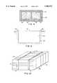
- FIG. 6is a perspective view of a core for a composite structure according to a second embodiment of the present invention.
- FIG. 7is a schematic cross-sectional view of a composite structure being formed according to the second embodiment of the present invention.
- FIG. 8is a schematic cross-sectional view of a composite structure being formed using an integrated mold and vacuum structure
- FIG. 9is a schematic cross-sectional view of a rigid mold and flexible lid for forming a composite structure
- FIG. 10is a perspective view of a core for a composite structure having multiple main feeder grooves
- FIG. 11is a schematic cross-sectional view of an integrated mold and vacuum bag for forming a composite structure according to a further embodiment of the present invention.
- FIG. 12is a perspective view of one side of a textured sheet of material forming the integrated mold and vacuum bag of FIG. 11;
- FIG. 13is a perspective view of the other side of the textured sheet of FIG. 12;
- FIG. 14is a schematic, partial cross-sectional view of a composite structure and mold assembly according to a further embodiment of the invention.
- FIG. 15is a perspective view of a closed cell used in the composite structure of FIG. 14;
- FIGS. 16A, 16B, 16C, and 16Dillustrate a variety of arrangements of the cores used in the composite structure of FIG. 14;
- FIGS. 17A, 17B, 17C, and 17Dillustrate a variety of fiber wrapping configurations
- FIG. 18is a schematic, partial cross-sectional view of a composite structure and mold assembly according to a still further embodiment of the invention.
- FIG. 19is a partial cross-sectional view along line A--A of FIG. 18;
- FIG. 20is a schematic, partial cross-sectional view of a further configuration of a composite structure and mold assembly according to the present invention.
- FIG. 21is a schematic, partial cross-sectional view of a still further configuration of a composite structure and mold assembly according to the present invention.
- a large composite part made according to the present inventionincludes a core 12, shown in FIG. 1.
- the coreis made from a material able to support the pressure of a vacuum. Typical materials include foams, such as a polyurethane or a polyvinyl chloride, or balsa wood.
- the corecan be solid or hollow, such as a blown polyethylene. Concrete may also be used.
- the coreis shown as a rectangular block, although other configurations are possible, as discussed further below.
- One or more main feeder grooves or channels 14are provided in the surface 16 of the core.
- the main feeder groovemay circumscribe the entire core to form a loop.
- a resin distribution networkcomprising channels of a smaller cross-sectional area than the main feeder groove is provided in contact with the surface of the core for fluid communication with the main feeder groove.
- the resin distribution networkis provided in the form of a plurality of microgrooves 18 machined in the surface 16 of the core 12, as shown in FIG. 1.
- the microgrooves 18are generally arranged transversely to the main feeder groove 14. Some of the microgrooves may circumscribe the entire core to create a resin flow loop beginning and ending at the main feeder groove.
- the actual relation of the microgrooves to the main feeder groovedepends on the geometry of the core and the optimization of the resin impregnation, as discussed further below.
- the core 14 with the network of groovesis covered with one or more layers of a fiber material 20, illustrated schematically in FIG. 2.
- the fiber materialmay be a cloth or mat formed from fibers of glass, carbon, or other suitable material.
- the coremay be completely surrounded with fiber material, or one or more surfaces of the core may be left free of fiber material.
- the fiber materialmay be wrapped in a sheet around the core, or individual pieces of fiber material may be applied to the desired core faces.
- the fibermay also be supplied in a tubular form into which the core is inserted.
- a plurality of fiber wrapped coresare arranged to form the desired finished part. Although two cores are shown in FIG. 2, the actual number and arrangement of cores is determined by the desired finished part.
- One or more layers of a fiber materialcan be wrapped around a plurality of cores to form an outer skin 22, shown schematically in FIG. 2. The particular number of layers of fiber material, the type, and the arrangement depend on the desired finished part and can be readily determined by those of skill in the art.
- a bleeder layeris generally provided in the form of a tab 23 extending from an outer fiber layer to a vacuum outlet 25. Peel plies, typically required with prior art vacuum processes, are generally not needed with the process of the present invention.
- the fiber material 24 surrounding and between the corescreates structural members such as shear ties, compression webs, and beams.
- structural memberssuch as shear ties, compression webs, and beams.
- a plurality of triangular cores 40are used to form a deck.
- the fiber material between adjacent triangular coresforms diagonal structural members 41 that support both compression and shear forces.
- suitable fittings 26such as plastic or copper tees, are positioned in the main feeder grooves 14 to facilitate the subsequent insertion of resin supply tubes 28.
- One or more fittingsmay be positioned in each feeder groove, to accommodate the desired resin flow.
- the lay-upis placed against a mold 29, and a vacuum bag 30 is then placed over the lay-up, including the plastic fittings, and sealed to the mold in a manner known in the art, as shown schematically in FIG. 2.
- the vacuum bagis then punctured and the supply tubes 28 are inserted through the vacuum bag directly into their respective fittings 26.
- the supply tubesare sealed to the bag to retain vacuum integrity.
- the main feeder groovesare supplied directly with resin by penetrating the outer vacuum bag with a supply tube that is inserted directly into the groove.
- the vacuum bag and moldmay also be integrated into a single structure 80 which is rigid enough to retain its shape as a mold but flexible enough to collapse against the part upon application of a vacuum.
- the integrated structure 80may comprise a thin gauge steel sheet, such as 0.25 inch or thinner.
- the cores 82 and fiber material 84, 86, as described above,are encapsulated in the steel sheet. Holes are drilled through the sheet to access the fittings. Resin impregnation occurs as described above.
- the integrated structuremay be formed of other suitable materials, such as rubber or silicone or a thin composite sheet material such as a plastic laminated metal.
- FIG. 9illustrates a further mold embodiment in which a rigid mold 90 is sealed with a flexible lid 92 formed, for example, from a steel or plastic material.
- a partcomprising the cores and fiber material as described above, is placed in the recess 94 defined by the rigid mold.
- a vacuum groove 96 in the lidsurrounds the part. Holes are provided through the lid or mold to access fittings for resin impregnation as described above. During impregnation of the resin under vacuum, the lid flexes at the edge of the vacuum groove, to allow compaction of the part.
- the resinsuch as a polyester, vinyl ester, epoxy, phenolic, acrylic, or bismaleimide, travels relatively quickly through the main feeder grooves 14 and into the microgrooves 18. From the microgrooves, the resin penetrates the fiber material 20, 22. Impregnation results from resin infusion originating at the core surface 16 and migrating outwardly to the exterior of the part.
- the fiber material on adjacent core surfacesmay be impregnated via a main feeder groove in one of the adjacent cores, as indicated in FIGS. 3 and 4.
- the cross-sectional area of the main feeder groove and the cross-sectional area and spacing of the microgroovesare optimized to provide a suitable time to allow the resin to impregnate all of the fiber material before curing without leaving unimpregnated areas.
- a typical main feeder groovemay have a depth of 0.5 inch and a width of 0.5 inch for a cross-sectional area of 0.25 square inches.
- Typical microgroovesmay have a depth of 0.125 inch and a width of 0.125 inch for a cross-sectional area of approximately 0.016 square inches.
- the microgroovesmay be spaced 1.0 inch on center. These dimensions may be modified to accommodate reinforcement fiber materials of different types and/or thicknesses.
- the cross-sectional area of the main feeder groovesmay be increased if the part is particularly large to more rapidly distribute the resin to all sections of the part.
- multiple main feeder grooves 14may be provided in a core 12, as indicated in FIG. 10.
- the cross-sectional area of the main feeder grooves or the microgroovesmay be reduced to create flow restrictions to increase resin dwell time at a particular area.
- Resin dwell timemay also be increased by placing a resin "fuse" in the feeder groove which temporarily blocks the resin flow.
- the fusedissolves after contact with the resin after a known period of time, which may be set by the length of the fuse. For example, with a vinyl ester resin, a styrofoam fuse has been used successfully.
- the feeder groovesmay also terminate to redirect resin flow.
- the main feeder grooves 14allow passage of resin from one core to an adjacent core. Holes may be provided through the cores to connect main feeder grooves. Each main feeder groove may be supplied with resin simultaneously, creating parallel circuits, or in a prescribed sequence, creating series circuits, depending on the geometry and size of the part to be impregnated. Additionally, the main feeder grooves may be independent of each other, creating separate circuits.
- the resinAfter impregnation, the resin is allowed sufficient time to cure. Once cured, the microgrooves 18 are filled with solid resin. This resin provides a lateral locking mechanism which improves the interlaminar shear strength of the bond between the fiber reinforced composite and the core. The resin remaining in the groove network also increases the forces necessary to delaminate the fiber reinforced face skins from the core.
- triangular cores 40are shown in FIG. 3.
- the triangular coresmay have main feeder grooves 42 provided in at least two surfaces.
- a central triangular core 44may have main feeder grooves in three surfaces.
- Microgroovesare provided in the surfaces as described above.
- a plurality of triangular coresmay be arranged in, for example, a row to form a deck.
- resin, supplied through tubes 46is impregnated sequentially beginning at the central core and progressing toward the edges, as shown by the shaded region 48 in FIG. 4.
- the arcuate core 50may have a main feeder groove 52 in one surface and a network of microgrooves 54 radiating from the feeder groove to circumscribe the core.
- the arcuate coresmay be used to form curved structures such as boat hulls or arches.
- a core 60is provided with a main feeder groove 62 as described above.
- a distribution medium 64is then provided adjacent the core faces.
- the mediumcomprises a network of open passageways formed by a structure capable of maintaining the passageways in an open condition during application of the vacuum.
- the mediummay comprise intersecting filaments held in spaced relation from the core surface by post-like members located at each filament intersection, a grid-like structure of aligned strips, or an open weave fabric.
- Suitable distribution mediaare known for example, from U.S. Pat. Nos. 4,902,215 and 5,052,906, incorporated herein by reference.
- a fiber material 66is then wrapped over the distribution media, as described above.
- a plurality of coresare arranged to form the desired finished part, and a vacuum bag 68 is placed over the cores and fiber material, as described above.
- Resin supply tubes 70 leading from a resin sourceare inserted through the bag 68 and fiber material 66 to fittings 72 in the main feeder grooves 62.
- the supply tubes 70are sealed to the vacuum bag in a manner known in the art.
- Resinis fed through the supply tubes to the main feeder grooves.
- the resintravels relatively quickly through the main feeder grooves and into the distribution media. From the distribution media, the resin penetrates the fiber material. A suitable time interval is provided to allow the resin to cure.
- Resin distribution mediapresents a more uniform resin flow front than the microgrooves. For this reason, resin distribution media are generally preferred for more complicated parts, whereas microgrooves are preferred to conserve resin, since less resin flows through the microgrooves.
- the vacuum bag and moldare integrated into a single tool 102 formed from a textured sheet 104 of metal, such as a thin gauge steel sheet.
- the sheetis rigid enough to retain its shape as a mold, but flexible enough to collapse or be pulled against the part under the vacuum applied during a resin impregnation process, discussed further below.
- a sheet thickness of 0.25 inch or lesshas been found suitable.
- a plastic or a composite materialsuch as a metal and plastic laminate formed as a textured sheet may also be used.
- the textureis formed by closely spaced upraised portions 108 formed on one side of the sheet 104 which correspond to depressions 106 on the other side of the sheet.
- the closely spaced upraised portions 108define valleys 110 therebetween which form a resin distribution network.
- the upraised portionsmay have a generally hexagonal shape having a longest dimension of between 3/8 inch and 7/16 inch. A depth of the valleys of approximately 30 thousandths of an inch has been found to be suitable.
- Such a textured sheetis readily formable and is commercially available from Ardmore Textured Metal of Edison, N.J.
- the texturecould be provided on a single side of the sheet if desired, such that the upraised portions do not make corresponding depressions on the other side.
- the sheetis shaped into the desired form of a mold 112 having a mold cavity 118 with the upraised portions of the sheet forming the interior walls of the cavity, thereby facing the part to be impregnated.
- Main feeder grooves 114are formed directly in the sheet 104 in the desired locations, rather than in the cores as described above. The main feeder grooves may have dimensions as discussed above.
- Vacuum outlet channels 116are formed around the perimeter of the tool.
- a fiber lay upis placed within the cavity 118 adjacent the textured surfaces of the tool, and the tool is sealed as with a tacky tape or other seal as is known in the art.
- a peel plymay be used if the texture is not to be retained on the part.
- a peel plymay be omitted if the texture is desired to be retained on the surface of the part.
- Forming the texture on the partimparts some further stiffness to the part and may be desired for aesthetic reasons as well.
- the fiber lay upmay comprise cores wrapped with fiber material as discussed above. Fittings are inserted into the main feeder grooves through punctures made in the sheet as discussed above.
- a vacuumis applied to the interior of the tool, and the sheet of textured material is pulled adjacent the fiber lay up such that the tops of the upraised portion contact the fiber lay up, but the valleys remain open to form a network of narrow, interconnected passageways through which resin is able to flow.
- resinis drawn first into the main feeder grooves and then into the valleys. From the valleys, the resin is able to fully impregnate the fiber material, flowing finally to the vacuum outlet channels around the perimeter. The resin is allowed sufficient time to cure. After curing, the part is removed from the tool.
- the textured sheetcan be used as a lid in conjunction with a conventional mold.
- the fiber lay upis placed against the mold surface.
- the textured sheetis placed over the fiber lay up and sealed to the mold in any suitable manner. Additional resin distribution media may need to be used adjacent the conventional mold surfaces. Resin impregnation occurs as discussed above.
- the textured sheetcan also be used as a master mold which is used to make tools from other materials, such as ceramics.
- the toolis then used as a mold in the resin impregnation process.
- the sheetcomprises a negative of the tool; that is, the side of the sheet having the indentations is used to form the tool.
- the resulting toolhas the configuration of the upraised portions separated by the valleys, which form a resin distribution medium as discussed above.
- a ceramic moldgenerally does not flex to collapse against the part under vacuum. In this case, a separate vacuum bag is used in conjunction with the mold, as is known in the art.
- FIGS. 14 through 21illustrate further embodiments of the invention, which are particularly suitable for forming sandwich-type structures such as hollow-core or foam core panels.
- the structureis formed by a plurality of cores 132, which may be hollow cells (FIG. 14) or foam blocks (FIG. 21), arrayed according to the desired finished part to be formed.
- One or more layers of fiber material 134covers the top surfaces 136 and bottom surfaces 138 of the arrayed cores to form face skins of the structure.
- Fiber materialmay also be located within the regions 140 between each core 132 and/or the cores may be wrapped with a fiber material 135 partially or fully about the sides of the cores. In this manner, each core may be covered partially or fully with a fiber material.
- the fiber materialmay be a cloth or mat formed from fibers of glass, carbon, KEVLAR, or other suitable material.
- the fiber materialmay be wrapped in a sheet around the core, or individual pieces of fiber material may be applied to the desired core faces.
- the fibermay also be supplied in a tubular form into which the core is inserted. As indicated in FIGS. 17A through 17D, the fiber may surround the sides of the cores and terminate at the top and bottom, may terminate some distance above and/or below the core, may wrap slightly onto the top and/or bottom of each core, or may wrap completely onto the top and bottom of each core.
- the fiber material surrounding and between the corescreates structural members such as shear ties, compression webs, and beams.
- the fiber materialcan be supplied as a multiaxial braid, i.e., having fibers running in multiple directions to carry stresses running in different directions, such as biaxial, triaxial, or quadra-axial braid.
- the orientation of the braid fiberscan be chosen to suit the structural requirements of the finished part.
- FIG. 15illustrates a hollow core 132 comprising a closed container or cell having one or more grooves 142 integrally formed in the sides.
- each hollow coreis formed from a plastic material, such as a polyethylene, polypropylene, polyvinyl chloride (PVC), or nylon.
- the corescan be formed by a blow molding process, as would be known in the art. Other processes, such as injection molding, twin sheet vacuum forming, or roto molding, can also be used.
- the groovesare typically V-shaped in cross-section, since the V shape aids in removing the cells from the mold. However, other shapes, such as a U shape, can be used.
- the grooves 142are sized, as discussed above, to facilitate resin flow therealong.
- the groovesfunction as microgrooves.
- Main feeder groovesare generally not necessary in the surfaces of the cores, although one or more feeder grooves could be provided if desired, particularly if the core were large.
- the groovescan be formed in any suitable configuration, such as the diagonal configuration shown in FIG. 15. The diagonal configuration provides for easy release from the blow molding apparatus.
- the groovescircumscribe the core to facilitate resin transport to all sides of the cores.
- the corners of the coresare also preferably rounded or chamfered, which further facilitates resin flow around the sides of the cores.
- the corescan have any suitable shape, such as rectangular boxes (shown in FIG. 15), cylinders, or elongated triangles or hexagons, and may be arranged in any suitable pattern, as shown in FIGS. 16A through 16D.
- the cores 132which may be wrapped with the fiber material 135, are arranged against the rigid surface 144 of a mold assembly.
- FIG. 14illustrates an embodiment in which the cores are wrapped on all sides with a fiber material.
- FIGS. 18 and 19illustrate an embodiment in which the cores 132 are not wrapped with a fiber material or provided with grooves, and the resin flows from the upper to the lower surface via rounded corners 133 on the cores.
- the mold assemblyincludes a flexible portion which is generally a vacuum bag 146 placed over the structure and affixed to the mold surface with a seal 149 about the periphery.
- the vacuum bagincludes one or more main feeder channels 148, which may be formed integrally with the bag (FIG. 14) or separately therefrom (FIG. 21).
- a resin distribution network of small, intersecting channels 150may be provided for fluid communication with the main feeder channel(s) 148.
- the smaller channelscan be formed integrally with the vacuum bag (illustrated in FIG. 20), as described in U.S. Pat. Nos. 5,439,635 and 5,316,462, incorporated herein by reference.
- the smaller channelscan also be provided by a separate distribution medium (illustrated in FIG. 21), as described above and in U.S. Pat. Nos. 5,0952,906 and 4,902,215.
- a peel ply 151(illustrated in FIG. 21) may be used if desired.
- a vacuum channel 152 or bleeder 153, connected to a vacuum source (not shown),is also provided about the periphery of the structure.
- a resin supply(not shown) is connected directly into the main feeder channel(s) 148 in the vacuum bag 146.
- a vacuumis drawn via the vacuum channel 152, which evacuates air from the pores in the fiber material.
- the resin supplyis opened, and resin is drawn by the vacuum relatively quickly into the main feeder channel(s) 148 and through the smaller channels 150 of the vacuum bag or separate distribution medium.
- the resinpenetrates the fiber material 134 covering the upper surface 136 of the cores 132 and reaches the surface of the cores.
- the resinagain travels relatively quickly along the grooves 142 of the cores 132, thereby penetrating the fiber material 135 in the regions 140 between adjacent cores and between the cores and the mold 144.
- a resin with a low viscositycan be used, which also aids in rapid travel along the microgrooves and penetration of the fiber material.
- the coresare hollow cells formed at atmospheric pressure, they push outwardly against each other and the fiber material while under vacuum. This minimizes the pore spaces in the fiber material and ensures that a minimum amount of resin is used.
- the resulting composite structureis quite strong.
- Various deck configurations with 4 and 5 foot spans and approximately 8 inch depthswere loaded until failure; the decks failed at loads ranging from 31 to 92 kips.
- the webs, in the regions 140 between the coresare structurally continuous. That is, webs extending in one direction do not physically cross through webs extending in another direction. Their stresses, however, act as if the webs were continuous in both directions. This enables shear loads to be transferred to adjacent webs.
- a panel formed in this mannercan be thinner than, for example, a structurally equivalent steel structure, since steel I beams extending in a first direction cannot in practice cross through I beams extending in another direction.
- the coresremain in the structure and can contribute to the structure's strength. Additionally, the resin in the microgrooves remains after curing, increasing interlaminar shear strength and delamination strength, and provides additional resistance to buckling.
- the cores of the present inventioncan be arranged more than one core deep, if desired.
- fiber materialis placed between layers of cores.
- This configurationis advantageous to provide, for example, fire hardening or earthquake resistance. For fire hardening, if one layer burns off, another layer may still be left in place. For earthquake resistance, additional strength can be provided by multiple layers of cores.
Landscapes
- Engineering & Computer Science (AREA)
- Mechanical Engineering (AREA)
- Chemical & Material Sciences (AREA)
- Composite Materials (AREA)
- Casting Or Compression Moulding Of Plastics Or The Like (AREA)
- Moulding By Coating Moulds (AREA)
- Moulds For Moulding Plastics Or The Like (AREA)
- Golf Clubs (AREA)
- Laminated Bodies (AREA)
- Blow-Moulding Or Thermoforming Of Plastics Or The Like (AREA)
- Processing And Handling Of Plastics And Other Materials For Molding In General (AREA)
Abstract
Description
Claims (15)
Priority Applications (16)
| Application Number | Priority Date | Filing Date | Title |
|---|---|---|---|
| US08/900,687US5904972A (en) | 1995-06-07 | 1997-07-25 | Large composite core structures formed by vacuum assisted resin transfer molding |
| CN98811073ACN1278762A (en) | 1997-07-25 | 1998-07-23 | Large Composite Core Structure Formed by Vacuum Assisted Resin Transfer Molding |
| AT98936997TATE253448T1 (en) | 1997-07-25 | 1998-07-23 | LARGE COMPOSITE CORE STRUCTURES MADE BY VACUUM-ASSISTED RESIN TRANSFER SPRAYING AND METHODS |
| NZ502432ANZ502432A (en) | 1997-07-25 | 1998-07-23 | Large composite core structures formed by vacuum assisted resin transfer molding |
| KR1020007000835AKR20010022262A (en) | 1997-07-25 | 1998-07-23 | Large composite core structures formed by vacuum assisted resin transfer molding |
| DE69819509TDE69819509T2 (en) | 1997-07-25 | 1998-07-23 | LARGE COMPOSITE STRUCTURES THAT ARE MADE BY RESIN WITH VACUUM-AIDED TRANSFER SPRAYING AND METHOD |
| DK98936997TDK0998385T3 (en) | 1997-07-25 | 1998-07-23 | Large composite core structures formed by vacuum-assisted resin transfer molding and fabrication method thereof |
| ES98936997TES2210787T3 (en) | 1997-07-25 | 1998-07-23 | LARGE COMPOSITE NUCLEUS STRUCTURES FORMED BY A MOLDING PROCEDURE BY RESOURCE TRANSFER UNDER EMPTY AND MANUFACTURING METHOD. |
| JP2000503992AJP2001510748A (en) | 1997-07-25 | 1998-07-23 | Large composite structure with core by resin transfer molding method using vacuum |
| CA002297793ACA2297793A1 (en) | 1997-07-25 | 1998-07-23 | Large composite core structures formed by vacuum assisted resin transfer molding |
| AU85810/98AAU741696B2 (en) | 1997-07-25 | 1998-07-23 | Large composite core structures formed by vacuum assisted resin transfer molding |
| PCT/US1998/015209WO1999004964A1 (en) | 1997-07-25 | 1998-07-23 | Large composite core structures formed by vacuum assisted resin transfer molding |
| PT98936997TPT998385E (en) | 1997-07-25 | 1998-07-23 | COMPOSITE STRUCTURES OF LARGE DIMENSIONS WITH NUCLEALS FORMED BY A PROCESS OF MOLDING BY TRANSFER OF RESIN UNDER VACUUM ACTION AND THEIR MANUFACTURING METHOD |
| EP98936997AEP0998385B1 (en) | 1997-07-25 | 1998-07-23 | Large composite core structures formed by vacuum assisted resin transfer molding and method of fabrication |
| US09/282,989US6159414A (en) | 1995-06-07 | 1999-03-31 | Large composite core structures formed by vacuum assisted resin transfer molding |
| NO20000341ANO20000341L (en) | 1997-07-25 | 2000-01-24 | Large composite core structures formed by vacuum-assisted resin transpress molding |
Applications Claiming Priority (3)
| Application Number | Priority Date | Filing Date | Title |
|---|---|---|---|
| US08/475,849US5958325A (en) | 1995-06-07 | 1995-06-07 | Large composite structures and a method for production of large composite structures incorporating a resin distribution network |
| US08/612,251US6773655B1 (en) | 1995-06-07 | 1996-03-07 | Large composite structures and a method for production of large composite structures incorporating a resin distribution network |
| US08/900,687US5904972A (en) | 1995-06-07 | 1997-07-25 | Large composite core structures formed by vacuum assisted resin transfer molding |
Related Parent Applications (1)
| Application Number | Title | Priority Date | Filing Date |
|---|---|---|---|
| US08/612,251Continuation-In-PartUS6773655B1 (en) | 1995-06-07 | 1996-03-07 | Large composite structures and a method for production of large composite structures incorporating a resin distribution network |
Related Child Applications (1)
| Application Number | Title | Priority Date | Filing Date |
|---|---|---|---|
| US09/282,989DivisionUS6159414A (en) | 1995-06-07 | 1999-03-31 | Large composite core structures formed by vacuum assisted resin transfer molding |
Publications (1)
| Publication Number | Publication Date |
|---|---|
| US5904972Atrue US5904972A (en) | 1999-05-18 |
Family
ID=25412941
Family Applications (2)
| Application Number | Title | Priority Date | Filing Date |
|---|---|---|---|
| US08/900,687Expired - Fee RelatedUS5904972A (en) | 1995-06-07 | 1997-07-25 | Large composite core structures formed by vacuum assisted resin transfer molding |
| US09/282,989Expired - Fee RelatedUS6159414A (en) | 1995-06-07 | 1999-03-31 | Large composite core structures formed by vacuum assisted resin transfer molding |
Family Applications After (1)
| Application Number | Title | Priority Date | Filing Date |
|---|---|---|---|
| US09/282,989Expired - Fee RelatedUS6159414A (en) | 1995-06-07 | 1999-03-31 | Large composite core structures formed by vacuum assisted resin transfer molding |
Country Status (15)
| Country | Link |
|---|---|
| US (2) | US5904972A (en) |
| EP (1) | EP0998385B1 (en) |
| JP (1) | JP2001510748A (en) |
| KR (1) | KR20010022262A (en) |
| CN (1) | CN1278762A (en) |
| AT (1) | ATE253448T1 (en) |
| AU (1) | AU741696B2 (en) |
| CA (1) | CA2297793A1 (en) |
| DE (1) | DE69819509T2 (en) |
| DK (1) | DK0998385T3 (en) |
| ES (1) | ES2210787T3 (en) |
| NO (1) | NO20000341L (en) |
| NZ (1) | NZ502432A (en) |
| PT (1) | PT998385E (en) |
| WO (1) | WO1999004964A1 (en) |
Cited By (97)
| Publication number | Priority date | Publication date | Assignee | Title |
|---|---|---|---|---|
| US6117519A (en)* | 1997-03-19 | 2000-09-12 | Burns; Mark L. | Composite core material, composite material and method of assembly |
| US20020022422A1 (en)* | 1999-12-07 | 2002-02-21 | Waldrop John C. | Double bag vacuum infusion process and system for low cost, advanced composite fabrication |
| WO2002020256A1 (en)* | 2000-09-08 | 2002-03-14 | Lockheed Martin Corporation | Unitized fastenerless composite structure |
| US6367406B1 (en) | 1999-09-24 | 2002-04-09 | Larson/Glastron Boats, Inc. | Boat and method for manufacturing using resin transfer molding |
| US20030077965A1 (en)* | 2001-07-23 | 2003-04-24 | Mack Patrick E. | Three-dimensional spacer fabric resin infusion media and reinforcing composite lamina |
| US20030102604A1 (en)* | 2001-07-23 | 2003-06-05 | Mack Patrick E. | Three-dimensional spacer fabric resin interlaminar infusion media process and vacuum-induced reinforcing composite laminate structures |
| US20040001946A1 (en)* | 2002-06-27 | 2004-01-01 | Wenguang Ma | Polyester core materials and structural sandwich composites thereof |
| JP2004009604A (en)* | 2002-06-07 | 2004-01-15 | Mitsubishi Heavy Ind Ltd | Apparatus and method for manufacturing fiber reinforced resin structure |
| US6740381B2 (en) | 1999-12-28 | 2004-05-25 | Webcore Technologies, Inc. | Fiber reinforced composite cores and panels |
| US6739861B2 (en) | 2001-11-26 | 2004-05-25 | Sikorsky Aircraft Corporation | High pressure co-cure of lightweight core composite article utilizing a core having a plurality of protruding pins |
| US20040154473A1 (en)* | 1999-07-08 | 2004-08-12 | Saint-Gobain Performance Plastics Corporation | Belts with integral flights for use in high-temperature food processing equipment and systems including such belts |
| US20040157519A1 (en)* | 2002-12-30 | 2004-08-12 | University Of Maine | Composites pressure resin infusion system (ComPRIS) |
| US20040204570A1 (en)* | 1999-03-13 | 2004-10-14 | Basf Akiengesellschaft | Azoxy dyes and copper complexes thereof |
| US20050031720A1 (en)* | 2002-01-31 | 2005-02-10 | Eads Deutschland Gmbh | Method and devices for producing fiber-reinforced components |
| US20050040553A1 (en)* | 2003-08-14 | 2005-02-24 | Lockheed Martin Corporation | Apparatus and methods for distributing a substance |
| US6860082B1 (en)* | 1999-04-12 | 2005-03-01 | Isuzu Motors Limited | Heat insulating wall member, and method of manufacturing the same |
| US20050074593A1 (en)* | 2000-12-27 | 2005-04-07 | Webcore Technologies, Inc. | Fiber reinforced composite cores and panels |
| WO2005035217A1 (en)* | 2003-09-16 | 2005-04-21 | Alcan Baltek Corporation | Polyester core materials and structural sandwich composites thereof |
| US20050097984A1 (en)* | 2003-11-07 | 2005-05-12 | Davis Geoffrey C.R. | Composite transmission housing with discontinuous fiber preforms |
| US7029267B2 (en) | 2003-10-23 | 2006-04-18 | Saint- Gobain Technical Fabrics Canada, Ltd | Reusable vacuum bag and methods of its use |
| US7160498B2 (en) | 2004-03-08 | 2007-01-09 | Tracker Marine, L.L.C. | Closed molding tool |
| US20070017626A1 (en)* | 2005-07-19 | 2007-01-25 | Pearson Everett A | Composite structure and method of manufacture |
| US20070090554A1 (en)* | 2005-10-26 | 2007-04-26 | Rick Wykoff | Panel molding method and apparatus |
| WO2007056840A1 (en) | 2005-11-21 | 2007-05-24 | Faroex Ltd. | Composite body for a vehicle |
| US20070256599A1 (en)* | 2005-12-16 | 2007-11-08 | Jack Rigsby | Inorganic Composite Material And Manufacturing Process |
| US20070261329A1 (en)* | 2005-12-16 | 2007-11-15 | Jack Rigsby | Inorganic Composite Building Panel |
| US20080008836A1 (en)* | 2006-05-01 | 2008-01-10 | Kipp Michael D | Method for extending the useful life of mold type tooling |
| US20080044630A1 (en)* | 2005-11-21 | 2008-02-21 | Kevin Lusk | Structural shear plate for a vehicle |
| US20080105997A1 (en)* | 2006-10-17 | 2008-05-08 | Ridges Michael D | Method for enhancing the sealing potential of formable, disposable tooling materials |
| US20080106007A1 (en)* | 2006-10-17 | 2008-05-08 | Kipp Michael D | Resin infusion process utilizing a reusable vacuum bag |
| US20080131716A1 (en)* | 2006-12-04 | 2008-06-05 | American Consulting Technology & Research, Inc. | Shrinkable film barrier for mandrel tooling members |
| EP1942039A1 (en) | 2006-09-01 | 2008-07-09 | Faroex Ltd. | Structural shear plate for a vehicle |
| WO2008086022A1 (en)* | 2007-01-09 | 2008-07-17 | American Consulting Technology & Research Inc. | Multi-function vacuum bag for composite part manuacture |
| US20080185754A1 (en)* | 2007-01-19 | 2008-08-07 | John Wirt | Method and apparatus for molding composite articles |
| US20080233357A1 (en)* | 2005-09-27 | 2008-09-25 | Winckler Steven J | Sandwich Structures and Methods of Making Same |
| US20090041972A1 (en)* | 2007-08-07 | 2009-02-12 | Rodman William L | Composite structures and methods of making same |
| US20090145545A1 (en)* | 2007-12-07 | 2009-06-11 | The Boeing Company | Composite Manufacturing Method |
| US20090148647A1 (en)* | 2007-12-07 | 2009-06-11 | The Boeing Company | Method of Fabricating Structures Using Composite Modules and Structures Made Thereby |
| US20090155521A1 (en)* | 2007-08-07 | 2009-06-18 | Rodman William L | Composite structures and methods of making same |
| US20090208683A1 (en)* | 2007-12-06 | 2009-08-20 | Rodman William L | Alignment system and methods for composite assemblies |
| US20090230729A1 (en)* | 2008-03-13 | 2009-09-17 | Kevin Lusk | Floor panel for a vehicle |
| US20100012260A1 (en)* | 2007-05-22 | 2010-01-21 | Brennan Joseph D | Pre-patterned layup kit and method of manufacture |
| US20100078126A1 (en)* | 2008-09-30 | 2010-04-01 | The Boeing Company | Compaction of Prepreg Plies on Composite Laminate Structures |
| US20100080941A1 (en)* | 2008-10-01 | 2010-04-01 | The Boeing Company | Composite truss panel having fluted core and method for making the same |
| US20100080942A1 (en)* | 2008-10-01 | 2010-04-01 | The Boeing Company | Joining curved composite sandwich panels |
| US20100135817A1 (en)* | 2008-10-22 | 2010-06-03 | Wirt John C | Wind turbine blade and method for manufacturing thereof |
| US20100140975A1 (en)* | 2008-01-31 | 2010-06-10 | Hankuk Fiber Glass Co., Ltd. | Integrated Composite-Material Vehicle Body for a Transportation Vehicle, and a Production Method Therefor |
| US20100186893A1 (en)* | 2009-01-29 | 2010-07-29 | Lockheed Martin Corporation | System, method and apparatus for fabricating composite structures |
| US20100192659A1 (en)* | 2009-02-05 | 2010-08-05 | Paul Edward Krajewski | Elevated temperature forming method and preheater apparatus |
| US20110072960A1 (en)* | 2007-11-16 | 2011-03-31 | Composite Technologies | Armor shielding |
| US20110081514A1 (en)* | 2009-10-01 | 2011-04-07 | Webcore Ip, Inc. | Composite cores and panels |
| US20110079174A1 (en)* | 2006-12-22 | 2011-04-07 | The Boeing Company | Leak Detection in Vacuum Bags |
| US20110100541A1 (en)* | 2009-11-04 | 2011-05-05 | Mitsubishi Heavy Industries, Ltd. | Apparatus and method for manufacturing fiber reinforced plastic structure |
| EP2319683A1 (en) | 2009-11-04 | 2011-05-11 | Mitsubishi Heavy Industries, Ltd. | Apparatus and method for manufacturing fiber reinforced plastic structure |
| US7959058B1 (en) | 2005-01-13 | 2011-06-14 | The United States Of America As Represented By The Secretary Of The Navy | Hybrid composite welded joint |
| US7972698B2 (en) | 2004-10-21 | 2011-07-05 | Graftech International Holdings Inc. | Carbon foam core panels |
| US20110183104A1 (en)* | 2008-09-03 | 2011-07-28 | Juergens Manuela Richter | Sandwich panel with integrated reinforcing structure and method for the production thereof |
| US20110229686A1 (en)* | 2010-03-17 | 2011-09-22 | Dueker Douglas K | Reinforced Boards and Other Building Materials |
| US8230713B2 (en) | 2008-12-30 | 2012-07-31 | Usamp | Elevated temperature forming die apparatus |
| US8313600B2 (en) | 2008-08-15 | 2012-11-20 | Sigma-Tek, Llc | Method and system for forming composite geometric support structures |
| US20130039775A1 (en)* | 2010-02-18 | 2013-02-14 | Wobben Properties Gmbh | Method for producing wind power plant rotor blades and a wind power plant rotor blade |
| US8389104B2 (en) | 2009-10-02 | 2013-03-05 | Milliken & Company | Composite cores and panels |
| US8419883B2 (en) | 2000-12-27 | 2013-04-16 | Milliken & Company | Fiber reinforced composite cores and panels |
| US8551380B2 (en) | 2010-11-12 | 2013-10-08 | The Boeing Company | Method of laying up prepreg plies on contoured tools using a deformable carrier film |
| US8663791B2 (en) | 2011-04-04 | 2014-03-04 | Milliken & Company | Composite reinforced cores and panels |
| US8707766B2 (en) | 2010-04-21 | 2014-04-29 | The Boeing Company | Leak detection in vacuum bags |
| US8834667B2 (en) | 2010-10-19 | 2014-09-16 | The Boeing Company | Method for joining sandwich truss core panels and composite structures produced therefrom |
| GB2515025A (en)* | 2013-06-11 | 2014-12-17 | Aviat Entpr Ltd | Spar |
| US8936695B2 (en) | 2007-07-28 | 2015-01-20 | The Boeing Company | Method for forming and applying composite layups having complex geometries |
| US8980435B2 (en) | 2011-10-04 | 2015-03-17 | General Electric Company | CMC component, power generation system and method of forming a CMC component |
| US20150217521A1 (en)* | 2008-07-18 | 2015-08-06 | Fibercore Ip B.V. | Method for producing sandwich panel |
| US20150328845A1 (en)* | 2014-05-19 | 2015-11-19 | The Boeing Company | Manufacture of a resin infused one-piece composite truss structure |
| US9194238B2 (en) | 2012-11-28 | 2015-11-24 | General Electric Company | System for damping vibrations in a turbine |
| CN105415706A (en)* | 2015-11-03 | 2016-03-23 | 千人计划新材料镇江研究院有限公司 | Vacuum infusion one-time forming method for composite sandwich structure |
| US9387657B2 (en) | 2010-11-12 | 2016-07-12 | The Boeing Company | Method of fabricating a curved composite structure using composite prepreg tape |
| WO2016203160A1 (en) | 2015-06-16 | 2016-12-22 | Conseil Et Technique | Composite material part |
| US20170015071A1 (en)* | 2013-01-29 | 2017-01-19 | Thyssenkrupp Presta Ag | Steering column produced from fibre-composite and on the basis of pultrusion, braiding and/or winding technology |
| US9597821B2 (en) | 2012-09-27 | 2017-03-21 | General Electric Company | Frame assembly, mold, and method for forming rotor blade |
| US9701067B2 (en) | 2010-11-12 | 2017-07-11 | The Boeing Company | Method of laying up prepreg plies on contoured tools using a deformable carrier film |
| US9771714B2 (en)* | 2010-06-17 | 2017-09-26 | Jerry Castelle | Vacuum insulation panel |
| US9770871B2 (en) | 2007-05-22 | 2017-09-26 | The Boeing Company | Method and apparatus for layup placement |
| RU2669499C1 (en)* | 2016-11-29 | 2018-10-11 | ООО "Композитные технологии" | Method of manufacturing products of three-layer integral-type structure from polymer composite materials |
| EP2562413B1 (en) | 2005-02-03 | 2018-10-24 | Vestas Wind Systems A/S | Method of manufacturing a wind turbine blade shell member |
| US20180356038A1 (en)* | 2015-11-25 | 2018-12-13 | United Technologies Corporation | Composite pressure vessel assembly and method of manufacturing |
| US20190010918A1 (en)* | 2017-07-05 | 2019-01-10 | General Electric Company | Enhanced through-thickness resin infusion for a wind turbine composite laminate |
| US10450141B2 (en) | 2016-11-29 | 2019-10-22 | Saint-Gobain Performance Plastics Corporation | Composite belt profile |
| USD887926S1 (en) | 2017-01-17 | 2020-06-23 | Angel Armor, Llc | Transparent armor |
| CN111331885A (en)* | 2018-12-19 | 2020-06-26 | 波音公司 | Capsule Mandrel Package |
| CN113772076A (en)* | 2021-08-24 | 2021-12-10 | 成都飞机工业(集团)有限责任公司 | Foam sandwich hat-shaped reinforced wall plate structure and integrated forming method |
| US11305498B2 (en) | 2018-12-21 | 2022-04-19 | The Boeing Company | System and method for fabricating a composite ply layup |
| US11313124B2 (en)* | 2015-07-23 | 2022-04-26 | Composites Intellectual Holdings, Inc. | Composite structure joining system and method and related structures |
| US11318689B2 (en) | 2018-12-21 | 2022-05-03 | The Boeing Company | Ply transporting and compacting apparatus and method therefor |
| CN114770977A (en)* | 2022-06-17 | 2022-07-22 | 成都飞机工业(集团)有限责任公司 | Design method, device and equipment of automatic wire laying tool and storage medium |
| CN116039112A (en)* | 2023-02-03 | 2023-05-02 | 常州启赋安泰复合材料科技有限公司 | Forming process of composite cavity reinforcing structure for tunnel |
| US20230141832A1 (en)* | 2021-11-10 | 2023-05-11 | Peter Sing | Composite stiffener |
| US11701797B2 (en)* | 2017-07-25 | 2023-07-18 | Subaru Corporation | Composite material molding jig and composite material molding method |
| US11884046B2 (en) | 2019-10-24 | 2024-01-30 | Diab International Ab | Composite sandwich components |
Families Citing this family (74)
| Publication number | Priority date | Publication date | Assignee | Title |
|---|---|---|---|---|
| US6818159B2 (en)* | 2000-03-17 | 2004-11-16 | Deutsches Zentrum Fuer Luft-Und Raumfahrt E.V. | Process for the production of a composite consisting of a fiber reinforced material |
| JP4526698B2 (en)* | 2000-12-22 | 2010-08-18 | 富士重工業株式会社 | COMPOSITE MATERIAL AND MANUFACTURING METHOD THEREOF |
| US6627142B2 (en) | 2001-08-01 | 2003-09-30 | Lockheed Martin Corporation | Apparatus for making composite structures and method for making same |
| KR100781147B1 (en)* | 2001-08-23 | 2007-11-30 | 삼성테크윈 주식회사 | Manufacturing Method of Polymer Composite Parts |
| US20040058141A1 (en)* | 2002-09-20 | 2004-03-25 | Shutic Jeffrey R. | Powder coating systems |
| US20030146346A1 (en)* | 2002-12-09 | 2003-08-07 | Chapman Jr W. Cullen | Tubular members integrated to form a structure |
| CN100406239C (en)* | 2003-03-13 | 2008-07-30 | 东邦泰纳克丝株式会社 | Resin transfer molding method |
| US6991449B1 (en)* | 2003-04-11 | 2006-01-31 | Northrop Grumman Corporation | Heating apparatus for in-situ de-bulking composite parts during layup |
| CA2434447A1 (en)* | 2003-06-27 | 2004-12-27 | Eduardo Ruiz | Manufacture of composites through a flexible injection process using a double-cavity or multi-cavity mold |
| DE10356135A1 (en)* | 2003-12-02 | 2005-07-07 | Deutsches Zentrum für Luft- und Raumfahrt e.V. | Method for producing a component from a fiber composite material |
| DE602005024660D1 (en)* | 2004-01-20 | 2010-12-23 | Touchstone Res Lab Ltd | CARBON FOAM COMPOSITE TOOL AND USE METHOD THEREFOR |
| GB2410458B (en)* | 2004-01-27 | 2008-09-03 | David Irving | Moulded composite products with cores |
| US7622066B2 (en)* | 2004-07-26 | 2009-11-24 | The Boeing Company | Methods and systems for manufacturing composite parts with female tools |
| US7306450B2 (en)* | 2004-09-29 | 2007-12-11 | The Boeing Company | Apparatuses, systems, and methods for manufacturing composite parts |
| DK176135B1 (en)* | 2004-11-30 | 2006-09-18 | Lm Glasfiber As | Vacuum infusion using semipermeable membrane |
| GB2424611A (en)* | 2005-03-31 | 2006-10-04 | Colin Hilton | Production of laminated articles |
| US8601694B2 (en) | 2008-06-13 | 2013-12-10 | The Boeing Company | Method for forming and installing stringers |
| US8557165B2 (en) | 2008-10-25 | 2013-10-15 | The Boeing Company | Forming highly contoured composite parts |
| US7655168B2 (en)* | 2006-01-31 | 2010-02-02 | The Boeing Company | Tools for manufacturing composite parts and methods for using such tools |
| AU2013209351B2 (en)* | 2006-12-22 | 2016-03-31 | Sika Technology Ag | Reinforcing system for reinforcing a cavity of a structural element |
| EP1946995A1 (en) | 2006-12-22 | 2008-07-23 | Sika Technology AG | Reinforcing system for reinforcing a cavity in a structural element |
| US8388795B2 (en) | 2007-05-17 | 2013-03-05 | The Boeing Company | Nanotube-enhanced interlayers for composite structures |
| US7861969B2 (en)* | 2007-05-24 | 2011-01-04 | The Boeing Company | Shaped composite stringers and methods of making |
| US20090039566A1 (en)* | 2007-08-07 | 2009-02-12 | Rodman William L | Composite structures and methods of making same |
| US8042767B2 (en) | 2007-09-04 | 2011-10-25 | The Boeing Company | Composite fabric with rigid member structure |
| US7879276B2 (en)* | 2007-11-08 | 2011-02-01 | The Boeing Company | Foam stiffened hollow composite stringer |
| JP2009234145A (en)* | 2008-03-28 | 2009-10-15 | Toho Tenax Co Ltd | Frp molded article having foamed body and rib structure within it |
| US20090273111A1 (en)* | 2008-04-30 | 2009-11-05 | Bha Group, Inc. | Method of making a wind turbine rotor blade |
| DE602008005276D1 (en)* | 2008-05-21 | 2011-04-14 | Siemens Ag | Process for the preparation of a composite |
| US8337740B2 (en) | 2008-09-23 | 2012-12-25 | Rodman William L | Reinforced internal composite structures |
| DE102008055771C5 (en)* | 2008-11-04 | 2018-06-14 | Senvion Gmbh | Rotorblattgurt |
| US8105068B2 (en)* | 2008-11-05 | 2012-01-31 | Spirit Aerosystems, Inc. | Reusable infusion bag |
| NL1036212C2 (en)* | 2008-11-19 | 2010-05-21 | Fibercore Europ B V | METHOD FOR MANUFACTURING A PANEL AND THEIR CORE FOR THAT. |
| US8540921B2 (en) | 2008-11-25 | 2013-09-24 | The Boeing Company | Method of forming a reinforced foam-filled composite stringer |
| FR2941397B1 (en)* | 2009-01-23 | 2016-12-09 | Soc Lorraine De Construction Aeronautique | DEVICE FOR MANUFACTURING A PIECE OF COMPOSITE MATERIAL BY RESIN TRANSFER MOLDING |
| US8500066B2 (en)* | 2009-06-12 | 2013-08-06 | The Boeing Company | Method and apparatus for wireless aircraft communications and power system using fuselage stringers |
| US8570152B2 (en)* | 2009-07-23 | 2013-10-29 | The Boeing Company | Method and apparatus for wireless sensing with power harvesting of a wireless signal |
| US8617687B2 (en)* | 2009-08-03 | 2013-12-31 | The Boeing Company | Multi-functional aircraft structures |
| GB2470618B (en)* | 2009-09-14 | 2011-08-24 | Alexander Fergusson | An improved method of and apparatus for making a composite material |
| JP5430424B2 (en)* | 2010-01-28 | 2014-02-26 | 本田技研工業株式会社 | Method for forming aircraft wing structure |
| CA2798185C (en)* | 2010-05-13 | 2014-07-08 | Bell Helicopter Textron Inc. | Method of making a composite article having an internal passageway |
| ITTO20110332A1 (en)* | 2011-04-12 | 2012-10-13 | Alenia Aeronautica Spa | PROCEDURE FOR MANUFACTURING OF COMPOSITE MATERIALS WITH SANDWICH STRUCTURE CLOSED |
| EP2514584B1 (en)* | 2011-04-18 | 2018-01-31 | Siemens Aktiengesellschaft | Bundle of roving yarns, method of manufacturing a bundle of roving yarns and method for manufacturing a work piece |
| DE102012204604A1 (en)* | 2012-03-22 | 2013-09-26 | Supertex Composites Gmbh | Structural component semi-finished product for producing a fiber-reinforced structural component and structural component and method for its production |
| DK2647492T3 (en)* | 2012-04-04 | 2016-01-11 | Siemens Ag | Resinstrømelement to a vacuum assisted resinoverførselsstøbeproces |
| US9145203B2 (en) | 2012-10-31 | 2015-09-29 | The Boeing Company | Natural laminar flow wingtip |
| CN102935754A (en)* | 2012-11-22 | 2013-02-20 | 中国人民解放军国防科学技术大学 | Spacecraft shell material as well as RTM (Resin Transfer Molding) molding technology and injection molding system thereof |
| US9371468B2 (en) | 2013-01-16 | 2016-06-21 | Composites Intellectual Holdings, Inc. | Co-cured gel coats, elastomeric coatings, structural layers, and in-mold processes for their use |
| KR101505610B1 (en)* | 2013-09-13 | 2015-03-24 | 삼성중공업 주식회사 | Helideck |
| ES2539312B1 (en)* | 2013-11-29 | 2016-05-10 | Industrias Deltavigo S.L. | Automated manufacturing process of preforms of composite frames and stiffeners |
| US9828164B2 (en) | 2014-05-22 | 2017-11-28 | Fontaine Engineered Products, Inc. | Intermodal container and method of constructing same |
| CN104085120A (en)* | 2014-06-30 | 2014-10-08 | 江苏恒神纤维材料有限公司 | Manufacturing process of composite arm frame |
| CN105269840A (en)* | 2014-07-08 | 2016-01-27 | 莹信工业股份有限公司 | Manufacturing method of composite material rim and composite material rim |
| CN104401011B (en)* | 2014-10-30 | 2017-11-07 | 中国人民解放军国防科学技术大学 | Sandwich structure composite material and preparation method thereof |
| US9701070B2 (en)* | 2014-11-06 | 2017-07-11 | Lockheed Martin Corporation | Mandrel forming for discrete wing skin stiffeners |
| CN107000271A (en) | 2014-11-14 | 2017-08-01 | 泽菲罗斯公司 | Multiple injection molding methods and products |
| CN104708837B (en)* | 2015-04-02 | 2017-04-12 | 哈尔滨工业大学 | Assembling mold for preparing folded sandwiched structure of composite material |
| CN105196568B (en)* | 2015-08-04 | 2017-11-17 | 江苏恒神股份有限公司 | Anti-clogging RTM mold |
| CN105690803B (en)* | 2016-01-15 | 2018-01-16 | 厦门市豪尔新材料股份有限公司 | A kind of composite Vacuum Heat expansion molding technique |
| US10329763B2 (en) | 2016-02-24 | 2019-06-25 | Wabash National, L.P. | Composite floor structure and method of making the same |
| CN105881933B (en)* | 2016-04-01 | 2017-10-10 | 西北工业大学 | Suitable for RTM T-shaped mould and forming method with muscle wallboard composite |
| CN106626435A (en)* | 2016-11-28 | 2017-05-10 | 中国民用航空总局第二研究所 | Foam sandwich composite material for aviation dining car and preparation method of foam sandwich composite material |
| CN106584719A (en)* | 2017-02-24 | 2017-04-26 | 中国航空工业集团公司基础技术研究院 | Lightweight core die applicable to composite resin transfer molding technology |
| US10436118B2 (en)* | 2017-06-19 | 2019-10-08 | Rohr, Inc. | Acoustic panel with folding chamber |
| CN108045010B (en)* | 2017-12-07 | 2020-01-17 | 哈尔滨工程大学 | Multilayer composite foam sandwich panel and preparation method |
| CN107953576B (en)* | 2017-12-14 | 2020-06-30 | 中国航空工业集团公司基础技术研究院 | RTM (resin transfer molding) forming die and method suitable for composite angle material |
| US12337903B2 (en) | 2021-03-12 | 2025-06-24 | Wabash National, L.P. | Reinforced preforms for optimized composite structures |
| US12195403B2 (en)* | 2021-05-17 | 2025-01-14 | Rolls-Royce Corporation | Bladder cast slurry infiltration |
| CN113370555A (en)* | 2021-06-09 | 2021-09-10 | 双一科技盐城有限公司 | Preparation method for integrally forming wind power blade |
| CN113844059B (en)* | 2021-10-14 | 2023-08-22 | 河北恒瑞复合材料有限公司 | Method for manufacturing fiber reinforced plastic pipe section module and pipe section module |
| CN114043752A (en)* | 2021-10-15 | 2022-02-15 | 明阳智慧能源集团股份公司 | Method for manufacturing floating drum foam of floating type fan |
| KR102829029B1 (en)* | 2022-04-04 | 2025-07-04 | 한국항공우주산업 주식회사 | Apparatus for forming composite materials |
| US20230321928A1 (en)* | 2022-04-09 | 2023-10-12 | Rohr, Inc. | Composite part with crossbeam supports and methods of forming composite parts |
| CN114919356A (en)* | 2022-05-17 | 2022-08-19 | 上海世科嘉车辆技术研发有限公司 | Hollow-structure composite material control arm and preparation method thereof |
Citations (30)
| Publication number | Priority date | Publication date | Assignee | Title |
|---|---|---|---|---|
| US2913036A (en)* | 1956-08-10 | 1959-11-17 | Anthony Bros Fibre Glass Pool | Process and apparatus for molding large plastic structures |
| US3146148A (en)* | 1957-11-08 | 1964-08-25 | Gen Dynamics Corp | Apparatus for fabricating composite structures |
| US3309450A (en)* | 1961-07-05 | 1967-03-14 | Rodgers William | Method of laminating reinforced plastics |
| FR1504274A (en)* | 1966-12-09 | 1967-12-01 | Elastic punch improved for forming, particularly of impregnated fibrous materials | |
| JPS503098A (en)* | 1973-05-16 | 1975-01-13 | ||
| US4125526A (en)* | 1973-01-02 | 1978-11-14 | Goodyear Aerospace Corporation | Vacuum blanket curing method |
| US4132755A (en)* | 1977-07-22 | 1979-01-02 | Jay Johnson | Process for manufacturing resin-impregnated, reinforced articles without the presence of resin fumes |
| US4217157A (en)* | 1978-11-20 | 1980-08-12 | United Technologies Corporation | Method of fabricating fiber-reinforced articles |
| US4223053A (en)* | 1978-08-07 | 1980-09-16 | The Boeing Company | Truss core panels |
| US4238437A (en)* | 1978-08-02 | 1980-12-09 | Rolston John A | Method for producing fiber reinforced product |
| US4312829A (en)* | 1979-12-10 | 1982-01-26 | Fourcher Fredric J | Molding method |
| US4359437A (en)* | 1980-03-11 | 1982-11-16 | Le Comte-Holland B.V. | Method and apparatus for producing a thin-walled article of synthetic resin, in particular a large-sized article |
| US4560523A (en)* | 1984-04-30 | 1985-12-24 | A&M Engineered Composites Corporation | Intrusion molding process for forming composite structures |
| US4665678A (en)* | 1984-03-09 | 1987-05-19 | Bayer Aktiengesellschaft | Lightweight constructions of increased strength and dimensional stability |
| US4676041A (en)* | 1985-11-19 | 1987-06-30 | Warminster Fiberglass Co. | Corrosion-resistant door and its method of manufacture |
| US4822436A (en)* | 1986-03-07 | 1989-04-18 | Northrop Corporation | Apparatus for debulking and autoclaving laminates of complex shapes |
| US4902215A (en)* | 1988-06-08 | 1990-02-20 | Seemann Iii William H | Plastic transfer molding techniques for the production of fiber reinforced plastic structures |
| US4942013A (en)* | 1989-03-27 | 1990-07-17 | Mcdonnell Douglas Corporation | Vacuum resin impregnation process |
| US4975311A (en)* | 1988-12-20 | 1990-12-04 | Itt Corporation | Vacuum lamination station |
| JPH03162933A (en)* | 1989-11-21 | 1991-07-12 | Yamaha Motor Co Ltd | Method of molding plastic and structure of mold for molding plastic |
| US5045251A (en)* | 1987-06-15 | 1991-09-03 | Ford Motor Company | Method of resin transfer molding a composite article |
| US5052906A (en)* | 1989-03-30 | 1991-10-01 | Seemann Composite Systems, Inc. | Plastic transfer molding apparatus for the production of fiber reinforced plastic structures |
| US5087193A (en)* | 1990-08-09 | 1992-02-11 | Herbert Jr Kenneth H | Apparatus for forming a composite article |
| US5096651A (en)* | 1990-05-23 | 1992-03-17 | Le Comte Adolf | Method for manufacturing an object of synthetic resin |
| US5118558A (en)* | 1990-02-16 | 1992-06-02 | Ilc Dover, Inc. | Laminate material particularly adapted for hull of aerostats |
| US5123985A (en)* | 1986-09-02 | 1992-06-23 | Patricia Evans | Vacuum bagging apparatus and method including a thermoplastic elastomer film vacuum bag |
| US5129813A (en)* | 1991-02-11 | 1992-07-14 | Shepherd G Maury | Embossed vacuum bag, methods for producing and using said bag |
| US5132069A (en)* | 1987-07-10 | 1992-07-21 | Newton John R | Method of injection molding composite articles |
| NL9200963A (en)* | 1991-12-11 | 1993-07-01 | Le Comte Adolf | Method of manufacturing a large-sized article of fibre- reinforced synthetic resin, and core for use in this method |
| US5439635A (en)* | 1993-02-18 | 1995-08-08 | Scrimp Systems, Llc | Unitary vacuum bag for forming fiber reinforced composite articles and process for making same |
Family Cites Families (6)
| Publication number | Priority date | Publication date | Assignee | Title |
|---|---|---|---|---|
| US5000990A (en)* | 1985-08-22 | 1991-03-19 | The Budd Company | One piece molded composite part and method of manufacture |
| US5360500A (en)* | 1986-11-20 | 1994-11-01 | Dunlop Limited | Method of producing light-weight high-strength stiff panels |
| US5118555A (en)* | 1989-05-11 | 1992-06-02 | Zvi Horovitz | Composite article |
| GB9111817D0 (en)* | 1991-06-01 | 1991-07-24 | British Aerospace | Composite resin flow |
| US5316462A (en)* | 1993-02-18 | 1994-05-31 | William Seemann | Unitary vacuum bag for forming fiber reinforced composite articles |
| US5958325A (en)* | 1995-06-07 | 1999-09-28 | Tpi Technology, Inc. | Large composite structures and a method for production of large composite structures incorporating a resin distribution network |
- 1997
- 1997-07-25USUS08/900,687patent/US5904972A/ennot_activeExpired - Fee Related
- 1998
- 1998-07-23EPEP98936997Apatent/EP0998385B1/ennot_activeExpired - Lifetime
- 1998-07-23KRKR1020007000835Apatent/KR20010022262A/ennot_activeWithdrawn
- 1998-07-23DKDK98936997Tpatent/DK0998385T3/enactive
- 1998-07-23PTPT98936997Tpatent/PT998385E/enunknown
- 1998-07-23DEDE69819509Tpatent/DE69819509T2/ennot_activeExpired - Fee Related
- 1998-07-23ESES98936997Tpatent/ES2210787T3/ennot_activeExpired - Lifetime
- 1998-07-23ATAT98936997Tpatent/ATE253448T1/ennot_activeIP Right Cessation
- 1998-07-23AUAU85810/98Apatent/AU741696B2/ennot_activeCeased
- 1998-07-23CNCN98811073Apatent/CN1278762A/enactivePending
- 1998-07-23JPJP2000503992Apatent/JP2001510748A/ennot_activeWithdrawn
- 1998-07-23WOPCT/US1998/015209patent/WO1999004964A1/enactiveIP Right Grant
- 1998-07-23CACA002297793Apatent/CA2297793A1/ennot_activeAbandoned
- 1998-07-23NZNZ502432Apatent/NZ502432A/enunknown
- 1999
- 1999-03-31USUS09/282,989patent/US6159414A/ennot_activeExpired - Fee Related
- 2000
- 2000-01-24NONO20000341Apatent/NO20000341L/enunknown
Patent Citations (31)
| Publication number | Priority date | Publication date | Assignee | Title |
|---|---|---|---|---|
| US2913036A (en)* | 1956-08-10 | 1959-11-17 | Anthony Bros Fibre Glass Pool | Process and apparatus for molding large plastic structures |
| US3146148A (en)* | 1957-11-08 | 1964-08-25 | Gen Dynamics Corp | Apparatus for fabricating composite structures |
| US3309450A (en)* | 1961-07-05 | 1967-03-14 | Rodgers William | Method of laminating reinforced plastics |
| FR1504274A (en)* | 1966-12-09 | 1967-12-01 | Elastic punch improved for forming, particularly of impregnated fibrous materials | |
| US4125526A (en)* | 1973-01-02 | 1978-11-14 | Goodyear Aerospace Corporation | Vacuum blanket curing method |
| JPS503098A (en)* | 1973-05-16 | 1975-01-13 | ||
| US4132755A (en)* | 1977-07-22 | 1979-01-02 | Jay Johnson | Process for manufacturing resin-impregnated, reinforced articles without the presence of resin fumes |
| US4238437A (en)* | 1978-08-02 | 1980-12-09 | Rolston John A | Method for producing fiber reinforced product |
| US4223053A (en)* | 1978-08-07 | 1980-09-16 | The Boeing Company | Truss core panels |
| US4217157A (en)* | 1978-11-20 | 1980-08-12 | United Technologies Corporation | Method of fabricating fiber-reinforced articles |
| US4312829A (en)* | 1979-12-10 | 1982-01-26 | Fourcher Fredric J | Molding method |
| US4359437A (en)* | 1980-03-11 | 1982-11-16 | Le Comte-Holland B.V. | Method and apparatus for producing a thin-walled article of synthetic resin, in particular a large-sized article |
| US4665678A (en)* | 1984-03-09 | 1987-05-19 | Bayer Aktiengesellschaft | Lightweight constructions of increased strength and dimensional stability |
| US4560523A (en)* | 1984-04-30 | 1985-12-24 | A&M Engineered Composites Corporation | Intrusion molding process for forming composite structures |
| US4676041A (en)* | 1985-11-19 | 1987-06-30 | Warminster Fiberglass Co. | Corrosion-resistant door and its method of manufacture |
| US4822436A (en)* | 1986-03-07 | 1989-04-18 | Northrop Corporation | Apparatus for debulking and autoclaving laminates of complex shapes |
| US5123985A (en)* | 1986-09-02 | 1992-06-23 | Patricia Evans | Vacuum bagging apparatus and method including a thermoplastic elastomer film vacuum bag |
| US5045251A (en)* | 1987-06-15 | 1991-09-03 | Ford Motor Company | Method of resin transfer molding a composite article |
| US5132069A (en)* | 1987-07-10 | 1992-07-21 | Newton John R | Method of injection molding composite articles |
| US4902215A (en)* | 1988-06-08 | 1990-02-20 | Seemann Iii William H | Plastic transfer molding techniques for the production of fiber reinforced plastic structures |
| US4975311A (en)* | 1988-12-20 | 1990-12-04 | Itt Corporation | Vacuum lamination station |
| US4942013A (en)* | 1989-03-27 | 1990-07-17 | Mcdonnell Douglas Corporation | Vacuum resin impregnation process |
| US5052906A (en)* | 1989-03-30 | 1991-10-01 | Seemann Composite Systems, Inc. | Plastic transfer molding apparatus for the production of fiber reinforced plastic structures |
| JPH03162933A (en)* | 1989-11-21 | 1991-07-12 | Yamaha Motor Co Ltd | Method of molding plastic and structure of mold for molding plastic |
| US5118558A (en)* | 1990-02-16 | 1992-06-02 | Ilc Dover, Inc. | Laminate material particularly adapted for hull of aerostats |
| US5096651A (en)* | 1990-05-23 | 1992-03-17 | Le Comte Adolf | Method for manufacturing an object of synthetic resin |
| US5304339A (en)* | 1990-05-23 | 1994-04-19 | Le Comte Adolf | Method for manufacturing a large-sized object of fiber reinforced synthetic resin |
| US5087193A (en)* | 1990-08-09 | 1992-02-11 | Herbert Jr Kenneth H | Apparatus for forming a composite article |
| US5129813A (en)* | 1991-02-11 | 1992-07-14 | Shepherd G Maury | Embossed vacuum bag, methods for producing and using said bag |
| NL9200963A (en)* | 1991-12-11 | 1993-07-01 | Le Comte Adolf | Method of manufacturing a large-sized article of fibre- reinforced synthetic resin, and core for use in this method |
| US5439635A (en)* | 1993-02-18 | 1995-08-08 | Scrimp Systems, Llc | Unitary vacuum bag for forming fiber reinforced composite articles and process for making same |
Non-Patent Citations (12)
| Title |
|---|
| Film Technology, Inc., Advertisement for Quick Draw Films, High Performance Composites 1995 Sourcebook, p. 29.* |
| Film Technology, Inc., Advertisement for Quick Draw™ Films, High-Performance Composites 1995 Sourcebook, p. 29. |
| L.H. Walker, "Low Cost, High Quality Composite Ship Structures Technology Demonstrated", Research Release, Carderock Division, Naval Surface Warfare Center, May 1993, pp. 1-4. |
| L.H. Walker, Low Cost, High Quality Composite Ship Structures Technology Demonstrated , Research Release, Carderock Division, Naval Surface Warfare Center, May 1993, pp. 1 4.* |
| P. Lazarus, "Infusion", Part One, Professional BoatBuilder Magazine, Oct./Nov., 1994, No. 31. |
| P. Lazarus, "Infusion", Part Two, Professional BoatBuilder Magazine, Dec./Jan., 1995, No. 32, pp. 28-34. |
| P. Lazarus, "Reverse MACT", Professional BoatBuilder Magazine, Oct./Nov., 1994, No. 31, p. 3. |
| P. Lazarus, Infusion , Part One, Professional BoatBuilder Magazine, Oct./Nov., 1994, No. 31.* |
| P. Lazarus, Infusion , Part Two, Professional BoatBuilder Magazine, Dec./Jan., 1995, No. 32, pp. 28 34.* |
| P. Lazarus, Reverse MACT , Professional BoatBuilder Magazine, Oct./Nov., 1994, No. 31, p. 3.* |
| W. Sutliff, "Composites Promised Affordable Ship Structures", Centerline, May-Jun., 1991, pp. 1-4. |
| W. Sutliff, Composites Promised Affordable Ship Structures , Centerline, May Jun., 1991, pp. 1 4.* |
Cited By (182)
| Publication number | Priority date | Publication date | Assignee | Title |
|---|---|---|---|---|
| US6117519A (en)* | 1997-03-19 | 2000-09-12 | Burns; Mark L. | Composite core material, composite material and method of assembly |
| US20040204570A1 (en)* | 1999-03-13 | 2004-10-14 | Basf Akiengesellschaft | Azoxy dyes and copper complexes thereof |
| US6860082B1 (en)* | 1999-04-12 | 2005-03-01 | Isuzu Motors Limited | Heat insulating wall member, and method of manufacturing the same |
| US7487578B2 (en) | 1999-07-08 | 2009-02-10 | Saint-Gobain Performance Plastics Corporation | Method for forming belts with integral flights for use in high-temperature food processing equipment |
| US7278350B2 (en) | 1999-07-08 | 2007-10-09 | Saint-Gobain Performance Plastics | Belts with integral flights for use in high-temperature food processing equipment and systems including such belts |
| US6919122B2 (en) | 1999-07-08 | 2005-07-19 | Saint-Gobain Performance Plastics Corporation | Flexible composites with integral flights for use in high-temperature food processing equipment and methods for producing the same |
| US9138944B2 (en) | 1999-07-08 | 2015-09-22 | Saint-Gobain Performance Plastics Corporation | Belts with integral flights for use in high-temperature food processing equipment and systems including such belts |
| US20040154473A1 (en)* | 1999-07-08 | 2004-08-12 | Saint-Gobain Performance Plastics Corporation | Belts with integral flights for use in high-temperature food processing equipment and systems including such belts |
| US20070209568A1 (en)* | 1999-09-24 | 2007-09-13 | Vec Industries, L.L.C. | Boat and method for manufacturing using resin transfer molding |
| US7533626B2 (en) | 1999-09-24 | 2009-05-19 | Vec Industries, L.L.C. | Boat and method for manufacturing using resin transfer molding |
| US6367406B1 (en) | 1999-09-24 | 2002-04-09 | Larson/Glastron Boats, Inc. | Boat and method for manufacturing using resin transfer molding |
| US7156043B2 (en) | 1999-09-24 | 2007-01-02 | Vec Industries, L.L.C. | Boat and method for manufacturing using resin transfer molding |
| US7373896B2 (en) | 1999-09-24 | 2008-05-20 | Vec Industries, L.L.C. | Boat and method for manufacturing using resin transfer molding |
| US20060075956A1 (en)* | 1999-09-24 | 2006-04-13 | Vec Industries, L.L.C. | Boat and method for manufacturing using resin transfer molding |
| US20100025893A1 (en)* | 1999-09-24 | 2010-02-04 | Vec Industries, L.L.C. | Method of manufacturing using resin transfer molding |
| US6994051B2 (en) | 1999-09-24 | 2006-02-07 | Vec Industries, L.L.C. | Boat and method for manufacturing using resin transfer molding |
| US20080314309A1 (en)* | 1999-09-24 | 2008-12-25 | Vec Industries, L.L.C. | Boat and Method for Manufacturing Using Resin Transfer Molding |
| US7413694B2 (en) | 1999-12-07 | 2008-08-19 | The Boeing Company | Double bag vacuum infusion process |
| US8356989B2 (en)* | 1999-12-07 | 2013-01-22 | The Boeing Company | Double bag vacuum infusion process and system for low cost, advanced composite fabrication |
| US20020022422A1 (en)* | 1999-12-07 | 2002-02-21 | Waldrop John C. | Double bag vacuum infusion process and system for low cost, advanced composite fabrication |
| US20080220112A1 (en)* | 1999-12-07 | 2008-09-11 | The Boeing Company | Double bag vacuum infusion process and system for low cost, advanced composite fabrication |
| US8851879B2 (en) | 1999-12-07 | 2014-10-07 | The Boeing Company | Double bag vacuum infusion process and system for low cost, advanced composite fabrication |
| US6740381B2 (en) | 1999-12-28 | 2004-05-25 | Webcore Technologies, Inc. | Fiber reinforced composite cores and panels |
| US20040058108A1 (en)* | 2000-09-08 | 2004-03-25 | Lockheed Martin Corporation | Unitized fastenerless composite structure |
| WO2002020256A1 (en)* | 2000-09-08 | 2002-03-14 | Lockheed Martin Corporation | Unitized fastenerless composite structure |
| US20020090874A1 (en)* | 2000-09-08 | 2002-07-11 | Mckague Elbert L. | Unitized fastenerless composite structure |
| US20050074593A1 (en)* | 2000-12-27 | 2005-04-07 | Webcore Technologies, Inc. | Fiber reinforced composite cores and panels |
| US7393577B2 (en) | 2000-12-27 | 2008-07-01 | Webcore Technologies, Inc. | Fiber reinforced composite cores and panels |
| US8419883B2 (en) | 2000-12-27 | 2013-04-16 | Milliken & Company | Fiber reinforced composite cores and panels |
| US7048985B2 (en) | 2001-07-23 | 2006-05-23 | Vrac, Llc | Three-dimensional spacer fabric resin infusion media and reinforcing composite lamina |
| US7060156B2 (en) | 2001-07-23 | 2006-06-13 | Vrac, Llc | Three-dimensional spacer fabric resin interlaminar infusion media process and vacuum-induced reinforcing composite laminate structures |
| US20030102604A1 (en)* | 2001-07-23 | 2003-06-05 | Mack Patrick E. | Three-dimensional spacer fabric resin interlaminar infusion media process and vacuum-induced reinforcing composite laminate structures |
| US20030077965A1 (en)* | 2001-07-23 | 2003-04-24 | Mack Patrick E. | Three-dimensional spacer fabric resin infusion media and reinforcing composite lamina |
| US6739861B2 (en) | 2001-11-26 | 2004-05-25 | Sikorsky Aircraft Corporation | High pressure co-cure of lightweight core composite article utilizing a core having a plurality of protruding pins |
| US20050031720A1 (en)* | 2002-01-31 | 2005-02-10 | Eads Deutschland Gmbh | Method and devices for producing fiber-reinforced components |
| US7931458B2 (en)* | 2002-01-31 | 2011-04-26 | Eads Deutschland Gmbh | Method and devices for producing fiber-reinforced components |
| JP2004009604A (en)* | 2002-06-07 | 2004-01-15 | Mitsubishi Heavy Ind Ltd | Apparatus and method for manufacturing fiber reinforced resin structure |
| US20040001946A1 (en)* | 2002-06-27 | 2004-01-01 | Wenguang Ma | Polyester core materials and structural sandwich composites thereof |
| US7951449B2 (en) | 2002-06-27 | 2011-05-31 | Wenguang Ma | Polyester core materials and structural sandwich composites thereof |
| US7300894B2 (en) | 2002-12-30 | 2007-11-27 | University Of Maine | Composites pressure resin infusion system (ComPRIS) |
| US20040157519A1 (en)* | 2002-12-30 | 2004-08-12 | University Of Maine | Composites pressure resin infusion system (ComPRIS) |
| WO2005018926A3 (en)* | 2003-03-28 | 2006-05-18 | Webcore Technologies Inc | Fiber reinforced composite cores and panels |
| US7686608B2 (en)* | 2003-08-14 | 2010-03-30 | Lockheed-Martin Corporation | Apparatus and methods for distributing a substance |
| US20050040553A1 (en)* | 2003-08-14 | 2005-02-24 | Lockheed Martin Corporation | Apparatus and methods for distributing a substance |
| WO2005035217A1 (en)* | 2003-09-16 | 2005-04-21 | Alcan Baltek Corporation | Polyester core materials and structural sandwich composites thereof |
| US7029267B2 (en) | 2003-10-23 | 2006-04-18 | Saint- Gobain Technical Fabrics Canada, Ltd | Reusable vacuum bag and methods of its use |
| US20050097984A1 (en)* | 2003-11-07 | 2005-05-12 | Davis Geoffrey C.R. | Composite transmission housing with discontinuous fiber preforms |
| US8327738B2 (en) | 2003-11-07 | 2012-12-11 | Sikorsky Aircraft Corporation | Composite transmission housing with discontinuous fiber preforms |
| US7393494B2 (en) | 2004-03-08 | 2008-07-01 | Tracker Marine Lp | Closed molding tool |
| US20080163810A1 (en)* | 2004-03-08 | 2008-07-10 | Mataya Robert F | Boat hull and method of manufacture |
| US20070013109A1 (en)* | 2004-03-08 | 2007-01-18 | Mataya Robert F | Boat hull and method of manufacture |
| US7160498B2 (en) | 2004-03-08 | 2007-01-09 | Tracker Marine, L.L.C. | Closed molding tool |
| US7409920B2 (en) | 2004-03-08 | 2008-08-12 | Tracker Marine, L.L.C. | Boat hull and method of manufacture |
| US20070090563A1 (en)* | 2004-03-08 | 2007-04-26 | Mataya Robert F | Closed molding tool |
| US7972698B2 (en) | 2004-10-21 | 2011-07-05 | Graftech International Holdings Inc. | Carbon foam core panels |
| US7959058B1 (en) | 2005-01-13 | 2011-06-14 | The United States Of America As Represented By The Secretary Of The Navy | Hybrid composite welded joint |
| EP2562413B1 (en) | 2005-02-03 | 2018-10-24 | Vestas Wind Systems A/S | Method of manufacturing a wind turbine blade shell member |
| US20070017626A1 (en)* | 2005-07-19 | 2007-01-25 | Pearson Everett A | Composite structure and method of manufacture |
| US7744974B2 (en) | 2005-07-19 | 2010-06-29 | Pearson Pilings, Llc | Composite structure and method of manufacture |
| US20080233357A1 (en)* | 2005-09-27 | 2008-09-25 | Winckler Steven J | Sandwich Structures and Methods of Making Same |
| US20070090554A1 (en)* | 2005-10-26 | 2007-04-26 | Rick Wykoff | Panel molding method and apparatus |
| US20100140980A1 (en)* | 2005-11-21 | 2010-06-10 | Stanton William H | Joint for a composite vehicle body |
| US8205931B2 (en) | 2005-11-21 | 2012-06-26 | Faroex Ltd. | Joint for a composite vehicle body |
| US8066321B2 (en) | 2005-11-21 | 2011-11-29 | Kevin Lusk | Structural shear plate for a vehicle |
| US7993719B2 (en) | 2005-11-21 | 2011-08-09 | Stanton William H | Assembled structure of a sandwich panel and a connecting member using adhesive attachment |
| WO2007056840A1 (en) | 2005-11-21 | 2007-05-24 | Faroex Ltd. | Composite body for a vehicle |
| US20080044630A1 (en)* | 2005-11-21 | 2008-02-21 | Kevin Lusk | Structural shear plate for a vehicle |
| US20080036240A1 (en)* | 2005-11-21 | 2008-02-14 | Kevin Lusk | Composite body for a vehicle |
| US7862101B2 (en) | 2005-11-21 | 2011-01-04 | Faroex Ltd. | Composite body for a vehicle |
| US20100148537A1 (en)* | 2005-11-21 | 2010-06-17 | Stanton William H | Assembled structure of a sandwich panel and a connecting member using adhesive attachment |
| US20070256599A1 (en)* | 2005-12-16 | 2007-11-08 | Jack Rigsby | Inorganic Composite Material And Manufacturing Process |
| US20070261329A1 (en)* | 2005-12-16 | 2007-11-15 | Jack Rigsby | Inorganic Composite Building Panel |
| US20080008836A1 (en)* | 2006-05-01 | 2008-01-10 | Kipp Michael D | Method for extending the useful life of mold type tooling |
| EP1942039A1 (en) | 2006-09-01 | 2008-07-09 | Faroex Ltd. | Structural shear plate for a vehicle |
| US20080106007A1 (en)* | 2006-10-17 | 2008-05-08 | Kipp Michael D | Resin infusion process utilizing a reusable vacuum bag |
| US20080105997A1 (en)* | 2006-10-17 | 2008-05-08 | Ridges Michael D | Method for enhancing the sealing potential of formable, disposable tooling materials |
| US20080131716A1 (en)* | 2006-12-04 | 2008-06-05 | American Consulting Technology & Research, Inc. | Shrinkable film barrier for mandrel tooling members |
| US8505361B2 (en) | 2006-12-22 | 2013-08-13 | The Boeing Company | Leak detection in vacuum bags |
| US9046437B2 (en) | 2006-12-22 | 2015-06-02 | The Boeing Company | Leak detection in vacuum bags |
| US20110079174A1 (en)* | 2006-12-22 | 2011-04-07 | The Boeing Company | Leak Detection in Vacuum Bags |
| WO2008086022A1 (en)* | 2007-01-09 | 2008-07-17 | American Consulting Technology & Research Inc. | Multi-function vacuum bag for composite part manuacture |
| US20080182054A1 (en)* | 2007-01-09 | 2008-07-31 | Ridges Michael D | Multi-function vacuum bag for composite part manufacture |
| US7785518B2 (en) | 2007-01-19 | 2010-08-31 | Vec Industries, L.L.C. | Method and apparatus for molding composite articles |
| US20100327496A1 (en)* | 2007-01-19 | 2010-12-30 | Vec Industries, L.L.C. | Method and apparatus for molding composite articles |
| US20080185754A1 (en)* | 2007-01-19 | 2008-08-07 | John Wirt | Method and apparatus for molding composite articles |
| US8845947B2 (en) | 2007-01-19 | 2014-09-30 | Vec Industries, L.L.C. | Method and apparatus for molding composite articles |
| US10603848B2 (en) | 2007-05-22 | 2020-03-31 | The Boeing Company | Apparatus for layup placement |
| US8568551B2 (en) | 2007-05-22 | 2013-10-29 | The Boeing Company | Pre-patterned layup kit and method of manufacture |
| US9770871B2 (en) | 2007-05-22 | 2017-09-26 | The Boeing Company | Method and apparatus for layup placement |
| US20100012260A1 (en)* | 2007-05-22 | 2010-01-21 | Brennan Joseph D | Pre-patterned layup kit and method of manufacture |
| US9500593B2 (en) | 2007-07-28 | 2016-11-22 | The Boeing Company | Leak detection in vacuum bags |
| US10052827B2 (en) | 2007-07-28 | 2018-08-21 | The Boeing Company | Method for forming and applying composite layups having complex geometries |
| US8936695B2 (en) | 2007-07-28 | 2015-01-20 | The Boeing Company | Method for forming and applying composite layups having complex geometries |
| US8834782B2 (en)* | 2007-08-07 | 2014-09-16 | William L. Rodman | Composite structures and methods of making same |
| US20090155521A1 (en)* | 2007-08-07 | 2009-06-18 | Rodman William L | Composite structures and methods of making same |
| US20090041972A1 (en)* | 2007-08-07 | 2009-02-12 | Rodman William L | Composite structures and methods of making same |
| US20110072960A1 (en)* | 2007-11-16 | 2011-03-31 | Composite Technologies | Armor shielding |
| US7926407B1 (en) | 2007-11-16 | 2011-04-19 | Gerald Hallissy | Armor shielding |
| US20090208683A1 (en)* | 2007-12-06 | 2009-08-20 | Rodman William L | Alignment system and methods for composite assemblies |
| US20090148647A1 (en)* | 2007-12-07 | 2009-06-11 | The Boeing Company | Method of Fabricating Structures Using Composite Modules and Structures Made Thereby |
| US20090145545A1 (en)* | 2007-12-07 | 2009-06-11 | The Boeing Company | Composite Manufacturing Method |
| US8916010B2 (en) | 2007-12-07 | 2014-12-23 | The Boeing Company | Composite manufacturing method |
| US8752293B2 (en) | 2007-12-07 | 2014-06-17 | The Boeing Company | Method of fabricating structures using composite modules and structures made thereby |
| US9764499B2 (en) | 2007-12-07 | 2017-09-19 | The Boeing Company | Structures using composite modules and structures made thereby |
| US20100140975A1 (en)* | 2008-01-31 | 2010-06-10 | Hankuk Fiber Glass Co., Ltd. | Integrated Composite-Material Vehicle Body for a Transportation Vehicle, and a Production Method Therefor |
| US20090230729A1 (en)* | 2008-03-13 | 2009-09-17 | Kevin Lusk | Floor panel for a vehicle |
| US20150217521A1 (en)* | 2008-07-18 | 2015-08-06 | Fibercore Ip B.V. | Method for producing sandwich panel |
| US10016948B2 (en)* | 2008-07-18 | 2018-07-10 | Fibercore Ip B.V. | Method for producing sandwich panel |
| US8313600B2 (en) | 2008-08-15 | 2012-11-20 | Sigma-Tek, Llc | Method and system for forming composite geometric support structures |
| US20110183104A1 (en)* | 2008-09-03 | 2011-07-28 | Juergens Manuela Richter | Sandwich panel with integrated reinforcing structure and method for the production thereof |
| US8741416B2 (en)* | 2008-09-03 | 2014-06-03 | Airbus Operations Gmbh | Sandwich panel with integrated reinforcing structure and method for the production thereof |
| US9636901B2 (en) | 2008-09-03 | 2017-05-02 | Airbus Operations Gmbh | Method for producing a sandwich panel with an integrated reinforcing structure |
| US20100078126A1 (en)* | 2008-09-30 | 2010-04-01 | The Boeing Company | Compaction of Prepreg Plies on Composite Laminate Structures |
| US8613301B2 (en) | 2008-09-30 | 2013-12-24 | The Boeing Company | Compaction of prepreg plies on composite laminate structures |
| US8333864B2 (en)* | 2008-09-30 | 2012-12-18 | The Boeing Company | Compaction of prepreg plies on composite laminate structures |
| US20100080942A1 (en)* | 2008-10-01 | 2010-04-01 | The Boeing Company | Joining curved composite sandwich panels |
| US8815038B2 (en) | 2008-10-01 | 2014-08-26 | The Boeing Company | Joining curved composite sandwich panels |
| US20100080941A1 (en)* | 2008-10-01 | 2010-04-01 | The Boeing Company | Composite truss panel having fluted core and method for making the same |
| US9586379B2 (en) | 2008-10-01 | 2017-03-07 | The Boeing Company | Joining curved composite sandwich panels |
| US10293572B2 (en) | 2008-10-01 | 2019-05-21 | The Boeing Company | Method for joining sandwich truss core panels and composite structures produced therefrom |
| US7998299B2 (en)* | 2008-10-01 | 2011-08-16 | The Boeing Company | Method for making composite truss panel having a fluted core |
| US20100135817A1 (en)* | 2008-10-22 | 2010-06-03 | Wirt John C | Wind turbine blade and method for manufacturing thereof |
| US8230713B2 (en) | 2008-12-30 | 2012-07-31 | Usamp | Elevated temperature forming die apparatus |
| US20100186893A1 (en)* | 2009-01-29 | 2010-07-29 | Lockheed Martin Corporation | System, method and apparatus for fabricating composite structures |
| US20100192659A1 (en)* | 2009-02-05 | 2010-08-05 | Paul Edward Krajewski | Elevated temperature forming method and preheater apparatus |
| US8459084B2 (en) | 2009-02-05 | 2013-06-11 | Usamp | Elevated temperature forming method and preheater apparatus |
| US20110081514A1 (en)* | 2009-10-01 | 2011-04-07 | Webcore Ip, Inc. | Composite cores and panels |
| US8470425B2 (en) | 2009-10-01 | 2013-06-25 | Milliken & Company | Composite cores and panels |
| US9186863B2 (en) | 2009-10-01 | 2015-11-17 | Milliken & Company | Composite cores and panels |
| US8389104B2 (en) | 2009-10-02 | 2013-03-05 | Milliken & Company | Composite cores and panels |
| US20110100541A1 (en)* | 2009-11-04 | 2011-05-05 | Mitsubishi Heavy Industries, Ltd. | Apparatus and method for manufacturing fiber reinforced plastic structure |
| EP2319683A1 (en) | 2009-11-04 | 2011-05-11 | Mitsubishi Heavy Industries, Ltd. | Apparatus and method for manufacturing fiber reinforced plastic structure |
| US8945450B2 (en) | 2009-11-04 | 2015-02-03 | Mitsubishi Heavy Industries, Ltd. | Apparatus and method for manufacturing fiber reinforced plastic structure |
| US20130039775A1 (en)* | 2010-02-18 | 2013-02-14 | Wobben Properties Gmbh | Method for producing wind power plant rotor blades and a wind power plant rotor blade |
| US20110229686A1 (en)* | 2010-03-17 | 2011-09-22 | Dueker Douglas K | Reinforced Boards and Other Building Materials |
| US8707766B2 (en) | 2010-04-21 | 2014-04-29 | The Boeing Company | Leak detection in vacuum bags |
| US9771714B2 (en)* | 2010-06-17 | 2017-09-26 | Jerry Castelle | Vacuum insulation panel |
| US8834667B2 (en) | 2010-10-19 | 2014-09-16 | The Boeing Company | Method for joining sandwich truss core panels and composite structures produced therefrom |
| US9701067B2 (en) | 2010-11-12 | 2017-07-11 | The Boeing Company | Method of laying up prepreg plies on contoured tools using a deformable carrier film |
| US8551380B2 (en) | 2010-11-12 | 2013-10-08 | The Boeing Company | Method of laying up prepreg plies on contoured tools using a deformable carrier film |
| US9387657B2 (en) | 2010-11-12 | 2016-07-12 | The Boeing Company | Method of fabricating a curved composite structure using composite prepreg tape |
| US8663791B2 (en) | 2011-04-04 | 2014-03-04 | Milliken & Company | Composite reinforced cores and panels |
| US8980435B2 (en) | 2011-10-04 | 2015-03-17 | General Electric Company | CMC component, power generation system and method of forming a CMC component |
| US9597821B2 (en) | 2012-09-27 | 2017-03-21 | General Electric Company | Frame assembly, mold, and method for forming rotor blade |
| US9194238B2 (en) | 2012-11-28 | 2015-11-24 | General Electric Company | System for damping vibrations in a turbine |
| US10137649B2 (en)* | 2013-01-29 | 2018-11-27 | Thyssenkrupp Presta Ag | Steering column produced from fibre-composite and on the basis of pultrusion, braiding and/or winding technology |
| US20170015071A1 (en)* | 2013-01-29 | 2017-01-19 | Thyssenkrupp Presta Ag | Steering column produced from fibre-composite and on the basis of pultrusion, braiding and/or winding technology |
| GB2515025A (en)* | 2013-06-11 | 2014-12-17 | Aviat Entpr Ltd | Spar |
| GB2515025B (en)* | 2013-06-11 | 2016-03-02 | Aviat Entpr Ltd | Spar |
| CN105082573A (en)* | 2014-05-19 | 2015-11-25 | 波音公司 | Manufacture of a resin infused one-piece composite truss structure |
| US20150328845A1 (en)* | 2014-05-19 | 2015-11-19 | The Boeing Company | Manufacture of a resin infused one-piece composite truss structure |
| EP3412559B1 (en)* | 2014-05-19 | 2024-07-03 | The Boeing Company | Method for fabricating a composite truss structure |
| US10272619B2 (en)* | 2014-05-19 | 2019-04-30 | The Boeing Company | Manufacture of a resin infused one-piece composite truss structure |
| CN105082573B (en)* | 2014-05-19 | 2019-01-08 | 波音公司 | The manufacture of the integral type composite truss structure of resin injection |
| WO2016203160A1 (en) | 2015-06-16 | 2016-12-22 | Conseil Et Technique | Composite material part |
| FR3037523A1 (en)* | 2015-06-16 | 2016-12-23 | Conseil & Technique | PROCESS FOR OBTAINING A PIECE OF COMPOSITE MATERIAL |
| US20220259859A1 (en)* | 2015-07-23 | 2022-08-18 | Composites Intellectual Holdings, Inc. | Composite structure joining system and method and related structures |
| US11313124B2 (en)* | 2015-07-23 | 2022-04-26 | Composites Intellectual Holdings, Inc. | Composite structure joining system and method and related structures |
| US12221785B2 (en)* | 2015-07-23 | 2025-02-11 | Composites Intellectual Holdings, Inc. | Composite structure joining system and method and related structures |
| US20240209628A1 (en)* | 2015-07-23 | 2024-06-27 | Composites Intellectual Holdings, Inc. | Composite structure joining system and method and related structures |
| US11788287B2 (en)* | 2015-07-23 | 2023-10-17 | Composites Intellectual Holdings, Inc. | Composite structure joining system and method and related structures |
| CN105415706A (en)* | 2015-11-03 | 2016-03-23 | 千人计划新材料镇江研究院有限公司 | Vacuum infusion one-time forming method for composite sandwich structure |
| EP3380776B1 (en)* | 2015-11-25 | 2021-08-11 | Raytheon Technologies Corporation | Composite pressure vessel assembly and method of manufacturing |
| US20180356038A1 (en)* | 2015-11-25 | 2018-12-13 | United Technologies Corporation | Composite pressure vessel assembly and method of manufacturing |
| US10450141B2 (en) | 2016-11-29 | 2019-10-22 | Saint-Gobain Performance Plastics Corporation | Composite belt profile |
| US10625943B2 (en) | 2016-11-29 | 2020-04-21 | Saint-Gobain Performance Plastics Corporation | Composite belt profile |
| RU2669499C1 (en)* | 2016-11-29 | 2018-10-11 | ООО "Композитные технологии" | Method of manufacturing products of three-layer integral-type structure from polymer composite materials |
| USD887926S1 (en) | 2017-01-17 | 2020-06-23 | Angel Armor, Llc | Transparent armor |
| US11225942B2 (en)* | 2017-07-05 | 2022-01-18 | General Electric Company | Enhanced through-thickness resin infusion for a wind turbine composite laminate |
| US20190010918A1 (en)* | 2017-07-05 | 2019-01-10 | General Electric Company | Enhanced through-thickness resin infusion for a wind turbine composite laminate |
| US11701797B2 (en)* | 2017-07-25 | 2023-07-18 | Subaru Corporation | Composite material molding jig and composite material molding method |
| CN111331885A (en)* | 2018-12-19 | 2020-06-26 | 波音公司 | Capsule Mandrel Package |
| CN111331885B (en)* | 2018-12-19 | 2023-10-17 | 波音公司 | Capsule mandrel packaging |
| US11806949B2 (en) | 2018-12-19 | 2023-11-07 | The Boeing Company | Bladder mandrel package |
| US11318689B2 (en) | 2018-12-21 | 2022-05-03 | The Boeing Company | Ply transporting and compacting apparatus and method therefor |
| US11305498B2 (en) | 2018-12-21 | 2022-04-19 | The Boeing Company | System and method for fabricating a composite ply layup |
| US11884046B2 (en) | 2019-10-24 | 2024-01-30 | Diab International Ab | Composite sandwich components |
| CN113772076A (en)* | 2021-08-24 | 2021-12-10 | 成都飞机工业(集团)有限责任公司 | Foam sandwich hat-shaped reinforced wall plate structure and integrated forming method |
| US20230141832A1 (en)* | 2021-11-10 | 2023-05-11 | Peter Sing | Composite stiffener |
| US11898399B2 (en)* | 2021-11-10 | 2024-02-13 | Peter Sing | Composite stiffener |
| CN114770977A (en)* | 2022-06-17 | 2022-07-22 | 成都飞机工业(集团)有限责任公司 | Design method, device and equipment of automatic wire laying tool and storage medium |
| CN116039112A (en)* | 2023-02-03 | 2023-05-02 | 常州启赋安泰复合材料科技有限公司 | Forming process of composite cavity reinforcing structure for tunnel |
Also Published As
| Publication number | Publication date |
|---|---|
| DK0998385T3 (en) | 2004-03-01 |
| EP0998385A1 (en) | 2000-05-10 |
| CN1278762A (en) | 2001-01-03 |
| NO20000341D0 (en) | 2000-01-24 |
| DE69819509D1 (en) | 2003-12-11 |
| JP2001510748A (en) | 2001-08-07 |
| PT998385E (en) | 2004-03-31 |
| AU8581098A (en) | 1999-02-16 |
| KR20010022262A (en) | 2001-03-15 |
| AU741696B2 (en) | 2001-12-06 |
| ATE253448T1 (en) | 2003-11-15 |
| EP0998385B1 (en) | 2003-11-05 |
| DE69819509T2 (en) | 2004-09-23 |
| NZ502432A (en) | 2002-05-31 |
| WO1999004964A1 (en) | 1999-02-04 |
| CA2297793A1 (en) | 1999-02-04 |
| NO20000341L (en) | 2000-03-23 |
| EP0998385A4 (en) | 2001-01-17 |
| US6159414A (en) | 2000-12-12 |
| ES2210787T3 (en) | 2004-07-01 |
Similar Documents
| Publication | Publication Date | Title |
|---|---|---|
| US5904972A (en) | Large composite core structures formed by vacuum assisted resin transfer molding | |
| EP1304211B1 (en) | Production of large composite structures | |
| US8017054B1 (en) | Systems and methods for fabricating composite fiberglass laminate articles | |
| US6964561B2 (en) | High-performance infusion system for VARTM fabrication | |
| US5304339A (en) | Method for manufacturing a large-sized object of fiber reinforced synthetic resin | |
| US6911252B2 (en) | Structural framing members with integrated flow channels and method of making same | |
| JPH01127327A (en) | Surface reinforcing article | |
| EP1937468B1 (en) | Formable core material | |
| AU738579B2 (en) | Production of large composite structures | |
| JP4644920B2 (en) | Method for manufacturing FRP structure | |
| JP4229216B2 (en) | Integrated composite structure | |
| HK1051163B (en) | Large composite structures incorporating a resin distribution network | |
| HK1051164B (en) | A method for production of large composite structures incorporating a resin distribution network |
Legal Events
| Date | Code | Title | Description |
|---|---|---|---|
| AS | Assignment | Owner name:HARDCORE COMPOSITES, LTD., DELAWARE Free format text:ASSIGNMENT OF ASSIGNORS INTEREST;ASSIGNOR:TUNIS III, GEORGE C.;REEL/FRAME:009047/0972 Effective date:19970724 Owner name:HARDCORE DU PONT COMPOSITES, L.L.C., DELAWARE Free format text:ASSIGNMENT OF ASSIGNORS INTEREST;ASSIGNOR:HARDCORE COMPOSITES, LTD.;REEL/FRAME:009047/0966 Effective date:19970724 Owner name:SCRIMP SYSTEMS, L.L.C., RHODE ISLAND Free format text:ASSIGNMENT OF ASSIGNORS INTEREST;ASSIGNOR:HARDCORE DU PONT COMPOSITES, L.L.C.;REEL/FRAME:009047/0969 Effective date:19970724 | |
| AS | Assignment | Owner name:GLOBAL COMPOSITES, INC., A CORP. OF NEW YORK, NEW Free format text:ASSIGNMENT OF ASSIGNORS INTEREST;ASSIGNOR:WINCKLER, STEVEN J.;REEL/FRAME:010996/0924 Effective date:20000324 | |
| AS | Assignment | Owner name:TPI TECHNOLOGY, INC., RHODE ISLAND Free format text:ASSIGNMENT OF ASSIGNORS INTEREST;ASSIGNOR:SCRIMP SYSTEMS, L.L.C., A RHODE ISLAND LIMITED COMPANY;REEL/FRAME:011821/0479 Effective date:19981103 | |
| FEPP | Fee payment procedure | Free format text:PAYOR NUMBER ASSIGNED (ORIGINAL EVENT CODE: ASPN); ENTITY STATUS OF PATENT OWNER: LARGE ENTITY | |
| FPAY | Fee payment | Year of fee payment:4 | |
| AS | Assignment | Owner name:TRUE NORTH PARTNERS, LLC, ARIZONA Free format text:SECURITY INTEREST;ASSIGNOR:TPI COMPOSITES, INC.;REEL/FRAME:015870/0183 Effective date:20040930 Owner name:LOCKARD, STEVEN C., TEXAS Free format text:SECURITY INTEREST;ASSIGNOR:TPI COMPOSITES, INC.;REEL/FRAME:015870/0183 Effective date:20040930 Owner name:TRUE NORTH PARTNERS, LLC, ARIZONA Free format text:SECURITY AGREEMENT;ASSIGNOR:TPI TECHNOLOGY, INC.;REEL/FRAME:015870/0204 Effective date:20040930 Owner name:LOCKARD, STEVEN C., TEXAS Free format text:SECURITY AGREEMENT;ASSIGNOR:TPI TECHNOLOGY, INC.;REEL/FRAME:015870/0204 Effective date:20040930 Owner name:PEARSON COMPOSITES, LLC, RHODE ISLAND Free format text:TECHNOLOGY LICENSE AGREEMENT;ASSIGNORS:TPI TECHNOLOGY, INC.;TPI COMPOSITES, INC.;REEL/FRAME:015870/0718 Effective date:20040930 | |
| FEPP | Fee payment procedure | Free format text:PETITION RELATED TO MAINTENANCE FEES FILED (ORIGINAL EVENT CODE: PMFP); ENTITY STATUS OF PATENT OWNER: LARGE ENTITY Free format text:PETITION RELATED TO MAINTENANCE FEES GRANTED (ORIGINAL EVENT CODE: PMFG); ENTITY STATUS OF PATENT OWNER: LARGE ENTITY Free format text:PAT HOLDER CLAIMS SMALL ENTITY STATUS, ENTITY STATUS SET TO SMALL (ORIGINAL EVENT CODE: LTOS); ENTITY STATUS OF PATENT OWNER: LARGE ENTITY | |
| REMI | Maintenance fee reminder mailed | ||
| REIN | Reinstatement after maintenance fee payment confirmed | ||
| FP | Lapsed due to failure to pay maintenance fee | Effective date:20070518 | |
| PRDP | Patent reinstated due to the acceptance of a late maintenance fee | Effective date:20071002 | |
| FPAY | Fee payment | Year of fee payment:8 | |
| SULP | Surcharge for late payment | ||
| FEPP | Fee payment procedure | Free format text:PAT HOLDER NO LONGER CLAIMS SMALL ENTITY STATUS, ENTITY STATUS SET TO UNDISCOUNTED (ORIGINAL EVENT CODE: STOL); ENTITY STATUS OF PATENT OWNER: LARGE ENTITY | |
| SULP | Surcharge for late payment | ||
| REMI | Maintenance fee reminder mailed | ||
| LAPS | Lapse for failure to pay maintenance fees | ||
| STCH | Information on status: patent discontinuation | Free format text:PATENT EXPIRED DUE TO NONPAYMENT OF MAINTENANCE FEES UNDER 37 CFR 1.362 | |
| FP | Lapsed due to failure to pay maintenance fee | Effective date:20110518 |