US5904807A - Liquid distributor for an evaporator - Google Patents
Liquid distributor for an evaporatorDownload PDFInfo
- Publication number
- US5904807A US5904807AUS08/809,775US80977597AUS5904807AUS 5904807 AUS5904807 AUS 5904807AUS 80977597 AUS80977597 AUS 80977597AUS 5904807 AUS5904807 AUS 5904807A
- Authority
- US
- United States
- Prior art keywords
- liquid
- conduits
- feed
- evaporator
- conduit
- Prior art date
- Legal status (The legal status is an assumption and is not a legal conclusion. Google has not performed a legal analysis and makes no representation as to the accuracy of the status listed.)
- Expired - Lifetime
Links
Images
Classifications
- B—PERFORMING OPERATIONS; TRANSPORTING
- B01—PHYSICAL OR CHEMICAL PROCESSES OR APPARATUS IN GENERAL
- B01D—SEPARATION
- B01D1/00—Evaporating
- B01D1/30—Accessories for evaporators ; Constructional details thereof
- F—MECHANICAL ENGINEERING; LIGHTING; HEATING; WEAPONS; BLASTING
- F28—HEAT EXCHANGE IN GENERAL
- F28F—DETAILS OF HEAT-EXCHANGE AND HEAT-TRANSFER APPARATUS, OF GENERAL APPLICATION
- F28F9/00—Casings; Header boxes; Auxiliary supports for elements; Auxiliary members within casings
- F28F9/02—Header boxes; End plates
- F28F9/026—Header boxes; End plates with static flow control means, e.g. with means for uniformly distributing heat exchange media into conduits
- F28F9/027—Header boxes; End plates with static flow control means, e.g. with means for uniformly distributing heat exchange media into conduits in the form of distribution pipes
- F28F9/0275—Header boxes; End plates with static flow control means, e.g. with means for uniformly distributing heat exchange media into conduits in the form of distribution pipes with multiple branch pipes
- B—PERFORMING OPERATIONS; TRANSPORTING
- B01—PHYSICAL OR CHEMICAL PROCESSES OR APPARATUS IN GENERAL
- B01D—SEPARATION
- B01D3/00—Distillation or related exchange processes in which liquids are contacted with gaseous media, e.g. stripping
- B01D3/008—Liquid distribution
- B—PERFORMING OPERATIONS; TRANSPORTING
- B01—PHYSICAL OR CHEMICAL PROCESSES OR APPARATUS IN GENERAL
- B01F—MIXING, e.g. DISSOLVING, EMULSIFYING OR DISPERSING
- B01F35/00—Accessories for mixers; Auxiliary operations or auxiliary devices; Parts or details of general application
- B01F35/71—Feed mechanisms
- B01F35/717—Feed mechanisms characterised by the means for feeding the components to the mixer
- B01F35/7182—Feed mechanisms characterised by the means for feeding the components to the mixer with means for feeding the material with a fractal or tree-type distribution in a surface
- D—TEXTILES; PAPER
- D21—PAPER-MAKING; PRODUCTION OF CELLULOSE
- D21C—PRODUCTION OF CELLULOSE BY REMOVING NON-CELLULOSE SUBSTANCES FROM CELLULOSE-CONTAINING MATERIALS; REGENERATION OF PULPING LIQUORS; APPARATUS THEREFOR
- D21C11/00—Regeneration of pulp liquors or effluent waste waters
- D21C11/10—Concentrating spent liquor by evaporation
- F—MECHANICAL ENGINEERING; LIGHTING; HEATING; WEAPONS; BLASTING
- F28—HEAT EXCHANGE IN GENERAL
- F28F—DETAILS OF HEAT-EXCHANGE AND HEAT-TRANSFER APPARATUS, OF GENERAL APPLICATION
- F28F9/00—Casings; Header boxes; Auxiliary supports for elements; Auxiliary members within casings
- F28F9/22—Arrangements for directing heat-exchange media into successive compartments, e.g. arrangements of guide plates
- B—PERFORMING OPERATIONS; TRANSPORTING
- B01—PHYSICAL OR CHEMICAL PROCESSES OR APPARATUS IN GENERAL
- B01F—MIXING, e.g. DISSOLVING, EMULSIFYING OR DISPERSING
- B01F25/00—Flow mixers; Mixers for falling materials, e.g. solid particles
- B01F25/40—Static mixers
- B01F25/41—Mixers of the fractal type
Definitions
- the present inventionrelates to a liquid distributor in an evaporator, which distributor is intended in particular for liquid suspensions containing solid ingredients.
- the distributorincludes at the upper end of the heat exchange surface a transverse conduit frame which includes liquid conduits for distributing over the entire width of the surface a liquid introduced from the side of the evaporator.
- the surfaceIn an evaporator in which the liquid flows as a thin film on the heat exchange surface, the surface should be covered with liquid throughout in order to achieve an efficient transfer of heat.
- a liquid suspension which contains solid ingredientsis being evaporated, increasing concentrations of solids at the boundaries of the dry and liquid-covered areas of the heat exchange surface would additionally cause very rapid soiling of the heat exchange surface.
- An even distribution over the heat exchange surface of the liquid to be evaporatedis thus an absolute prerequisite for efficient operation of the evaporator.
- a heat exchangerintended for the evaporation of liquid, the heat exchanger having adjacently positioned bags formed from plastic membrane, the membrane surfaces of the bags serving as heat exchange surfaces.
- the liquid to be evaporatedis introduced onto the outer surfaces of the bags from conduits adjacently positioned in honeycombs at the upper end of the evaporator and distributed over the entire width of the bags.
- the heating medium usedis vapor directed via the same honeycombs to the inside of the bags, the vapor being vapor produced during evaporation and compressed in a compressor.
- the apparatus described in FI publication 86961is intended for the distillation of seawater.
- the publicationmentions as an intended use of the apparatus the concentration of solutions and suspensions, such as bleaching effluents.
- the apparatushas the deficiency that the fiber material and other solids present in the suspension tend to clog the obliquely oriented narrow liquid conduits in the honeycombs.
- An object of the present inventionis to provide a liquid distributor for an evaporator; more particularly, a liquid distributor in which the problem of prior-art systems, the clogging of conduits by solids present in the suspension, is avoided.
- the liquid distributor of the present inventionis therefore especially suitable for the treatment of wood-processing industry waste waters which contain fiber materials, such as the waste liquor from pulping or bleaching effluents, or for the treatment of food-industry waste waters which form carbonate, oxalate and other precipitates.
- the liquid distributor according to the inventionis characterized in that it has an obliquely downwards slanted feed conduit and a plurality of distribution conduits branching out therefrom and leading to the heat exchange surface at each branching point of the feed conduit and a distribution conduit the common wall surface of the conduits, downstream relative to the feed flow, is rounded so that the dividing of the flow takes place on the curved dividing surface formed by the wall.
- the liquid distributor according to the present inventioncomprises a common oblique feed conduit which divides the liquid into distribution conduits departing therefrom, which distribution conduits may be substantially vertical.
- the liquid to be evaporatedflows in the feed conduit in a cascade-like manner from one dividing surface at a branching point of the conduits to another.
- the curved dividing surfacedivides the stream at a given point into a principal component which will continue forwards in the feed conduit and a component passing via the distribution conduit to the heat exchange surface.
- the dividingis regulated, for example, by the radius of curvature of the dividing surface and by the angle at which the feed conduit flow impinges upon the dividing surface.
- the curved dividing surfaceseffectively control the tendency of the conduits to become clogged by solid ingredients of the suspension, for example by eliminating from the liquid flow path any sharp edges to which agglomerations of solids could adhere.
- the feed and distribution conduitsare preferably delimited by wall surfaces terminating in a common sharp tip.
- the sharp tipconstitutes a step from which the inflow of the feed conduit will jump over the mouth of the distribution conduit onto the dividing surface, where the dividing of the flow takes place.
- the distribution conduit wall surface which terminates in the tipmay be rounded in a manner corresponding to the dividing surface.
- the radius of curvature of the dividing surfacesmay be, for example, within a range of approx. 10-30 mm, preferably 20-30 mm, and the width of the distribution conduits may vary within a range of approx. 10-30 mm, preferably approx. 15-25 mm.
- the width of distribution conduits branching out from the feed conduitmay be the same for all conduits, or it may increase progressively from the side of the evaporator towards its middle.
- the liquid distributor according to the inventioncomprises two mutually symmetrical feed conduits which start on the opposite sides of the evaporator and extend to the middle of the evaporator in such a manner that each feed conduit will feed liquid to its own half of the evaporator.
- the liquid distributor according to the inventioncan be used in a heat exchanger of the type according to FI lay-open print 86961 to direct a liquid suspension to be evaporated onto the outer surfaces of bags of plastic membrane.
- the liquid distributorextending in the transverse direction from one side of the bag to the other in this case distributes the liquid over the entire width of the heat exchange surfaces of the bags.
- the vapor produced from the liquidmay be directed to a compressor and from there, having been compressed to higher pressure and temperature, to the inside of the bags as heating vapor, which will recondense to liquid in the heat exchange process.
- heating vapor produced in some other manneris equally possible.
- the liquid distributor according to the inventioncan be constructed from two vertical wall elements which have been fabricated from, for example, plastic by injection molding, and between which the liquid conduits are formed.
- a wall element of the liquid distributormay at the same time serve to delimit vapor conduits leading to the inside of the bags on its opposite side.
- the feeding of liquid and vapor into the heat exchangercan thus be arranged by attaching to each other said elements, which will delimit, between them, alternately liquid conduits leading to the space between the bags and vapor conduits leading to the inside of the bags. Owing to the compact structure, the liquid conduits can be made maximally wide, which will also prevent their tendency to become clogged.
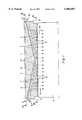
- FIG. 1depicts a vertical section of a liquid distributor according to the invention
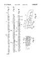
- FIG. 2depicts a wall element of the liquid distributor according to FIG. 1, in horizontal section II--II, of FIG. 1,
- FIG. 3depicts a wall element of the liquid distributor according to FIG. 1, in horizontal section III--III of FIG. 1,
- FIG. 4depicts a wall element of the liquid distributor according to FIG. 1, in horizontal section IV--IV of FIG. 1,
- FIG. 5depicts a partial horizontal section of three wall elements attached one to another, the wall elements forming a distributor for both the liquid to be evaporated and for the heating vapor, and
- FIG. 6depicts on a larger scale the branching points of the conduits of the liquid distributor according to FIG. 1.
- the liquid distributor according to the invention for an evaporatorcomprises a conduit frame which is made up of two vertical wall elements 1, 2, for example, injection molded from a plastic material, these wall elements delimiting between themselves the liquid conduits 3, 4 of the distributor.
- the liquid conduits 3, 4have been produced by forming, in connection with injection molding, recesses in the wall element 1 according to
- FIGS. 1-4and by closing these on their open side by a second wall element 2 in accordance with FIG. 5.
- FIG. 5additionally shows vapor conduits 5 closed by means of a wall element 1 according to FIGS. 1-4, which vapor conduits will be returned to in greater detail hereinafter.
- the liquid conduitswhich can best be seen in FIGS. 1 and 6, comprise a feed conduit 3 starting from the distributor end 6 located on the side of the evaporator, the feed conduit extending obliquely downwards to the middle of the distributor, and a plurality of substantially vertical distribution conduits 4 which branch out from the feed conduit at branching points 7 and lead to the heat exchange surface 5 of the evaporator.
- the width D (cf. FIG. 6) of the distribution conduits 4 branching out from the feed conduit 3may be constant or grow progressively, conduit by conduit, towards the middle of the distributor.
- the distributorcomprises a symmetrically corresponding system of liquid conduits made up of feed and distribution conduits 3, 4.
- the feed flow of the liquid to be evaporatedis directed in accordance with arrows 8 in FIG. 1 to the feed conduits 3, from where it is divided into partial flows according to arrows 9, into the distribution conduits 4 leading to the heat exchange surface, substantially equally among the distribution conduits.
- the liquidcan be distributed from the distribution conduits 4 evenly over the entire width of the heat exchange surface.
- the feed conduit 3Via its end in the middle of the distributor, the feed conduit 3 communicates with the vapor spaces of the evaporator so that during operation the feed conduit is in part filled with vapor 14 formed during evaporation. It is necessary to regulate the feeding in of the liquid to be evaporated in such a manner that the feed conduit 3 is not in its entirety filled with liquid, because otherwise the produced siphon effect would hamper even distribution of the liquid.
- the branching points 7 of the conduits and the division of the liquid flow at them into partial flows passing to the heat exchange surfaceis seen on a larger scale in FIG. 6.
- the feed flow traveling in the feed conduit 3is indicated in the figure by numeral 8 and the partial flows separating into the distribution conduits 4 by numeral 9.
- the wall surface common to the conduits, downstream relative to the feed flow 8is formed into a curved dividing surface 10, the radius of which is indicated by R.
- the wall surface of the distribution conduit 4is rounded correspondingly, and the wall surface of the conduit 4 and the wall surface of the feed conduit 3 together form a sharp feeding tip 11 from which the arriving feed flow 8 jumps over the end of the distribution conduit onto the dividing surface 10, on which the division of the flow takes place at each given point.
- the successive dividing surfaces 10, terminating in feeding tips 11,are dimensioned so that the feeding tip of a dividing surface lower in the direction of the flow is at each given point disposed a few millimeters below the theoretical continuation of the feeding tip of the next dividing surface upstream.
- the impinging angle of the flow 8 to the tangent of the dividing surface 10is indicated in the figure by ⁇ .
- the division of the feed flow 8 into partial flows 9depends on the composition of the liquid, on the radius R of curvature of the dividing surface, and on the impinging angle ⁇ , which in turn is dependent on, for example, the velocity of the flow and the width D of the distribution conduits 4, and the distribution may be regulated by varying the said values.
- the impinging angle ⁇ of the feed flow 8is advantageously set close to a right angle, for example, within a range of approx. 90-110°.
- the liquid conduits 3, 4 in the distributorare located in accordance with FIG. 5 between two wall elements 1, 2 fastened to each other.
- the locking of the elements 1, 2 to each otheris effected by snap fastenings of vertical projections 12 in element 1 according to FIGS. 1-4 to corresponding recesses 13 in the other element 2.
- the heat exchange surfacebeing of plastic membrane, the upper end of the membrane may be locked (not shown) between the elements 1, 2 fastened to each other.
- the said second wall element 2 in FIG. 5is designed so that, together with a third element, element 1 according to FIGS. 1-4, it delimits vertical vapor conduits 5 from which heating vapor is directed to that side of the heat exchange surface which is opposite to the liquid to be evaporated.
- a third element, element 1 according to FIGS. 1-4it delimits vertical vapor conduits 5 from which heating vapor is directed to that side of the heat exchange surface which is opposite to the liquid to be evaporated.
- the heating vaporis directed via conduits 5 to the inside of the bags and the liquid to be evaporated is directed via conduits 3, 4 onto the outer surfaces of the bags.
Landscapes
- Engineering & Computer Science (AREA)
- Chemical & Material Sciences (AREA)
- Chemical Kinetics & Catalysis (AREA)
- Physics & Mathematics (AREA)
- Thermal Sciences (AREA)
- Mechanical Engineering (AREA)
- General Engineering & Computer Science (AREA)
- Vaporization, Distillation, Condensation, Sublimation, And Cold Traps (AREA)
- Heat-Exchange Devices With Radiators And Conduit Assemblies (AREA)
- Details Of Heat-Exchange And Heat-Transfer (AREA)
- Paper (AREA)
- Physical Or Chemical Processes And Apparatus (AREA)
Abstract
Description
Claims (12)
Applications Claiming Priority (3)
| Application Number | Priority Date | Filing Date | Title |
|---|---|---|---|
| FI944471AFI97694C (en) | 1994-09-27 | 1994-09-27 | Liquid distributor for an evaporator |
| FI944471 | 1994-09-27 | ||
| PCT/FI1995/000524WO1996009872A1 (en) | 1994-09-27 | 1995-09-26 | Liquid distributor for an evaporator |
Publications (1)
| Publication Number | Publication Date |
|---|---|
| US5904807Atrue US5904807A (en) | 1999-05-18 |
Family
ID=8541452
Family Applications (1)
| Application Number | Title | Priority Date | Filing Date |
|---|---|---|---|
| US08/809,775Expired - LifetimeUS5904807A (en) | 1994-09-27 | 1995-09-26 | Liquid distributor for an evaporator |
Country Status (15)
| Country | Link |
|---|---|
| US (1) | US5904807A (en) |
| EP (1) | EP0783359B1 (en) |
| JP (1) | JP3916657B2 (en) |
| KR (1) | KR100385623B1 (en) |
| AT (1) | ATE198837T1 (en) |
| AU (1) | AU689957B2 (en) |
| BR (1) | BR9509106A (en) |
| DE (1) | DE69519992T2 (en) |
| DK (1) | DK0783359T3 (en) |
| ES (1) | ES2155529T3 (en) |
| FI (1) | FI97694C (en) |
| GR (1) | GR3035464T3 (en) |
| NO (1) | NO971427D0 (en) |
| PT (1) | PT783359E (en) |
| WO (1) | WO1996009872A1 (en) |
Cited By (18)
| Publication number | Priority date | Publication date | Assignee | Title |
|---|---|---|---|---|
| US6047484A (en)* | 1998-07-10 | 2000-04-11 | Bolland; Karin Marie | Method and apparatus for evaporating liquid from a product |
| US6066232A (en)* | 1996-01-25 | 2000-05-23 | Basf Aktiengesellschaft | Method and vaporizer for vaporizing oxidation-sensitive compounds |
| US6068730A (en)* | 1995-08-22 | 2000-05-30 | Hadwaco Ltd Oy | Liquid distributor for evaporator |
| US20020003037A1 (en)* | 1997-12-31 | 2002-01-10 | Cousineau Shawn M. | Temperature-controlled chuck with recovery of circulating temperature control fluid |
| US20020041839A1 (en)* | 2000-08-12 | 2002-04-11 | Roland Cwik | Device for feeding educts to parallel spaces |
| US6395139B1 (en)* | 1998-10-30 | 2002-05-28 | The Boc Group, Inc. | Feed distributor for a liquid distributor of a distillation column |
| US6395138B1 (en)* | 1997-11-17 | 2002-05-28 | L'air Liquide, Societe Anonyme A Directoire Et Conseil De Surveillance Pour L'etude Et L'exploitation Des Procedes Georges Claude | Liquid dispenser for distilling column, and corresponding distilling column |
| US6780281B1 (en)* | 1999-11-29 | 2004-08-24 | Bayer Aktiengesellschaft | Strand evaporator |
| US6802368B2 (en) | 1997-12-31 | 2004-10-12 | Temptronic Corporation | Temperature control system for a workpiece chuck |
| US20050011768A1 (en)* | 1997-12-31 | 2005-01-20 | Stone William M. | Workpiece chuck |
| US20050098424A1 (en)* | 2000-09-06 | 2005-05-12 | Mount Dennis W. | Anti-pressure system |
| US20080149311A1 (en)* | 2006-12-21 | 2008-06-26 | Industrial Technology Research Institute | Spray type heat exchange device |
| US20080196839A1 (en)* | 2004-09-17 | 2008-08-21 | Peter Porscha | Partial Load Enabled Falling Film Evaporator and Method for Operating a Partial Load |
| US20100276820A1 (en)* | 2008-01-10 | 2010-11-04 | Ms Grow Up Corp. | Static fluid mixer |
| CN102079463A (en)* | 2009-11-26 | 2011-06-01 | 江南大学 | Novel combined yarn collecting spindle |
| US20120097362A1 (en)* | 2009-03-27 | 2012-04-26 | Framo Engineering As | Subsea cooler and method for cleaning the subsea cooler |
| US20130146226A1 (en)* | 2010-03-08 | 2013-06-13 | Arvind Accel Limited | Heat exchange element, a heat exchanger comprising the elements, and an equipment for the manufacture of the elements |
| CN104043258A (en)* | 2014-06-25 | 2014-09-17 | 江苏中圣高科技产业有限公司 | Liquid distributor for evaporator |
Families Citing this family (5)
| Publication number | Priority date | Publication date | Assignee | Title |
|---|---|---|---|---|
| KR100866299B1 (en) | 2004-12-15 | 2008-10-31 | 아사히 가세이 케미칼즈 가부시키가이샤 | Industrial evaporator |
| US20080017325A1 (en)* | 2004-12-20 | 2008-01-24 | Shinsuke Fukuoka | Industrial Evaporation Apparatus |
| FR2938904B1 (en)* | 2008-11-24 | 2012-05-04 | Air Liquide | HEAT EXCHANGER |
| JP5761593B2 (en)* | 2011-02-10 | 2015-08-12 | 株式会社リコー | Heat exchange apparatus and image forming apparatus |
| JP5953121B2 (en)* | 2012-05-25 | 2016-07-20 | 株式会社クレハ | Packed column equipped with a re-disperser for packed column and method for distillation of vinylidene chloride monomer using the same |
Citations (12)
| Publication number | Priority date | Publication date | Assignee | Title |
|---|---|---|---|---|
| US709297A (en)* | 1901-06-11 | 1902-09-16 | Firm Of Zellstofffabrik Dueren Hermann Maria Schoeller & Co | Evaporator. |
| US1249557A (en)* | 1916-09-05 | 1917-12-11 | Harold Sage Truscott | Calandria for vacuum drying-pans and the like. |
| US3290024A (en)* | 1964-03-19 | 1966-12-06 | Sulzer Ag | Material exchange column |
| DE1519741A1 (en)* | 1965-06-03 | 1970-03-12 | Wiegand Appbau Gmbh | Device for even distribution of the liquid on the heating pipes of falling film evaporators |
| US3794056A (en)* | 1972-11-17 | 1974-02-26 | R Warren | Fluidic pulse and flow divider |
| US3849232A (en)* | 1972-03-16 | 1974-11-19 | Wiegand Karlsruhe Gmbh | Falling film evaporator |
| US4277425A (en)* | 1978-03-17 | 1981-07-07 | Max Leva | Tower packing element |
| WO1990001977A1 (en)* | 1988-08-26 | 1990-03-08 | Aquamax Oy | A distillation apparatus |
| WO1995008381A1 (en)* | 1993-09-22 | 1995-03-30 | Oy Shippax Ltd. | Fluid distributor of a membrane distiller and the use of the distiller |
| US5512141A (en)* | 1990-12-14 | 1996-04-30 | Keeran Corporation N.V. | Distillation apparatus |
| US5755924A (en)* | 1995-09-02 | 1998-05-26 | Feres; Vaclav | Apparatus for treating liquid products |
| US5770020A (en)* | 1990-12-14 | 1998-06-23 | Keeran Corporation N.V. | Distillation apparatus |
- 1994
- 1994-09-27FIFI944471Apatent/FI97694C/ennot_activeIP Right Cessation
- 1995
- 1995-09-26AUAU35237/95Apatent/AU689957B2/ennot_activeCeased
- 1995-09-26KRKR1019970701951Apatent/KR100385623B1/ennot_activeExpired - Fee Related
- 1995-09-26PTPT95932029Tpatent/PT783359E/enunknown
- 1995-09-26BRBR9509106Apatent/BR9509106A/ennot_activeIP Right Cessation
- 1995-09-26WOPCT/FI1995/000524patent/WO1996009872A1/enactiveIP Right Grant
- 1995-09-26EPEP95932029Apatent/EP0783359B1/ennot_activeExpired - Lifetime
- 1995-09-26ESES95932029Tpatent/ES2155529T3/ennot_activeExpired - Lifetime
- 1995-09-26USUS08/809,775patent/US5904807A/ennot_activeExpired - Lifetime
- 1995-09-26ATAT95932029Tpatent/ATE198837T1/ennot_activeIP Right Cessation
- 1995-09-26JPJP51116496Apatent/JP3916657B2/ennot_activeExpired - Fee Related
- 1995-09-26DKDK95932029Tpatent/DK0783359T3/enactive
- 1995-09-26DEDE69519992Tpatent/DE69519992T2/ennot_activeExpired - Fee Related
- 1997
- 1997-03-25NONO971427Apatent/NO971427D0/ennot_activeApplication Discontinuation
- 2001
- 2001-02-22GRGR20010400298Tpatent/GR3035464T3/ennot_activeIP Right Cessation
Patent Citations (12)
| Publication number | Priority date | Publication date | Assignee | Title |
|---|---|---|---|---|
| US709297A (en)* | 1901-06-11 | 1902-09-16 | Firm Of Zellstofffabrik Dueren Hermann Maria Schoeller & Co | Evaporator. |
| US1249557A (en)* | 1916-09-05 | 1917-12-11 | Harold Sage Truscott | Calandria for vacuum drying-pans and the like. |
| US3290024A (en)* | 1964-03-19 | 1966-12-06 | Sulzer Ag | Material exchange column |
| DE1519741A1 (en)* | 1965-06-03 | 1970-03-12 | Wiegand Appbau Gmbh | Device for even distribution of the liquid on the heating pipes of falling film evaporators |
| US3849232A (en)* | 1972-03-16 | 1974-11-19 | Wiegand Karlsruhe Gmbh | Falling film evaporator |
| US3794056A (en)* | 1972-11-17 | 1974-02-26 | R Warren | Fluidic pulse and flow divider |
| US4277425A (en)* | 1978-03-17 | 1981-07-07 | Max Leva | Tower packing element |
| WO1990001977A1 (en)* | 1988-08-26 | 1990-03-08 | Aquamax Oy | A distillation apparatus |
| US5512141A (en)* | 1990-12-14 | 1996-04-30 | Keeran Corporation N.V. | Distillation apparatus |
| US5770020A (en)* | 1990-12-14 | 1998-06-23 | Keeran Corporation N.V. | Distillation apparatus |
| WO1995008381A1 (en)* | 1993-09-22 | 1995-03-30 | Oy Shippax Ltd. | Fluid distributor of a membrane distiller and the use of the distiller |
| US5755924A (en)* | 1995-09-02 | 1998-05-26 | Feres; Vaclav | Apparatus for treating liquid products |
Cited By (27)
| Publication number | Priority date | Publication date | Assignee | Title |
|---|---|---|---|---|
| US6068730A (en)* | 1995-08-22 | 2000-05-30 | Hadwaco Ltd Oy | Liquid distributor for evaporator |
| US6066232A (en)* | 1996-01-25 | 2000-05-23 | Basf Aktiengesellschaft | Method and vaporizer for vaporizing oxidation-sensitive compounds |
| US6395138B1 (en)* | 1997-11-17 | 2002-05-28 | L'air Liquide, Societe Anonyme A Directoire Et Conseil De Surveillance Pour L'etude Et L'exploitation Des Procedes Georges Claude | Liquid dispenser for distilling column, and corresponding distilling column |
| US20020003037A1 (en)* | 1997-12-31 | 2002-01-10 | Cousineau Shawn M. | Temperature-controlled chuck with recovery of circulating temperature control fluid |
| US7331097B2 (en) | 1997-12-31 | 2008-02-19 | Temptronic Corporation | Method of manufacturing a workpiece chuck |
| US6802368B2 (en) | 1997-12-31 | 2004-10-12 | Temptronic Corporation | Temperature control system for a workpiece chuck |
| US20050011768A1 (en)* | 1997-12-31 | 2005-01-20 | Stone William M. | Workpiece chuck |
| US6866094B2 (en) | 1997-12-31 | 2005-03-15 | Temptronic Corporation | Temperature-controlled chuck with recovery of circulating temperature control fluid |
| US6047484A (en)* | 1998-07-10 | 2000-04-11 | Bolland; Karin Marie | Method and apparatus for evaporating liquid from a product |
| US6395139B1 (en)* | 1998-10-30 | 2002-05-28 | The Boc Group, Inc. | Feed distributor for a liquid distributor of a distillation column |
| US6780281B1 (en)* | 1999-11-29 | 2004-08-24 | Bayer Aktiengesellschaft | Strand evaporator |
| WO2002005325A3 (en)* | 2000-07-11 | 2003-02-20 | Temptronic Corp | Chuck with heat exchanger and temperature control fluid |
| US20020041839A1 (en)* | 2000-08-12 | 2002-04-11 | Roland Cwik | Device for feeding educts to parallel spaces |
| US7001575B2 (en)* | 2000-08-12 | 2006-02-21 | Nucellsys Gmbh | Device for feeding educts to parallel spaces |
| US20050098424A1 (en)* | 2000-09-06 | 2005-05-12 | Mount Dennis W. | Anti-pressure system |
| US7368038B2 (en)* | 2000-09-06 | 2008-05-06 | Chem-Champ (Barbados) Inc. | Anti-pressure system |
| US20080196839A1 (en)* | 2004-09-17 | 2008-08-21 | Peter Porscha | Partial Load Enabled Falling Film Evaporator and Method for Operating a Partial Load |
| US7959768B2 (en)* | 2004-09-17 | 2011-06-14 | Uhde Gmbh | Partial load enabled falling film evaporator and method for operating a partial load |
| US20080149311A1 (en)* | 2006-12-21 | 2008-06-26 | Industrial Technology Research Institute | Spray type heat exchange device |
| US20100276820A1 (en)* | 2008-01-10 | 2010-11-04 | Ms Grow Up Corp. | Static fluid mixer |
| US8740450B2 (en)* | 2008-01-10 | 2014-06-03 | Mg Grow Up Corp. | Static fluid mixer capable of ultrafinely mixing fluids |
| US20120097362A1 (en)* | 2009-03-27 | 2012-04-26 | Framo Engineering As | Subsea cooler and method for cleaning the subsea cooler |
| US9303491B2 (en)* | 2009-03-27 | 2016-04-05 | Framo Engineering As | Subsea cooler and method for cleaning the subsea cooler |
| CN102079463A (en)* | 2009-11-26 | 2011-06-01 | 江南大学 | Novel combined yarn collecting spindle |
| US20130146226A1 (en)* | 2010-03-08 | 2013-06-13 | Arvind Accel Limited | Heat exchange element, a heat exchanger comprising the elements, and an equipment for the manufacture of the elements |
| US9372033B2 (en)* | 2010-03-08 | 2016-06-21 | Arvind Accel Limited | Heat exchange element, a heat exchanger comprising the elements, and an equipment for the manufacture of the elements |
| CN104043258A (en)* | 2014-06-25 | 2014-09-17 | 江苏中圣高科技产业有限公司 | Liquid distributor for evaporator |
Also Published As
| Publication number | Publication date |
|---|---|
| EP0783359B1 (en) | 2001-01-24 |
| AU689957B2 (en) | 1998-04-09 |
| BR9509106A (en) | 1998-11-03 |
| DK0783359T3 (en) | 2001-02-05 |
| FI97694C (en) | 1997-02-10 |
| KR970706049A (en) | 1997-11-03 |
| FI944471L (en) | 1996-03-28 |
| AU3523795A (en) | 1996-04-19 |
| FI97694B (en) | 1996-10-31 |
| WO1996009872A1 (en) | 1996-04-04 |
| NO971427L (en) | 1997-03-25 |
| GR3035464T3 (en) | 2001-05-31 |
| JP3916657B2 (en) | 2007-05-16 |
| JPH10506050A (en) | 1998-06-16 |
| EP0783359A1 (en) | 1997-07-16 |
| ATE198837T1 (en) | 2001-02-15 |
| KR100385623B1 (en) | 2003-08-14 |
| DE69519992T2 (en) | 2001-06-07 |
| FI944471A0 (en) | 1994-09-27 |
| NO971427D0 (en) | 1997-03-25 |
| DE69519992D1 (en) | 2001-03-01 |
| PT783359E (en) | 2001-05-31 |
| ES2155529T3 (en) | 2001-05-16 |
Similar Documents
| Publication | Publication Date | Title |
|---|---|---|
| US5904807A (en) | Liquid distributor for an evaporator | |
| KR100232015B1 (en) | Distillation apparatus | |
| US4154642A (en) | Falling film evaporator | |
| CA1218011A (en) | Device for gravimetric distribution of liquid for mass and heat transfer columns | |
| US6068730A (en) | Liquid distributor for evaporator | |
| AU601394B2 (en) | A method of an apparatus for achieving uniform distribution of a solids-containing liquid over a cross-sectional area | |
| CA2035506C (en) | Device for the recovery of a processed liquid in the form of a condensate on a liquid to be processed | |
| CA1325967C (en) | Process and apparatus for concentrating solutions | |
| HUT76179A (en) | Distillation plant | |
| CA2200948C (en) | Liquid distributor for an evaporator | |
| US3984281A (en) | Plate type liquid heater and evaporator | |
| US4878535A (en) | Selective condensation apparatus | |
| WO1995008381A1 (en) | Fluid distributor of a membrane distiller and the use of the distiller | |
| US6241010B1 (en) | Heat exchange element and a heat exchanger made up of the same | |
| US5724922A (en) | Low-temperature steam generator | |
| FI106297B (en) | Process for evaporation of a solution and evaporator intended for use in the process | |
| CA2157165C (en) | Column baffles for suspensions with precipitating substances | |
| CN110478937A (en) | A kind of crystallizer and crystal system | |
| US5938896A (en) | Hydraulic increaser for a wet end of a paper-making machine | |
| US635876A (en) | Evaporating-pan. | |
| JPH11319543A (en) | Reduced-pressure vapor heating device | |
| DD276026A1 (en) | DEVICE FOR DIRT AND EXHAUST TREATMENT IN OVEN | |
| CS218771B1 (en) | Nozzle system for heat treatment of flats on machines for processing textiles, paper, plastics and other similar materials |
Legal Events
| Date | Code | Title | Description |
|---|---|---|---|
| AS | Assignment | Owner name:HADWACO LTD. OY, FINLAND Free format text:ASSIGNMENT OF ASSIGNORS INTEREST;ASSIGNORS:RAMM-SCHMIDT, LEIF;ERIKSSON, HEMMO;KOISTINEN, PETER;AND OTHERS;REEL/FRAME:008563/0721 Effective date:19970523 | |
| FEPP | Fee payment procedure | Free format text:PAYOR NUMBER ASSIGNED (ORIGINAL EVENT CODE: ASPN); ENTITY STATUS OF PATENT OWNER: LARGE ENTITY | |
| STCF | Information on status: patent grant | Free format text:PATENTED CASE | |
| FEPP | Fee payment procedure | Free format text:PAYOR NUMBER ASSIGNED (ORIGINAL EVENT CODE: ASPN); ENTITY STATUS OF PATENT OWNER: LARGE ENTITY Free format text:PAYER NUMBER DE-ASSIGNED (ORIGINAL EVENT CODE: RMPN); ENTITY STATUS OF PATENT OWNER: LARGE ENTITY | |
| FPAY | Fee payment | Year of fee payment:4 | |
| REMI | Maintenance fee reminder mailed | ||
| AS | Assignment | Owner name:HADWACO TECHNOLOGIES OY, FINLAND Free format text:CHANGE OF NAME;ASSIGNOR:OY CASPARADO AB;REEL/FRAME:014499/0426 Effective date:20030324 Owner name:OY CASPARADO AB, FINLAND Free format text:ASSIGNMENT OF ASSIGNORS INTEREST;ASSIGNOR:HADWACO LTD. OY;REEL/FRAME:014499/0049 Effective date:20030214 | |
| AS | Assignment | Owner name:EBARA CORPORATION, JAPAN Free format text:ASSIGNMENT OF ASSIGNORS INTEREST;ASSIGNOR:HADWACO TECHNOLOGIES OY;REEL/FRAME:018148/0767 Effective date:20060510 | |
| FPAY | Fee payment | Year of fee payment:8 | |
| AS | Assignment | Owner name:EBARA ENGINEERING SERVICE CO., LTD.,JAPAN Free format text:ASSIGNMENT OF ASSIGNORS INTEREST;ASSIGNOR:EBARA CORPORATION;REEL/FRAME:023985/0462 Effective date:20100223 | |
| FPAY | Fee payment | Year of fee payment:12 |