US5904679A - Catheter with electrosurgical cutter - Google Patents
Catheter with electrosurgical cutterDownload PDFInfo
- Publication number
- US5904679A US5904679AUS08/216,512US21651294AUS5904679AUS 5904679 AUS5904679 AUS 5904679AUS 21651294 AUS21651294 AUS 21651294AUS 5904679 AUS5904679 AUS 5904679A
- Authority
- US
- United States
- Prior art keywords
- catheter
- tissue
- wire
- balloon
- portions
- Prior art date
- Legal status (The legal status is an assumption and is not a legal conclusion. Google has not performed a legal analysis and makes no representation as to the accuracy of the status listed.)
- Expired - Lifetime
Links
Images

Classifications
- A—HUMAN NECESSITIES
- A61—MEDICAL OR VETERINARY SCIENCE; HYGIENE
- A61B—DIAGNOSIS; SURGERY; IDENTIFICATION
- A61B17/00—Surgical instruments, devices or methods
- A61B17/22—Implements for squeezing-off ulcers or the like on inner organs of the body; Implements for scraping-out cavities of body organs, e.g. bones; for invasive removal or destruction of calculus using mechanical vibrations; for removing obstructions in blood vessels, not otherwise provided for
- A—HUMAN NECESSITIES
- A61—MEDICAL OR VETERINARY SCIENCE; HYGIENE
- A61B—DIAGNOSIS; SURGERY; IDENTIFICATION
- A61B17/00—Surgical instruments, devices or methods
- A61B17/32—Surgical cutting instruments
- A61B17/3205—Excision instruments
- A61B17/3207—Atherectomy devices working by cutting or abrading; Similar devices specially adapted for non-vascular obstructions
- A61B17/320725—Atherectomy devices working by cutting or abrading; Similar devices specially adapted for non-vascular obstructions with radially expandable cutting or abrading elements
- A—HUMAN NECESSITIES
- A61—MEDICAL OR VETERINARY SCIENCE; HYGIENE
- A61B—DIAGNOSIS; SURGERY; IDENTIFICATION
- A61B18/00—Surgical instruments, devices or methods for transferring non-mechanical forms of energy to or from the body
- A61B18/04—Surgical instruments, devices or methods for transferring non-mechanical forms of energy to or from the body by heating
- A61B18/08—Surgical instruments, devices or methods for transferring non-mechanical forms of energy to or from the body by heating by means of electrically-heated probes
- A61B18/082—Probes or electrodes therefor
- A—HUMAN NECESSITIES
- A61—MEDICAL OR VETERINARY SCIENCE; HYGIENE
- A61B—DIAGNOSIS; SURGERY; IDENTIFICATION
- A61B18/00—Surgical instruments, devices or methods for transferring non-mechanical forms of energy to or from the body
- A61B18/04—Surgical instruments, devices or methods for transferring non-mechanical forms of energy to or from the body by heating
- A61B18/12—Surgical instruments, devices or methods for transferring non-mechanical forms of energy to or from the body by heating by passing a current through the tissue to be heated, e.g. high-frequency current
- A61B18/14—Probes or electrodes therefor
- A61B18/1492—Probes or electrodes therefor having a flexible, catheter-like structure, e.g. for heart ablation
- A—HUMAN NECESSITIES
- A61—MEDICAL OR VETERINARY SCIENCE; HYGIENE
- A61M—DEVICES FOR INTRODUCING MEDIA INTO, OR ONTO, THE BODY; DEVICES FOR TRANSDUCING BODY MEDIA OR FOR TAKING MEDIA FROM THE BODY; DEVICES FOR PRODUCING OR ENDING SLEEP OR STUPOR
- A61M25/00—Catheters; Hollow probes
- A61M25/10—Balloon catheters
- A61M25/104—Balloon catheters used for angioplasty
- A—HUMAN NECESSITIES
- A61—MEDICAL OR VETERINARY SCIENCE; HYGIENE
- A61B—DIAGNOSIS; SURGERY; IDENTIFICATION
- A61B18/00—Surgical instruments, devices or methods for transferring non-mechanical forms of energy to or from the body
- A61B18/18—Surgical instruments, devices or methods for transferring non-mechanical forms of energy to or from the body by applying electromagnetic radiation, e.g. microwaves
- A61B18/1815—Surgical instruments, devices or methods for transferring non-mechanical forms of energy to or from the body by applying electromagnetic radiation, e.g. microwaves using microwaves
- A—HUMAN NECESSITIES
- A61—MEDICAL OR VETERINARY SCIENCE; HYGIENE
- A61B—DIAGNOSIS; SURGERY; IDENTIFICATION
- A61B17/00—Surgical instruments, devices or methods
- A61B17/00234—Surgical instruments, devices or methods for minimally invasive surgery
- A61B2017/00292—Surgical instruments, devices or methods for minimally invasive surgery mounted on or guided by flexible, e.g. catheter-like, means
- A—HUMAN NECESSITIES
- A61—MEDICAL OR VETERINARY SCIENCE; HYGIENE
- A61B—DIAGNOSIS; SURGERY; IDENTIFICATION
- A61B17/00—Surgical instruments, devices or methods
- A61B17/22—Implements for squeezing-off ulcers or the like on inner organs of the body; Implements for scraping-out cavities of body organs, e.g. bones; for invasive removal or destruction of calculus using mechanical vibrations; for removing obstructions in blood vessels, not otherwise provided for
- A61B2017/22051—Implements for squeezing-off ulcers or the like on inner organs of the body; Implements for scraping-out cavities of body organs, e.g. bones; for invasive removal or destruction of calculus using mechanical vibrations; for removing obstructions in blood vessels, not otherwise provided for with an inflatable part, e.g. balloon, for positioning, blocking, or immobilisation
- A61B2017/22061—Implements for squeezing-off ulcers or the like on inner organs of the body; Implements for scraping-out cavities of body organs, e.g. bones; for invasive removal or destruction of calculus using mechanical vibrations; for removing obstructions in blood vessels, not otherwise provided for with an inflatable part, e.g. balloon, for positioning, blocking, or immobilisation for spreading elements apart
- A—HUMAN NECESSITIES
- A61—MEDICAL OR VETERINARY SCIENCE; HYGIENE
- A61B—DIAGNOSIS; SURGERY; IDENTIFICATION
- A61B17/00—Surgical instruments, devices or methods
- A61B17/22—Implements for squeezing-off ulcers or the like on inner organs of the body; Implements for scraping-out cavities of body organs, e.g. bones; for invasive removal or destruction of calculus using mechanical vibrations; for removing obstructions in blood vessels, not otherwise provided for
- A61B2017/22051—Implements for squeezing-off ulcers or the like on inner organs of the body; Implements for scraping-out cavities of body organs, e.g. bones; for invasive removal or destruction of calculus using mechanical vibrations; for removing obstructions in blood vessels, not otherwise provided for with an inflatable part, e.g. balloon, for positioning, blocking, or immobilisation
- A61B2017/22062—Implements for squeezing-off ulcers or the like on inner organs of the body; Implements for scraping-out cavities of body organs, e.g. bones; for invasive removal or destruction of calculus using mechanical vibrations; for removing obstructions in blood vessels, not otherwise provided for with an inflatable part, e.g. balloon, for positioning, blocking, or immobilisation to be filled with liquid
- A—HUMAN NECESSITIES
- A61—MEDICAL OR VETERINARY SCIENCE; HYGIENE
- A61B—DIAGNOSIS; SURGERY; IDENTIFICATION
- A61B18/00—Surgical instruments, devices or methods for transferring non-mechanical forms of energy to or from the body
- A61B2018/00053—Mechanical features of the instrument of device
- A61B2018/00107—Coatings on the energy applicator
- A61B2018/00148—Coatings on the energy applicator with metal
- A—HUMAN NECESSITIES
- A61—MEDICAL OR VETERINARY SCIENCE; HYGIENE
- A61B—DIAGNOSIS; SURGERY; IDENTIFICATION
- A61B18/00—Surgical instruments, devices or methods for transferring non-mechanical forms of energy to or from the body
- A61B2018/00053—Mechanical features of the instrument of device
- A61B2018/00184—Moving parts
- A61B2018/00196—Moving parts reciprocating lengthwise
- A—HUMAN NECESSITIES
- A61—MEDICAL OR VETERINARY SCIENCE; HYGIENE
- A61B—DIAGNOSIS; SURGERY; IDENTIFICATION
- A61B18/00—Surgical instruments, devices or methods for transferring non-mechanical forms of energy to or from the body
- A61B2018/00053—Mechanical features of the instrument of device
- A61B2018/00214—Expandable means emitting energy, e.g. by elements carried thereon
- A61B2018/0022—Balloons
- A—HUMAN NECESSITIES
- A61—MEDICAL OR VETERINARY SCIENCE; HYGIENE
- A61B—DIAGNOSIS; SURGERY; IDENTIFICATION
- A61B18/00—Surgical instruments, devices or methods for transferring non-mechanical forms of energy to or from the body
- A61B2018/00053—Mechanical features of the instrument of device
- A61B2018/00273—Anchoring means for temporary attachment of a device to tissue
- A61B2018/00279—Anchoring means for temporary attachment of a device to tissue deployable
- A61B2018/00285—Balloons
- A—HUMAN NECESSITIES
- A61—MEDICAL OR VETERINARY SCIENCE; HYGIENE
- A61B—DIAGNOSIS; SURGERY; IDENTIFICATION
- A61B18/00—Surgical instruments, devices or methods for transferring non-mechanical forms of energy to or from the body
- A61B2018/00315—Surgical instruments, devices or methods for transferring non-mechanical forms of energy to or from the body for treatment of particular body parts
- A61B2018/00345—Vascular system
- A61B2018/00351—Heart
- A61B2018/00386—Coronary vessels
- A—HUMAN NECESSITIES
- A61—MEDICAL OR VETERINARY SCIENCE; HYGIENE
- A61B—DIAGNOSIS; SURGERY; IDENTIFICATION
- A61B18/00—Surgical instruments, devices or methods for transferring non-mechanical forms of energy to or from the body
- A61B2018/00315—Surgical instruments, devices or methods for transferring non-mechanical forms of energy to or from the body for treatment of particular body parts
- A61B2018/00345—Vascular system
- A61B2018/00404—Blood vessels other than those in or around the heart
- A61B2018/00422—Angioplasty
- A—HUMAN NECESSITIES
- A61—MEDICAL OR VETERINARY SCIENCE; HYGIENE
- A61B—DIAGNOSIS; SURGERY; IDENTIFICATION
- A61B18/00—Surgical instruments, devices or methods for transferring non-mechanical forms of energy to or from the body
- A61B18/04—Surgical instruments, devices or methods for transferring non-mechanical forms of energy to or from the body by heating
- A61B18/12—Surgical instruments, devices or methods for transferring non-mechanical forms of energy to or from the body by heating by passing a current through the tissue to be heated, e.g. high-frequency current
- A61B18/1206—Generators therefor
- A61B2018/1213—Generators therefor creating an arc
- A—HUMAN NECESSITIES
- A61—MEDICAL OR VETERINARY SCIENCE; HYGIENE
- A61B—DIAGNOSIS; SURGERY; IDENTIFICATION
- A61B18/00—Surgical instruments, devices or methods for transferring non-mechanical forms of energy to or from the body
- A61B18/04—Surgical instruments, devices or methods for transferring non-mechanical forms of energy to or from the body by heating
- A61B18/12—Surgical instruments, devices or methods for transferring non-mechanical forms of energy to or from the body by heating by passing a current through the tissue to be heated, e.g. high-frequency current
- A61B18/1206—Generators therefor
- A61B2018/1246—Generators therefor characterised by the output polarity
- A61B2018/1253—Generators therefor characterised by the output polarity monopolar
- A—HUMAN NECESSITIES
- A61—MEDICAL OR VETERINARY SCIENCE; HYGIENE
- A61B—DIAGNOSIS; SURGERY; IDENTIFICATION
- A61B18/00—Surgical instruments, devices or methods for transferring non-mechanical forms of energy to or from the body
- A61B18/04—Surgical instruments, devices or methods for transferring non-mechanical forms of energy to or from the body by heating
- A61B18/12—Surgical instruments, devices or methods for transferring non-mechanical forms of energy to or from the body by heating by passing a current through the tissue to be heated, e.g. high-frequency current
- A61B18/14—Probes or electrodes therefor
- A61B2018/1405—Electrodes having a specific shape
- A61B2018/1407—Loop
- A—HUMAN NECESSITIES
- A61—MEDICAL OR VETERINARY SCIENCE; HYGIENE
- A61B—DIAGNOSIS; SURGERY; IDENTIFICATION
- A61B18/00—Surgical instruments, devices or methods for transferring non-mechanical forms of energy to or from the body
- A61B18/04—Surgical instruments, devices or methods for transferring non-mechanical forms of energy to or from the body by heating
- A61B18/12—Surgical instruments, devices or methods for transferring non-mechanical forms of energy to or from the body by heating by passing a current through the tissue to be heated, e.g. high-frequency current
- A61B18/14—Probes or electrodes therefor
- A61B2018/1405—Electrodes having a specific shape
- A61B2018/144—Wire
- A—HUMAN NECESSITIES
- A61—MEDICAL OR VETERINARY SCIENCE; HYGIENE
- A61B—DIAGNOSIS; SURGERY; IDENTIFICATION
- A61B18/00—Surgical instruments, devices or methods for transferring non-mechanical forms of energy to or from the body
- A61B18/04—Surgical instruments, devices or methods for transferring non-mechanical forms of energy to or from the body by heating
- A61B18/12—Surgical instruments, devices or methods for transferring non-mechanical forms of energy to or from the body by heating by passing a current through the tissue to be heated, e.g. high-frequency current
- A61B18/14—Probes or electrodes therefor
- A61B2018/1475—Electrodes retractable in or deployable from a housing
- A—HUMAN NECESSITIES
- A61—MEDICAL OR VETERINARY SCIENCE; HYGIENE
- A61M—DEVICES FOR INTRODUCING MEDIA INTO, OR ONTO, THE BODY; DEVICES FOR TRANSDUCING BODY MEDIA OR FOR TAKING MEDIA FROM THE BODY; DEVICES FOR PRODUCING OR ENDING SLEEP OR STUPOR
- A61M25/00—Catheters; Hollow probes
- A61M25/10—Balloon catheters
- A61M2025/1043—Balloon catheters with special features or adapted for special applications
- A61M2025/1093—Balloon catheters with special features or adapted for special applications having particular tip characteristics
- A—HUMAN NECESSITIES
- A61—MEDICAL OR VETERINARY SCIENCE; HYGIENE
- A61M—DEVICES FOR INTRODUCING MEDIA INTO, OR ONTO, THE BODY; DEVICES FOR TRANSDUCING BODY MEDIA OR FOR TAKING MEDIA FROM THE BODY; DEVICES FOR PRODUCING OR ENDING SLEEP OR STUPOR
- A61M2205/00—General characteristics of the apparatus
- A61M2205/32—General characteristics of the apparatus with radio-opaque indicia
- A—HUMAN NECESSITIES
- A61—MEDICAL OR VETERINARY SCIENCE; HYGIENE
- A61M—DEVICES FOR INTRODUCING MEDIA INTO, OR ONTO, THE BODY; DEVICES FOR TRANSDUCING BODY MEDIA OR FOR TAKING MEDIA FROM THE BODY; DEVICES FOR PRODUCING OR ENDING SLEEP OR STUPOR
- A61M25/00—Catheters; Hollow probes
- A61M25/01—Introducing, guiding, advancing, emplacing or holding catheters
- A61M25/09—Guide wires
- A—HUMAN NECESSITIES
- A61—MEDICAL OR VETERINARY SCIENCE; HYGIENE
- A61M—DEVICES FOR INTRODUCING MEDIA INTO, OR ONTO, THE BODY; DEVICES FOR TRANSDUCING BODY MEDIA OR FOR TAKING MEDIA FROM THE BODY; DEVICES FOR PRODUCING OR ENDING SLEEP OR STUPOR
- A61M29/00—Dilators with or without means for introducing media, e.g. remedies
- A61M29/02—Dilators made of swellable material
- A—HUMAN NECESSITIES
- A61—MEDICAL OR VETERINARY SCIENCE; HYGIENE
- A61M—DEVICES FOR INTRODUCING MEDIA INTO, OR ONTO, THE BODY; DEVICES FOR TRANSDUCING BODY MEDIA OR FOR TAKING MEDIA FROM THE BODY; DEVICES FOR PRODUCING OR ENDING SLEEP OR STUPOR
- A61M3/00—Medical syringes, e.g. enemata; Irrigators
- A61M3/02—Enemata; Irrigators
- A61M3/0279—Cannula; Nozzles; Tips; their connection means
Definitions
- the present inventionrelates generally to the field of surgical devices and more specifically to electrosurgical devices adapted to incise body tissue.
- radiofrequency electrosurgical cuttinga radiofrequency current is allowed to pass from an active cutting electrode through a patient's tissue and into a grounding pad or cable.
- the currentcuts tissue at the active cutting electrode, the cutting rate being dependant on current density through the tissue in that area. With a low current density heat is generated but no cut is achieved. With a high current density fast cutting occurs.
- the series impedanceis dependent upon several factors which are outside the control of the surgeon. These factors may include the material and design of the active electrode, the type of tissue to be cut, and the location of the grounding pad relative to the cutting site. Generators used in this type of surgery have a wide range of power output to accommodate a variety of procedures and devices. For example, the generator can be adjusted to either cut tissue or to merely cauterize previously cut or torn tissue.
- the objective in electrosurgical cuttingis to heat the cells of the tissue so rapidly that they explode into steam leaving a cavity in the cell matrix.
- the heatis meant to be dissipated in the steam and not to dry out adjacent cells.
- the current utilized in electrosurgical cuttingis in the radiofrequency range and operates by jumping across an air gap to the tissue. This is commonly referred to as sparking.
- An advantage of electrosurgical cutting, particularly if it is performed utilizing a cutting electrode as disclosed in application Ser. No. 07/522,254 filed May 11, 1990, now U.S. Pat. No. 5,080,660is that overheating of adjacent tissue with accompanying desiccation and damage is limited or prevented. Thus, this procedure provides a clean cut without damage to adjacent tissue. A clean controlled cut is particularly desirable to assure that tearing does not occur in a direction away from the desired orientation of the cut.
- Dilatation cathetersare used to dilate body vessels, orifices and conduits such as an artery narrowed by atherosclerotic plaque or a urethra constricted by an enlarged prostate. These catheters basically consist of an elongate cannula having an inflatable non-extensible balloon or bladder at or near its distal end. A guide wire or other axial support means is often included to improve the torque control or "steerablilty" of the catheter.
- a principal object of the present inventionis to provide a dilatation catheter that permits tissue to be stressed, even beyond its limit of deformability, without experiencing uncontrolled tearing and the undesirable conditions associated therewith.
- Soviet Patent 599802 published in 1976utilizes a balloon which is located within a tube. When the balloon is extended this forces a cutting element through a window in the tube to accomplish fenestration. Balloon pressure is not exerted against body tissue as the balloon is expanded within the tube.
- German Patent 3,402,573is concerned with a single lumen multi-purpose catheter having an extensible elastic balloon with a cutting facility for treatment of stenosis.
- This patentutilizes three balloons of equal size at the distal end of the catheter.
- Each elastomeric ballooncarries small cutter elements which extend in the longitudinal direction and which are held in a trough made of hard rubber or plastic. Prior to use the cutters lie hidden in longitudinal slots of the relatively thick wall of the one-lumen catheter. Threads anchor the plate when the balloons are inflated thereby limiting the degree of penetration of adjacent plaque and possibly tissue.
- U.S. Pat. No. 4,484,579issued to Meno, et al. on Nov. 27, 1984, is concerned with a commissurotomy catheter which serves for separating fused heart valve leaflets.
- the deviceincludes four balloons carried by a single catheter structure. In use the device fits through the valve with two balloons on each side of the valve. A nylon or similar string is attached between the pairs of balloons on each side of the valve. The balloons can be alternately expanded and contracted thereby causing the strings strung between each pair of balloons to saw or pulsate into fused portions of the heart valve leaflets and separate them. The actual cutting portion of the string is not carried on the exterior of the balloons.
- the present inventionis directed to overcoming one or more of the problems as set forth above.
- a catheter assemblyis used to deploy a cutting element such as an electrosurgical cutter, into a body passage, such as a vessel, orifice or other body conduit.
- a dilatable balloon disposed at the distal end of the catheterprovides means for moving the cutting element outwardly of the catheter toward the tissue to be cut.
- the elementcan be activated, for example with a radiofrequency signal, to cut the tissue. Then the signal can be reduced in magnitude to cauterize the cut tissue prior to deflating the balloon.
- the balloonis deflated and the cutting element retracted into proximity to the catheter, the lower profile of the catheter will permit withdrawal from the passage.
- a dilatation catheter assemblycomprises in combination: an elongated tubular body having a distal end carrying a radially dilatable inextensible elongate member adapted to be positioned longitudinally along a body conduit and to dilate in a radially symmetrical manner and exert pressure on surrounding body tissue to provide a substantially uniform tangential tension therein; means for dilating the dilatable member to a relatively constant inextensible volume and a cutting element carried on the exterior of the dilatable member that moves radially in concert with the exterior of the dilatable member and is adapted to incise said tissue, thereby reducing damage to said tissue from dilation forces.
- a dilatation catheter assemblycomprises, an elongated tubular body having a distal end carrying a radially dilatable member adapted to be positioned in a body conduit and to exert pressure on surrounding body tissue; means for dilating the dilatable member; and an electrosurgical cutting element carried on the exterior of the dilatable member that moves radially in concert with the exterior of the dilatable member and that is adapted to incise the tissue, thereby reducing damage to the tissue from dilation forces.
- the catheteris particularly adapted for enlarging the diameter or other cross-sectional dimension of a body passage, such as a vessel orifice or other body conduit.
- a conduit of particular interestis the prostatic urethra which in the case of male patients is commonly restricted by the inward growth of the prostate gland which surrounds the urethra. Such restriction often inhibits urination resulting in the discomfort associated with frequency, urgency and control.
- Various attemptshave been made to dilate the prostatic urethra but success has been considerably limited in terms of both efficacy and longevity.
- another aspect of the inventionis a method for dilating a body conduit, vessel or orifice comprising the steps of inserting thereinto a dilatation catheter assembly comprising an elongated tubular body having a distal end carrying a radially dilatable inextensible member adapted to be positioned in a body conduit and to dilate in a radially symmetrical manner and to exert pressure on surrounding body tissue to provide a substantially uniform tangential tension therein, and a cutting element carried on the exterior of the dilatable member; dilating the inextensible dilatable member to an extent that causes the tissue to be simultaneously stressed by the dilatable member and incised by the cutting member; radially contracting the dilatable member to cause the dilatable member and cutting element to disengage the tissue; and withdrawing the dilation catheter assembly from the conduit, vessel or orifice.
- Still another aspect of the present inventionis a method for dilating a body conduit, vessel or orifice.
- This methodcomprises inserting thereinto a dilation catheter assembly comprising an elongate tubular body having a distal end carrying a radially dilatable member adapted to dilate and exert pressure on surrounding body tissue and an electrosurgical cutting element carried on the exterior of the dilatable member; simultaneously dilating the dilatable member to an extent that causes the tissue to be stressed by the dilatable member and activating the electrosurgical cutting element such that the tissue is simultaneously stressed by the dilatable member and incised by the cutting element; discontinuing activation of the electrosurgical cutting element; radially contracting the dilatable member to cause the dilatable member and cutting element to disengage the tissue; and withdrawing the dilation catheter assembly from the conduit, vessel or orifice.
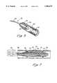
- FIG. 1is a partly cross-sectional, isometric view of one embodiment of the invention catheter
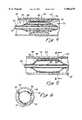
- FIG. 2is a cross-sectional view taken along line 2--2 of FIG. 1;
- FIG. 3is a perspective, schematic, sectional view of a portion of another embodiment of the invention illustrating the catheter positioned within a body conduit;
- FIG. 4is a sectional, side view of the embodiment of FIG. 3 in a deflated state
- FIG. 5is a sectional side view of the embodiment of FIG. 3 in an inflated state
- FIG. 6is a cross-sectional view along line 6--6 of FIG. 5;
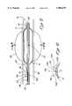
- FIG. 7is a sectional, elevational view of another embodiment of the invention.
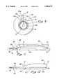
- FIG. 8is an axial cross-sectional view of a further embodiment of the invention illustrating the catheter disposed in the urethra in proximity to the prostate gland;
- FIG. 9is a radial cross-sectional view taken along lines 9--9 of FIG. 8;
- FIG. 10is an axial cross-sectional view similar to FIG. 9 illustrating the separation of cut tissue
- FIG. 11is an axial cross-section view of a further embodiment of the invention including finger tab means for advancing the cutting element into proximity with the tissue;
- FIG. 12is an axial cross-sectional view of a further embodiment of the invention wherein the cutting element is fixed to the catheter at a location proximal to the distal end of the catheter.
- FIG. 1depicts a dilatation catheter assembly, generally designated 10, that may be used for dilating a body vessel or conduit, such as a ureter or urethra, to treat a blockage or other obstruction.
- the main elements of catheter assembly 10are: an adapter 11 that defines the proximal end 12 of the assembly 10 and a site for various ports to the assembly 10; a catheter body 13 having a triple lumen 14 (FIG. 2); an inflatable balloon or bladder member 15; a stiffening guide wire or stylet 16 that extends longitudinally within one of the three lumens 14 of the catheter body 13; and a cutting element or electrode 17, preferably a radiofrequency cutting element 17 activatable by a radiofrequency power source 21.
- the electrosurgical cutting element 17is in the nature of a wire which extends generally parallel to the longitudinally.extending inflatable bladder 15.
- the bladder 15is inserted into a body conduit vessel or orifice to a location where a surgical cut is required.
- the bladder 15is then inflated (an inextensible bladder is generally used) with radiofrequency current being passed through the cutting element 17. This leads to the wire being moved outwardly and incising adjacent tissue in that direction.
- the material used for the wirecan be any of the materials currently used for electrosurgical cutting.
- the wirecan be made of stainless steel or tungsten.
- one of the three lumens 14serves as an inflation/deflation passageway 18
- a second lumencarries the guidewire or stylet 16 and serves as a drainage/infusion passageway
- a third lumencarries the cutting element 17.
- a sheath surrounding the cutting element 17can be provided with a slit facing away from the bladder 15.
- the inflatable balloon or bladder member 15is preferably of the inextensible or constant volume variety, that is it can, when expanded, assume only a specific size and shape.
- the balloon member 15cannot extend or bulge longitudinally within the body conduit beyond its predetermined diameter or length. Since a nondistensible balloon member 15 cannot extend longitudinally, as can elastic or elastomeric balloons, it must exert the force caused by inflation of the balloon member 15 radially against an enclosing body conduit or the like.
- an elastic or elastomeric balloonis expanded within a body conduit which has one portion particularly narrowed and particularly resistant to expansion, the balloon will simply elongate rather than acting radially outwardly against the constriction.
- a radiofrequency cutting element 17it is preferred to utilize a radiofrequency cutting element 17 for a number of reasons.
- a radiofrequency cutting element 17will not perform any cutting unless and until it is activated by passing a radiofrequency current through it.
- accidental cutscannot be made away from the area where cutting is desired.
- cuttingcan be very sharply defined leading to a clean incision without tearing.
- This radiofrequency cutting or cauterizing techniquecan, thus, provide significant advantages over the use of prior art cutters in an apparatus of the nature disclosed herein.
- the balloon member 15generally extends longitudinally along the body conduit and is generally symmetrically placed and expandable therein. In this manner, as the balloon member 15 is expanded, it exerts a substantially equal tangential tension upon the tissue defining the body conduit. This results in a very clean incision which extends generally parallel to the balloon member 15. In this manner the incision can be positioned longitudinally along the body cavity rather than at an axial angle as might be the case if the tangential tension in the body conduit were not substantially uniform.
- the cutting element 17is a radiofrequency cutting element and is disposed parallel to the bladder member 15.
- This bladder member 15extends longitudinally along the body conduit, is constructed of an inextensible non-elastic, non-elastomeric material and is symmetrically placed within the body cavity so that on expansion it exerts a substantially uniform tangential tension upon the tissue defining the body cavity.
- the adapter 11serves as a site for a bladder inflation/deflation port 19 that is attached to a source of inflation medium (not shown) for inflating the bladder member 15, or to a suction source (not shown) for deflating the bladder member 15.
- Port 19has a valve 20 for regulating the inflation medium or suction, as the case may be.
- Port 19connects into the proximal end of an inflation/deflation passageway 18 that extends from the port 19 to the bladder member 15.
- the adapter 11also serves as a site for the drainage tube inlet/outlet port 22 and a cutting element port 23.
- the drainage port 22is connected to the proximal end of the lumen that carries the guide wire or stylet 16.
- the drainage port 22may serve as a site for removing fluid from the lumen or as a site for infusing fluid into the lumen.
- the distal end of the catheter bodyhas a series of drain holes 24 to facilitate flushing the lumen with fluid or voiding the bladder member 15.
- a "banana plug” cutting element connector 25is affixed to the end of the cutting element port.
- the cutting element 17extends from the connector 25 through the lumen of the catheter body 13, exits therefrom via an aperture 26, and continues along the exterior of the bladder member 15.
- the cutting element 17can consist of a thin wire which has an external incising edge that faces outwardly from the bladder member 15.
- the cutting element 17may be a sharp edge, beam, or, more preferable, a radiofrequency cutting or cauterizing element 17.
- the element 17 and bladder member 15are constructed such that the cutting element 17 is carried on the exterior of the bladder member 15 (at least when the bladder member is inflated) but is not capable of incising the bladder member 15.
- the portion of the exterior of the bladder member 15 that is exposed to the cutting element 17may carry a protective cover (not shown) to further guard against the bladder member 15 being incised by the cutting element 17.
- the cutting element 17may be carried at a predetermined spacing from the bladder surface or directly on the surface. When carried on the surface the cutting element 17 may be an integral part of the surface or may be attached to the surface. In a preferred embodiment, the cutting element 17 is manually extendable or retractable via the connector 25 into and out of the catheter body 13.
- the distal end of the assembly 10includes a coudet tip 27.
- the assembly 10may optionally include another lumen and "Foley" type balloon (not shown) distally of the dilatation bladder member 15 to anchor the catheter in the bladder neck of the human body and thereby facilitate correct positioning of the dilatation bladder member 15. This has the further advantage of minimizing the possibility of migration and displacement of the assembly 10.
- One or more of the catheter assembly componentsmay be made of radiopaque materials to facilitate the visualization of the assembly 10 by the physician during placement of the assembly 10 in the body vessel/conduit.
- the typical surgical procedure in which the catheter assembly 10 is employedinvolves the following steps. Normally a cytoscope is first inserted into the vessel/conduit/orifice to be dilated. Calibration devices may be inserted through the cytoscope to facilitate measuring the extent of the vessel/conduit/orifice being dilated. The dilatation catheter of FIG. 1 is then inserted to the desired depth in the vessel/conduit and positioned using fluoroscopic and/or x-ray techniques.
- the bladder member 15is inflated. Such inflation causes the cutting element 17 to move radially outwardly as the bladder surface expands radially until the cutting element 17 contacts the surrounding tissue.
- tissueis intended to include, without limitation, normal tissue, neoplastic tissue (tumors) or an obstruction such as plaque.
- the bladder member 15is nondistensible.
- the inflated bladder member 15provides the additional benefit of acting as a tamponade to reduce bleeding.
- the power through the radiofrequency cutting element 17is discontinued.
- the bladder member 15can be deflated by operation of the inflation/deflation port valve 20. Deflation of the bladder member 15 permits a simultaneously radial retraction of the cutting element 17 out of contact with the tissue.
- the cutting element 17may be retracted via the connector 25. If desired, the cutting element 17 may be retracted prior to complete deflation of the bladder member 15 and/or the bladder member 15 reinflated and left in place to act as a tampon. Alternatively, the catheter can be withdrawn from the vessel/conduit altogether.
- FIGS. 3-6depict another dilatation catheter assembly of the invention, designated generally by the reference numeral 29. Only the distal end of the assembly 29 is shown.
- the adapter(s), as well as the various inflation/deflation portsare not shown for convenience.
- the distal end of the catheteris defined by a closed end catheter tube 32 which carries an inflatable, preferably inextensible, bladder member 33 on its exterior.
- the lumen 34 of the tube 32is connected to the source of inflation fluid pressure/suction, as the case may be.
- the tube 32has a radial aperture 35 that opens into the lumen 36 of the bladder member 33.
- a pair of expandable ring-shaped members 37, 38extend around the exterior of the bladder member 33 near the distal and proximal ends thereof.
- One or more cutting elements 39are affixed between the rings so that they extend longitudinally and outwardly therefrom.
- FIG. 3 (in solid line) and FIG. 4show both the assembly 29 in its deflated state positioned within a vessel 42 partially occluded by an obstruction 43.
- pressurized fluidis passed through catheter tube lumen 34 and aperture 35 into the bladder lumen. Inflation of the bladder member 33 in turn causes the ring members 37, 38 to expand and move the cutting element(s) 39 radially outward.
- FIGS. 3 (phantom line), 5, and 6show the bladder member 33 in an inflated state with the cutting element 39 incising the obstruction.
- FIG. 7shows yet another dilatation catheter assembly, generally designated 46, of the invention.
- the assembly 46is shown in its deflated state.
- This assembly 46is similar in structure to assembly 29 except that the assembly 46 is housed within a sheath or introducer 47 and a cauterizing element 48 is connected to the cutting element 39.
- the sheathpermits the assembly 46 to be introduced into the vessel in an unexposed manner, ejected from the end thereof for use, and retracted back into the sheath 47 after use. The ejection and retraction may be achieved by relative longitudinal movement of the sheath 47, assembly 46, or both.
- a heating element 49permits the cutting element (which in this instance must be made of a heat conducting material) to be heated to a temperature which allows the tissue to be both incised and cauterized.
- the heating elementis connected to a heat source/control, schematically shown at 49.
- the cutting element 39can be a radiofrequency cutting element and cauterization will result along with the cutting.
- a reduced power radiofrequency signalcan be passed through cutting element 39 to accomplish further cauterization.
- the heat source control 49would be replaced by a radiofrequency signal generator.
- this passage or body conduitmay include a urethra 50.
- the urethra 50is surrounded by a prostate gland 52 which has a relatively thick, inflexible outer layer of tissue.
- the interior tissue forming the prostate gland 52tends to expand or grow with age, and the relatively thick outer tissue forces this growth inwardly where it tends to restrict the passage formed by the urethra 50.
- the catheter 10(including at least a pair of lumens 14a and 14b) can be inserted into the urethra 50 with the balloon 15 positioned in a deflated state within the prostate 52.
- the electrosurgical cutting element 17is disposed in outlying relationship with respect to the balloon 15 between the balloon 15 and the wall of the urethra 50.
- the cutting element 17includes a first end 61 and a second end 63.
- the first end 61is fixed to the catheter at a point 65 which in this embodiment is located at the distal end of the catheter 10.
- the cutting element 17extends outwardly of the balloon 15, through the aperture 26 and into the lumen 14a of the catheter 10. Within the lumen 14a, the cutting element 17 is attached to one end of a spring 78 the other end of which is fixed to the catheter body 13. The cutting element 17 is energized with radiofrequency power which is transmitted through the spring 78 into the cutting element 17. From the forgoing description it is apparent that the cutting element 17 includes portions 69 which are disposed exteriorly of the catheter body 13, and portions 70 which are disposed interiorly of the catheter body 13.
- the balloon 15is inflated by introducing a fluid into the lumen 14b which then exits the lumen 14b through a port 54 beneath the balloon 15. As the fluid inflates the balloon 15, the cutting element 17 is carried outwardly against the force of the spring 78 into proximity with the wall of the urethra 50.
- the balloon 15is symmetrical about a longitudinal axis which is aligned with the longitudinal axis of the catheter 10. As the balloon 15 expands, it exerts a generally equal pressure against the wall of the urethra 50 thereby placing this tissue in tension.
- the electrosurgical element 17When the electrosurgical element 17 is activated by the radiofrequency signal, a current of high density is passed through the cells of the urethra 50 which are in close proximity to the element 17. By activating the cutting element 17 the cells are vaporized, incised, or otherwise cut along the element 17.
- FIG. 9a progression of points along the radial cut line 72 are designated 72a, 72b, and 72c.
- FIG. 10the tangential forces illustrated by the arrows 58 and 59 are shown to have separated the two portions of cut tissue at the point 72a and these points have moved outwardly in opposite directions as shown by the points 72a'.
- the radiofrequency electrical power delivered to the cutting element 17can be provided in different forms depending on the result desired. For example, a continuous low amplitude power can be provided to facilitate cutting of the tissue while a pulsed high amplitude power can be provided to enhance cauterization of the tissue. In practice, these different forms of power may be blended to provide for different ratios of cutting and cauterizing. Ultimately the radiofrequency power is completely discontinued to halt any further cutting or cauterizing of the tissue.
- the balloon 15can be deflated to permit the cutting element 17 to move radially away from the cut tissue into proximity with the catheter body 13.
- FIGS. 11 and 12differ from the foregoing description in that the catheter 10 is not provided with a balloon 15. Rather, the means for advancing the cutting element 17 into proximity with the tissue, comprises a finger tab 84.
- This tab 84engages the cutting element 17 preferably through a slot in the body 13 of the catheter. As the tab 84 is moved distally of the catheter 10, the cutting element 17 passes through the aperture 26 to increase the length of the exterior portions 69 relative to the interior portions 70. By increasing the length of the exterior portions 69, the cutting element 17 tends to move outwardly, radially into proximity with the urethra 50.
- each of the progressive positions of the exterior portions 69define a parabola. In other embodiments, this particular configuration may be ovoid.
- the element 17can be activated in the manner previously discussed.
- the cutting element i7can be withdrawn from proximity to the tissue into compliance with the catheter body 13. In the embodiments of FIGS. 11 and 12, this is accomplished by moving the finger tab 84 proximally thereby drawing the cutting element into the lumen 14a of the catheter 10. By moving the finger tab 84 proximally of the catheter 10, the cutting element 17 is drawn through the aperture 26 thereby decreasing the length of the exterior portions 69 relative to the interior portions 70.
- the cutting element 17includes the interior portions 70 which are disposed in the lumen 14a and the exterior portions 69 which are disposed outside of the catheter body 13. Either the balloon 15 or the finger tab 84 provides means for increasing the length of the exterior portions 69 so that the cutting element 17 is moved radially outwardly into contact with the tissue. In both cases, the cutting element 17 moves radially into proximity with the catheter body 13 when the radial force of the balloon or the distal force on the finger tab 84 are relieved. In both cases, the spring 78 provides a proximal tension on the cutting element 17 decreasing the length of the exterior portions 69 while increasing the length of the interior portions 70.
- the aperture 26is disposed proximally of the point 74.
- the aperture 26is disposed at the distal end of the catheter 10 so that the point 74 is disposed proximally of the aperture 26.
- the cutting element 17is bent back on itself through the aperture 26. Nevertheless, these embodiments function similarly in that the cutting element moves radially, outwardly as its interior portion 72 are advanced distally in the catheter 10.
Landscapes
- Health & Medical Sciences (AREA)
- Life Sciences & Earth Sciences (AREA)
- Surgery (AREA)
- Engineering & Computer Science (AREA)
- Heart & Thoracic Surgery (AREA)
- Animal Behavior & Ethology (AREA)
- Veterinary Medicine (AREA)
- Public Health (AREA)
- General Health & Medical Sciences (AREA)
- Biomedical Technology (AREA)
- Molecular Biology (AREA)
- Nuclear Medicine, Radiotherapy & Molecular Imaging (AREA)
- Medical Informatics (AREA)
- Physics & Mathematics (AREA)
- Vascular Medicine (AREA)
- Plasma & Fusion (AREA)
- Otolaryngology (AREA)
- Biophysics (AREA)
- Pulmonology (AREA)
- Child & Adolescent Psychology (AREA)
- Anesthesiology (AREA)
- Cardiology (AREA)
- Hematology (AREA)
- Orthopedic Medicine & Surgery (AREA)
- Surgical Instruments (AREA)
Abstract
Description
This application is a continuation of application Ser. No. 08/070,495, filed Jun. 2, 1993, now abandoned, which is a continuation of Ser. No. 07/647,472 filed Jan. 29, 1991, now abandoned, which is a CIP of Ser. No. 07/522,148 filed May 11, 1990, now abandoned, which is a CIP of Ser. No. 07/298,477 filed Jan. 18, 1989 now abandoned. The application is further related to application Ser. No. 08/347,838, now U.S. Pat. No. 5,628,746 which is a Continuation of application Ser. No. 07/873,712, now abandoned, which in turn is a Continuation-In-Part of application Ser. No. 07/522,148, now abandoned.
The present invention relates generally to the field of surgical devices and more specifically to electrosurgical devices adapted to incise body tissue.
In radiofrequency electrosurgical cutting a radiofrequency current is allowed to pass from an active cutting electrode through a patient's tissue and into a grounding pad or cable. The current cuts tissue at the active cutting electrode, the cutting rate being dependant on current density through the tissue in that area. With a low current density heat is generated but no cut is achieved. With a high current density fast cutting occurs.
Current density depends upon the voltage applied to the electrosurgical circuit and the series impedance or resistance to current flow of that circuit. Current density is also dependent upon the area the active cutting electrode presents to the patient's tissue. The smaller this area, the higher the current density. Since the area of the active electrode is fixed for a specific cutter, and the series impedance of the circuit is beyond the surgeon's control, the current density is typically adjusted by varying the voltage applied to the electrode. This adjustment is typically present on conventional electrosurgical generators.
The series impedance is dependent upon several factors which are outside the control of the surgeon. These factors may include the material and design of the active electrode, the type of tissue to be cut, and the location of the grounding pad relative to the cutting site. Generators used in this type of surgery have a wide range of power output to accommodate a variety of procedures and devices. For example, the generator can be adjusted to either cut tissue or to merely cauterize previously cut or torn tissue.
The objective in electrosurgical cutting is to heat the cells of the tissue so rapidly that they explode into steam leaving a cavity in the cell matrix. The heat is meant to be dissipated in the steam and not to dry out adjacent cells. When the electrode is moved and fresh tissue is contacted, new cells are exploded and the incision is made. The current utilized in electrosurgical cutting is in the radiofrequency range and operates by jumping across an air gap to the tissue. This is commonly referred to as sparking.
An explanation of electrosurgical cutting theory can be found in the FORCE 1 Instruction Manual published by Valleylab of Boulder, Colo., on Mar. 1, 1986.
An advantage of electrosurgical cutting, particularly if it is performed utilizing a cutting electrode as disclosed in application Ser. No. 07/522,254 filed May 11, 1990, now U.S. Pat. No. 5,080,660 is that overheating of adjacent tissue with accompanying desiccation and damage is limited or prevented. Thus, this procedure provides a clean cut without damage to adjacent tissue. A clean controlled cut is particularly desirable to assure that tearing does not occur in a direction away from the desired orientation of the cut.
Dilatation catheters are used to dilate body vessels, orifices and conduits such as an artery narrowed by atherosclerotic plaque or a urethra constricted by an enlarged prostate. These catheters basically consist of an elongate cannula having an inflatable non-extensible balloon or bladder at or near its distal end. A guide wire or other axial support means is often included to improve the torque control or "steerablilty" of the catheter.
The major advantage of using a dilatation catheter instead of conventional surgery is that it is less invasive. Nevertheless, the dilatation processes of the past can also result in significant trauma. As the elastomeric bladder expands, it exerts pressure on the surrounding tissue, causing the tissue to compress, deform and expand. The tissue, of course, has an inherent limit of deformability. When the dilation pressure causes the tissue to deform beyond that limit, the tissue tears apart, often to form a jagged wound. A principal object of the present invention is to provide a dilatation catheter that permits tissue to be stressed, even beyond its limit of deformability, without experiencing uncontrolled tearing and the undesirable conditions associated therewith.
U.S. Pat. No. 4,747,405 issued to Leckrone on May 31, 1988, U.S. Pat. No. 4,669,469, issued Jun. 2, 1987 to Gifford, III., et al., and PCT/US 86/02617 application of Leckrone, published Jun. 16, 1988, are each concerned with atherecotomy devices wherein a balloon is used to position an opening in a casing about an obstruction such as plaque. The balloon does not carry a cutting element to incise tissue but does carry means for disintegrating the plaque which is generally entrapped within a hole in the casing. The balloon basically positions the hole in the casing up against and about the plaque. Thus, the balloon is not symmetrically located within the blood vessel, an outward cutting element is not present, and the blood vessel is not torn by the dilation force.
U.S. Pat. No. 4,799,479, issued Jan. 24, 1989 to Spears, shows use of a balloon to open up an artery and then utilizes a laser, heated wire mesh, or the like, to heat up blood trapped between the media and the plaque so that dilation will be maintained and so that a smooth wall will result.
U.S. Pat. No. 4,273,128, issued Jun. 16, 1981 to Lary, teaches the use of a balloon with a knife blade, or a series of knife blades, longitudinally distally removed from the balloon.
Soviet Patent 599802 published in 1976 utilizes a balloon which is located within a tube. When the balloon is extended this forces a cutting element through a window in the tube to accomplish fenestration. Balloon pressure is not exerted against body tissue as the balloon is expanded within the tube.
German Patent 3,402,573 is concerned with a single lumen multi-purpose catheter having an extensible elastic balloon with a cutting facility for treatment of stenosis. This patent utilizes three balloons of equal size at the distal end of the catheter. Each elastomeric balloon carries small cutter elements which extend in the longitudinal direction and which are held in a trough made of hard rubber or plastic. Prior to use the cutters lie hidden in longitudinal slots of the relatively thick wall of the one-lumen catheter. Threads anchor the plate when the balloons are inflated thereby limiting the degree of penetration of adjacent plaque and possibly tissue.
U.S. Pat. No. 4,484,579, issued to Meno, et al. on Nov. 27, 1984, is concerned with a commissurotomy catheter which serves for separating fused heart valve leaflets. The device includes four balloons carried by a single catheter structure. In use the device fits through the valve with two balloons on each side of the valve. A nylon or similar string is attached between the pairs of balloons on each side of the valve. The balloons can be alternately expanded and contracted thereby causing the strings strung between each pair of balloons to saw or pulsate into fused portions of the heart valve leaflets and separate them. The actual cutting portion of the string is not carried on the exterior of the balloons.
The above-mentioned patents do not make use of an electrosurgical or radiofrequency cauterizing or cutting element. Nor do the above patents either suggest or show any advantages for utilizing an inextensible bladder or balloon, i.e., a balloon which is not elastomeric (or elastic) and which can be inflated to only a selected shape and volume. Furthermore, the above discussed patents are not concerned with a radially symmetrically, generally cylindrical in shape when expanded, balloon which extends longitudinally along a body passage and a cutting element which extends longitudinally along and generally parallel to the balloon, which balloon creates a substantially uniform tangential tension in tissue being cut, and which cutting element at the same time performs the necessary cutting whereby a clean longitudinally extending incision results and uncontrolled tearing of the tissue does not occur.
The present invention is directed to overcoming one or more of the problems as set forth above.
A catheter assembly is used to deploy a cutting element such as an electrosurgical cutter, into a body passage, such as a vessel, orifice or other body conduit. A dilatable balloon disposed at the distal end of the catheter provides means for moving the cutting element outwardly of the catheter toward the tissue to be cut. After the balloon has been dilated and the cutting element is disposed in proximity to the tissue, the element can be activated, for example with a radiofrequency signal, to cut the tissue. Then the signal can be reduced in magnitude to cauterize the cut tissue prior to deflating the balloon. Once the balloon is deflated and the cutting element retracted into proximity to the catheter, the lower profile of the catheter will permit withdrawal from the passage.
In accordance with an embodiment of the invention a dilatation catheter assembly comprises in combination: an elongated tubular body having a distal end carrying a radially dilatable inextensible elongate member adapted to be positioned longitudinally along a body conduit and to dilate in a radially symmetrical manner and exert pressure on surrounding body tissue to provide a substantially uniform tangential tension therein; means for dilating the dilatable member to a relatively constant inextensible volume and a cutting element carried on the exterior of the dilatable member that moves radially in concert with the exterior of the dilatable member and is adapted to incise said tissue, thereby reducing damage to said tissue from dilation forces.
In accordance with another embodiment of the invention a dilatation catheter assembly comprises, an elongated tubular body having a distal end carrying a radially dilatable member adapted to be positioned in a body conduit and to exert pressure on surrounding body tissue; means for dilating the dilatable member; and an electrosurgical cutting element carried on the exterior of the dilatable member that moves radially in concert with the exterior of the dilatable member and that is adapted to incise the tissue, thereby reducing damage to the tissue from dilation forces.
In another aspect of the invention, the catheter is particularly adapted for enlarging the diameter or other cross-sectional dimension of a body passage, such as a vessel orifice or other body conduit. A conduit of particular interest is the prostatic urethra which in the case of male patients is commonly restricted by the inward growth of the prostate gland which surrounds the urethra. Such restriction often inhibits urination resulting in the discomfort associated with frequency, urgency and control. Various attempts have been made to dilate the prostatic urethra but success has been considerably limited in terms of both efficacy and longevity.
Accordingly, another aspect of the invention is a method for dilating a body conduit, vessel or orifice comprising the steps of inserting thereinto a dilatation catheter assembly comprising an elongated tubular body having a distal end carrying a radially dilatable inextensible member adapted to be positioned in a body conduit and to dilate in a radially symmetrical manner and to exert pressure on surrounding body tissue to provide a substantially uniform tangential tension therein, and a cutting element carried on the exterior of the dilatable member; dilating the inextensible dilatable member to an extent that causes the tissue to be simultaneously stressed by the dilatable member and incised by the cutting member; radially contracting the dilatable member to cause the dilatable member and cutting element to disengage the tissue; and withdrawing the dilation catheter assembly from the conduit, vessel or orifice.
Still another aspect of the present invention is a method for dilating a body conduit, vessel or orifice. This method comprises inserting thereinto a dilation catheter assembly comprising an elongate tubular body having a distal end carrying a radially dilatable member adapted to dilate and exert pressure on surrounding body tissue and an electrosurgical cutting element carried on the exterior of the dilatable member; simultaneously dilating the dilatable member to an extent that causes the tissue to be stressed by the dilatable member and activating the electrosurgical cutting element such that the tissue is simultaneously stressed by the dilatable member and incised by the cutting element; discontinuing activation of the electrosurgical cutting element; radially contracting the dilatable member to cause the dilatable member and cutting element to disengage the tissue; and withdrawing the dilation catheter assembly from the conduit, vessel or orifice.
The invention will be better understood with reference to the drawings wherein like numbers denote like parts and wherein:
FIG. 1 is a partly cross-sectional, isometric view of one embodiment of the invention catheter;
FIG. 2 is a cross-sectional view taken along line 2--2 of FIG. 1;
FIG. 3 is a perspective, schematic, sectional view of a portion of another embodiment of the invention illustrating the catheter positioned within a body conduit;
FIG. 4 is a sectional, side view of the embodiment of FIG. 3 in a deflated state;
FIG. 5 is a sectional side view of the embodiment of FIG. 3 in an inflated state;
FIG. 6 is a cross-sectional view along line 6--6 of FIG. 5;
FIG. 7 is a sectional, elevational view of another embodiment of the invention;
FIG. 8 is an axial cross-sectional view of a further embodiment of the invention illustrating the catheter disposed in the urethra in proximity to the prostate gland;
FIG. 9 is a radial cross-sectional view taken along lines 9--9 of FIG. 8;
FIG. 10 is an axial cross-sectional view similar to FIG. 9 illustrating the separation of cut tissue;
FIG. 11 is an axial cross-section view of a further embodiment of the invention including finger tab means for advancing the cutting element into proximity with the tissue; and
FIG. 12 is an axial cross-sectional view of a further embodiment of the invention wherein the cutting element is fixed to the catheter at a location proximal to the distal end of the catheter.
FIG. 1 depicts a dilatation catheter assembly, generally designated 10, that may be used for dilating a body vessel or conduit, such as a ureter or urethra, to treat a blockage or other obstruction. The main elements ofcatheter assembly 10 are: an adapter 11 that defines the proximal end 12 of theassembly 10 and a site for various ports to theassembly 10; acatheter body 13 having a triple lumen 14 (FIG. 2); an inflatable balloon orbladder member 15; a stiffening guide wire orstylet 16 that extends longitudinally within one of the threelumens 14 of thecatheter body 13; and a cutting element orelectrode 17, preferably aradiofrequency cutting element 17 activatable by a radiofrequency power source 21. Theelectrosurgical cutting element 17 is in the nature of a wire which extends generally parallel to the longitudinally.extendinginflatable bladder 15.
In use, thebladder 15 is inserted into a body conduit vessel or orifice to a location where a surgical cut is required. Thebladder 15 is then inflated (an inextensible bladder is generally used) with radiofrequency current being passed through the cuttingelement 17. This leads to the wire being moved outwardly and incising adjacent tissue in that direction.
The material used for the wire can be any of the materials currently used for electrosurgical cutting. For example, the wire can be made of stainless steel or tungsten. As illustrated in FIG. 2 herein, one of the threelumens 14 serves as an inflation/deflation passageway 18, a second lumen carries the guidewire orstylet 16 and serves as a drainage/infusion passageway, and a third lumen carries the cuttingelement 17. In accordance with the teachings in previously mentioned patent application Ser. No. 07/522,254, now U.S. Pat. No. 5,080,660, a sheath surrounding the cuttingelement 17 can be provided with a slit facing away from thebladder 15.
In accordance with the present invention the inflatable balloon orbladder member 15 is preferably of the inextensible or constant volume variety, that is it can, when expanded, assume only a specific size and shape. Thus, theballoon member 15 cannot extend or bulge longitudinally within the body conduit beyond its predetermined diameter or length. Since anondistensible balloon member 15 cannot extend longitudinally, as can elastic or elastomeric balloons, it must exert the force caused by inflation of theballoon member 15 radially against an enclosing body conduit or the like. In contrast, if an elastic or elastomeric balloon is expanded within a body conduit which has one portion particularly narrowed and particularly resistant to expansion, the balloon will simply elongate rather than acting radially outwardly against the constriction.
In accordance with the present invention it is preferred to utilize aradiofrequency cutting element 17 for a number of reasons. One reason is that aradiofrequency cutting element 17 will not perform any cutting unless and until it is activated by passing a radiofrequency current through it. As a result, accidental cuts cannot be made away from the area where cutting is desired. And second, with proper control, cutting can be very sharply defined leading to a clean incision without tearing. This radiofrequency cutting or cauterizing technique can, thus, provide significant advantages over the use of prior art cutters in an apparatus of the nature disclosed herein.
In accordance with the present invention theballoon member 15 generally extends longitudinally along the body conduit and is generally symmetrically placed and expandable therein. In this manner, as theballoon member 15 is expanded, it exerts a substantially equal tangential tension upon the tissue defining the body conduit. This results in a very clean incision which extends generally parallel to theballoon member 15. In this manner the incision can be positioned longitudinally along the body cavity rather than at an axial angle as might be the case if the tangential tension in the body conduit were not substantially uniform.
In accordance with the most preferred embodiment of the present invention, the cuttingelement 17 is a radiofrequency cutting element and is disposed parallel to thebladder member 15. Thisbladder member 15 extends longitudinally along the body conduit, is constructed of an inextensible non-elastic, non-elastomeric material and is symmetrically placed within the body cavity so that on expansion it exerts a substantially uniform tangential tension upon the tissue defining the body cavity. This configuration achieves many of the advantages associated with the present invention.
The adapter 11 serves as a site for a bladder inflation/deflation port 19 that is attached to a source of inflation medium (not shown) for inflating thebladder member 15, or to a suction source (not shown) for deflating thebladder member 15. Port 19 has avalve 20 for regulating the inflation medium or suction, as the case may be. Port 19 connects into the proximal end of an inflation/deflation passageway 18 that extends from the port 19 to thebladder member 15. The adapter 11 also serves as a site for the drainage tube inlet/outlet port 22 and acutting element port 23. The drainage port 22 is connected to the proximal end of the lumen that carries the guide wire orstylet 16. The drainage port 22 may serve as a site for removing fluid from the lumen or as a site for infusing fluid into the lumen.
The distal end of the catheter body has a series of drain holes 24 to facilitate flushing the lumen with fluid or voiding thebladder member 15. A "banana plug" cuttingelement connector 25 is affixed to the end of the cutting element port. The cuttingelement 17 extends from theconnector 25 through the lumen of thecatheter body 13, exits therefrom via anaperture 26, and continues along the exterior of thebladder member 15.
The cuttingelement 17 can consist of a thin wire which has an external incising edge that faces outwardly from thebladder member 15. Alternatively, the cuttingelement 17 may be a sharp edge, beam, or, more preferable, a radiofrequency cutting or cauterizingelement 17. Theelement 17 andbladder member 15 are constructed such that the cuttingelement 17 is carried on the exterior of the bladder member 15 (at least when the bladder member is inflated) but is not capable of incising thebladder member 15.
If desired, the portion of the exterior of thebladder member 15 that is exposed to the cuttingelement 17 may carry a protective cover (not shown) to further guard against thebladder member 15 being incised by the cuttingelement 17. The cuttingelement 17 may be carried at a predetermined spacing from the bladder surface or directly on the surface. When carried on the surface the cuttingelement 17 may be an integral part of the surface or may be attached to the surface. In a preferred embodiment, the cuttingelement 17 is manually extendable or retractable via theconnector 25 into and out of thecatheter body 13.
For use in urethral dilatation the distal end of theassembly 10 includes acoudet tip 27. Such structure may not be necessary or desirable for dilating other conduit/orifices. For urethral dilation, theassembly 10 may optionally include another lumen and "Foley" type balloon (not shown) distally of thedilatation bladder member 15 to anchor the catheter in the bladder neck of the human body and thereby facilitate correct positioning of thedilatation bladder member 15. This has the further advantage of minimizing the possibility of migration and displacement of theassembly 10. One or more of the catheter assembly components may be made of radiopaque materials to facilitate the visualization of theassembly 10 by the physician during placement of theassembly 10 in the body vessel/conduit.
The typical surgical procedure in which thecatheter assembly 10 is employed, involves the following steps. Normally a cytoscope is first inserted into the vessel/conduit/orifice to be dilated. Calibration devices may be inserted through the cytoscope to facilitate measuring the extent of the vessel/conduit/orifice being dilated. The dilatation catheter of FIG. 1 is then inserted to the desired depth in the vessel/conduit and positioned using fluoroscopic and/or x-ray techniques.
Once in position, thebladder member 15 is inflated. Such inflation causes the cuttingelement 17 to move radially outwardly as the bladder surface expands radially until the cuttingelement 17 contacts the surrounding tissue. As used herein the term "tissue" is intended to include, without limitation, normal tissue, neoplastic tissue (tumors) or an obstruction such as plaque. In accordance with a preferred embodiment of the invention thebladder member 15 is nondistensible.
Continued radial expansion of thebladder member 15 positions the cuttingelement 17 and causes thebladder member 15 to exert pressure on the tissue thereby subjecting the tissue to a substantially uniform tangential tension. Then a radiofrequency current can be passed through the cuttingelement 17.
This combined cutting and dilating action results in the tissue being expanded without being torn due to a buildup of excess stresses within the tissue. Instead, the tissue is cut in a clean, concentrated, generally longitudinal fashion by the cuttingelement 17 and the dilatation does not uncontrollably tear the tissue and cause excessive trauma and bleeding. Theinflated bladder member 15 provides the additional benefit of acting as a tamponade to reduce bleeding.
After the vessel/conduit/orifice tissue is incised and dilated, and the blockage/obstruction is relieved, the power through theradiofrequency cutting element 17 is discontinued. Then thebladder member 15 can be deflated by operation of the inflation/deflation port valve 20. Deflation of thebladder member 15 permits a simultaneously radial retraction of the cuttingelement 17 out of contact with the tissue. As thebladder member 15 is deflated the cuttingelement 17 may be retracted via theconnector 25. If desired, the cuttingelement 17 may be retracted prior to complete deflation of thebladder member 15 and/or thebladder member 15 reinflated and left in place to act as a tampon. Alternatively, the catheter can be withdrawn from the vessel/conduit altogether.
FIGS. 3-6 depict another dilatation catheter assembly of the invention, designated generally by thereference numeral 29. Only the distal end of theassembly 29 is shown. The adapter(s), as well as the various inflation/deflation ports are not shown for convenience. The distal end of the catheter is defined by a closedend catheter tube 32 which carries an inflatable, preferably inextensible,bladder member 33 on its exterior. Thelumen 34 of thetube 32 is connected to the source of inflation fluid pressure/suction, as the case may be. Thetube 32 has aradial aperture 35 that opens into thelumen 36 of thebladder member 33. A pair of expandable ring-shapedmembers bladder member 33 near the distal and proximal ends thereof. One or morecutting elements 39 are affixed between the rings so that they extend longitudinally and outwardly therefrom.
FIG. 3 (in solid line) and FIG. 4 show both theassembly 29 in its deflated state positioned within avessel 42 partially occluded by anobstruction 43. In order to inflate thebladder member 33, pressurized fluid is passed throughcatheter tube lumen 34 andaperture 35 into the bladder lumen. Inflation of thebladder member 33 in turn causes thering members bladder member 33 in an inflated state with the cuttingelement 39 incising the obstruction.
FIG. 7 shows yet another dilatation catheter assembly, generally designated 46, of the invention. Theassembly 46 is shown in its deflated state. Thisassembly 46 is similar in structure toassembly 29 except that theassembly 46 is housed within a sheath orintroducer 47 and acauterizing element 48 is connected to the cuttingelement 39. The sheath permits theassembly 46 to be introduced into the vessel in an unexposed manner, ejected from the end thereof for use, and retracted back into thesheath 47 after use. The ejection and retraction may be achieved by relative longitudinal movement of thesheath 47,assembly 46, or both.
Aheating element 49 permits the cutting element (which in this instance must be made of a heat conducting material) to be heated to a temperature which allows the tissue to be both incised and cauterized. The heating element is connected to a heat source/control, schematically shown at 49. As an alternative the cuttingelement 39 can be a radiofrequency cutting element and cauterization will result along with the cutting. Also, following cutting a reduced power radiofrequency signal can be passed through cuttingelement 39 to accomplish further cauterization. In such an embodiment, theheat source control 49 would be replaced by a radiofrequency signal generator.
The catheter assemblies associated with the present invention are of particular advantage when used to enlarge a body passage such as a vessel, or orifice, or other body conduit. As illustrated in FIG. 8, this passage or body conduit may include aurethra 50. In the case of a male patient, theurethra 50 is surrounded by aprostate gland 52 which has a relatively thick, inflexible outer layer of tissue. The interior tissue forming theprostate gland 52 tends to expand or grow with age, and the relatively thick outer tissue forces this growth inwardly where it tends to restrict the passage formed by theurethra 50.
In a procedure for enlarging theprostatic urethra 50, the catheter 10 (including at least a pair oflumens 14a and 14b) can be inserted into the urethra 50 with theballoon 15 positioned in a deflated state within theprostate 52. In this particular catheter illustrated in FIG. 8, the electrosurgical cuttingelement 17 is disposed in outlying relationship with respect to theballoon 15 between theballoon 15 and the wall of theurethra 50. The cuttingelement 17 includes afirst end 61 and asecond end 63. Thefirst end 61 is fixed to the catheter at apoint 65 which in this embodiment is located at the distal end of thecatheter 10. From thispoint 65, the cuttingelement 17 extends outwardly of theballoon 15, through theaperture 26 and into thelumen 14a of thecatheter 10. Within thelumen 14a, the cuttingelement 17 is attached to one end of aspring 78 the other end of which is fixed to thecatheter body 13. The cuttingelement 17 is energized with radiofrequency power which is transmitted through thespring 78 into the cuttingelement 17. From the forgoing description it is apparent that the cuttingelement 17 includesportions 69 which are disposed exteriorly of thecatheter body 13, andportions 70 which are disposed interiorly of thecatheter body 13.
In accordance with a preferred method theballoon 15 is inflated by introducing a fluid into the lumen 14b which then exits the lumen 14b through aport 54 beneath theballoon 15. As the fluid inflates theballoon 15, the cuttingelement 17 is carried outwardly against the force of thespring 78 into proximity with the wall of theurethra 50.
In a preferred embodiment theballoon 15 is symmetrical about a longitudinal axis which is aligned with the longitudinal axis of thecatheter 10. As theballoon 15 expands, it exerts a generally equal pressure against the wall of the urethra 50 thereby placing this tissue in tension.
When theelectrosurgical element 17 is activated by the radiofrequency signal, a current of high density is passed through the cells of the urethra 50 which are in close proximity to theelement 17. By activating the cuttingelement 17 the cells are vaporized, incised, or otherwise cut along theelement 17.
The tension in these cells tends to create forces which extend tangentially of theballoon 15 as shown byarrows urethra 50 is increased. As theballoon 15 is further inflated, new uncut tissue is brought into proximity to the cuttingelement 17 which continues to cut the tissue along a line, such as the dottedline 72 which extends generally radially of thecatheter 10.
In FIG. 9, a progression of points along theradial cut line 72 are designated 72a, 72b, and 72c. In FIG. 10 the tangential forces illustrated by thearrows point 72a and these points have moved outwardly in opposite directions as shown by thepoints 72a'.
As the cutting progresses, it may be advantageous to further inflate theballoon 15 in order to maintain the pressure and tangential forces required for separating the cut tissue.
The radiofrequency electrical power delivered to the cuttingelement 17 can be provided in different forms depending on the result desired. For example, a continuous low amplitude power can be provided to facilitate cutting of the tissue while a pulsed high amplitude power can be provided to enhance cauterization of the tissue. In practice, these different forms of power may be blended to provide for different ratios of cutting and cauterizing. Ultimately the radiofrequency power is completely discontinued to halt any further cutting or cauterizing of the tissue.
Even after cutting and cauterizing have been stopped, it may be desirable to maintain or even increase the pressure in theballoon 15 in order to provide a tamponade for inhibiting bleeding in the region of the cut cells. Ultimately the balloon can be deflated to permit the cuttingelement 17 to move radially away from the cut tissue into proximity with thecatheter body 13.
The embodiments of FIGS. 11 and 12 differ from the foregoing description in that thecatheter 10 is not provided with aballoon 15. Rather, the means for advancing the cuttingelement 17 into proximity with the tissue, comprises afinger tab 84. Thistab 84 engages the cuttingelement 17 preferably through a slot in thebody 13 of the catheter. As thetab 84 is moved distally of thecatheter 10, the cuttingelement 17 passes through theaperture 26 to increase the length of theexterior portions 69 relative to theinterior portions 70. By increasing the length of theexterior portions 69, the cuttingelement 17 tends to move outwardly, radially into proximity with theurethra 50.
As thetab 84 moves distally of thecatheter 10, theexterior portions 69 of the cuttingelement 17 assume progressive positions having a particular configuration. In most cases, this particular configuration will at least be arcuate. In FIG. 11 wherein theaperature 26 is disposed proximally of thisexterior portion 69, the particular configuration tends to be parabolic. Thus each of the progressive positions of theexterior portions 69 define a parabola. In other embodiments, this particular configuration may be ovoid.
In FIG. 12, wherein theaperature 26 is disposed distally of theexterior portions 69, the particular configuration tends to take the shape of one side of a heart. Each of these configurations may have a particular advantage in the context of a particular operative procedure.
After thecatheter 10 has been positioned, and the cuttingelement 17 has been operationally deployed into contact with the tissue, theelement 17 can be activated in the manner previously discussed. When the tissue has been cut thereby enlarging the circumferential dimension of the passage or cavity, the cutting element i7 can be withdrawn from proximity to the tissue into compliance with thecatheter body 13. In the embodiments of FIGS. 11 and 12, this is accomplished by moving thefinger tab 84 proximally thereby drawing the cutting element into thelumen 14a of thecatheter 10. By moving thefinger tab 84 proximally of thecatheter 10, the cuttingelement 17 is drawn through theaperture 26 thereby decreasing the length of theexterior portions 69 relative to theinterior portions 70.
In all of these preferred embodiments, both those with theballoon 15 and those with thefinger tab 84, the cuttingelement 17 includes theinterior portions 70 which are disposed in thelumen 14a and theexterior portions 69 which are disposed outside of thecatheter body 13. Either theballoon 15 or thefinger tab 84 provides means for increasing the length of theexterior portions 69 so that the cuttingelement 17 is moved radially outwardly into contact with the tissue. In both cases, the cuttingelement 17 moves radially into proximity with thecatheter body 13 when the radial force of the balloon or the distal force on thefinger tab 84 are relieved. In both cases, thespring 78 provides a proximal tension on the cuttingelement 17 decreasing the length of theexterior portions 69 while increasing the length of theinterior portions 70.
In the embodiment of FIG. 8, theaperture 26 is disposed proximally of the point 74. However, in the embodiment of FIG. 12, theaperture 26 is disposed at the distal end of thecatheter 10 so that the point 74 is disposed proximally of theaperture 26. In this embodiment, the cuttingelement 17 is bent back on itself through theaperture 26. Nevertheless, these embodiments function similarly in that the cutting element moves radially, outwardly as itsinterior portion 72 are advanced distally in thecatheter 10.
While the invention has been described in connection with specific embodiments thereof, it will be understood that it is capable of further modification, and this application is intended to cover any variation, uses, or adaptions of the invention following, in general, the principles of the invention and including such departures from the present disclosure as come within known or customary practice in the art to which the invention pertains and as may be applied to the essential features hereinbefore set forth, and as fall within the scope of the invention and the limits of the appended claims.
Claims (64)
1. A method for dilating a non-vascular body conduit, comprising:
inserting into the non-vascular conduit a dilation catheter assembly comprising an elongate tubular body having a distal end carrying a radially dilatable member adapted to be positioned in the conduit and to exert pressure on surrounding body tissue to provide a substantially uniform tangential tension in the tissue, and a cutting element carried on the dilatable member;
dilating the dilatable member to simultaneously stress the tissue and engage the tissue with the cutting element;
electrically activating the cutting element;
incising the stressed tissue with the cutting element;
radially contracting the dilatable member to cause the dilatable member and cutting element to disengage the tissue; and
withdrawing the dilation catheter assembly from the conduit.
2. The method of claim 1 wherein the cutting element is a radiofrequency cutter and the method further including the steps of:
passing a radiofrequency current through the cutter during the dilating of the dilatable member; and,
discontinuing the radiofrequency current during the radial contracting of the dilatable member.
3. The method of claim 2 wherein the step of passing the radiofrequency current includes the steps of:
introducing a radiofrequency signal into the cutting element to cut the tissue; and
reducing the power of the radiofrequency signal to cauterize the cut tissue.
4. The method of claim 1 including the step of cauterizing the tissue with the cutting element.
5. A method for enlarging the diameter of a ureteral passage defined by body tissue, comprising:
inserting into the ureteral passage a catheter having a catheter body, a cutting element in the form of an elongate wire, and means for advancing the cutting element laterally of the catheter body;
advancing the cutting element into proximity with the tissue; and
electrically activating the cutting element to cut the tissue and enlarge the diameter of the ureteral passage.
6. The method recited in claim 5 wherein after the activating step, the method further comprises the steps of stretching the tissue defining the ureteral passage in order to enlarge the ureteral passage.
7. The method recited in claim 6 further comprising the step of pressurizing the cut tissue to inhibit bleeding of the tissue.
8. The method recited in claim 7 further comprising the steps of:
deactivating the cutting element;
retracting the cutting element into proximity to the catheter body; and withdrawing the catheter from the ureteral passage.
9. The method recited in claim 7 wherein during the providing step, the catheter is provided with an inflatable balloon and during at least one of the advancing, stretching, and pressurizing steps, the method further comprises the step of inflating the balloon.
10. The method recited in claim 5 wherein after the activating step, the method further comprises the step of advancing the cutting element into proximity with previously uncut tissue.
11. The method recited in claim 5 wherein during the activating step the tissue is cut into two portions and the method further comprises the step of separating the two cut portions of the tissue to expose uncut tissue to the cutting element.
12. The method recited in claim 5 wherein prior to the activation step the method further comprises the step of stretching the tissue in proximity to the cutting element.
13. A method for enlarging the diameter of a passage defined by body tissue and having a longitudinal axis, comprising:
inserting into the passage a catheter having an inflatable balloon and a cutting element in the form of an electrosurgical wire disposed in contact with the outer surface of the balloon;
inflating the balloon to move the cutting element into proximity with the body tissue;
activating electrically the cutting element to cut the body tissue in only a substantially axial direction;
deflating the balloon to withdraw the cutting element from proximity with the body tissue; and
withdrawing the catheter from the passage.
14. The method recited in claim 13 wherein prior to the deflating step the method further comprises the step of advancing the cutting element into proximity with previously uncut tissue.
15. The method recited in claim 14 further comprising the step of repeating the activating step.
16. The method recited in claim 13 wherein prior to the activating step the method further comprises the step of stretching the body tissue.
17. The method recited in claim 13 wherein subsequent to the activating step the method further comprises the step of pressurizing the cut tissue to inhibit bleeding.
18. The method recited in claim 13 wherein prior to the deflating step the method further comprises the step of deactivating the cutting element to discontinue cutting the body tissue.
19. The method recited in claim 13 wherein during the deflating step the method further comprises the step of automatically retracting the cutting element from proximity with the body tissue.
20. A method for enlarging the diameter of a passage defined by body tissue, comprising:
inserting into the passage a catheter having a wall defining a lumen extending between a distal end of the catheter and a proximal end of the catheter, and an electrosurgical wire having first portions disposed exteriorly of the catheter and second portions disposed interiorly of the catheter, the wire including a first end fixed to the catheter and a second end movable within the lumen of the catheter to vary the length of the first portions of the wire relative to the length of the second portions of the wire;
moving the second end of the wire distally within the lumen of the catheter to increase the length of the first portions of the wire and thereby move the first portions laterally of the catheter wall into proximity with the tissue;
activating the electrosurgical wire to cut the tissue in proximity to the wire; and
moving the second end of the wire proximally within the lumen of the catheter to decrease the length of the first portions of the wire and thereby move the first portions laterally of the catheter wall into proximity with the catheter wall.
21. The method recited in claim 20 further comprising the step of providing the catheter with a balloon disposed between the wire and the catheter wall, the balloon being inflatable to move the wire into proximity with the body tissue.
22. The method recited in claim 21 wherein the first moving step includes the step of inflating the balloon through the lumen of the catheter wall.
23. The method recited in claim 22 wherein the second moving step includes the step of deflating the balloon through the lumen of the catheter wall.
24. The method recited in claim 21 further comprising the step of attaching the first end of the wire to the catheter distally of the balloon.
25. The method recited in claim 21 further comprising the step of attaching the first end of the wire to the catheter wall proximally of the balloon.
26. A catheter assembly adapted for use in the urinary system and comprising in combination:
an elongate tubular body having a lumen and an axis extending to a distal end;
a dilatable member having an outwardly facing exterior surface and being disposed to surround the distal end of the tubular body in communication with the lumen of the tubular body, the dilatable member being adapted for disposition in the urinary system and being dilatable in response to fluid pressure in the lumen of the tubular body to exert pressure on surrounding body tissue in order to create tension in the body tissue;
cutting means disposed substantially only axially to extend in close contacting relationship with the exterior surface of the dilatable member and having characteristics for being moved into proximity with the surrounding tissue when the dilatable member is dilated, for incising said tissue axially along the tubular body to relieve the tension in the body tissue and to enlarge the body conduit; and
means for electrically energizing the cutting means to permit incision and cauterization of the tissue.
27. The assembly of claim 26 wherein the dilatable member is an inflatable bladder that is adapted to be inflated to a predetermined volume and shape.
28. The assembly of claim 27 wherein the cutting means is permanently affixed to the inflatable bladder.
29. The catheter assembly recited in claim 27 wherein the inflatable bladder is symmetrically disposed around the tubular body and the dilation of the inflatable bladder exerts an uniform tangential tension on the surrounding tissue.
30. The assembly of claim 26 wherein the cutting means is an integral component of the dilatable member.
31. The assembly of claim 26 wherein the cutting means comprises a thin wire.
32. The assembly of claim 26 including an open ended sheath from which the tubular body may be ejected for use and into which the tubular body may be retracted after use.
33. The catheter assembly recited in claim 26 wherein the cutting means comprises a radiofrequency electrosurgical cutting element.
34. A catheter adapted to cut tissue, comprising:
a tube having a longitudinal axis extending between a distal end and a proximal end of the catheter;
cutting means disposed generally at the distal end of the tube for cutting the tissue, the cutting means including only a single axially oriented wire, having no point of intersection with any second cutting wire, the single wire having portions movable radially of the axis of the catheter;
means for moving the cutting means portions radially into close proximity to the tissue to be cut;
means for electrically activating the cutting means to cut the tissue in proximity to the cutting means; and
means for exposing previously uncut tissue to the cutting means.
35. The catheter recited in claim 34 wherein the moving means comprises a balloon inflatable through the tube and having portions disposed in a fixed relationship with the tube of the catheter.
36. The catheter recited in claim 35 wherein the balloon has a longitudinal axis generally aligned with the longitudinal axis of the tube.
37. The catheter recited in claim 35 wherein the balloon has an outer surface and the wire is movable radially with the outer surface when the balloon is inflated.
38. The catheter recited in claim 34 wherein the exposing means includes means operable with the tube stationary relative to the tissue for applying a force to the tissue to separate the cut tissue and thereby move the uncut tissue into proximity with the cutting means.
39. The catheter recited in claim 38 wherein the exposing means includes a balloon inflatable through the tube and having a curved outer surface, and the force is applied to the tissue tangentially of the outer surface of the balloon.
40. The catheter recited in claim 34 further comprising tamponade means for applying pressure to the cut tissue.
41. The catheter recited in claim 34 wherein the activating means comprises means for directing an electrosurgical signal through the wire, the signal having a magnitude sufficient to cut the tissue.
42. A catheter adapted to cut tissue, comprising:
a tube having a longitudinal axis extending between a distal end and a proximal end of the catheter;
cutting means disposed generally at the distal end of the tube for cutting the tissue, the cutting means including only a single axially oriented wire having no point of intersection with any second cutting wire, the single wire having portions movable radially of the axis of the catheter;
means for moving the cutting means portions radially into close proximity to the tissue to be cut, comprising a balloon inflatable through the tube and having portions disposed in a fixed relationship with the tube of the catheter, the balloon having an outer surface and the wire being movable radially with the outer surface when the balloon is inflated, the balloon having first and second ends fixed to the tube, and the wire having a first end fixed relative to the first end of the balloon and a second end movable relative to the second end of the balloon; and
means for activating the cutting means to cut the tissue in proximity to the cutting means; and means for exposing previously uncut tissue to the cutting means.
43. The catheter recited in claim 42 wherein the wire has a proximal end and a distal end and the first end of the wire is the distal end of the wire.
44. Apparatus for cutting a non-vascular body conduit comprising:
a supporting structure having an outer surface;
an electrosurgical cutter in the form of a wire having first portions disposed in a fixed relationship with the supporting structure and second portions disposed outwardly of the outer surface in a movable relationship with the supporting structure;
means disposed between the supporting structure and the second portions of the cutter for moving the second portions of the cutter into proximity with the tissue to be cut; and
means for electrically activating the cutter to cut the non-vascular body conduit.
45. The apparatus recited in claim 44 wherein the supporting structure defines a lumen and the moving means comprises a balloon inflatable through the lumen and having first portions fixed to the catheter and second portions movable relative to the catheter, the second portions of the balloon being disposed between the catheter and the second portions of the cutter to move the cutter into proximity with the non-vascular body conduit when the balloon is inflated.
46. Tissue cutting apparatus, comprising:
a supporting structure including portions defining a lumen and having an outer surface;
an electrosurgical cutter in the form of a wire having first portions disposed in a fixed relationship with the supporting structure, and second portions disposed outwardly of the outer surface in a movable relationship with the supporting structure;
means disposed between the supporting structure and the second portions of the cutter for moving the second portions of the cutter into proximity with the tissue to be cut, the moving means comprising a balloon inflatable through the lumen of the supporting structure;
means for electrically activating the cutter to cut the tissue; and
means disposed between the cutter and the balloon for directing energy from the electrical cutter away from the balloon and toward the tissue.
47. The tissue cutting apparatus recited in claim 46 wherein the supporting structure is a catheter having a proximal end and a distal end, and the electrosurgical cutter is disposed near the distal end of the catheter.
48. The apparatus recited in claim 47 wherein the supporting structure defines a lumen and the moving means comprises a balloon inflatable through the lumen and having first portions fixed to the catheter and second portions movable relative to the catheter, the second portions of the balloon being disposed between the catheter and the second portions of the cutter to move the cutter into proximity with the tissue when the balloon is inflated.
49. The apparatus recited in claim 48 wherein the first portions of the balloon include first and second ends of the balloon fixed to the catheter, and the second portions of the balloon include a central region movable relative to the catheter to move the cutter outwardly from the catheter into proximity with the tissue.
50. The apparatus recited in claim 48 further comprising:
means for inflating the balloon to move the cutter into proximity with the tissue to be cut; and
means for deflating the balloon after the tissue has been cut.
51. The apparatus recited in claim 46 wherein the electrical cutter includes a wire and the directing means includes insulation disposed along the wire between the wire and the balloon.
52. The apparatus recited in claim 51 wherein the insulation forms a sleeve around the wire and portions of the sleeve are removed along the wire to direct the energy toward the tissue.
53. The apparatus recited in claim 46 wherein:
the cutter comprises a wire disposed to extend generally longitudinally of the catheter along the balloon;
the first portions of the cutter include a first end of the wire disposed in a fixed relationship with the catheter; and,
the second portions of the cutter include a second end of the wire disposed in a movable relationship with the catheter.
54. A catheter having a longitudinal axis extending between a proximal end of the catheter and a distal end of the catheter, comprising:
a catheter body defining a lumen and a hole extending from the lumen exteriorly of the catheter;
an elongate cutting element in the form of a wire having a distal end with a fixed relationship to the catheter body, a proximal end extending through the hole into the lumen, and intermediate portions disposed between the proximal end and distal end of the wire; and
means for moving the proximal end of the wire towards the distal end of the wire for advancing the intermediate portions of the wire laterally of the axis of the catheter.
55. The catheter recited in claim 54 further comprising means for maintaining a tensile force on the cutting element.
56. The catheter recited in claim 55 wherein the maintaining means comprises a tension spring with first portions having a fixed relationship with the catheter and second portions having a fixed relationship with the second end of the cutting element.
57. The catheter recited in claim 56 wherein portions of the catheter define a lumen and the spring is disposed in the lumen of the catheter.
58. The catheter recited in claim 55 wherein operation of the advancing means provides the cutting element with different configurations each of which has the general shape of a parabola.
59. The catheter recited in claim 54 wherein the advancing means comprises a balloon with properties for being inflated and deflated, and the catheter further comprises:
means for inflating the balloon to advance the cutting element;
means for deflating the balloon; and
means for automatically retracting the cutting element in response to deflation of the balloon.
60. A catheter having a longitudinal axis extending between a proximal end of the catheter and a distal end of the catheter, comprising:
a catheter body defining a lumen and a hole extending from the lumen exteriorly of the catheter;
an elongate cutting element in the form of a wire having a proximal end with a fixed to the catheter body, a distal end extending through the hole into the lumen, and intermediate portions disposed between the proximal end and distal end of the wire; and
means for moving the distal end of the wire toward the proximal end of the wire for advancing the intermediate portions of the wire laterally of the axis of the catheter.
61. A catheter assembly comprising in combination:
an elongate tubular body having a lumen and an axis extending to a distal end;
a dilatable member having an outwardly facing exterior surface and being disposed to surround the distal end of the tubular body in communication with the lumen of the tubular body, the dilatable member being adapted for disposition in the urinary system and being dilatable in response to fluid pressure in the lumen of the tubular body to exert pressure on surrounding body tissue in order to create substantially circumferentially uniform tension in the body tissue;
cutting means comprising a wire and being disposed to extend substantially only axially along at least one half of the length of the dilatable member, and having characteristics for being moved into proximity with the surrounding tissue when the dilatable member is dilated, for incising said tissue along the tubular body to relieve the tension in the body tissue and to enlarge the body conduit.
62. The assembly of claim 61 including means for electrically energizing the cutting means to permit incision and cauterization of the tissue.
63. A catheter having a longitudinal axis extending between a proximal end of the catheter and a distal end of the catheter, comprising:
a catheter body defining a lumen and a hole extending from the lumen exteriorly of the catheter;
an elongate cutting element, at least a portion of which is always disposed exteriorly of the catheter body, said cutting element having a proximal end with a fixed relationship with the catheter body, a distal end extending through the hole into the lumen, and intermediate portions disposed between the proximal end and distal end of the cutting element; and
means for moving the distal end of the cutting element toward the proximal end of the cutting element for advancing the intermediate portions of the cutting element laterally of the axis of the catheter.
64. Tissue cutting apparatus, comprising:
a supporting structure having an outer surface;
an electrosurgical cutter in the form of a wire having first portions disposed in a fixed relationship with the supporting structure and second portions disposed outwardly of the outer surface in a movable relationship with the supporting structure, at least a portion of said second portions of the wire being disposed exteriorly of the supporting structure at all times;
means disposed between the supporting structure and the second portions of the cutter for moving the second portions of the cutter into proximity with the tissue to be cut; and
means for electrically activating the cutter to cut the tissue.
Priority Applications (1)
| Application Number | Priority Date | Filing Date | Title |
|---|---|---|---|
| US08/216,512US5904679A (en) | 1989-01-18 | 1994-03-22 | Catheter with electrosurgical cutter |
Applications Claiming Priority (5)
| Application Number | Priority Date | Filing Date | Title |
|---|---|---|---|
| US29847789A | 1989-01-18 | 1989-01-18 | |
| US52214890A | 1990-05-11 | 1990-05-11 | |
| US64747291A | 1991-01-29 | 1991-01-29 | |
| US7049593A | 1993-06-02 | 1993-06-02 | |
| US08/216,512US5904679A (en) | 1989-01-18 | 1994-03-22 | Catheter with electrosurgical cutter |
Related Parent Applications (1)
| Application Number | Title | Priority Date | Filing Date |
|---|---|---|---|
| US7049593AContinuation | 1989-01-18 | 1993-06-02 |
Publications (1)
| Publication Number | Publication Date |
|---|---|
| US5904679Atrue US5904679A (en) | 1999-05-18 |
Family
ID=46202386
Family Applications (1)
| Application Number | Title | Priority Date | Filing Date |
|---|---|---|---|
| US08/216,512Expired - LifetimeUS5904679A (en) | 1989-01-18 | 1994-03-22 | Catheter with electrosurgical cutter |
Country Status (1)
| Country | Link |
|---|---|
| US (1) | US5904679A (en) |
Cited By (159)
| Publication number | Priority date | Publication date | Assignee | Title |
|---|---|---|---|---|
| WO2000004818A3 (en)* | 1998-07-24 | 2000-06-08 | Eva Corp | Surgical cutting device and method of using the same |
| US6231572B1 (en)* | 1998-05-29 | 2001-05-15 | Applied Medical Resources Corporation | Electrosurgical catheter apparatus and method |
| US6277083B1 (en) | 1999-12-27 | 2001-08-21 | Neothermia Corporation | Minimally invasive intact recovery of tissue |
| US6296639B1 (en) | 1999-02-12 | 2001-10-02 | Novacept | Apparatuses and methods for interstitial tissue removal |
| US6471659B2 (en) | 1999-12-27 | 2002-10-29 | Neothermia Corporation | Minimally invasive intact recovery of tissue |
| WO2003051449A1 (en)* | 2001-12-14 | 2003-06-26 | Scimed Life Systems, Inc. | Dilation catheter assembly and related methods |
| US6589252B2 (en) | 1997-07-24 | 2003-07-08 | Rex Medical | Breast surgery method and apparatus |
| US20030130664A1 (en)* | 1998-08-14 | 2003-07-10 | Kyphon Inc. | Systems and methods for treating vertebral bodies |
| US6602264B1 (en) | 1997-07-24 | 2003-08-05 | Rex Medical, L.P. | Rotational thrombectomy apparatus and method with standing wave |
| US20030153870A1 (en)* | 2002-02-14 | 2003-08-14 | Intella Interventional Systems, Inc. | Balloon catheter for creating a longitudinal channel in a lesion and method |
| US6626903B2 (en) | 1997-07-24 | 2003-09-30 | Rex Medical, L.P. | Surgical biopsy device |
| US20030191483A1 (en)* | 2002-04-04 | 2003-10-09 | Rex Medical | Thrombectomy device with multi-layered rotational wire |
| US20030229370A1 (en)* | 2002-06-11 | 2003-12-11 | Miller Paul James | Catheter balloon with ultrasonic microscalpel blades |
| US20040138685A1 (en)* | 2003-01-14 | 2004-07-15 | Clague Cynthia T. | Methods and apparatus for making precise incisions in body vessels |
| US20040143262A1 (en)* | 2003-01-21 | 2004-07-22 | Baylis Medical Company Inc. | Surgical perforation device and method with pressure monitoring and staining abilities |
| US20040143261A1 (en)* | 2003-01-21 | 2004-07-22 | Hartley Amanda April | Surgical device with pressure monitoring ability |
| US6773432B1 (en) | 1999-10-14 | 2004-08-10 | Applied Medical Resources Corporation | Electrosurgical snare |
| US20040199191A1 (en)* | 2003-01-27 | 2004-10-07 | Leonard Schwartz | Device for percutaneous cutting and dilating a stenosis of the aortic valve |
| US20050033277A1 (en)* | 2002-10-23 | 2005-02-10 | Clague Cynthia T. | Electrosurgical methods and apparatus for making precise incisions in body vessels |
| US20050065507A1 (en)* | 2003-09-19 | 2005-03-24 | Baylis Medical Company Inc. | Surgical perforation device with curve |
| US20050159738A1 (en)* | 2004-01-21 | 2005-07-21 | Naheed Visram | Surgical perforation device with electrocardiogram (ECG) monitoring ability and method of using ECG to position a surgical perforation device |
| US7037316B2 (en) | 1997-07-24 | 2006-05-02 | Mcguckin Jr James F | Rotational thrombectomy device |
| WO2006063199A2 (en) | 2004-12-09 | 2006-06-15 | The Foundry, Inc. | Aortic valve repair |
| US20060142756A1 (en)* | 2003-01-21 | 2006-06-29 | Baylis Medical Company Inc. | Method of surgical perforation via the delivery of energy |
| US20060149308A1 (en)* | 2004-12-30 | 2006-07-06 | Cook Incorporated | Catheter assembly with plaque cutting balloon |
| US20060173487A1 (en)* | 2005-01-05 | 2006-08-03 | Cook Incorporated | Angioplasty cutting device and method for treating a stenotic lesion in a body vessel |
| US20060178685A1 (en)* | 2004-12-30 | 2006-08-10 | Cook Incorporated | Balloon expandable plaque cutting device |
| US20060247674A1 (en)* | 2005-04-29 | 2006-11-02 | Roman Ricardo D | String cutting balloon |
| US20070066962A1 (en)* | 2005-09-21 | 2007-03-22 | Rutter Michael J | Airway Balloon Dilator |
| US20070106215A1 (en)* | 2005-11-01 | 2007-05-10 | Cook Incorporated | Angioplasty cutting device and method for treating a stenotic lesion in a body vessel |
| US20070265617A1 (en)* | 2006-05-15 | 2007-11-15 | Applied Medical Resources Corporation | Dilation catheter assembly with bipolar cutting element |
| US20080147103A1 (en)* | 2005-02-28 | 2008-06-19 | Avraham Shekalim | Apparatus and Method for Removing Deposits from Tubular Structure, Particularly Atheroma from Blood Vessels |
| US20080167608A1 (en)* | 2005-09-21 | 2008-07-10 | Rutter Michael John | Balloon dilator |
| US20080200944A1 (en)* | 2007-02-13 | 2008-08-21 | Cook Incorporated | Balloon catheter with dilating elements |
| US20080228139A1 (en)* | 2007-02-06 | 2008-09-18 | Cook Incorporated | Angioplasty Balloon With Concealed Wires |
| US20080300610A1 (en)* | 2007-05-31 | 2008-12-04 | Cook Incorporated | Device for treating hardened lesions and method of use thereof |
| US20090125044A1 (en)* | 2007-11-14 | 2009-05-14 | Lary Todd P | Treatment of Coronary Stenosis |
| US20090171284A1 (en)* | 2007-12-27 | 2009-07-02 | Cook Incorporated | Dilation system |
| US20090171283A1 (en)* | 2007-12-27 | 2009-07-02 | Cook Incorporated | Method of bonding a dilation element to a surface of an angioplasty balloon |
| US20090192439A1 (en)* | 2005-05-20 | 2009-07-30 | Neotract, Inc. | Devices, systems and methods for treating benign prostatic hyperplasia and other conditions |
| US7645261B2 (en) | 1999-10-22 | 2010-01-12 | Rex Medical, L.P | Double balloon thrombectomy catheter |
| US20100010521A1 (en)* | 2008-07-10 | 2010-01-14 | Cook Incorporated | Cutting balloon with movable member |
| US7708753B2 (en) | 2005-09-27 | 2010-05-04 | Cook Incorporated | Balloon catheter with extendable dilation wire |
| US20110152905A1 (en)* | 2009-12-22 | 2011-06-23 | Cook Incorporated | Balloon with scoring member |
| US7967605B2 (en) | 2004-03-16 | 2011-06-28 | Guidance Endodontics, Llc | Endodontic files and obturator devices and methods of manufacturing same |
| US20110224666A1 (en)* | 2003-01-21 | 2011-09-15 | Gareth Davies | Method of surgical perforation via the delivery of energy |
| US8157815B2 (en) | 2005-05-20 | 2012-04-17 | Neotract, Inc. | Integrated handle assembly for anchor delivery system |
| US20120130413A1 (en)* | 2009-06-22 | 2012-05-24 | Ureca B.V. | Surgical cutting instrument |
| US8192675B2 (en) | 2008-03-13 | 2012-06-05 | Cook Medical Technologies Llc | Cutting balloon with connector and dilation element |
| US8211118B2 (en) | 2005-05-20 | 2012-07-03 | Neotract, Inc. | Apparatus and method for manipulating or retracting tissue and anatomical structure |
| US8216254B2 (en) | 2005-05-20 | 2012-07-10 | Neotract, Inc. | Anchor delivery system with replaceable cartridge |
| US8414543B2 (en) | 1999-10-22 | 2013-04-09 | Rex Medical, L.P. | Rotational thrombectomy wire with blocking device |
| US8491606B2 (en) | 2005-05-20 | 2013-07-23 | Neotract, Inc. | Median lobe retraction apparatus and method |
| US8529584B2 (en) | 2005-05-20 | 2013-09-10 | Neotract, Inc. | Median lobe band implant apparatus and method |
| US8628542B2 (en) | 2005-05-20 | 2014-01-14 | Neotract, Inc. | Median lobe destruction apparatus and method |
| US8685049B2 (en) | 2010-11-18 | 2014-04-01 | Rex Medical L.P. | Cutting wire assembly for use with a catheter |
| US8685050B2 (en) | 2010-10-06 | 2014-04-01 | Rex Medical L.P. | Cutting wire assembly for use with a catheter |
| US8702736B2 (en) | 2010-11-22 | 2014-04-22 | Rex Medical L.P. | Cutting wire assembly for use with a catheter |
| CN103949002A (en)* | 2014-05-04 | 2014-07-30 | 广东博迈医疗器械有限公司 | A single guide wire cutting balloon catheter |
| US8834492B2 (en) | 2005-05-20 | 2014-09-16 | Neotract, Inc. | Continuous indentation lateral lobe apparatus and method |
| US8940001B2 (en) | 2005-05-20 | 2015-01-27 | Neotract, Inc. | Devices, systems and methods for retracting, lifting, compressing, supporting or repositioning tissues or anatomical structures |
| US8945152B2 (en) | 2005-05-20 | 2015-02-03 | Neotract, Inc. | Multi-actuating trigger anchor delivery system |
| US9034033B2 (en) | 2011-10-19 | 2015-05-19 | Twelve, Inc. | Prosthetic heart valve devices, prosthetic mitral valves and associated systems and methods |
| WO2015103617A1 (en)* | 2014-01-06 | 2015-07-09 | Boston Scientific Scimed, Inc. | Tear resistant flex circuit assembly |
| US9125740B2 (en) | 2011-06-21 | 2015-09-08 | Twelve, Inc. | Prosthetic heart valve devices and associated systems and methods |
| US9161749B2 (en) | 2011-04-14 | 2015-10-20 | Neotract, Inc. | Method and apparatus for treating sexual dysfunction |
| US9173977B2 (en) | 2010-04-19 | 2015-11-03 | Angioscore, Inc. | Coating formulations for scoring or cutting balloon catheters |
| US9179936B2 (en) | 2012-02-08 | 2015-11-10 | Quattro Vascular Pte Ltd. | Constraining structure with non-linear axial struts |
| US9199066B2 (en) | 2010-03-12 | 2015-12-01 | Quattro Vascular Pte Ltd. | Device and method for compartmental vessel treatment |
| US9216033B2 (en) | 2012-02-08 | 2015-12-22 | Quattro Vascular Pte Ltd. | System and method for treating biological vessels |
| WO2015200538A1 (en)* | 2014-06-24 | 2015-12-30 | Procept Biorobotics Corporation | Tissue sampling and cancer treatment methods and apparatus |
| US9282991B2 (en) | 2010-10-06 | 2016-03-15 | Rex Medical, L.P. | Cutting wire assembly with coating for use with a catheter |
| US9320511B2 (en) | 2005-05-20 | 2016-04-26 | Neotract, Inc. | Multi-actuating trigger anchor delivery system |
| US9351756B2 (en) | 2010-09-21 | 2016-05-31 | Angioscore, Inc. | Method and system for treating valve stenosis |
| US9375328B2 (en) | 2001-11-09 | 2016-06-28 | Angioscore, Inc. | Balloon catheter with non-deployable stent |
| US9421098B2 (en) | 2010-12-23 | 2016-08-23 | Twelve, Inc. | System for mitral valve repair and replacement |
| US9504461B2 (en) | 2005-05-20 | 2016-11-29 | Neotract, Inc. | Anchor delivery system |
| US9549739B2 (en) | 2005-05-20 | 2017-01-24 | Neotract, Inc. | Devices, systems and methods for treating benign prostatic hyperplasia and other conditions |
| US9579198B2 (en) | 2012-03-01 | 2017-02-28 | Twelve, Inc. | Hydraulic delivery systems for prosthetic heart valve devices and associated methods |
| US20170056091A1 (en)* | 2015-08-24 | 2017-03-02 | Mayo Foundation For Medical Education And Research | Surgical cutting device |
| US9586031B2 (en) | 2005-05-11 | 2017-03-07 | Angioscore, Inc. | Methods and systems for delivering substances into luminal walls |
| WO2017075502A1 (en)* | 2015-10-30 | 2017-05-04 | C.R.Bard, Inc. | Scoring balloon with translating scoring wires |
| US9655722B2 (en) | 2011-10-19 | 2017-05-23 | Twelve, Inc. | Prosthetic heart valve devices, prosthetic mitral valves and associated systems and methods |
| US9763780B2 (en) | 2011-10-19 | 2017-09-19 | Twelve, Inc. | Devices, systems and methods for heart valve replacement |
| US9901443B2 (en) | 2011-10-19 | 2018-02-27 | Twelve, Inc. | Prosthetic heart valve devices, prosthetic mitral valves and associated systems and methods |
| US9956384B2 (en) | 2014-01-24 | 2018-05-01 | Cook Medical Technologies Llc | Articulating balloon catheter and method for using the same |
| US9962529B2 (en) | 2003-01-21 | 2018-05-08 | Angioscore, Inc. | Apparatus and methods for treating hardened vascular lesions |
| WO2018111889A1 (en)* | 2016-12-16 | 2018-06-21 | C.R. Bard, Inc. | Balloon catheters and methods thereof |
| US20180185051A1 (en)* | 2016-12-30 | 2018-07-05 | C.R. Bard, Inc. | Scoring balloon with translating scoring wires |
| US10016620B2 (en) | 2010-02-04 | 2018-07-10 | Procept Biorobotics Incorporation | Tissue sampling and cancer treatment apparatus |
| US10086178B2 (en) | 2001-11-09 | 2018-10-02 | Angioscore, Inc. | Balloon catheter with non-deployable stent |
| US10111747B2 (en) | 2013-05-20 | 2018-10-30 | Twelve, Inc. | Implantable heart valve devices, mitral valve repair devices and associated systems and methods |
| US10117668B2 (en) | 2013-10-08 | 2018-11-06 | The Spectranetics Corporation | Balloon catheter with non-deployable stent having improved stability |
| US10130353B2 (en) | 2012-06-29 | 2018-11-20 | Neotract, Inc. | Flexible system for delivering an anchor |
| US20180344993A1 (en)* | 2017-05-31 | 2018-12-06 | Robert A. Ganz | Blockage clearing devices, systems, and methods |
| US10195014B2 (en) | 2005-05-20 | 2019-02-05 | Neotract, Inc. | Devices, systems and methods for treating benign prostatic hyperplasia and other conditions |
| US10220193B2 (en) | 2012-02-01 | 2019-03-05 | TriReme Medical, LLC | Device for compartmental dilatation of blood vessels |
| US10232148B2 (en) | 2014-11-17 | 2019-03-19 | TriReme Medical, LLC | Balloon catheter system and method of using same |
| US10238490B2 (en) | 2015-08-21 | 2019-03-26 | Twelve, Inc. | Implant heart valve devices, mitral valve repair devices and associated systems and methods |
| US10265172B2 (en) | 2016-04-29 | 2019-04-23 | Medtronic Vascular, Inc. | Prosthetic heart valve devices with tethered anchors and associated systems and methods |
| US10265061B2 (en) | 2005-05-20 | 2019-04-23 | Neotract, Inc. | Latching anchor device |
| US10286190B2 (en) | 2013-12-11 | 2019-05-14 | Cook Medical Technologies Llc | Balloon catheter with dynamic vessel engaging member |
| US10292801B2 (en) | 2012-03-29 | 2019-05-21 | Neotract, Inc. | System for delivering anchors for treating incontinence |
| US10299780B2 (en) | 2005-05-20 | 2019-05-28 | Neotract, Inc. | Apparatus and method for manipulating or retracting tissue and anatomical structure |
| US10335189B2 (en) | 2014-12-03 | 2019-07-02 | PAVmed Inc. | Systems and methods for percutaneous division of fibrous structures |
| US10433961B2 (en) | 2017-04-18 | 2019-10-08 | Twelve, Inc. | Delivery systems with tethers for prosthetic heart valve devices and associated methods |
| US10507036B2 (en) | 2016-01-13 | 2019-12-17 | Covidien LLP | Tissue-removing catheter, tissue-removing element, and method of making same |
| US10575950B2 (en) | 2017-04-18 | 2020-03-03 | Twelve, Inc. | Hydraulic systems for delivering prosthetic heart valve devices and associated methods |
| US10646338B2 (en) | 2017-06-02 | 2020-05-12 | Twelve, Inc. | Delivery systems with telescoping capsules for deploying prosthetic heart valve devices and associated methods |
| US10702378B2 (en) | 2017-04-18 | 2020-07-07 | Twelve, Inc. | Prosthetic heart valve device and associated systems and methods |
| US10702380B2 (en) | 2011-10-19 | 2020-07-07 | Twelve, Inc. | Devices, systems and methods for heart valve replacement |
| US10709591B2 (en) | 2017-06-06 | 2020-07-14 | Twelve, Inc. | Crimping device and method for loading stents and prosthetic heart valves |
| US10729541B2 (en) | 2017-07-06 | 2020-08-04 | Twelve, Inc. | Prosthetic heart valve devices and associated systems and methods |
| US10786352B2 (en) | 2017-07-06 | 2020-09-29 | Twelve, Inc. | Prosthetic heart valve devices and associated systems and methods |
| US10792151B2 (en) | 2017-05-11 | 2020-10-06 | Twelve, Inc. | Delivery systems for delivering prosthetic heart valve devices and associated methods |
| US10912608B2 (en) | 2015-06-06 | 2021-02-09 | The Hong Kong University Of Science And Technology | Radio frequency electro-thrombectomy device |
| US10925587B2 (en) | 2005-05-20 | 2021-02-23 | Neotract, Inc. | Anchor delivery system |
| US11141177B2 (en) | 2015-11-30 | 2021-10-12 | Piranha Medical Llc | Blockage clearing devices, systems, and methods |
| WO2021251980A1 (en)* | 2020-06-12 | 2021-12-16 | C.R. Bard, Inc. | Balloon catheter with selective scoring function |
| US11202704B2 (en) | 2011-10-19 | 2021-12-21 | Twelve, Inc. | Prosthetic heart valve devices, prosthetic mitral valves and associated systems and methods |
| US11298115B2 (en) | 2020-08-03 | 2022-04-12 | Teleflex Life Sciences Limited | Handle and cartridge system for medical interventions |
| US11497901B2 (en) | 2006-05-11 | 2022-11-15 | Y-Med, Inc. | Systems and methods for treating a vessel using focused force |
| US11660137B2 (en) | 2006-09-29 | 2023-05-30 | Boston Scientific Medical Device Limited | Connector system for electrosurgical device |
| US11672520B2 (en) | 2017-12-23 | 2023-06-13 | Teleflex Life Sciences Limited | Expandable tissue engagement apparatus and method |
| US11684447B2 (en) | 2012-05-31 | 2023-06-27 | Boston Scientific Medical Device Limited | Radiofrequency perforation apparatus |
| US11724070B2 (en) | 2019-12-19 | 2023-08-15 | Boston Scientific Medical Device Limited | Methods for determining a position of a first medical device with respect to a second medical device, and related systems and medical devices |
| US11744638B2 (en) | 2006-09-29 | 2023-09-05 | Boston Scientific Medical Device Limited | Electrosurgical device |
| US11759190B2 (en) | 2019-10-18 | 2023-09-19 | Boston Scientific Medical Device Limited | Lock for medical devices, and related systems and methods |
| US11766290B2 (en) | 2015-09-09 | 2023-09-26 | Boston Scientific Medical Device Limited | Epicardial access system and methods |
| US11793446B2 (en) | 2020-06-17 | 2023-10-24 | Boston Scientific Medical Device Limited | Electroanatomical mapping system with visualization of energy-delivery and elongated needle assemblies |
| US11801087B2 (en) | 2019-11-13 | 2023-10-31 | Boston Scientific Medical Device Limited | Apparatus and methods for puncturing tissue |
| US11819243B2 (en) | 2020-03-19 | 2023-11-21 | Boston Scientific Medical Device Limited | Medical sheath and related systems and methods |
| US11826075B2 (en) | 2020-04-07 | 2023-11-28 | Boston Scientific Medical Device Limited | Elongated medical assembly |
| US11878131B2 (en) | 2017-12-05 | 2024-01-23 | Boston Scientific Medical Device Limited | Transseptal guide wire puncture system |
| US11931098B2 (en) | 2020-02-19 | 2024-03-19 | Boston Scientific Medical Device Limited | System and method for carrying out a medical procedure |
| US11938285B2 (en) | 2020-06-17 | 2024-03-26 | Boston Scientific Medical Device Limited | Stop-movement device for elongated medical assembly |
| US11937873B2 (en) | 2013-03-12 | 2024-03-26 | Boston Scientific Medical Device Limited | Electrosurgical device having a lumen |
| US11937796B2 (en) | 2020-06-18 | 2024-03-26 | Boston Scientific Medical Device Limited | Tissue-spreader assembly |
| US11980412B2 (en) | 2020-09-15 | 2024-05-14 | Boston Scientific Medical Device Limited | Elongated medical sheath |
| US11986209B2 (en) | 2020-02-25 | 2024-05-21 | Boston Scientific Medical Device Limited | Methods and devices for creation of communication between aorta and left atrium |
| US11998238B2 (en) | 2013-08-07 | 2024-06-04 | Boston Scientific Medical Device Limited | Methods and devices for puncturing tissue |
| US12005202B2 (en) | 2020-08-07 | 2024-06-11 | Boston Scientific Medical Device Limited | Catheter having tissue-engaging device |
| US12011210B2 (en) | 2013-03-15 | 2024-06-18 | Boston Scientific Medical Device Limited | Electrosurgical device having a distal aperture |
| US12011279B2 (en) | 2020-04-07 | 2024-06-18 | Boston Scientific Medical Device Limited | Electro-anatomic mapping system |
| US12042178B2 (en) | 2020-07-21 | 2024-07-23 | Boston Scientific Medical Device Limited | System of medical devices and method for pericardial puncture |
| US12082792B2 (en) | 2020-02-25 | 2024-09-10 | Boston Scientific Medical Device Limited | Systems and methods for creating a puncture between aorta and the left atrium |
| US12128199B2 (en) | 2016-01-07 | 2024-10-29 | Boston Scientific Medical Device Limited | Hybrid transseptal dilator and methods of using the same |
| US12156642B2 (en) | 2019-04-29 | 2024-12-03 | Boston Scientific Medical Device Limited | Transseptal systems, devices and methods |
| US12156693B2 (en) | 2020-05-27 | 2024-12-03 | PAVmed Inc. | Systems and methods for minimally-invasive division of fibrous structures |
| US12171622B2 (en) | 2017-08-10 | 2024-12-24 | Boston Scientific Medical Device Limited | Heat exchange and temperature sensing device and method of use |
| US12207836B2 (en) | 2016-11-01 | 2025-01-28 | Boston Scientific Medical Device Limited | Methods and devices for puncturing tissue |
| US12220543B2 (en) | 2020-09-10 | 2025-02-11 | Boston Scientific Medical Device Limited | Elongated medical catheter including marker band |
| US12251159B2 (en) | 2013-03-12 | 2025-03-18 | Boston Scientific Medical Device Limited | Medical device having a support structure |
| US12257401B2 (en) | 2013-12-20 | 2025-03-25 | Boston Scientific Medical Device Limited | Steerable medical device handle |
| US12343042B2 (en) | 2020-07-16 | 2025-07-01 | Boston Scientific Medical Device Limited | Pericardial puncture device and method |
| US12370354B2 (en) | 2018-05-08 | 2025-07-29 | Boston Scientific Medical Device Limited | Coupling mechanisms for medical devices |
| US12396785B2 (en) | 2020-08-12 | 2025-08-26 | Boston Scientific Medical Device Limited | System of medical devices and method for pericardial puncture |
| US12420067B2 (en) | 2020-05-12 | 2025-09-23 | Boston Scientific Medical Device Limited | Guidewire assembly |
| US12440266B2 (en) | 2022-04-08 | 2025-10-14 | Boston Scientific Medical Device Limited | Transvascular electrosurgical devices and systems and methods of using the same |
Citations (33)
| Publication number | Priority date | Publication date | Assignee | Title |
|---|---|---|---|---|
| US3435826A (en)* | 1964-05-27 | 1969-04-01 | Edwards Lab Inc | Embolectomy catheter |
| US3467101A (en)* | 1965-09-30 | 1969-09-16 | Edwards Lab Inc | Balloon catheter |
| US3791387A (en)* | 1970-12-05 | 1974-02-12 | Olympus Optical Co | Forceps |
| US3896815A (en)* | 1974-06-06 | 1975-07-29 | Shiley Lab Inc | Expansible tip catheters |
| US3910279A (en)* | 1973-06-20 | 1975-10-07 | Olympus Optical Co | Electrosurgical instrument |
| US3911927A (en)* | 1974-04-17 | 1975-10-14 | Princeton Biomedix | Eversible catheter |
| US3923065A (en)* | 1974-09-09 | 1975-12-02 | Jerome Nozick | Embolectomy catheter |
| DE2426781A1 (en)* | 1974-06-01 | 1975-12-18 | Demling Ludwig | Diathermic cutter for contracted sphincter muscle - cutting wire emerges from sheath at bend and re-enters higher up |
| US3982554A (en)* | 1974-04-25 | 1976-09-28 | Tekyo Keiki Company Limited | Electromagnetic flapper valve |
| US4273128A (en)* | 1980-01-14 | 1981-06-16 | Lary Banning G | Coronary cutting and dilating instrument |
| US4311143A (en)* | 1978-10-12 | 1982-01-19 | Olympus Optical Co., Ltd. | Apparatus for resecting tissue inside the body cavity utilizing high-frequency currents |
| US4325374A (en)* | 1979-06-04 | 1982-04-20 | Olympus Optical Co., Ltd. | High frequency electrosurgical instrument for an endoscope |
| US4326530A (en)* | 1980-03-05 | 1982-04-27 | Fleury Jr George J | Surgical snare |
| SU938977A1 (en)* | 1980-03-12 | 1982-06-30 | Предприятие П/Я А-3903 | Device for dissection of vessels walls |
| US4338942A (en)* | 1980-10-20 | 1982-07-13 | Fogarty Thomas J | Dilatation catherter apparatus |
| US4484579A (en)* | 1982-07-19 | 1984-11-27 | University Of Pittsburgh | Commissurotomy catheter apparatus and method |
| US4503569A (en)* | 1983-03-03 | 1985-03-12 | Dotter Charles T | Transluminally placed expandable graft prosthesis |
| US4564014A (en)* | 1980-01-30 | 1986-01-14 | Thomas J. Fogarty | Variable length dilatation catheter apparatus and method |
| US4660560A (en)* | 1985-05-30 | 1987-04-28 | The Beth Israel Hospital Association | Method for treating obstructive prostatism |
| US4669469A (en)* | 1986-02-28 | 1987-06-02 | Devices For Vascular Intervention | Single lumen atherectomy catheter device |
| FR2594322A1 (en)* | 1986-02-17 | 1987-08-21 | Cleef Jean Francois Van | Composite needle for single-pole electrocoagulation |
| US4709698A (en)* | 1986-05-14 | 1987-12-01 | Thomas J. Fogarty | Heatable dilation catheter |
| US4747405A (en)* | 1984-03-01 | 1988-05-31 | Vaser, Inc. | Angioplasty catheter |
| US4793348A (en)* | 1986-11-15 | 1988-12-27 | Palmaz Julio C | Balloon expandable vena cava filter to prevent migration of lower extremity venous clots into the pulmonary circulation |
| US4799479A (en)* | 1984-10-24 | 1989-01-24 | The Beth Israel Hospital Association | Method and apparatus for angioplasty |
| WO1989001800A1 (en)* | 1987-08-24 | 1989-03-09 | Progressive Angioplasty Systems, Inc. | Catheter for balloon angioplasty |
| EP0315730A2 (en)* | 1987-11-12 | 1989-05-17 | Peter Dr. Ing. Osypka | Device for dilating and/or opening blood vessels |
| US4886061A (en)* | 1988-02-09 | 1989-12-12 | Medinnovations, Inc. | Expandable pullback atherectomy catheter system |
| US4919133A (en)* | 1988-08-18 | 1990-04-24 | Chiang Tien Hon | Catheter apparatus employing shape memory alloy structures |
| US4976711A (en)* | 1989-04-13 | 1990-12-11 | Everest Medical Corporation | Ablation catheter with selectively deployable electrodes |
| US5053044A (en)* | 1988-01-11 | 1991-10-01 | Devices For Vascular Intervention, Inc. | Catheter and method for making intravascular incisions |
| US5080660A (en)* | 1990-05-11 | 1992-01-14 | Applied Urology, Inc. | Electrosurgical electrode |
| US5196024A (en)* | 1990-07-03 | 1993-03-23 | Cedars-Sinai Medical Center | Balloon catheter with cutting edge |
- 1994
- 1994-03-22USUS08/216,512patent/US5904679A/ennot_activeExpired - Lifetime
Patent Citations (33)
| Publication number | Priority date | Publication date | Assignee | Title |
|---|---|---|---|---|
| US3435826A (en)* | 1964-05-27 | 1969-04-01 | Edwards Lab Inc | Embolectomy catheter |
| US3467101A (en)* | 1965-09-30 | 1969-09-16 | Edwards Lab Inc | Balloon catheter |
| US3791387A (en)* | 1970-12-05 | 1974-02-12 | Olympus Optical Co | Forceps |
| US3910279A (en)* | 1973-06-20 | 1975-10-07 | Olympus Optical Co | Electrosurgical instrument |
| US3911927A (en)* | 1974-04-17 | 1975-10-14 | Princeton Biomedix | Eversible catheter |
| US3982554A (en)* | 1974-04-25 | 1976-09-28 | Tekyo Keiki Company Limited | Electromagnetic flapper valve |
| DE2426781A1 (en)* | 1974-06-01 | 1975-12-18 | Demling Ludwig | Diathermic cutter for contracted sphincter muscle - cutting wire emerges from sheath at bend and re-enters higher up |
| US3896815A (en)* | 1974-06-06 | 1975-07-29 | Shiley Lab Inc | Expansible tip catheters |
| US3923065A (en)* | 1974-09-09 | 1975-12-02 | Jerome Nozick | Embolectomy catheter |
| US4311143A (en)* | 1978-10-12 | 1982-01-19 | Olympus Optical Co., Ltd. | Apparatus for resecting tissue inside the body cavity utilizing high-frequency currents |
| US4325374A (en)* | 1979-06-04 | 1982-04-20 | Olympus Optical Co., Ltd. | High frequency electrosurgical instrument for an endoscope |
| US4273128A (en)* | 1980-01-14 | 1981-06-16 | Lary Banning G | Coronary cutting and dilating instrument |
| US4564014A (en)* | 1980-01-30 | 1986-01-14 | Thomas J. Fogarty | Variable length dilatation catheter apparatus and method |
| US4326530A (en)* | 1980-03-05 | 1982-04-27 | Fleury Jr George J | Surgical snare |
| SU938977A1 (en)* | 1980-03-12 | 1982-06-30 | Предприятие П/Я А-3903 | Device for dissection of vessels walls |
| US4338942A (en)* | 1980-10-20 | 1982-07-13 | Fogarty Thomas J | Dilatation catherter apparatus |
| US4484579A (en)* | 1982-07-19 | 1984-11-27 | University Of Pittsburgh | Commissurotomy catheter apparatus and method |
| US4503569A (en)* | 1983-03-03 | 1985-03-12 | Dotter Charles T | Transluminally placed expandable graft prosthesis |
| US4747405A (en)* | 1984-03-01 | 1988-05-31 | Vaser, Inc. | Angioplasty catheter |
| US4799479A (en)* | 1984-10-24 | 1989-01-24 | The Beth Israel Hospital Association | Method and apparatus for angioplasty |
| US4660560A (en)* | 1985-05-30 | 1987-04-28 | The Beth Israel Hospital Association | Method for treating obstructive prostatism |
| FR2594322A1 (en)* | 1986-02-17 | 1987-08-21 | Cleef Jean Francois Van | Composite needle for single-pole electrocoagulation |
| US4669469A (en)* | 1986-02-28 | 1987-06-02 | Devices For Vascular Intervention | Single lumen atherectomy catheter device |
| US4709698A (en)* | 1986-05-14 | 1987-12-01 | Thomas J. Fogarty | Heatable dilation catheter |
| US4793348A (en)* | 1986-11-15 | 1988-12-27 | Palmaz Julio C | Balloon expandable vena cava filter to prevent migration of lower extremity venous clots into the pulmonary circulation |
| WO1989001800A1 (en)* | 1987-08-24 | 1989-03-09 | Progressive Angioplasty Systems, Inc. | Catheter for balloon angioplasty |
| EP0315730A2 (en)* | 1987-11-12 | 1989-05-17 | Peter Dr. Ing. Osypka | Device for dilating and/or opening blood vessels |
| US5053044A (en)* | 1988-01-11 | 1991-10-01 | Devices For Vascular Intervention, Inc. | Catheter and method for making intravascular incisions |
| US4886061A (en)* | 1988-02-09 | 1989-12-12 | Medinnovations, Inc. | Expandable pullback atherectomy catheter system |
| US4919133A (en)* | 1988-08-18 | 1990-04-24 | Chiang Tien Hon | Catheter apparatus employing shape memory alloy structures |
| US4976711A (en)* | 1989-04-13 | 1990-12-11 | Everest Medical Corporation | Ablation catheter with selectively deployable electrodes |
| US5080660A (en)* | 1990-05-11 | 1992-01-14 | Applied Urology, Inc. | Electrosurgical electrode |
| US5196024A (en)* | 1990-07-03 | 1993-03-23 | Cedars-Sinai Medical Center | Balloon catheter with cutting edge |
Non-Patent Citations (16)
| Title |
|---|
| Banning G. Lary MD, et al., "A method for creating a coronary-myocardial artery", vol. 59:1061-1064, 1966. |
| Banning G. Lary MD, et al., "Myocardial Revascularization Experiments Using the Epicardium", Arch. Surg., 98:60-72, 1969. |
| Banning G. Lary MD, et al., A method for creating a coronary myocardial artery , vol. 59:1061 1064, 1966.* |
| Banning G. Lary MD, et al., Myocardial Revascularization Experiments Using the Epicardium , Arch. Surg., 98:60 72, 1969.* |
| Banning G. Lary, et al., "Experimental Vein Angioplasty of the Circumflex Coronary Artery", Journal of Surg. Res., 17:210-214, 19. |
| Banning G. Lary, et al., Experimental Vein Angioplasty of the Circumflex Coronary Artery , Journal of Surg. Res., 17:210 214, 19.* |
| Banning G. Lary, M.D., "An Epicardial Purse String Suture For Closing Coronary Arteriotomy", Am. Surg., 33: pp. 213-214, 1967. |
| Banning G. Lary, M.D., "Coronary Artery Incision and Dilation", Archives of Surgery, vol. 115, pp. 1478-1480, Dec. 1980. |
| Banning G. Lary, M.D., An Epicardial Purse String Suture For Closing Coronary Arteriotomy , Am. Surg., 33: pp. 213 214, 1967.* |
| Banning G. Lary, M.D., Coronary Artery Incision and Dilation , Archives of Surgery, vol. 115, pp. 1478 1480, Dec. 1980.* |
| Banning G. Lary, MD, "A Method to Create and Correct Stenosis of a Coronary Artery", Arch. Surg., vol. 93, pp. 828-830, Nov. 1966. |
| Banning G. Lary, MD, "Coronary artery resection and replacement by a blood conduit", Surgery, 65:584-589, 1969. |
| Banning G. Lary, MD, "Method for Increasing the Diameter of Long Segments of the Coronary Artery", Amer. Surg., 32:33-35, 1966. |
| Banning G. Lary, MD, A Method to Create and Correct Stenosis of a Coronary Artery , Arch. Surg., vol. 93, pp. 828 830, Nov. 1966.* |
| Banning G. Lary, MD, Coronary artery resection and replacement by a blood conduit , Surgery, 65:584 589, 1969.* |
| Banning G. Lary, MD, Method for Increasing the Diameter of Long Segments of the Coronary Artery , Amer. Surg., 32:33 35, 1966.* |
Cited By (354)
| Publication number | Priority date | Publication date | Assignee | Title |
|---|---|---|---|---|
| US20060167470A1 (en)* | 1997-07-24 | 2006-07-27 | Mcguckin James F Jr | Breast surgery method and apparatus |
| US7753920B2 (en) | 1997-07-24 | 2010-07-13 | Rex Medical, L.P. | Breast surgery method and apparatus |
| US6960172B2 (en) | 1997-07-24 | 2005-11-01 | Rex Medical, L.P. | Surgical biopsy device |
| US8109940B2 (en) | 1997-07-24 | 2012-02-07 | Rex Medical, L.P. | Breast surgery method and apparatus |
| US20060030847A1 (en)* | 1997-07-24 | 2006-02-09 | Rex Medical | Surgical biopsy device |
| US7507246B2 (en) | 1997-07-24 | 2009-03-24 | Rex Medical, L.P. | Rotational thrombectomy device |
| US6589252B2 (en) | 1997-07-24 | 2003-07-08 | Rex Medical | Breast surgery method and apparatus |
| US7037316B2 (en) | 1997-07-24 | 2006-05-02 | Mcguckin Jr James F | Rotational thrombectomy device |
| US6602264B1 (en) | 1997-07-24 | 2003-08-05 | Rex Medical, L.P. | Rotational thrombectomy apparatus and method with standing wave |
| US20100262159A1 (en)* | 1997-07-24 | 2010-10-14 | Rex Medical | Breast surgery method and apparatus |
| US6626903B2 (en) | 1997-07-24 | 2003-09-30 | Rex Medical, L.P. | Surgical biopsy device |
| US7052501B2 (en) | 1997-07-24 | 2006-05-30 | Rex Medical, L.P. | Breast surgery method and apparatus |
| US6231572B1 (en)* | 1998-05-29 | 2001-05-15 | Applied Medical Resources Corporation | Electrosurgical catheter apparatus and method |
| US20070293853A1 (en)* | 1998-07-13 | 2007-12-20 | Cytyc Corporation | Apparatuses and Methods for Interstitial Tissue Removal |
| US6663626B2 (en) | 1998-07-13 | 2003-12-16 | Novacept | Apparatuses and methods for interstitial tissue removal |
| US7192430B2 (en) | 1998-07-13 | 2007-03-20 | Cytyc Corporation | Apparatuses and methods for interstitial tissue removal |
| WO2000004818A3 (en)* | 1998-07-24 | 2000-06-08 | Eva Corp | Surgical cutting device and method of using the same |
| US6217597B1 (en)* | 1998-07-24 | 2001-04-17 | Eva Corporation | Surgical cutting device and method of using the same |
| US20030130664A1 (en)* | 1998-08-14 | 2003-07-10 | Kyphon Inc. | Systems and methods for treating vertebral bodies |
| US6296639B1 (en) | 1999-02-12 | 2001-10-02 | Novacept | Apparatuses and methods for interstitial tissue removal |
| US6773432B1 (en) | 1999-10-14 | 2004-08-10 | Applied Medical Resources Corporation | Electrosurgical snare |
| US7909801B2 (en) | 1999-10-22 | 2011-03-22 | Rex Medical, L.P. | Double balloon thrombectomy catheter |
| US9017294B2 (en) | 1999-10-22 | 2015-04-28 | Rex Medical, L.P. | Rotational thrombectomy wire with blocking device |
| US8435218B2 (en) | 1999-10-22 | 2013-05-07 | Rex Medical, L.P. | Double balloon thrombectomy catheter |
| US7645261B2 (en) | 1999-10-22 | 2010-01-12 | Rex Medical, L.P | Double balloon thrombectomy catheter |
| US8414543B2 (en) | 1999-10-22 | 2013-04-09 | Rex Medical, L.P. | Rotational thrombectomy wire with blocking device |
| US6277083B1 (en) | 1999-12-27 | 2001-08-21 | Neothermia Corporation | Minimally invasive intact recovery of tissue |
| US6471659B2 (en) | 1999-12-27 | 2002-10-29 | Neothermia Corporation | Minimally invasive intact recovery of tissue |
| US11571554B2 (en) | 2001-11-09 | 2023-02-07 | Angioscore, Inc. | Balloon catheter with non-deployable stent |
| US9375328B2 (en) | 2001-11-09 | 2016-06-28 | Angioscore, Inc. | Balloon catheter with non-deployable stent |
| US10086178B2 (en) | 2001-11-09 | 2018-10-02 | Angioscore, Inc. | Balloon catheter with non-deployable stent |
| US7029450B2 (en) | 2001-12-14 | 2006-04-18 | Boston Scientific Scimed, Inc. | Dilation catheter assembly and related methods |
| WO2003051449A1 (en)* | 2001-12-14 | 2003-06-26 | Scimed Life Systems, Inc. | Dilation catheter assembly and related methods |
| US20030153870A1 (en)* | 2002-02-14 | 2003-08-14 | Intella Interventional Systems, Inc. | Balloon catheter for creating a longitudinal channel in a lesion and method |
| US7186237B2 (en) | 2002-02-14 | 2007-03-06 | Avantec Vascular Corporation | Ballon catheter for creating a longitudinal channel in a lesion and method |
| US20030191483A1 (en)* | 2002-04-04 | 2003-10-09 | Rex Medical | Thrombectomy device with multi-layered rotational wire |
| US6926725B2 (en) | 2002-04-04 | 2005-08-09 | Rex Medical, L.P. | Thrombectomy device with multi-layered rotational wire |
| US7153315B2 (en) | 2002-06-11 | 2006-12-26 | Boston Scientific Scimed, Inc. | Catheter balloon with ultrasonic microscalpel blades |
| US20030229370A1 (en)* | 2002-06-11 | 2003-12-11 | Miller Paul James | Catheter balloon with ultrasonic microscalpel blades |
| WO2003103516A1 (en)* | 2002-06-11 | 2003-12-18 | Scimed Life Systems, Inc. | Catheter balloon with ultrasonic microscalpel blades |
| US20050033277A1 (en)* | 2002-10-23 | 2005-02-10 | Clague Cynthia T. | Electrosurgical methods and apparatus for making precise incisions in body vessels |
| US7976543B2 (en) | 2002-10-23 | 2011-07-12 | Medtronic, Inc. | Electrosurgical methods and apparatus for making precise incisions in body vessels |
| US6960209B2 (en) | 2002-10-23 | 2005-11-01 | Medtronic, Inc. | Electrosurgical methods and apparatus for making precise incisions in body vessels |
| US7189231B2 (en) | 2002-10-23 | 2007-03-13 | Medtronic, Inc. | Electrosurgical methods and apparatus for making precise incisions in body vessels |
| US20070123854A1 (en)* | 2002-10-23 | 2007-05-31 | Clague Cynthia T | Electrosurgical methods and apparatus for making precise incisions in body vessels |
| US20040138685A1 (en)* | 2003-01-14 | 2004-07-15 | Clague Cynthia T. | Methods and apparatus for making precise incisions in body vessels |
| US8377082B2 (en) | 2003-01-14 | 2013-02-19 | Medtronic, Inc. | Methods and apparatus for making precise incisions in body vessels |
| US7947040B2 (en) | 2003-01-21 | 2011-05-24 | Baylis Medical Company Inc | Method of surgical perforation via the delivery of energy |
| US20040143261A1 (en)* | 2003-01-21 | 2004-07-22 | Hartley Amanda April | Surgical device with pressure monitoring ability |
| US9597146B2 (en) | 2003-01-21 | 2017-03-21 | Baylis Medical Company Inc. | Method of surgical perforation via the delivery of energy |
| US20110224666A1 (en)* | 2003-01-21 | 2011-09-15 | Gareth Davies | Method of surgical perforation via the delivery of energy |
| US7112197B2 (en) | 2003-01-21 | 2006-09-26 | Baylis Medical Company Inc. | Surgical device with pressure monitoring ability |
| US20060142756A1 (en)* | 2003-01-21 | 2006-06-29 | Baylis Medical Company Inc. | Method of surgical perforation via the delivery of energy |
| US10722694B2 (en) | 2003-01-21 | 2020-07-28 | Angioscore, Inc. | Apparatus and methods for treating hardened vascular lesions |
| US20040143262A1 (en)* | 2003-01-21 | 2004-07-22 | Baylis Medical Company Inc. | Surgical perforation device and method with pressure monitoring and staining abilities |
| US9962529B2 (en) | 2003-01-21 | 2018-05-08 | Angioscore, Inc. | Apparatus and methods for treating hardened vascular lesions |
| US20040199191A1 (en)* | 2003-01-27 | 2004-10-07 | Leonard Schwartz | Device for percutaneous cutting and dilating a stenosis of the aortic valve |
| US7029483B2 (en)* | 2003-01-27 | 2006-04-18 | Scimed Life Systems, Inc. | Device for percutaneous cutting and dilating a stenosis of the aortic valve |
| US20050065507A1 (en)* | 2003-09-19 | 2005-03-24 | Baylis Medical Company Inc. | Surgical perforation device with curve |
| US7048733B2 (en) | 2003-09-19 | 2006-05-23 | Baylis Medical Company Inc. | Surgical perforation device with curve |
| US7270662B2 (en) | 2004-01-21 | 2007-09-18 | Naheed Visram | Surgical perforation device with electrocardiogram (ECG) monitoring ability and method of using ECG to position a surgical perforation device |
| US20050159738A1 (en)* | 2004-01-21 | 2005-07-21 | Naheed Visram | Surgical perforation device with electrocardiogram (ECG) monitoring ability and method of using ECG to position a surgical perforation device |
| US7967605B2 (en) | 2004-03-16 | 2011-06-28 | Guidance Endodontics, Llc | Endodontic files and obturator devices and methods of manufacturing same |
| US10052173B2 (en) | 2004-03-16 | 2018-08-21 | Guidance Endodontics, Llc | Endodontic files and obturator devices and methods of manufacturing same |
| US7803168B2 (en) | 2004-12-09 | 2010-09-28 | The Foundry, Llc | Aortic valve repair |
| US20100324554A1 (en)* | 2004-12-09 | 2010-12-23 | The Foundry, Llc | Aortic Valve Repair |
| US11272982B2 (en) | 2004-12-09 | 2022-03-15 | Twelve, Inc. | Intravascular treatment catheters |
| US20060229659A1 (en)* | 2004-12-09 | 2006-10-12 | The Foundry, Inc. | Aortic valve repair |
| US9414852B2 (en) | 2004-12-09 | 2016-08-16 | Twelve, Inc. | Aortic valve repair |
| US10350004B2 (en) | 2004-12-09 | 2019-07-16 | Twelve, Inc. | Intravascular treatment catheters |
| WO2006063199A2 (en) | 2004-12-09 | 2006-06-15 | The Foundry, Inc. | Aortic valve repair |
| US7303572B2 (en) | 2004-12-30 | 2007-12-04 | Cook Incorporated | Catheter assembly with plaque cutting balloon |
| US20060149308A1 (en)* | 2004-12-30 | 2006-07-06 | Cook Incorporated | Catheter assembly with plaque cutting balloon |
| US20060178685A1 (en)* | 2004-12-30 | 2006-08-10 | Cook Incorporated | Balloon expandable plaque cutting device |
| US20060173487A1 (en)* | 2005-01-05 | 2006-08-03 | Cook Incorporated | Angioplasty cutting device and method for treating a stenotic lesion in a body vessel |
| US20080147103A1 (en)* | 2005-02-28 | 2008-06-19 | Avraham Shekalim | Apparatus and Method for Removing Deposits from Tubular Structure, Particularly Atheroma from Blood Vessels |
| US8465509B2 (en)* | 2005-02-28 | 2013-06-18 | Avraham Shekalim | Apparatus and method for removing deposits from tubular structure, particularly atheroma from blood vessels |
| US20060247674A1 (en)* | 2005-04-29 | 2006-11-02 | Roman Ricardo D | String cutting balloon |
| WO2006118688A1 (en)* | 2005-04-29 | 2006-11-09 | Boston Scientific Limited | String cutting balloon |
| US11420030B2 (en) | 2005-05-11 | 2022-08-23 | Angioscore, Inc. | Methods and systems for delivering substances into luminal walls |
| US10076641B2 (en) | 2005-05-11 | 2018-09-18 | The Spectranetics Corporation | Methods and systems for delivering substances into luminal walls |
| US9586031B2 (en) | 2005-05-11 | 2017-03-07 | Angioscore, Inc. | Methods and systems for delivering substances into luminal walls |
| US10342960B2 (en) | 2005-05-11 | 2019-07-09 | Angioscore, Inc. | Methods and systems for delivering substances into luminal walls |
| US8394110B2 (en) | 2005-05-20 | 2013-03-12 | Neotract, Inc. | Apparatus and method for manipulating or retracting tissue and anatomical structure |
| US11471148B2 (en) | 2005-05-20 | 2022-10-18 | Teleflex Life Sciences Limited | Devices, systems and methods for treating benign prostatic hyperplasia and other conditions |
| US9549739B2 (en) | 2005-05-20 | 2017-01-24 | Neotract, Inc. | Devices, systems and methods for treating benign prostatic hyperplasia and other conditions |
| US8211118B2 (en) | 2005-05-20 | 2012-07-03 | Neotract, Inc. | Apparatus and method for manipulating or retracting tissue and anatomical structure |
| US8216254B2 (en) | 2005-05-20 | 2012-07-10 | Neotract, Inc. | Anchor delivery system with replaceable cartridge |
| US10492792B2 (en) | 2005-05-20 | 2019-12-03 | Neotract, Inc. | Devices, systems and methods for treating benign prostatic hyperplasia and other conditions |
| US10143461B2 (en) | 2005-05-20 | 2018-12-04 | Neotract, Inc. | Devices, systems and methods for retracting, lifting, compressing, supporting or repositioning tissues or anatomical structures |
| US8157815B2 (en) | 2005-05-20 | 2012-04-17 | Neotract, Inc. | Integrated handle assembly for anchor delivery system |
| US10195014B2 (en) | 2005-05-20 | 2019-02-05 | Neotract, Inc. | Devices, systems and methods for treating benign prostatic hyperplasia and other conditions |
| US9504461B2 (en) | 2005-05-20 | 2016-11-29 | Neotract, Inc. | Anchor delivery system |
| US10265061B2 (en) | 2005-05-20 | 2019-04-23 | Neotract, Inc. | Latching anchor device |
| US7914542B2 (en)* | 2005-05-20 | 2011-03-29 | Neotract, Inc. | Devices, systems and methods for treating benign prostatic hyperplasia and other conditions |
| US8491606B2 (en) | 2005-05-20 | 2013-07-23 | Neotract, Inc. | Median lobe retraction apparatus and method |
| US8529584B2 (en) | 2005-05-20 | 2013-09-10 | Neotract, Inc. | Median lobe band implant apparatus and method |
| US12201283B2 (en) | 2005-05-20 | 2025-01-21 | Teleflex Life Sciences Llc | Devices, systems and methods for treating benign prostatic hyperplasia and other conditions |
| US8628542B2 (en) | 2005-05-20 | 2014-01-14 | Neotract, Inc. | Median lobe destruction apparatus and method |
| US9402711B2 (en) | 2005-05-20 | 2016-08-02 | Neotract, Inc. | Median lobe band implant apparatus and method |
| US10299780B2 (en) | 2005-05-20 | 2019-05-28 | Neotract, Inc. | Apparatus and method for manipulating or retracting tissue and anatomical structure |
| US10426509B2 (en) | 2005-05-20 | 2019-10-01 | Neotract, Inc. | Median lobe destruction apparatus and method |
| US8715298B2 (en) | 2005-05-20 | 2014-05-06 | Neotract, Inc. | Apparatus and method for manipulating or retracting tissue and anatomical structure |
| US8734468B2 (en) | 2005-05-20 | 2014-05-27 | Neotract, Inc. | Devices, systems and methods for treating benign prostatic hyperplasia and other conditions |
| US10925587B2 (en) | 2005-05-20 | 2021-02-23 | Neotract, Inc. | Anchor delivery system |
| US8834492B2 (en) | 2005-05-20 | 2014-09-16 | Neotract, Inc. | Continuous indentation lateral lobe apparatus and method |
| US9320511B2 (en) | 2005-05-20 | 2016-04-26 | Neotract, Inc. | Multi-actuating trigger anchor delivery system |
| US8900252B2 (en) | 2005-05-20 | 2014-12-02 | Neotract, Inc. | Devices, systems and methods for treating benign prostatic hyperplasia and other conditions |
| US11504149B2 (en) | 2005-05-20 | 2022-11-22 | Teleflex Life Sciences Limited | Median lobe destruction apparatus and method |
| US8936609B2 (en) | 2005-05-20 | 2015-01-20 | Neotract, Inc. | Apparatus and method for manipulating or retracting tissue and anatomical structure |
| US8940001B2 (en) | 2005-05-20 | 2015-01-27 | Neotract, Inc. | Devices, systems and methods for retracting, lifting, compressing, supporting or repositioning tissues or anatomical structures |
| US8945152B2 (en) | 2005-05-20 | 2015-02-03 | Neotract, Inc. | Multi-actuating trigger anchor delivery system |
| US10575844B2 (en) | 2005-05-20 | 2020-03-03 | Neotract, Inc. | Devices, systems and methods for treating benign prostatic hyperplasia and other conditions |
| US11090036B2 (en) | 2005-05-20 | 2021-08-17 | Neotract, Inc. | Devices, systems and methods for treating benign prostatic hyperplasia and other conditions |
| US10105132B2 (en) | 2005-05-20 | 2018-10-23 | Neotract, Inc. | Devices, systems and methods for treating benign prostatic hyperplasia and other conditions |
| US20090192439A1 (en)* | 2005-05-20 | 2009-07-30 | Neotract, Inc. | Devices, systems and methods for treating benign prostatic hyperplasia and other conditions |
| US10945719B2 (en) | 2005-05-20 | 2021-03-16 | Neotract, Inc. | Devices, systems and methods for retracting, lifting, compressing, supporting or repositioning tissues or anatomical structures |
| US20070066961A1 (en)* | 2005-09-21 | 2007-03-22 | Rutter Michael J | Airway balloon dilator |
| US20070066962A1 (en)* | 2005-09-21 | 2007-03-22 | Rutter Michael J | Airway Balloon Dilator |
| US7591830B2 (en) | 2005-09-21 | 2009-09-22 | Rutter Michael John | Airway balloon dilator |
| US20080167608A1 (en)* | 2005-09-21 | 2008-07-10 | Rutter Michael John | Balloon dilator |
| US7708753B2 (en) | 2005-09-27 | 2010-05-04 | Cook Incorporated | Balloon catheter with extendable dilation wire |
| US8123770B2 (en) | 2005-11-01 | 2012-02-28 | Cook Medical Technologies Llc | Angioplasty cutting device and method for treating a stenotic lesion in a body vessel |
| US20070106215A1 (en)* | 2005-11-01 | 2007-05-10 | Cook Incorporated | Angioplasty cutting device and method for treating a stenotic lesion in a body vessel |
| US11497901B2 (en) | 2006-05-11 | 2022-11-15 | Y-Med, Inc. | Systems and methods for treating a vessel using focused force |
| WO2007134324A3 (en)* | 2006-05-15 | 2008-11-20 | Applied Med Resources | Dilatation catheter assembly with bipolar cutting element |
| US20070265617A1 (en)* | 2006-05-15 | 2007-11-15 | Applied Medical Resources Corporation | Dilation catheter assembly with bipolar cutting element |
| US12161390B2 (en) | 2006-09-29 | 2024-12-10 | Boston Scientific Medical Device Limited | Connector system for electrosurgical device |
| US11660137B2 (en) | 2006-09-29 | 2023-05-30 | Boston Scientific Medical Device Limited | Connector system for electrosurgical device |
| US11666377B2 (en) | 2006-09-29 | 2023-06-06 | Boston Scientific Medical Device Limited | Electrosurgical device |
| US11744638B2 (en) | 2006-09-29 | 2023-09-05 | Boston Scientific Medical Device Limited | Electrosurgical device |
| US20080228139A1 (en)* | 2007-02-06 | 2008-09-18 | Cook Incorporated | Angioplasty Balloon With Concealed Wires |
| US9211394B2 (en) | 2007-02-06 | 2015-12-15 | Cook Medical Technologies Llc | Angioplasty balloon with conceal wires |
| US9192747B2 (en) | 2007-02-13 | 2015-11-24 | Cook Medical Technologies Llc | Balloon catheter with dilating elements |
| US20080200944A1 (en)* | 2007-02-13 | 2008-08-21 | Cook Incorporated | Balloon catheter with dilating elements |
| US8323307B2 (en)* | 2007-02-13 | 2012-12-04 | Cook Medical Technologies Llc | Balloon catheter with dilating elements |
| US8870816B2 (en) | 2007-05-31 | 2014-10-28 | Cook Medical Technologies Llc | Device for treating hardened lesions |
| US20080300610A1 (en)* | 2007-05-31 | 2008-12-04 | Cook Incorporated | Device for treating hardened lesions and method of use thereof |
| US9119944B2 (en) | 2007-05-31 | 2015-09-01 | Cook Medical Technologies Llc | Device for treating hardened lesions and method of use thereof |
| US8906049B2 (en) | 2007-05-31 | 2014-12-09 | Cook Medical Technologies Llc | Device for treating hardened lesions and method of use thereof |
| US20090125044A1 (en)* | 2007-11-14 | 2009-05-14 | Lary Todd P | Treatment of Coronary Stenosis |
| US8551129B2 (en)* | 2007-11-14 | 2013-10-08 | Todd P. Lary | Treatment of coronary stenosis |
| US20090171283A1 (en)* | 2007-12-27 | 2009-07-02 | Cook Incorporated | Method of bonding a dilation element to a surface of an angioplasty balloon |
| US20090171284A1 (en)* | 2007-12-27 | 2009-07-02 | Cook Incorporated | Dilation system |
| US9604036B2 (en) | 2008-03-13 | 2017-03-28 | Cook Medical Technologies Llc | Cutting balloon with connector and dilation element |
| US10016212B2 (en) | 2008-03-13 | 2018-07-10 | Cook Medical Technologies Llc | Cutting balloon with connector and dilation element |
| US8192675B2 (en) | 2008-03-13 | 2012-06-05 | Cook Medical Technologies Llc | Cutting balloon with connector and dilation element |
| US10617443B2 (en) | 2008-03-13 | 2020-04-14 | Cook Medical Technologies Llc | Cutting balloon with connector and dilation element |
| US20100010521A1 (en)* | 2008-07-10 | 2010-01-14 | Cook Incorporated | Cutting balloon with movable member |
| US20120130413A1 (en)* | 2009-06-22 | 2012-05-24 | Ureca B.V. | Surgical cutting instrument |
| US9408625B2 (en)* | 2009-06-22 | 2016-08-09 | Ureca B.V. | Surgical cutting instrument |
| US20110152905A1 (en)* | 2009-12-22 | 2011-06-23 | Cook Incorporated | Balloon with scoring member |
| US8348987B2 (en) | 2009-12-22 | 2013-01-08 | Cook Medical Technologies Llc | Balloon with scoring member |
| US10183175B2 (en) | 2010-02-04 | 2019-01-22 | Procept Biorobotics Corporation | Cancer detection and treatment apparatus |
| US10016621B2 (en) | 2010-02-04 | 2018-07-10 | Procept Biorobotics Corporation | Prostate treatment apparatus |
| US10016620B2 (en) | 2010-02-04 | 2018-07-10 | Procept Biorobotics Incorporation | Tissue sampling and cancer treatment apparatus |
| US10342993B2 (en) | 2010-02-04 | 2019-07-09 | Procept Biorobotics Corporation | Cancer treatment apparatus |
| US10369380B2 (en) | 2010-02-04 | 2019-08-06 | Procept Biorobotics Corporation | Tissue sampling, cancer detection and treatment methods |
| US11529500B2 (en) | 2010-03-12 | 2022-12-20 | TriReme Medical, LLC | Device and method for compartmental vessel treatment |
| US9199066B2 (en) | 2010-03-12 | 2015-12-01 | Quattro Vascular Pte Ltd. | Device and method for compartmental vessel treatment |
| US10549077B2 (en) | 2010-03-12 | 2020-02-04 | TriReme Medical, LLC | Device and method for compartmental vessel treatment |
| US10471184B2 (en) | 2010-04-19 | 2019-11-12 | Angioscore, Inc. | Coating formulations for scoring or cutting balloon catheters |
| US10314947B2 (en) | 2010-04-19 | 2019-06-11 | Angioscore, Inc. | Coating formulations for scoring or cutting balloon catheters |
| US9173977B2 (en) | 2010-04-19 | 2015-11-03 | Angioscore, Inc. | Coating formulations for scoring or cutting balloon catheters |
| US9924957B2 (en) | 2010-08-23 | 2018-03-27 | Argon Medical Devices, Inc. | Rotational thrombectomy wire with blocking device |
| US9364254B2 (en) | 2010-09-21 | 2016-06-14 | Angioscore, Inc. | Method and system for treating valve stenosis |
| US9351756B2 (en) | 2010-09-21 | 2016-05-31 | Angioscore, Inc. | Method and system for treating valve stenosis |
| US10736652B2 (en) | 2010-09-21 | 2020-08-11 | Angioscore, Inc. | Method and system for treating valve stenosis |
| US8685050B2 (en) | 2010-10-06 | 2014-04-01 | Rex Medical L.P. | Cutting wire assembly for use with a catheter |
| US10327802B2 (en) | 2010-10-06 | 2019-06-25 | Rex Medical, L.P. | Cutting wire assembly for use with a catheter |
| US9532798B2 (en) | 2010-10-06 | 2017-01-03 | Rex Medical, L.P. | Cutting wire assembly for use with a catheter |
| US9622771B2 (en) | 2010-10-06 | 2017-04-18 | Rex Medical, L.P. | Cutting wire assembly with coating for use with a catheter |
| US9282991B2 (en) | 2010-10-06 | 2016-03-15 | Rex Medical, L.P. | Cutting wire assembly with coating for use with a catheter |
| US8685049B2 (en) | 2010-11-18 | 2014-04-01 | Rex Medical L.P. | Cutting wire assembly for use with a catheter |
| US10548627B2 (en) | 2010-11-18 | 2020-02-04 | Rex Medical, L.P. | Cutting wire assembly for use with a catheter |
| US9615849B2 (en) | 2010-11-18 | 2017-04-11 | Rex Medical, L.P. | Cutting wire assembly for use with a catheter |
| US9737330B2 (en) | 2010-11-22 | 2017-08-22 | Rex Medical, L.P. | Cutting wire assembly for use with a catheter |
| US8702736B2 (en) | 2010-11-22 | 2014-04-22 | Rex Medical L.P. | Cutting wire assembly for use with a catheter |
| US11571303B2 (en) | 2010-12-23 | 2023-02-07 | Twelve, Inc. | System for mitral valve repair and replacement |
| US9421098B2 (en) | 2010-12-23 | 2016-08-23 | Twelve, Inc. | System for mitral valve repair and replacement |
| US10517725B2 (en) | 2010-12-23 | 2019-12-31 | Twelve, Inc. | System for mitral valve repair and replacement |
| US9770331B2 (en) | 2010-12-23 | 2017-09-26 | Twelve, Inc. | System for mitral valve repair and replacement |
| US12178702B2 (en) | 2010-12-23 | 2024-12-31 | Twelve, Inc. | System for mitral valve repair and replacement |
| US9161749B2 (en) | 2011-04-14 | 2015-10-20 | Neotract, Inc. | Method and apparatus for treating sexual dysfunction |
| US10034750B2 (en) | 2011-06-21 | 2018-07-31 | Twelve, Inc. | Prosthetic heart valve devices and associated systems and methods |
| US10751173B2 (en) | 2011-06-21 | 2020-08-25 | Twelve, Inc. | Prosthetic heart valve devices and associated systems and methods |
| US11712334B2 (en) | 2011-06-21 | 2023-08-01 | Twelve, Inc. | Prosthetic heart valve devices and associated systems and methods |
| US9125740B2 (en) | 2011-06-21 | 2015-09-08 | Twelve, Inc. | Prosthetic heart valve devices and associated systems and methods |
| US9572662B2 (en) | 2011-06-21 | 2017-02-21 | Twelve, Inc. | Prosthetic heart valve devices and associated systems and methods |
| US9579196B2 (en) | 2011-06-21 | 2017-02-28 | Twelve, Inc. | Prosthetic heart valve devices and associated systems and methods |
| US11523900B2 (en) | 2011-06-21 | 2022-12-13 | Twelve, Inc. | Prosthetic heart valve devices and associated systems and methods |
| US9585751B2 (en) | 2011-06-21 | 2017-03-07 | Twelve, Inc. | Prosthetic heart valve devices and associated systems and methods |
| US10028827B2 (en) | 2011-06-21 | 2018-07-24 | Twelve, Inc. | Prosthetic heart valve devices and associated systems and methods |
| US10335278B2 (en) | 2011-10-19 | 2019-07-02 | Twelve, Inc. | Prosthetic heart valve devices, prosthetic mitral valves and associated systems and methods |
| US11628063B2 (en) | 2011-10-19 | 2023-04-18 | Twelve, Inc. | Prosthetic heart valve devices, prosthetic mitral valves and associated systems and methods |
| US10052204B2 (en) | 2011-10-19 | 2018-08-21 | Twelve, Inc. | Prosthetic heart valve devices, prosthetic mitral valves and associated systems and methods |
| US10299917B2 (en) | 2011-10-19 | 2019-05-28 | Twelve, Inc. | Prosthetic heart valve devices, prosthetic mitral valves and associated systems and methods |
| US10945835B2 (en) | 2011-10-19 | 2021-03-16 | Twelve, Inc. | Prosthetic heart valve devices, prosthetic mitral valves and associated systems and methods |
| US11497603B2 (en) | 2011-10-19 | 2022-11-15 | Twelve, Inc. | Prosthetic heart valve devices, prosthetic mitral valves and associated systems and methods |
| US9034033B2 (en) | 2011-10-19 | 2015-05-19 | Twelve, Inc. | Prosthetic heart valve devices, prosthetic mitral valves and associated systems and methods |
| US10016271B2 (en) | 2011-10-19 | 2018-07-10 | Twelve, Inc. | Prosthetic heart valve devices, prosthetic mitral valves and associated systems and methods |
| US11826249B2 (en) | 2011-10-19 | 2023-11-28 | Twelve, Inc. | Devices, systems and methods for heart valve replacement |
| US9034032B2 (en) | 2011-10-19 | 2015-05-19 | Twelve, Inc. | Prosthetic heart valve devices, prosthetic mitral valves and associated systems and methods |
| US11197758B2 (en) | 2011-10-19 | 2021-12-14 | Twelve, Inc. | Prosthetic heart valve devices, prosthetic mitral valves and associated systems and methods |
| US10299927B2 (en) | 2011-10-19 | 2019-05-28 | Twelve, Inc. | Prosthetic heart valve devices, prosthetic mitral valves and associated systems and methods |
| US11617648B2 (en) | 2011-10-19 | 2023-04-04 | Twelve, Inc. | Prosthetic heart valve devices, prosthetic mitral valves and associated systems and methods |
| US9039757B2 (en) | 2011-10-19 | 2015-05-26 | Twelve, Inc. | Prosthetic heart valve devices, prosthetic mitral valves and associated systems and methods |
| US11202704B2 (en) | 2011-10-19 | 2021-12-21 | Twelve, Inc. | Prosthetic heart valve devices, prosthetic mitral valves and associated systems and methods |
| US9901443B2 (en) | 2011-10-19 | 2018-02-27 | Twelve, Inc. | Prosthetic heart valve devices, prosthetic mitral valves and associated systems and methods |
| US9763780B2 (en) | 2011-10-19 | 2017-09-19 | Twelve, Inc. | Devices, systems and methods for heart valve replacement |
| US9655722B2 (en) | 2011-10-19 | 2017-05-23 | Twelve, Inc. | Prosthetic heart valve devices, prosthetic mitral valves and associated systems and methods |
| US10702380B2 (en) | 2011-10-19 | 2020-07-07 | Twelve, Inc. | Devices, systems and methods for heart valve replacement |
| US12370042B2 (en) | 2011-10-19 | 2025-07-29 | Twelve, Inc. | Devices, systems and methods for heart valve replacement |
| US9295552B2 (en) | 2011-10-19 | 2016-03-29 | Twelve, Inc. | Prosthetic heart valve devices, prosthetic mitral valves and associated systems and methods |
| US10220193B2 (en) | 2012-02-01 | 2019-03-05 | TriReme Medical, LLC | Device for compartmental dilatation of blood vessels |
| US10524825B2 (en) | 2012-02-08 | 2020-01-07 | TriReme Medical, LLC | Constraining structure with non-linear axial struts |
| US12144750B2 (en) | 2012-02-08 | 2024-11-19 | TriReme Medical, LLC | System and method for treating biological vessels |
| US11583424B2 (en) | 2012-02-08 | 2023-02-21 | TriReme Medical, LLC | Constraining structure with non-linear axial struts |
| US9216033B2 (en) | 2012-02-08 | 2015-12-22 | Quattro Vascular Pte Ltd. | System and method for treating biological vessels |
| US9179936B2 (en) | 2012-02-08 | 2015-11-10 | Quattro Vascular Pte Ltd. | Constraining structure with non-linear axial struts |
| US11234843B2 (en) | 2012-02-08 | 2022-02-01 | TriReme Medical, LLC | System and method for treating biological vessels |
| US10258468B2 (en) | 2012-03-01 | 2019-04-16 | Twelve, Inc. | Hydraulic delivery systems for prosthetic heart valve devices and associated methods |
| US11129714B2 (en) | 2012-03-01 | 2021-09-28 | Twelve, Inc. | Hydraulic delivery systems for prosthetic heart valve devices and associated methods |
| US12161552B2 (en) | 2012-03-01 | 2024-12-10 | Twelve, Inc. | Hydraulic delivery systems for prosthetic heart valve devices and associated methods |
| US9579198B2 (en) | 2012-03-01 | 2017-02-28 | Twelve, Inc. | Hydraulic delivery systems for prosthetic heart valve devices and associated methods |
| US10292801B2 (en) | 2012-03-29 | 2019-05-21 | Neotract, Inc. | System for delivering anchors for treating incontinence |
| US11684447B2 (en) | 2012-05-31 | 2023-06-27 | Boston Scientific Medical Device Limited | Radiofrequency perforation apparatus |
| US11331093B2 (en) | 2012-06-29 | 2022-05-17 | Teleflex Life Sciences Limited | Flexible system for delivering an anchor |
| US12324576B2 (en) | 2012-06-29 | 2025-06-10 | Teleflex Life Sciences Llc | Flexible system for delivering an anchor |
| US10130353B2 (en) | 2012-06-29 | 2018-11-20 | Neotract, Inc. | Flexible system for delivering an anchor |
| US12376842B2 (en) | 2012-06-29 | 2025-08-05 | Teleflex Life Sciences Llc | Flexible system for delivering an anchor |
| US12251159B2 (en) | 2013-03-12 | 2025-03-18 | Boston Scientific Medical Device Limited | Medical device having a support structure |
| US11937873B2 (en) | 2013-03-12 | 2024-03-26 | Boston Scientific Medical Device Limited | Electrosurgical device having a lumen |
| US12262942B2 (en) | 2013-03-12 | 2025-04-01 | Boston Scientific Medical Device Limited | Electrosurgical device having a lumen |
| US12042372B2 (en) | 2013-03-14 | 2024-07-23 | Teleflex Life Sciences Llc | Devices, systems and methods for treating benign prostatic hyperplasia and other conditions |
| US11850140B2 (en) | 2013-03-14 | 2023-12-26 | Teleflex Life Sciences Limited | Devices, systems and methods for treating benign prostatic hyperplasia and other conditions |
| US10912637B2 (en) | 2013-03-14 | 2021-02-09 | Neotract, Inc. | Devices, systems and methods for treating benign prostatic hyperplasia and other conditions |
| US10349932B2 (en) | 2013-03-15 | 2019-07-16 | Neotract, Inc. | Anchor delivery system |
| US11129608B2 (en) | 2013-03-15 | 2021-09-28 | Neotract, Inc. | Anchor delivery system |
| US12011210B2 (en) | 2013-03-15 | 2024-06-18 | Boston Scientific Medical Device Limited | Electrosurgical device having a distal aperture |
| US10111747B2 (en) | 2013-05-20 | 2018-10-30 | Twelve, Inc. | Implantable heart valve devices, mitral valve repair devices and associated systems and methods |
| US11234821B2 (en) | 2013-05-20 | 2022-02-01 | Twelve, Inc. | Implantable heart valve devices, mitral valve repair devices and associated systems and methods |
| US12433639B2 (en) | 2013-08-07 | 2025-10-07 | Boston Scientific Medical Device Limited | Methods and devices for puncturing tissue |
| US11998238B2 (en) | 2013-08-07 | 2024-06-04 | Boston Scientific Medical Device Limited | Methods and devices for puncturing tissue |
| US10485571B2 (en) | 2013-10-08 | 2019-11-26 | Angioscore, Inc. | Balloon catheter with non-deployable stent having improved stability |
| US10117668B2 (en) | 2013-10-08 | 2018-11-06 | The Spectranetics Corporation | Balloon catheter with non-deployable stent having improved stability |
| US10286190B2 (en) | 2013-12-11 | 2019-05-14 | Cook Medical Technologies Llc | Balloon catheter with dynamic vessel engaging member |
| US12257401B2 (en) | 2013-12-20 | 2025-03-25 | Boston Scientific Medical Device Limited | Steerable medical device handle |
| US11202671B2 (en) | 2014-01-06 | 2021-12-21 | Boston Scientific Scimed, Inc. | Tear resistant flex circuit assembly |
| WO2015103617A1 (en)* | 2014-01-06 | 2015-07-09 | Boston Scientific Scimed, Inc. | Tear resistant flex circuit assembly |
| CN105899157A (en)* | 2014-01-06 | 2016-08-24 | 波士顿科学国际有限公司 | Tear resistant flex circuit assembly |
| CN105899157B (en)* | 2014-01-06 | 2019-08-09 | 波士顿科学国际有限公司 | Tear Resistant Flexible Circuit Assemblies |
| US9956384B2 (en) | 2014-01-24 | 2018-05-01 | Cook Medical Technologies Llc | Articulating balloon catheter and method for using the same |
| CN103949002A (en)* | 2014-05-04 | 2014-07-30 | 广东博迈医疗器械有限公司 | A single guide wire cutting balloon catheter |
| US12290703B2 (en) | 2014-06-24 | 2025-05-06 | Procept Biorobotics Corporation | Surgical tissue sampling and cancer detection |
| WO2015200538A1 (en)* | 2014-06-24 | 2015-12-30 | Procept Biorobotics Corporation | Tissue sampling and cancer treatment methods and apparatus |
| US11065470B2 (en) | 2014-06-24 | 2021-07-20 | Procept Biorobotics Corporation | Tissue sampling and catheter selection cancer treatment methods |
| US11000680B2 (en) | 2014-11-17 | 2021-05-11 | TriReme Medical, LLC | Balloon catheter system and method of using same |
| US10232148B2 (en) | 2014-11-17 | 2019-03-19 | TriReme Medical, LLC | Balloon catheter system and method of using same |
| US11259837B2 (en)* | 2014-12-03 | 2022-03-01 | PAVmed Inc. | Systems and methods for percutaneous division of fibrous structures |
| US10335189B2 (en) | 2014-12-03 | 2019-07-02 | PAVmed Inc. | Systems and methods for percutaneous division of fibrous structures |
| US12114888B2 (en) | 2014-12-03 | 2024-10-15 | PAVmed Inc. | Systems and methods for percutaneous division of fibrous structures |
| US11141186B2 (en) | 2014-12-03 | 2021-10-12 | PAVmed Inc. | Systems and methods for percutaneous division of fibrous structures |
| US10912608B2 (en) | 2015-06-06 | 2021-02-09 | The Hong Kong University Of Science And Technology | Radio frequency electro-thrombectomy device |
| US11576782B2 (en) | 2015-08-21 | 2023-02-14 | Twelve, Inc. | Implantable heart valve devices, mitral valve repair devices and associated systems and methods |
| US10820996B2 (en) | 2015-08-21 | 2020-11-03 | Twelve, Inc. | Implantable heart valve devices, mitral valve repair devices and associated systems and methods |
| US10238490B2 (en) | 2015-08-21 | 2019-03-26 | Twelve, Inc. | Implant heart valve devices, mitral valve repair devices and associated systems and methods |
| US20170056091A1 (en)* | 2015-08-24 | 2017-03-02 | Mayo Foundation For Medical Education And Research | Surgical cutting device |
| US10413346B2 (en)* | 2015-08-24 | 2019-09-17 | Mayo Foundation For Medical Education And Research | Surgical cutting device |
| US11766290B2 (en) | 2015-09-09 | 2023-09-26 | Boston Scientific Medical Device Limited | Epicardial access system and methods |
| US12369970B2 (en) | 2015-09-09 | 2025-07-29 | Boston Scientific Medical Device Limited | Epicardial access system and methods |
| CN114795402A (en)* | 2015-10-30 | 2022-07-29 | 巴德股份有限公司 | Scoring balloon with translating score line |
| EP3560443A1 (en)* | 2015-10-30 | 2019-10-30 | C.R. Bard, Inc. | Scoring balloon with translating scoring wires |
| JP2018535006A (en)* | 2015-10-30 | 2018-11-29 | シー・アール・バード・インコーポレーテッドC R Bard Incorporated | Scoring balloon with translational scoring wire |
| US10561438B2 (en)* | 2015-10-30 | 2020-02-18 | C.R. Bard, Inc. | Scoring balloon with translating scoring wires |
| CN108289697A (en)* | 2015-10-30 | 2018-07-17 | 巴德股份有限公司 | Scored Balloon with Translating Scored Lines |
| US20170119428A1 (en)* | 2015-10-30 | 2017-05-04 | C.R. Bard, Inc. | Scoring Balloon With Translating Scoring Wires |
| WO2017075502A1 (en)* | 2015-10-30 | 2017-05-04 | C.R.Bard, Inc. | Scoring balloon with translating scoring wires |
| CN114795402B (en)* | 2015-10-30 | 2025-08-12 | 巴德股份有限公司 | Scoring balloon with translating score line |
| CN108289697B (en)* | 2015-10-30 | 2023-02-28 | 巴德股份有限公司 | Scored Balloon with Translating Scored Lines |
| EP3884886A1 (en)* | 2015-10-30 | 2021-09-29 | C.R. Bard, Inc. | Scoring balloon with translating scoring wires |
| US11141177B2 (en) | 2015-11-30 | 2021-10-12 | Piranha Medical Llc | Blockage clearing devices, systems, and methods |
| US12128199B2 (en) | 2016-01-07 | 2024-10-29 | Boston Scientific Medical Device Limited | Hybrid transseptal dilator and methods of using the same |
| US10507036B2 (en) | 2016-01-13 | 2019-12-17 | Covidien LLP | Tissue-removing catheter, tissue-removing element, and method of making same |
| US12109113B2 (en) | 2016-04-29 | 2024-10-08 | Medtronic Vascular, Inc. | Prosthetic heart valve devices with tethered anchors and associated systems and methods |
| US11033390B2 (en) | 2016-04-29 | 2021-06-15 | Medtronic Vascular, Inc. | Prosthetic heart valve devices with tethered anchors and associated systems and methods |
| US10265172B2 (en) | 2016-04-29 | 2019-04-23 | Medtronic Vascular, Inc. | Prosthetic heart valve devices with tethered anchors and associated systems and methods |
| US12207836B2 (en) | 2016-11-01 | 2025-01-28 | Boston Scientific Medical Device Limited | Methods and devices for puncturing tissue |
| CN110248692A (en)* | 2016-12-16 | 2019-09-17 | 巴德股份有限公司 | Balloon catheter and method thereof |
| US10595894B2 (en)* | 2016-12-16 | 2020-03-24 | C.R. Bard, Inc. | Balloon catheters and methods thereof |
| AU2017375945B2 (en)* | 2016-12-16 | 2019-10-10 | C.R. Bard, Inc. | Balloon catheters and methods thereof |
| WO2018111889A1 (en)* | 2016-12-16 | 2018-06-21 | C.R. Bard, Inc. | Balloon catheters and methods thereof |
| JP2020503130A (en)* | 2016-12-30 | 2020-01-30 | シー・アール・バード・インコーポレーテッドC R Bard Incorporated | Scoring balloon with translational scoring wire |
| WO2018126014A1 (en)* | 2016-12-30 | 2018-07-05 | C.R. Bard, Inc. | Scoring balloon with translating scoring wires |
| US11406417B2 (en) | 2016-12-30 | 2022-08-09 | C.R. Bard, Inc. | Scoring balloon with translating scoring wires |
| US20180185051A1 (en)* | 2016-12-30 | 2018-07-05 | C.R. Bard, Inc. | Scoring balloon with translating scoring wires |
| EP3970643A1 (en)* | 2016-12-30 | 2022-03-23 | C.R. Bard, Inc. | Scoring balloon with translating scoring wires |
| US10531890B2 (en)* | 2016-12-30 | 2020-01-14 | C.R. Bard, Inc. | Scoring balloon with translating scoring wires |
| US10575950B2 (en) | 2017-04-18 | 2020-03-03 | Twelve, Inc. | Hydraulic systems for delivering prosthetic heart valve devices and associated methods |
| US10702378B2 (en) | 2017-04-18 | 2020-07-07 | Twelve, Inc. | Prosthetic heart valve device and associated systems and methods |
| US11389295B2 (en) | 2017-04-18 | 2022-07-19 | Twelve, Inc. | Delivery systems with tethers for prosthetic heart valve devices and associated methods |
| US12201523B2 (en) | 2017-04-18 | 2025-01-21 | Twelve, Inc. | Hydraulic systems for delivering prosthetic heart valve devices and associated methods |
| US11654021B2 (en) | 2017-04-18 | 2023-05-23 | Twelve, Inc. | Prosthetic heart valve device and associated systems and methods |
| US11737873B2 (en) | 2017-04-18 | 2023-08-29 | Twelve, Inc. | Hydraulic systems for delivering prosthetic heart valve devices and associated methods |
| US10433961B2 (en) | 2017-04-18 | 2019-10-08 | Twelve, Inc. | Delivery systems with tethers for prosthetic heart valve devices and associated methods |
| US11786370B2 (en) | 2017-05-11 | 2023-10-17 | Twelve, Inc. | Delivery systems for delivering prosthetic heart valve devices and associated methods |
| US10792151B2 (en) | 2017-05-11 | 2020-10-06 | Twelve, Inc. | Delivery systems for delivering prosthetic heart valve devices and associated methods |
| US20180344993A1 (en)* | 2017-05-31 | 2018-12-06 | Robert A. Ganz | Blockage clearing devices, systems, and methods |
| US11559398B2 (en) | 2017-06-02 | 2023-01-24 | Twelve, Inc. | Delivery systems with telescoping capsules for deploying prosthetic heart valve devices and associated methods |
| US10646338B2 (en) | 2017-06-02 | 2020-05-12 | Twelve, Inc. | Delivery systems with telescoping capsules for deploying prosthetic heart valve devices and associated methods |
| US12329639B2 (en) | 2017-06-02 | 2025-06-17 | Twelve, Inc. | Delivery systems with telescoping capsules for deploying prosthetic heart valve devices and associated methods |
| US10709591B2 (en) | 2017-06-06 | 2020-07-14 | Twelve, Inc. | Crimping device and method for loading stents and prosthetic heart valves |
| US12274632B2 (en) | 2017-06-06 | 2025-04-15 | Twelve, Inc. | Crimping device for loading stents and prosthetic heart valves |
| US11464659B2 (en) | 2017-06-06 | 2022-10-11 | Twelve, Inc. | Crimping device for loading stents and prosthetic heart valves |
| US11877926B2 (en) | 2017-07-06 | 2024-01-23 | Twelve, Inc. | Prosthetic heart valve devices and associated systems and methods |
| US10729541B2 (en) | 2017-07-06 | 2020-08-04 | Twelve, Inc. | Prosthetic heart valve devices and associated systems and methods |
| US10786352B2 (en) | 2017-07-06 | 2020-09-29 | Twelve, Inc. | Prosthetic heart valve devices and associated systems and methods |
| US12016772B2 (en) | 2017-07-06 | 2024-06-25 | Twelve, Inc. | Prosthetic heart valve devices and associated systems and methods |
| US12396820B2 (en) | 2017-08-10 | 2025-08-26 | Boston Scientific Medical Device Limited | Heat exchange and temperature sensing device and method of use |
| US12171622B2 (en) | 2017-08-10 | 2024-12-24 | Boston Scientific Medical Device Limited | Heat exchange and temperature sensing device and method of use |
| US11878131B2 (en) | 2017-12-05 | 2024-01-23 | Boston Scientific Medical Device Limited | Transseptal guide wire puncture system |
| US12121228B2 (en) | 2017-12-23 | 2024-10-22 | Teleflex Life Sciences Llc | Expandable tissue engagement apparatus and method |
| US11672520B2 (en) | 2017-12-23 | 2023-06-13 | Teleflex Life Sciences Limited | Expandable tissue engagement apparatus and method |
| US12370354B2 (en) | 2018-05-08 | 2025-07-29 | Boston Scientific Medical Device Limited | Coupling mechanisms for medical devices |
| US12156642B2 (en) | 2019-04-29 | 2024-12-03 | Boston Scientific Medical Device Limited | Transseptal systems, devices and methods |
| US11759190B2 (en) | 2019-10-18 | 2023-09-19 | Boston Scientific Medical Device Limited | Lock for medical devices, and related systems and methods |
| US12440301B2 (en) | 2019-10-30 | 2025-10-14 | Teleflex Life Sciences Llc | System for delivery of a fiducial marker |
| US11801087B2 (en) | 2019-11-13 | 2023-10-31 | Boston Scientific Medical Device Limited | Apparatus and methods for puncturing tissue |
| US12246148B2 (en) | 2019-12-19 | 2025-03-11 | Boston Scientific Medical Device Limited | Methods for determining a position of a first medical device with respect to a second medical device, and related systems and medical devices |
| US11724070B2 (en) | 2019-12-19 | 2023-08-15 | Boston Scientific Medical Device Limited | Methods for determining a position of a first medical device with respect to a second medical device, and related systems and medical devices |
| US11931098B2 (en) | 2020-02-19 | 2024-03-19 | Boston Scientific Medical Device Limited | System and method for carrying out a medical procedure |
| US12369969B2 (en) | 2020-02-19 | 2025-07-29 | Boston Scientific Medical Device Limited | System and method for carrying out a medical procedure |
| US11986209B2 (en) | 2020-02-25 | 2024-05-21 | Boston Scientific Medical Device Limited | Methods and devices for creation of communication between aorta and left atrium |
| US12082792B2 (en) | 2020-02-25 | 2024-09-10 | Boston Scientific Medical Device Limited | Systems and methods for creating a puncture between aorta and the left atrium |
| US11819243B2 (en) | 2020-03-19 | 2023-11-21 | Boston Scientific Medical Device Limited | Medical sheath and related systems and methods |
| US11826075B2 (en) | 2020-04-07 | 2023-11-28 | Boston Scientific Medical Device Limited | Elongated medical assembly |
| US12011279B2 (en) | 2020-04-07 | 2024-06-18 | Boston Scientific Medical Device Limited | Electro-anatomic mapping system |
| US12420067B2 (en) | 2020-05-12 | 2025-09-23 | Boston Scientific Medical Device Limited | Guidewire assembly |
| US12156693B2 (en) | 2020-05-27 | 2024-12-03 | PAVmed Inc. | Systems and methods for minimally-invasive division of fibrous structures |
| CN115605252A (en)* | 2020-06-12 | 2023-01-13 | 巴德股份有限公司(Us) | Balloon Catheters with Selective Scoring |
| WO2021251980A1 (en)* | 2020-06-12 | 2021-12-16 | C.R. Bard, Inc. | Balloon catheter with selective scoring function |
| US11793446B2 (en) | 2020-06-17 | 2023-10-24 | Boston Scientific Medical Device Limited | Electroanatomical mapping system with visualization of energy-delivery and elongated needle assemblies |
| US11938285B2 (en) | 2020-06-17 | 2024-03-26 | Boston Scientific Medical Device Limited | Stop-movement device for elongated medical assembly |
| US11937796B2 (en) | 2020-06-18 | 2024-03-26 | Boston Scientific Medical Device Limited | Tissue-spreader assembly |
| US12343042B2 (en) | 2020-07-16 | 2025-07-01 | Boston Scientific Medical Device Limited | Pericardial puncture device and method |
| US12042178B2 (en) | 2020-07-21 | 2024-07-23 | Boston Scientific Medical Device Limited | System of medical devices and method for pericardial puncture |
| US11298115B2 (en) | 2020-08-03 | 2022-04-12 | Teleflex Life Sciences Limited | Handle and cartridge system for medical interventions |
| US11801041B2 (en) | 2020-08-03 | 2023-10-31 | Teleflex Life Sciences Limited | Handle and cartridge system for medical interventions |
| US12167842B2 (en) | 2020-08-03 | 2024-12-17 | Teleflex Life Sciences Llc | Handle and cartridge system for medical interventions |
| US12005202B2 (en) | 2020-08-07 | 2024-06-11 | Boston Scientific Medical Device Limited | Catheter having tissue-engaging device |
| US12396785B2 (en) | 2020-08-12 | 2025-08-26 | Boston Scientific Medical Device Limited | System of medical devices and method for pericardial puncture |
| US12220543B2 (en) | 2020-09-10 | 2025-02-11 | Boston Scientific Medical Device Limited | Elongated medical catheter including marker band |
| US11980412B2 (en) | 2020-09-15 | 2024-05-14 | Boston Scientific Medical Device Limited | Elongated medical sheath |
| US12440266B2 (en) | 2022-04-08 | 2025-10-14 | Boston Scientific Medical Device Limited | Transvascular electrosurgical devices and systems and methods of using the same |
Similar Documents
| Publication | Publication Date | Title |
|---|---|---|
| US5904679A (en) | Catheter with electrosurgical cutter | |
| US5628746A (en) | Dilatation catheter assembly with cutting element and method of using the same | |
| CA2082621C (en) | Dilatation catheter assembly with cutting element | |
| US5779698A (en) | Angioplasty catheter system and method for making same | |
| WO1990007909A1 (en) | Dilatation catheter assembly with cutting element | |
| US5904698A (en) | Surgical shaving device for use within body conduits | |
| US6258108B1 (en) | Incisor-dilator with tapered balloon | |
| US4976711A (en) | Ablation catheter with selectively deployable electrodes | |
| US5616149A (en) | Balloon catheter with cutting edge | |
| US5078717A (en) | Ablation catheter with selectively deployable electrodes | |
| US5672153A (en) | Medical probe device and method | |
| US6117153A (en) | Neovascularization catheter | |
| US5125928A (en) | Ablation catheter with selectively deployable electrodes | |
| US5057107A (en) | Ablation catheter with selectively deployable electrodes | |
| US5372601A (en) | Longitudinal reciprocating incisor | |
| AU740000B2 (en) | Expandable vein ligator catheter and method of use | |
| EP1326677B1 (en) | Apparatus for treating female urinary incontinence | |
| EP0565796B1 (en) | Stenosis dilatation device | |
| US5697944A (en) | Universal dilator with expandable incisor | |
| US20070265617A1 (en) | Dilation catheter assembly with bipolar cutting element | |
| CA2103593C (en) | Catheter with electrosurgical cutter | |
| EP1210959B1 (en) | Method and device for use in micro-invasive surgical procedures, and guide catheter and valve unit for a device for use in micro-invasive surgical procedures | |
| CN119327013A (en) | A balloon dilatation catheter for liver and gallbladder | |
| HK1058768B (en) | Apparatus for treating female urinary incontinence |
Legal Events
| Date | Code | Title | Description |
|---|---|---|---|
| STCF | Information on status: patent grant | Free format text:PATENTED CASE | |
| FPAY | Fee payment | Year of fee payment:4 | |
| FEPP | Fee payment procedure | Free format text:PAT HOLDER NO LONGER CLAIMS SMALL ENTITY STATUS, ENTITY STATUS SET TO UNDISCOUNTED (ORIGINAL EVENT CODE: STOL); ENTITY STATUS OF PATENT OWNER: LARGE ENTITY | |
| FPAY | Fee payment | Year of fee payment:8 | |
| FPAY | Fee payment | Year of fee payment:12 | |
| AS | Assignment | Owner name:CITIBANK, N.A., TEXAS Free format text:SECURITY AGREEMENT;ASSIGNOR:APPLIED MEDICAL RESOURCES CORPORATION;REEL/FRAME:028115/0276 Effective date:20120417 | |
| AS | Assignment | Owner name:APPLIED MEDICAL RESOURCES CORPORATION, CALIFORNIA Free format text:RELEASE BY SECURED PARTY;ASSIGNOR:CITIBANK N.A., AS ADMINISTRATIVE AGENT;REEL/FRAME:066795/0595 Effective date:20240129 |