US5904019A - Thermoplastic building blocks - Google Patents
Thermoplastic building blocksDownload PDFInfo
- Publication number
- US5904019A US5904019AUS08/914,687US91468797AUS5904019AUS 5904019 AUS5904019 AUS 5904019AUS 91468797 AUS91468797 AUS 91468797AUS 5904019 AUS5904019 AUS 5904019A
- Authority
- US
- United States
- Prior art keywords
- flanges
- block
- blocks
- adjacent
- wall
- Prior art date
- Legal status (The legal status is an assumption and is not a legal conclusion. Google has not performed a legal analysis and makes no representation as to the accuracy of the status listed.)
- Expired - Lifetime
Links
Images


Classifications
- E—FIXED CONSTRUCTIONS
- E04—BUILDING
- E04C—STRUCTURAL ELEMENTS; BUILDING MATERIALS
- E04C1/00—Building elements of block or other shape for the construction of parts of buildings
- E04C1/42—Building elements of block or other shape for the construction of parts of buildings of glass or other transparent material
Definitions
- This inventionrelates to novel thermoplastic building blocks, particularly transparent or translucent building blocks made from polycarbonate resin.
- the blocksmay be hollow and are suitable for wall construction, particularly decorative wall construction.
- One feature of this inventionis that the wall is movable without significant construction requirement as would be required with cemented or grouted glass or other plastic blocks.
- Plastic blocks for use in erecting walls whether they may be decorative or otherwise,are becoming more popular. Such plastic blocks are known and there are patents covering various types of blocks and designs with respect to wall construction using plastic blocks.
- Several patents in the area of plastic blocksare U.S. Pat. No. 4,632,589; U.S. Pat. No. 4,891,925; U.S. Pat. No. 4,793,104 and U.S. Pat. No. 5,033,245.
- plastic blocksare inexpensive, easily produced and provide aesthetically appealing modular wall structures both for interior and exterior decorative walls.
- Plastic building blocksprovide a number of advantages over conventional glass building blocks, such as, they are lighter in weight, have better impact resistance, generally have better optical clarity, are generally less expensive to make and may be easier to incorporate decorative features in a plastic block, and allows an interlocking system as part of the plastic block.
- U.S. Pat. No. 4,891,925discloses a plastic block having special inter-connecting means without the need for motor or adhesive joining of the blocks.
- the blocks of the referenceare joined by a spanning member having ends adjusted for engaging in cavities of two adjacent blocks which can then be connected to form a unified straight wall structure.
- the patentdiscloses using grouting, once a partition is erected, to cover the recessed spacing flanges between the faces of the blocks (col. 3, lines 54-55).
- U.S. Pat. No. 5,033,245is directed to decorative architectural building blocks which are generally a plurality of halves joined together along a seam to form a hollow block.
- the outer surfacesmay be surfaced with a transparent, abrasion, chemical and/or ultraviolet light resistant coating.
- the blocksare assembled and joined together adhesively (Col. 3 lines 1-10), with such adhesive as RTV silicones or other adhesives which can be utilized in place of conventional motor (Col. 1, lines 29-32).
- a unique and superior design for plastic blockshas been developed with snap-click-in or snap-fit interlocking means.
- These unique plastic blocksare a single unit made generally from essentially two identical halves.
- Wallscan be constructed as a do-it yourself (DIY) project; have high esthetics; have high acoustic insulation particularly for polycarbonate molded blocks; and have architectural configuration possibilities, i. e. blocks may be angled with respect to each other and thus one can create a curved wall in horizontal or vertical directions.
- a wall constructed of the blocks of this inventionis not a fixed wall and can be considered as moveable. As such, permission or building certificate may not be needed to build walls in a building. Because of the unique blocks herein disclosed, a wall constructed of the block of this invention can be, assembled, disassembled and re-assembled.
- thermoplastic resin molded blockshaving means to join adjacent blocks by means of flanges with interlocking means.
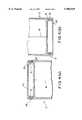
- FIG. 1 (a) and (b)are schematic views of the thermoplastic block of this invention with and without a textured surface.
- FIG. 2 (a) and (b)are top views of a section of the connecting means of adjacent thermoplastic blocks with Detail A and B enlarged.
- FIG. 3 (a), (b) and (c)are top views showing various locking positions of the thermoplastic blocks of this invention.
- FIG. 4 (a) and (b)are section views showing connecting means to a profile (i. e. bottom row of thermoplastic blocks to a floor or top row to a ceiling).
- the front and back faces of the blocksmay be positioned vertically.
- the blockis a hollow thermoplastic block with flanges on all four sides.
- the blockis symmetrical in the mid-plane that is parallel to the front and back surface of the block. Except for the front and back side, each side has two flanges.
- the inner flangesare positioned on two adjacent sides, and the outer flanges are positioned on the other two adjacent sides.
- Two outer flanges of one blockinterlock with two inner flanges of an adjacent block.
- Each flangehas an outer and an inner surface.
- the flangesconsist of a pair of inner flanges and a pair of outer flanges. As stated previously, the inner flanges are positioned on two adjacent sides and the outer flanges are positioned on the other two adjacent sides.
- Each of the flangeshave interlocking means which are molded as part of the flange and plastic block.
- the interlocking meansmay be selected from a variety of different interlocking means and may consist of grooves, ribs, tongue and grooves, or any means that can allow snap-fit of the blocks together and can be molded as part of the block during molding.
- the outer flangeshave the interlocking means on the inside surface of the flange.
- the inner flangeshave the interlocking means on the outer surface of the flange.
- the outer flangeshave on the outer surface thereof a textured surface.
- the texturemay be any texture that can be molded in the surface during molding of the plastic block.
- the texturemay consist of lines or leather like or grainy or the like.
- Such a textured surfaceprovides the advantage of being able to orientate the blocks during building a wall, i.e. the textured outer surface of the outer flanges of the block have the same orientation in an assembled wall.
- itprovides orientation of two molded halves during assembly of the two halves to form a single plastic block.
- the textured surface of the outer flangestends to block the internal view of a transparent or translucent block.
- the blockscan have more than one position relative to each other. Columns of blocks can be angled with respect to each other when seen from the top view and can thus create a curved wall in two directions.
- the dimension or configuration of the interlocking means and the distance on the flangescan define the radius of the curve of a wall designed with the thermoplastic block of this invention.
- thermoplastic resinis employed and may be a transparent, translucent or pigmented thermoplastic resin. In general, the light transmitting or transparent thermoplastic resins are preferred.
- the thermoplastic blocksmay be prepared by injection molding, vacuum forming, thermoforming, blow molding or any other molding process for forming the thermoplastic blocks of this invention.
- the thermoplastic blocks of this inventionmay be formed as a pair of halves which are at least essentially identical.
- the seam jointis generally intermediately spaced between and parallel of a pair of opposite outer side faces.
- the blocksmay be generally rectangular or square and may have rounded corners, if so desired.
- Each half membermay include an integrally molded continuous edge wall joined around the periphery of the side faces and extending inwardly thereof to a free inner edge forming a seam joint.
- the seam jointmay be a tongue and groove connection or simply adhesively butting together two halves so that when the two halves are joined together or assembled, a hollow enclosure is formed.
- the interior of the blockmay thus be sealed off against the intrusion or entry of outside elements or may have a vent hole to allow the dissipation of moisture to the atmosphere.
- FIG. 1 (a)is a schematic view of block 2 of the invention with molded insitu outer flange 4 and inner flange 6.
- FIG. 1shows one embodiment of the interconnecting means namely ribs 8. Ribs 8 are molded on underside 10 of outer flanges 4 and the outer side 12 of inner flanges 6.
- Surface 14is the front surface of block 2 with an identical surface (not shown) opposite surface 14.
- the side surfaces 16form the edge surfaces of block 2.
- seam line 18is a result of welding or bonding the two half sections together and vent opening 21 allows moisture or other gaseous elements to dissipate into the atmosphere.
- FIG. 1 (b)is the same schematic view of block 2 of FIG. 1 (a) except that outer flanges 4 have textured surface 5 consisting of lines in this embodiment. All other parts are the same as set forth in FIG. 1 (a).
- FIG. 2 (a)is a top view of a single block showing outer flanges 4 and inner flanges 6.
- FIG. 2 (b)is a top view of the section of the connecting means for joining the blocks together comprising outer flanges 4 with ribs 8, inner flanges 6 with ribs 8 and seam line 18 of block 2 showing an enlargement of detail A of the block of FIG. 2 (a), and an enlargement of detail B of an adjacent block although one block is shown since each block is essentially the same.
- FIG. 3(a), (b) and (c)illustrates the joining or connecting of two adjacent blocks FIG. 3(a) for a straight wall wherein ribs 8 of outer flange 4 and inner flange 6 join in a snap-fit without the need of motor or an adhesive.
- FIG. 3(b)illustrates how two adjacent blocks can be joined to form a curved wall by joining (snap-fit) only a portion of ribs 8 of outer flange 4 to the ribs of inner flange 6 of one side of block 2 and block 20. On the other side of block 2 and block 20, the ribs are fully joined by snap-fit of ribs 8 of outer flange 4 and the ribs of inner flange 6.
- FIG. 3(a), (b) and (c)illustrates the joining or connecting of two adjacent blocks FIG. 3(a) for a straight wall wherein ribs 8 of outer flange 4 and inner flange 6 join in a snap-fit without the need of motor or an adhesive.
- 3(c)illustrates another alternative for forming a curved wall by snap-fitting fewer of ribs 8 of outer flange 4 and the ribs of inner flange 6 on one side of block 2 and block 20.
- ribs 8 of outer flange 4 and the ribs of inner flange 6are joined by snap-fitting ribs 8.
- FIG. 4 (a)is a sectional view showing one embodiment, for connecting the top row of a wall of thermoplastic blocks 2 of this invention, for example, to a ceiling line, in order to finish the sides of a wall at the ceiling.
- Connecting means 22consists of slots 24 wherein in the embodiment outer flange 4 is inserted into slot 24. Sides 26 of slot 24 provide a finish to the edge of a wall at the ceiling.
- FIG. 4(a)also shows seam line 18.
- FIG. 4(b)illustrates one means for connecting a wall of thermoplastic blocks of the invention to a floor in order to finish the sides of the wall at the floor line.
- Connecting means 28receive inner flange 6 of block 2 such that ribs 8 snap fit into grooves 30 of connecting means 28 which secures block 2 to connecting means 28 and showing seam line 18.
- FIG. 4(a) and (b)illustrate a ceiling 4(a) and a floor 4(b) connecting means
- the ceiling connectionmay be used as a floor connecting means
- the floor connecting meansmay be used as a ceiling connecting means.
- These connecting meansmay be employed with a frame of any other structure other than a wall or ceiling.
- the flanges and interlocking sections of the flangesare molded in one operation in the molding of the thermoplastic block.
- the interlocking meansmay be any configuration, as stated previously, such as grooves or tongue and groove or ribs or any other means that can result in a snap-fit or tight connection between joining sections on the flanges of adjacent blocks.
- thermoplastic blocks of this inventionany molding means may be employed as described previously.
- the molding meansare not critical to the practice of this invention.
- the thermoplastic block with the interlocking means as part of the flangesis a critical feature of the invention such that the blocks can be joined together by merely snap-fitting the blocks through the interlocking means on the flanges.
- straight or curved wallsmay be erected without the need of motor or an adhesive.
- wallsmay be easily erected and essentially as easily disassembled on a do-it-yourself basis and without the need of construction material i. e. cement, adhesive, etc., other than just the blocks.
- the blocks of this inventionmay also have a coating over the surface of the block.
- the coatingis generally a clear coating and may be an abrasion or scratch resistant coating or the coating may be a UV resistant coating, an acrylic coating, a flame retardant coating or such other coating for purposes of abrasion resistance, chemical resistance, or the like.
- the coatingis generally applied as a secondary operation such as flow coating, dip coating, spray coating, roller coating, and the like for applying coatings to thermoplastic substrates. These coatings include, but are not limited thereto, polysiloxanes, silica filled polysiloxanes, UV resistant acrylic coatings, and the like.
- thermoplastic blocks of this inventionhave better resistance to impact than glass blocks, they are therefore more resistant to vandalism abuse such as the throwing of rocks, bottles, etc. Thus, these blocks may be installed in areas previously considered unsafe or hazardous.
- thermoplastic blocks of this inventionare architectural building blocks formed by molding a thermoplastic resin wherein the thermoplastic block comprises a hollow (polygonal shape) rectangular three dimensional thermoplastic resin block having interlocking means for joining two or more blocks to form a wall without the need of adhesive materials, and comprising two outer opposite essentially flat surfaces separated and joined around the periphery by wall segments normal to said two outer opposite essentially flat surfaces, said outer flat surfaces having flange means on all edges of each surface aligned to extend outwardly of said outer flat surface for at least partially filling a precise amount of space established between a pair of adjacent blocks when said blocks are positioned as a segment of a wall, said flange means comprising outer and inner flanges wherein each flat surface has two adjacent outer flanges and two adjacent inner flanges, said outer flanges have interlocking snap-fitting means facing inwardly from one flat outer surface and said inner flanges have interlocking snap-fitting means facing outwardly from the same flat outer surface such that the outer f
- thermoplastic blocks of this inventionAny moldable thermoplastic resin may be employed in molding the thermoplastic blocks of this invention.
- the resinsmay include aromatic carbonate homopolymers, copolymers, ester carbonate polymers; alkyl terephthalate polymers such as polybutylene terephthalate; olifin polymers such as polypropylene; and other polymers or blends thereof.
- the thermoplastic blocks of this inventionmay be transparent, translucent or opaque.
- the preferred thermoplastic reinis aromatic polycarbonate resin that is essentially transparent upon molding.
Landscapes
- Engineering & Computer Science (AREA)
- Architecture (AREA)
- Civil Engineering (AREA)
- Structural Engineering (AREA)
- Finishing Walls (AREA)
- Panels For Use In Building Construction (AREA)
- Joining Of Building Structures In Genera (AREA)
Abstract
Description
Claims (11)
Priority Applications (7)
| Application Number | Priority Date | Filing Date | Title |
|---|---|---|---|
| US08/914,687US5904019A (en) | 1997-08-19 | 1997-08-19 | Thermoplastic building blocks |
| ZA986982AZA986982B (en) | 1997-08-19 | 1998-08-04 | Thermoplastic building blocks |
| SG1998002906ASG78311A1 (en) | 1997-08-19 | 1998-08-06 | Thermoplastic building blocks |
| CN98118383ACN1208802A (en) | 1997-08-19 | 1998-08-18 | Thermoplastic Building Bricks |
| DE69832236TDE69832236T2 (en) | 1997-08-19 | 1998-08-19 | Thermoplastic building block |
| JP23243398AJP4364324B2 (en) | 1997-08-19 | 1998-08-19 | Thermoplastic resin assembly block |
| EP98306656AEP0898028B1 (en) | 1997-08-19 | 1998-08-19 | Thermoplastic building blocks |
Applications Claiming Priority (1)
| Application Number | Priority Date | Filing Date | Title |
|---|---|---|---|
| US08/914,687US5904019A (en) | 1997-08-19 | 1997-08-19 | Thermoplastic building blocks |
Publications (1)
| Publication Number | Publication Date |
|---|---|
| US5904019Atrue US5904019A (en) | 1999-05-18 |
Family
ID=25434667
Family Applications (1)
| Application Number | Title | Priority Date | Filing Date |
|---|---|---|---|
| US08/914,687Expired - LifetimeUS5904019A (en) | 1997-08-19 | 1997-08-19 | Thermoplastic building blocks |
Country Status (7)
| Country | Link |
|---|---|
| US (1) | US5904019A (en) |
| EP (1) | EP0898028B1 (en) |
| JP (1) | JP4364324B2 (en) |
| CN (1) | CN1208802A (en) |
| DE (1) | DE69832236T2 (en) |
| SG (1) | SG78311A1 (en) |
| ZA (1) | ZA986982B (en) |
Cited By (31)
| Publication number | Priority date | Publication date | Assignee | Title |
|---|---|---|---|---|
| US5970673A (en)* | 1996-02-20 | 1999-10-26 | Fisher; Myles A. | Construction block system |
| US5987829A (en)* | 1996-02-20 | 1999-11-23 | Fisher; Myles A. | Construction block |
| US6606834B2 (en)* | 1995-03-07 | 2003-08-19 | Pergo (Europe) Ab | Flooring panel or wall panel and use thereof |
| US20030208975A1 (en)* | 2002-05-08 | 2003-11-13 | Regina Samuel R. | Ventilated interlocking translucent blocks |
| US20040123540A1 (en)* | 2002-05-08 | 2004-07-01 | Regina Samuel R. | Solar reflective ventilated translucent blocks |
| US20040226239A1 (en)* | 2002-05-08 | 2004-11-18 | Regina Samuel R. | Ventilated plastic blocks with film laminate |
| US20040231273A1 (en)* | 2001-06-30 | 2004-11-25 | Guy Bamford | Laminate concrete panel |
| US20050034419A1 (en)* | 2003-07-31 | 2005-02-17 | Randall Grant E. | Snap-in panel design for a refrigeration cooler |
| US20050097860A1 (en)* | 1999-07-05 | 2005-05-12 | Goran Martensson | Floor element with guiding means |
| US7044082B1 (en)* | 2000-07-06 | 2006-05-16 | Medical Research Council | Environmental enrichment of caged animals |
| US20060265972A1 (en)* | 2005-05-31 | 2006-11-30 | Robert Kitchen | Wall construction |
| US7266930B1 (en)* | 2001-11-28 | 2007-09-11 | Us Block Windows, Inc. | Construction block |
| US20080098685A1 (en)* | 2006-10-25 | 2008-05-01 | Polk Dale E | Molded panel and panel assembly |
| US20090183455A1 (en)* | 2008-01-21 | 2009-07-23 | Lrm Industries, Llc | Load bearing assembly |
| US20100112278A1 (en)* | 2008-10-31 | 2010-05-06 | Sabic Innovative Plastics Ip B.V. | Multiwall sheet, an article, a method of making a multiwall sheet |
| US20100287866A1 (en)* | 2008-01-21 | 2010-11-18 | Nadia Rizzon | Glass element for forming glass brick walls, and process for forming walls with said element |
| US20120205388A1 (en)* | 2011-02-16 | 2012-08-16 | Seike Aya | Recyclable Thermoplastic Packaging |
| US8544233B2 (en) | 2000-03-31 | 2013-10-01 | Pergo (Europe) Ab | Building panels |
| US8601758B2 (en)* | 2011-09-08 | 2013-12-10 | Samobi Industries, Llc | Interlocking construction blocks |
| US8615952B2 (en) | 2010-01-15 | 2013-12-31 | Pergo (Europe) Ab | Set of panels comprising retaining profiles with a separate clip and method for inserting the clip |
| US8627631B2 (en) | 2000-06-20 | 2014-01-14 | Flooring Industries Limited, Sarl | Floor covering |
| WO2014014366A1 (en)* | 2012-07-16 | 2014-01-23 | Charles Caulder Bree | Interlocking blocks and tiles for buildings |
| US8661762B2 (en) | 1995-03-07 | 2014-03-04 | Pergo (Europe) Ab | Flooring panel or wall panel and use thereof |
| US8978334B2 (en) | 2010-05-10 | 2015-03-17 | Pergo (Europe) Ab | Set of panels |
| US9032685B2 (en) | 1995-03-07 | 2015-05-19 | Pergo (Europe) Ab | Flooring panel or wall panel and use thereof |
| US20150159376A1 (en)* | 2013-12-09 | 2015-06-11 | Samobi Industries, Llc | Interlocking construction blocks |
| US9322162B2 (en) | 1998-02-04 | 2016-04-26 | Pergo (Europe) Ab | Guiding means at a joint |
| US9464443B2 (en) | 1998-10-06 | 2016-10-11 | Pergo (Europe) Ab | Flooring material comprising flooring elements which are assembled by means of separate flooring elements |
| US10415241B2 (en) | 2016-03-08 | 2019-09-17 | Excel Project Management Ltd. | Monolithic retaining wall |
| US10584502B2 (en) | 2016-09-09 | 2020-03-10 | Excel Project Management Ltd. | Arch-support system |
| USD911319S1 (en)* | 2019-01-04 | 2021-02-23 | Samsung Electronics Co., Ltd. | Modular display unit |
Families Citing this family (6)
| Publication number | Priority date | Publication date | Assignee | Title |
|---|---|---|---|---|
| GB2346388A (en)* | 1999-01-22 | 2000-08-09 | Abdul Rauf | Interlocking building block with cavity for accepting ballast |
| CN1204322C (en)* | 1999-12-15 | 2005-06-01 | 有限会社日本通商 | Prefabricated Dome |
| GB2403228A (en)* | 2003-05-02 | 2004-12-29 | Philip Richardson | Blow moulded brick and method of production thereof |
| KR100941457B1 (en) | 2007-11-21 | 2010-02-11 | 허영숙 | Sidewalk block |
| ES2362513B1 (en)* | 2008-02-06 | 2012-02-14 | Universidad De Sevilla | IMPROVEMENTS INTRODUCED IN THE OBJECT OF THE MAIN PATENT P200301144 BY "SOIL OF SELF-SUPPORTING BLOCKS WITHOUT INTERIOR ARMORS". |
| CN104278786A (en)* | 2013-07-10 | 2015-01-14 | 朱朝才 | Quick-mounting/demounting plastic wall brick |
Citations (10)
| Publication number | Priority date | Publication date | Assignee | Title |
|---|---|---|---|---|
| AT169151B (en)* | 1948-12-18 | 1951-10-25 | Columbia Protektosite Co Inc | Building block and building wall made from such stones |
| FR1401279A (en)* | 1964-04-14 | 1965-06-04 | building element | |
| US4632589A (en)* | 1985-11-25 | 1986-12-30 | William Hsiu | Solder-free circuit base plate |
| US4719735A (en)* | 1987-03-27 | 1988-01-19 | Pittsburgh Corning Corporation | Translucent end cap |
| US4793104A (en)* | 1988-06-15 | 1988-12-27 | Delberg, Inc. | Guide for laying glass blocks |
| US4891925A (en)* | 1988-10-11 | 1990-01-09 | Marlon Carlson | Interconnected construction blocks |
| US4941302A (en)* | 1989-06-09 | 1990-07-17 | Libbey-Owens-Ford Co. | Insulating double glazed window assembly |
| US5033245A (en)* | 1990-01-16 | 1991-07-23 | Glass Alternatives Corp. | Architectural building block |
| US5367846A (en)* | 1993-06-14 | 1994-11-29 | Vonroenn, Jr.; Kenneth F. | Interlocking glass block system |
| US5588271A (en)* | 1992-01-30 | 1996-12-31 | Pitchford; Peter R. | Interlocking building block |
Family Cites Families (3)
| Publication number | Priority date | Publication date | Assignee | Title |
|---|---|---|---|---|
| EP0294522B1 (en)* | 1987-06-09 | 1991-07-24 | Janusz Josef Kapusta | A decorative, functional element for construction and the like |
| US5261205A (en)* | 1986-10-30 | 1993-11-16 | Sandor Frederick J | Methods and apparatus for fabricating plastic block panels |
| US5038542A (en)* | 1990-01-16 | 1991-08-13 | Glass Alternatives Corp. | Architectural building block herewith |
- 1997
- 1997-08-19USUS08/914,687patent/US5904019A/ennot_activeExpired - Lifetime
- 1998
- 1998-08-04ZAZA986982Apatent/ZA986982B/enunknown
- 1998-08-06SGSG1998002906Apatent/SG78311A1/enunknown
- 1998-08-18CNCN98118383Apatent/CN1208802A/enactivePending
- 1998-08-19JPJP23243398Apatent/JP4364324B2/ennot_activeExpired - Fee Related
- 1998-08-19DEDE69832236Tpatent/DE69832236T2/ennot_activeExpired - Lifetime
- 1998-08-19EPEP98306656Apatent/EP0898028B1/ennot_activeExpired - Lifetime
Patent Citations (12)
| Publication number | Priority date | Publication date | Assignee | Title |
|---|---|---|---|---|
| AT169151B (en)* | 1948-12-18 | 1951-10-25 | Columbia Protektosite Co Inc | Building block and building wall made from such stones |
| FR1401279A (en)* | 1964-04-14 | 1965-06-04 | building element | |
| US4632589A (en)* | 1985-11-25 | 1986-12-30 | William Hsiu | Solder-free circuit base plate |
| US4719735A (en)* | 1987-03-27 | 1988-01-19 | Pittsburgh Corning Corporation | Translucent end cap |
| US4793104A (en)* | 1988-06-15 | 1988-12-27 | Delberg, Inc. | Guide for laying glass blocks |
| US4891925A (en)* | 1988-10-11 | 1990-01-09 | Marlon Carlson | Interconnected construction blocks |
| EP0368479B1 (en)* | 1988-10-11 | 1994-03-09 | Marlon Carlson | Block wall construction system using interconnected construction blocks |
| US4941302A (en)* | 1989-06-09 | 1990-07-17 | Libbey-Owens-Ford Co. | Insulating double glazed window assembly |
| US5033245A (en)* | 1990-01-16 | 1991-07-23 | Glass Alternatives Corp. | Architectural building block |
| EP0452879B1 (en)* | 1990-04-20 | 1994-06-29 | Glass Alternatives Corp. | Architectural building block |
| US5588271A (en)* | 1992-01-30 | 1996-12-31 | Pitchford; Peter R. | Interlocking building block |
| US5367846A (en)* | 1993-06-14 | 1994-11-29 | Vonroenn, Jr.; Kenneth F. | Interlocking glass block system |
Cited By (80)
| Publication number | Priority date | Publication date | Assignee | Title |
|---|---|---|---|---|
| US6606834B2 (en)* | 1995-03-07 | 2003-08-19 | Pergo (Europe) Ab | Flooring panel or wall panel and use thereof |
| US8661762B2 (en) | 1995-03-07 | 2014-03-04 | Pergo (Europe) Ab | Flooring panel or wall panel and use thereof |
| US8875465B2 (en) | 1995-03-07 | 2014-11-04 | Pergo (Europe) Ab | Flooring panel or wall panel and use thereof |
| US9032685B2 (en) | 1995-03-07 | 2015-05-19 | Pergo (Europe) Ab | Flooring panel or wall panel and use thereof |
| US5987829A (en)* | 1996-02-20 | 1999-11-23 | Fisher; Myles A. | Construction block |
| US5970673A (en)* | 1996-02-20 | 1999-10-26 | Fisher; Myles A. | Construction block system |
| US9322162B2 (en) | 1998-02-04 | 2016-04-26 | Pergo (Europe) Ab | Guiding means at a joint |
| US9464443B2 (en) | 1998-10-06 | 2016-10-11 | Pergo (Europe) Ab | Flooring material comprising flooring elements which are assembled by means of separate flooring elements |
| US7877956B2 (en) | 1999-07-05 | 2011-02-01 | Pergo AG | Floor element with guiding means |
| US20050097860A1 (en)* | 1999-07-05 | 2005-05-12 | Goran Martensson | Floor element with guiding means |
| US10156078B2 (en) | 2000-03-31 | 2018-12-18 | Pergo (Europe) Ab | Building panels |
| US9534397B2 (en) | 2000-03-31 | 2017-01-03 | Pergo (Europe) Ab | Flooring material |
| US9611656B2 (en) | 2000-03-31 | 2017-04-04 | Pergo (Europe) Ab | Building panels |
| US9316006B2 (en) | 2000-03-31 | 2016-04-19 | Pergo (Europe) Ab | Building panels |
| US9260869B2 (en) | 2000-03-31 | 2016-02-16 | Pergo (Europe) Ab | Building panels |
| US9255414B2 (en) | 2000-03-31 | 2016-02-09 | Pergo (Europe) Ab | Building panels |
| US9677285B2 (en) | 2000-03-31 | 2017-06-13 | Pergo (Europe) Ab | Building panels |
| US10233653B2 (en) | 2000-03-31 | 2019-03-19 | Pergo (Europe) Ab | Flooring material |
| US10626619B2 (en) | 2000-03-31 | 2020-04-21 | Unilin Nordic Ab | Flooring material |
| US8578675B2 (en) | 2000-03-31 | 2013-11-12 | Pergo (Europe) Ab | Process for sealing of a joint |
| US8544233B2 (en) | 2000-03-31 | 2013-10-01 | Pergo (Europe) Ab | Building panels |
| US9388586B1 (en) | 2000-06-20 | 2016-07-12 | Flooring Industries Limited, Sarl | Floor covering |
| US8627631B2 (en) | 2000-06-20 | 2014-01-14 | Flooring Industries Limited, Sarl | Floor covering |
| US10407920B2 (en) | 2000-06-20 | 2019-09-10 | Flooring Industries Limited, Sarl | Floor covering |
| US10125498B2 (en) | 2000-06-20 | 2018-11-13 | Flooring Industries Limited, Sarl | Floor covering |
| US9856657B2 (en) | 2000-06-20 | 2018-01-02 | Flooring Industries Limited, Sarl | Floor covering |
| US8793958B2 (en) | 2000-06-20 | 2014-08-05 | Flooring Industries Limited, Sarl | Floor covering |
| US9624676B2 (en) | 2000-06-20 | 2017-04-18 | Flooring Industries Limited, Sarl | Floor covering |
| US9482013B2 (en) | 2000-06-20 | 2016-11-01 | Flooring Industries Limited, Sarl | Floor covering |
| US9394699B1 (en) | 2000-06-20 | 2016-07-19 | Flooring Industries Limited, Sarl | Floor covering |
| US9388585B1 (en) | 2000-06-20 | 2016-07-12 | Flooring Industries Limited, Sarl | Floor covering |
| US9376823B1 (en) | 2000-06-20 | 2016-06-28 | Flooring Industries Limited, Sarl | Floor covering |
| US9334657B2 (en) | 2000-06-20 | 2016-05-10 | Flooring Industries Limted, Sarl | Floor covering |
| US9068356B2 (en) | 2000-06-20 | 2015-06-30 | Flooring Industries Limited, Sarl | Floor covering |
| US8904729B2 (en) | 2000-06-20 | 2014-12-09 | Flooring Industries Limited, Sarl | Floor covering |
| US9234356B2 (en) | 2000-06-20 | 2016-01-12 | Flooring Industries Limited, Sarl | Floor covering |
| US8631625B2 (en) | 2000-06-20 | 2014-01-21 | Flooring Industries Limited, Sarl | Floor covering |
| US7044082B1 (en)* | 2000-07-06 | 2006-05-16 | Medical Research Council | Environmental enrichment of caged animals |
| US20040231273A1 (en)* | 2001-06-30 | 2004-11-25 | Guy Bamford | Laminate concrete panel |
| US7266930B1 (en)* | 2001-11-28 | 2007-09-11 | Us Block Windows, Inc. | Construction block |
| US6988341B2 (en)* | 2002-05-08 | 2006-01-24 | Regina Samuel R | Ventilated interlocking translucent blocks |
| US20060096227A1 (en)* | 2002-05-08 | 2006-05-11 | Regina Samuel R | Vented hollow plastic block |
| US20070277461A1 (en)* | 2002-05-08 | 2007-12-06 | Regina Samuel R | Ventilated translucent block with solar reflective panel |
| US20030208975A1 (en)* | 2002-05-08 | 2003-11-13 | Regina Samuel R. | Ventilated interlocking translucent blocks |
| US7150133B2 (en) | 2002-05-08 | 2006-12-19 | Samuel R. Regina | Ventilated plastic blocks with film laminate |
| US7254924B2 (en)* | 2002-05-08 | 2007-08-14 | Regina Samuel R | solar reflective ventilated translucent blocks |
| US20040123540A1 (en)* | 2002-05-08 | 2004-07-01 | Regina Samuel R. | Solar reflective ventilated translucent blocks |
| US20040226239A1 (en)* | 2002-05-08 | 2004-11-18 | Regina Samuel R. | Ventilated plastic blocks with film laminate |
| US20060096226A1 (en)* | 2002-05-08 | 2006-05-11 | Regina Samuel R | Hollow plastic block with solar reflective material |
| US20050034419A1 (en)* | 2003-07-31 | 2005-02-17 | Randall Grant E. | Snap-in panel design for a refrigeration cooler |
| US20060265972A1 (en)* | 2005-05-31 | 2006-11-30 | Robert Kitchen | Wall construction |
| US7320201B2 (en) | 2005-05-31 | 2008-01-22 | Snap Block Corp. | Wall construction |
| US20080086968A1 (en)* | 2005-05-31 | 2008-04-17 | Robert Kitchen | Wall construction |
| US20080098685A1 (en)* | 2006-10-25 | 2008-05-01 | Polk Dale E | Molded panel and panel assembly |
| US7779595B2 (en) | 2006-10-25 | 2010-08-24 | Lrm Industries International, Inc. | Molded panel and panel assembly |
| US8132378B2 (en)* | 2008-01-21 | 2012-03-13 | Nadia Rizzon | Glass element for forming glass brick walls, and process for forming walls with said element |
| US20100287866A1 (en)* | 2008-01-21 | 2010-11-18 | Nadia Rizzon | Glass element for forming glass brick walls, and process for forming walls with said element |
| US20090183455A1 (en)* | 2008-01-21 | 2009-07-23 | Lrm Industries, Llc | Load bearing assembly |
| US8091314B2 (en) | 2008-01-21 | 2012-01-10 | Lrm Industries International, Inc. | Load bearing assembly |
| US20100112278A1 (en)* | 2008-10-31 | 2010-05-06 | Sabic Innovative Plastics Ip B.V. | Multiwall sheet, an article, a method of making a multiwall sheet |
| US8889248B2 (en) | 2008-10-31 | 2014-11-18 | Sabic Global Technologies B.V. | Multiwall sheet, an article, a method of making a multiwall sheet |
| US9115500B2 (en) | 2010-01-15 | 2015-08-25 | Pergo (Europe) Ab | Set of panels comprising retaining profiles with a separate clip and method for inserting the clip |
| US8615952B2 (en) | 2010-01-15 | 2013-12-31 | Pergo (Europe) Ab | Set of panels comprising retaining profiles with a separate clip and method for inserting the clip |
| US9464444B2 (en) | 2010-01-15 | 2016-10-11 | Pergo (Europe) Ab | Set of panels comprising retaining profiles with a separate clip and method for inserting the clip |
| US8631623B2 (en) | 2010-01-15 | 2014-01-21 | Pergo (Europe) Ab | Set of panels comprising retaining profiles with a separate clip and method for inserting the clip |
| US9593491B2 (en) | 2010-05-10 | 2017-03-14 | Pergo (Europe) Ab | Set of panels |
| US8978334B2 (en) | 2010-05-10 | 2015-03-17 | Pergo (Europe) Ab | Set of panels |
| US20120205388A1 (en)* | 2011-02-16 | 2012-08-16 | Seike Aya | Recyclable Thermoplastic Packaging |
| CN103282186A (en)* | 2011-02-16 | 2013-09-04 | 英派尔科技开发有限公司 | Recyclable thermoplastic packaging |
| US8932502B2 (en)* | 2011-02-16 | 2015-01-13 | Empire Technology Development Llc | Recyclable thermoplastic packaging |
| CN103282186B (en)* | 2011-02-16 | 2016-02-17 | 英派尔科技开发有限公司 | Thermoplastic package can be recycled |
| US10028396B2 (en) | 2011-02-16 | 2018-07-17 | Empire Technology Development Llc | Recyclable thermoplastic packaging |
| US8601758B2 (en)* | 2011-09-08 | 2013-12-10 | Samobi Industries, Llc | Interlocking construction blocks |
| WO2014014366A1 (en)* | 2012-07-16 | 2014-01-23 | Charles Caulder Bree | Interlocking blocks and tiles for buildings |
| US20150152631A1 (en)* | 2012-07-16 | 2015-06-04 | Charles Caulder Bree | Interlocking blocks and tiles for buildings |
| US20150159376A1 (en)* | 2013-12-09 | 2015-06-11 | Samobi Industries, Llc | Interlocking construction blocks |
| US9068351B1 (en)* | 2013-12-09 | 2015-06-30 | Samobi Industries, Llc | Interlocking construction blocks |
| US10415241B2 (en) | 2016-03-08 | 2019-09-17 | Excel Project Management Ltd. | Monolithic retaining wall |
| US10584502B2 (en) | 2016-09-09 | 2020-03-10 | Excel Project Management Ltd. | Arch-support system |
| USD911319S1 (en)* | 2019-01-04 | 2021-02-23 | Samsung Electronics Co., Ltd. | Modular display unit |
Also Published As
| Publication number | Publication date |
|---|---|
| EP0898028B1 (en) | 2005-11-09 |
| DE69832236T2 (en) | 2006-07-27 |
| CN1208802A (en) | 1999-02-24 |
| EP0898028A2 (en) | 1999-02-24 |
| ZA986982B (en) | 1999-05-10 |
| SG78311A1 (en) | 2001-02-20 |
| JPH11131634A (en) | 1999-05-18 |
| JP4364324B2 (en) | 2009-11-18 |
| DE69832236D1 (en) | 2005-12-15 |
| EP0898028A3 (en) | 2000-02-23 |
Similar Documents
| Publication | Publication Date | Title |
|---|---|---|
| US5904019A (en) | Thermoplastic building blocks | |
| BG61882B1 (en) | MODULAR COVERS OF BUILDINGS | |
| AU646308B2 (en) | Interconnected construction blocks | |
| US5033245A (en) | Architectural building block | |
| US4047340A (en) | Swimming pool modular constructure | |
| US3593479A (en) | Molded plastic siding units | |
| US20100050548A1 (en) | Wall panel system | |
| EP0320077B1 (en) | Translucent end block | |
| CA2060379A1 (en) | Interlocking building block | |
| US3975874A (en) | Swimming pool modular construction | |
| US5367846A (en) | Interlocking glass block system | |
| US7155865B2 (en) | Prefabricated housing structure | |
| KR101147011B1 (en) | Aluminium Moulding for Decoration of Building | |
| KR20150133063A (en) | Multipurpose prefabricated panel | |
| US5687530A (en) | Composite building unit | |
| CA2111917C (en) | Modular panel for right angle interconnection | |
| US20230220677A1 (en) | Decorative quoin installation and illumination system and method | |
| GB2380742A (en) | Plastic tile roof assembly | |
| JP2003253855A (en) | Architectural plate material | |
| KR20220001810U (en) | Rain proof grill for home | |
| WO2024105253A1 (en) | Method for constructing a building, construction assembly and building comprising such construction assembly | |
| KR200287065Y1 (en) | The prefabricated panel that can change an external ornament | |
| KR20190000290U (en) | Round Type Panel for Prefabricating Round Type Building and Construction | |
| JPH0539187Y2 (en) | ||
| CA1043505A (en) | Swimming pool brace member |
Legal Events
| Date | Code | Title | Description |
|---|---|---|---|
| FEPP | Fee payment procedure | Free format text:PAYOR NUMBER ASSIGNED (ORIGINAL EVENT CODE: ASPN); ENTITY STATUS OF PATENT OWNER: LARGE ENTITY | |
| AS | Assignment | Owner name:GENERAL ELECTRIC COMPANY, NEW YORK Free format text:ASSIGNMENT OF ASSIGNORS INTEREST;ASSIGNORS:KOOIJ, GERT-JAN;GILSING, ROY;MOINAT, CHRISTOPHE SERGE;AND OTHERS;REEL/FRAME:008986/0964;SIGNING DATES FROM 19970826 TO 19970911 | |
| STCF | Information on status: patent grant | Free format text:PATENTED CASE | |
| AS | Assignment | Owner name:GENERAL ELECTRIC COMPANY, NEW YORK Free format text:ASSIGNMENT OF ASSIGNORS INTEREST;ASSIGNORS:KOOIJ, GERT-JAN;GILSING, ROY;MOINAT, CHRISTOPHE SERGE;AND OTHERS;REEL/FRAME:009996/0430;SIGNING DATES FROM 19970826 TO 19970911 | |
| FPAY | Fee payment | Year of fee payment:4 | |
| FPAY | Fee payment | Year of fee payment:8 | |
| AS | Assignment | Owner name:SABIC INNOVATIVE PLASTICS IP B.V., NETHERLANDS Free format text:ASSIGNMENT OF ASSIGNORS INTEREST;ASSIGNOR:GENERAL ELECTRIC COMPANY;REEL/FRAME:021311/0259 Effective date:20070831 | |
| AS | Assignment | Owner name:CITIBANK, N.A., AS COLLATERAL AGENT, NEW YORK Free format text:SECURITY AGREEMENT;ASSIGNOR:SABIC INNOVATIVE PLASTICS IP B.V.;REEL/FRAME:021423/0001 Effective date:20080307 Owner name:CITIBANK, N.A., AS COLLATERAL AGENT,NEW YORK Free format text:SECURITY AGREEMENT;ASSIGNOR:SABIC INNOVATIVE PLASTICS IP B.V.;REEL/FRAME:021423/0001 Effective date:20080307 | |
| FPAY | Fee payment | Year of fee payment:12 | |
| AS | Assignment | Owner name:SABIC INNOVATIVE PLASTICS IP B.V., NETHERLANDS Free format text:RELEASE BY SECURED PARTY;ASSIGNOR:CITIBANK, N.A.;REEL/FRAME:032459/0798 Effective date:20140312 | |
| AS | Assignment | Owner name:SABIC GLOBAL TECHNOLOGIES B.V., NETHERLANDS Free format text:CHANGE OF NAME;ASSIGNOR:SABIC INNOVATIVE PLASTICS IP B.V.;REEL/FRAME:038883/0906 Effective date:20140402 |