US5903844A - Method and apparatus for determining remote unit location in a communication system - Google Patents
Method and apparatus for determining remote unit location in a communication systemDownload PDFInfo
- Publication number
- US5903844A US5903844AUS08/794,708US79470897AUS5903844AUS 5903844 AUS5903844 AUS 5903844AUS 79470897 AUS79470897 AUS 79470897AUS 5903844 AUS5903844 AUS 5903844A
- Authority
- US
- United States
- Prior art keywords
- message
- remote unit
- location
- transmit
- time
- Prior art date
- Legal status (The legal status is an assumption and is not a legal conclusion. Google has not performed a legal analysis and makes no representation as to the accuracy of the status listed.)
- Expired - Lifetime
Links
- 238000004891communicationMethods0.000titleclaimsabstractdescription47
- 238000000034methodMethods0.000titleclaimsdescription50
- 230000004044responseEffects0.000claimsabstractdescription9
- 230000005540biological transmissionEffects0.000claimsdescription45
- 230000003111delayed effectEffects0.000claimsdescription2
- 230000000977initiatory effectEffects0.000abstractdescription2
- 230000001413cellular effectEffects0.000description5
- 238000010586diagramMethods0.000description4
- 238000005259measurementMethods0.000description3
- 239000011159matrix materialSubstances0.000description2
- 238000001228spectrumMethods0.000description2
- 102100022002CD59 glycoproteinHuman genes0.000description1
- 101000897400Homo sapiens CD59 glycoproteinProteins0.000description1
- 230000010267cellular communicationEffects0.000description1
- 238000010295mobile communicationMethods0.000description1
- 238000012544monitoring processMethods0.000description1
- 230000010363phase shiftEffects0.000description1
- 238000012163sequencing techniqueMethods0.000description1
- 230000011664signalingEffects0.000description1
Images


Classifications
- H—ELECTRICITY
- H04—ELECTRIC COMMUNICATION TECHNIQUE
- H04W—WIRELESS COMMUNICATION NETWORKS
- H04W64/00—Locating users or terminals or network equipment for network management purposes, e.g. mobility management
Definitions
- the present inventionrelates generally to wireless communication systems and, in particular, to a method and apparatus for remote unit location in a wireless communication system.
- a remote unit's location within a wireless communication systemmay be determined using a trilateration method. According to such a method, distances between the remote unit and multiple base stations are calculated based on a measurement of time delay of a signal traveling between the remote unit and each base station.
- a prior-art method for calculating a remote unit's locationis described in U.S. Pat. No. 5,508,708 "Method and Apparatus for Location Finding in a CDMA System" by Ghosh et al. and incorporated by reference herein. As described in U.S. Pat. No.
- the uplink signal transmitted from the remote unit to multiple base stationsis analyzed to determine propagation delay differences at each base station. From these propagation delay differences, a distance is calculated from each base station to the remote unit, and the location of the remote unit is determined.
- prior-art methods of locationcan accurately determine the location of a remote unit, these methods are limited in that they are only capable of determining the location of remote units that are actively transmitting an uplink signal. In a commercial setting, where many remote units may be idle (i.e., monitoring a paging channel, but not actively transmitting an uplink signal), prior-art methods of location may be unavailable for a large population of remote units utilizing the communication system. Thus a need exists for a method and apparatus for remote unit location in a communication system that is capable of estimating the location of a remote unit not actively transmitting an uplink signal.
- FIG. 1is a block diagram of a communication system in accordance with the preferred embodiment of the present invention.
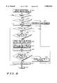
- FIG. 2is a flow chart illustrating a method of operating the communication system of FIG. 1 in accordance with the preferred embodiment of the present invention.
- FIG. 3illustrates of a Location Page Message in accordance with the preferred embodiment of the present invention.
- FIG. 4is a block diagram of the remote unit of FIG. 1 in accordance with the preferred embodiment of the present invention.
- FIG. 5is a flow chart illustrating a method of operating the logic unit of FIG. 4 in accordance with the preferred embodiment of the present invention.
- FIG. 6is a flow chart illustrating a method of operating the communication system of FIG. 1 in accordance with an alternate embodiment of the present invention.
- FIG. 7illustrates a Location Request Message in accordance with the alternate embodiment of the present invention.
- FIG. 8is a flow chart illustrating a method of operating the logic unit of FIG. 4 in accordance with the alternate embodiment of the present invention.
- the location of a remote unit within a wireless communication systemis determined by all base stations within the communication system initiating a first page (wide-area location page) that is broadcast to the remote unit over a paging channel.
- the serving and neighbor base stationsare determined from the remote unit's response to the wide-area location page and those base stations are instructed to tune receiving elements to obtain data that will be transmitted by the remote unit during location.
- a second message(Location Page Message) is then broadcast to the remote unit via the serving base station.
- the Location Page Messageinstructs the remote unit to periodically transmit a known Remote Unit Location Message (RULM) with increasing power levels a predetermined number of times so that remote unit's location can be achieved.
- RULMRemote Unit Location Message
- the present inventionencompasses a method for locating a remote unit in a communication system.
- the methodcomprises sending a first message to the remote unit instructing the remote unit to send a second message to a serving base station.
- the base stationreceives the second message transmitted from the remote unit in response to the first message and determines the serving and a neighbor base station from the second message.
- a third messageis transmitted to the remote unit instructing the remote unit to send a fourth message to the serving base station and the neighbor base station. After reception of the fourth message a location of the remote unit is determined by analyzing the fourth message.
- An alternate embodiment of the present inventionencompasses a method for locating a remote unit in a communication system.
- the methodcomprises instructing a plurality of base stations within the communication system to transmit a first message.
- the first messageinstructs the remote unit to transmit a second message at a specified time.
- the first messagealso contains a field that indicates the second message to be transmitted and a time period to begin transmission of the second message. After reception of the second message a location is determined by analyzing the second message.
- Yet another embodimentencompasses a communication system capable of transmitting a message to a remote unit.
- the communication systemcomprises a transmitter for transmitting the message.
- the messageincludes a field that indicates a second message that is to be transmitted by the remote unit. Additionally, the message includes a field that indicates when the second message is to be transmitted and a field that indicates an initial power at which the remote unit is to transmit the second message.
- the communication systemadditionally includes a location searcher for receiving the second message and determining the location of the remote unit.
- FIG. 1is a block diagram of a communication system in accordance with the preferred embodiment of the present invention.
- Wireless communication system 100is preferably a cellular communication system that utilizes a Code Division Multiple Access (CDMA) system protocol, however, in alternate embodiments of the present invention communication system 100 may utilize any analog or digital system protocol such as, but not limited to, the Advanced Mobile Phone Service (AMPS) protocol, the Global System for Mobile Communications (GSM) protocol, the Personal Digital Cellular (PDC) protocol, or the United States Digital Cellular (USDC) protocol.
- Communication system 100comprises remote unit 113, wireless infrastructure equipment, including auxiliary base station 156, Centralized Base Station Controller (CBSC) 160, Mobile Switching Center (MSC) 165, Home Location Register (HLR) 166, and base station 101.
- CDMACode Division Multiple Access
- GSMGlobal System for Mobile Communications
- PDCPersonal Digital Cellular
- USDCUnited States Digital Cellular
- Communication system 100comprises remote unit 113, wireless infrastructure equipment, including auxiliary base station 156, Centralized Base Station
- base station 101has common RF front end 105 which feeds independent rake inputs 110, 120, and 130.
- a communication system utilizing the CDMA system protocolis described in detail in TIA/EIA Interim Standard IS-95A, Mobile Station-Base Station Compatibility Standards for Dual-Mode Wideband Spread Spectrum Cellular Systems, Telecommunications Industry Association, Washington, D.C. July 1993 (IS-95A) which is incorporated by reference herein.
- Operation of Communication system 100 in accordance with the preferred embodiment of the present inventionoccurs as follows: To initiate a location request, a command is originated at a regional entity such as MSC 165, operations center 170, or perhaps within a connected network such as Public Switched Telephone Network (PSTN) 175.
- the location requestwhich includes identification information on the remote unit that is to be located, enters MSC 165.
- the location requestis passed to location searcher 167 existing in HLR 166.
- HLR 166instructs all base stations within the cellular system to send a first message to remote unit 113.
- a wide-area location pageIn particular, all base stations within the cellular system initiate a first page (hereinafter referred to as a wide-area location page) that is broadcast to remote unit 113 over a paging channel.
- the wide-area location pageis one of the Slotted Page Message (IS-95A, section 7.7.2.3.2.5), Page Message (IS-95A, section 7.7.2.3.2.6), and the General Page Message (IS-95A, section 7.7.2.3.2.17), however other pages may be utilized as well.
- the wide-area location pageis utilized to determine a gross location of remote unit 113.
- Remote unit 113responds to the wide-area location page by transmitting a message to the serving base station.
- remote unit 113sends an acknowledgment order (Ack) to the serving base station in response to the wide-area location page, which is passed though CBSC 160 to HLR 166.
- Ackis the Page Response Message as described in IS-95A, section 6.7.1.3.2.5, however in an alternate embodiment of the present invention, the wide-area location page is the Location Page Message with remote unit 113 responding by sending a RULM.
- HLR 166determines (from remote unit's 113 Ack) the base station serving remote unit 113 (i.e., serving base station that provides remote unit 113 with a reference pilot). Upon determination of the serving base station, HLR 166 determines (by accessing an internal database 168) those base stations neighboring the serving base station, and instructs CBSC 160 to tune receiving elements in the neighboring base stations to obtain data that will shortly be transmitted by remote unit 113 during location. In the preferred embodiment of the present invention, remote unit 113 is instructed when to broadcast data and all neighbor base stations are instructed as to when remote unit 113 will be transmitting. (As will be discussed below, timing information is provided to the neighbor base stations to reduce the search window when looking for the remote unit's transmissions. This window can be further reduced by taking into account certain parameters obtained in demodulating remote unit's Ack to the wide-area location page, (e.g., the delay and angle of arrival of the Ack.))
- HLR 166instructs CBSC 160 to transmit a second message (Location Page Message) via the serving base station to remote unit 113 over a paging channel.
- the Location Page Messageinstructs remote unit 113 to periodically transmit a known Remote Unit Location Message (RULM) with increasing power levels a predetermined number of times. Additionally, the Location Page Message provides remote unit 113 with a predetermined time to begin transmitting the RULM. (Further details on the Location Page Message are discussed below with reference to FIG. 3).
- remote unit 113transmits the RULM on a traffic channel using the remote unit's own public long code so that remote unit's 113 increased power transmission does not affect normal access channel messages from other remote units 113, but in alternate embodiments of the present invention, remote unit 113 may transmit the RULM via other channels (an access channel for example). Additionally, in an alternate embodiment of the present invention, remote unit 113 may transmit the RULM utilizing a specific frequency that is reserved for RULM transmission. In particular, to reduce system interference, remote unit 113 may be instructed to transmit the RULM on a frequency different than one utilized for normal traffic channel transmissions.
- RULM processor 150 of base station 101utilize detector 140 to determine propagation delay in the RULM between remote unit 113 and the base station by measuring the RULM arrival time via system clock 353. This may be accomplished as described in U.S. Pat. No. 5,508,708 by all bases determining the leading edge rise time of a specified group of Pseudo Noise (PN) chips, for example by determining the rise time for each 64th chip (i.e.., PN sequence number 0, 64, 128, etc.) for a predetermined number of chips, or may be accomplished via other location methods (e.g., U.S. Pat. No.
- PNPseudo Noise
- HLR 166instructs the serving base station to send an acknowledgment (Ack) to remote unit 113, instructing it to cease transmission.
- Ackacknowledgment
- the propagation delay at each base stationis then forwarded by each base station 101, along with its base station identification, to a designated entity, e.g. location searcher 161 of BSC 160, or location searcher 167 of HLR 166, etc., and distances between remote unit 113 and the multiple base stations are calculated (based on the measurement of the propagation delay measurements) to determine the location of remote unit 113.
- FIG. 2is a flow chart illustrating a method of operating communication system 100 of FIG. 1 in accordance with the preferred embodiment of the present invention.
- the logic flowbegins at step 201 where a location request is initiated.
- location searcher 167instructs all base stations within communication system 100 to transmit a wide-area location page.
- the wide-area location pageis utilized to determine a gross location of remote unit 113 from remote unit's 113 response to the page.
- step 215location searcher 167 determines if remote unit 113 has responded to the wide-area location page, and if not the logic flow continues to step 240 where an error message is transmitted to the regional entity that requested the location, and the logic flow ends at step 265. If at step 215 it is determined that remote unit 113 has responded to the wide-area location page, location searcher 167 determines serving and neighbor base stations (step 220) and instructs the serving and neighbor base stations to obtain data (RULM) from remote unit 113 (step 225).
- RULMserving and neighbor base stations
- the neighbor base stations stored in internal database 168are determined by geographic and propagation proximity to the serving base station, however, in an alternate embodiment of the present invention the neighbor base stations can be determined by other parameters (e.g., delay and/or sector received of the remote unit's 113 Ack to the wide-area location page).
- a Location Page Messageis transmitted to remote unit 113.
- the Location Page Messageinstructs remote unit 113 to transmit a known RULM at a specified time. (i.e. the Location Page Message identifies the RULM that remote unit 113 is to transmit along with the time the RULM is to be transmitted).
- the Location Page Messagealso instructs remote unit 113 to continue transmission of the RULM for a predetermined number of times with increasing power levels.
- RULM processor 150 of base station 101utilize detector 140 and system clock 153 to determine the chip receive times of the RULM (step 235).
- location searcher 166determines if remote unit 113 is still transmitting an RULM. If it is determined at step 250 that remote unit 113 is still transmitting an RULM the logic flow returns to step 235 where RULM receive time is again determined. However, if at step 250 it is determined that remote unit 113 has ceased transmitting an RULM, the logic flow continues to step 240 where an error message is transmitted to the regional entity requesting the location, and the logic flow ends at step 265.
- step 245the logic flow continues to step 255 where location searcher 167 instructs the serving base station to send an Ack to remote unit 113 instructing remote unit 113 to cease transmission of the RULM.
- step 260a designated entity, e.g. location searcher 161 of CBSC 160, or location searcher 167 of HLR 166 determines a location for remote unit 113. The location is passed on to the designated entity requesting location (step 260) and the logic flow ends at step 265.
- a designated entitye.g. location searcher 161 of CBSC 160, or location searcher 167 of HLR 166 determines a location for remote unit 113. The location is passed on to the designated entity requesting location (step 260) and the logic flow ends at step 265.
- FIG. 3illustrates a Location Page Message in accordance with the preferred embodiment of the present invention.
- the Location Page Messageis a variable bit message broadcast to remote unit 113 over a standard paging channel and contains fields that are described in Table 1 below:
- INC -- PWRis set to 10 dB above the remote unit's nominal transmit power described in IS-95A, section 6.1.2.3.1, however in alternate embodiments of the present invention INC -- PWR is determined by HLR 166 from the Page Response Message. In particular, in an alternate embodiment INC -- PWR is a value inversely proportional to the delay of the remote unit's 113 Ack to the wide-area location page. Additionally, in a further alternate embodiment INC -- PWR is determined from system conditions.
- INC -- PWRis reduced to 5 dB.
- remote unit 113is for remote unit 113 to transmit at full power as quickly as possible by setting both the INC -- PWR and PWR -- STEP to maximum values allowed.
- FIG. 4is a block diagram illustrating remote unit 113 of FIG. 1 in accordance with the preferred embodiment of the present invention.
- Remote unit 113comprises logic unit 401, coder 405, convolutional encoder 409, interleaver 413, orthogonal modulator 415, scrambler/spreader 421, multiplier 414, amplifier 412, system clock 433, memory 435 and upconverter 423.
- Remote unit 113transmits signal 427 utilizing the CDMA system protocol as described in IS-95A. Operation of remote unit 113 occurs as follows:
- Logic unit 401determines an RULM to be transmitted and the time, channel, frequency, and power level for its transmission.
- the RULM to be broadcastis determined from the Location Page Message that was received by the remote unit and stored in memory 435.
- logic unit 401tunes remote unit 113 to the proper frequency (RULM -- FREQ if NEW -- FREQ is 1), and outputs the RULM at a time determined by both clock 433 and the Location Page Message ACTION -- TIME.
- RULMis output as data bit stream 403.
- Data bit stream 403enters a variable-rate coder 405, which produces a signal 407 comprised of a series of transmit channel frames having varying transmit data rates. As discussed in IS-95A, transmit data rate of each frame depends on the characteristics of data bit stream 403.
- Encoder block 411includes a convolutional encoder 409 and an interleaver 413.
- each framemay be encoded by a rate 1/3 encoder using well-known algorithms such as convolutional encoding algorithms which facilitate subsequent decoding of frames.
- Interleaver 413operates to shuffle the contents of frames using commonly-known techniques such as block interleaving techniques.
- Interleaved bitsare then amplified via amplifier 412 and multiplier 414.
- Each frame of digitally coded and interleaved bitsincludes ninety-six groups of six coded bits, for a total of 576 bits. Each group of six coded bits represents an index to one of sixty-four symbols such as Walsh codes.
- a Walsh codecorresponds to a single row or column of a sixty-four-by-sixty-four Hadamard matrix, a square matrix of bits with a dimension that is a power of two.
- the bits comprising a Walsh codeare referred to as Walsh chips.
- Each of the ninety-six Walsh code indices in the frameare input to an M-ary orthogonal modulator 415, which is preferably a sixty-four-ary orthogonal modulator.
- M-ary orthogonal modulator 415For each input Walsh code index, M-ary orthogonal modulator 415 generates at output 419 a corresponding sixty-four-bit Walsh code W 417.
- a series of ninety-six Walsh codes W 417is generated for each frame input to M-ary orthogonal modulator 415.
- Scrambler/spreader block 42applies a first pseudorandom noise sequence (long code) and a second pseudorandom noise sequence to the series of Walsh codes W 417 using well-known scrambling techniques.
- the long codeis the public long code assigned to remote unit 113, however in an alternate embodiment the long code is the access channel long code.
- the scrambled series of Walsh codes W 417(representing the RULM) is phase modulated using an offset binary phase-shift keying (BPSK) modulation process or another modulation process, up-converted and transmitted as communication signal 427 from antenna 425.
- BPSKbinary phase-shift keying
- clock 433derives system time by synchronizing to transmissions from the strongest base station 101. If remote unit 113 receives a Location Page Message, system time is not changed during the location interval. In the preferred embodiment of the present invention, if the remote unit is unable to maintain synchronization with the original base station 101 an Ack is sent from remote unit 113 terminating the location signaling. In an alternative embodiment of the present invention, the remote unit derives system time from the strongest base station but does not slew its clock to the new estimate of system time during transmission of the RULM.
- FIG. 5is a flow chart illustrating a method of operating logic unit 401 of FIG. 4 in accordance with the preferred embodiment of the present invention.
- the logic flowbegins at step 501 where remote unit 113 receives a Location Page Message from a base station.
- logic unit 401determines if the COMMAND field of the Location Page Message is "01", and if not the logic flow ends at step 575, otherwise the logic flow continues to step 510 where it is determined if SEQ -- IND is set to a "1" or "0.” If at step 510 SEQ -- IND is set to "0" then remote unit 113 is to set RULM equal to the traffic channel preamble (step 515), otherwise RULM is set equal to SEQ (step 520).
- step 525logic unit 401 accesses system time from clock 433 and determines a time to broadcast the RULM. If at step 525 the system time is greater than ACTION -- TIME the logic flow continues to step 530, otherwise the logic flow returns to step 525.
- logic unit 401determines if the current time is greater than the frame in which the RULM starts (ACTION -- TIME -- FRM) plus its portion in which the RULM is prevented from being sent MSG -- SETUP -- SIZE).
- logic unit 401determines if the current time>16*(ACTION -- TIME -- FRM)+MSG -- SETUP -- SIZE, and if not, the logic flow returns to step 530, otherwise the logic flow continues to step 535 where the RULM is broadcast at an incremental transmit power level equal to INC -- PWR for a number of power control groups equal to MSG -- SIZE.
- logic unit 401instructs amplifier 412 to amplify the RULM a predetermined amount and the RULM is continuously broadcast by remote unit 113 for MSG -- SIZE power control groups.
- all serving and neighboring base stations within communication system 100are provided with the Location Page Message in order to determine the exact contents of the RULM along with the time and frame that remote unit transmits the RULM. This is done so that all serving and neighbor base stations within communication system 100 will know when to tune receiving elements for reception of the RULM transmitted by remote unit 113.
- logic unit 401instructs amplifier 412 to increase the incremented transmit power level by PWR -- STEP and counter 402 is indexed (step 545).
- logic unit 412reads the nominal power level from memory 435, adds to it the newly calculated INC -- PWR and instructs amplifier 412 to send at this power.
- logic unit 113compares the nominal power during the previous RULM to the present stores in memory 435 the larger of the two and adds it to the newly calculated INC -- PWR.
- logic unit 401instructs amplifier 412 to set the transmit power level to an absolute value determined from INC -- PWR and ignore the nominal power during the MSG -- SIZE interval. The logic flow continues to step 550.
- logic unit 401determines three conditions; 1) if the maximum number of RULM transmissions has been exceeded, 2) if remote unit 113 has transmitted the RULM at full power for greater than a predetermined number of times, and 3) if the base station has received enough data for location determination.
- these conditionsare determined by 1) determining if the counter (n) has exceeded MAX -- MSGS, 2) determining if remote unit 113 has transmitted RULMs at full power for greater than MAX -- FULL -- PWR messages, and 3) determining if an Ack has been received from a base station indicating that remote unit should cease RULM transmission.
- step 550If at step 550, all of these conditions are false, the logic flow proceeds to step 555 where ACTION -- TIME is incremented by MSG -- PERIOD and then to step 525 to await the time for the next transmission, otherwise the logic flow continues to step 557.
- step 565logic unit 401 determines if remote unit 113 should perform RULM transmissions on a periodical basis. This is accomplished by determining if REPEAT -- TIME>0. If, at step 565 it is determined that REPEAT -- TIME>0, then the logic flow continues to step 570 where remote unit 113 waits for a period of REPEAT -- TIME before returning to step 505. If, at step 565 it is determined that REPEAT -- TIME is not greater than "0", then the logic flow ends at step 575.
- Table 2illustrates the data bit stream 403 of an RULM that is two frames in duration when the SEQ field of the page message is other than all 0's.
- the time sequencing of the data stream illustrated in Table 2is firstly from left to right, secondly from top to bottom.
- the BURST -- TYPE bitsare determined by the operator 170 and the SEQ bits are that of the SEQ field of table 1.
- FIG. 6is a flow chart illustrating a method of operating the communication system of FIG. 1 in accordance with an alternate embodiment of the present invention.
- the remote unitis actively transmitting on a traffic channel when location is desired.
- the logic flowbegins at step 601 where a Location Request Message is initiated for a remote unit already in communication with base stations 101 on a traffic channel (the active base stations).
- location searcher 167determines active and neighbor base stations (step 620) and instructs the active and neighbor base stations to obtain data (RULM) from remote unit 113 (step 625).
- the neighbor base stations stored in internal database 168are determined by geographic and propagation proximity to active base stations 101 in communication with remote unit 113.
- the neighbor base stationsare additionally determined by other parameters, e.g., delay of the remote unit's frames on the traffic channel.
- a Location Request Messageis transmitted to remote unit 113 by active base stations 101.
- the Location Request Messageinstructs remote unit 113 to transmit a known RULM at a specified time, with increasing power levels.
- the Location Request Messagealso instructs remote unit 113 to continue transmission of the RULM for a predetermined period of time.
- RULM processor 150 of base stations 101utilize detector 140 and system clock 153 to determine the chip receive times of the RULM (step 635) and at step 645 it is determined if enough data has been collected to make an accurate estimation of remote unit 113 location, and if not the logic flow continues to step 650 where location searcher 166 determines if remote unit 113 is still transmitting a RULM. If it is determined at step 650 that remote unit 113 is still transmitting a RULM the logic flow returns to step 635 where chip receive times are again determined. However, if at step 650 it is determined that remote unit 113 has ceased transmitting a RULM, the logic flow sends an end-of-data message at step 660.
- step 655location searcher 167 instructs the active base stations 101 to send an Ack to remote unit 113 instructing remote unit 113 to cease transmission of the RULM.
- step 660a designated entity, e.g. location searcher 161 of CBSC 160, or location searcher 167 of HLR 166 determines a location for remote unit 113. The location is passed on to the designated entity requesting location (step 660) and the logic flow ends at step 665.
- a designated entitye.g. location searcher 161 of CBSC 160, or location searcher 167 of HLR 166 determines a location for remote unit 113. The location is passed on to the designated entity requesting location (step 660) and the logic flow ends at step 665.
- FIG. 7illustrates a Location Request Message in accordance with the alternate embodiment of the present invention.
- base stations 101interrupt the transmission of normal traffic channel frames to remote unit 113 over the assigned traffic channels by replacing one frame with the Location Request Message.
- the Location Request Messagecontains fields that are described in Table 3 below:
- the last frameis filled with SEQ bits and transmitted at nominal power.
- FIG. 8is a flow chart illustrating a method of operating logic unit 401 of FIG. 4 in accordance with the alternate embodiment of the present invention.
- the alternate embodiment of the present inventionlocates remote unit 113 when remote unit 113 is actively communicating on a traffic channel.
- the logic flowbegins at step 801 where remote unit 113 receives a Location Request Message from a base station.
- step 805logic unit 401 determines if the COMMAND field of the Location Request Message is "01", and if not the logic flow ends at step 875, otherwise the logic flow continues to step 810 where it is determined if SEQ -- IND is set to a "1" or "0.” If at step 810 SEQ -- IND is set to "0" then remote unit 113 is to set RULM equal to the traffic channel preamble (step 815), otherwise RULM is set equal to SEQ (step 820).
- step 825logic unit 401 accesses system time from clock 433 and determines a time to broadcast the RULM. If at step 825 the system time is greater than ACTION -- TIME the logic flow continues to step 830, otherwise the logic flow returns to step 825. At step 830 logic unit 401 determines if the current time is greater than the frame in which the RULM starts (ACTION -- TIME -- FRM) plus its portion in which the RULM is sent at nominal power (MSG -- SETUP -- SIZE).
- logic unit 401determines if the current time>16*(ACTION -- TIME -- FRM)+MSG -- SETUP -- SIZE, and if not, the logic flow returns to step 830, otherwise the logic flow continues to step 835 where the RULM is broadcast over the traffic channel at an incremental transmit power level equal to INC -- PWR for a number of power control groups equal to MSG -- SIZE.
- logic unit 401instructs amplifier 412 to amplify the RULM a predetermined amount during the MSG -- SIZE interval and the RULM is continuously broadcast by remote unit 113 for at least MSG -- SETUP -- SIZE+MSG -- SIZE power control groups.
- all serving and neighboring base stations within communication system 100are provided with the Location Request Message in order to determine the exact contents of the RULM along with the time and frame that remote unit 113 transmits the RULM. This is done so that all active and neighbor base stations within communication system 100 will know when to tune receiving elements for reception of the RULM transmitted by remote unit 113.
- remote unit 113ignores power control bit commands from base stations 101 during transmission of the MSG -- SIZE interval of the RULM, however, in an alternate embodiment, remote unit 113 adjusts its transmit power according the values of the power control bits during transmission of RULM.
- remote unit 113transmits the RULM on a traffic channel using the remote unit's own public long code so that remote unit's 113 increased power transmission does not affect normal access channel messages from other remote units 113, but in alternate embodiments of the present invention, remote unit 113 may transmit the RULM via other channels (an access channel for example). Additionally, in an alternate embodiment of the present invention, remote unit 113 may transmit the RULM utilizing a specific frequency that is reserved for RULM transmission. In particular, to reduce system interference, remote unit 113 may be instructed to transmit the RULM on a frequency different than one utilized for normal traffic channel transmissions.
- communication system 100may utilize the RULM reception on the new frequency as an aide in performing a hard handoff to the new frequency. In other words, communication system 100 can determine the quality of the RULM reception at the new frequency and determine if a hard handoff to that frequency is acceptable.
- logic unit 401instructs amplifier 412 to increase the transmit power level by PWR -- STEP and counter 402 is indexed (step 845).
- logic unit 412reads the nominal power level from memory 435 and adds it to the newly calculated INC -- PWR.
- logic unit 113compares the nominal power during the previous RULM to the present stores in memory 435 the larger of the two and adds it to the newly calculated INC -- PWR. The logic flow continues to step 850.
- logic unit 401instructs amplifier 412 to set the transmit power level to an absolute value determined from INC -- PWR and ignore the nominal power during the MSG -- SIZE interval.
- logic unit 401determines three conditions; 1) if the maximum number of RULM transmissions has been exceeded, 2) if remote unit 113 has transmitted at full power for greater than a predetermined number of RULMs, and 3) if the base station has received enough data for location determination.
- these conditionsare determined by 1) determining if counter 402 has exceeded MAX -- MSGS, 2) determining if remote unit 113 has transmitted at full power for greater than MAX -- FULL -- PWR RULMs, and 3) determining if an Ack has been received from an active base station indicating that remote unit 113 should cease RULM transmission.
- step 850If at step 850, all of these conditions are false, the logic flow proceeds to step 855 where ACTION -- TIME is incremented by MSG -- PERIOD and then to step 825 to await the time for the next transmission, otherwise the logic flow continues to step 860 where counter 402 is reset by setting N to "0". The logic flow ends at step 875.
Landscapes
- Engineering & Computer Science (AREA)
- Computer Networks & Wireless Communication (AREA)
- Signal Processing (AREA)
- Mobile Radio Communication Systems (AREA)
Abstract
Description
TABLE 1______________________________________Location Page Message______________________________________MSG.sub.-- TYPE to MIN2 These fields are standard for paging channel messages and are described in IS-95A, Section 7.7.2.3.2.7.COMMAND If this field is set to "00", the remote unit will send the RULM based on parameters in subsequent fields. If this field is set to "01", the remote unit will stop sending the RULM and there are no subsequent fields.SEQ.sub.-- IND If this field is set to "01", the next field will be the 8 bit sequence thatremote unit 113 is to transmit back as an RULM. If this field is set to "00",remote unit 113 will transmit standard traffic channel preamble frames as an RULM.SEQ This field stores the 8 bit sequence the remote unit is to repetitively transmit as an RULM. This field is present only if the SEQ.sub.-- IND field is "1."MSG.sub.-- SETUP.sub.-- SIZE This field is the number of power control groups the RULM is delayed prior to sending it at incremental power.INC.sub.-- PWR This field represents the incremental power at which remote unit 1.13 is to transmit the RULM. In the preferred embodiment of the present invention INC.sub.-- PWR is initially set to 10 dB above the remote unit's nominal transmit power described in IS-95A, section 6.1.2.3.1.MSG.sub.-- SIZE This field indicates the number of power control groupsremote unit 113 will transmit the 8 bit sequence or traffic channel preamble at the end of the last MSG.sub.-- SETUP.sub.-- SIZE power control group. In other words, the RULM will consist of either a repeated 8 bit sequence or a traffic channel preamble transmitted for MSG.sub.-- SIZE power control groups and starting MSG.sub.-- SETUP.sub.-- SIZE power control groups after a frame boundary.MSG.sub.-- PERIOD This field indicates the timeremote unit 113 must wait between consecutive transmission starts of the RULM.PWR.sub.-- STEP PWR.sub.-- STEP is the amount (in dB) to increase the power output (INC.sub.-- PWR) of the MSG SIZE power control groups over those of the previous RULM. In the preferred embodiment of the present invention PWR.sub.-- STEP = 5 dB.MAX.sub.-- FULL.sub.-- PWR This field represents the maximum number of RULMs thatremote unit 113 will transmit at full power before sending a special message and terminating transmission.MAX.sub.-- MSGS This field represents the maximum number of RULMs to transmit at incremented power. Each incremented power transmission message will increase by PWR.sub.-- STEP over the previous incremented power output.ACTION.sub.-- TIME This field represents the time for the beginning of the first increased power transmission. It shall be set to the System Time, in units of 80 ms (modulo 64).ACTION.sub.-- TIME.sub.-- FRM This field represents the frame number after the system time specified in ACTION.sub.-- TIME to begin the RULM..REPEAT.sub.-- TIME This field represents the time between location responses. This parameter allows the base station to requestremote unit 113 to autonomously perform the reverse traffic channel procedure on a repeated bases. If this value is set to zero, the procedure is performed by the remote unit only once.NEW.sub.-- FREQ This field indicates whether the RULM is to be sent on the present frequency or sent on another frequency. If this field is "0" the remote unit remains on the present transmit frequency. If this field is "1" the remote unit switches to a new frequency to transmit the RULM.RULM.sub.-- FREQ This field represents the CDMA Channel number corresponding to the frequency that the remote unit tunes to for sending the RULM. This field is zero length if NEW.sub.-- FREQ is "0."______________________________________
TABLE 2______________________________________Data bit stream of a two frame RULMField Length Value______________________________________CTL 4 1011MSG.sub.--TYPE 8 00000100ACK.sub.--SEQ 3 000MSG.sub.--SEQ 3 000ACK.sub.--REQ 1 1ENCRYPTION 2 00MSG.sub.--NUMBER 8 00000000BURST.sub.--TYPE 6 TBDNUM.sub.--MSGS 8 00000001NUM.sub.--FIELDS 8 00100100SEQ 8 repeated 15 timesRESERVED 1 0CTL 4 1011SEQ 8 repeated 21 times______________________________________
TABLE 3______________________________________Location Request Message______________________________________MSG.sub.-- TYPE through This field is standard for Data BurstNUM.sub.-- FIELDS Message, and is described in IS-95A, Section 7.7.3.3.2.4.COMMAND This field is set to "00", the remote unit will send the RULM based on parameters in subsequent fields. If this field is set to "01", the remote unit will stop sending the RULM and there are no subsequent fields.SEQ.sub.-- IND If this field is set to "00", the next field will be zero length and theremote unit 113 will transmit back normal traffic channel bits. If this field is set to "01", the next field will be zero length andremote unit 113 will transmit standard traffic channel preamble frames as an RULM. If this field is set to "10", the next field will be the 8 bit sequence thatremote unit 113 is to transmit back as an RULMSEQ This field stores the 8 bit sequence the remote unit is to repetitively transmit as an RULM. This field is present only if the SEQ IND field is "10."MSG.sub.-- SETUP.sub.-- SIZE This field is the number of power control groups the RULM bits are transmitted at nominal power prior to sending them at incremental power.INC.sub.-- PWR This field represents the incremental power at whichremote unit 113 is to transmit the RULM. In the alternate embodiment of the present invention INC.sub.-- PWR is set to 10 dB above the remote unit's nominal transmit power described in IS-95A, section 6.1.2.3.2MSG.sub.-- SIZE This field indicates the number of power control groupsremote unit 113 will transmit the RULM at incremental power. In other words, the RULM will consist of MSG.sub.-- SETUP.sub.-- SIZE power control groups transmitted at nominal power immediately followed by MSG.sub.-- SIZE power control groups transmitted at INC.sub.-- PWR power and the remainder of the power control groups in the frame transmitted at minimal power.MSG.sub.-- PERIOD This field indicates the timeremote unit 113 must wait between consecutive transmission starts of the RULMPWR.sub.-- STEP PWR.sub.-- STEP is the amount (in dB) to increase the power output (INC.sub.-- PWR) of the MSG SIZE power control groups over those of the previous RULM. In the alternate embodiment of the present invention PWR.sub.-- STEP = 5 dBMAX.sub.-- FULL.sub.-- PWR This field represents the maximum number of RULMs thatremote unit 113 will transmit at full power before sending a special message and terminating transmission.MAX.sub.-- MSGS This field represents the maximum number of RULMs to transmit at incremented power. Each incremented power transmission message will increase the power by PWR.sub.-- STEP over the last power outputACTION.sub.-- TIME This field represents the time for the beginning of the first increased power transmission. It shall be set to the System Time, in units of 80 ms (modulo 64)ACTION.sub.-- TIME.sub.-- FRM This field represents the frame number after the system time specified in ACTION.sub.-- TIME to begin the first increased power control transmission.______________________________________
Claims (18)
Priority Applications (9)
| Application Number | Priority Date | Filing Date | Title |
|---|---|---|---|
| US08/794,708US5903844A (en) | 1997-02-04 | 1997-02-04 | Method and apparatus for determining remote unit location in a communication system |
| CA002278764ACA2278764C (en) | 1997-02-04 | 1997-11-25 | Method and apparatus for determining remote unit location in a communication system |
| PCT/US1997/021690WO1998034423A1 (en) | 1997-02-04 | 1997-11-25 | Method and apparatus for determining remote unit location in a communication system |
| CNB971815828ACN1146251C (en) | 1997-02-04 | 1997-11-25 | Method and apparatus for determining the location of a remote unit in a communication system |
| EP97950709AEP0956715B1 (en) | 1997-02-04 | 1997-11-25 | Method for determining remote unit location in a communication system |
| JP53286498AJP3869020B2 (en) | 1997-02-04 | 1997-11-25 | Method and apparatus for determining the position of a remote unit in a communication system |
| DE69736010TDE69736010T2 (en) | 1997-02-04 | 1997-11-25 | Method for determining the position of remote units in a communication system |
| ARP980100148AAR011406A1 (en) | 1997-02-04 | 1998-01-13 | METHOD FOR LOCATING A REMOTE UNIT IN A COMMUNICATION ARRANGEMENT |
| KR1019997006947AKR100299639B1 (en) | 1997-02-04 | 1999-08-02 | Method and apparatus for determining remote unit location in a communication system |
Applications Claiming Priority (1)
| Application Number | Priority Date | Filing Date | Title |
|---|---|---|---|
| US08/794,708US5903844A (en) | 1997-02-04 | 1997-02-04 | Method and apparatus for determining remote unit location in a communication system |
Publications (1)
| Publication Number | Publication Date |
|---|---|
| US5903844Atrue US5903844A (en) | 1999-05-11 |
Family
ID=25163423
Family Applications (1)
| Application Number | Title | Priority Date | Filing Date |
|---|---|---|---|
| US08/794,708Expired - LifetimeUS5903844A (en) | 1997-02-04 | 1997-02-04 | Method and apparatus for determining remote unit location in a communication system |
Country Status (9)
| Country | Link |
|---|---|
| US (1) | US5903844A (en) |
| EP (1) | EP0956715B1 (en) |
| JP (1) | JP3869020B2 (en) |
| KR (1) | KR100299639B1 (en) |
| CN (1) | CN1146251C (en) |
| AR (1) | AR011406A1 (en) |
| CA (1) | CA2278764C (en) |
| DE (1) | DE69736010T2 (en) |
| WO (1) | WO1998034423A1 (en) |
Cited By (48)
| Publication number | Priority date | Publication date | Assignee | Title |
|---|---|---|---|---|
| US6064678A (en)* | 1997-11-07 | 2000-05-16 | Qualcomm Incorporated | Method for assigning optimal packet lengths in a variable rate communication system |
| US6064888A (en)* | 1997-11-26 | 2000-05-16 | Telefonaktiebolaget L M Ericsson (Publ) | Method and system for determining position of mobile radio terminals |
| US6160511A (en)* | 1999-09-30 | 2000-12-12 | Motorola, Inc. | Method and apparatus for locating a remote unit within a communication system |
| WO2001005185A1 (en)* | 1999-07-08 | 2001-01-18 | Ericsson Inc. | Time of arrival based positioning during handover |
| GB2355365A (en)* | 1999-08-18 | 2001-04-18 | Ico Services Ltd | Determining the location of a mobile terminal |
| US6289211B1 (en)* | 1998-03-26 | 2001-09-11 | Erksson Inc | Method for determining the position of a mobile station |
| WO2001097547A1 (en)* | 2000-06-14 | 2001-12-20 | Vist Aps | A mobile station for use as a locator device within a cellular communication system |
| US6347228B1 (en)* | 1998-06-10 | 2002-02-12 | Motorola, Inc. | Location apparatus and method in a mobile telecommunications system |
| US6445728B1 (en) | 1998-06-25 | 2002-09-03 | Samsung Electronics, Co., Ltd. | Method of establishing search window size for a mobile station in a cellular system |
| US6490455B1 (en)* | 1998-10-20 | 2002-12-03 | Samsung Electronics, Co., Ltd. | Apparatus and method for detecting a mobile phone in idle state |
| US20020186784A1 (en)* | 2001-06-09 | 2002-12-12 | Samsung Electronics Co., Ltd. | Method and apparatus for rearranging codeword sequence in a communication system |
| US20030022674A1 (en)* | 2001-07-26 | 2003-01-30 | Denso Corporation | Radio communication terminal unit and method of transmitting base station identification number |
| US6539229B1 (en)* | 1998-08-20 | 2003-03-25 | Sony Corporation | System and method for mobile location detection in synchronous wireless systems |
| WO2002047426A3 (en)* | 2000-12-08 | 2003-04-17 | Ericsson Inc | Systems and methods for improving positioning in a communications network |
| US20040029604A1 (en)* | 2000-10-10 | 2004-02-12 | Bernhard Raaf | Method and system for initiating a communication |
| US20040059978A1 (en)* | 2002-06-25 | 2004-03-25 | Parvathanathan Subrahmanya | Reduced latency for recovery from communications errors |
| US6738629B1 (en)* | 2000-05-10 | 2004-05-18 | Lucent Technologies Inc. | Method for flood paging in a telecommunications network |
| US6757537B1 (en)* | 1999-06-17 | 2004-06-29 | Samsung Electronics Co., Ltd. | Power control device and method for a mobile communication system |
| US20040203844A1 (en)* | 2002-03-20 | 2004-10-14 | Samsung Electronics Co., Ltd. | Technique to facilitate location determination of wireless data calls |
| US6812889B2 (en) | 2002-01-24 | 2004-11-02 | Motorola, Inc. | Methods and apparatus for determining a direction of arrival in a wireless communication system |
| US20040228368A1 (en)* | 2003-05-16 | 2004-11-18 | Scott Jecmen | Systems and methods for determining the delay offsets of communication systems |
| US20050070306A1 (en)* | 2003-09-29 | 2005-03-31 | Samsung Electronics Co., Ltd. | Apparatus and method for locating mobile terminals |
| RU2252429C2 (en)* | 2001-06-07 | 2005-05-20 | Корпорация "Самсунг Электроникс" | Method of finding location of mobile station |
| US20050152283A1 (en)* | 2004-01-08 | 2005-07-14 | David Ritzenthaler | Wireless device discovery |
| US6952181B2 (en) | 1996-09-09 | 2005-10-04 | Tracbeam, Llc | Locating a mobile station using a plurality of wireless networks and applications therefor |
| US20060030332A1 (en)* | 2004-08-05 | 2006-02-09 | Carrott David T | Method and system for geolocation of wireless transmissions using distributed processors in wireless receiver towers and a method for collecting a fee for processing geolocation requests |
| US20060234630A1 (en)* | 2004-12-23 | 2006-10-19 | Frederick Lai | Ping feature for electronic devices |
| DE102005041453A1 (en)* | 2005-08-31 | 2007-03-01 | Siemens Ag | Method for locating mobile phone in multi-cell wireless networks, by establishing wireless link and test data transmission between each wireless base station and mobile phone, which in turn sends reply to base station |
| US20070049251A1 (en)* | 2005-08-31 | 2007-03-01 | Mock Von A | Method and system for wireless communication in emergency situations |
| US20070149235A1 (en)* | 2005-12-23 | 2007-06-28 | Tom Chin | Method and apparatus for determining output transmit power for an access channel in a wireless communication network |
| US7274332B1 (en) | 1996-09-09 | 2007-09-25 | Tracbeam Llc | Multiple evaluators for evaluation of a purality of conditions |
| US20070243884A1 (en)* | 2002-12-27 | 2007-10-18 | Nec Corporation | Location system and method for client terminals which provide location-base service to mobile terminals |
| US7298327B2 (en) | 1996-09-09 | 2007-11-20 | Tracbeam Llc | Geographic location using multiple location estimators |
| US20090098869A1 (en)* | 2007-09-21 | 2009-04-16 | Ubinetics (Vpt) Limited | Power saving |
| US7714778B2 (en) | 1997-08-20 | 2010-05-11 | Tracbeam Llc | Wireless location gateway and applications therefor |
| US7877101B1 (en)* | 2006-12-28 | 2011-01-25 | Marvell International Ltd. | Locating a WLAN station using signal propagation delay |
| US7903029B2 (en) | 1996-09-09 | 2011-03-08 | Tracbeam Llc | Wireless location routing applications and architecture therefor |
| US7996018B1 (en)* | 2000-11-03 | 2011-08-09 | Trimble Navigation Limited | Location specific in-vehicle frequency tuning data |
| US20110260863A1 (en)* | 2008-11-06 | 2011-10-27 | Kari Juhani Hooli | Wireless Device Locations Services |
| US8082096B2 (en) | 2001-05-22 | 2011-12-20 | Tracbeam Llc | Wireless location routing applications and architecture therefor |
| US8135413B2 (en) | 1998-11-24 | 2012-03-13 | Tracbeam Llc | Platform and applications for wireless location and other complex services |
| US8694025B2 (en) | 1999-09-24 | 2014-04-08 | Dennis Dupray | Geographically constrained network services |
| US9134398B2 (en) | 1996-09-09 | 2015-09-15 | Tracbeam Llc | Wireless location using network centric location estimators |
| US9356666B1 (en)* | 2000-06-13 | 2016-05-31 | Comcast Cable Communications, Llc | Originator and recipient based transmissions in wireless communications |
| US9538493B2 (en) | 2010-08-23 | 2017-01-03 | Finetrak, Llc | Locating a mobile station and applications therefor |
| US9875492B2 (en) | 2001-05-22 | 2018-01-23 | Dennis J. Dupray | Real estate transaction system |
| US10641861B2 (en) | 2000-06-02 | 2020-05-05 | Dennis J. Dupray | Services and applications for a communications network |
| US10684350B2 (en) | 2000-06-02 | 2020-06-16 | Tracbeam Llc | Services and applications for a communications network |
Families Citing this family (4)
| Publication number | Priority date | Publication date | Assignee | Title |
|---|---|---|---|---|
| US6198935B1 (en)* | 1998-11-17 | 2001-03-06 | Ericsson Inc. | System and method for time of arrival positioning measurements based upon network characteristics |
| US20010041575A1 (en)* | 1998-11-18 | 2001-11-15 | Shahrokh Amirijoo | Positioning of gprs mobiles using toa methodology |
| EP1284580A1 (en)* | 2001-08-16 | 2003-02-19 | Swisscom Mobile AG | System and method for location update in GSM mobile radio network |
| GB2445001A (en)* | 2006-12-21 | 2008-06-25 | Siemens Ag | Determining mobile terminal location from responses to messages transmitted into different coverage areas |
Citations (13)
| Publication number | Priority date | Publication date | Assignee | Title |
|---|---|---|---|---|
| US3886554A (en)* | 1973-04-23 | 1975-05-27 | Motorola Inc | Method and apparatus for improving the accuracy of a vehicle location system |
| US3906166A (en)* | 1973-10-17 | 1975-09-16 | Motorola Inc | Radio telephone system |
| US5095500A (en)* | 1989-12-07 | 1992-03-10 | Motorola, Inc. | Cellular radiotelephone diagnostic system |
| US5208756A (en)* | 1991-01-28 | 1993-05-04 | Song Han L | Vehicle locating and navigating system |
| US5247698A (en)* | 1990-02-26 | 1993-09-21 | Telefonaktiebolaget Lm Ericsson | Use of an audit message sent to mobile stations to confirm the location thereof |
| US5404376A (en)* | 1993-09-09 | 1995-04-04 | Ericsson-Ge Mobile Communications Inc. | Navigation assistance for call handling in mobile telephone systems |
| US5428667A (en)* | 1993-03-11 | 1995-06-27 | Harris Corporation | Multi-channel cellular communications intercept system |
| US5508708A (en)* | 1995-05-08 | 1996-04-16 | Motorola, Inc. | Method and apparatus for location finding in a CDMA system |
| US5513243A (en)* | 1992-01-20 | 1996-04-30 | Nec Corporation | Person location system |
| US5583517A (en)* | 1992-08-20 | 1996-12-10 | Nexus 1994 Limited | Multi-path resistant frequency-hopped spread spectrum mobile location system |
| US5666662A (en)* | 1993-07-23 | 1997-09-09 | Nec Corporation | Method for detecting the location of a mobile terminal |
| US5675344A (en)* | 1996-06-28 | 1997-10-07 | Motorola, Inc. | Method and apparatus for locating a mobile station in a spread spectrum communication system |
| US5734963A (en)* | 1995-06-06 | 1998-03-31 | Flash Comm, Inc. | Remote initiated messaging apparatus and method in a two way wireless data communications network |
Family Cites Families (1)
| Publication number | Priority date | Publication date | Assignee | Title |
|---|---|---|---|---|
| US5613205A (en)* | 1995-03-31 | 1997-03-18 | Telefonaktiebolaget Lm Ericsson | System and method of locating a mobile terminal within the service area of a cellular telecommunication system |
- 1997
- 1997-02-04USUS08/794,708patent/US5903844A/ennot_activeExpired - Lifetime
- 1997-11-25CACA002278764Apatent/CA2278764C/ennot_activeExpired - Fee Related
- 1997-11-25EPEP97950709Apatent/EP0956715B1/ennot_activeExpired - Lifetime
- 1997-11-25WOPCT/US1997/021690patent/WO1998034423A1/enactiveIP Right Grant
- 1997-11-25DEDE69736010Tpatent/DE69736010T2/ennot_activeExpired - Lifetime
- 1997-11-25JPJP53286498Apatent/JP3869020B2/ennot_activeExpired - Fee Related
- 1997-11-25CNCNB971815828Apatent/CN1146251C/ennot_activeExpired - Fee Related
- 1998
- 1998-01-13ARARP980100148Apatent/AR011406A1/enactiveIP Right Grant
- 1999
- 1999-08-02KRKR1019997006947Apatent/KR100299639B1/ennot_activeExpired - Fee Related
Patent Citations (13)
| Publication number | Priority date | Publication date | Assignee | Title |
|---|---|---|---|---|
| US3886554A (en)* | 1973-04-23 | 1975-05-27 | Motorola Inc | Method and apparatus for improving the accuracy of a vehicle location system |
| US3906166A (en)* | 1973-10-17 | 1975-09-16 | Motorola Inc | Radio telephone system |
| US5095500A (en)* | 1989-12-07 | 1992-03-10 | Motorola, Inc. | Cellular radiotelephone diagnostic system |
| US5247698A (en)* | 1990-02-26 | 1993-09-21 | Telefonaktiebolaget Lm Ericsson | Use of an audit message sent to mobile stations to confirm the location thereof |
| US5208756A (en)* | 1991-01-28 | 1993-05-04 | Song Han L | Vehicle locating and navigating system |
| US5513243A (en)* | 1992-01-20 | 1996-04-30 | Nec Corporation | Person location system |
| US5583517A (en)* | 1992-08-20 | 1996-12-10 | Nexus 1994 Limited | Multi-path resistant frequency-hopped spread spectrum mobile location system |
| US5428667A (en)* | 1993-03-11 | 1995-06-27 | Harris Corporation | Multi-channel cellular communications intercept system |
| US5666662A (en)* | 1993-07-23 | 1997-09-09 | Nec Corporation | Method for detecting the location of a mobile terminal |
| US5404376A (en)* | 1993-09-09 | 1995-04-04 | Ericsson-Ge Mobile Communications Inc. | Navigation assistance for call handling in mobile telephone systems |
| US5508708A (en)* | 1995-05-08 | 1996-04-16 | Motorola, Inc. | Method and apparatus for location finding in a CDMA system |
| US5734963A (en)* | 1995-06-06 | 1998-03-31 | Flash Comm, Inc. | Remote initiated messaging apparatus and method in a two way wireless data communications network |
| US5675344A (en)* | 1996-06-28 | 1997-10-07 | Motorola, Inc. | Method and apparatus for locating a mobile station in a spread spectrum communication system |
Non-Patent Citations (14)
| Title |
|---|
| TIA/EIA/IS 95 A, 6.1.2.3.1 Estimated Open Loop Output Power, pp. 6 1 through 6 19.* |
| TIA/EIA/IS 95 A, 7.7.2.3.2.17 General Page Message, pp. 7 14 through 7 22.* |
| TIA/EIA/IS 95 A, 7.7.2.3.2.5 Slotted Page Message, pp. 7 8, 7 9.* |
| TIA/EIA/IS 95 A, 7.7.2.3.2.7 Order Message, pp. 7 12,7 13.* |
| TIA/EIA/IS 95 A, 7.7.3.3.2.4 Data Burst Message, pp. 7 2, 7 3.* |
| TIA/EIA/IS 95A, 6.1.2.3.2 Closed Loop Output Power, p. 7 1.* |
| TIA/EIA/IS 95A, 7.7.2.3.2.6 Page Message, pp. 7 10, 7 11.* |
| TIA/EIA/IS-95-A, 6.1.2.3.1 Estimated Open Loop Output Power, pp. 6-1 through 6-19. |
| TIA/EIA/IS-95A, 6.1.2.3.2 Closed Loop Output Power, p. 7-1. |
| TIA/EIA/IS-95-A, 7.7.2.3.2.17 General Page Message, pp. 7-14 through 7-22. |
| TIA/EIA/IS-95-A, 7.7.2.3.2.5 Slotted Page Message, pp. 7-8, 7-9. |
| TIA/EIA/IS-95A, 7.7.2.3.2.6 Page Message, pp. 7-10, 7-11. |
| TIA/EIA/IS-95-A, 7.7.2.3.2.7 Order Message, pp. 7-12,7-13. |
| TIA/EIA/IS-95-A, 7.7.3.3.2.4 Data Burst Message, pp. 7-2, 7-3. |
Cited By (105)
| Publication number | Priority date | Publication date | Assignee | Title |
|---|---|---|---|---|
| US8994591B2 (en) | 1996-09-09 | 2015-03-31 | Tracbeam Llc | Locating a mobile station and applications therefor |
| US6952181B2 (en) | 1996-09-09 | 2005-10-04 | Tracbeam, Llc | Locating a mobile station using a plurality of wireless networks and applications therefor |
| US7298327B2 (en) | 1996-09-09 | 2007-11-20 | Tracbeam Llc | Geographic location using multiple location estimators |
| US7525484B2 (en) | 1996-09-09 | 2009-04-28 | Tracbeam Llc | Gateway and hybrid solutions for wireless location |
| US9060341B2 (en) | 1996-09-09 | 2015-06-16 | Tracbeam, Llc | System and method for hybriding wireless location techniques |
| US7764231B1 (en) | 1996-09-09 | 2010-07-27 | Tracbeam Llc | Wireless location using multiple mobile station location techniques |
| US8032153B2 (en) | 1996-09-09 | 2011-10-04 | Tracbeam Llc | Multiple location estimators for wireless location |
| US7812766B2 (en) | 1996-09-09 | 2010-10-12 | Tracbeam Llc | Locating a mobile station and applications therefor |
| US9134398B2 (en) | 1996-09-09 | 2015-09-15 | Tracbeam Llc | Wireless location using network centric location estimators |
| US7274332B1 (en) | 1996-09-09 | 2007-09-25 | Tracbeam Llc | Multiple evaluators for evaluation of a purality of conditions |
| US9237543B2 (en) | 1996-09-09 | 2016-01-12 | Tracbeam, Llc | Wireless location using signal fingerprinting and other location estimators |
| US9277525B2 (en) | 1996-09-09 | 2016-03-01 | Tracbeam, Llc | Wireless location using location estimators |
| US7903029B2 (en) | 1996-09-09 | 2011-03-08 | Tracbeam Llc | Wireless location routing applications and architecture therefor |
| US7714778B2 (en) | 1997-08-20 | 2010-05-11 | Tracbeam Llc | Wireless location gateway and applications therefor |
| US6064678A (en)* | 1997-11-07 | 2000-05-16 | Qualcomm Incorporated | Method for assigning optimal packet lengths in a variable rate communication system |
| US6064888A (en)* | 1997-11-26 | 2000-05-16 | Telefonaktiebolaget L M Ericsson (Publ) | Method and system for determining position of mobile radio terminals |
| US6289211B1 (en)* | 1998-03-26 | 2001-09-11 | Erksson Inc | Method for determining the position of a mobile station |
| US6347228B1 (en)* | 1998-06-10 | 2002-02-12 | Motorola, Inc. | Location apparatus and method in a mobile telecommunications system |
| US6445728B1 (en) | 1998-06-25 | 2002-09-03 | Samsung Electronics, Co., Ltd. | Method of establishing search window size for a mobile station in a cellular system |
| US6539229B1 (en)* | 1998-08-20 | 2003-03-25 | Sony Corporation | System and method for mobile location detection in synchronous wireless systems |
| US6490455B1 (en)* | 1998-10-20 | 2002-12-03 | Samsung Electronics, Co., Ltd. | Apparatus and method for detecting a mobile phone in idle state |
| US8135413B2 (en) | 1998-11-24 | 2012-03-13 | Tracbeam Llc | Platform and applications for wireless location and other complex services |
| US6757537B1 (en)* | 1999-06-17 | 2004-06-29 | Samsung Electronics Co., Ltd. | Power control device and method for a mobile communication system |
| US6366781B1 (en) | 1999-07-08 | 2002-04-02 | Ericsson Inc. | System and method for time of arrival based positioning during handover |
| AU777073B2 (en)* | 1999-07-08 | 2004-09-30 | Ericsson Inc. | Time of arrival based positioning during handover |
| WO2001005185A1 (en)* | 1999-07-08 | 2001-01-18 | Ericsson Inc. | Time of arrival based positioning during handover |
| GB2355365A (en)* | 1999-08-18 | 2001-04-18 | Ico Services Ltd | Determining the location of a mobile terminal |
| US9078101B2 (en) | 1999-09-24 | 2015-07-07 | Dennis Dupray | Geographically constrained network services |
| US9699609B2 (en) | 1999-09-24 | 2017-07-04 | Dennis J. Dupray | Network services dependent upon geographical constraints |
| US10455356B2 (en) | 1999-09-24 | 2019-10-22 | Dennis J. Dupray | Network services dependent upon geographical constraints |
| US8694025B2 (en) | 1999-09-24 | 2014-04-08 | Dennis Dupray | Geographically constrained network services |
| US11765545B2 (en) | 1999-09-24 | 2023-09-19 | Dennis Dupray | Network services dependent on geographical constraints |
| WO2001025812A1 (en)* | 1999-09-30 | 2001-04-12 | Motorola Inc. | Locating a remote unit |
| US6160511A (en)* | 1999-09-30 | 2000-12-12 | Motorola, Inc. | Method and apparatus for locating a remote unit within a communication system |
| US6738629B1 (en)* | 2000-05-10 | 2004-05-18 | Lucent Technologies Inc. | Method for flood paging in a telecommunications network |
| US10641861B2 (en) | 2000-06-02 | 2020-05-05 | Dennis J. Dupray | Services and applications for a communications network |
| US11971491B2 (en) | 2000-06-02 | 2024-04-30 | Mobile Maven Llc | Services and applications for a communications network |
| US10684350B2 (en) | 2000-06-02 | 2020-06-16 | Tracbeam Llc | Services and applications for a communications network |
| US9356666B1 (en)* | 2000-06-13 | 2016-05-31 | Comcast Cable Communications, Llc | Originator and recipient based transmissions in wireless communications |
| US9401783B1 (en) | 2000-06-13 | 2016-07-26 | Comcast Cable Communications, Llc | Transmission of data to multiple nodes |
| US9515788B2 (en) | 2000-06-13 | 2016-12-06 | Comcast Cable Communications, Llc | Originator and recipient based transmissions in wireless communications |
| US9654323B2 (en) | 2000-06-13 | 2017-05-16 | Comcast Cable Communications, Llc | Data routing for OFDM transmission based on observed node capacities |
| US9722842B2 (en) | 2000-06-13 | 2017-08-01 | Comcast Cable Communications, Llc | Transmission of data using a plurality of radio frequency channels |
| US9820209B1 (en) | 2000-06-13 | 2017-11-14 | Comcast Cable Communications, Llc | Data routing for OFDM transmissions |
| US10257765B2 (en) | 2000-06-13 | 2019-04-09 | Comcast Cable Communications, Llc | Transmission of OFDM symbols |
| US10349332B2 (en) | 2000-06-13 | 2019-07-09 | Comcast Cable Communications, Llc | Network communication using selected resources |
| WO2001097547A1 (en)* | 2000-06-14 | 2001-12-20 | Vist Aps | A mobile station for use as a locator device within a cellular communication system |
| US7130652B2 (en)* | 2000-10-10 | 2006-10-31 | Siemens Aktiengesellschaft | Method and system for initiating a communication |
| US20040029604A1 (en)* | 2000-10-10 | 2004-02-12 | Bernhard Raaf | Method and system for initiating a communication |
| US7996018B1 (en)* | 2000-11-03 | 2011-08-09 | Trimble Navigation Limited | Location specific in-vehicle frequency tuning data |
| WO2002047426A3 (en)* | 2000-12-08 | 2003-04-17 | Ericsson Inc | Systems and methods for improving positioning in a communications network |
| US11610241B2 (en) | 2001-05-22 | 2023-03-21 | Mobile Maven Llc | Real estate transaction system |
| US9875492B2 (en) | 2001-05-22 | 2018-01-23 | Dennis J. Dupray | Real estate transaction system |
| US8082096B2 (en) | 2001-05-22 | 2011-12-20 | Tracbeam Llc | Wireless location routing applications and architecture therefor |
| RU2252429C2 (en)* | 2001-06-07 | 2005-05-20 | Корпорация "Самсунг Электроникс" | Method of finding location of mobile station |
| US7130358B2 (en)* | 2001-06-09 | 2006-10-31 | Samsung Electronics Co., Ltd. | Method and apparatus for rearranging codeword sequence in a communication system |
| US20020186784A1 (en)* | 2001-06-09 | 2002-12-12 | Samsung Electronics Co., Ltd. | Method and apparatus for rearranging codeword sequence in a communication system |
| US7047024B2 (en)* | 2001-07-26 | 2006-05-16 | Denso Corporation | Radio communication terminal unit and method of transmitting base station identification number |
| US7463895B2 (en) | 2001-07-26 | 2008-12-09 | Denso Corporation | Radio communication terminal unit and method of transmitting base station identification number |
| US20060166680A1 (en)* | 2001-07-26 | 2006-07-27 | Denso Corporation | Radio communication terminal unit and method of transmitting base station identification number |
| US20030022674A1 (en)* | 2001-07-26 | 2003-01-30 | Denso Corporation | Radio communication terminal unit and method of transmitting base station identification number |
| US6812889B2 (en) | 2002-01-24 | 2004-11-02 | Motorola, Inc. | Methods and apparatus for determining a direction of arrival in a wireless communication system |
| US20040203844A1 (en)* | 2002-03-20 | 2004-10-14 | Samsung Electronics Co., Ltd. | Technique to facilitate location determination of wireless data calls |
| US7016692B2 (en)* | 2002-03-20 | 2006-03-21 | Samsung Electronics Co., Ltd. | Technique to facilitate location determination of wireless data calls |
| US20040059978A1 (en)* | 2002-06-25 | 2004-03-25 | Parvathanathan Subrahmanya | Reduced latency for recovery from communications errors |
| US20070243884A1 (en)* | 2002-12-27 | 2007-10-18 | Nec Corporation | Location system and method for client terminals which provide location-base service to mobile terminals |
| US7761102B2 (en)* | 2002-12-27 | 2010-07-20 | Nec Corporation | Location system and method for client terminals which provide location-base service to mobile terminals |
| EP1784043B1 (en)* | 2002-12-27 | 2013-04-17 | NEC Corporation | Location system and method for client terminals which provide location-based service to mobile terminals |
| US7174133B2 (en)* | 2003-05-16 | 2007-02-06 | Agilent Technologies, Inc. | Systems and methods for determining the delay offsets of communication systems |
| US20040228368A1 (en)* | 2003-05-16 | 2004-11-18 | Scott Jecmen | Systems and methods for determining the delay offsets of communication systems |
| US7526293B2 (en)* | 2003-09-29 | 2009-04-28 | Samsung Electronics Co., Ltd | Apparatus and method for locating mobile terminals |
| US20050070306A1 (en)* | 2003-09-29 | 2005-03-31 | Samsung Electronics Co., Ltd. | Apparatus and method for locating mobile terminals |
| US20050152283A1 (en)* | 2004-01-08 | 2005-07-14 | David Ritzenthaler | Wireless device discovery |
| US20060030332A1 (en)* | 2004-08-05 | 2006-02-09 | Carrott David T | Method and system for geolocation of wireless transmissions using distributed processors in wireless receiver towers and a method for collecting a fee for processing geolocation requests |
| US20060234630A1 (en)* | 2004-12-23 | 2006-10-19 | Frederick Lai | Ping feature for electronic devices |
| US7869762B2 (en) | 2004-12-23 | 2011-01-11 | Research In Motion Limited | Ping feature for electronic devices |
| US8185051B2 (en) | 2004-12-23 | 2012-05-22 | Research In Motion Limited | Ping feature for electronic devices |
| US8583084B2 (en) | 2004-12-23 | 2013-11-12 | Blackberry Limited | Ping feature for electronic devices |
| US9046596B1 (en)* | 2005-03-21 | 2015-06-02 | Marvell International Ltd. | Systems and methods for determining a distance between a first device and a second device in a network |
| US20090149191A1 (en)* | 2005-08-31 | 2009-06-11 | Siemens Aktiengesellschaft | Method and arrangement for locating a mobile terminal in a multicell radio arrangement |
| DE102005041453B4 (en)* | 2005-08-31 | 2007-06-28 | Siemens Ag | Method and arrangement for locating a mobile terminal in a multi-cell radio arrangement |
| US20070049251A1 (en)* | 2005-08-31 | 2007-03-01 | Mock Von A | Method and system for wireless communication in emergency situations |
| WO2007027358A3 (en)* | 2005-08-31 | 2008-05-02 | Motorola Inc | Method and system for wireless communication in emergency situations |
| DE102005041453A1 (en)* | 2005-08-31 | 2007-03-01 | Siemens Ag | Method for locating mobile phone in multi-cell wireless networks, by establishing wireless link and test data transmission between each wireless base station and mobile phone, which in turn sends reply to base station |
| US8086252B2 (en) | 2005-08-31 | 2011-12-27 | Siemens Enterprise Communications Gmbh & Co. Kg | Method and arrangement for locating a mobile terminal in a multicell radio arrangement |
| US20070149235A1 (en)* | 2005-12-23 | 2007-06-28 | Tom Chin | Method and apparatus for determining output transmit power for an access channel in a wireless communication network |
| US8798661B2 (en)* | 2005-12-23 | 2014-08-05 | Qualcomm Incorporated | Method and apparatus for determining output transmit power for an access channel in a wireless communication network |
| US7996020B1 (en)* | 2006-12-28 | 2011-08-09 | Marvell International Ltd. | Locating a WLAN station using signal propagation delay |
| US7877101B1 (en)* | 2006-12-28 | 2011-01-25 | Marvell International Ltd. | Locating a WLAN station using signal propagation delay |
| US8682351B1 (en)* | 2006-12-28 | 2014-03-25 | Marvell International Ltd. | Method and apparatus for locating a WLAN station based on a propagation delay of a signal |
| US8355739B1 (en) | 2006-12-28 | 2013-01-15 | Marvell International Ltd. | Method and apparatus for locating a WLAN station based on a propagation delay of a signal |
| US20090098869A1 (en)* | 2007-09-21 | 2009-04-16 | Ubinetics (Vpt) Limited | Power saving |
| US11082959B2 (en) | 2008-11-06 | 2021-08-03 | Wireless Future Technologies Inc. | Wireless device capable of transmitting uplink sounding reference signals |
| EP2364568B1 (en)* | 2008-11-06 | 2017-12-20 | Wireless Future Technologies Inc. | Wireless device location services |
| US10194431B2 (en) | 2008-11-06 | 2019-01-29 | Wireless Future Technologies Inc. | Wireless device location services |
| US10652869B2 (en) | 2008-11-06 | 2020-05-12 | Wireless Future Technologies Inc. | Wireless device location services |
| US20110260863A1 (en)* | 2008-11-06 | 2011-10-27 | Kari Juhani Hooli | Wireless Device Locations Services |
| US9282546B2 (en) | 2008-11-06 | 2016-03-08 | Wireless Future Technologies Inc. | Wireless device location services |
| US9894482B2 (en) | 2008-11-06 | 2018-02-13 | Wireless Future Technologies Inc. | Wireless device location services |
| US11659557B2 (en) | 2008-11-06 | 2023-05-23 | Wireless Future Technologies Inc. | Wireless device capable of transmitting uplink sounding reference signals |
| US8810393B2 (en)* | 2008-11-06 | 2014-08-19 | Kari Juhani Hooli | Wireless device locations services |
| US12232122B2 (en) | 2008-11-06 | 2025-02-18 | Wireless Future Technologies Inc. | Wireless device capable of transmitting uplink sounding reference signals |
| US10849089B2 (en) | 2010-08-23 | 2020-11-24 | Finetrak, Llc | Resource allocation according to geolocation of mobile communication units |
| US9538493B2 (en) | 2010-08-23 | 2017-01-03 | Finetrak, Llc | Locating a mobile station and applications therefor |
| US12156165B2 (en) | 2010-08-23 | 2024-11-26 | Finetrak, Llc | Resource allocation according to geolocation of mobile communication units related applications |
Also Published As
| Publication number | Publication date |
|---|---|
| DE69736010T2 (en) | 2006-10-05 |
| CA2278764C (en) | 2003-08-05 |
| WO1998034423A1 (en) | 1998-08-06 |
| JP3869020B2 (en) | 2007-01-17 |
| EP0956715A4 (en) | 2002-03-13 |
| CA2278764A1 (en) | 1998-08-06 |
| JP2001509989A (en) | 2001-07-24 |
| KR100299639B1 (en) | 2001-11-03 |
| EP0956715A1 (en) | 1999-11-17 |
| CN1245615A (en) | 2000-02-23 |
| EP0956715B1 (en) | 2006-05-31 |
| CN1146251C (en) | 2004-04-14 |
| AR011406A1 (en) | 2000-08-16 |
| DE69736010D1 (en) | 2006-07-06 |
| KR20000070697A (en) | 2000-11-25 |
Similar Documents
| Publication | Publication Date | Title |
|---|---|---|
| US5903844A (en) | Method and apparatus for determining remote unit location in a communication system | |
| RU2193291C2 (en) | Method for high-speed data transmission in cellular communication equipment and device for its implementation | |
| KR100812654B1 (en) | Common control channel uplink power control for adaptive modulation and coding techniques | |
| US6775548B1 (en) | Access channel for reduced access delay in a telecommunications system | |
| JP4778045B2 (en) | Method and apparatus for performing timing synchronization with a base station | |
| EP1097524B1 (en) | Method and apparatus for fast power control of signals transmitted on a multiple access channel | |
| KR100735402B1 (en) | Apparatus and Method of Transmission Transmit Format Combination Indicator for Downlink Shared Channel in Asynchronous Mobile Communication System | |
| EP1210834B1 (en) | Method and system for initiating idle handoff in a wireless communications system | |
| KR100434466B1 (en) | apparatus and method of power control for Downlink Shared Channel in mobile communication system | |
| US6205326B1 (en) | Method for determining when a communication unit is located within a preferred zone | |
| JP4664408B2 (en) | Base station method and apparatus for supporting timing synchronization | |
| JP4773516B2 (en) | Method and apparatus for supporting uplink by a remote base station | |
| US20030087605A1 (en) | Variable rate channel quality feedback in a wireless communication system | |
| US20020122393A1 (en) | Antenna diversity in a wireless local area network | |
| US6766146B1 (en) | Channel communication device and method for mobile communication system using transmission antenna diversity | |
| US8929291B2 (en) | Apparatus and method for transmitting/receiving uplink power control information | |
| MXPA01011537A (en) | Method and apparatus for efficient candidate frequency search while initiating a handoff in a code division multiple access communication system. | |
| WO2005013509A1 (en) | Method and apparatus for power allocation to control channels in a communication system | |
| CN1350730A (en) | Adaptive power control in a radio communications system | |
| TWI301379B (en) | Radio communication system, stations for use in radio communication system and method for operating the same | |
| US7047017B2 (en) | Method for initiating a communication within a communication system | |
| WO1998054916A1 (en) | Method and apparatus for performing mobile station handoff in a code division multiple access communication system | |
| JP2005065323A (en) | Base station apparatus and radio communication method |
Legal Events
| Date | Code | Title | Description |
|---|---|---|---|
| AS | Assignment | Owner name:MOTOROLA, INC., ILLINOIS Free format text:ASSIGNMENT OF ASSIGNORS INTEREST;ASSIGNORS:BRUCKERT, EUGENE J.;SANDERS, STEPHEN H., III;REEL/FRAME:008439/0421 Effective date:19970204 | |
| STCF | Information on status: patent grant | Free format text:PATENTED CASE | |
| FPAY | Fee payment | Year of fee payment:4 | |
| FPAY | Fee payment | Year of fee payment:8 | |
| FPAY | Fee payment | Year of fee payment:12 | |
| AS | Assignment | Owner name:MOTOROLA MOBILITY, INC, ILLINOIS Free format text:ASSIGNMENT OF ASSIGNORS INTEREST;ASSIGNOR:MOTOROLA, INC;REEL/FRAME:025673/0558 Effective date:20100731 | |
| AS | Assignment | Owner name:MOTOROLA MOBILITY LLC, ILLINOIS Free format text:CHANGE OF NAME;ASSIGNOR:MOTOROLA MOBILITY, INC.;REEL/FRAME:029216/0282 Effective date:20120622 | |
| AS | Assignment | Owner name:GOOGLE TECHNOLOGY HOLDINGS LLC, CALIFORNIA Free format text:ASSIGNMENT OF ASSIGNORS INTEREST;ASSIGNOR:MOTOROLA MOBILITY LLC;REEL/FRAME:034304/0001 Effective date:20141028 |