US5903815A - Composite powdered metal component - Google Patents
Composite powdered metal componentDownload PDFInfo
- Publication number
- US5903815A US5903815AUS07/834,379US83437992AUS5903815AUS 5903815 AUS5903815 AUS 5903815AUS 83437992 AUS83437992 AUS 83437992AUS 5903815 AUS5903815 AUS 5903815A
- Authority
- US
- United States
- Prior art keywords
- die cavity
- powdered
- powdered metal
- component
- die
- Prior art date
- Legal status (The legal status is an assumption and is not a legal conclusion. Google has not performed a legal analysis and makes no representation as to the accuracy of the status listed.)
- Expired - Lifetime
Links
- 239000012255powdered metalSubstances0.000titleclaimsabstractdescription73
- 239000002131composite materialSubstances0.000titleclaimsdescription8
- OKTJSMMVPCPJKN-UHFFFAOYSA-NCarbonChemical compound[C]OKTJSMMVPCPJKN-UHFFFAOYSA-N0.000claimsabstractdescription36
- 229910052799carbonInorganic materials0.000claimsabstractdescription36
- 229910000831SteelInorganic materials0.000claimsabstractdescription21
- 238000000034methodMethods0.000claimsabstractdescription21
- 239000010959steelSubstances0.000claimsabstractdescription21
- 239000002184metalSubstances0.000claimsabstractdescription10
- 229910052751metalInorganic materials0.000claimsabstractdescription10
- 239000000843powderSubstances0.000claimsdescription18
- 238000005245sinteringMethods0.000claimsdescription11
- 239000007788liquidSubstances0.000claimsdescription5
- 238000007731hot pressingMethods0.000claimsdescription2
- 238000004512die castingMethods0.000claims1
- 238000010438heat treatmentMethods0.000claims1
- XEEYBQQBJWHFJM-UHFFFAOYSA-NIronChemical compound[Fe]XEEYBQQBJWHFJM-UHFFFAOYSA-N0.000abstractdescription12
- 239000012256powdered ironSubstances0.000abstractdescription7
- 229910052742ironInorganic materials0.000abstractdescription6
- 238000005056compactionMethods0.000abstractdescription4
- 239000000203mixtureSubstances0.000abstract1
- 229910000677High-carbon steelInorganic materials0.000description7
- 229910045601alloyInorganic materials0.000description5
- 239000000956alloySubstances0.000description5
- 238000012986modificationMethods0.000description4
- 230000004048modificationEffects0.000description4
- 229910000975Carbon steelInorganic materials0.000description3
- 229910001209Low-carbon steelInorganic materials0.000description3
- 238000000576coating methodMethods0.000description3
- 150000002739metalsChemical class0.000description3
- 239000002245particleSubstances0.000description3
- 238000011282treatmentMethods0.000description3
- 239000010962carbon steelSubstances0.000description2
- 230000006835compressionEffects0.000description2
- 238000007906compressionMethods0.000description2
- 238000009434installationMethods0.000description2
- 238000004519manufacturing processMethods0.000description2
- 239000000463materialSubstances0.000description2
- -1and thus weldableInorganic materials0.000description1
- 238000010276constructionMethods0.000description1
- 238000005242forgingMethods0.000description1
- 238000005470impregnationMethods0.000description1
- 238000003754machiningMethods0.000description1
- 238000003825pressingMethods0.000description1
- 238000003466weldingMethods0.000description1
Images


Classifications
- B—PERFORMING OPERATIONS; TRANSPORTING
- B22—CASTING; POWDER METALLURGY
- B22F—WORKING METALLIC POWDER; MANUFACTURE OF ARTICLES FROM METALLIC POWDER; MAKING METALLIC POWDER; APPARATUS OR DEVICES SPECIALLY ADAPTED FOR METALLIC POWDER
- B22F7/00—Manufacture of composite layers, workpieces, or articles, comprising metallic powder, by sintering the powder, with or without compacting wherein at least one part is obtained by sintering or compression
- B22F7/06—Manufacture of composite layers, workpieces, or articles, comprising metallic powder, by sintering the powder, with or without compacting wherein at least one part is obtained by sintering or compression of composite workpieces or articles from parts, e.g. to form tipped tools
- B—PERFORMING OPERATIONS; TRANSPORTING
- B22—CASTING; POWDER METALLURGY
- B22F—WORKING METALLIC POWDER; MANUFACTURE OF ARTICLES FROM METALLIC POWDER; MAKING METALLIC POWDER; APPARATUS OR DEVICES SPECIALLY ADAPTED FOR METALLIC POWDER
- B22F2207/00—Aspects of the compositions, gradients
- B22F2207/01—Composition gradients
- B—PERFORMING OPERATIONS; TRANSPORTING
- B22—CASTING; POWDER METALLURGY
- B22F—WORKING METALLIC POWDER; MANUFACTURE OF ARTICLES FROM METALLIC POWDER; MAKING METALLIC POWDER; APPARATUS OR DEVICES SPECIALLY ADAPTED FOR METALLIC POWDER
- B22F2998/00—Supplementary information concerning processes or compositions relating to powder metallurgy
- B22F2998/10—Processes characterised by the sequence of their steps
- B—PERFORMING OPERATIONS; TRANSPORTING
- B22—CASTING; POWDER METALLURGY
- B22F—WORKING METALLIC POWDER; MANUFACTURE OF ARTICLES FROM METALLIC POWDER; MAKING METALLIC POWDER; APPARATUS OR DEVICES SPECIALLY ADAPTED FOR METALLIC POWDER
- B22F2999/00—Aspects linked to processes or compositions used in powder metallurgy
- Y—GENERAL TAGGING OF NEW TECHNOLOGICAL DEVELOPMENTS; GENERAL TAGGING OF CROSS-SECTIONAL TECHNOLOGIES SPANNING OVER SEVERAL SECTIONS OF THE IPC; TECHNICAL SUBJECTS COVERED BY FORMER USPC CROSS-REFERENCE ART COLLECTIONS [XRACs] AND DIGESTS
- Y10—TECHNICAL SUBJECTS COVERED BY FORMER USPC
- Y10T—TECHNICAL SUBJECTS COVERED BY FORMER US CLASSIFICATION
- Y10T428/00—Stock material or miscellaneous articles
- Y10T428/12—All metal or with adjacent metals
- Y10T428/12014—All metal or with adjacent metals having metal particles
- Y10T428/12028—Composite; i.e., plural, adjacent, spatially distinct metal components [e.g., layers, etc.]
- Y10T428/12063—Nonparticulate metal component
- Y10T428/12139—Nonmetal particles in particulate component
Definitions
- the present inventionrelates to a method for constructing a composite powdered metal component.
- a die having both upper and lower die halvesis typically used to first press the component.
- the die halvesare movable with respect to each other and form a cavity therebetween which corresponds in shape to the shape of the desired finished component.
- the die cavityis filled with the powdered metal. Thereafter, the upper die half is positioned over the die cavity and the die halves are compressed together under high pressure. The compaction of the powders within the die cavity causes the metal powders to adhere to each other so that the compacted component maintains its shape upon removal from the die.
- the compacted componentis then sintered, hot pressed or hot forged to densify the part. Sintering is carried out at or near the liquids temperature and bonds the particles together while hot pressing or hot forging can be carried out at lower temperatures and densities the part at or near the liquids temperature of the metal powders. In doing so, the metal powder bonds together to form a metal component.
- powdered metal componentsare formed from powdered steel powdered iron or alloys of powdered steel and powdered iron.
- carbonIn order to increase the strength and hardness of such parts, one prior practice has been to add carbon to the powdered metal typically in the range of 0.3-1.0% by weight, which significantly increases the hardness and strength of the finished component.
- the powdered metal componentit is necessary that the powdered metal component have some porosity, and thus a lower density, in order for the part to accept certain coatings or treatments. Such increased porosity, however, usually weakens the overall part.
- the present inventionprovides a product and method for constructing a composite powdered metal component which overcomes all of the above mentioned disadvantages of the previously known practices.
- the method of the present inventionutilizes a die having two die halves.
- the die halvesare movable with respect to each other and define a die cavity between them which corresponds to the shape of the desired component.
- a first portion of the die cavityis filled with a first weldable powdered metals.
- This powdered metaltypically comprises powdered steel, powdered iron or alloys thereof having a carbon content of less than 0.6%.
- the portion of the die cavity which is filled with the first weldable powdered metalcorresponds to the portion of the final component on which the capability of performing a weld is desired.
- a powdered metaltypically comprises powdered steel, powdered iron or alloys thereof having a carbon content in excess of 0.6%.
- Such high carbon steelexhibits much greater toughness and hardness than lower carbon steels.
- the die halvesare compressed together thus compacting the powdered metal in the die cavity.
- the componentis removed from the die and sintered in an appropriate furnace.
- the sintering operationbonds the powdered metal particles together in the well known fashion to form the completed component.
- Some machining of the sintered componentmay be required.
- the component constructed according to the present inventionthus comprises two discreet regions.
- the first regionconsists of the relatively low carbon content steel which is weldable following completion of the sintering operation.
- the remainder of the componentforms the second region consisting of relatively high carbon powdered metal which, while not weldable, enjoys enhanced strength and toughness characteristics.
- Three or more regions on the component, each filled with a different powdered metal,are also possible using the method of the present invention.
- the powdered metal componentincludes at least two distinct regions which may be of the same material, but have different densities and thus different porosities.
- the low density regionmay be desirable to accept certain coatings or treatments while the higher density region is provided where high strength and hardness are desired.
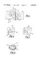
- FIG. 1is a crossectional view illustrating the method of the present invention:
- FIG. 2is a fragmentary view illustrating one step of the method of the present invention:
- FIG. 3is a fragmentary view similar to FIG. 2 but illustrating a further step of the method of the present invention:
- FIG. 4is an elevational view of the finished component made in accordance with the method of FIGS. 1-3:
- FIG. 5is a fragmentary view similar to FIG. 2 but illustrating a modification thereof:
- FIG. 6is a fragmentary view similar to FIG. 3 but illustrating a modification thereof:
- FIG. 7is a fragmentary view similar to FIG. 6 and illustrating a further step of the method of the present invention:
- FIG. 8is an elevational view showing a finished component constructed according to the method depicted in FIGS. 5-7 of the drawing:
- FIG. 9is a crossectional view illustrating a first step in an alternate embodiment of the invention:
- FIG. 10is a crossectional view illustrating a further step in the alternate embodiment of the invention.
- FIG. 11is a crossectional view illustrating another step of the alternate embodiment of the invention.
- the component 19comprises a gear having a cylindrical hub 21 and an annular gear ring 23.
- the axial end 25 of the hub 21is weldable while the remainder of the component 19 is not weldable.
- a die 10 having a lower die half 12 and an upper die half 14is thereshown.
- the die halves 12 and 14are movable with respect to each other in the direction of arrow 16 and, between them, form a die cavity 18.
- the die cavity 18corresponds in shape to the shape of the final desired component 19 (FIG. 4)
- the die cavity 18includes a cylindrical portion 20 corresponding to the hub 21 in the lower die half 18 and an outwardly extending annular portion 22 corresponding to the gear ring 23.
- this powdered metal 24comprises powdered steel, powdered iron or alloys thereof having a carbon content of less than 0.3% carbon by weight, although it can be up to 0.6% c.
- This second powdered metal 26comprises a non-weldable powdered metal, such as powdered steel, powdered iron or alloys thereof having a carbon content of greater than 0.6% carbon by weight and preferably in the range of 0.6-09% carbon by weight.
- a non-weldable powdered metalsuch as powdered steel, powdered iron or alloys thereof having a carbon content of greater than 0.6% carbon by weight and preferably in the range of 0.6-09% carbon by weight.
- Such high carbon steel or ironenjoys increased strength and toughness over lower carbon steel or iron but such high carbon steel or iron cannot be welded following completion of the manufacture of the gear.
- the upper die half 14is positioned on top of the lower die half 12 so that the powdered metals 24 and 26 are entrapped between the die halves 12 and 14 in the die cavity 18. Thereafter, a pressure is applied as indicated by arrows 28 to compact the powders together. Such pressure is typically applied in the range of 35-40 tons per square inch of die cavity surface.
- the high pressure utilized to compact the powdered metals togetherwill cause the powdered metal particles to adhere to each other so that the resulting component corresponding in shape to the die cavity 18 can be removed from the die cavity 18 as a single unit.
- This single unitwill have two discrete regions of powdered metal, namely the low carbon steel region at the axial end 25 of the hub 21 and the relatively high carbon steel throughout the remainder of the gear 19.
- the componentAfter removal of the component from the die cavity, the component is sintered at a temperature just less than liquids, i.e. between 1600° F. and 2500° F.
- the sintering operationbonds the metal powder together to form the final part.
- the component or gear 19 formed according to the present inventionincludes a relatively low carbon steel at the axial end 25 of its hub 21.
- This low carbon end 25can thus be welded to other components in the final installation of the gear 19.
- the remainder of the gear 19comprises a high carbon steel which, although it cannot be welded, enjoys greater toughness and hardness than the low carbon steel.
- the gear 30like the gear 19 shown in FIG. 4, includes both a hub 32 and a radially outwardly extending flange or gear ring 34. Unlike the gear 19 of FIG. 4, only an other ring 36 at the end of the hub 32 is formed of a low carbon, and thus weldable, steel or iron. Conversely, the inner periphery of the gear hub 32 throughout its entire length is formed of a high strength, high carbon steel.
- annular separator 40is first positioned within the lower die half 12 thus separating the lower cylindrical portion 20 of the die cavity 18 corresponding to the hub 19 into an inner ring 42 and an outer ring 44.
- the low carbon powdered steel or iron 24is then filled into the outer ring 44 of the die cavity 18.
- the separator 40prevents the low carbon powdered metal 24 from entering into the inner ring 42 of the die cavity 18.
- the remainder of the mold cavityis then filled with the high carbon powdered metal 26 and then, as shown in FIG. 7, the separator 40 is removed. Since the mold cavity is filled with powdered metal, however, the low carbon powdered metal remains substantially in the outer circumferential area at the outer axial end of the hub 20. The powdered metal in the die cavity 22 is then compacted and sintered in the previously described fashion to complete the component.
- the method of the present inventionprovides a unique method of forming a composite powdered metal part having distinct regions of weldable and non-weldable metals. Furthermore, even though the present invention has been described for manufacturing a gear having only two distinct regions of non-weldable and weldable metals, it will be understood that the part may include three or even more distinct regions of weldable and non-weldable metals without deviating from either the spirit or the scope of the present invention.
- the present inventioncan also he practiced to construct components having zones of differential hardness by using two or more powders having different carbon content.
- the final part 60(FIG. 11) has a first region 62 of relatively high porosity and thus low density, and a second region 64 of low porosity and thus high density.
- the material in each region 62 and 64may be the same.
- the high porosity region 62is desirable to accept coatings for vacuum impregnation, and/or other treatments while the higher density region 64 enjoys higher hardness and toughness as compared to the low density region 62.
- a preform 665(FIG. 9) is first formed by pressing the powdered metal together in the approximate shape of the final part. At this time, the preform 66 is of substantially uniform density.
- the preform 66is forged by dies 68. Furthermore, the dies 68 are shaped such that the inner region 64 undergoes higher compression than the outer region 62 so that the higher compression creates higher density and less porosity than the outer region 62.
- the forged preform(FIG. 10) is then sintered and machined to form the final component 60 (FIG. 11).
- the part 60 illustrated in FIG. 11is simple in construction and intended merely for purposes of illustrations. In actual practice, parts of more complex design and having two, three or even more regions of different densities can be constructed using the present invention.
Landscapes
- Chemical & Material Sciences (AREA)
- Engineering & Computer Science (AREA)
- Composite Materials (AREA)
- Manufacturing & Machinery (AREA)
- Materials Engineering (AREA)
- Mechanical Engineering (AREA)
- Powder Metallurgy (AREA)
Abstract
Description
I. Field of the Invention
The present invention relates to a method for constructing a composite powdered metal component.
II. Description of the Prior Art
In constructing components from powdered metals, a die having both upper and lower die halves is typically used to first press the component. The die halves are movable with respect to each other and form a cavity therebetween which corresponds in shape to the shape of the desired finished component.
In order to construct the powdered metal component, with the die halves separated from each other, the die cavity is filled with the powdered metal. Thereafter, the upper die half is positioned over the die cavity and the die halves are compressed together under high pressure. The compaction of the powders within the die cavity causes the metal powders to adhere to each other so that the compacted component maintains its shape upon removal from the die.
The compacted component is then sintered, hot pressed or hot forged to densify the part. Sintering is carried out at or near the liquids temperature and bonds the particles together while hot pressing or hot forging can be carried out at lower temperatures and densities the part at or near the liquids temperature of the metal powders. In doing so, the metal powder bonds together to form a metal component.
Many of these previously known powdered metal components are formed from powdered steel powdered iron or alloys of powdered steel and powdered iron. In order to increase the strength and hardness of such parts, one prior practice has been to add carbon to the powdered metal typically in the range of 0.3-1.0% by weight, which significantly increases the hardness and strength of the finished component.
One disadvantage of adding carbon to the powdered metal, however. is that the finished component cannot he welded consistently due to the relatively high carbon content. In many applications, however, it is desirable that the component exhibit the high strength of carbon steel and still maintain the capability of welding the component in its final installation.
For example, in a gear having a hub and an annular gear rings it is highly desirable that the inside diameter of the hub enjoy a high strength and rigidity of high carbon steel while other portions of the gear remain weldable In order to accomplish this, it has been the previously known practice to carborize the inside diameter of the gear hub by axially stacking a number of hubs and then flowing carbonized gas through the interior of the stacked hubs.
While this previously known practice of hardening the interior of the gear hub by forming a carborizing gas through the hub has proven effective, it is time consuming and relatively expensive to perform. Furthermore, this previously known method is effective only for increasing the carbon content along the interior of the gear hub. Conversely, this previously known method cannot be used for hardening other portions of the gear, for example, the axial end of a hub.
In still other applications. it is necessary that the powdered metal component have some porosity, and thus a lower density, in order for the part to accept certain coatings or treatments. Such increased porosity, however, usually weakens the overall part.
The present invention provides a product and method for constructing a composite powdered metal component which overcomes all of the above mentioned disadvantages of the previously known practices.
In brief, the method of the present invention utilizes a die having two die halves. The die halves are movable with respect to each other and define a die cavity between them which corresponds to the shape of the desired component.
A first portion of the die cavity is filled with a first weldable powdered metals. This powdered metal typically comprises powdered steel, powdered iron or alloys thereof having a carbon content of less than 0.6%. Furthermore, the portion of the die cavity which is filled with the first weldable powdered metal corresponds to the portion of the final component on which the capability of performing a weld is desired.
The remainder of the die cavity is filled with a second powdered metal which, after compaction, cannot be welded. Such a powdered metal typically comprises powdered steel, powdered iron or alloys thereof having a carbon content in excess of 0.6%. Such high carbon steel exhibits much greater toughness and hardness than lower carbon steels.
After the die cavity is filled, the die halves are compressed together thus compacting the powdered metal in the die cavity.
Following compaction of the component, the component is removed from the die and sintered in an appropriate furnace. The sintering operation bonds the powdered metal particles together in the well known fashion to form the completed component. Some machining of the sintered component, however, may be required.
The component constructed according to the present invention thus comprises two discreet regions. The first region consists of the relatively low carbon content steel which is weldable following completion of the sintering operation. Conversely, the remainder of the component forms the second region consisting of relatively high carbon powdered metal which, while not weldable, enjoys enhanced strength and toughness characteristics. Three or more regions on the component, each filled with a different powdered metal, are also possible using the method of the present invention.
In an alternate embodiment of the present invention, the powdered metal component includes at least two distinct regions which may be of the same material, but have different densities and thus different porosities. In such a component, the low density region may be desirable to accept certain coatings or treatments while the higher density region is provided where high strength and hardness are desired.
A better understanding of the present invention will be had upon reference to the following detailed description when read in conjunction with the accompanying drawing. Wherein like reference characters refer to like parts throughout the several views, and in which:
FIG. 1 is a crossectional view illustrating the method of the present invention:
FIG. 2 is a fragmentary view illustrating one step of the method of the present invention:
FIG. 3 is a fragmentary view similar to FIG. 2 but illustrating a further step of the method of the present invention:
FIG. 4 is an elevational view of the finished component made in accordance with the method of FIGS. 1-3:
FIG. 5 is a fragmentary view similar to FIG. 2 but illustrating a modification thereof:
FIG. 6 is a fragmentary view similar to FIG. 3 but illustrating a modification thereof:
FIG. 7 is a fragmentary view similar to FIG. 6 and illustrating a further step of the method of the present invention:
FIG. 8 is an elevational view showing a finished component constructed according to the method depicted in FIGS. 5-7 of the drawing:
FIG. 9 is a crossectional view illustrating a first step in an alternate embodiment of the invention:
FIG. 10 is a crossectional view illustrating a further step in the alternate embodiment of the invention: and
FIG. 11 is a crossectional view illustrating another step of the alternate embodiment of the invention.
With reference first to FIG. 4, acomponent 19 constructed in accordance with the method of the present invention is thereshown. For illustrative purposes, thecomponent 19 comprises a gear having acylindrical hub 21 and anannular gear ring 23. Theaxial end 25 of thehub 21 is weldable while the remainder of thecomponent 19 is not weldable.
With reference now to FIG. 19 a die 10 having alower die half 12 and anupper die half 14 is thereshown. The diehalves arrow 16 and, between them, form adie cavity 18.
Thedie cavity 18 corresponds in shape to the shape of the final desired component 19 (FIG. 4) As such, thedie cavity 18 includes acylindrical portion 20 corresponding to thehub 21 in thelower die half 18 and an outwardly extendingannular portion 22 corresponding to thegear ring 23.
With reference now to FIG. 2, in order to form the weldableaxial end 25 of thehub 21, a weldable powdered metal is first filled in the lower end of the cylindrical portion of thedie half 12. This portion of the completedcomponent 19 will thus correspond to theaxial end 25 of thegear hub 21. Typically, thispowdered metal 24 comprises powdered steel, powdered iron or alloys thereof having a carbon content of less than 0.3% carbon by weight, although it can be up to 0.6% c.
With reference now to FIG. 3, after the firstpowdered metal 24 has been filled in the lower end of thedie cavity 18, the remainder of the die cavity is filled with a secondpowdered metal 26. This secondpowdered metal 26 comprises a non-weldable powdered metal, such as powdered steel, powdered iron or alloys thereof having a carbon content of greater than 0.6% carbon by weight and preferably in the range of 0.6-09% carbon by weight. Such high carbon steel or iron enjoys increased strength and toughness over lower carbon steel or iron but such high carbon steel or iron cannot be welded following completion of the manufacture of the gear.
With reference again to FIG. 1, after thedie cavity 18 is filled with thepowdered metals upper die half 14 is positioned on top of thelower die half 12 so that thepowdered metals die cavity 18. Thereafter, a pressure is applied as indicated byarrows 28 to compact the powders together. Such pressure is typically applied in the range of 35-40 tons per square inch of die cavity surface.
The high pressure utilized to compact the powdered metals together will cause the powdered metal particles to adhere to each other so that the resulting component corresponding in shape to thedie cavity 18 can be removed from thedie cavity 18 as a single unit. This single unit, however, will have two discrete regions of powdered metal, namely the low carbon steel region at theaxial end 25 of thehub 21 and the relatively high carbon steel throughout the remainder of thegear 19.
After removal of the component from the die cavity, the component is sintered at a temperature just less than liquids, i.e. between 1600° F. and 2500° F. The sintering operation, as is well known, bonds the metal powder together to form the final part.
As shown in FIG. 4, the component orgear 19 formed according to the present invention includes a relatively low carbon steel at theaxial end 25 of itshub 21. Thislow carbon end 25 can thus be welded to other components in the final installation of thegear 19. Conversely, the remainder of thegear 19 comprises a high carbon steel which, although it cannot be welded, enjoys greater toughness and hardness than the low carbon steel.
With reference now to FIG. 5, a modification of the present invention is thereshown for producing agear 30 shown in FIG. 8. Thegear 30, like thegear 19 shown in FIG. 4, includes both ahub 32 and a radially outwardly extending flange orgear ring 34. Unlike thegear 19 of FIG. 4, only another ring 36 at the end of thehub 32 is formed of a low carbon, and thus weldable, steel or iron. Conversely, the inner periphery of thegear hub 32 throughout its entire length is formed of a high strength, high carbon steel.
With reference now to FIG. 5, in order to form thegear 30 of FIG. 8, anannular separator 40 is first positioned within thelower die half 12 thus separating the lowercylindrical portion 20 of thedie cavity 18 corresponding to thehub 19 into aninner ring 42 and anouter ring 44. The low carbon powdered steel oriron 24 is then filled into theouter ring 44 of thedie cavity 18. Theseparator 40, however, prevents the low carbon powderedmetal 24 from entering into theinner ring 42 of thedie cavity 18.
With reference now to FIG. 6, the remainder of the mold cavity is then filled with the high carbon powderedmetal 26 and then, as shown in FIG. 7, theseparator 40 is removed. Since the mold cavity is filled with powdered metal, however, the low carbon powdered metal remains substantially in the outer circumferential area at the outer axial end of thehub 20. The powdered metal in thedie cavity 22 is then compacted and sintered in the previously described fashion to complete the component.
From the foregoing, it can be seen that the method of the present invention provides a unique method of forming a composite powdered metal part having distinct regions of weldable and non-weldable metals. Furthermore, even though the present invention has been described for manufacturing a gear having only two distinct regions of non-weldable and weldable metals, it will be understood that the part may include three or even more distinct regions of weldable and non-weldable metals without deviating from either the spirit or the scope of the present invention.
The present invention can also he practiced to construct components having zones of differential hardness by using two or more powders having different carbon content.
With reference now to FIGS. 9-11, an alternate embodiment of the present invention is shown in which the final part 60 (FIG. 11) has afirst region 62 of relatively high porosity and thus low density, and asecond region 64 of low porosity and thus high density. The material in eachregion high porosity region 62 is desirable to accept coatings for vacuum impregnation, and/or other treatments while thehigher density region 64 enjoys higher hardness and toughness as compared to thelow density region 62.
In order to construct the final part 60 (FIG. 11), a preform 665 (FIG. 9) is first formed by pressing the powdered metal together in the approximate shape of the final part. At this time, thepreform 66 is of substantially uniform density.
As best shown in FIG. 10, thepreform 66 is forged by dies 68. Furthermore, the dies 68 are shaped such that theinner region 64 undergoes higher compression than theouter region 62 so that the higher compression creates higher density and less porosity than theouter region 62.
The forged preform (FIG. 10) is then sintered and machined to form the final component 60 (FIG. 11). It will be understood, of course, that the part 60 illustrated in FIG. 11 is simple in construction and intended merely for purposes of illustrations. In actual practice, parts of more complex design and having two, three or even more regions of different densities can be constructed using the present invention.
Having described my invention, however. many modifications thereto will become apparent to those skilled in the art to which it pertains without deviation from the spirit of the invention as defined by the scope of the appended claims.
Claims (12)
1. A method for constructing a composite powdered metal component with a die having at least two die parts which together define a die cavity therebetween comprising the steps of:
inserting a separator into the die cavity, said separator dividing said die cavity into a first portion and a second portion,
filling said first portion of the die cavity with a first weldable powdered metal, said die cavity having a shape corresponding to the shape of the component,
filling said second portion of the die cavity with a second non-weldable powdered metal,
removing said separator from the die casting,
compacting said first and second powders in said die cavity to form a compacted component, and
sintering said compacted component, wherein said first weldable powdered metal comprises powdered steel having a carbon content of less than 0.6% by weight and wherein said second non-weldable second powdered metal comprises powdered steel having a carbon content of more than 0.6% by weight.
2. The invention as defined in claim 1 wherein said powdered metals each comprise powdered steel and wherein said first powdered metal has a carbon content of less than 0.6% by weight while said second powdered metal has a carbon content of more than 0.67% by weight.
3. The invention as defined in claim 1 wherein said die cavity is annular in shape having an axis and wherein said second portion of said die cavity comprises one axial end of said die cavity.
4. The invention as defined in claim 1 wherein said heating step comprises hot pressing said powders.
5. The invention as defined in claim 1 wherein said sintering step is carried out at a temperature just less than the liquids temperature of said powders.
6. A method for constructing a powdered metal component having two or more regions of different density in a due cavity comprising the steps of:
inserting a separator into the die cavity, said separator dividing said cavity into a first portion and a second portion,
filling the first portion of the die cavity with a first powdered metal having a carbon content greater than 0.6% by weight, said die cavity having a shape corresponding to the shape of the component,
filling the second portion of the die cavity with a second powdered metal having a carbon content less than 0.6% by weight,
removing said separator from the die cavity,
compacting said first and second powders in said die cavity to form a compacted component, and
sintering said compacted component,
wherein the portion of the component formed by said second powder is weldable.
7. The invention as defined in claim 6 wherein said powdered metals each comprise powdered steel.
8. The invention as defined in claim 6 wherein said die cavity is annular in shape having an axis and wherein said second portion of said die cavity comprises one axial end of said mold cavity.
9. The invention as defined in claim 6 wherein said sintering step is carried out at a temperature just less than the liquids temperature of said powders.
10. A composite metal component formed by the process of:
filling a first portion of a die cavity with a first weldable powdered metal, said die cavity having a shape corresponding to the shape of the component,
filling a second portion of the die cavity with a second non-weldable powdered metal,
compacting said first and second powders in said die cavity to form a compact, and
sintering the compact, wherein said first weldable powdered metal comprises powdered steel having a carbon content of less than 0.6% by weight and wherein said second non-weldable second powdered metal comprises powdered steel having a carbon content of more than 0.6% by weight.
11. A method for constructing a composite powdered metal component with a die having two die part which together define a die cavity therebetween comprising the steps of:
inserting a separator into the die cavity, said separator dividing said die cavity into a first portion and a second portion,
filling the first portion of the die cavity with a first powdered metal, said die cavity having a shape corresponding to the shape of the component,
filling the second portion of the die cavity with a second powdered metal,
removing the separator from the die cavity,
compacting said first and second powders in said die cavity to form a compacted component, and
sintering said compacted component,
wherein said first and second powders have different carbon content so that said powders form zones of differential hardness of the component, and wherein said first weldable powdered metal comprises powdered steel having a carbon content of less than 0.6% by weight and wherein said second non-weldable second powdered metal comprises powdered steel having a carbon content of more than 0.6% by weight.
12. A method for constructing a composite powdered metal component with a die having two die parts which together define a die cavity therebetween comprising the steps of:
inserting a separator into the die cavity, said separator dividing said die cavity into a first portion and a second portion,
filling the first portion of the die cavity with a first powdered metal, said die cavity having a shape corresponding to the shape of the component,
filling the second portion of the die cavity with a second powdered metal,
removing the separator from the die cavity,
compacting said first and second powders in said die cavity to form a compacted component, and
sintering said compacted component, wherein said first weldable powdered metal comprises powdered steel having a carbon content of less than 0.6% by weight and wherein said second non-weldable second powdered metal comprises powdered steel having a carbon content of more than 0.6% by weight.
Priority Applications (2)
| Application Number | Priority Date | Filing Date | Title |
|---|---|---|---|
| US07/834,379US5903815A (en) | 1992-02-12 | 1992-02-12 | Composite powdered metal component |
| CA002089433ACA2089433C (en) | 1992-02-12 | 1993-02-12 | Composite powdered metal component |
Applications Claiming Priority (1)
| Application Number | Priority Date | Filing Date | Title |
|---|---|---|---|
| US07/834,379US5903815A (en) | 1992-02-12 | 1992-02-12 | Composite powdered metal component |
Publications (1)
| Publication Number | Publication Date |
|---|---|
| US5903815Atrue US5903815A (en) | 1999-05-11 |
Family
ID=25266799
Family Applications (1)
| Application Number | Title | Priority Date | Filing Date |
|---|---|---|---|
| US07/834,379Expired - LifetimeUS5903815A (en) | 1992-02-12 | 1992-02-12 | Composite powdered metal component |
Country Status (2)
| Country | Link |
|---|---|
| US (1) | US5903815A (en) |
| CA (1) | CA2089433C (en) |
Cited By (30)
| Publication number | Priority date | Publication date | Assignee | Title |
|---|---|---|---|---|
| US6253443B1 (en)* | 1997-09-30 | 2001-07-03 | Scimed Life Systems, Inc. | Method of forming a stent |
| US6306340B1 (en) | 1999-10-22 | 2001-10-23 | Daimlerchrysler Corporation | Method of making a brake rotor |
| US6730263B2 (en)* | 1998-11-02 | 2004-05-04 | Gkn Sinter Metals Gmbh | Process to manufacture a sintered part with a subsequent shaping of the green compact |
| US20050242528A1 (en)* | 2004-04-30 | 2005-11-03 | Nikonchuk Vincent A | Seal assembly with dual density powder metal seat member |
| US20060170301A1 (en)* | 2004-04-06 | 2006-08-03 | Masahiro Masuzawa | Rotor and process for manufacturing the same |
| US20060275607A1 (en)* | 2005-06-06 | 2006-12-07 | Semih Demir | Composite assemblies including powdered metal components |
| DE102005027140A1 (en)* | 2005-06-10 | 2006-12-14 | Gkn Sinter Metals Gmbh | Gearing with adapted sintered material |
| DE102005027907A1 (en)* | 2005-06-10 | 2006-12-14 | Gkn Sinter Metals Gmbh | Forged toothing |
| WO2006131348A2 (en) | 2005-06-10 | 2006-12-14 | Gkn Sinter Metals Holding Gmbh | Blank geometry of an undersized gear made of sintered material |
| WO2006131356A2 (en) | 2005-06-10 | 2006-12-14 | Gkn Sinter Metals Holding Gmbh | Work piece having different qualities |
| DE102005027137A1 (en)* | 2005-06-10 | 2006-12-14 | Gkn Sinter Metals Gmbh | Gearing made of sintered material |
| DE102005027050A1 (en)* | 2005-06-10 | 2006-12-14 | Gkn Sinter Metals Gmbh | Motor vehicle component with toothing |
| US20070028446A1 (en)* | 2002-05-17 | 2007-02-08 | Schwabische Huttenwerke Gmbh | Gear wheel with a multiple helical toothing, pressed in one part, and a method and device for manufacturing the same |
| US20070221005A1 (en)* | 2006-03-24 | 2007-09-27 | Gkn Sinter Metals, Inc. | Composite powder metal variable boundary gear and method |
| US20080152940A1 (en)* | 2005-06-10 | 2008-06-26 | Gerhard Kotthoff | Hardness and roughness of toothed section from a surface-densified sintered material |
| US20080166579A1 (en)* | 2005-06-10 | 2008-07-10 | Gerhard Kotthoff | Sintered Gear Element Featuring Locally Selective Surface Compression |
| US20080170960A1 (en)* | 2005-06-10 | 2008-07-17 | Gerhard Kotthoff | Surface Compression Of A Toothed Section |
| WO2008043709A3 (en)* | 2006-10-12 | 2008-09-18 | Bosch Gmbh Robert | Hand machine-tool, especially electrical shears |
| WO2009025661A1 (en)* | 2007-08-17 | 2009-02-26 | Gkn Sinter Metals, Llc | Composite powder metal variable boundary gear and method |
| US7531151B1 (en) | 2005-03-04 | 2009-05-12 | Saint Marys Pressed Metal, Inc. | Powdered metals extracted from acid mine drainage and their use in the manufacture of pressed metal articles |
| US20100279807A1 (en)* | 2006-10-24 | 2010-11-04 | Miba Sinter Austria Gmbh | Method For The Production Of A One-Piece Metallic Multiple Wheel, Preform For The Production Thereof, And Multiple Wheel |
| CN1973002B (en)* | 2004-05-12 | 2011-08-17 | 阿尔发-凯尔塞特填料有限公司 | Surface-modified inorganic filler and pigment |
| US20130079182A1 (en)* | 2011-09-23 | 2013-03-28 | Briggs & Stratton Corporation | Pulley system for outdoor power equipment |
| US20130093552A1 (en)* | 2010-06-30 | 2013-04-18 | Qingkai Wang | Neodymium-Iron-Boron Magnet having Gradient Coercive Force and its Preparation Method |
| US8613143B2 (en)* | 2010-12-29 | 2013-12-24 | Magna Powertrain Of America, Inc. | Beveloid planetary gear drive for transfer case or transmission |
| US9856962B2 (en) | 2006-03-24 | 2018-01-02 | Gkn Sinter Metals, Llc | Forged composite powder metal part and method of making same |
| US20210145474A1 (en)* | 2019-11-20 | 2021-05-20 | Boston Scientific Scimed, Inc. | Composite atherectomy burr |
| IT202100018326A1 (en)* | 2021-07-12 | 2023-01-12 | Hgears Ag | METHOD FOR MAKING A METALLIC PIECE |
| US11879447B2 (en) | 2020-09-09 | 2024-01-23 | Waukesha Bearings Corporation | Composite structures for reciprocating gas compressor systems |
| US12297867B2 (en) | 2020-09-08 | 2025-05-13 | Dover Pumps & Process Solutions Segment, Inc. | Functionally graded composite structures |
Citations (9)
| Publication number | Priority date | Publication date | Assignee | Title |
|---|---|---|---|---|
| US3373003A (en)* | 1965-04-01 | 1968-03-12 | Siemens Ag | Multi-layer bonded metal structure |
| US4214906A (en)* | 1974-11-29 | 1980-07-29 | Volkswagenwerk Aktiengesellschaft | Method of producing an article which comprises a first zone of a nonoxide ceramic material and a second zone of a softer material |
| US4329175A (en)* | 1977-04-01 | 1982-05-11 | Rolls-Royce Limited | Products made by powder metallurgy and a method therefore |
| US4472350A (en)* | 1982-06-09 | 1984-09-18 | Nippon Piston Ring Co., Ltd. | Method of making a compound valve seat |
| US4503009A (en)* | 1982-05-08 | 1985-03-05 | Hitachi Powdered Metals Co., Ltd. | Process for making composite mechanical parts by sintering |
| US5043123A (en)* | 1989-05-24 | 1991-08-27 | Mannesmann Aktiengesellschaft | Method and apparatus for manufacturing finished parts as composite bodies from pulverulent rolling materials |
| US5056209A (en)* | 1988-12-09 | 1991-10-15 | Sumitomo Metal Industries, Ltd. | Process for manufacturing clad metal tubing |
| US5069866A (en)* | 1989-06-01 | 1991-12-03 | Abb Stal Ab | Method for manufacturing a compound pipe |
| US5110349A (en)* | 1989-11-15 | 1992-05-05 | Sandvik Ab | Cutting insert of sintered hard alloy |
- 1992
- 1992-02-12USUS07/834,379patent/US5903815A/ennot_activeExpired - Lifetime
- 1993
- 1993-02-12CACA002089433Apatent/CA2089433C/ennot_activeExpired - Fee Related
Patent Citations (9)
| Publication number | Priority date | Publication date | Assignee | Title |
|---|---|---|---|---|
| US3373003A (en)* | 1965-04-01 | 1968-03-12 | Siemens Ag | Multi-layer bonded metal structure |
| US4214906A (en)* | 1974-11-29 | 1980-07-29 | Volkswagenwerk Aktiengesellschaft | Method of producing an article which comprises a first zone of a nonoxide ceramic material and a second zone of a softer material |
| US4329175A (en)* | 1977-04-01 | 1982-05-11 | Rolls-Royce Limited | Products made by powder metallurgy and a method therefore |
| US4503009A (en)* | 1982-05-08 | 1985-03-05 | Hitachi Powdered Metals Co., Ltd. | Process for making composite mechanical parts by sintering |
| US4472350A (en)* | 1982-06-09 | 1984-09-18 | Nippon Piston Ring Co., Ltd. | Method of making a compound valve seat |
| US5056209A (en)* | 1988-12-09 | 1991-10-15 | Sumitomo Metal Industries, Ltd. | Process for manufacturing clad metal tubing |
| US5043123A (en)* | 1989-05-24 | 1991-08-27 | Mannesmann Aktiengesellschaft | Method and apparatus for manufacturing finished parts as composite bodies from pulverulent rolling materials |
| US5069866A (en)* | 1989-06-01 | 1991-12-03 | Abb Stal Ab | Method for manufacturing a compound pipe |
| US5110349A (en)* | 1989-11-15 | 1992-05-05 | Sandvik Ab | Cutting insert of sintered hard alloy |
Non-Patent Citations (5)
| Title |
|---|
| Hirschhorn, "Intro to Powder Metallurgy," American Powder Metallurgy Institute, 1969, pp. 96-99. |
| Hirschhorn, Intro to Powder Metallurgy, American Powder Metallurgy Institute, 1969, pp. 96 99.* |
| Klar et al., Metals Handbook Ninth Edition, vol. 7, Powder Metallurgy, American Soc. for Metals, pp. 308, 309; 1984.* |
| McGannon, "The Making, Shaping, and Treating of Steel", United States Steel, 8th ed. 1964, pp. 1069-1073, 1111-1116. |
| McGannon, The Making, Shaping, and Treating of Steel , United States Steel, 8th ed. 1964, pp. 1069 1073, 1111 1116.* |
Cited By (55)
| Publication number | Priority date | Publication date | Assignee | Title |
|---|---|---|---|---|
| US7963990B2 (en) | 1997-09-30 | 2011-06-21 | Boston Scientific Scimed, Inc. | Stent drug delivery system |
| US6253443B1 (en)* | 1997-09-30 | 2001-07-03 | Scimed Life Systems, Inc. | Method of forming a stent |
| US20080288059A1 (en)* | 1997-09-30 | 2008-11-20 | Boston Scientific Scimed Inc. | Stent Drug Delivery System |
| US6730263B2 (en)* | 1998-11-02 | 2004-05-04 | Gkn Sinter Metals Gmbh | Process to manufacture a sintered part with a subsequent shaping of the green compact |
| US6306340B1 (en) | 1999-10-22 | 2001-10-23 | Daimlerchrysler Corporation | Method of making a brake rotor |
| US7761995B2 (en)* | 2002-05-17 | 2010-07-27 | Schwaebische Huettenwerke Automotive Gmbh & Co. Kg | Gear wheel with a multiple helical toothing, pressed in one part, and a method and device for manufacturing the same |
| US20070028446A1 (en)* | 2002-05-17 | 2007-02-08 | Schwabische Huttenwerke Gmbh | Gear wheel with a multiple helical toothing, pressed in one part, and a method and device for manufacturing the same |
| US20060170301A1 (en)* | 2004-04-06 | 2006-08-03 | Masahiro Masuzawa | Rotor and process for manufacturing the same |
| US7981359B2 (en)* | 2004-04-06 | 2011-07-19 | Hitachi Metals, Ltd. | Rotor and process for manufacturing the same |
| US20050242528A1 (en)* | 2004-04-30 | 2005-11-03 | Nikonchuk Vincent A | Seal assembly with dual density powder metal seat member |
| CN1973002B (en)* | 2004-05-12 | 2011-08-17 | 阿尔发-凯尔塞特填料有限公司 | Surface-modified inorganic filler and pigment |
| US7531151B1 (en) | 2005-03-04 | 2009-05-12 | Saint Marys Pressed Metal, Inc. | Powdered metals extracted from acid mine drainage and their use in the manufacture of pressed metal articles |
| US20060275607A1 (en)* | 2005-06-06 | 2006-12-07 | Semih Demir | Composite assemblies including powdered metal components |
| US8402659B2 (en) | 2005-06-10 | 2013-03-26 | Gkn Sinter Metals Holding Gmbh | Sintered gear element featuring locally selective surface compression |
| DE102005027050A1 (en)* | 2005-06-10 | 2006-12-14 | Gkn Sinter Metals Gmbh | Motor vehicle component with toothing |
| US20080138562A1 (en)* | 2005-06-10 | 2008-06-12 | Gerhard Kotthoff | Automotive Component Comprising A Toothed Section |
| US20080152940A1 (en)* | 2005-06-10 | 2008-06-26 | Gerhard Kotthoff | Hardness and roughness of toothed section from a surface-densified sintered material |
| US20080166579A1 (en)* | 2005-06-10 | 2008-07-10 | Gerhard Kotthoff | Sintered Gear Element Featuring Locally Selective Surface Compression |
| US20080170960A1 (en)* | 2005-06-10 | 2008-07-17 | Gerhard Kotthoff | Surface Compression Of A Toothed Section |
| US20080201951A1 (en)* | 2005-06-10 | 2008-08-28 | Gerhard Kotthoff | Work Piece Having Different Qualities |
| US20080209730A1 (en)* | 2005-06-10 | 2008-09-04 | Gerhard Kotthoff | Surface-Densified Toothed Section From A Sintered Material And Having Special Tolerances |
| DE102005027050B4 (en) | 2005-06-10 | 2021-12-30 | Gkn Sinter Metals Gmbh | Motor vehicle component with toothing |
| US20120227530A1 (en)* | 2005-06-10 | 2012-09-13 | Gerhard Kotthoff | Work Piece Having Different Qualities |
| US20080134507A1 (en)* | 2005-06-10 | 2008-06-12 | Gerhard Kotthoff | Blank Geometry Of A Gear |
| US8307551B2 (en) | 2005-06-10 | 2012-11-13 | Gkn Sinter Metals Holding Gmbh | Blank geometry of a gear |
| US8340806B2 (en) | 2005-06-10 | 2012-12-25 | Gkn Sinter Metals Holding Gmbh | Surface compression of a toothed section |
| DE102005027907A1 (en)* | 2005-06-10 | 2006-12-14 | Gkn Sinter Metals Gmbh | Forged toothing |
| DE102005027137A1 (en)* | 2005-06-10 | 2006-12-14 | Gkn Sinter Metals Gmbh | Gearing made of sintered material |
| DE102005027140A1 (en)* | 2005-06-10 | 2006-12-14 | Gkn Sinter Metals Gmbh | Gearing with adapted sintered material |
| WO2006131348A2 (en) | 2005-06-10 | 2006-12-14 | Gkn Sinter Metals Holding Gmbh | Blank geometry of an undersized gear made of sintered material |
| WO2006131356A2 (en) | 2005-06-10 | 2006-12-14 | Gkn Sinter Metals Holding Gmbh | Work piece having different qualities |
| US20100322812A1 (en)* | 2006-03-24 | 2010-12-23 | Geiman Timothy E | Method of forming composite powder metal gear |
| US8424204B2 (en) | 2006-03-24 | 2013-04-23 | Gkn Sinter Metals, Llc | Method of forming composite powder metal gear |
| US9856962B2 (en) | 2006-03-24 | 2018-01-02 | Gkn Sinter Metals, Llc | Forged composite powder metal part and method of making same |
| US10900552B2 (en) | 2006-03-24 | 2021-01-26 | Gkn Sinter Metals, Llc | Forged composite inner race for a CVJ |
| US20070221005A1 (en)* | 2006-03-24 | 2007-09-27 | Gkn Sinter Metals, Inc. | Composite powder metal variable boundary gear and method |
| US20120017448A1 (en)* | 2006-10-12 | 2012-01-26 | Ernst Dreher | Hand-held electrical shears |
| WO2008043709A3 (en)* | 2006-10-12 | 2008-09-18 | Bosch Gmbh Robert | Hand machine-tool, especially electrical shears |
| US8069572B2 (en) | 2006-10-12 | 2011-12-06 | Robert Bosch Gmbh | Hand-held electrical shears |
| US8316548B2 (en)* | 2006-10-12 | 2012-11-27 | Robert Bosch Gmbh | Hand-held electrical shears |
| US20100146797A1 (en)* | 2006-10-12 | 2010-06-17 | Ernst Dreher | Hand-held power tool, in particular electrical shears |
| US20100279807A1 (en)* | 2006-10-24 | 2010-11-04 | Miba Sinter Austria Gmbh | Method For The Production Of A One-Piece Metallic Multiple Wheel, Preform For The Production Thereof, And Multiple Wheel |
| US8911313B2 (en)* | 2006-10-24 | 2014-12-16 | Miba Sinter Austria Gmbh | Method for the production of a one-piece metallic multiple wheel, preform for the production thereof, and multiple wheel |
| CN101827674B (en)* | 2007-08-17 | 2013-01-30 | Gkn烧结金属有限公司 | Composite powder metal gears with variable boundaries and methods thereof |
| DE112007003621T5 (en) | 2007-08-17 | 2010-06-10 | GKN Sinter Metals, LLC., Auburn Hills | Powder metal composite gear with varying limit and method |
| DE112007003621B4 (en) | 2007-08-17 | 2020-08-06 | Gkn Sinter Metals, Llc. | Method for forming a gearwheel with at least two different powder metal materials |
| WO2009025661A1 (en)* | 2007-08-17 | 2009-02-26 | Gkn Sinter Metals, Llc | Composite powder metal variable boundary gear and method |
| US20130093552A1 (en)* | 2010-06-30 | 2013-04-18 | Qingkai Wang | Neodymium-Iron-Boron Magnet having Gradient Coercive Force and its Preparation Method |
| US8613143B2 (en)* | 2010-12-29 | 2013-12-24 | Magna Powertrain Of America, Inc. | Beveloid planetary gear drive for transfer case or transmission |
| US20130079182A1 (en)* | 2011-09-23 | 2013-03-28 | Briggs & Stratton Corporation | Pulley system for outdoor power equipment |
| US20210145474A1 (en)* | 2019-11-20 | 2021-05-20 | Boston Scientific Scimed, Inc. | Composite atherectomy burr |
| US12297867B2 (en) | 2020-09-08 | 2025-05-13 | Dover Pumps & Process Solutions Segment, Inc. | Functionally graded composite structures |
| US12429092B2 (en) | 2020-09-08 | 2025-09-30 | Dover Pumps & Process Solutions Segment, Inc. | Functionally graded composite structures |
| US11879447B2 (en) | 2020-09-09 | 2024-01-23 | Waukesha Bearings Corporation | Composite structures for reciprocating gas compressor systems |
| IT202100018326A1 (en)* | 2021-07-12 | 2023-01-12 | Hgears Ag | METHOD FOR MAKING A METALLIC PIECE |
Also Published As
| Publication number | Publication date |
|---|---|
| CA2089433A1 (en) | 1993-08-13 |
| CA2089433C (en) | 2004-05-04 |
Similar Documents
| Publication | Publication Date | Title |
|---|---|---|
| US5903815A (en) | Composite powdered metal component | |
| EP0202735B1 (en) | Process for making a composite powder metallurgical billet | |
| US5043123A (en) | Method and apparatus for manufacturing finished parts as composite bodies from pulverulent rolling materials | |
| US5772748A (en) | Preform compaction powdered metal process | |
| US4526747A (en) | Process for fabricating parts such as gas turbine compressors | |
| US4483820A (en) | Method of making sintered powder metallurgical bodies | |
| JPH0610009A (en) | Production of sintered molded iron article having nonporous zone | |
| US4721598A (en) | Powder metal composite and method of its manufacture | |
| GB2320032A (en) | A sintered body produced from two compacted partial bodies | |
| US5540882A (en) | Method relating to powder metallurgical manufacturing of a body | |
| US5993733A (en) | Method of manufacturing sintered synchronizing ring | |
| JPS5842703A (en) | Manufacture of preform of one body powder alloy part from more than two kinds of powder alloy | |
| EP1201338B1 (en) | Method of sintering and forging raw material | |
| EP0035348B1 (en) | Sintered bodies of composite materials and their manufacture | |
| US6843823B2 (en) | Liquid phase sintered braze forms | |
| US20160256929A1 (en) | Method of Producing Composite Component Having Brass or Bronze Using Sinter Fit | |
| EP0097027A2 (en) | Densification of selected areas of powder metal parts | |
| JPS59155660A (en) | Hollow cam shaft and manufacture thereof | |
| WO2006072162A1 (en) | Method of forming powder metal components having surface densification | |
| JPH0717930B2 (en) | Composite roll manufacturing method | |
| JPH0647688B2 (en) | Method for manufacturing wear-resistant cylindrical member | |
| US12172214B2 (en) | Hot isostatic pressing container with enhanced directional consolidation | |
| US3600791A (en) | Method of making a composite brake drum | |
| JP3164143B2 (en) | Manufacturing method of sintered parts | |
| EP0533745B1 (en) | Method of manufacturing compound products |
Legal Events
| Date | Code | Title | Description |
|---|---|---|---|
| AS | Assignment | Owner name:ICM/KREBSOGE, A CORP. OF MI, MICHIGAN Free format text:ASSIGNMENT OF ASSIGNORS INTEREST.;ASSIGNOR:SCOTT, NORMAN W.;REEL/FRAME:006187/0356 Effective date:19911105 | |
| AS | Assignment | Owner name:ICM/KREBSOGE, INC., MICHIGAN Free format text:ASSIGNMENT OF ASSIGNORS INTEREST;ASSIGNOR:ICM/KREBSOGE;REEL/FRAME:006920/0266 Effective date:19931231 | |
| AS | Assignment | Owner name:HELLER FINANCIAL, INC., ILLINOIS Free format text:SECURITY INTEREST;ASSIGNOR:ICM/KREBSOGE, INC.;REEL/FRAME:007040/0551 Effective date:19931231 | |
| STCF | Information on status: patent grant | Free format text:PATENTED CASE | |
| CC | Certificate of correction | ||
| FPAY | Fee payment | Year of fee payment:4 | |
| FPAY | Fee payment | Year of fee payment:8 | |
| FPAY | Fee payment | Year of fee payment:12 |