US5903231A - System for encoding base N data using a multi-level coding scheme - Google Patents
System for encoding base N data using a multi-level coding schemeDownload PDFInfo
- Publication number
- US5903231A US5903231AUS08/767,371US76737196AUS5903231AUS 5903231 AUS5903231 AUS 5903231AUS 76737196 AUS76737196 AUS 76737196AUS 5903231 AUS5903231 AUS 5903231A
- Authority
- US
- United States
- Prior art keywords
- output levels
- input value
- output
- encoded
- levels
- Prior art date
- Legal status (The legal status is an assumption and is not a legal conclusion. Google has not performed a legal analysis and makes no representation as to the accuracy of the status listed.)
- Expired - Lifetime
Links
Images


Classifications
- H—ELECTRICITY
- H04—ELECTRIC COMMUNICATION TECHNIQUE
- H04N—PICTORIAL COMMUNICATION, e.g. TELEVISION
- H04N7/00—Television systems
- H04N7/08—Systems for the simultaneous or sequential transmission of more than one television signal, e.g. additional information signals, the signals occupying wholly or partially the same frequency band, e.g. by time division
- H—ELECTRICITY
- H04—ELECTRIC COMMUNICATION TECHNIQUE
- H04L—TRANSMISSION OF DIGITAL INFORMATION, e.g. TELEGRAPHIC COMMUNICATION
- H04L25/00—Baseband systems
- H04L25/38—Synchronous or start-stop systems, e.g. for Baudot code
- H04L25/40—Transmitting circuits; Receiving circuits
- H04L25/49—Transmitting circuits; Receiving circuits using code conversion at the transmitter; using predistortion; using insertion of idle bits for obtaining a desired frequency spectrum; using three or more amplitude levels ; Baseband coding techniques specific to data transmission systems
- H04L25/4917—Transmitting circuits; Receiving circuits using code conversion at the transmitter; using predistortion; using insertion of idle bits for obtaining a desired frequency spectrum; using three or more amplitude levels ; Baseband coding techniques specific to data transmission systems using multilevel codes
- H04L25/4919—Transmitting circuits; Receiving circuits using code conversion at the transmitter; using predistortion; using insertion of idle bits for obtaining a desired frequency spectrum; using three or more amplitude levels ; Baseband coding techniques specific to data transmission systems using multilevel codes using balanced multilevel codes
- H—ELECTRICITY
- H04—ELECTRIC COMMUNICATION TECHNIQUE
- H04L—TRANSMISSION OF DIGITAL INFORMATION, e.g. TELEGRAPHIC COMMUNICATION
- H04L27/00—Modulated-carrier systems
- H—ELECTRICITY
- H04—ELECTRIC COMMUNICATION TECHNIQUE
- H04N—PICTORIAL COMMUNICATION, e.g. TELEVISION
- H04N7/00—Television systems
- H04N7/025—Systems for the transmission of digital non-picture data, e.g. of text during the active part of a television frame
Definitions
- the present inventionrelates generally to a system for encoding data. More particularly, the present invention relates to a system for encoding data which allows higher data transmission rates and conserves bandwidth, and provides self-synchronization.
- Prior art data encoding methods for encoding digital informationhave used two voltage levels, where each voltage level represents a single bit.
- a first voltage levelrepresents a digital value "0”
- a second voltage levelrepresents a digital value "1.”
- a set of eight of these voltage levelsis needed to encode one byte of digital data.
- Data bytesare encoded into changing voltages and decoded back into bytes. This is done by using a commonly available electronic device which is generically referred to as a UART (Universal Asyncronous Receiver Transmitter) or an ACIA (Asyncronous Communications Interface Adapter).
- UARTUniversal Asyncronous Receiver Transmitter
- ACIAAdvanced Communications Interface Adapter
- UARTsconvert parallel data (usually eight-bit words) to a serial data stream for transmission over a single wire cable and simultaneously convert a received serial bit stream to parallel words.
- the serial data streamis comprised of a signal having two voltage levels, one representing a digital "0,” the other representing a digital "1.”
- datahas been encoded into complex waveforms such as tones, which are then phase, frequency and amplitude modulated.
- datahas been encoded using RF (Radio Frequency) modulation, QAM (Quadrature Amplitude Modulation), ASK (Amplitude Shift Keying), PSK (Phase Shift Keying), FSK (Frequency Shift Keying), TCM (Trellis Coded Modulation) and QPSK (Quadrature Phase Shift Keying). All of the foregoing methods encode data into AC waveforms for transmission.
- the present inventionovercomes the data transfer rate limitations of the prior art encoding systems, and provides a system for encoding multiple data bits in parallel as transitions between discrete levels. This encoding system will substantially increase the data transfer rate and conserve bandwidth within a medium which is capable of supporting discrete levels.
- a method for encoding datathat includes the steps of receiving a plurality of input values to be encoded, wherein each input value may be one of N different input values; establishing at least N+1 output levels, and transitioning from one of said at least N+1 output levels to another of said at least N+1 output levels, each transition representing one of the N different input values.
- a system for encoding datawhich comprises means for establishing at least N+1 output levels, wherein each transition from one output level to another output level represents an encoded input value; means for receiving a plurality of input values to be encoded, wherein each of the input values may be one of N different input values; and means for transitioning from one of the at least N+1 output levels to another of the at least N+1 output levels for each consecutively received input value.
- a method for encoding and decoding datathat includes the steps of establishing N+1 voltage levels, wherein each transition from one voltage level to another voltage level represents an encoded input value; receiving a plurality of input values to be encoded, wherein each input value is one of N different input values, which represent log 2 (N) bits; transitioning from one of the N+1 voltage levels to another of the N+1 voltage levels for each consecutively received input value; and decoding the output level into an input value according to a set of rules determined by both the output level currently being decoded and one or more output levels previously decoded.
- a system for decoding datacomprised of transition detection means for detecting a transition from a first of N+1 output levels to a second of N+1 output levels; decoding means for decoding an output level to an input value in response to the detection of a transition from the first of N+1 output levels to the second of N+1 output levels, which decodes the output level to the input value in accordance with the output level currently being decoded and at least one of the output levels previously decoded; and storage means for storing the input value decoded by the decoding means.
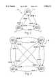
- FIG. 1is a state diagram for encoding two different input values into three output levels, according to a preferred embodiment of the present invention
- FIG. 2is a state diagram for encoding three different input values into four output levels, according to a preferred embodiment of the present invention
- FIG. 3is a state diagram for encoding four different input values into five output levels, according to a preferred embodiment of the present invention
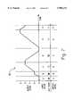
- FIG. 4is a timing diagram illustrating the encoding of four different input values according to the state diagram shown in FIG. 3;
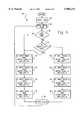
- FIG. 5is a flow chart illustrating a preferred embodiment of the algorithm for encoding the input values according to the state diagram shown in FIG. 3;
- FIG. 6is a flow chart illustrating a preferred embodiment of the algorithm for decoding output levels into input values
- FIG. 7is a timing diagram illustrating the encoding of four different input values
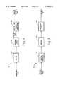
- FIG. 8is a block diagram of the hardware arrangement for implementing the encoding algorithm according to a preferred embodiment of the present invention.
- FIG. 9is a block diagram of the hardware arrangement for implementing the decoding algorithm according to a preferred embodiment of the present invention.
- the present inventionis directed to a system for encoding N input values into at least N+1 output levels.
- each output levelis represented by a different voltage.
- each output levelmay also be represented by a different frequency, phase, or amplitude.
- FIG. 1shows a state diagram 20 illustrating the transition between states for encoding two different input values (i.e., "0" and "1") into three output levels (i.e., output levels A, B and C), according to a preferred embodiment of the present invention.
- FIG. 2shows a state diagram 30 illustrating the transition between states for encoding three input values (i.e., "0,” “1” and “2") into four output levels (i.e., output levels A, B, C and D), according to a preferred embodiment of the present invention.
- FIG. 3shows a state diagram 40 illustrating the transitions between states for the encoding of four input values (i.e., "0,” “1,” “2” and “3") into five output levels (i.e., output levels A, B, C, D and E), according to a preferred embodiment of the present invention.
- each input valuemay represent a bit pair (i.e., "00,” “01,” “10,” and “11”). Therefore, each output level will represent two bits, rather than one bit, as in conventional encoding systems.
- each input valuecan represent log 2 (N) bits.
- the input valuesencode base 2 data (i.e., log 2 (N) bits) the input values may also encode base X data. Therefore, the input values may represent values O through X-1 in base X with the encoded output having at least X different output levels. It should also be understood that there may be more than N+1 output levels and transitions thereof for encoding N different input values. This allows for simplified implementation of various error detection and correction methods.
- FIG. 4provides a timing diagram 50 which shows the transition of the output levels as each input value is encoded.
- each input valuerepresents a bit pair.
- input value "0"represents bit pair “00”
- input value "1”represents bit pair “01”
- input value "2”represents bit pair “10”
- input value "3”represents bit pair "11.”
- each consecutive output levelwill be different.
- Each output level A thru Eis a discreet voltage level. For instance, output levels A thru E may correspond to voltages in the range of 0 to 5 volts.
- the input values shown in FIG. 4are encoded into output levels A thru E according to the algorithm shown in flow chart 60 of FIG. 5.
- a FIRST flagis set to TRUE. This will indicate that this is the first input value to be encoded.
- an input valuewill be read in.
- step 66it is determined whether the input value is the first input value to be encoded, by determining the status of the FIRST flag. If the input value is the first input value to be encoded, a first set of rules (steps 70-76) will be applied. If the input value is not the first input value to be encoded, it will be determined whether a second set of rules (steps 80-86) should be applied, as will be discussed below. For instance, in FIG.
- the first input valueis a "0" (corresponding to bit pair "00"). Accordingly, the conditions exist for applying the first set of rules. In particular, step 70 will be executed. En this respect, the output level will be set to A and the LAST variable will be set to "0.” The LAST variable is used as a reference value to determine the appropriate set of rules to be applied following the first input value, as will be described below in connection with step 68.
- step 90sets the FIRST flag to FALSE for the subsequent input values.
- the algorithmthen returns to step 64 to read in the next input value. In FIG. 4, the next consecutive input value is a "1.” Since the FIRST flag is now set to FALSE, the algorithm will proceed from step 66 to step 68.
- step 68it is determined whether the input value is less than the LAST variable. This step determines whether the first set of rules (steps 70-76) should be applied or whether the second set of rules (steps 80-86) should be applied.
- the algorithmwill apply the second set of rules (steps 80-86). Since the input value is "1," step 82 will be executed. Step 82 sets the output level to C and the LAST variable to 2. The algorithm then proceeds to step 90 and returns again to step 64 for reading in the next consecutive input value. The algorithm will continue in this manner until all of the input values have been encoded as output levels.
- the output level of the preceding encoded input valuewill determine the output level for the next consecutive encoded input value.
- the next consecutive input valuewill be encoded as one of the four remaining output levels.
- each of the 3'swill be encoded as different output levels.
- the output levelis E
- the second 3is encoded as output level D. Since no consecutive output level will be the same, the output levels will transition for each consecutive encoded input value.
- FIG. 6there is shown a flow chart 100 which illustrates an algorithm for decoding output levels back into input values, according to a preferred embodiment of the present invention.
- the FIRST flagis set to TRUE indicating that this is the first output level to be decoded.
- the output levelis read in.
- step 120the LAST variable will be set to the input value.
- the LAST variableis used to determine if an input value needs to be modified, as will be explained in connection with step 118. Proceeding next to step 122, the FIRST flag is set to FALSE for reading subsequent output levels. At step 124, the input value is stored. The algorithm now returns to step 104, to read in the next consecutive output level. After evaluating the output level at steps 106-114, if the FIRST flag is no longer true (step 116), the algorithm proceeds to step 118. At step 118, it is determined whether the input value (obtained at one of the steps 106-114) is greater than the LAST variable.
- the input valueis modified by decrementing it by one. If the input value is not greater than the LAST variable, then the input value is not modified. The algorithm then proceeds to step 120, where the LAST variable is set equal to the present input value, and step 122. At step 124, the input value is stored. The algorithm then returns to step 104 to read in the next consecutive output level. The algorithm will continue in this manner until all of the output levels have been decoded back to the original input values.
- each consecutive output level in the encoded waveformwill be different, and thus necessitate a transition.
- the decoding systemwill not require an external clocking signal to synchronize with the encoded waveform.
- the decoding systemis self-synchronizing with the encoded waveform by using the transition of each consecutive output level as the indicator that a new output level has been received for decoding.
- the decodercan be easily synchronized with an encoded waveform having a variable transmission speed.
- FIGS. 4-6show the implementation of only five output levels, the number of output levels may be significantly greater. As a result, the number of different input values may also be significantly greater. By increasing the number of output levels and input values, the number of bits represented by each input value can also be increased. Accordingly, as noted above, the present invention can be used to substantially increase the data transfer rate and conserve bandwidth.
- FIGS. 4-6illustrate a fixed timing relationship between one output level and the next solely for the purpose of illustrating the present invention.
- the time scale itselfis completely arbitrary, and the time required to transition from one output level to another is also completely arbitrary.
- the present inventioncan maximize the use of available bandwidth by varying the timing relationship from one transition to another. For example, in a bandwidth limited transmission medium, a change from one output level to a nearby output level, such as from A to B, will stabilize quickly, whereas a change from one output level to a distant output level, such as from A to E, will take longer to stabilize. Therefore, small changes can be transmitted more quickly.
- timing diagram 160which shows the timing where stabilization of the transitions varies depending upon the relative difference between consecutive output levels.
- the time for a single level changee.g., A to B
- the time needed for a change of two levelse.g., B to D.
- Arrangement 130is generally comprised of a buffer 132, encoding logic 134, and a digital-to-analog converter 136.
- buffer 132is a FIFO chip for buffering the received data.
- buffer 132may take the form of a Cyprus Semiconductor CY7C464.
- Encoding logic 134is programmed to implement the algorithm in the manner as described in connection with FIG. 5.
- encoding logic 134takes the form of an EPLD device, such as the Altera EPM7096S.
- Digital-to-analog converter 136may take the form of an 8-bit video DAC, such as the Phillips TDA8702.
- Arrangement 130operates in the following manner. Unencoded data is stored in buffer 132.
- the unencoded dataare input values which may represent one or more bits.
- Encoding logic 134reads out the unencoded data and encodes it into output levels transitions which are sent to digital-to-analog converter 136.
- the analog coded datamay be transmitted using a variety of different mediums, including a television signal. For instance, encoded data may be transmitted during the active video portion of the television signal. Accordingly, large quantities of data can be quickly and conveniently transferred.
- Arrangement 150is generally comprised of an analog-to-digital converter 152, a buffer 154 and decoding logic 156.
- Analog-to-digital converter 152is preferably an 8-bit video ADC, such as Phillips TDA8708B.
- buffer 154is a FIFO chip for buffering the digital data.
- buffer 154may take the form of a Cyprus Semiconductor CY7C464.
- Decoding logic 156is programmed to implement the algorithm in the manner as described in connection with FIG. 6.
- decoding logic 156takes the form of an EPLD device, such as the Altera EPM7096S.
- Arrangement 150operates in the following manner.
- Analog-to-digital converter 152receives the encoded output levels and converts them to digital data.
- Buffer 154stores the digital data.
- Decoding logic 156reads out the digital data from buffer 154 and decodes the encoded output level transitions into input values. These input values in turn may be converted to one or more bits.
Landscapes
- Engineering & Computer Science (AREA)
- Signal Processing (AREA)
- Multimedia (AREA)
- Computer Networks & Wireless Communication (AREA)
- Physics & Mathematics (AREA)
- Spectroscopy & Molecular Physics (AREA)
- Dc Digital Transmission (AREA)
Abstract
Description
Claims (15)
Priority Applications (9)
| Application Number | Priority Date | Filing Date | Title |
|---|---|---|---|
| US08/767,371US5903231A (en) | 1996-12-16 | 1996-12-16 | System for encoding base N data using a multi-level coding scheme |
| US08/898,314US6122010A (en) | 1996-12-16 | 1997-07-22 | Television signal data transmission system |
| JP52780498AJP2001506448A (en) | 1996-12-16 | 1997-12-11 | Multi-level coding |
| EP97951619AEP1018251A1 (en) | 1996-12-16 | 1997-12-11 | Multilevel coding |
| BR9713729-4ABR9713729A (en) | 1996-12-16 | 1997-12-11 | Multi-level encoding |
| CA002275185ACA2275185A1 (en) | 1996-12-11 | 1997-12-11 | Multilevel coding |
| PCT/US1997/022645WO1998027699A1 (en) | 1996-12-16 | 1997-12-11 | Multilevel coding |
| AU55212/98AAU5521298A (en) | 1996-12-16 | 1997-12-11 | Multilevel coding |
| MXPA99005610AMXPA99005610A (en) | 1996-12-16 | 1997-12-11 | Multilevel coding. |
Applications Claiming Priority (1)
| Application Number | Priority Date | Filing Date | Title |
|---|---|---|---|
| US08/767,371US5903231A (en) | 1996-12-16 | 1996-12-16 | System for encoding base N data using a multi-level coding scheme |
Related Child Applications (1)
| Application Number | Title | Priority Date | Filing Date |
|---|---|---|---|
| US08/898,314Continuation-In-PartUS6122010A (en) | 1996-12-16 | 1997-07-22 | Television signal data transmission system |
Publications (1)
| Publication Number | Publication Date |
|---|---|
| US5903231Atrue US5903231A (en) | 1999-05-11 |
Family
ID=25079276
Family Applications (1)
| Application Number | Title | Priority Date | Filing Date |
|---|---|---|---|
| US08/767,371Expired - LifetimeUS5903231A (en) | 1996-12-11 | 1996-12-16 | System for encoding base N data using a multi-level coding scheme |
Country Status (8)
| Country | Link |
|---|---|
| US (1) | US5903231A (en) |
| EP (1) | EP1018251A1 (en) |
| JP (1) | JP2001506448A (en) |
| AU (1) | AU5521298A (en) |
| BR (1) | BR9713729A (en) |
| CA (1) | CA2275185A1 (en) |
| MX (1) | MXPA99005610A (en) |
| WO (1) | WO1998027699A1 (en) |
Cited By (15)
| Publication number | Priority date | Publication date | Assignee | Title |
|---|---|---|---|---|
| US6122010A (en)* | 1996-12-16 | 2000-09-19 | Vidicast Ltd. | Television signal data transmission system |
| US20030095606A1 (en)* | 2001-11-16 | 2003-05-22 | Horowitz Mark A. | Method and apparatus for multi-level signaling |
| US20030235415A1 (en)* | 2002-06-21 | 2003-12-25 | Peters Frank H. | Optical communication devices and optical communication methods |
| US20040109509A1 (en)* | 2002-12-10 | 2004-06-10 | William Stonecypher | Technique for improving the quality of digital signals in a multi-level signaling system |
| US6961314B1 (en)* | 1998-10-30 | 2005-11-01 | Broadcom Corporation | Burst receiver for cable modem system |
| US20060015790A1 (en)* | 2004-07-16 | 2006-01-19 | Akash Bansal | Low overhead coding techniques |
| US20060088056A1 (en)* | 1998-10-30 | 2006-04-27 | Broadcom Corporation | Data packet fragmentation in a cable modem system |
| US20060126751A1 (en)* | 2004-12-10 | 2006-06-15 | Anthony Bessios | Technique for disparity bounding coding in a multi-level signaling system |
| US7139283B2 (en) | 1998-10-30 | 2006-11-21 | Broadcom Corporation | Robust techniques for optimal upstream communication between cable modem subscribers and a headend |
| US20070009018A1 (en)* | 2005-06-02 | 2007-01-11 | Yuanlong Wang | Signaling system |
| US7561808B2 (en)* | 2000-03-21 | 2009-07-14 | Lightwaves Systems, Inc. | System and method of using variable pulses for symbology |
| US20090273706A1 (en)* | 2008-05-02 | 2009-11-05 | Microsoft Corporation | Multi-level representation of reordered transform coefficients |
| US20110035225A1 (en)* | 2002-09-04 | 2011-02-10 | Microsoft Corporation | Entropy coding using escape codes to switch between plural code tables |
| US8406307B2 (en) | 2008-08-22 | 2013-03-26 | Microsoft Corporation | Entropy coding/decoding of hierarchically organized data |
| US8771307B2 (en) | 2007-06-29 | 2014-07-08 | Ethicon Endo-Surgery, Inc. | Duckbill seal with fluid drainage feature |
Families Citing this family (2)
| Publication number | Priority date | Publication date | Assignee | Title |
|---|---|---|---|---|
| JP5106757B2 (en)* | 2004-06-24 | 2012-12-26 | 三星電子株式会社 | Voltage level coding system and method |
| TWI752898B (en) | 2014-03-25 | 2022-01-21 | 日商新力股份有限公司 | Signaling devices and communication systems |
Citations (34)
| Publication number | Priority date | Publication date | Assignee | Title |
|---|---|---|---|---|
| US3634855A (en)* | 1969-05-05 | 1972-01-11 | Wendell S Miller | Self-clocking multilevel data coding system |
| US3743767A (en)* | 1971-10-04 | 1973-07-03 | Univ Illinois | Transmitter and receiver for the transmission of digital data over standard television channels |
| NL7310645A (en)* | 1973-08-01 | 1975-02-04 | Nederlanden Staat | Coding of binary signals into ternary signals - permits illegal codes to economise on check bits |
| US3984624A (en)* | 1974-07-25 | 1976-10-05 | Weston Instruments, Inc. | Video system for conveying digital and analog information |
| US4183054A (en)* | 1977-09-30 | 1980-01-08 | Harris Corporation | Digital, frequency-translated, plural-channel, vestigial sideband television communication system |
| US4244051A (en)* | 1978-01-20 | 1981-01-06 | Hitachi, Ltd. | Data communication method and apparatus therefor |
| US4484328A (en)* | 1981-08-03 | 1984-11-20 | Schlafly Hubert J | Television line multiplexed data communication system |
| US4538174A (en)* | 1982-03-11 | 1985-08-27 | Communications Patents Limited | Two-way subscriber TV system with multiple subscriber's sets |
| US4556973A (en)* | 1982-11-09 | 1985-12-03 | Pioneer Electronic Corp. | Frequency-division multiplex communication method and system |
| US4626913A (en)* | 1984-06-26 | 1986-12-02 | Rca Corporation | Chroma burst derived clock regenerator for teletext decoder |
| US4665431A (en)* | 1982-06-24 | 1987-05-12 | Cooper J Carl | Apparatus and method for receiving audio signals transmitted as part of a television video signal |
| US4750036A (en)* | 1986-05-14 | 1988-06-07 | Radio Telcom & Technology, Inc. | Interactive television and data transmission system |
| US4789895A (en)* | 1987-04-30 | 1988-12-06 | Gte Government Systems Corporation | System for synchronizing digital bit stream for telecommunication system |
| US4800428A (en)* | 1986-05-22 | 1989-01-24 | U.S. Philips Corporation | Circuit arrangement for a television receiver comprising a video text decoder |
| US4805020A (en)* | 1983-03-21 | 1989-02-14 | Greenberg Burton L | Television program transmission verification method and apparatus |
| US4807031A (en)* | 1987-10-20 | 1989-02-21 | Interactive Systems, Incorporated | Interactive video method and apparatus |
| US4910750A (en)* | 1985-12-05 | 1990-03-20 | Stc Plc | Data transmission system |
| US4920503A (en)* | 1988-05-27 | 1990-04-24 | Pc Connection, Inc. | Computer remote control through a video signal |
| US4958230A (en)* | 1989-08-11 | 1990-09-18 | General Electric Company | Method of transmitting auxiliary information in a television signal |
| US4969041A (en)* | 1988-09-23 | 1990-11-06 | Dubner Computer Systems, Inc. | Embedment of data in a video signal |
| US5014125A (en)* | 1989-05-05 | 1991-05-07 | Cableshare, Inc. | Television system for the interactive distribution of selectable video presentations |
| US5063446A (en)* | 1989-08-11 | 1991-11-05 | General Electric Company | Apparatus for transmitting auxiliary signal in a TV channel |
| US5075773A (en)* | 1987-12-07 | 1991-12-24 | British Broadcasting Corporation | Data transmission in active picture period |
| EP0490504A2 (en)* | 1990-12-12 | 1992-06-17 | Nortel Networks Corporation | Multilevel line coding scheme |
| US5177604A (en)* | 1986-05-14 | 1993-01-05 | Radio Telcom & Technology, Inc. | Interactive television and data transmission system |
| US5200822A (en)* | 1991-04-23 | 1993-04-06 | National Broadcasting Company, Inc. | Arrangement for and method of processing data, especially for identifying and verifying airing of television broadcast programs |
| US5243423A (en)* | 1991-12-20 | 1993-09-07 | A. C. Nielsen Company | Spread spectrum digital data transmission over TV video |
| US5251301A (en)* | 1988-05-27 | 1993-10-05 | Pc Connection, Inc. | Computer remote control through a video signal |
| WO1994009578A1 (en)* | 1992-10-16 | 1994-04-28 | Universitet I Linköping | An apparatus for transferring information from a first to a second electronic unit |
| US5327237A (en)* | 1991-06-14 | 1994-07-05 | Wavephore, Inc. | Transmitting data with video |
| US5387941A (en)* | 1991-06-14 | 1995-02-07 | Wavephore, Inc. | Data with video transmitter |
| US5410360A (en)* | 1991-06-14 | 1995-04-25 | Wavephore, Inc. | Timing control for injecting a burst and data into a video signal |
| US5452009A (en)* | 1993-12-29 | 1995-09-19 | Zenith Electronics Corp. | Digital transmission system with data rate optimized for noise in transmission medium |
| WO1996026607A1 (en)* | 1995-02-22 | 1996-08-29 | Hs-Cast S.R.L. | A system for transmitting data over a television channel |
- 1996
- 1996-12-16USUS08/767,371patent/US5903231A/ennot_activeExpired - Lifetime
- 1997
- 1997-12-11BRBR9713729-4Apatent/BR9713729A/ennot_activeIP Right Cessation
- 1997-12-11WOPCT/US1997/022645patent/WO1998027699A1/ennot_activeApplication Discontinuation
- 1997-12-11MXMXPA99005610Apatent/MXPA99005610A/ennot_activeApplication Discontinuation
- 1997-12-11EPEP97951619Apatent/EP1018251A1/ennot_activeWithdrawn
- 1997-12-11CACA002275185Apatent/CA2275185A1/ennot_activeAbandoned
- 1997-12-11AUAU55212/98Apatent/AU5521298A/ennot_activeAbandoned
- 1997-12-11JPJP52780498Apatent/JP2001506448A/enactivePending
Patent Citations (35)
| Publication number | Priority date | Publication date | Assignee | Title |
|---|---|---|---|---|
| US3634855A (en)* | 1969-05-05 | 1972-01-11 | Wendell S Miller | Self-clocking multilevel data coding system |
| US3743767A (en)* | 1971-10-04 | 1973-07-03 | Univ Illinois | Transmitter and receiver for the transmission of digital data over standard television channels |
| NL7310645A (en)* | 1973-08-01 | 1975-02-04 | Nederlanden Staat | Coding of binary signals into ternary signals - permits illegal codes to economise on check bits |
| US3984624A (en)* | 1974-07-25 | 1976-10-05 | Weston Instruments, Inc. | Video system for conveying digital and analog information |
| US4183054A (en)* | 1977-09-30 | 1980-01-08 | Harris Corporation | Digital, frequency-translated, plural-channel, vestigial sideband television communication system |
| US4244051A (en)* | 1978-01-20 | 1981-01-06 | Hitachi, Ltd. | Data communication method and apparatus therefor |
| US4484328A (en)* | 1981-08-03 | 1984-11-20 | Schlafly Hubert J | Television line multiplexed data communication system |
| US4538174A (en)* | 1982-03-11 | 1985-08-27 | Communications Patents Limited | Two-way subscriber TV system with multiple subscriber's sets |
| US4665431A (en)* | 1982-06-24 | 1987-05-12 | Cooper J Carl | Apparatus and method for receiving audio signals transmitted as part of a television video signal |
| US4556973A (en)* | 1982-11-09 | 1985-12-03 | Pioneer Electronic Corp. | Frequency-division multiplex communication method and system |
| US4805020A (en)* | 1983-03-21 | 1989-02-14 | Greenberg Burton L | Television program transmission verification method and apparatus |
| US4626913A (en)* | 1984-06-26 | 1986-12-02 | Rca Corporation | Chroma burst derived clock regenerator for teletext decoder |
| US4910750A (en)* | 1985-12-05 | 1990-03-20 | Stc Plc | Data transmission system |
| US5177604A (en)* | 1986-05-14 | 1993-01-05 | Radio Telcom & Technology, Inc. | Interactive television and data transmission system |
| US4750036A (en)* | 1986-05-14 | 1988-06-07 | Radio Telcom & Technology, Inc. | Interactive television and data transmission system |
| US4800428A (en)* | 1986-05-22 | 1989-01-24 | U.S. Philips Corporation | Circuit arrangement for a television receiver comprising a video text decoder |
| US4789895A (en)* | 1987-04-30 | 1988-12-06 | Gte Government Systems Corporation | System for synchronizing digital bit stream for telecommunication system |
| US4807031A (en)* | 1987-10-20 | 1989-02-21 | Interactive Systems, Incorporated | Interactive video method and apparatus |
| US5075773A (en)* | 1987-12-07 | 1991-12-24 | British Broadcasting Corporation | Data transmission in active picture period |
| US4920503A (en)* | 1988-05-27 | 1990-04-24 | Pc Connection, Inc. | Computer remote control through a video signal |
| US5251301A (en)* | 1988-05-27 | 1993-10-05 | Pc Connection, Inc. | Computer remote control through a video signal |
| US4969041A (en)* | 1988-09-23 | 1990-11-06 | Dubner Computer Systems, Inc. | Embedment of data in a video signal |
| US5014125A (en)* | 1989-05-05 | 1991-05-07 | Cableshare, Inc. | Television system for the interactive distribution of selectable video presentations |
| US4958230A (en)* | 1989-08-11 | 1990-09-18 | General Electric Company | Method of transmitting auxiliary information in a television signal |
| US5063446A (en)* | 1989-08-11 | 1991-11-05 | General Electric Company | Apparatus for transmitting auxiliary signal in a TV channel |
| EP0490504A2 (en)* | 1990-12-12 | 1992-06-17 | Nortel Networks Corporation | Multilevel line coding scheme |
| US5191330A (en)* | 1990-12-12 | 1993-03-02 | Northern Telecom Limited | Binary for penternary (five-level) encoding system |
| US5200822A (en)* | 1991-04-23 | 1993-04-06 | National Broadcasting Company, Inc. | Arrangement for and method of processing data, especially for identifying and verifying airing of television broadcast programs |
| US5327237A (en)* | 1991-06-14 | 1994-07-05 | Wavephore, Inc. | Transmitting data with video |
| US5387941A (en)* | 1991-06-14 | 1995-02-07 | Wavephore, Inc. | Data with video transmitter |
| US5410360A (en)* | 1991-06-14 | 1995-04-25 | Wavephore, Inc. | Timing control for injecting a burst and data into a video signal |
| US5243423A (en)* | 1991-12-20 | 1993-09-07 | A. C. Nielsen Company | Spread spectrum digital data transmission over TV video |
| WO1994009578A1 (en)* | 1992-10-16 | 1994-04-28 | Universitet I Linköping | An apparatus for transferring information from a first to a second electronic unit |
| US5452009A (en)* | 1993-12-29 | 1995-09-19 | Zenith Electronics Corp. | Digital transmission system with data rate optimized for noise in transmission medium |
| WO1996026607A1 (en)* | 1995-02-22 | 1996-08-29 | Hs-Cast S.R.L. | A system for transmitting data over a television channel |
Cited By (40)
| Publication number | Priority date | Publication date | Assignee | Title |
|---|---|---|---|---|
| US6122010A (en)* | 1996-12-16 | 2000-09-19 | Vidicast Ltd. | Television signal data transmission system |
| US20070036176A1 (en)* | 1998-10-30 | 2007-02-15 | Broadcom Corporation | Methods to compensate for noise in a wireless communication system |
| US7103065B1 (en) | 1998-10-30 | 2006-09-05 | Broadcom Corporation | Data packet fragmentation in a cable modem system |
| US7512154B2 (en) | 1998-10-30 | 2009-03-31 | Broadcom Corporation | Data packet fragmentation in a wireless communication system |
| US9301310B2 (en) | 1998-10-30 | 2016-03-29 | Broadcom Corporation | Robust techniques for upstream communication between subscriber stations and a base station |
| US7519082B2 (en) | 1998-10-30 | 2009-04-14 | Broadcom Corporation | Data packet fragmentation in a wireless communication system |
| US20070109995A1 (en)* | 1998-10-30 | 2007-05-17 | Broadcom Corporation | Compensating for noise in a wireless communication system |
| US6961314B1 (en)* | 1998-10-30 | 2005-11-01 | Broadcom Corporation | Burst receiver for cable modem system |
| US7139283B2 (en) | 1998-10-30 | 2006-11-21 | Broadcom Corporation | Robust techniques for optimal upstream communication between cable modem subscribers and a headend |
| US20060088056A1 (en)* | 1998-10-30 | 2006-04-27 | Broadcom Corporation | Data packet fragmentation in a cable modem system |
| US7843847B2 (en) | 1998-10-30 | 2010-11-30 | Broadcom Corporation | Compensating for noise in a wireless communication system |
| US20070086484A1 (en)* | 1998-10-30 | 2007-04-19 | Broadcom Corporation | Data packet fragmentation in a wireless communication system |
| US7821954B2 (en) | 1998-10-30 | 2010-10-26 | Broadcom Corporation | Methods to compensate for noise in a wireless communication system |
| US7120123B1 (en) | 1998-10-30 | 2006-10-10 | Broadcom Corporation | Pre-equalization technique for upstream communication between cable modem and headend |
| US7561808B2 (en)* | 2000-03-21 | 2009-07-14 | Lightwaves Systems, Inc. | System and method of using variable pulses for symbology |
| US7142612B2 (en) | 2001-11-16 | 2006-11-28 | Rambus, Inc. | Method and apparatus for multi-level signaling |
| US20030095606A1 (en)* | 2001-11-16 | 2003-05-22 | Horowitz Mark A. | Method and apparatus for multi-level signaling |
| US20030235415A1 (en)* | 2002-06-21 | 2003-12-25 | Peters Frank H. | Optical communication devices and optical communication methods |
| US20110035225A1 (en)* | 2002-09-04 | 2011-02-10 | Microsoft Corporation | Entropy coding using escape codes to switch between plural code tables |
| US8090574B2 (en)* | 2002-09-04 | 2012-01-03 | Microsoft Corporation | Entropy encoding and decoding using direct level and run-length/level context-adaptive arithmetic coding/decoding modes |
| US8712783B2 (en) | 2002-09-04 | 2014-04-29 | Microsoft Corporation | Entropy encoding and decoding using direct level and run-length/level context-adaptive arithmetic coding/decoding modes |
| US9390720B2 (en) | 2002-09-04 | 2016-07-12 | Microsoft Technology Licensing, Llc | Entropy encoding and decoding using direct level and run-length/level context-adaptive arithmetic coding/decoding modes |
| US7180958B2 (en) | 2002-12-10 | 2007-02-20 | Rambus Inc. | Technique for utilizing spare bandwidth resulting from the use of a transition-limiting code in a multi-level signaling system |
| US20040240580A1 (en)* | 2002-12-10 | 2004-12-02 | Anthony Bessios | Technique for utilizing spare bandwidth resulting from the use of a code in a multi-level signaling system |
| US7180957B2 (en) | 2002-12-10 | 2007-02-20 | Rambus Inc. | Technique for utilizing spare bandwidth resulting from the use of a transition-limiting code in a multi-level signaling system |
| US7180959B2 (en) | 2002-12-10 | 2007-02-20 | Rambus Inc. | Technique for utilizing spare bandwidth resulting from the use of a code in a multi-level signaling system |
| US20040109509A1 (en)* | 2002-12-10 | 2004-06-10 | William Stonecypher | Technique for improving the quality of digital signals in a multi-level signaling system |
| US20040109510A1 (en)* | 2002-12-10 | 2004-06-10 | Anthony Bessios | Technique for utilizing spare bandwidth resulting from the use of a transition-limiting code in a multi-level signaling system |
| US20040208257A1 (en)* | 2002-12-10 | 2004-10-21 | Anthony Bessios | Technique for utilizing spare bandwidth resulting from the use of a transition-limiting code in a multi-level signaling system |
| US7113550B2 (en) | 2002-12-10 | 2006-09-26 | Rambus Inc. | Technique for improving the quality of digital signals in a multi-level signaling system |
| US20060015790A1 (en)* | 2004-07-16 | 2006-01-19 | Akash Bansal | Low overhead coding techniques |
| US7302631B2 (en) | 2004-07-16 | 2007-11-27 | Rambus Inc. | Low overhead coding techniques |
| US20060126751A1 (en)* | 2004-12-10 | 2006-06-15 | Anthony Bessios | Technique for disparity bounding coding in a multi-level signaling system |
| US7656321B2 (en) | 2005-06-02 | 2010-02-02 | Rambus Inc. | Signaling system |
| US20070009018A1 (en)* | 2005-06-02 | 2007-01-11 | Yuanlong Wang | Signaling system |
| US8771307B2 (en) | 2007-06-29 | 2014-07-08 | Ethicon Endo-Surgery, Inc. | Duckbill seal with fluid drainage feature |
| US8179974B2 (en) | 2008-05-02 | 2012-05-15 | Microsoft Corporation | Multi-level representation of reordered transform coefficients |
| US9172965B2 (en) | 2008-05-02 | 2015-10-27 | Microsoft Technology Licensing, Llc | Multi-level representation of reordered transform coefficients |
| US20090273706A1 (en)* | 2008-05-02 | 2009-11-05 | Microsoft Corporation | Multi-level representation of reordered transform coefficients |
| US8406307B2 (en) | 2008-08-22 | 2013-03-26 | Microsoft Corporation | Entropy coding/decoding of hierarchically organized data |
Also Published As
| Publication number | Publication date |
|---|---|
| AU5521298A (en) | 1998-07-15 |
| JP2001506448A (en) | 2001-05-15 |
| EP1018251A1 (en) | 2000-07-12 |
| MXPA99005610A (en) | 2002-07-02 |
| BR9713729A (en) | 2002-01-15 |
| WO1998027699A1 (en) | 1998-06-25 |
| CA2275185A1 (en) | 1998-06-25 |
Similar Documents
| Publication | Publication Date | Title |
|---|---|---|
| US5903231A (en) | System for encoding base N data using a multi-level coding scheme | |
| US5461379A (en) | Digital coding technique which avoids loss of synchronization | |
| KR100303581B1 (en) | Data coding and decoding system | |
| US6064697A (en) | Pulse modulating method, pulse modulating equipment and pulse demodulating equipment | |
| US7653165B2 (en) | Pulse amplitude modulated system with reduced intersymbol interference | |
| US6084915A (en) | Signaling method having mixed-base shell map indices | |
| US20060126751A1 (en) | Technique for disparity bounding coding in a multi-level signaling system | |
| US5113401A (en) | Block coding scheme for fractional-bit transmission | |
| WO2002009300A3 (en) | Method and system for turbo encoding in adsl | |
| WO1988004116A1 (en) | Method and apparatus for equalization of data transmission system | |
| EP3306821B1 (en) | Methods of converting or reconverting a data signal and method and system for data transmission and/or data reception | |
| JPH04233347A (en) | Method and apparatus for generating signal | |
| JP2003324491A (en) | Multilevel fsk modulation system | |
| US6754282B1 (en) | DC-free run length constrained line coding with channel gain | |
| US6018548A (en) | System and method for compressing data in a communication channel utilizing time encoding | |
| US5418819A (en) | Transmitting apparatus and receiving apparatus based on phase modulation method | |
| JP2001069181A (en) | Digital data transmission method and apparatus for implementing the method | |
| US7469022B2 (en) | Methods and apparatus for symmetrical phase-shift keying | |
| KR100390582B1 (en) | Line code transmission using pulse width bit inversion | |
| JP3888220B2 (en) | Code point detection method | |
| JP2751632B2 (en) | Multi-level modulation / demodulation communication system and method | |
| KR20010096009A (en) | Modulation code for communication and multimedia | |
| JPH10107759A (en) | Data transmitter | |
| JPH0136294B2 (en) | ||
| JPS61227425A (en) | Multiplexing circuit |
Legal Events
| Date | Code | Title | Description |
|---|---|---|---|
| AS | Assignment | Owner name:VIDICAST LTD., OHIO Free format text:ASSIGNMENT OF ASSIGNORS INTEREST;ASSIGNOR:EMELKO GLENN A.;REEL/FRAME:009778/0606 Effective date:19990216 | |
| STCF | Information on status: patent grant | Free format text:PATENTED CASE | |
| FPAY | Fee payment | Year of fee payment:4 | |
| FPAY | Fee payment | Year of fee payment:8 | |
| AS | Assignment | Owner name:EMELKO, GLENN A., MR., OHIO Free format text:ASSIGNMENT OF ASSIGNORS INTEREST;ASSIGNOR:VIDICAST LTD.;REEL/FRAME:019930/0195 Effective date:20071009 | |
| FEPP | Fee payment procedure | Free format text:PAT HOLDER NO LONGER CLAIMS SMALL ENTITY STATUS, ENTITY STATUS SET TO UNDISCOUNTED (ORIGINAL EVENT CODE: STOL); ENTITY STATUS OF PATENT OWNER: LARGE ENTITY | |
| AS | Assignment | Owner name:ESCO TECHNOLOGIES HOLDING INC., MISSOURI Free format text:ASSIGNMENT OF ASSIGNORS INTEREST;ASSIGNOR:EMELKO, GLENN A;REEL/FRAME:020431/0820 Effective date:20080129 | |
| FPAY | Fee payment | Year of fee payment:12 | |
| AS | Assignment | Owner name:ESCO TECHNOLOGIES HOLDING LLC, MISSOURI Free format text:CHANGE OF NAME;ASSIGNOR:ESCO TECHNOLOGIES HOLDING INC.;REEL/FRAME:032140/0597 Effective date:20111231 | |
| AS | Assignment | Owner name:ACLARA TECHNOLOGIES LLC, MISSOURI Free format text:ASSIGNMENT OF ASSIGNORS INTEREST;ASSIGNOR:ESCO TECHNOLOGIES HOLDING LLC;REEL/FRAME:032160/0615 Effective date:20140206 | |
| AS | Assignment | Owner name:CERBERUS BUSINESS FINANCE, LLC, AS AGENT, NEW YORK Free format text:PATENT SECURITY AGREEMENT;ASSIGNOR:ACLARA TECHNOLOGIES LLC;REEL/FRAME:032554/0912 Effective date:20140328 | |
| AS | Assignment | Owner name:BMO HARRIS BANK N.A., ILLINOIS Free format text:SECURITY INTEREST;ASSIGNOR:ACLARA TECHNOLOGIES LLC;REEL/FRAME:032608/0055 Effective date:20140328 | |
| AS | Assignment | Owner name:PNC BANK, NATIONAL ASSOCIATION, PENNSYLVANIA Free format text:SECURITY INTEREST;ASSIGNORS:METER READINGS HOLDING, LLC;ACLARA TECHNOLOGIES LLC;ACLARA INTERNATIONAL LLC;REEL/FRAME:032712/0931 Effective date:20140418 | |
| AS | Assignment | Owner name:ACLARA TECHNOLOGIES, LLC, MISSOURI Free format text:RELEASE BY SECURED PARTY;ASSIGNOR:BMO HARRIS BANK, N.A.;REEL/FRAME:032715/0461 Effective date:20140418 | |
| AS | Assignment | Owner name:MORGAN STANLEY SENIOR FUNDING, INC., AS COLLATERAL Free format text:SECURITY AGREEMENT;ASSIGNORS:ACLARA TECHNOLOGIES LLC;ACLARA METERS LLC;REEL/FRAME:039872/0227 Effective date:20160829 Owner name:ACLARA METERS LLC F/K/A MRH METERS LLC, MISSOURI Free format text:RELEASE OF SECURITY INTEREST IN PATENTS;ASSIGNOR:CERBERUS BUSINESS FINANCE, LLC;REEL/FRAME:039880/0908 Effective date:20160829 Owner name:ACLARA TECHNOLOGIES LLC, MISSOURI Free format text:RELEASE OF SECURITY INTEREST IN PATENTS;ASSIGNOR:CERBERUS BUSINESS FINANCE, LLC;REEL/FRAME:039880/0908 Effective date:20160829 | |
| AS | Assignment | Owner name:ACLARA TECHNOLOGIES LLC, MISSOURI Free format text:RELEASE BY SECURED PARTY;ASSIGNOR:MORGAN STANLEY SENIOR FUNDING, INC.;REEL/FRAME:045245/0231 Effective date:20180202 Owner name:ACLARA METERS LLC, MISSOURI Free format text:RELEASE BY SECURED PARTY;ASSIGNOR:MORGAN STANLEY SENIOR FUNDING, INC.;REEL/FRAME:045245/0231 Effective date:20180202 | |
| AS | Assignment | Owner name:ACLARA TECHNOLOGIES LLC, MISSOURI Free format text:TERMINATION AND RELEASE OF PATENT SECURITY AGREEMENT;ASSIGNOR:PNC BANK, NATIONAL ASSOCIATION;REEL/FRAME:045502/0776 Effective date:20180202 |