US5902499A - Method and apparatus for machining material with a liquid-guided laser beam - Google Patents
Method and apparatus for machining material with a liquid-guided laser beamDownload PDFInfo
- Publication number
- US5902499A US5902499AUS08/750,130US75013097AUS5902499AUS 5902499 AUS5902499 AUS 5902499AUS 75013097 AUS75013097 AUS 75013097AUS 5902499 AUS5902499 AUS 5902499A
- Authority
- US
- United States
- Prior art keywords
- liquid
- nozzle
- intake opening
- laser
- laser beam
- Prior art date
- Legal status (The legal status is an assumption and is not a legal conclusion. Google has not performed a legal analysis and makes no representation as to the accuracy of the status listed.)
- Expired - Lifetime
Links
Images

Classifications
- G—PHYSICS
- G02—OPTICS
- G02B—OPTICAL ELEMENTS, SYSTEMS OR APPARATUS
- G02B6/00—Light guides; Structural details of arrangements comprising light guides and other optical elements, e.g. couplings
- G02B6/02—Optical fibres with cladding with or without a coating
- G02B6/032—Optical fibres with cladding with or without a coating with non solid core or cladding
- B—PERFORMING OPERATIONS; TRANSPORTING
- B23—MACHINE TOOLS; METAL-WORKING NOT OTHERWISE PROVIDED FOR
- B23K—SOLDERING OR UNSOLDERING; WELDING; CLADDING OR PLATING BY SOLDERING OR WELDING; CUTTING BY APPLYING HEAT LOCALLY, e.g. FLAME CUTTING; WORKING BY LASER BEAM
- B23K26/00—Working by laser beam, e.g. welding, cutting or boring
- B23K26/02—Positioning or observing the workpiece, e.g. with respect to the point of impact; Aligning, aiming or focusing the laser beam
- B23K26/06—Shaping the laser beam, e.g. by masks or multi-focusing
- B23K26/064—Shaping the laser beam, e.g. by masks or multi-focusing by means of optical elements, e.g. lenses, mirrors or prisms
- B23K26/0648—Shaping the laser beam, e.g. by masks or multi-focusing by means of optical elements, e.g. lenses, mirrors or prisms comprising lenses
- B—PERFORMING OPERATIONS; TRANSPORTING
- B23—MACHINE TOOLS; METAL-WORKING NOT OTHERWISE PROVIDED FOR
- B23K—SOLDERING OR UNSOLDERING; WELDING; CLADDING OR PLATING BY SOLDERING OR WELDING; CUTTING BY APPLYING HEAT LOCALLY, e.g. FLAME CUTTING; WORKING BY LASER BEAM
- B23K26/00—Working by laser beam, e.g. welding, cutting or boring
- B23K26/02—Positioning or observing the workpiece, e.g. with respect to the point of impact; Aligning, aiming or focusing the laser beam
- B23K26/06—Shaping the laser beam, e.g. by masks or multi-focusing
- B23K26/0665—Shaping the laser beam, e.g. by masks or multi-focusing by beam condensation on the workpiece, e.g. for focusing
- B—PERFORMING OPERATIONS; TRANSPORTING
- B23—MACHINE TOOLS; METAL-WORKING NOT OTHERWISE PROVIDED FOR
- B23K—SOLDERING OR UNSOLDERING; WELDING; CLADDING OR PLATING BY SOLDERING OR WELDING; CUTTING BY APPLYING HEAT LOCALLY, e.g. FLAME CUTTING; WORKING BY LASER BEAM
- B23K26/00—Working by laser beam, e.g. welding, cutting or boring
- B23K26/14—Working by laser beam, e.g. welding, cutting or boring using a fluid stream, e.g. a jet of gas, in conjunction with the laser beam; Nozzles therefor
- B23K26/1423—Working by laser beam, e.g. welding, cutting or boring using a fluid stream, e.g. a jet of gas, in conjunction with the laser beam; Nozzles therefor the flow carrying an electric current
- B—PERFORMING OPERATIONS; TRANSPORTING
- B23—MACHINE TOOLS; METAL-WORKING NOT OTHERWISE PROVIDED FOR
- B23K—SOLDERING OR UNSOLDERING; WELDING; CLADDING OR PLATING BY SOLDERING OR WELDING; CUTTING BY APPLYING HEAT LOCALLY, e.g. FLAME CUTTING; WORKING BY LASER BEAM
- B23K26/00—Working by laser beam, e.g. welding, cutting or boring
- B23K26/14—Working by laser beam, e.g. welding, cutting or boring using a fluid stream, e.g. a jet of gas, in conjunction with the laser beam; Nozzles therefor
- B23K26/146—Working by laser beam, e.g. welding, cutting or boring using a fluid stream, e.g. a jet of gas, in conjunction with the laser beam; Nozzles therefor the fluid stream containing a liquid
- G—PHYSICS
- G02—OPTICS
- G02B—OPTICAL ELEMENTS, SYSTEMS OR APPARATUS
- G02B1/00—Optical elements characterised by the material of which they are made; Optical coatings for optical elements
- G02B1/06—Optical elements characterised by the material of which they are made; Optical coatings for optical elements made of fluids in transparent cells
- Y—GENERAL TAGGING OF NEW TECHNOLOGICAL DEVELOPMENTS; GENERAL TAGGING OF CROSS-SECTIONAL TECHNOLOGIES SPANNING OVER SEVERAL SECTIONS OF THE IPC; TECHNICAL SUBJECTS COVERED BY FORMER USPC CROSS-REFERENCE ART COLLECTIONS [XRACs] AND DIGESTS
- Y10—TECHNICAL SUBJECTS COVERED BY FORMER USPC
- Y10T—TECHNICAL SUBJECTS COVERED BY FORMER US CLASSIFICATION
- Y10T83/00—Cutting
- Y10T83/04—Processes
- Y10T83/0591—Cutting by direct application of fluent pressure to work
- Y—GENERAL TAGGING OF NEW TECHNOLOGICAL DEVELOPMENTS; GENERAL TAGGING OF CROSS-SECTIONAL TECHNOLOGIES SPANNING OVER SEVERAL SECTIONS OF THE IPC; TECHNICAL SUBJECTS COVERED BY FORMER USPC CROSS-REFERENCE ART COLLECTIONS [XRACs] AND DIGESTS
- Y10—TECHNICAL SUBJECTS COVERED BY FORMER USPC
- Y10T—TECHNICAL SUBJECTS COVERED BY FORMER US CLASSIFICATION
- Y10T83/00—Cutting
- Y10T83/364—By fluid blast and/or suction
Definitions
- the inventionrelates to an arrangement and method for processing material with a laser beam that is guided by a liquid jet.
- the laser beamis focused with the aid of an optical element, for example a lens, on the material to be processed in order to generate the intensity necessary for the processing operation. Due to this necessary beam focusing, a processing was possible only at the location of the focus point or the area immediately surrounding it.
- an optical elementfor example a lens
- a method for cutting a material with a laser beamfor which this beam was coupled with a water jet that was directed toward the material to be cut and was guided within this water jet.
- the feeding of the beamis by way of a beam guide (fiber), one end of which projected into the water jet that was produced in a nozzle.
- the diameter of the water jetwas greater than that of the beam guide.
- the known arrangementhad the disadvantage that the water jet diameter could never be smaller than that of the beam guide.
- the inventionis based on the realization that the laser beam that is focused with the focusing optics into the nozzle range can heat up the liquid more or less strongly, depending on the intensity distribution.
- Liquid ranges with varied temperatures, a spatial temperature gradientnot only have a spatially specific density distribution, but also a spatial refractive index distribution. Meaning liquids with a spatial temperature gradient react optically as a lens and, as a rule, in the focusing cone of a focused laser beam as a dispersing lens.
- no focusing lensis installed in the wall opposite the nozzle intake, as is the case with EP-A 0 515 983, but only a window, which transmits the laser radiation without losses. Only this window, which is located almost directly above the nozzle intake, makes it possible to keep the liquid volume in the point of the focusing cone as small as possible and the flow speed as high as possible.
- the disintegration length of the liquid jetcan be varied by way of the pressure of the liquid before it enters the nozzle duct. However, causing a purposeful interference to the liquid immediately prior to the nozzle duct intake is more elegant. This can be done, for example, with a piezo element, which exerts pressure jolts of a predetermined frequency and amplitude onto the liquid. The length of the liquid jet then depends on these parameters. The adjustment of the liquid jet length is important particularly if the layers below the material to be processed must not be hit by the laser beam.
- the absorption of the above-named oil over a wide wave-length range of the radiationis lower than that of water, so that on the one hand the work length is no longer limited by the absorption in the liquid, and on the other hand, the effect of the thermal lens in front of the nozzle is avoided or strongly reduced. At the same time, this also provides a protective effect against corrosion during and after the processing of the work piece.
- Silicone oilshave a series of advantageous qualities for this type of material processing. Namely they have an excellent resistance to oxidation, hydrolysis and weathering. Also, they exhibit a chemical indifference that excludes a corrosion danger. Furthermore, they distinguish themselves by an extremely low combustibility as well as a high compressibility.
- the laser beam conducted in the liquid jetpermits parallel cut edges. This makes it possible to process larger material strengths, among other things with a lower material loss.
- the beam quality of the laserwhich among other things is made worse by the beam guidance in a beam guide, plays a subordinate role. This lowers the purchasing costs for the laser.
- a beam guide for guiding the beam from the laser source to a coupling place within the working modulealso solves all safety problems for the beam guidance by the user. For the conventional beam focusing with only one focusing system without liquid jet, the poorer beam quality would lead to an even shorter working length.
- the electrical charge of the liquid jetcan be used in that its deflection is caused by a neighboring electrical field.
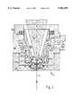
- FIG. 2longitudinal cut through the lower part of the processing module for the material processing arrangement, which has a nozzle for the liquid jet, wherein in this case the cross section of the liquid feed 35 relative to the nozzle block 43 is enlarged considerably for illustration purposes.
- FIG. 3longitudinal cut that is enlarged relative to FIG. 2, through the nozzle block of the nozzle as well as the liquid line that feeds the liquid without a retaining chamber.
- the material processing arrangement shown in FIG. 1has an ND:YAG laser 1 as radiation source, which emits a laser beam 3 with a wave length of 1.064 ⁇ m.
- the laser 1has capacity of 100 W in this case.
- this laser beam 3is coupled with a beam guide 6 with a standard core diameter of 100 ⁇ m to 600 ⁇ m, in this case 200 ⁇ m.
- the core diameter for the beam guide 6is selected in accordance with the radiation capacity that must be guided. For a 500 W laser, for example, it would be around 400 ⁇ m and for a 1 kW laser around 600 ⁇ m.
- the radiation guide 6is connected to a processing module 7 for the material processing, here also called a nozzle, that can be adjusted horizontally and in height. Owing to the fact that the radiation is conducted via the radiation guide 6, the laser 1 does not have to be arranged directly in the area of the work piece 9 to be processed or the processing module 7.
- the work piece 9 for processing, to be cut in this case,is arranged below the processing module 7.
- a catch basin 11 for catching the liquid from a liquid jet 12 which flows through a cut, for example produced here,is arranged below the work piece 9.
- the liquid to be caught in the catch basin 11is cleaned in a filter 15 that is connected via a line 13 with the catch basin 11 and is then fed into a reservoir 16, from which it can be recirculated to the processing module 7 by a pump 17 and via a line 19.
- the line 19is connected for safety reasons and for the pressure adjustment in the line 19 via an excess pressure valve 20 with reservoir 16.
- the processing module 7has a collimator 21 for collimating the laser beam that is advanced with the radiation guide 6, a nozzle block 43 with a nozzle duct 23 for forming the liquid jet 12 that is directed against the processing location 24 on the work piece 9, as well as a focusing lens 25 for focusing the collimated laser beam 27 into the plane 29 for the intake opening 30 at the location of the nozzle axis 31 for the nozzle duct 23 of the nozzle block 43, as shown in an enlarged view in FIG. 3.
- a disk-shaped liquid supply line 35exists above the nozzle intake opening 30 as liquid supply line.
- the liquid supply line 35does not have a liquid chamber functioning as retaining chamber in the area surrounding the nozzle intake opening 30.
- the edge 37 of the nozzle intake opening 30is designed such that it has sharp edges with a radius of less than 50 ⁇ m, preferably smaller than 5 ⁇ m. Owing to this sharp edge 37, the liquid jet separates from the upper nozzle edge 37, which has an air bolster 39 below it. Since air has a smaller refraction index than the normally used nozzle materials such as quartz or sapphire and the refraction index of air is also smaller than that of the silicone oil used as preferred liquid, the liquid jet 12 forms as a nearly ideal radiation guide. We want to point to the explanations in the introduction to the description with respect to the effects of the different refraction indices of nozzle material and liquid.
- the nozzle discharge opening 40is expanded relative to the intake opening 30, starting in the upper nozzle duct third 41 already. This expansion 42 avoids a swirling of the air bolster 39 that is located in the nozzle duct 23.
- the nozzle duct 23 of the "nozzle block 43" that forms the liquid jet 12is, as shown in FIG. 2, held in a nozzle block holder 46 with central borehole 45 for the liquid jet 12, which block is held in a bottom element 47 of the processing module 7.
- the seal on the sideis with a sealing ring (O-ring) 49.
- the line 19 supplying the liquidcan be flanged to a flange 50.
- the window 36is arranged in a center recess 51 of an insert 53.
- the sealing of the window 36 against the insert 53is also with a sealing ring 54. It can also be glued in.
- the insert 53has a conical inside area 55, the conical shape of which is adapted to the focusing cone 56 of the laser radiation that is to be focused with the focusing lens 25.
- the insert 53furthermore has an outside thread 57a, with which it is screwed into an inside thread 57b of a lower base element 59 of the processing module 7.
- the insert 53has several coaxially distributed, axial liquid ducts 61a and 61b, the width of which is selected such that the liquid can be transferred safely to the liquid supply line 35.
- the height of liquid supply line 35is adjusted through the screw-in depth of the insert 53.
- the liquid ducts 61a and 61bcould also be formed as slits originating from the outside thread 57a, contrary to the illustration in FIG. 2.
- the liquid ducts 61a and 61bare discharged via one each transitional duct 62a or 62b into a ring-shaped duct 63 that runs coaxially to the nozzle axis 31 inside the lower part of base element 59 and which is connected to flange 50.
- the insert 53is scaled off toward the top with another seal 65.
- the lower part 59 of the base elementcan be screwed into the base element of the processing module 7, which is not shown in detail, via the outside thread 66.
- the work piece 9 or the processing module 7preferably are moved only in steps. Each of the individual structural elements can then be cut one after the other with successive pulses.
Landscapes
- Physics & Mathematics (AREA)
- Optics & Photonics (AREA)
- Engineering & Computer Science (AREA)
- Plasma & Fusion (AREA)
- Mechanical Engineering (AREA)
- General Physics & Mathematics (AREA)
- Laser Beam Processing (AREA)
- Perforating, Stamping-Out Or Severing By Means Other Than Cutting (AREA)
Abstract
Description
1. Field of the Invention
The invention relates to an arrangement and method for processing material with a laser beam that is guided by a liquid jet.
2. Description of the Prior Art
Laser irradiation is used in a variety of ways for the material processing in the industry--cutting, drilling, welding, marking and material stripping. Nearly all types of material, e.g. steel, steel alloys, nonferrous metals, plastics and ceramics can be processed.
For nearly all of these methods, the laser beam is focused with the aid of an optical element, for example a lens, on the material to be processed in order to generate the intensity necessary for the processing operation. Due to this necessary beam focusing, a processing was possible only at the location of the focus point or the area immediately surrounding it.
From reference DE-A 36 43 284, a method for cutting a material with a laser beam is known, for which this beam was coupled with a water jet that was directed toward the material to be cut and was guided within this water jet. The feeding of the beam is by way of a beam guide (fiber), one end of which projected into the water jet that was produced in a nozzle. The diameter of the water jet was greater than that of the beam guide. The known arrangement had the disadvantage that the water jet diameter could never be smaller than that of the beam guide.
However, in order to achieve a high intensity at the processing location, a smallest possible beam diameter is necessary. The smaller the beam diameter, the lower the output of the laser radiation source with which it is possible to work. The smaller the output capacity of the laser, the lower the purchasing price.
Another disadvantage of the arrangement according to DE-A 36 43 284 resulted from the beam guide end that projected into the water jet. A dead water zone formed below the guide end which, among other things, produced interruptions in the flow that increased exponentially over the length of the water jet and finally resulted in a separation of the jet into drops. That is why it was impossible with this arrangement to achieve a laminar, compact beam length of more than 30 mm.
In the reference EP-A 0 515 983, an attempt was made to eliminate the above disadvantages by designing a water nozzle, which no longer contained the beam guide directly. In front of the nozzle that forms the water jet, there was a water chamber with a water intake and a focusing lens that closed off the chamber to the nozzle intake. This focusing lens is a component of an optical system, with which it was possible to focus the radiation emitted by the beam guide into the nozzle duct of the nozzle. The chamber was designed such that the water inside for the water jet was kept in a quasi standstill condition, that is in a relaxed condition.
However, it has proven that this second design variant of a laser beam to be coupled with a water jet causes uncontrollable damages to the nozzle wall in the area surrounding the nozzle duct intake.
It is the object of the invention to create an arrangement with which a laser beam can be coupled optimally with a fluid jet for material processing, without damage being caused to the nozzle that produces the fluid jet by the laser radiation.
The invention is based on the realization that the laser beam that is focused with the focusing optics into the nozzle range can heat up the liquid more or less strongly, depending on the intensity distribution. Liquid ranges with varied temperatures, a spatial temperature gradient, not only have a spatially specific density distribution, but also a spatial refractive index distribution. Meaning liquids with a spatial temperature gradient react optically as a lens and, as a rule, in the focusing cone of a focused laser beam as a dispersing lens.
An "optimally designed" coupling of the laser radiation with a liquid (water) jet produced in a nozzle duct, as shown in FIG. 2 of the EP-A 0 515 983, unfortunately does not work as assumed. For the arrangement as shown in the EP-A 0 515 983, a thermal lens formed in the range of the focusing cone point, above the nozzle duct intake, which moved the location of the focusing point shown there upwards, as well as increased the focusing diameter considerably. As a result of this, a portion of the laser radiation in the focusing cone hit the nozzle wall, in particular the nozzle surface that faces the liquid retaining chamber used there. As a result of the high intensity which is necessary for the material processing, the wall of the nozzle was consequently damaged.
With the design according to the EP-A 0 515 983, it was of disadvantage that the liquid used was water and the laser radiation was from a ND:YAG with 1.064 μm. This radiation exhibited especially in water an absorption quality that could not be ignored. The water in the range of the upper pyramid tip of the focused radiation (point range of the focusing cone) was heated according to the intensity distribution (high intensity in the axis and low intensity at the edges) and the above predicted thermal lens developed, which led to damage to the nozzle wall, in particular the nozzle surface in the range of the nozzle intake and in the final analysis led to the destruction of the nozzle that produces the liquid jet.
It was not only the use of water that decreased the degree of effectiveness of the coupling, but also the total structural design of the liquid chamber in front of the nozzle intake. Attempts were made, as is explained onpage 7, lines 32 ff and page 9, lines 41 ff, to achieve if possible a standstill in front of the nozzle intake. However, it is this standstill of the liquid that made possible or furthered the formation of the thermal lens. The liquid heated by (even by only a slight) radiation absorption was not removed as fast as possible so that it could not heat up any more, which would have reduced the lens formation effect. On the contrary, this increased heating up caused an even higher refraction for a thermal lens that formed.
However, the invention takes a different route. In this case, everything is done to prevent if possible the formation of a thermal lens or to strongly minimize its effect. The invention uses a liquid with the smallest possible absorption of the laser radiation used, namely silicone oil if the radiation is from the ND-YAG laser.
Furthermore, the structural design of the processing module that includes the nozzle arrangement and the focusing unit is selected such that even for a small radiation absorption that cannot be neglected, the effect of a thermal lens, insofar as it should occur at all, is at a minimum and thus can be neglected.
The invention suggests that the liquid from the range of the focusing cone for the laser radiation, in particular from the area surrounding the point, be removed as fast as possible to keep the heating up time as short as possible. The best results are of course achieved if the liquid remains only for a short time in the focusing cone with a low absorption.
In order to achieve the above conditions, the EP-A 0 515 983 with the liquid retaining chamber used there to hold the liquid at a standstill, which is propagated there, is avoided completely. The level of liquid feeding to the nozzle has approximately the diameter of the nozzle duct or is only slightly larger, simply to reduce the swirling of the flow.
Also, for a preferred design version, no focusing lens is installed in the wall opposite the nozzle intake, as is the case with EP-A 0 515 983, but only a window, which transmits the laser radiation without losses. Only this window, which is located almost directly above the nozzle intake, makes it possible to keep the liquid volume in the point of the focusing cone as small as possible and the flow speed as high as possible.
In another preferred embodiment, the fluid intake edge for the nozzle duct has a sharp edge design. As a result of this sharp edge, a liquid jet separation occurs at the intake edge with an air bolster between the liquid jet and the nozzle duct wall. Air has a smaller refraction index than the generally used nozzle materials such as quartz or sapphire. Also, the refraction index of air is smaller than that of the liquid to be used, meaning a liquid jet forms that functions as nearly ideal radiation guide. The laser radiation guided inside the liquid jet is thus "insulated" against the nozzle wall.
The air bolster proves itself in particular if the refraction index of the liquid jet guiding the radiation is smaller than the one for the nozzle because an outflowing of the radiation could then take place. If the refraction index for the liquid is bigger than the one for the nozzle material, then a total reflection occurs at the interface between the two mediums (liquid/nozzle wall), but the radiation enters the other material until it reaches the so-called penetration depth ("frustrated total internal reflection", "Goos-Hanchen-Shift"). If the nozzle material has an absorption coefficient that can no longer be neglected with the radiation used, then the air bolster here prevents a penetration of the radiation as well and thus also a damaging of the nozzle walls.
Thanks to the design of the air bolster, even materials that absorb the laser radiation can be used for the nozzle because the bolster keeps these away from the nozzle walls. Furthermore, an adjustment of the focusing cone to the nozzle duct axis is no longer absolutely necessary as a result of this because the radiation can no longer reach the nozzle duct walls due to the air bolster, even with a slight maladjustment. The angle for the focusing cone now can be selected such that it corresponds to the theoretical value for the numerical aperture of the liquid jet.
If, for example, the liquid is selected to be an oil from the group of silicone oils, e.g. a polydimethylsiloxane or a polymethylphenylsiloxane and quartz as nozzle material, then the refraction index of the liquid is higher than that of the nozzle material. The nozzle duct then has the quality of a beam guide, even if there is no air bolster. In that case, the length and shape of the nozzle duct is not critical for the beam guidance. It would even be possible to realize very long and bent nozzle ducts.
Of course it is possible to use other electrically conducting as well as in particular electrically non-conducting liquids in place of silicone oil. They must be selected such that their absorption for the laser wave length used remains within an acceptable frame in view of the flow speeds than can be achieved in the feed lines in the area of the nozzle in order to avoid a thermal lens. We want to point here especially to those types of liquids, which are used for liquid fibers as usable liquids.
The suggested arrangement permits liquid jet lengths of more than 200 mm. If an uninterrupted flow is ensured at the intake of the nozzle duct, the liquid pressure can be increased and the compact liquid jet length increased to a maximum, which depends above all on the liquid used and the nozzle diameter. Thus, for example, it follows that for water and a nozzle duct diameter of 150 μm, a maximum compact jet length of 150 mm for 80 bar liquid pressure results. If a silicone oil is used in place of water, then the compact liquid jet length can be increased to up to 500 mm. The length prior to the start of the "disintegration into drops" is referred to as compact liquid jet length. This disintegration into drops is based on unavoidable swirling, caused by the surrounding air as well as the surface tension.
The disintegration length of the liquid jet can be varied by way of the pressure of the liquid before it enters the nozzle duct. However, causing a purposeful interference to the liquid immediately prior to the nozzle duct intake is more elegant. This can be done, for example, with a piezo element, which exerts pressure jolts of a predetermined frequency and amplitude onto the liquid. The length of the liquid jet then depends on these parameters. The adjustment of the liquid jet length is important particularly if the layers below the material to be processed must not be hit by the laser beam.
Furthermore, the absorption of the above-named oil over a wide wave-length range of the radiation is lower than that of water, so that on the one hand the work length is no longer limited by the absorption in the liquid, and on the other hand, the effect of the thermal lens in front of the nozzle is avoided or strongly reduced. At the same time, this also provides a protective effect against corrosion during and after the processing of the work piece.
Silicone oils have a series of advantageous qualities for this type of material processing. Namely they have an excellent resistance to oxidation, hydrolysis and weathering. Also, they exhibit a chemical indifference that excludes a corrosion danger. Furthermore, they distinguish themselves by an extremely low combustibility as well as a high compressibility.
As a result of the long length of a liquid jet with nearly constant, high radiation intensity, a working length that is increased several times is obtained. This makes it possible, among other things, to process multilayer objects, e.g. objects consisting of two glass sheets with an air gap . . . , because the liquid jet conducting the high-energy laser radiation, which emerges from a cut joint or a hole for the most part retains its quality as beam guide.
An optimum coupling of the laser radiation is achieved if the focal point is placed in the plane for the nozzle opening. The underside for the laser radiation transmitting window, which faces the nozzle opening, should be at a distance of 200 μm to 500 μm for a nozzle diameter of 100 μm. This avoids a liquid retaining chamber that would favor the formation of a thermal lens.
In addition, the laser beam conducted in the liquid jet, permits parallel cut edges. This makes it possible to process larger material strengths, among other things with a lower material loss.
By coupling the laser beam with the liquid jet, the beam quality of the laser, which among other things is made worse by the beam guidance in a beam guide, plays a subordinate role. This lowers the purchasing costs for the laser. A beam guide for guiding the beam from the laser source to a coupling place within the working module also solves all safety problems for the beam guidance by the user. For the conventional beam focusing with only one focusing system without liquid jet, the poorer beam quality would lead to an even shorter working length.
The use of a beam guide, starting with the laser source, the small geometric dimensions of the coupling arrangement and the precise control that is no longer needed for a working distance between focusing unit and the surface of the work piece to be processed result in a simple displacement or sliding arrangement for the processing module.
The danger arising with the conventional beam focusing of having dirt on the focusing lens or a glass that protects this lens, caused by the spraying of material that is stripped from the work piece, are nonexistent here. Furthermore, the liquidity of the liquid jet ensures a very efficient cooling of the processing zone, so that no thermal stressing of the work piece along its processing edges can occur. For example, it is no longer possible for the material to pull out of shape when cutting small webs. In addition, this cooling leads only to a very slight hardening of the processing zone, which makes a reworking, e.g. an additional thread cutting, very simple.
A gas and dust development is avoided at the same time because the liquid bonds the stripped material. This eliminates the need for expensive exhaust air filtering systems.
Furthermore, melting occurrences are avoided or greatly reduced by the impacting liquid. The processing quality is very high. Also, it is possible to achieve protection against corrosion for corroding materials through a suitable selection of the liquid.
In a comparison with the known water jet cutting of work pieces, for which a water jet with mixed-in abrasive materials is used under considerably higher pressure relative to the above method according to the invention, a simple hydraulic system with flexible hydraulic lines can be used with the low pressure necessary for this method. This results in a simple slider system for the processing module. Furthermore, the strong wear of the nozzles, as it occurs with the water jet cutting, does not exist. Also, the slowing down of the liquid jet does not present any problems with the method according to the invention.
Water is the only liquid known from prior art for the liquid jet. Liquids other than water could be used only after liquid forming the liquid jet was captured, reprocessed and reused in particular in a closed circulation, for economic reasons.
After designing the liquid feed line or feed lines without liquid retaining chambers in the focusing channel tip area coordinated with the nozzle duct, it was determined that insofar as the nozzle material and also the liquid consist of electrically insulating material, an electrical charging of the liquid for the jet takes place. The charging results in voltages of more than 5 kV. If this electrically charged liquid jet is directed toward the material to be cut, it discharges its charge to this material. If, for example, copper or aluminum is processed with the radiation of an Nd:YAG laser coupled with a liquid jet, it can be determined that the material stripping rate strongly depends on the charge of the jet.
For a pulsed Nd:YAG laser radiation with 250 mJ, a pulse width of 0.1 ms and a liquid pressure of 10 bar, there is only a very slight material ablation. If the liquid pressure is increased to 100 bar, then an excellent stripping rate is achieved. This liquid jet with coupled-in laser radiation then produces a plasma on the material to be processed at a much faster rate because of its electrical charge, which increases the stripping rate. This effect can be increased even further by increasing the pressure to, for example, 1000 bar or by a directed electrical charging of the liquid in front of the nozzle intake.
Furthermore, the electrical charge of the liquid jet can be used in that its deflection is caused by a neighboring electrical field.
In the following, examples of the device according to the invention are explained in more detail with the aid of drawings. Advantages of the invention follow from the subsequent descriptive text.
FIG. 1 is a block diagram of a material processing device;
FIG. 2 longitudinal cut through the lower part of the processing module for the material processing arrangement, which has a nozzle for the liquid jet, wherein in this case the cross section of theliquid feed 35 relative to thenozzle block 43 is enlarged considerably for illustration purposes.
FIG. 3 longitudinal cut that is enlarged relative to FIG. 2, through the nozzle block of the nozzle as well as the liquid line that feeds the liquid without a retaining chamber.
The material processing arrangement shown in FIG. 1 has an ND:YAG laser 1 as radiation source, which emits alaser beam 3 with a wave length of 1.064 μm. Thelaser 1 has capacity of 100 W in this case. With the aid of a focusing unit 5, thislaser beam 3 is coupled with abeam guide 6 with a standard core diameter of 100 μm to 600 μm, in this case 200 μm. The core diameter for thebeam guide 6 is selected in accordance with the radiation capacity that must be guided. For a 500 W laser, for example, it would be around 400 μm and for a 1 kW laser around 600 μm. Theradiation guide 6 is connected to aprocessing module 7 for the material processing, here also called a nozzle, that can be adjusted horizontally and in height. Owing to the fact that the radiation is conducted via theradiation guide 6, thelaser 1 does not have to be arranged directly in the area of the work piece 9 to be processed or theprocessing module 7.
The work piece 9 for processing, to be cut in this case, is arranged below theprocessing module 7. Acatch basin 11 for catching the liquid from aliquid jet 12 which flows through a cut, for example produced here, is arranged below the work piece 9. The liquid to be caught in thecatch basin 11 is cleaned in afilter 15 that is connected via aline 13 with thecatch basin 11 and is then fed into areservoir 16, from which it can be recirculated to theprocessing module 7 by apump 17 and via aline 19. At the pump discharge, theline 19 is connected for safety reasons and for the pressure adjustment in theline 19 via anexcess pressure valve 20 withreservoir 16.
Theprocessing module 7 has acollimator 21 for collimating the laser beam that is advanced with theradiation guide 6, anozzle block 43 with anozzle duct 23 for forming theliquid jet 12 that is directed against the processing location 24 on the work piece 9, as well as a focusing lens 25 for focusing the collimatedlaser beam 27 into the plane 29 for the intake opening 30 at the location of the nozzle axis 31 for thenozzle duct 23 of thenozzle block 43, as shown in an enlarged view in FIG. 3. A disk-shapedliquid supply line 35 exists above the nozzle intake opening 30 as liquid supply line. Theliquid supply line 35 does not have a liquid chamber functioning as retaining chamber in the area surrounding the nozzle intake opening 30. The height forliquid supply line 35 should theoretically only have half the cross section of thenozzle duct 23. However, in order to reduce the frictional losses of the liquid in the pipe as well as to avoid swirling, this cross section was selected somewhat larger. Awindow 36 that is preferably coated with an antireflex material is inserted into the wall of theliquid supply line 35, above the nozzle intake opening 30, through which the laser radiation can be focused with the focusing lens 25 into the plane 29 of the intake opening 30 for thenozzle duct 23.
Theedge 37 of the nozzle intake opening 30 is designed such that it has sharp edges with a radius of less than 50 μm, preferably smaller than 5 μm. Owing to thissharp edge 37, the liquid jet separates from theupper nozzle edge 37, which has an air bolster 39 below it. Since air has a smaller refraction index than the normally used nozzle materials such as quartz or sapphire and the refraction index of air is also smaller than that of the silicone oil used as preferred liquid, theliquid jet 12 forms as a nearly ideal radiation guide. We want to point to the explanations in the introduction to the description with respect to the effects of the different refraction indices of nozzle material and liquid. The nozzle discharge opening 40 is expanded relative to the intake opening 30, starting in the upper nozzle duct third 41 already. Thisexpansion 42 avoids a swirling of the air bolster 39 that is located in thenozzle duct 23.
Thenozzle duct 23 of the "nozzle block 43" that forms theliquid jet 12 is, as shown in FIG. 2, held in a nozzle block holder 46 withcentral borehole 45 for theliquid jet 12, which block is held in abottom element 47 of theprocessing module 7. The seal on the side is with a sealing ring (O-ring) 49. Theline 19 supplying the liquid can be flanged to aflange 50.
Thewindow 36 is arranged in acenter recess 51 of an insert 53. The sealing of thewindow 36 against the insert 53 is also with a sealing ring 54. It can also be glued in. The insert 53 has a conical insidearea 55, the conical shape of which is adapted to the focusingcone 56 of the laser radiation that is to be focused with the focusing lens 25. The insert 53 furthermore has anoutside thread 57a, with which it is screwed into an inside thread 57b of alower base element 59 of theprocessing module 7. The insert 53 has several coaxially distributed,axial liquid ducts liquid supply line 35. The height ofliquid supply line 35 is adjusted through the screw-in depth of the insert 53. Theliquid ducts outside thread 57a, contrary to the illustration in FIG. 2. Theliquid ducts transitional duct 62a or 62b into a ring-shapedduct 63 that runs coaxially to the nozzle axis 31 inside the lower part ofbase element 59 and which is connected toflange 50. The insert 53 is scaled off toward the top with anotherseal 65. Thelower part 59 of the base element can be screwed into the base element of theprocessing module 7, which is not shown in detail, via theoutside thread 66.
Thebottom element 47 has an inside thread 67a, with which it can be screwed onto the outside thread 67b of thelower part 59 of the base element. Since the nozzle block holder 46 with thenozzle block 43 is only inserted into thebottom element 47, thenozzle block 43 can be exchanged quickly if, for example, aliquid jet 12 with another jet cross section must be used or it must be replaced.
In place of water and silicone oil, other liquids as well as (real or colloidal) solutions of materials can be used in accordance with the above-mentioned conditions.
In place of designing theliquid supply line 35 as a disk, it can also be produced as a conical shape with a sharp half-angle, wherein the angle point (cone point) comes to rest over the nozzle intake opening. Thewindow 36 in that case is no longer a plane parallel disk, but has a pyramid point at the side facing the nozzle intake and a spherical contour on the opposite side, in order to balance out the scattering effect of the pyramid point. This design results in a better flow against the nozzle intake.
When cutting sandwich structures, the work piece 9 or theprocessing module 7 preferably are moved only in steps. Each of the individual structural elements can then be cut one after the other with successive pulses.
Claims (17)
1. Method for processing material using a laser that emits a laser beam guided by a liquid jet comprised of liquid with a predetermined radiation absorption coefficient, with radiation from the laser beam being focussed in a focusing cone point range, the laser beam being directed at a nozzle having a nozzle duct provided with a nozzle intake opening disposed in a plane, the method comprising locating a radiation focusing point for coupling the laser beam into the liquid jet at the plane of the intake opening of the nozzle duct; conducting the liquid jet in an area surrounding the nozzle intake opening in the absence of a retaining chamber such that a flow speed for said liquid with said predetermined radiation absorption coefficient in the focusing cone point range of the radiation is sufficiently high that a formation of a thermal lens in the focusing point range is suppressed.
2. Method according to claim 1, including surrounding the liquid jet formed at the nozzle intake opening with an air bolster to thereby insulate the walls of the nozzle.
3. Method according to claim 1, including using silicone oil as the liquid jet, the silicon oil being from the group of polymethylsiloxane, and including using laser radiation with a wave length between 0.25 μm and 2.1 μm.
4. Method according to claim 1, including recovering liquid during material processing of the work piece, filtering the recovered liquid and returning the filtered liquid to the nozzle.
5. Method according to claim 1, wherein a laser beam emitted from the laser is guided by a laser beam guide located completely external of the liquid surrounding the nozzle intake opening.
6. Arrangement for processing material with a liquid jet comprising a laser for emitting a laser beam, and a processing module that includes a nozzle having a nozzle duct connected to a liquid supply line for forming a liquid jet comprised of liquid with a predetermined radiation absorption coefficient, the nozzle duct having an intake opening possessing a cross-sectional area and lying in an intake opening plane, an optical element for coupling the laser beam into the liquid jet, the optical element of the laser beam being focused in a focusing point range and into the intake opening plane of the nozzle duct, and the liquid supply line for the nozzle duct defining an area formed above the nozzle intake opening, the area above the nozzle intake opening having a height dimensioned relative to the cross-sectional area of the nozzle intake opening such that the area above the nozzle intake opening is absent a liquid retaining chamber, and a flow speed for said liquid with said predetermined radiation absorption coefficient in a focusing cone point range is sufficiently high that a formation of a thermal lens in the liquid in the focusing cone point range is suppressed.
7. Arrangement according to claim 6, wherein a wall of the liquid feed line is defined by a cover that is transparent to the laser radiation.
8. Arrangement according to claim 6, wherein the nozzle duct and the intake opening have surfaces that make contact with the liquid, said surfaces as well as the liquid being electrically insulating and the flow speed of the liquid in the area of the intake opening and the nozzle duct being selected high enough so that an electrical charge of the liquid jet takes place increase a material stripping rate.
9. Arrangement according to claim 6, wherein the nozzle duct includes a liquid intake edge, the liquid intake edge of the nozzle duct having a radius smaller than 50 μm.
10. Arrangement according to claim 6, wherein the nozzle includes a nozzle discharge opening that is expanded relative to the intake opening.
11. Arrangement according to claim 6, wherein the laser is spatially removed from the processing module, the arrangement further including a radiation guide for feeding laser radiation from the laser to the optical element.
12. Arrangement according to claim 6, wherein the liquid is a silicone oil from the group of polymethylsiloxane and laser radiation from the laser being in a wave length range between 0.25 μm and 2.1 μm.
13. Arrangement according to claim 6, including a catch basin for catching the liquid that flows through a work piece opening during material processing of the work piece or for catching the liquid that runs off the work piece, and a pump connected to a filtering unit for filtering the liquid from the catch basin and for pumping the liquid back to the nozzle duct.
14. Arrangement according to claim 6, including a coupling element for installing the processing module on a spatially movable adjustment unit.
15. Arrangement according to claim 6, further comprising a laser beam guide for the laser beam emitted from the laser, wherein no portion of the laser beam guide is located in the liquid supply line.
16. An arrangement for processing material with a liquid jet, comprising:
a laser for emitting a laser beam;
a processing module that includes a nozzle having a nozzle duct connected to a liquid supply line for forming a liquid jet of a liquid, the nozzle duct having an intake opening lying in an intake opening plane;
an optical element for coupling the laser beam into the liquid jet, the optical element being focused into the intake opening plane of the nozzle duct; and
means for sufficiently suppressing the formation of a thermal lens in the liquid such that no portion of radiation of the laser damages walls of the nozzle duct.
17. Arrangement according to claim 16, further comprising a laser beam guide for the laser beam emitted from the laser, wherein no portion of the laser beam guide is located in the liquid supply line.
Applications Claiming Priority (3)
| Application Number | Priority Date | Filing Date | Title |
|---|---|---|---|
| DE4418845ADE4418845C5 (en) | 1994-05-30 | 1994-05-30 | Method and device for material processing using a laser beam |
| DE4418845 | 1994-05-30 | ||
| PCT/IB1995/000390WO1995032834A1 (en) | 1994-05-30 | 1995-05-22 | Device for machining material with a laser |
Publications (1)
| Publication Number | Publication Date |
|---|---|
| US5902499Atrue US5902499A (en) | 1999-05-11 |
Family
ID=6519330
Family Applications (1)
| Application Number | Title | Priority Date | Filing Date |
|---|---|---|---|
| US08/750,130Expired - LifetimeUS5902499A (en) | 1994-05-30 | 1995-05-22 | Method and apparatus for machining material with a liquid-guided laser beam |
Country Status (5)
| Country | Link |
|---|---|
| US (1) | US5902499A (en) |
| EP (1) | EP0762947B1 (en) |
| JP (1) | JP3680864B2 (en) |
| DE (3) | DE4418845C5 (en) |
| WO (1) | WO1995032834A1 (en) |
Cited By (132)
| Publication number | Priority date | Publication date | Assignee | Title |
|---|---|---|---|---|
| US6118527A (en)* | 1998-02-09 | 2000-09-12 | Jurca Optoelektronik Gmbh | Method for monitoring the functionality of the transparent protective element of a transparent laser optical system, and a device for carrying out this method |
| EP1153697A3 (en)* | 2000-05-09 | 2003-01-02 | Shinko Electric Industries Co. Ltd. | Method and apparatus for cutting a semiconductor wafer |
| US20030062126A1 (en)* | 2001-10-03 | 2003-04-03 | Scaggs Michael J. | Method and apparatus for assisting laser material processing |
| US6563080B2 (en) | 2001-02-15 | 2003-05-13 | Scimed Life Systems, Inc. | Laser cutting of stents and other medical devices |
| US20030232488A1 (en)* | 2002-06-14 | 2003-12-18 | Chua Swee Kwang | Wafer level packaging |
| US20040004061A1 (en)* | 2002-07-03 | 2004-01-08 | Merdan Kenneth M. | Tubular cutting process and system |
| US20040004063A1 (en)* | 2002-07-08 | 2004-01-08 | Merdan Kenneth M. | Vertical stent cutting process |
| US6737606B2 (en) | 2001-09-10 | 2004-05-18 | Micron Technology, Inc. | Wafer dicing device and method |
| US20040140534A1 (en)* | 2002-12-12 | 2004-07-22 | Denso Corporation | Semiconductor device having passivation cap and method for manufacturing the same |
| KR100444582B1 (en)* | 2002-09-30 | 2004-08-16 | 삼성전자주식회사 | Fabrication method of ink jet print head using a liquid-jet guided laser |
| US6777647B1 (en) | 2003-04-16 | 2004-08-17 | Scimed Life Systems, Inc. | Combination laser cutter and cleaner |
| US20040221451A1 (en)* | 2003-05-06 | 2004-11-11 | Micron Technology, Inc. | Method for packaging circuits and packaged circuits |
| US20040259474A1 (en)* | 2003-04-18 | 2004-12-23 | Tdk Corporation | Magnetic head bar holding unit, lapping device, and method of lapping medium-opposing surface of thin-film magnetic head |
| US20050004616A1 (en)* | 2000-12-06 | 2005-01-06 | Medtronic, Inc. | Freeform substrates and devices |
| US20050160891A1 (en)* | 2004-01-28 | 2005-07-28 | Scimed Life Systems, Inc | Method of cutting material with hybrid liquid-jet/laser system |
| US20050193557A1 (en)* | 2004-03-03 | 2005-09-08 | Ko Sang-Cheol | Method of fabricating an ink-jet print head using a liquid-jet guided laser |
| US20050224473A1 (en)* | 2004-04-13 | 2005-10-13 | Kenneth Merdan | Inverted stent cutting process |
| US6960117B1 (en)* | 2004-04-28 | 2005-11-01 | Sae Magnetics (H.K.) Ltd. | Method to eliminate defects on the periphery of a slider due to conventional machining processes |
| US20060027542A1 (en)* | 2004-04-28 | 2006-02-09 | Niraj Mahadev | Method to eliminate defects on the periphery of a slider due to conventional machining processes |
| US20060084240A1 (en)* | 2001-10-08 | 2006-04-20 | Micron Technology, Inc. | Apparatus and method for packaging circuits |
| US7135039B2 (en) | 2000-03-06 | 2006-11-14 | Boston Scientific Scimed, Inc. | Intraluminar perforated radially expandable drug delivery prosthesis and a method for the production thereof |
| WO2007000039A1 (en)* | 2005-06-28 | 2007-01-04 | Gotohti.Com Inc. | Water jet guided laser disinfection |
| US20070025874A1 (en)* | 2005-07-26 | 2007-02-01 | Heiner Ophardt | Water jet guided laser disinfection |
| US20070119837A1 (en)* | 2005-11-30 | 2007-05-31 | Tokyo Electron Limited | Laser processing apparatus and laser processing method |
| EP1859890A1 (en) | 2005-03-18 | 2007-11-28 | Shibuya Kogyo Co., Ltd. | Hybrid laser processing system |
| US20070278195A1 (en)* | 2004-11-10 | 2007-12-06 | Synova Sa | Method and Device for Generating a Jet of Fluid for Material Processing and Fluid Nozzle for Use in Said Device |
| EP1918061A1 (en) | 2005-08-25 | 2008-05-07 | Shibuya Kogyo Co., Ltd. | Hybrid laser beam machining device |
| US20080105662A1 (en)* | 2003-07-09 | 2008-05-08 | Koichi Shigematsu | Laser beam processing method and laser beam processing machine |
| US20080182095A1 (en)* | 2006-11-06 | 2008-07-31 | Nitto Denko Corporation | Adhesive sheet for water jet laser dicing |
| US7476034B2 (en) | 2003-08-28 | 2009-01-13 | Boston Scientific Scimed, Inc. | Dynamic bushing for medical device tubing |
| US20090045177A1 (en)* | 2005-07-21 | 2009-02-19 | Ryoji Koseki | Hybrid Laser Processing Apparatus |
| CN101396768A (en)* | 2007-09-28 | 2009-04-01 | 速技能机械有限公司 | Laser processing device using laser beam induced into jet column |
| US20090084765A1 (en)* | 2007-09-28 | 2009-04-02 | Sugino Machine Limited | Laser machining apparatus using laser beam introduced into jet liquid column |
| US20090163991A1 (en)* | 2007-12-19 | 2009-06-25 | Boston Scientific Scimed, Inc. | Stent |
| US20090212020A1 (en)* | 2005-03-16 | 2009-08-27 | Fra Unhofer-Gesellschaft Zur Förderung Der Angewan | Method for Microstructuring Solid Surfaces |
| US20090227998A1 (en)* | 2008-03-06 | 2009-09-10 | Aquabeam Llc | Tissue ablation and cautery with optical energy carried in fluid stream |
| US20090311474A1 (en)* | 2007-04-20 | 2009-12-17 | Tomokazu Takahashi | Adhesive sheet for water jet laser dicing |
| EP2189236A1 (en) | 2008-11-21 | 2010-05-26 | Synova S.A. | Method and apparatus for improving reliability of a machining process |
| US20100173167A1 (en)* | 2007-04-30 | 2010-07-08 | Fraunhofer-Gesellschaft zur Förderung der angewandten Forschung e.V. | Method for producing thin layers and corresponding layer |
| EP2208568A1 (en) | 2009-01-20 | 2010-07-21 | Synova S.A. | Apparatus and method for processing material by means of laser |
| CN101823183A (en)* | 2009-03-04 | 2010-09-08 | 鸿富锦精密工业(深圳)有限公司 | Water-conducted laser device |
| US7850623B2 (en) | 2005-10-27 | 2010-12-14 | Boston Scientific Scimed, Inc. | Elongate medical device with continuous reinforcement member |
| US20110163078A1 (en)* | 2010-01-06 | 2011-07-07 | Denso Corporation | Device and method for machining workpiece with a laser beam |
| US8137293B2 (en) | 2009-11-17 | 2012-03-20 | Boston Scientific Scimed, Inc. | Guidewires including a porous nickel-titanium alloy |
| US20120074110A1 (en)* | 2008-08-20 | 2012-03-29 | Zediker Mark S | Fluid laser jets, cutting heads, tools and methods of use |
| DE102011102166A1 (en) | 2011-05-20 | 2012-11-22 | Fraunhofer-Gesellschaft zur Förderung der angewandten Forschung e.V. | Method for homogenizing the laser beam profile in processes using a liquid jet laser and corresponding device |
| US20120298649A1 (en)* | 2011-05-25 | 2012-11-29 | Sugino Machine Limited | Laser machining apparatus |
| CN103028847A (en)* | 2008-12-26 | 2013-04-10 | 株式会社电装 | Machining method and machining system for micromachining a part in a machine component |
| US8424617B2 (en) | 2008-08-20 | 2013-04-23 | Foro Energy Inc. | Methods and apparatus for delivering high power laser energy to a surface |
| CN103203543A (en)* | 2013-02-04 | 2013-07-17 | 中国航空工业集团公司北京航空制造工程研究所 | Method and device for injecting water restraint layer of laser shock processing blade |
| US8535243B2 (en) | 2008-09-10 | 2013-09-17 | Boston Scientific Scimed, Inc. | Medical devices and tapered tubular members for use in medical devices |
| US8551021B2 (en) | 2010-03-31 | 2013-10-08 | Boston Scientific Scimed, Inc. | Guidewire with an improved flexural rigidity profile |
| CN103358028A (en)* | 2013-07-16 | 2013-10-23 | 桂林电子科技大学 | Method and system for scribing brittle ultrathin piece by water jet and laser |
| US8571368B2 (en) | 2010-07-21 | 2013-10-29 | Foro Energy, Inc. | Optical fiber configurations for transmission of laser energy over great distances |
| US8627901B1 (en) | 2009-10-01 | 2014-01-14 | Foro Energy, Inc. | Laser bottom hole assembly |
| US8662160B2 (en) | 2008-08-20 | 2014-03-04 | Foro Energy Inc. | Systems and conveyance structures for high power long distance laser transmission |
| US20140076868A1 (en)* | 2012-09-14 | 2014-03-20 | General Electric Company | System and method for manufacturing an airfoil |
| US8684088B2 (en) | 2011-02-24 | 2014-04-01 | Foro Energy, Inc. | Shear laser module and method of retrofitting and use |
| US8720584B2 (en) | 2011-02-24 | 2014-05-13 | Foro Energy, Inc. | Laser assisted system for controlling deep water drilling emergency situations |
| EP2739429A2 (en) | 2011-08-02 | 2014-06-11 | Foro Energy Inc. | Laser systems and methods for the removal of structures |
| US8783360B2 (en) | 2011-02-24 | 2014-07-22 | Foro Energy, Inc. | Laser assisted riser disconnect and method of use |
| US8783361B2 (en) | 2011-02-24 | 2014-07-22 | Foro Energy, Inc. | Laser assisted blowout preventer and methods of use |
| US8795254B2 (en) | 2008-12-10 | 2014-08-05 | Boston Scientific Scimed, Inc. | Medical devices with a slotted tubular member having improved stress distribution |
| US8795202B2 (en) | 2011-02-04 | 2014-08-05 | Boston Scientific Scimed, Inc. | Guidewires and methods for making and using the same |
| US8809236B2 (en) | 2011-02-18 | 2014-08-19 | Oswald Elektromotoren Gmbh | Method for manufacturing a HTS coated tape with laser beam cutting |
| US8859988B1 (en)* | 2014-05-30 | 2014-10-14 | Jens Guenter Gaebelein | Method for coupling a laser beam into a liquid-jet |
| CN104174993A (en)* | 2013-05-23 | 2014-12-03 | 深圳市通发激光设备有限公司 | Laser-beam welding machine with device for automatically removing thermal lens effect of solid laser |
| US8969760B2 (en) | 2012-09-14 | 2015-03-03 | General Electric Company | System and method for manufacturing an airfoil |
| CN104526160A (en)* | 2014-11-13 | 2015-04-22 | 张立国 | Laser machining method and system |
| US9027668B2 (en) | 2008-08-20 | 2015-05-12 | Foro Energy, Inc. | Control system for high power laser drilling workover and completion unit |
| US20150165559A1 (en)* | 2013-12-13 | 2015-06-18 | Jens Guenter Gaebelein | Methods and apparatus to perform a liquid-jet guided laser process and to simplify the maintenance thereof |
| US9072874B2 (en) | 2011-05-13 | 2015-07-07 | Boston Scientific Scimed, Inc. | Medical devices with a heat transfer region and a heat sink region and methods for manufacturing medical devices |
| US9074422B2 (en) | 2011-02-24 | 2015-07-07 | Foro Energy, Inc. | Electric motor for laser-mechanical drilling |
| US9080425B2 (en) | 2008-10-17 | 2015-07-14 | Foro Energy, Inc. | High power laser photo-conversion assemblies, apparatuses and methods of use |
| US9085050B1 (en) | 2013-03-15 | 2015-07-21 | Foro Energy, Inc. | High power laser fluid jets and beam paths using deuterium oxide |
| US9089928B2 (en) | 2008-08-20 | 2015-07-28 | Foro Energy, Inc. | Laser systems and methods for the removal of structures |
| US9138786B2 (en) | 2008-10-17 | 2015-09-22 | Foro Energy, Inc. | High power laser pipeline tool and methods of use |
| CN105080752A (en)* | 2014-05-15 | 2015-11-25 | 罗伯特·博世有限公司 | Method and apparatus for focusing an output from an output port of an output device of a jet apparatus viscous medium |
| CN105143659A (en)* | 2013-04-23 | 2015-12-09 | 日立汽车系统株式会社 | Fuel injection valve and manufacturing method thereof |
| US9232960B2 (en) | 2007-01-02 | 2016-01-12 | Aquabeam, Llc | Minimally invasive devices for multi-fluid tissue ablation |
| US9244235B2 (en) | 2008-10-17 | 2016-01-26 | Foro Energy, Inc. | Systems and assemblies for transferring high power laser energy through a rotating junction |
| US9242309B2 (en) | 2012-03-01 | 2016-01-26 | Foro Energy Inc. | Total internal reflection laser tools and methods |
| US9267330B2 (en) | 2008-08-20 | 2016-02-23 | Foro Energy, Inc. | Long distance high power optical laser fiber break detection and continuity monitoring systems and methods |
| US9347271B2 (en) | 2008-10-17 | 2016-05-24 | Foro Energy, Inc. | Optical fiber cable for transmission of high power laser energy over great distances |
| US9360631B2 (en) | 2008-08-20 | 2016-06-07 | Foro Energy, Inc. | Optics assembly for high power laser tools |
| US9360643B2 (en) | 2011-06-03 | 2016-06-07 | Foro Energy, Inc. | Rugged passively cooled high power laser fiber optic connectors and methods of use |
| US9399269B2 (en) | 2012-08-02 | 2016-07-26 | Foro Energy, Inc. | Systems, tools and methods for high power laser surface decommissioning and downhole welding |
| US9468991B2 (en) | 2014-01-27 | 2016-10-18 | General Electric Company | Method determining hole completion |
| US9510853B2 (en) | 2009-03-06 | 2016-12-06 | Procept Biorobotics Corporation | Tissue resection and treatment with shedding pulses |
| CN106216837A (en)* | 2016-08-25 | 2016-12-14 | 南京先进激光技术研究院 | A kind of method of the multilayer material of separation by laser OCA optical cement laminating |
| US9562395B2 (en) | 2008-08-20 | 2017-02-07 | Foro Energy, Inc. | High power laser-mechanical drilling bit and methods of use |
| US20170120392A1 (en)* | 2015-10-30 | 2017-05-04 | Hypertherm, Inc. | Water Cooling of Laser Components |
| US9643282B2 (en) | 2014-10-17 | 2017-05-09 | Kennametal Inc. | Micro end mill and method of manufacturing same |
| US9659808B2 (en) | 2013-10-15 | 2017-05-23 | Mitsubishi Electric Corporation | Semiconductor-element manufacturing method and wafer mounting device using a vacuum end-effector |
| US9664012B2 (en) | 2008-08-20 | 2017-05-30 | Foro Energy, Inc. | High power laser decomissioning of multistring and damaged wells |
| US9662743B2 (en) | 2014-01-27 | 2017-05-30 | General Electric Company | Method for drilling a hole in an airfoil |
| US9669492B2 (en) | 2008-08-20 | 2017-06-06 | Foro Energy, Inc. | High power laser offshore decommissioning tool, system and methods of use |
| US9676058B2 (en) | 2014-01-27 | 2017-06-13 | General Electric Company | Method and system for detecting drilling progress in laser drilling |
| US20170182593A1 (en)* | 2014-06-16 | 2017-06-29 | Synova Sa | Machining head |
| US9719302B2 (en) | 2008-08-20 | 2017-08-01 | Foro Energy, Inc. | High power laser perforating and laser fracturing tools and methods of use |
| US9770785B2 (en) | 2014-11-18 | 2017-09-26 | General Electric Company | System and method for forming a cooling hole in an airfoil |
| US9776284B2 (en) | 2015-01-22 | 2017-10-03 | General Electric Company | System and method for cutting a passage in an airfoil |
| US9845652B2 (en) | 2011-02-24 | 2017-12-19 | Foro Energy, Inc. | Reduced mechanical energy well control systems and methods of use |
| US9895755B2 (en) | 2014-12-09 | 2018-02-20 | Kennametal Inc. | Cutting insert with internal coolant passages and method of making same |
| CN107876976A (en)* | 2017-12-20 | 2018-04-06 | 华中科技大学 | Liquid film jet guides laser processing device |
| US9962792B2 (en) | 2015-02-20 | 2018-05-08 | General Electric Company | Component repair using confined laser drilling |
| US10053967B2 (en) | 2008-08-20 | 2018-08-21 | Foro Energy, Inc. | High power laser hydraulic fracturing, stimulation, tools systems and methods |
| US10092980B1 (en)* | 2014-05-30 | 2018-10-09 | Avonisys Ag | Method for coupling a laser beam into a liquid-jet |
| US20180354072A1 (en)* | 2015-12-02 | 2018-12-13 | Avonisys Ag | Laser beam processing device comprising a coupling device for coupling a focused laser beam into a fluid jet |
| US10160059B2 (en) | 2016-03-03 | 2018-12-25 | General Electric Company | Decoupled liquid-jet guided laser nozzle cap |
| US10221687B2 (en) | 2015-11-26 | 2019-03-05 | Merger Mines Corporation | Method of mining using a laser |
| US10301912B2 (en)* | 2008-08-20 | 2019-05-28 | Foro Energy, Inc. | High power laser flow assurance systems, tools and methods |
| US10335900B2 (en) | 2016-03-03 | 2019-07-02 | General Electric Company | Protective shield for liquid guided laser cutting tools |
| RU2700340C1 (en)* | 2018-12-24 | 2019-09-16 | Федеральное государственное автономное научное учреждение "Центральный научно-исследовательский и опытно-конструкторский институт робототехники и технической кибернетики" (ЦНИИ РТК) | Laser-jet device |
| US10448966B2 (en) | 2010-02-04 | 2019-10-22 | Procept Biorobotics Corporation | Fluid jet tissue resection and cold coagulation methods |
| US10524822B2 (en) | 2009-03-06 | 2020-01-07 | Procept Biorobotics Corporation | Image-guided eye surgery apparatus |
| US10589385B2 (en) | 2015-01-08 | 2020-03-17 | General Electric Company | Method and system for confined laser drilling |
| US10653438B2 (en) | 2012-02-29 | 2020-05-19 | Procept Biorobotics Corporation | Automated image-guided tissue resection and treatment |
| RU2729253C1 (en)* | 2019-08-07 | 2020-08-05 | Федеральное государственное учреждение "Федеральный научно-исследовательский центр "Кристаллография и фотоника" Российской академии наук" | 3d microstructures formation method in optical materials |
| US11213313B2 (en) | 2013-09-06 | 2022-01-04 | Procept Biorobotics Corporation | Tissue resection and treatment with shedding pulses |
| US11253954B2 (en)* | 2015-09-30 | 2022-02-22 | Makino Milling Machine Co., Ltd. | Method for measuring inclination of waterjet of laser machining device |
| US11292081B2 (en) | 2015-01-08 | 2022-04-05 | General Electric Company | Method and system for confined laser drilling |
| US11298772B2 (en)* | 2018-09-26 | 2022-04-12 | Kabushiki Kaisha Toshiba | Welding apparatus and nozzle device |
| US11318560B2 (en) | 2015-07-28 | 2022-05-03 | Synova Sa | Process of treating a workpiece using a liquid jet guided laser beam |
| US20220134481A1 (en)* | 2019-01-22 | 2022-05-05 | Synova S.A. | Method and apparatus for cutting and ablating a workpiece with a complex fluid-jet-guided laser beam |
| US11406453B2 (en) | 2009-03-06 | 2022-08-09 | Procept Biorobotics Corporation | Physician controlled tissue resection integrated with treatment mapping of target organ images |
| US20220258282A1 (en)* | 2014-06-23 | 2022-08-18 | Synova Sa | Method for determining a position of a liquid jet |
| US11465238B2 (en)* | 2019-02-13 | 2022-10-11 | Bystronic Laser Ag | Gas guide, laser cutting head and laser cutting machine |
| US11590606B2 (en)* | 2008-08-20 | 2023-02-28 | Foro Energy, Inc. | High power laser tunneling mining and construction equipment and methods of use |
| US12054415B2 (en) | 2018-03-29 | 2024-08-06 | Corning Incorporated | Methods for laser processing rough transparent workpieces using pulsed laser beam focal lines and a fluid film |
| US12108964B2 (en) | 2007-01-02 | 2024-10-08 | Aquabeam, Llc | Minimally invasive tissue treatment device |
| US12440235B2 (en) | 2023-08-23 | 2025-10-14 | Procept Biorobotics Corporation | Automated image-guided tissue resection and treatment |
Families Citing this family (34)
| Publication number | Priority date | Publication date | Assignee | Title |
|---|---|---|---|---|
| GB9715014D0 (en)* | 1997-07-18 | 1997-09-24 | Secr Defence | Two phase cutting device |
| CN1134322C (en)* | 1998-04-30 | 2004-01-14 | 辛诺瓦有限公司 | Material shaping device with laser beam which is injected into stream of liquid |
| DE60041632D1 (en) | 2000-03-30 | 2009-04-09 | Nitto Denko Corp | Water-permeable adhesive tape for semiconductor processing |
| EP1269535B1 (en)* | 2000-04-04 | 2007-10-10 | Synova S.A. | Method for cutting an object and for further processing the cut material and a carrier for holding the object or the cut material |
| FR2810913A1 (en)* | 2000-06-29 | 2002-01-04 | Air Liquide | Laser cutting of low-alloy steels without oxide formation on the cut surfaces involves passing a jet of cryogenic fluid in the direction of the cutting line |
| US6765174B2 (en)* | 2001-02-05 | 2004-07-20 | Denso Corporation | Method for machining grooves by a laser and honeycomb structure forming die and method for producing the same die |
| DE10238339A1 (en)* | 2002-08-16 | 2004-03-04 | Universität Hannover | Method and device for laser beam processing |
| WO2005009267A1 (en)* | 2003-07-29 | 2005-02-03 | Koninklijke Philips Electronics N.V. | Device for delivering electromagnetic radiation to human tissue |
| EP1598140A1 (en) | 2004-05-19 | 2005-11-23 | Synova S.A. | Laser machining |
| WO2006010289A2 (en)* | 2004-07-30 | 2006-02-02 | Synova S.A. | Method for separating circuit units (chips) arranged on a semiconductor wafer |
| EP1940579B1 (en) | 2005-05-17 | 2010-06-23 | Technikus Ag | Method for material working by means of a laser guided in a water jet and device for carrying out said method |
| DE102006038001B3 (en)* | 2006-08-14 | 2008-03-27 | Fraunhofer-Gesellschaft zur Förderung der angewandten Forschung e.V. | Procedure for drying and/or dry holding of workpiece during fluid jet guidance processing of the workpiece, comprises supplying dry inert gas at a process head, which is conveyed nearly at the workpiece, whose processed area is dried |
| DE102010011580B4 (en) | 2010-03-16 | 2020-01-02 | Vollmer Werke Maschinenfabrik Gmbh | Device and method for measuring a liquid jet, in particular used as a light guide, and device for processing a workpiece |
| JP5740886B2 (en)* | 2010-09-22 | 2015-07-01 | 澁谷工業株式会社 | Laser processing equipment |
| DE102011107982A1 (en) | 2011-07-20 | 2013-01-24 | Rena Gmbh | Tool head (LCP head) |
| DE102012003202A1 (en) | 2012-02-17 | 2013-08-22 | Vollmer Werke Maschinenfabrik Gmbh | Device useful for processing workpieces, preferably blades by wet laser, comprises a base, machining unit movably mounted on base, which carries wet laser unit, and workpiece support, where wet laser unit comprises e.g. laser beam source |
| WO2013136411A1 (en) | 2012-03-12 | 2013-09-19 | 三菱電機株式会社 | Vacuum suction stage, semiconductor wafer dicing method, and semiconductor wafer annealing method |
| DE102012111797B4 (en) | 2012-12-05 | 2017-04-20 | Reinhard Caliebe | Machining device for a workpiece |
| DE102012111796B4 (en) | 2012-12-05 | 2017-04-20 | Reinhard Caliebe | Machining device for a workpiece |
| FR3002363B1 (en) | 2013-02-21 | 2015-03-20 | Andra | DECONTAMINATION PROCESS OF STEAM GENERATOR TUBES |
| CN103203545B (en)* | 2013-04-11 | 2015-05-13 | 中国科学院宁波材料技术与工程研究所 | Coupling method and device for water-jet-guided laser light path |
| JP6101139B2 (en)* | 2013-04-12 | 2017-03-22 | 株式会社東芝 | Laser processing method and laser processing apparatus |
| GB201419809D0 (en) | 2014-11-07 | 2014-12-24 | Element Six Technologies Ltd | A method of fabricating plates of super-hard material and cutting techniques suitable for such a method |
| DE102014225247A1 (en) | 2014-12-09 | 2016-06-09 | Robert Bosch Gmbh | Method for liquid jet cutting |
| JP6407740B2 (en)* | 2015-01-21 | 2018-10-17 | 株式会社ディスコ | Laser processing equipment |
| DE102016116512A1 (en) | 2016-09-03 | 2018-03-08 | Fraunhofer-Gesellschaft zur Förderung der angewandten Forschung e.V. | Method and device for machining a workpiece |
| EP3300833B1 (en) | 2016-10-03 | 2019-11-27 | Synova SA | Device for generating a jet of liquid |
| EP3513898A1 (en)* | 2018-01-19 | 2019-07-24 | Synova S.A. | Apparatus for automatic jet angle adjustment |
| RU2685306C1 (en)* | 2018-06-09 | 2019-04-17 | Акционерное общество "Высокотехнологический научно-исследовательский институт неорганических материалов имени академика А.А. Бочвара" | Device for laser material processing in a liquid medium |
| CN110227884A (en)* | 2019-05-08 | 2019-09-13 | 桂林电子科技大学 | Water Jet Guided Laser system of processing and method based on salt free ligands light path design |
| CN110142502A (en)* | 2019-05-15 | 2019-08-20 | 哈尔滨工业大学 | Water-guided laser generating device, water-guided laser processing system and processing method thereof |
| CN110883424B (en)* | 2019-11-22 | 2023-09-26 | 桂林电子科技大学 | Water-guided laser flexible micromachining system and method |
| EP4088855B1 (en)* | 2021-03-30 | 2024-01-31 | The Boeing Company | Laser module end effector for robotic device |
| AT527326B1 (en) | 2024-02-27 | 2025-01-15 | Aidexa Gmbh | Measuring device for optical scanning using water jet-guided light source irradiation |
Citations (11)
| Publication number | Priority date | Publication date | Assignee | Title |
|---|---|---|---|---|
| US3503804A (en)* | 1967-04-25 | 1970-03-31 | Hellmut Schneider | Method and apparatus for the production of sonic or ultrasonic waves on a surface |
| JPS56163090A (en)* | 1980-05-22 | 1981-12-15 | Toshiba Corp | Laser working equipment |
| JPS61245992A (en)* | 1985-04-24 | 1986-11-01 | Mitsubishi Electric Corp | Laser beam processing method |
| DE3643284A1 (en)* | 1986-12-18 | 1988-06-30 | Aesculap Ag | METHOD AND DEVICE FOR CUTTING A MATERIAL BY MEANS OF A LASER BEAM |
| JPS63188489A (en)* | 1987-01-30 | 1988-08-04 | Hitachi Ltd | Laser-assisted chemical processing equipment |
| JPH01316200A (en)* | 1988-06-14 | 1989-12-21 | Diesel Kiki Co Ltd | Processing device using liquid jet |
| WO1990002628A1 (en)* | 1988-09-01 | 1990-03-22 | Institut Fiziki Akademii Nauk Litovskoi Ssr | Method and device for making filters by laser machining |
| WO1990014195A1 (en)* | 1989-05-17 | 1990-11-29 | Fanuc Ltd | Cut-machining method by laser beam |
| EP0450313A2 (en)* | 1990-04-06 | 1991-10-09 | International Business Machines Corporation | Laser etching of materials in liquids |
| EP0515983A1 (en)* | 1991-05-28 | 1992-12-02 | Lasag Ag | Device for ablation of material, particularly used in dentistry |
| US5356081A (en)* | 1993-02-24 | 1994-10-18 | Electric Power Research Institute, Inc. | Apparatus and process for employing synergistic destructive powers of a water stream and a laser beam |
- 1994
- 1994-05-30DEDE4418845Apatent/DE4418845C5/ennot_activeExpired - Lifetime
- 1995
- 1995-05-18DEDE19518263Apatent/DE19518263A1/ennot_activeWithdrawn
- 1995-05-22WOPCT/IB1995/000390patent/WO1995032834A1/enactiveIP Right Grant
- 1995-05-22DEDE59510608Tpatent/DE59510608D1/ennot_activeExpired - Lifetime
- 1995-05-22USUS08/750,130patent/US5902499A/ennot_activeExpired - Lifetime
- 1995-05-22EPEP95917453Apatent/EP0762947B1/ennot_activeExpired - Lifetime
- 1995-05-22JPJP50060296Apatent/JP3680864B2/ennot_activeExpired - Lifetime
Patent Citations (12)
| Publication number | Priority date | Publication date | Assignee | Title |
|---|---|---|---|---|
| US3503804A (en)* | 1967-04-25 | 1970-03-31 | Hellmut Schneider | Method and apparatus for the production of sonic or ultrasonic waves on a surface |
| JPS56163090A (en)* | 1980-05-22 | 1981-12-15 | Toshiba Corp | Laser working equipment |
| JPS61245992A (en)* | 1985-04-24 | 1986-11-01 | Mitsubishi Electric Corp | Laser beam processing method |
| DE3643284A1 (en)* | 1986-12-18 | 1988-06-30 | Aesculap Ag | METHOD AND DEVICE FOR CUTTING A MATERIAL BY MEANS OF A LASER BEAM |
| US4952771A (en)* | 1986-12-18 | 1990-08-28 | Aesculap Ag | Process for cutting a material by means of a laser beam |
| JPS63188489A (en)* | 1987-01-30 | 1988-08-04 | Hitachi Ltd | Laser-assisted chemical processing equipment |
| JPH01316200A (en)* | 1988-06-14 | 1989-12-21 | Diesel Kiki Co Ltd | Processing device using liquid jet |
| WO1990002628A1 (en)* | 1988-09-01 | 1990-03-22 | Institut Fiziki Akademii Nauk Litovskoi Ssr | Method and device for making filters by laser machining |
| WO1990014195A1 (en)* | 1989-05-17 | 1990-11-29 | Fanuc Ltd | Cut-machining method by laser beam |
| EP0450313A2 (en)* | 1990-04-06 | 1991-10-09 | International Business Machines Corporation | Laser etching of materials in liquids |
| EP0515983A1 (en)* | 1991-05-28 | 1992-12-02 | Lasag Ag | Device for ablation of material, particularly used in dentistry |
| US5356081A (en)* | 1993-02-24 | 1994-10-18 | Electric Power Research Institute, Inc. | Apparatus and process for employing synergistic destructive powers of a water stream and a laser beam |
Cited By (242)
| Publication number | Priority date | Publication date | Assignee | Title |
|---|---|---|---|---|
| US6118527A (en)* | 1998-02-09 | 2000-09-12 | Jurca Optoelektronik Gmbh | Method for monitoring the functionality of the transparent protective element of a transparent laser optical system, and a device for carrying out this method |
| US20130004650A1 (en)* | 2000-03-06 | 2013-01-03 | Boston Scientific Scimed, Inc. | Intraluminar perforated radially expandable drug delivery prosthesis and a method for the production thereof |
| US8663317B2 (en)* | 2000-03-06 | 2014-03-04 | Boston Scientific Scimed, Inc. | Intraluminar perforated radially expandable drug delivery prosthesis and a method for the production thereof |
| US7135039B2 (en) | 2000-03-06 | 2006-11-14 | Boston Scientific Scimed, Inc. | Intraluminar perforated radially expandable drug delivery prosthesis and a method for the production thereof |
| US6583383B2 (en) | 2000-05-09 | 2003-06-24 | Shinko Electric Industries Co., Ltd. | Method and apparatus for cutting a semiconductor wafer |
| KR100720050B1 (en)* | 2000-05-09 | 2007-05-18 | 신꼬오덴기 고교 가부시키가이샤 | Method and apparatus for cutting a semiconductor wafer |
| EP1153697A3 (en)* | 2000-05-09 | 2003-01-02 | Shinko Electric Industries Co. Ltd. | Method and apparatus for cutting a semiconductor wafer |
| US7335530B2 (en)* | 2000-12-06 | 2008-02-26 | Medtronic, Inc. | Freeform substrates and devices |
| US20050004616A1 (en)* | 2000-12-06 | 2005-01-06 | Medtronic, Inc. | Freeform substrates and devices |
| US20030226833A1 (en)* | 2001-02-15 | 2003-12-11 | Scimed Life Systems, Inc. | Laser cutting of stents and other medical devices |
| US6563080B2 (en) | 2001-02-15 | 2003-05-13 | Scimed Life Systems, Inc. | Laser cutting of stents and other medical devices |
| US6867389B2 (en) | 2001-02-15 | 2005-03-15 | Scimed Life Systems, Inc. | Laser cutting of stents and other medical devices |
| US6737606B2 (en) | 2001-09-10 | 2004-05-18 | Micron Technology, Inc. | Wafer dicing device and method |
| US20040188400A1 (en)* | 2001-09-10 | 2004-09-30 | Micron Technology, Inc. | Wafer dicing device and method |
| US20070000875A1 (en)* | 2001-10-03 | 2007-01-04 | Coherent, Inc. | Method and apparatus for assisting laser material processing |
| US20030062126A1 (en)* | 2001-10-03 | 2003-04-03 | Scaggs Michael J. | Method and apparatus for assisting laser material processing |
| US20080054423A1 (en)* | 2001-10-08 | 2008-03-06 | Micron Technology, Inc. | Apparatus and method for packaging circuits |
| US8138617B2 (en) | 2001-10-08 | 2012-03-20 | Round Rock Research, Llc | Apparatus and method for packaging circuits |
| US8115306B2 (en) | 2001-10-08 | 2012-02-14 | Round Rock Research, Llc | Apparatus and method for packaging circuits |
| US20100140794A1 (en)* | 2001-10-08 | 2010-06-10 | Chia Yong Poo | Apparatus and method for packaging circuits |
| US20060084240A1 (en)* | 2001-10-08 | 2006-04-20 | Micron Technology, Inc. | Apparatus and method for packaging circuits |
| US7675169B2 (en) | 2001-10-08 | 2010-03-09 | Micron Technology, Inc. | Apparatus and method for packaging circuits |
| US7358154B2 (en) | 2001-10-08 | 2008-04-15 | Micron Technology, Inc. | Method for fabricating packaged die |
| US7375009B2 (en) | 2002-06-14 | 2008-05-20 | Micron Technology, Inc. | Method of forming a conductive via through a wafer |
| US8564106B2 (en) | 2002-06-14 | 2013-10-22 | Micron Technology, Inc. | Wafer level packaging |
| US20110018143A1 (en)* | 2002-06-14 | 2011-01-27 | Swee Kwang Chua | Wafer level packaging |
| US20030232488A1 (en)* | 2002-06-14 | 2003-12-18 | Chua Swee Kwang | Wafer level packaging |
| US8106488B2 (en) | 2002-06-14 | 2012-01-31 | Micron Technology, Inc. | Wafer level packaging |
| US20040004061A1 (en)* | 2002-07-03 | 2004-01-08 | Merdan Kenneth M. | Tubular cutting process and system |
| US20080275538A1 (en)* | 2002-07-03 | 2008-11-06 | Boston Scientific Scimed, Inc. | Tubular cutting process and system |
| US20050150100A1 (en)* | 2002-07-03 | 2005-07-14 | Merdan Kenneth M. | Tubular cutting process and system |
| US6888098B1 (en) | 2002-07-03 | 2005-05-03 | Scimed Life Systems, Inc. | Tubular cutting process and system |
| WO2004004966A1 (en)* | 2002-07-03 | 2004-01-15 | Boston Scientific Limited | Laser/fluid jet cutting process and system |
| US9180032B2 (en) | 2002-07-03 | 2015-11-10 | Boston Scientific Scimed, Inc. | Tubular cutting process and system |
| US20110036820A1 (en)* | 2002-07-08 | 2011-02-17 | Boston Scientific Scimed, Inc. | Vertical stent cutting process |
| US8044322B2 (en) | 2002-07-08 | 2011-10-25 | Boston Scientific Scimed, Inc. | Vertical stent cutting process |
| US20040004063A1 (en)* | 2002-07-08 | 2004-01-08 | Merdan Kenneth M. | Vertical stent cutting process |
| WO2004004964A1 (en)* | 2002-07-08 | 2004-01-15 | Boston Scientific Limited | Vertical stent cutting process and system |
| KR100444582B1 (en)* | 2002-09-30 | 2004-08-16 | 삼성전자주식회사 | Fabrication method of ink jet print head using a liquid-jet guided laser |
| US20040140534A1 (en)* | 2002-12-12 | 2004-07-22 | Denso Corporation | Semiconductor device having passivation cap and method for manufacturing the same |
| US6995466B2 (en) | 2002-12-12 | 2006-02-07 | Denso Corporation | Semiconductor device having passivation cap and method for manufacturing the same |
| US6777647B1 (en) | 2003-04-16 | 2004-08-17 | Scimed Life Systems, Inc. | Combination laser cutter and cleaner |
| US20040259474A1 (en)* | 2003-04-18 | 2004-12-23 | Tdk Corporation | Magnetic head bar holding unit, lapping device, and method of lapping medium-opposing surface of thin-film magnetic head |
| US9484225B2 (en) | 2003-05-06 | 2016-11-01 | Micron Technology, Inc. | Method for packaging circuits |
| US8555495B2 (en) | 2003-05-06 | 2013-10-15 | Micron Technology, Inc. | Method for packaging circuits |
| US10811278B2 (en) | 2003-05-06 | 2020-10-20 | Micron Technology, Inc. | Method for packaging circuits |
| US10453704B2 (en) | 2003-05-06 | 2019-10-22 | Micron Technology, Inc. | Method for packaging circuits |
| US20100146780A1 (en)* | 2003-05-06 | 2010-06-17 | Yong Poo Chia | Method for packaging circuits and packaged circuits |
| US8065792B2 (en) | 2003-05-06 | 2011-11-29 | Micron Technology, Inc. | Method for packaging circuits |
| US20040221451A1 (en)* | 2003-05-06 | 2004-11-11 | Micron Technology, Inc. | Method for packaging circuits and packaged circuits |
| US7712211B2 (en) | 2003-05-06 | 2010-05-11 | Micron Technology, Inc. | Method for packaging circuits and packaged circuits |
| US20080105662A1 (en)* | 2003-07-09 | 2008-05-08 | Koichi Shigematsu | Laser beam processing method and laser beam processing machine |
| US7476034B2 (en) | 2003-08-28 | 2009-01-13 | Boston Scientific Scimed, Inc. | Dynamic bushing for medical device tubing |
| US20050160891A1 (en)* | 2004-01-28 | 2005-07-28 | Scimed Life Systems, Inc | Method of cutting material with hybrid liquid-jet/laser system |
| US20050193557A1 (en)* | 2004-03-03 | 2005-09-08 | Ko Sang-Cheol | Method of fabricating an ink-jet print head using a liquid-jet guided laser |
| US8816244B2 (en) | 2004-04-13 | 2014-08-26 | Boston Scientific Scimed, Inc. | Inverted stent cutting process |
| US20050224473A1 (en)* | 2004-04-13 | 2005-10-13 | Kenneth Merdan | Inverted stent cutting process |
| US6960117B1 (en)* | 2004-04-28 | 2005-11-01 | Sae Magnetics (H.K.) Ltd. | Method to eliminate defects on the periphery of a slider due to conventional machining processes |
| US20060027542A1 (en)* | 2004-04-28 | 2006-02-09 | Niraj Mahadev | Method to eliminate defects on the periphery of a slider due to conventional machining processes |
| US20050245173A1 (en)* | 2004-04-28 | 2005-11-03 | Niraj Mahadev | Method to eliminate defects on the periphery of a slider due to conventional machining processes |
| US20070278195A1 (en)* | 2004-11-10 | 2007-12-06 | Synova Sa | Method and Device for Generating a Jet of Fluid for Material Processing and Fluid Nozzle for Use in Said Device |
| US10016845B2 (en)* | 2004-11-10 | 2018-07-10 | Synova Sa | Method and device for generating a jet of fluid for material processing and fluid nozzle for use in said device |
| CN101107092B (en)* | 2004-11-10 | 2013-03-27 | 辛诺瓦有限公司 | Method and device for generating a liquid jet for material processing and liquid nozzle for one such device |
| US20090212020A1 (en)* | 2005-03-16 | 2009-08-27 | Fra Unhofer-Gesellschaft Zur Förderung Der Angewan | Method for Microstructuring Solid Surfaces |
| EP1859890A4 (en)* | 2005-03-18 | 2012-08-08 | Shibuya Kogyo Co Ltd | Hybrid laser processing system |
| EP1859890A1 (en) | 2005-03-18 | 2007-11-28 | Shibuya Kogyo Co., Ltd. | Hybrid laser processing system |
| US20080169275A1 (en)* | 2005-03-18 | 2008-07-17 | Ryoji Koseki | Hybrid Laser Processing Apparatus |
| US7705266B2 (en)* | 2005-03-18 | 2010-04-27 | Shibuya Kogyo Co., Ltd. | Hybrid laser processing apparatus |
| WO2007000039A1 (en)* | 2005-06-28 | 2007-01-04 | Gotohti.Com Inc. | Water jet guided laser disinfection |
| US20090045177A1 (en)* | 2005-07-21 | 2009-02-19 | Ryoji Koseki | Hybrid Laser Processing Apparatus |
| US20070025874A1 (en)* | 2005-07-26 | 2007-02-01 | Heiner Ophardt | Water jet guided laser disinfection |
| US7910856B2 (en)* | 2005-08-25 | 2011-03-22 | Shibuya Kogyo Co., Ltd. | Hybrid laser processing apparatus |
| US20100108648A1 (en)* | 2005-08-25 | 2010-05-06 | Ryoji Koseki | Hybrid laser processing apparatus |
| EP1918061A1 (en) | 2005-08-25 | 2008-05-07 | Shibuya Kogyo Co., Ltd. | Hybrid laser beam machining device |
| EP1918061B1 (en)* | 2005-08-25 | 2012-05-16 | Shibuya Kogyo Co., Ltd. | Hybrid laser beam machining device |
| US8231551B2 (en) | 2005-10-27 | 2012-07-31 | Boston Scientific Scimed, Inc. | Elongate medical device with continuous reinforcement member |
| US7850623B2 (en) | 2005-10-27 | 2010-12-14 | Boston Scientific Scimed, Inc. | Elongate medical device with continuous reinforcement member |
| US7919727B2 (en)* | 2005-11-30 | 2011-04-05 | Tokyo Electron Limited | Laser processing apparatus and laser processing method |
| US20070119837A1 (en)* | 2005-11-30 | 2007-05-31 | Tokyo Electron Limited | Laser processing apparatus and laser processing method |
| US20080182095A1 (en)* | 2006-11-06 | 2008-07-31 | Nitto Denko Corporation | Adhesive sheet for water jet laser dicing |
| US9364250B2 (en) | 2007-01-02 | 2016-06-14 | Aquabeam, Llc | Minimally invasive devices for the treatment of prostate diseases |
| US11478269B2 (en) | 2007-01-02 | 2022-10-25 | Aquabeam, Llc | Minimally invasive methods for multi-fluid tissue ablation |
| US10251665B2 (en) | 2007-01-02 | 2019-04-09 | Aquabeam, Llc | Multi fluid tissue resection methods and devices |
| US10321931B2 (en) | 2007-01-02 | 2019-06-18 | Aquabeam, Llc | Minimally invasive methods for multi-fluid tissue ablation |
| US9232960B2 (en) | 2007-01-02 | 2016-01-12 | Aquabeam, Llc | Minimally invasive devices for multi-fluid tissue ablation |
| US11350964B2 (en) | 2007-01-02 | 2022-06-07 | Aquabeam, Llc | Minimally invasive treatment device for tissue resection |
| US9237902B2 (en) | 2007-01-02 | 2016-01-19 | Aquabeam, Llc | Multi-fluid tissue ablation methods for treatment of an organ |
| US9232959B2 (en) | 2007-01-02 | 2016-01-12 | Aquabeam, Llc | Multi fluid tissue resection methods and devices |
| US12290277B2 (en) | 2007-01-02 | 2025-05-06 | Aquabeam, Llc | Tissue resection with pressure sensing |
| US12108964B2 (en) | 2007-01-02 | 2024-10-08 | Aquabeam, Llc | Minimally invasive tissue treatment device |
| US20090311474A1 (en)* | 2007-04-20 | 2009-12-17 | Tomokazu Takahashi | Adhesive sheet for water jet laser dicing |
| US20100173167A1 (en)* | 2007-04-30 | 2010-07-08 | Fraunhofer-Gesellschaft zur Förderung der angewandten Forschung e.V. | Method for producing thin layers and corresponding layer |
| US8134098B2 (en)* | 2007-09-28 | 2012-03-13 | Sugino Machine Limited | Laser machining apparatus using laser beam introduced into jet liquid column |
| US20120152919A1 (en)* | 2007-09-28 | 2012-06-21 | Sugino Machine Limited | Laser Machining Apparatus Using Laser Beam Introduced into Jet Liquid Column |
| CN101396768A (en)* | 2007-09-28 | 2009-04-01 | 速技能机械有限公司 | Laser processing device using laser beam induced into jet column |
| US8581141B2 (en)* | 2007-09-28 | 2013-11-12 | Sugino Machine Limited | Laser machining apparatus using laser beam introduced into jet liquid column |
| CN101396768B (en)* | 2007-09-28 | 2013-07-24 | 速技能机械有限公司 | Laser processing device using laser beam induced into jet column |
| US20090084765A1 (en)* | 2007-09-28 | 2009-04-02 | Sugino Machine Limited | Laser machining apparatus using laser beam introduced into jet liquid column |
| US7722661B2 (en) | 2007-12-19 | 2010-05-25 | Boston Scientific Scimed, Inc. | Stent |
| US7922756B2 (en) | 2007-12-19 | 2011-04-12 | Boston Scientific Scimed, Inc. | Stent |
| US20100222868A1 (en)* | 2007-12-19 | 2010-09-02 | Boston Scientific Scimed, Inc. | Stent |
| US20110190873A1 (en)* | 2007-12-19 | 2011-08-04 | Boston Scientific Scimed, Inc. | Stent |
| US20090163991A1 (en)* | 2007-12-19 | 2009-06-25 | Boston Scientific Scimed, Inc. | Stent |
| US12102383B2 (en) | 2008-03-06 | 2024-10-01 | Aquabeam, Llc | Tissue resection device with motors and control circuitry |
| US11759258B2 (en) | 2008-03-06 | 2023-09-19 | Aquabeam, Llc | Controlled ablation with laser energy |
| US10342615B2 (en) | 2008-03-06 | 2019-07-09 | Aquabeam, Llc | Tissue ablation and cautery with optical energy carried in fluid stream |
| US12318137B2 (en) | 2008-03-06 | 2025-06-03 | Aquabeam, Llc | Controlled tissue treatment with energy and control circuitry |
| EP3622910A1 (en) | 2008-03-06 | 2020-03-18 | AquaBeam LLC | Tissue ablation and cautery with optical energy carried in fluid stream |
| US20090227998A1 (en)* | 2008-03-06 | 2009-09-10 | Aquabeam Llc | Tissue ablation and cautery with optical energy carried in fluid stream |
| US8814921B2 (en) | 2008-03-06 | 2014-08-26 | Aquabeam Llc | Tissue ablation and cautery with optical energy carried in fluid stream |
| US11033330B2 (en) | 2008-03-06 | 2021-06-15 | Aquabeam, Llc | Tissue ablation and cautery with optical energy carried in fluid stream |
| US11172986B2 (en) | 2008-03-06 | 2021-11-16 | Aquabeam Llc | Ablation with energy carried in fluid stream |
| US8869914B2 (en) | 2008-08-20 | 2014-10-28 | Foro Energy, Inc. | High power laser workover and completion tools and systems |
| US8936108B2 (en) | 2008-08-20 | 2015-01-20 | Foro Energy, Inc. | High power laser downhole cutting tools and systems |
| US8757292B2 (en) | 2008-08-20 | 2014-06-24 | Foro Energy, Inc. | Methods for enhancing the efficiency of creating a borehole using high power laser systems |
| US9562395B2 (en) | 2008-08-20 | 2017-02-07 | Foro Energy, Inc. | High power laser-mechanical drilling bit and methods of use |
| US8701794B2 (en) | 2008-08-20 | 2014-04-22 | Foro Energy, Inc. | High power laser perforating tools and systems |
| US11060378B2 (en)* | 2008-08-20 | 2021-07-13 | Foro Energy, Inc. | High power laser flow assurance systems, tools and methods |
| US10036232B2 (en) | 2008-08-20 | 2018-07-31 | Foro Energy | Systems and conveyance structures for high power long distance laser transmission |
| US9664012B2 (en) | 2008-08-20 | 2017-05-30 | Foro Energy, Inc. | High power laser decomissioning of multistring and damaged wells |
| US8424617B2 (en) | 2008-08-20 | 2013-04-23 | Foro Energy Inc. | Methods and apparatus for delivering high power laser energy to a surface |
| US11590606B2 (en)* | 2008-08-20 | 2023-02-28 | Foro Energy, Inc. | High power laser tunneling mining and construction equipment and methods of use |
| US20120074110A1 (en)* | 2008-08-20 | 2012-03-29 | Zediker Mark S | Fluid laser jets, cutting heads, tools and methods of use |
| US8820434B2 (en) | 2008-08-20 | 2014-09-02 | Foro Energy, Inc. | Apparatus for advancing a wellbore using high power laser energy |
| US8826973B2 (en) | 2008-08-20 | 2014-09-09 | Foro Energy, Inc. | Method and system for advancement of a borehole using a high power laser |
| US9669492B2 (en) | 2008-08-20 | 2017-06-06 | Foro Energy, Inc. | High power laser offshore decommissioning tool, system and methods of use |
| US9360631B2 (en) | 2008-08-20 | 2016-06-07 | Foro Energy, Inc. | Optics assembly for high power laser tools |
| US10053967B2 (en) | 2008-08-20 | 2018-08-21 | Foro Energy, Inc. | High power laser hydraulic fracturing, stimulation, tools systems and methods |
| US8662160B2 (en) | 2008-08-20 | 2014-03-04 | Foro Energy Inc. | Systems and conveyance structures for high power long distance laser transmission |
| US8511401B2 (en) | 2008-08-20 | 2013-08-20 | Foro Energy, Inc. | Method and apparatus for delivering high power laser energy over long distances |
| US9089928B2 (en) | 2008-08-20 | 2015-07-28 | Foro Energy, Inc. | Laser systems and methods for the removal of structures |
| US10301912B2 (en)* | 2008-08-20 | 2019-05-28 | Foro Energy, Inc. | High power laser flow assurance systems, tools and methods |
| US8636085B2 (en) | 2008-08-20 | 2014-01-28 | Foro Energy, Inc. | Methods and apparatus for removal and control of material in laser drilling of a borehole |
| US8997894B2 (en) | 2008-08-20 | 2015-04-07 | Foro Energy, Inc. | Method and apparatus for delivering high power laser energy over long distances |
| US9719302B2 (en) | 2008-08-20 | 2017-08-01 | Foro Energy, Inc. | High power laser perforating and laser fracturing tools and methods of use |
| US9027668B2 (en) | 2008-08-20 | 2015-05-12 | Foro Energy, Inc. | Control system for high power laser drilling workover and completion unit |
| US9284783B1 (en) | 2008-08-20 | 2016-03-15 | Foro Energy, Inc. | High power laser energy distribution patterns, apparatus and methods for creating wells |
| US9267330B2 (en) | 2008-08-20 | 2016-02-23 | Foro Energy, Inc. | Long distance high power optical laser fiber break detection and continuity monitoring systems and methods |
| US8535243B2 (en) | 2008-09-10 | 2013-09-17 | Boston Scientific Scimed, Inc. | Medical devices and tapered tubular members for use in medical devices |
| US9327810B2 (en) | 2008-10-17 | 2016-05-03 | Foro Energy, Inc. | High power laser ROV systems and methods for treating subsea structures |
| US9080425B2 (en) | 2008-10-17 | 2015-07-14 | Foro Energy, Inc. | High power laser photo-conversion assemblies, apparatuses and methods of use |
| US9138786B2 (en) | 2008-10-17 | 2015-09-22 | Foro Energy, Inc. | High power laser pipeline tool and methods of use |
| US9347271B2 (en) | 2008-10-17 | 2016-05-24 | Foro Energy, Inc. | Optical fiber cable for transmission of high power laser energy over great distances |
| US9244235B2 (en) | 2008-10-17 | 2016-01-26 | Foro Energy, Inc. | Systems and assemblies for transferring high power laser energy through a rotating junction |
| WO2010057328A1 (en) | 2008-11-21 | 2010-05-27 | Synova Sa | Method and apparatus for improving reliability of a machining process |
| US8946588B2 (en) | 2008-11-21 | 2015-02-03 | Synova Sa | Method and apparatus for improving reliability of a machining process |
| EP2189236A1 (en) | 2008-11-21 | 2010-05-26 | Synova S.A. | Method and apparatus for improving reliability of a machining process |
| US8795254B2 (en) | 2008-12-10 | 2014-08-05 | Boston Scientific Scimed, Inc. | Medical devices with a slotted tubular member having improved stress distribution |
| CN103028847A (en)* | 2008-12-26 | 2013-04-10 | 株式会社电装 | Machining method and machining system for micromachining a part in a machine component |
| CN103028847B (en)* | 2008-12-26 | 2015-10-28 | 株式会社电装 | For carrying out processing method and the system of processing of micromachined to the part on mechanical component |
| EP2208568A1 (en) | 2009-01-20 | 2010-07-21 | Synova S.A. | Apparatus and method for processing material by means of laser |
| CN101823183A (en)* | 2009-03-04 | 2010-09-08 | 鸿富锦精密工业(深圳)有限公司 | Water-conducted laser device |
| US10524822B2 (en) | 2009-03-06 | 2020-01-07 | Procept Biorobotics Corporation | Image-guided eye surgery apparatus |
| US11406453B2 (en) | 2009-03-06 | 2022-08-09 | Procept Biorobotics Corporation | Physician controlled tissue resection integrated with treatment mapping of target organ images |
| US9510853B2 (en) | 2009-03-06 | 2016-12-06 | Procept Biorobotics Corporation | Tissue resection and treatment with shedding pulses |
| US8627901B1 (en) | 2009-10-01 | 2014-01-14 | Foro Energy, Inc. | Laser bottom hole assembly |
| US8137293B2 (en) | 2009-11-17 | 2012-03-20 | Boston Scientific Scimed, Inc. | Guidewires including a porous nickel-titanium alloy |
| US20110163078A1 (en)* | 2010-01-06 | 2011-07-07 | Denso Corporation | Device and method for machining workpiece with a laser beam |
| US10448966B2 (en) | 2010-02-04 | 2019-10-22 | Procept Biorobotics Corporation | Fluid jet tissue resection and cold coagulation methods |
| US8551021B2 (en) | 2010-03-31 | 2013-10-08 | Boston Scientific Scimed, Inc. | Guidewire with an improved flexural rigidity profile |
| US8784337B2 (en) | 2010-03-31 | 2014-07-22 | Boston Scientific Scimed, Inc. | Catheter with an improved flexural rigidity profile |
| US8571368B2 (en) | 2010-07-21 | 2013-10-29 | Foro Energy, Inc. | Optical fiber configurations for transmission of laser energy over great distances |
| US8879876B2 (en) | 2010-07-21 | 2014-11-04 | Foro Energy, Inc. | Optical fiber configurations for transmission of laser energy over great distances |
| US8795202B2 (en) | 2011-02-04 | 2014-08-05 | Boston Scientific Scimed, Inc. | Guidewires and methods for making and using the same |
| US8809236B2 (en) | 2011-02-18 | 2014-08-19 | Oswald Elektromotoren Gmbh | Method for manufacturing a HTS coated tape with laser beam cutting |
| US8720584B2 (en) | 2011-02-24 | 2014-05-13 | Foro Energy, Inc. | Laser assisted system for controlling deep water drilling emergency situations |
| US8684088B2 (en) | 2011-02-24 | 2014-04-01 | Foro Energy, Inc. | Shear laser module and method of retrofitting and use |
| US8783360B2 (en) | 2011-02-24 | 2014-07-22 | Foro Energy, Inc. | Laser assisted riser disconnect and method of use |
| US8783361B2 (en) | 2011-02-24 | 2014-07-22 | Foro Energy, Inc. | Laser assisted blowout preventer and methods of use |
| US9845652B2 (en) | 2011-02-24 | 2017-12-19 | Foro Energy, Inc. | Reduced mechanical energy well control systems and methods of use |
| US9784037B2 (en) | 2011-02-24 | 2017-10-10 | Daryl L. Grubb | Electric motor for laser-mechanical drilling |
| US9074422B2 (en) | 2011-02-24 | 2015-07-07 | Foro Energy, Inc. | Electric motor for laser-mechanical drilling |
| US9291017B2 (en) | 2011-02-24 | 2016-03-22 | Foro Energy, Inc. | Laser assisted system for controlling deep water drilling emergency situations |
| US9072874B2 (en) | 2011-05-13 | 2015-07-07 | Boston Scientific Scimed, Inc. | Medical devices with a heat transfer region and a heat sink region and methods for manufacturing medical devices |
| DE102011102166A1 (en) | 2011-05-20 | 2012-11-22 | Fraunhofer-Gesellschaft zur Förderung der angewandten Forschung e.V. | Method for homogenizing the laser beam profile in processes using a liquid jet laser and corresponding device |
| WO2012159963A1 (en) | 2011-05-20 | 2012-11-29 | Fraunhofer-Gesellschaft zur Förderung der Angwandten Forschung E.V. | Method for homogenizing the laser beam profile in processes using a laser guided by a liquid jet and corresponding device |
| US10913131B2 (en)* | 2011-05-25 | 2021-02-09 | Sugino Machine Limited | Laser machining apparatus |
| US10668563B2 (en) | 2011-05-25 | 2020-06-02 | Sugino Machine Limited | Laser machining apparatus |
| US20120298649A1 (en)* | 2011-05-25 | 2012-11-29 | Sugino Machine Limited | Laser machining apparatus |
| US20170100798A1 (en)* | 2011-05-25 | 2017-04-13 | Sugino Machine Limited | Laser machining method |
| US9360643B2 (en) | 2011-06-03 | 2016-06-07 | Foro Energy, Inc. | Rugged passively cooled high power laser fiber optic connectors and methods of use |
| EP2739429A2 (en) | 2011-08-02 | 2014-06-11 | Foro Energy Inc. | Laser systems and methods for the removal of structures |
| US11464536B2 (en) | 2012-02-29 | 2022-10-11 | Procept Biorobotics Corporation | Automated image-guided tissue resection and treatment |
| US10653438B2 (en) | 2012-02-29 | 2020-05-19 | Procept Biorobotics Corporation | Automated image-guided tissue resection and treatment |
| US11737776B2 (en) | 2012-02-29 | 2023-08-29 | Procept Biorobotics Corporation | Automated image-guided tissue resection and treatment |
| US9242309B2 (en) | 2012-03-01 | 2016-01-26 | Foro Energy Inc. | Total internal reflection laser tools and methods |
| US9399269B2 (en) | 2012-08-02 | 2016-07-26 | Foro Energy, Inc. | Systems, tools and methods for high power laser surface decommissioning and downhole welding |
| US8969760B2 (en) | 2012-09-14 | 2015-03-03 | General Electric Company | System and method for manufacturing an airfoil |
| US8993923B2 (en)* | 2012-09-14 | 2015-03-31 | General Electric Company | System and method for manufacturing an airfoil |
| US20140076868A1 (en)* | 2012-09-14 | 2014-03-20 | General Electric Company | System and method for manufacturing an airfoil |
| CN103203543A (en)* | 2013-02-04 | 2013-07-17 | 中国航空工业集团公司北京航空制造工程研究所 | Method and device for injecting water restraint layer of laser shock processing blade |
| US9085050B1 (en) | 2013-03-15 | 2015-07-21 | Foro Energy, Inc. | High power laser fluid jets and beam paths using deuterium oxide |
| CN105143659A (en)* | 2013-04-23 | 2015-12-09 | 日立汽车系统株式会社 | Fuel injection valve and manufacturing method thereof |
| CN105143659B (en)* | 2013-04-23 | 2017-07-18 | 日立汽车系统株式会社 | Fuel injection valve and manufacturing method thereof |
| CN104174993A (en)* | 2013-05-23 | 2014-12-03 | 深圳市通发激光设备有限公司 | Laser-beam welding machine with device for automatically removing thermal lens effect of solid laser |
| CN103358028A (en)* | 2013-07-16 | 2013-10-23 | 桂林电子科技大学 | Method and system for scribing brittle ultrathin piece by water jet and laser |
| US11213313B2 (en) | 2013-09-06 | 2022-01-04 | Procept Biorobotics Corporation | Tissue resection and treatment with shedding pulses |
| US9659808B2 (en) | 2013-10-15 | 2017-05-23 | Mitsubishi Electric Corporation | Semiconductor-element manufacturing method and wafer mounting device using a vacuum end-effector |
| US10022820B2 (en)* | 2013-12-13 | 2018-07-17 | Avonisys Ag | Methods and apparatus to perform a liquid-jet guided laser process and to simplify the maintenance thereof |
| US20180318959A1 (en)* | 2013-12-13 | 2018-11-08 | Avonisys Ag | Methods and apparatus to perform a liquid-jet guided laser process and to simplify the maintenance thereof |
| US20150165559A1 (en)* | 2013-12-13 | 2015-06-18 | Jens Guenter Gaebelein | Methods and apparatus to perform a liquid-jet guided laser process and to simplify the maintenance thereof |
| US10940561B2 (en)* | 2013-12-13 | 2021-03-09 | Avonisys Ag | Methods and apparatus to perform a liquid-jet guided laser process and to simplify the maintenance thereof |
| US9662743B2 (en) | 2014-01-27 | 2017-05-30 | General Electric Company | Method for drilling a hole in an airfoil |
| US9468991B2 (en) | 2014-01-27 | 2016-10-18 | General Electric Company | Method determining hole completion |
| US9676058B2 (en) | 2014-01-27 | 2017-06-13 | General Electric Company | Method and system for detecting drilling progress in laser drilling |
| CN105080752A (en)* | 2014-05-15 | 2015-11-25 | 罗伯特·博世有限公司 | Method and apparatus for focusing an output from an output port of an output device of a jet apparatus viscous medium |
| US11260473B1 (en)* | 2014-05-30 | 2022-03-01 | Avonisys Ag | Method for coupling a laser beam into a liquid-jet |
| US10092980B1 (en)* | 2014-05-30 | 2018-10-09 | Avonisys Ag | Method for coupling a laser beam into a liquid-jet |
| US8859988B1 (en)* | 2014-05-30 | 2014-10-14 | Jens Guenter Gaebelein | Method for coupling a laser beam into a liquid-jet |
| US20170182593A1 (en)* | 2014-06-16 | 2017-06-29 | Synova Sa | Machining head |
| US10780527B2 (en)* | 2014-06-16 | 2020-09-22 | Synova Sa | Machining head |
| US20220258282A1 (en)* | 2014-06-23 | 2022-08-18 | Synova Sa | Method for determining a position of a liquid jet |
| US11350963B2 (en) | 2014-06-30 | 2022-06-07 | Procept Biorobotics Corporation | Fluid jet tissue ablation apparatus |
| US12053202B2 (en) | 2014-06-30 | 2024-08-06 | Procept Biorobotics Corporation | Tissue treatment with pulsatile shear waves |
| US9643282B2 (en) | 2014-10-17 | 2017-05-09 | Kennametal Inc. | Micro end mill and method of manufacturing same |
| CN104526160A (en)* | 2014-11-13 | 2015-04-22 | 张立国 | Laser machining method and system |
| CN104526160B (en)* | 2014-11-13 | 2016-09-07 | 张立国 | A kind of laser processing and laser-processing system |
| US9770785B2 (en) | 2014-11-18 | 2017-09-26 | General Electric Company | System and method for forming a cooling hole in an airfoil |
| US9895755B2 (en) | 2014-12-09 | 2018-02-20 | Kennametal Inc. | Cutting insert with internal coolant passages and method of making same |
| US11292081B2 (en) | 2015-01-08 | 2022-04-05 | General Electric Company | Method and system for confined laser drilling |
| US10589385B2 (en) | 2015-01-08 | 2020-03-17 | General Electric Company | Method and system for confined laser drilling |
| US9776284B2 (en) | 2015-01-22 | 2017-10-03 | General Electric Company | System and method for cutting a passage in an airfoil |
| US9962792B2 (en) | 2015-02-20 | 2018-05-08 | General Electric Company | Component repair using confined laser drilling |
| US11318560B2 (en) | 2015-07-28 | 2022-05-03 | Synova Sa | Process of treating a workpiece using a liquid jet guided laser beam |
| US11253954B2 (en)* | 2015-09-30 | 2022-02-22 | Makino Milling Machine Co., Ltd. | Method for measuring inclination of waterjet of laser machining device |
| US10525554B2 (en)* | 2015-10-30 | 2020-01-07 | Hypertherm, Inc. | Water cooling of laser components |
| US20170120392A1 (en)* | 2015-10-30 | 2017-05-04 | Hypertherm, Inc. | Water Cooling of Laser Components |
| US10221687B2 (en) | 2015-11-26 | 2019-03-05 | Merger Mines Corporation | Method of mining using a laser |
| US10933491B2 (en)* | 2015-12-02 | 2021-03-02 | Avonisys Ag | Laser beam processing device comprising a coupling device for coupling a focused laser beam into a fluid jet |
| US20180354072A1 (en)* | 2015-12-02 | 2018-12-13 | Avonisys Ag | Laser beam processing device comprising a coupling device for coupling a focused laser beam into a fluid jet |
| US10160059B2 (en) | 2016-03-03 | 2018-12-25 | General Electric Company | Decoupled liquid-jet guided laser nozzle cap |
| US10335900B2 (en) | 2016-03-03 | 2019-07-02 | General Electric Company | Protective shield for liquid guided laser cutting tools |
| CN106216837A (en)* | 2016-08-25 | 2016-12-14 | 南京先进激光技术研究院 | A kind of method of the multilayer material of separation by laser OCA optical cement laminating |
| CN107876976A (en)* | 2017-12-20 | 2018-04-06 | 华中科技大学 | Liquid film jet guides laser processing device |
| US12054415B2 (en) | 2018-03-29 | 2024-08-06 | Corning Incorporated | Methods for laser processing rough transparent workpieces using pulsed laser beam focal lines and a fluid film |
| US11298772B2 (en)* | 2018-09-26 | 2022-04-12 | Kabushiki Kaisha Toshiba | Welding apparatus and nozzle device |
| RU2700340C1 (en)* | 2018-12-24 | 2019-09-16 | Федеральное государственное автономное научное учреждение "Центральный научно-исследовательский и опытно-конструкторский институт робототехники и технической кибернетики" (ЦНИИ РТК) | Laser-jet device |
| US20220134481A1 (en)* | 2019-01-22 | 2022-05-05 | Synova S.A. | Method and apparatus for cutting and ablating a workpiece with a complex fluid-jet-guided laser beam |
| US12280449B2 (en)* | 2019-01-22 | 2025-04-22 | Synova S.A. | Method and apparatus for cutting and ablating a workpiece with a complex fluid-jet-guided laser beam |
| US11465238B2 (en)* | 2019-02-13 | 2022-10-11 | Bystronic Laser Ag | Gas guide, laser cutting head and laser cutting machine |
| RU2729253C1 (en)* | 2019-08-07 | 2020-08-05 | Федеральное государственное учреждение "Федеральный научно-исследовательский центр "Кристаллография и фотоника" Российской академии наук" | 3d microstructures formation method in optical materials |
| US12440235B2 (en) | 2023-08-23 | 2025-10-14 | Procept Biorobotics Corporation | Automated image-guided tissue resection and treatment |
Also Published As
| Publication number | Publication date |
|---|---|
| DE59510608D1 (en) | 2003-04-30 |
| DE4418845C5 (en) | 2012-01-05 |
| WO1995032834A1 (en) | 1995-12-07 |
| EP0762947A1 (en) | 1997-03-19 |
| EP0762947B1 (en) | 2003-03-26 |
| DE4418845C1 (en) | 1995-09-28 |
| JP3680864B2 (en) | 2005-08-10 |
| JPH10500903A (en) | 1998-01-27 |
| DE19518263A1 (en) | 1995-12-07 |
Similar Documents
| Publication | Publication Date | Title |
|---|---|---|
| US5902499A (en) | Method and apparatus for machining material with a liquid-guided laser beam | |
| CA2330426C (en) | Material shaping device with a laser beam which is injected into a stream of liquid | |
| US11219968B2 (en) | Laser processing head with two nozzles and systems and methods therefor | |
| JP5579733B2 (en) | Method and apparatus for improving the reliability of machining processes | |
| US8581141B2 (en) | Laser machining apparatus using laser beam introduced into jet liquid column | |
| US6175096B1 (en) | Method of processing a material by means of a laser beam | |
| CN101396768B (en) | Laser processing device using laser beam induced into jet column | |
| CN109989060B (en) | Coaxial powder feeding high-speed laser spraying device | |
| CN106312302B (en) | A self-focusing laser processing device | |
| CN112276346B (en) | Automatic accurate focusing processing head of super high power laser cutting | |
| JP3871240B2 (en) | Hybrid processing equipment | |
| CN211445900U (en) | Laser cladding head for inner wall of cylinder | |
| CN110142502A (en) | Water-guided laser generating device, water-guided laser processing system and processing method thereof | |
| CN110125540A (en) | A kind of method, system and its equipment of water guiding laser processing workpiece | |
| US7671296B2 (en) | Nose-piece for a laser-beam drilling or machining head | |
| CN113894444B (en) | Water guide pulse laser processing system and method based on interference light path design | |
| CN204545723U (en) | A kind of Rotary Water leads laser-processing system | |
| CN105772955A (en) | Device and method for improving taper of through hole through liquid scattering | |
| JP2006218544A (en) | Hybrid machining device and method | |
| CN102939182B (en) | Method and laser aid for dialysis workpiece | |
| CN219402786U (en) | Liquid guide laser coupling device | |
| CN117047298A (en) | Nozzle for laser machining with high focal position | |
| KR102743882B1 (en) | Coupling scheme of liquid-jet guided laser system | |
| KR102682137B1 (en) | Laser Cutting Head | |
| US11027365B2 (en) | Laser beam diverting aperture and reflection capture device |
Legal Events
| Date | Code | Title | Description |
|---|---|---|---|
| AS | Assignment | Owner name:SYNOVA S.A., SWITZERLAND Free format text:ASSIGNMENT OF ASSIGNORS INTEREST;ASSIGNOR:RICHERZHAGEN, BERNOLD;REEL/FRAME:009444/0015 Effective date:19980806 | |
| STCF | Information on status: patent grant | Free format text:PATENTED CASE | |
| FPAY | Fee payment | Year of fee payment:4 | |
| FPAY | Fee payment | Year of fee payment:8 | |
| FEPP | Fee payment procedure | Free format text:PAYOR NUMBER ASSIGNED (ORIGINAL EVENT CODE: ASPN); ENTITY STATUS OF PATENT OWNER: SMALL ENTITY | |
| FPAY | Fee payment | Year of fee payment:12 |