US5902272A - Planar ablation probe and method for electrosurgical cutting and ablation - Google Patents
Planar ablation probe and method for electrosurgical cutting and ablationDownload PDFInfo
- Publication number
- US5902272A US5902272AUS08/690,159US69015996AUS5902272AUS 5902272 AUS5902272 AUS 5902272AUS 69015996 AUS69015996 AUS 69015996AUS 5902272 AUS5902272 AUS 5902272A
- Authority
- US
- United States
- Prior art keywords
- electrode
- active
- electrodes
- tissue
- shaft
- Prior art date
- Legal status (The legal status is an assumption and is not a legal conclusion. Google has not performed a legal analysis and makes no representation as to the accuracy of the status listed.)
- Expired - Lifetime
Links
Images


Classifications
- A—HUMAN NECESSITIES
- A61—MEDICAL OR VETERINARY SCIENCE; HYGIENE
- A61B—DIAGNOSIS; SURGERY; IDENTIFICATION
- A61B18/00—Surgical instruments, devices or methods for transferring non-mechanical forms of energy to or from the body
- A61B18/04—Surgical instruments, devices or methods for transferring non-mechanical forms of energy to or from the body by heating
- A61B18/12—Surgical instruments, devices or methods for transferring non-mechanical forms of energy to or from the body by heating by passing a current through the tissue to be heated, e.g. high-frequency current
- A61B18/14—Probes or electrodes therefor
- A61B18/1492—Probes or electrodes therefor having a flexible, catheter-like structure, e.g. for heart ablation
- A—HUMAN NECESSITIES
- A61—MEDICAL OR VETERINARY SCIENCE; HYGIENE
- A61B—DIAGNOSIS; SURGERY; IDENTIFICATION
- A61B18/00—Surgical instruments, devices or methods for transferring non-mechanical forms of energy to or from the body
- A61B18/04—Surgical instruments, devices or methods for transferring non-mechanical forms of energy to or from the body by heating
- A61B18/12—Surgical instruments, devices or methods for transferring non-mechanical forms of energy to or from the body by heating by passing a current through the tissue to be heated, e.g. high-frequency current
- A61B18/1206—Generators therefor
- A—HUMAN NECESSITIES
- A61—MEDICAL OR VETERINARY SCIENCE; HYGIENE
- A61B—DIAGNOSIS; SURGERY; IDENTIFICATION
- A61B18/00—Surgical instruments, devices or methods for transferring non-mechanical forms of energy to or from the body
- A61B18/04—Surgical instruments, devices or methods for transferring non-mechanical forms of energy to or from the body by heating
- A61B18/12—Surgical instruments, devices or methods for transferring non-mechanical forms of energy to or from the body by heating by passing a current through the tissue to be heated, e.g. high-frequency current
- A61B18/14—Probes or electrodes therefor
- A61B18/1402—Probes for open surgery
- A—HUMAN NECESSITIES
- A61—MEDICAL OR VETERINARY SCIENCE; HYGIENE
- A61B—DIAGNOSIS; SURGERY; IDENTIFICATION
- A61B18/00—Surgical instruments, devices or methods for transferring non-mechanical forms of energy to or from the body
- A61B18/04—Surgical instruments, devices or methods for transferring non-mechanical forms of energy to or from the body by heating
- A61B18/12—Surgical instruments, devices or methods for transferring non-mechanical forms of energy to or from the body by heating by passing a current through the tissue to be heated, e.g. high-frequency current
- A61B18/14—Probes or electrodes therefor
- A61B18/148—Probes or electrodes therefor having a short, rigid shaft for accessing the inner body transcutaneously, e.g. for neurosurgery or arthroscopy
- A—HUMAN NECESSITIES
- A61—MEDICAL OR VETERINARY SCIENCE; HYGIENE
- A61B—DIAGNOSIS; SURGERY; IDENTIFICATION
- A61B18/00—Surgical instruments, devices or methods for transferring non-mechanical forms of energy to or from the body
- A61B18/04—Surgical instruments, devices or methods for transferring non-mechanical forms of energy to or from the body by heating
- A61B18/12—Surgical instruments, devices or methods for transferring non-mechanical forms of energy to or from the body by heating by passing a current through the tissue to be heated, e.g. high-frequency current
- A61B18/14—Probes or electrodes therefor
- A61B18/1482—Probes or electrodes therefor having a long rigid shaft for accessing the inner body transcutaneously in minimal invasive surgery, e.g. laparoscopy
- A—HUMAN NECESSITIES
- A61—MEDICAL OR VETERINARY SCIENCE; HYGIENE
- A61B—DIAGNOSIS; SURGERY; IDENTIFICATION
- A61B18/00—Surgical instruments, devices or methods for transferring non-mechanical forms of energy to or from the body
- A61B18/04—Surgical instruments, devices or methods for transferring non-mechanical forms of energy to or from the body by heating
- A61B18/12—Surgical instruments, devices or methods for transferring non-mechanical forms of energy to or from the body by heating by passing a current through the tissue to be heated, e.g. high-frequency current
- A61B18/14—Probes or electrodes therefor
- A61B18/1485—Probes or electrodes therefor having a short rigid shaft for accessing the inner body through natural openings
- A—HUMAN NECESSITIES
- A61—MEDICAL OR VETERINARY SCIENCE; HYGIENE
- A61B—DIAGNOSIS; SURGERY; IDENTIFICATION
- A61B18/00—Surgical instruments, devices or methods for transferring non-mechanical forms of energy to or from the body
- A61B18/04—Surgical instruments, devices or methods for transferring non-mechanical forms of energy to or from the body by heating
- A61B18/12—Surgical instruments, devices or methods for transferring non-mechanical forms of energy to or from the body by heating by passing a current through the tissue to be heated, e.g. high-frequency current
- A61B18/14—Probes or electrodes therefor
- A61B18/149—Probes or electrodes therefor bow shaped or with rotatable body at cantilever end, e.g. for resectoscopes, or coagulating rollers
- A—HUMAN NECESSITIES
- A61—MEDICAL OR VETERINARY SCIENCE; HYGIENE
- A61M—DEVICES FOR INTRODUCING MEDIA INTO, OR ONTO, THE BODY; DEVICES FOR TRANSDUCING BODY MEDIA OR FOR TAKING MEDIA FROM THE BODY; DEVICES FOR PRODUCING OR ENDING SLEEP OR STUPOR
- A61M25/00—Catheters; Hollow probes
- A61M25/01—Introducing, guiding, advancing, emplacing or holding catheters
- A61M25/0105—Steering means as part of the catheter or advancing means; Markers for positioning
- A61M25/0133—Tip steering devices
- A—HUMAN NECESSITIES
- A61—MEDICAL OR VETERINARY SCIENCE; HYGIENE
- A61B—DIAGNOSIS; SURGERY; IDENTIFICATION
- A61B18/00—Surgical instruments, devices or methods for transferring non-mechanical forms of energy to or from the body
- A61B18/04—Surgical instruments, devices or methods for transferring non-mechanical forms of energy to or from the body by heating
- A61B18/12—Surgical instruments, devices or methods for transferring non-mechanical forms of energy to or from the body by heating by passing a current through the tissue to be heated, e.g. high-frequency current
- A61B18/14—Probes or electrodes therefor
- A—HUMAN NECESSITIES
- A61—MEDICAL OR VETERINARY SCIENCE; HYGIENE
- A61B—DIAGNOSIS; SURGERY; IDENTIFICATION
- A61B17/00—Surgical instruments, devices or methods
- A61B2017/00017—Electrical control of surgical instruments
- A61B2017/00022—Sensing or detecting at the treatment site
- A61B2017/00026—Conductivity or impedance, e.g. of tissue
- A—HUMAN NECESSITIES
- A61—MEDICAL OR VETERINARY SCIENCE; HYGIENE
- A61B—DIAGNOSIS; SURGERY; IDENTIFICATION
- A61B17/00—Surgical instruments, devices or methods
- A61B2017/00017—Electrical control of surgical instruments
- A61B2017/00022—Sensing or detecting at the treatment site
- A61B2017/00084—Temperature
- A61B2017/00092—Temperature using thermocouples
- A61B2017/00097—Temperature using thermocouples one of the thermometric elements being an electrode or the heating element
- A—HUMAN NECESSITIES
- A61—MEDICAL OR VETERINARY SCIENCE; HYGIENE
- A61B—DIAGNOSIS; SURGERY; IDENTIFICATION
- A61B17/00—Surgical instruments, devices or methods
- A61B2017/00017—Electrical control of surgical instruments
- A61B2017/00022—Sensing or detecting at the treatment site
- A61B2017/00084—Temperature
- A61B2017/00101—Temperature using an array of thermosensors
- A—HUMAN NECESSITIES
- A61—MEDICAL OR VETERINARY SCIENCE; HYGIENE
- A61B—DIAGNOSIS; SURGERY; IDENTIFICATION
- A61B17/00—Surgical instruments, devices or methods
- A61B17/00234—Surgical instruments, devices or methods for minimally invasive surgery
- A61B2017/00238—Type of minimally invasive operation
- A61B2017/00243—Type of minimally invasive operation cardiac
- A61B2017/00247—Making holes in the wall of the heart, e.g. laser Myocardial revascularization
- A—HUMAN NECESSITIES
- A61—MEDICAL OR VETERINARY SCIENCE; HYGIENE
- A61B—DIAGNOSIS; SURGERY; IDENTIFICATION
- A61B17/00—Surgical instruments, devices or methods
- A61B17/00234—Surgical instruments, devices or methods for minimally invasive surgery
- A61B2017/00292—Surgical instruments, devices or methods for minimally invasive surgery mounted on or guided by flexible, e.g. catheter-like, means
- A61B2017/003—Steerable
- A—HUMAN NECESSITIES
- A61—MEDICAL OR VETERINARY SCIENCE; HYGIENE
- A61B—DIAGNOSIS; SURGERY; IDENTIFICATION
- A61B17/00—Surgical instruments, devices or methods
- A61B17/22—Implements for squeezing-off ulcers or the like on inner organs of the body; Implements for scraping-out cavities of body organs, e.g. bones; for invasive removal or destruction of calculus using mechanical vibrations; for removing obstructions in blood vessels, not otherwise provided for
- A61B2017/22001—Angioplasty, e.g. PCTA
- A—HUMAN NECESSITIES
- A61—MEDICAL OR VETERINARY SCIENCE; HYGIENE
- A61B—DIAGNOSIS; SURGERY; IDENTIFICATION
- A61B17/00—Surgical instruments, devices or methods
- A61B17/22—Implements for squeezing-off ulcers or the like on inner organs of the body; Implements for scraping-out cavities of body organs, e.g. bones; for invasive removal or destruction of calculus using mechanical vibrations; for removing obstructions in blood vessels, not otherwise provided for
- A61B2017/22038—Implements for squeezing-off ulcers or the like on inner organs of the body; Implements for scraping-out cavities of body organs, e.g. bones; for invasive removal or destruction of calculus using mechanical vibrations; for removing obstructions in blood vessels, not otherwise provided for with a guide wire
- A—HUMAN NECESSITIES
- A61—MEDICAL OR VETERINARY SCIENCE; HYGIENE
- A61B—DIAGNOSIS; SURGERY; IDENTIFICATION
- A61B18/00—Surgical instruments, devices or methods for transferring non-mechanical forms of energy to or from the body
- A61B2018/00005—Cooling or heating of the probe or tissue immediately surrounding the probe
- A61B2018/00011—Cooling or heating of the probe or tissue immediately surrounding the probe with fluids
- A61B2018/00029—Cooling or heating of the probe or tissue immediately surrounding the probe with fluids open
- A—HUMAN NECESSITIES
- A61—MEDICAL OR VETERINARY SCIENCE; HYGIENE
- A61B—DIAGNOSIS; SURGERY; IDENTIFICATION
- A61B18/00—Surgical instruments, devices or methods for transferring non-mechanical forms of energy to or from the body
- A61B2018/00053—Mechanical features of the instrument of device
- A61B2018/00059—Material properties
- A61B2018/00071—Electrical conductivity
- A61B2018/00083—Electrical conductivity low, i.e. electrically insulating
- A—HUMAN NECESSITIES
- A61—MEDICAL OR VETERINARY SCIENCE; HYGIENE
- A61B—DIAGNOSIS; SURGERY; IDENTIFICATION
- A61B18/00—Surgical instruments, devices or methods for transferring non-mechanical forms of energy to or from the body
- A61B2018/00053—Mechanical features of the instrument of device
- A61B2018/00107—Coatings on the energy applicator
- A61B2018/00119—Coatings on the energy applicator with metal oxide nitride
- A—HUMAN NECESSITIES
- A61—MEDICAL OR VETERINARY SCIENCE; HYGIENE
- A61B—DIAGNOSIS; SURGERY; IDENTIFICATION
- A61B18/00—Surgical instruments, devices or methods for transferring non-mechanical forms of energy to or from the body
- A61B2018/00053—Mechanical features of the instrument of device
- A61B2018/0016—Energy applicators arranged in a two- or three dimensional array
- A—HUMAN NECESSITIES
- A61—MEDICAL OR VETERINARY SCIENCE; HYGIENE
- A61B—DIAGNOSIS; SURGERY; IDENTIFICATION
- A61B18/00—Surgical instruments, devices or methods for transferring non-mechanical forms of energy to or from the body
- A61B2018/00053—Mechanical features of the instrument of device
- A61B2018/00172—Connectors and adapters therefor
- A61B2018/00178—Electrical connectors
- A—HUMAN NECESSITIES
- A61—MEDICAL OR VETERINARY SCIENCE; HYGIENE
- A61B—DIAGNOSIS; SURGERY; IDENTIFICATION
- A61B18/00—Surgical instruments, devices or methods for transferring non-mechanical forms of energy to or from the body
- A61B2018/00053—Mechanical features of the instrument of device
- A61B2018/00184—Moving parts
- A61B2018/00196—Moving parts reciprocating lengthwise
- A—HUMAN NECESSITIES
- A61—MEDICAL OR VETERINARY SCIENCE; HYGIENE
- A61B—DIAGNOSIS; SURGERY; IDENTIFICATION
- A61B18/00—Surgical instruments, devices or methods for transferring non-mechanical forms of energy to or from the body
- A61B2018/00315—Surgical instruments, devices or methods for transferring non-mechanical forms of energy to or from the body for treatment of particular body parts
- A61B2018/00321—Head or parts thereof
- A61B2018/00327—Ear, nose or throat
- A—HUMAN NECESSITIES
- A61—MEDICAL OR VETERINARY SCIENCE; HYGIENE
- A61B—DIAGNOSIS; SURGERY; IDENTIFICATION
- A61B18/00—Surgical instruments, devices or methods for transferring non-mechanical forms of energy to or from the body
- A61B2018/00315—Surgical instruments, devices or methods for transferring non-mechanical forms of energy to or from the body for treatment of particular body parts
- A61B2018/00345—Vascular system
- A61B2018/00351—Heart
- A61B2018/00392—Transmyocardial revascularisation
- A—HUMAN NECESSITIES
- A61—MEDICAL OR VETERINARY SCIENCE; HYGIENE
- A61B—DIAGNOSIS; SURGERY; IDENTIFICATION
- A61B18/00—Surgical instruments, devices or methods for transferring non-mechanical forms of energy to or from the body
- A61B2018/00315—Surgical instruments, devices or methods for transferring non-mechanical forms of energy to or from the body for treatment of particular body parts
- A61B2018/00434—Neural system
- A—HUMAN NECESSITIES
- A61—MEDICAL OR VETERINARY SCIENCE; HYGIENE
- A61B—DIAGNOSIS; SURGERY; IDENTIFICATION
- A61B18/00—Surgical instruments, devices or methods for transferring non-mechanical forms of energy to or from the body
- A61B2018/00315—Surgical instruments, devices or methods for transferring non-mechanical forms of energy to or from the body for treatment of particular body parts
- A61B2018/00505—Urinary tract
- A—HUMAN NECESSITIES
- A61—MEDICAL OR VETERINARY SCIENCE; HYGIENE
- A61B—DIAGNOSIS; SURGERY; IDENTIFICATION
- A61B18/00—Surgical instruments, devices or methods for transferring non-mechanical forms of energy to or from the body
- A61B2018/00571—Surgical instruments, devices or methods for transferring non-mechanical forms of energy to or from the body for achieving a particular surgical effect
- A61B2018/00577—Ablation
- A61B2018/00583—Coblation, i.e. ablation using a cold plasma
- A—HUMAN NECESSITIES
- A61—MEDICAL OR VETERINARY SCIENCE; HYGIENE
- A61B—DIAGNOSIS; SURGERY; IDENTIFICATION
- A61B18/00—Surgical instruments, devices or methods for transferring non-mechanical forms of energy to or from the body
- A61B2018/00636—Sensing and controlling the application of energy
- A61B2018/00642—Sensing and controlling the application of energy with feedback, i.e. closed loop control
- A—HUMAN NECESSITIES
- A61—MEDICAL OR VETERINARY SCIENCE; HYGIENE
- A61B—DIAGNOSIS; SURGERY; IDENTIFICATION
- A61B18/00—Surgical instruments, devices or methods for transferring non-mechanical forms of energy to or from the body
- A61B2018/00636—Sensing and controlling the application of energy
- A61B2018/0066—Sensing and controlling the application of energy without feedback, i.e. open loop control
- A—HUMAN NECESSITIES
- A61—MEDICAL OR VETERINARY SCIENCE; HYGIENE
- A61B—DIAGNOSIS; SURGERY; IDENTIFICATION
- A61B18/00—Surgical instruments, devices or methods for transferring non-mechanical forms of energy to or from the body
- A61B2018/00636—Sensing and controlling the application of energy
- A61B2018/00666—Sensing and controlling the application of energy using a threshold value
- A61B2018/00678—Sensing and controlling the application of energy using a threshold value upper
- A—HUMAN NECESSITIES
- A61—MEDICAL OR VETERINARY SCIENCE; HYGIENE
- A61B—DIAGNOSIS; SURGERY; IDENTIFICATION
- A61B18/00—Surgical instruments, devices or methods for transferring non-mechanical forms of energy to or from the body
- A61B2018/00636—Sensing and controlling the application of energy
- A61B2018/00696—Controlled or regulated parameters
- A61B2018/00702—Power or energy
- A—HUMAN NECESSITIES
- A61—MEDICAL OR VETERINARY SCIENCE; HYGIENE
- A61B—DIAGNOSIS; SURGERY; IDENTIFICATION
- A61B18/00—Surgical instruments, devices or methods for transferring non-mechanical forms of energy to or from the body
- A61B2018/00636—Sensing and controlling the application of energy
- A61B2018/00696—Controlled or regulated parameters
- A61B2018/00726—Duty cycle
- A—HUMAN NECESSITIES
- A61—MEDICAL OR VETERINARY SCIENCE; HYGIENE
- A61B—DIAGNOSIS; SURGERY; IDENTIFICATION
- A61B18/00—Surgical instruments, devices or methods for transferring non-mechanical forms of energy to or from the body
- A61B2018/00636—Sensing and controlling the application of energy
- A61B2018/00696—Controlled or regulated parameters
- A61B2018/00761—Duration
- A—HUMAN NECESSITIES
- A61—MEDICAL OR VETERINARY SCIENCE; HYGIENE
- A61B—DIAGNOSIS; SURGERY; IDENTIFICATION
- A61B18/00—Surgical instruments, devices or methods for transferring non-mechanical forms of energy to or from the body
- A61B2018/00636—Sensing and controlling the application of energy
- A61B2018/00773—Sensed parameters
- A61B2018/00791—Temperature
- A61B2018/00797—Temperature measured by multiple temperature sensors
- A—HUMAN NECESSITIES
- A61—MEDICAL OR VETERINARY SCIENCE; HYGIENE
- A61B—DIAGNOSIS; SURGERY; IDENTIFICATION
- A61B18/00—Surgical instruments, devices or methods for transferring non-mechanical forms of energy to or from the body
- A61B2018/00636—Sensing and controlling the application of energy
- A61B2018/00773—Sensed parameters
- A61B2018/00791—Temperature
- A61B2018/00821—Temperature measured by a thermocouple
- A—HUMAN NECESSITIES
- A61—MEDICAL OR VETERINARY SCIENCE; HYGIENE
- A61B—DIAGNOSIS; SURGERY; IDENTIFICATION
- A61B18/00—Surgical instruments, devices or methods for transferring non-mechanical forms of energy to or from the body
- A61B2018/00636—Sensing and controlling the application of energy
- A61B2018/00773—Sensed parameters
- A61B2018/00827—Current
- A—HUMAN NECESSITIES
- A61—MEDICAL OR VETERINARY SCIENCE; HYGIENE
- A61B—DIAGNOSIS; SURGERY; IDENTIFICATION
- A61B18/00—Surgical instruments, devices or methods for transferring non-mechanical forms of energy to or from the body
- A61B2018/00636—Sensing and controlling the application of energy
- A61B2018/00773—Sensed parameters
- A61B2018/00875—Resistance or impedance
- A—HUMAN NECESSITIES
- A61—MEDICAL OR VETERINARY SCIENCE; HYGIENE
- A61B—DIAGNOSIS; SURGERY; IDENTIFICATION
- A61B18/00—Surgical instruments, devices or methods for transferring non-mechanical forms of energy to or from the body
- A61B2018/00636—Sensing and controlling the application of energy
- A61B2018/00773—Sensed parameters
- A61B2018/00886—Duration
- A—HUMAN NECESSITIES
- A61—MEDICAL OR VETERINARY SCIENCE; HYGIENE
- A61B—DIAGNOSIS; SURGERY; IDENTIFICATION
- A61B18/00—Surgical instruments, devices or methods for transferring non-mechanical forms of energy to or from the body
- A61B18/04—Surgical instruments, devices or methods for transferring non-mechanical forms of energy to or from the body by heating
- A61B18/12—Surgical instruments, devices or methods for transferring non-mechanical forms of energy to or from the body by heating by passing a current through the tissue to be heated, e.g. high-frequency current
- A61B18/1206—Generators therefor
- A61B2018/1213—Generators therefor creating an arc
- A—HUMAN NECESSITIES
- A61—MEDICAL OR VETERINARY SCIENCE; HYGIENE
- A61B—DIAGNOSIS; SURGERY; IDENTIFICATION
- A61B18/00—Surgical instruments, devices or methods for transferring non-mechanical forms of energy to or from the body
- A61B18/04—Surgical instruments, devices or methods for transferring non-mechanical forms of energy to or from the body by heating
- A61B18/12—Surgical instruments, devices or methods for transferring non-mechanical forms of energy to or from the body by heating by passing a current through the tissue to be heated, e.g. high-frequency current
- A61B18/1206—Generators therefor
- A61B2018/124—Generators therefor switching the output to different electrodes, e.g. sequentially
- A—HUMAN NECESSITIES
- A61—MEDICAL OR VETERINARY SCIENCE; HYGIENE
- A61B—DIAGNOSIS; SURGERY; IDENTIFICATION
- A61B18/00—Surgical instruments, devices or methods for transferring non-mechanical forms of energy to or from the body
- A61B18/04—Surgical instruments, devices or methods for transferring non-mechanical forms of energy to or from the body by heating
- A61B18/12—Surgical instruments, devices or methods for transferring non-mechanical forms of energy to or from the body by heating by passing a current through the tissue to be heated, e.g. high-frequency current
- A61B18/1206—Generators therefor
- A61B2018/1246—Generators therefor characterised by the output polarity
- A61B2018/1253—Generators therefor characterised by the output polarity monopolar
- A—HUMAN NECESSITIES
- A61—MEDICAL OR VETERINARY SCIENCE; HYGIENE
- A61B—DIAGNOSIS; SURGERY; IDENTIFICATION
- A61B18/00—Surgical instruments, devices or methods for transferring non-mechanical forms of energy to or from the body
- A61B18/04—Surgical instruments, devices or methods for transferring non-mechanical forms of energy to or from the body by heating
- A61B18/12—Surgical instruments, devices or methods for transferring non-mechanical forms of energy to or from the body by heating by passing a current through the tissue to be heated, e.g. high-frequency current
- A61B18/1206—Generators therefor
- A61B2018/1246—Generators therefor characterised by the output polarity
- A61B2018/126—Generators therefor characterised by the output polarity bipolar
- A—HUMAN NECESSITIES
- A61—MEDICAL OR VETERINARY SCIENCE; HYGIENE
- A61B—DIAGNOSIS; SURGERY; IDENTIFICATION
- A61B18/00—Surgical instruments, devices or methods for transferring non-mechanical forms of energy to or from the body
- A61B18/04—Surgical instruments, devices or methods for transferring non-mechanical forms of energy to or from the body by heating
- A61B18/12—Surgical instruments, devices or methods for transferring non-mechanical forms of energy to or from the body by heating by passing a current through the tissue to be heated, e.g. high-frequency current
- A61B18/1206—Generators therefor
- A61B2018/1273—Generators therefor including multiple generators in one device
- A—HUMAN NECESSITIES
- A61—MEDICAL OR VETERINARY SCIENCE; HYGIENE
- A61B—DIAGNOSIS; SURGERY; IDENTIFICATION
- A61B18/00—Surgical instruments, devices or methods for transferring non-mechanical forms of energy to or from the body
- A61B18/04—Surgical instruments, devices or methods for transferring non-mechanical forms of energy to or from the body by heating
- A61B18/12—Surgical instruments, devices or methods for transferring non-mechanical forms of energy to or from the body by heating by passing a current through the tissue to be heated, e.g. high-frequency current
- A61B18/14—Probes or electrodes therefor
- A61B2018/1467—Probes or electrodes therefor using more than two electrodes on a single probe
- A—HUMAN NECESSITIES
- A61—MEDICAL OR VETERINARY SCIENCE; HYGIENE
- A61B—DIAGNOSIS; SURGERY; IDENTIFICATION
- A61B18/00—Surgical instruments, devices or methods for transferring non-mechanical forms of energy to or from the body
- A61B18/04—Surgical instruments, devices or methods for transferring non-mechanical forms of energy to or from the body by heating
- A61B18/12—Surgical instruments, devices or methods for transferring non-mechanical forms of energy to or from the body by heating by passing a current through the tissue to be heated, e.g. high-frequency current
- A61B18/14—Probes or electrodes therefor
- A61B2018/1472—Probes or electrodes therefor for use with liquid electrolyte, e.g. virtual electrodes
- A—HUMAN NECESSITIES
- A61—MEDICAL OR VETERINARY SCIENCE; HYGIENE
- A61B—DIAGNOSIS; SURGERY; IDENTIFICATION
- A61B18/00—Surgical instruments, devices or methods for transferring non-mechanical forms of energy to or from the body
- A61B18/04—Surgical instruments, devices or methods for transferring non-mechanical forms of energy to or from the body by heating
- A61B18/12—Surgical instruments, devices or methods for transferring non-mechanical forms of energy to or from the body by heating by passing a current through the tissue to be heated, e.g. high-frequency current
- A61B18/14—Probes or electrodes therefor
- A61B2018/1497—Electrodes covering only part of the probe circumference
- A—HUMAN NECESSITIES
- A61—MEDICAL OR VETERINARY SCIENCE; HYGIENE
- A61B—DIAGNOSIS; SURGERY; IDENTIFICATION
- A61B18/00—Surgical instruments, devices or methods for transferring non-mechanical forms of energy to or from the body
- A61B18/04—Surgical instruments, devices or methods for transferring non-mechanical forms of energy to or from the body by heating
- A61B18/12—Surgical instruments, devices or methods for transferring non-mechanical forms of energy to or from the body by heating by passing a current through the tissue to be heated, e.g. high-frequency current
- A61B18/14—Probes or electrodes therefor
- A61B18/16—Indifferent or passive electrodes for grounding
- A61B2018/162—Indifferent or passive electrodes for grounding located on the probe body
- A—HUMAN NECESSITIES
- A61—MEDICAL OR VETERINARY SCIENCE; HYGIENE
- A61B—DIAGNOSIS; SURGERY; IDENTIFICATION
- A61B18/00—Surgical instruments, devices or methods for transferring non-mechanical forms of energy to or from the body
- A61B18/04—Surgical instruments, devices or methods for transferring non-mechanical forms of energy to or from the body by heating
- A61B18/12—Surgical instruments, devices or methods for transferring non-mechanical forms of energy to or from the body by heating by passing a current through the tissue to be heated, e.g. high-frequency current
- A61B18/14—Probes or electrodes therefor
- A61B18/16—Indifferent or passive electrodes for grounding
- A61B2018/165—Multiple indifferent electrodes
- A—HUMAN NECESSITIES
- A61—MEDICAL OR VETERINARY SCIENCE; HYGIENE
- A61B—DIAGNOSIS; SURGERY; IDENTIFICATION
- A61B90/00—Instruments, implements or accessories specially adapted for surgery or diagnosis and not covered by any of the groups A61B1/00 - A61B50/00, e.g. for luxation treatment or for protecting wound edges
- A61B90/36—Image-producing devices or illumination devices not otherwise provided for
- A61B90/37—Surgical systems with images on a monitor during operation
- A61B2090/378—Surgical systems with images on a monitor during operation using ultrasound
- A—HUMAN NECESSITIES
- A61—MEDICAL OR VETERINARY SCIENCE; HYGIENE
- A61B—DIAGNOSIS; SURGERY; IDENTIFICATION
- A61B2218/00—Details of surgical instruments, devices or methods for transferring non-mechanical forms of energy to or from the body
- A61B2218/001—Details of surgical instruments, devices or methods for transferring non-mechanical forms of energy to or from the body having means for irrigation and/or aspiration of substances to and/or from the surgical site
- A61B2218/002—Irrigation
- A—HUMAN NECESSITIES
- A61—MEDICAL OR VETERINARY SCIENCE; HYGIENE
- A61B—DIAGNOSIS; SURGERY; IDENTIFICATION
- A61B2218/00—Details of surgical instruments, devices or methods for transferring non-mechanical forms of energy to or from the body
- A61B2218/001—Details of surgical instruments, devices or methods for transferring non-mechanical forms of energy to or from the body having means for irrigation and/or aspiration of substances to and/or from the surgical site
- A61B2218/007—Aspiration
- A—HUMAN NECESSITIES
- A61—MEDICAL OR VETERINARY SCIENCE; HYGIENE
- A61F—FILTERS IMPLANTABLE INTO BLOOD VESSELS; PROSTHESES; DEVICES PROVIDING PATENCY TO, OR PREVENTING COLLAPSING OF, TUBULAR STRUCTURES OF THE BODY, e.g. STENTS; ORTHOPAEDIC, NURSING OR CONTRACEPTIVE DEVICES; FOMENTATION; TREATMENT OR PROTECTION OF EYES OR EARS; BANDAGES, DRESSINGS OR ABSORBENT PADS; FIRST-AID KITS
- A61F2/00—Filters implantable into blood vessels; Prostheses, i.e. artificial substitutes or replacements for parts of the body; Appliances for connecting them with the body; Devices providing patency to, or preventing collapsing of, tubular structures of the body, e.g. stents
- A61F2/02—Prostheses implantable into the body
- A61F2/24—Heart valves ; Vascular valves, e.g. venous valves; Heart implants, e.g. passive devices for improving the function of the native valve or the heart muscle; Transmyocardial revascularisation [TMR] devices; Valves implantable in the body
- A61F2/2493—Transmyocardial revascularisation [TMR] devices
- A—HUMAN NECESSITIES
- A61—MEDICAL OR VETERINARY SCIENCE; HYGIENE
- A61M—DEVICES FOR INTRODUCING MEDIA INTO, OR ONTO, THE BODY; DEVICES FOR TRANSDUCING BODY MEDIA OR FOR TAKING MEDIA FROM THE BODY; DEVICES FOR PRODUCING OR ENDING SLEEP OR STUPOR
- A61M25/00—Catheters; Hollow probes
- A61M25/01—Introducing, guiding, advancing, emplacing or holding catheters
- A61M25/0105—Steering means as part of the catheter or advancing means; Markers for positioning
- A61M25/0133—Tip steering devices
- A61M25/0147—Tip steering devices with movable mechanical means, e.g. pull wires
- A—HUMAN NECESSITIES
- A61—MEDICAL OR VETERINARY SCIENCE; HYGIENE
- A61M—DEVICES FOR INTRODUCING MEDIA INTO, OR ONTO, THE BODY; DEVICES FOR TRANSDUCING BODY MEDIA OR FOR TAKING MEDIA FROM THE BODY; DEVICES FOR PRODUCING OR ENDING SLEEP OR STUPOR
- A61M25/00—Catheters; Hollow probes
- A61M25/01—Introducing, guiding, advancing, emplacing or holding catheters
- A61M25/0105—Steering means as part of the catheter or advancing means; Markers for positioning
- A61M25/0133—Tip steering devices
- A61M25/0158—Tip steering devices with magnetic or electrical means, e.g. by using piezo materials, electroactive polymers, magnetic materials or by heating of shape memory materials
Definitions
- the present inventionis a continuation-in-part of application Ser. No. 08/561,958, filed on Nov. 22, 1996, now U.S. Pat. No. 5,697,882, which was a continuation-in-part of Ser. No. 08/485,219, filed on Jun. 7, 1995, now U.S. Pat. No. 5,697,281, which was a continuation-in-part of PCT International Application, U.S. National Phase Serial No. PCT/US94/05168, filed on May 10, 1994, which was a continuation-in-part of application Ser. No. 08/059,681, filed on May 10, 1993, now abandoned, which was a continuation-in-part of application Ser. No. 07/958,977, filed on Oct. 9, 1992, now U.S. Pat. No. 5,366,443, which was a continuation-in-part of application Ser. No. 07/817,575, filed on Jan. 7, 1992, now abandoned, the full disclosures of which are incorporated herein by reference.
- the present inventionrelates generally to the field of electrosurgery and, more particularly, to surgical devices and methods which employ high frequency voltage to cut and ablate tissue.
- Electrosurgical proceduresusually operate through the application of very high frequency currents to cut or ablate tissue structures, where the operation can be monopolar or bipolar.
- Monopolar techniquesrely on external grounding of the patient, where the surgical device defines only a single electrode pole.
- Bipolar devicescomprise both electrodes for the application of current between their surfaces.
- Electrosurgical procedures and techniquesare particularly advantageous since they generally reduce patient bleeding and trauma associated with cutting operations.
- Current electrosurgical devices and proceduressuffer from a number of disadvantages.
- monopolar devicesgenerally direct electric current along a defined path from the exposed or active electrode through the patient's body to the return electrode, which is externally attached to a suitable location on the patient. This creates the potential danger that the electric current will flow through undefined paths in the patient's body, thereby increasing the risk of unwanted electrical stimulation to portions of the patient's body.
- Bipolar electrosurgical deviceshave an inherent advantage over monopolar devices because the return current path does not flow through the patient.
- both the active and return electrodeare typically exposed so that they may both contact tissue, thereby providing a return current path from the active to the return electrode through the tissue.
- the return electrodemay cause tissue desiccation or destruction at its contact point with the patient's tissue.
- the active and return electrodesare typically positioned close together to ensure that the return current flows directly from the active to the return electrode. The close proximity of these electrodes generates the danger that the current will short across the electrodes, possibly impairing the electrical control system and/or damaging or destroying surrounding tissue.
- electrosurgical proceduresboth monopolar and bipolar
- electrically conductive environmentscan be further problematic.
- many arthroscopic proceduresrequire flushing of the region to be treated with isotonic saline (also referred to as normal saline), both to maintain an isotonic environment and to keep the field of viewing clear.
- isotonic salinealso referred to as normal saline
- salinewhich is a highly conductive electrolyte, can also cause shorting of the electrosurgical electrode in both monopolar and bipolar modes. Such shorting causes unnecessary heating in the treatment environment and can further cause non-specific tissue destruction.
- Electrosurgical techniques used for tissue ablationalso suffer from an inability to control the depth of necrosis in the tissue being treated.
- Most electrosurgical devicesrely on creation of an electric arc between the treating electrode and the tissue being cut or ablated to cause the desired localized heating.
- Such arcsoften create very high temperatures causing a depth of necrosis greater than 500 ⁇ m, frequently greater than 800 ⁇ m, and sometimes as great as 1700 ⁇ m.
- the inability to control such depth of necrosisis a significant disadvantage in using electrosurgical techniques for tissue ablation, particularly in arthroscopic procedures for ablating and/or reshaping fibrocartilage, articular cartilage, meniscal tissue, and the like.
- laser apparatusIn an effort to overcome at least some of these limitations of electrosurgery, laser apparatus have been developed for use in arthroscopic and other procedures. Lasers do not suffer from electrical shorting in conductive environments, and certain types of lasers allow for very controlled cutting with limited depth of necrosis. Despite these advantages, laser devices suffer from their own set of deficiencies. In the first place, laser equipment can be very expensive because of the costs associated with the laser light sources. Moreover, those lasers which permit acceptable depths of necrosis (such as eximer lasers, erbium:YAG lasers, and the like) provide a very low volumetric ablation rate, which is a particular disadvantage in cutting and ablation of fibrocartilage, articular cartilage, and meniscal tissue.
- the holmium:YAG and Nd:YAG lasersprovide much higher volumetric ablation rates, but are much less able to control depth of necrosis than are the slower laser devices.
- the CO 2 lasersprovide high rate of ablation and low depth of tissue necrosis, but cannot operate in a liquid-filled cavity.
- U.S. Pat. No. 5,290,286describes bipolar electrosurgical instruments including a pair of closely spaced conductive electrodes with distal curves to provide scoop-like excision in tissue.
- U.S. Pat. No. 5,035,696describes a bipolar electrosurgical cutting wire for a retrograde sphincterotomy. The bipolar cutting wire may be powered using an electrosurgical generator designed to deliver high levels of output power into bipolar devices operating at low impedances.
- U.S. Pat. No. 4,034,762describes a bipolar electrosurgical apparatus that utilizes square waves at output voltage levels of 200 to 400 volts with spikes in the waveform with peak voltage values of about 420 volts.
- U.S. Pat. Nos. 4,969,885 and 4,092,986teach the advantages of using substantially constant voltage output electrosurgery generators.
- the present inventionprovides a system and method for selectively applying electrical energy to structures within or on the surface of a patient's body.
- the system and methodallow the surgical team to perform electrosurgical interventions, such as ablation and cutting of body structures, while limiting the depth of necrosis and limiting damage to tissue adjacent the treatment site.
- the system and method of the present inventionare particularly useful for surgical procedures within accessible sites of the body that are suitable for electrode loop resection, such as the resection of prostate tissue and leiomyomas (fibroids) located within the uterus, and for procedures within confined (e.g., narrow) spaces within the patient's body, such as the spaces around the articular cartilage between the femur and tibia and the spaces between adjacent vertebrae in the patient's spine.
- the system according to the present inventioncomprises an electrosurgical probe having a shaft with a proximal end, a distal end, and at least one active electrode at or near the distal end.
- a connectoris provided at the proximal end of the shaft for electrically coupling the active electrode to a high frequency voltage source.
- the active electrodeincludes at least one active portion having a surface geometry configured to promote substantially high electric field intensities and associated current densities between the active portion and the target site when a high frequency voltage is applied to the electrodes. These high electric field intensities and current densities are sufficient to break down the tissue by processes including molecular dissociation or disintegration.
- the high frequency voltageimparts energy to the target site to ablate a thin layer of tissue without causing substantial tissue necrosis beyond the boundary of the thin layer of tissue ablated.
- This ablative processcan be precisely controlled to effect the volumetric removal of tissue as thin as a few layers of cells with minimal heating of or damage to surrounding or underlying tissue structures.
- the high electric field intensities at the active portion of the active electrodemay be generated by positioning the active electrode and target site within an electrically conducting liquid, such as isotonic saline, and applying a high frequency voltage that is sufficient to vaporize the electrically conducting liquid over at least a portion of the active electrode in the region between the active portion of the active electrode and the target tissue. Since the vapor layer or vaporized region has a relatively high electrical impedance, it increases the voltage differential between the active electrode tip and the tissue and causes ionization within the vapor layer due to the presence of an ionizable species (e.g., sodium when isotonic saline is the electrically conducting fluid).
- an electrically conducting liquidsuch as isotonic saline
- Electrode shapes according to the present inventioncan include the use of formed wire (e.g., by drawing round wire through a shaping die) to form electrodes with a variety of cross-sectional shapes, such as square, rectangular, L or V shaped, or the like. Electrode edges may also be created by removing a portion of the elongate metal electrode to reshape the cross-section.
- materialcan be removed along the length of a solid or hollow wire electrode to form D or C shaped wires, respectively, with edges facing in the cutting direction.
- materialcan be removed at closely spaced intervals along the electrode length to form transverse grooves, slots, threads or the like along the electrodes.
- the active electrode surface(s)may be modified through chemical, electrochemical or abrasive methods to create a multiplicity of surface asperities on the electrode surface.
- the asperities on the surface of the active electrodes)promote localized high current densities which, in turn, promote bubble nucleation at the site of the asperities whose enclosed density (i.e., vapor density) is below the critical density to initiate ionization breakdown within the bubble.
- surface asperitiesmay be created by etching the active electrodes with etchants having a PH less than 7.0 or by using a high velocity stream of abrasive particles (e.g., grit blasting) to create asperities on the surface of an elongated electrode.
- the systemincludes a return electrode spaced proximally from the active electrode.
- the return electrodemay be integral with the shaft of the probe, or it may be separate from the shaft (e.g., on a liquid supply instrument).
- the return electrodedefines a liquid pathway for flow of electrically conducting liquid therethrough. The liquid is directed past the surface of the return electrode and over the active electrode to thereby provide a return current flow path between the target tissue site and the return electrode.
- the active electrodewill also have a "non-active" portion or surface to selectively reduce undesirable current flow from the non-active portion or surface into tissue or surrounding electrically conducting liquids (e.g., isotonic saline, blood or blood/non-conducting irrigant mixtures).
- the "non-active" electrode portionwill be coated with an electrically insulating material.
- evaporative or sputtering techniquese.g., SiO 2 or Si 3 N 4
- an electrosurgical resecting instrumenthaving a resecting electrode on the distal end of a shaft and coupled to a high frequency voltage source.
- the resecting electrodeis configured to fit within a working end of a resectoscope (discussed below) and to remove small portions of tissue (e.g., chips of tissue).
- the loop electrodehas an elongate body with first and second ends disposed near the distal end of the shaft to form a loop electrode for removing tissue portions and for providing visibility through the loop (i.e., with an optical viewing scope positioned within the resectoscope).
- the loop electrodemay have a variety of shapes, e.g., V-shaped, square or the like.
- the loop electrodehas a semi-circular-shape to facilitate rapid resection of tissue chips from the target site.
- the elongate body of the loop electrodeincludes an active portion with a surface geometry configured to promote substantially high electric field intensities and associated current densities between the active portion and the target site when a high frequency voltage is applied to the electrode.
- the electric field intensities generated around the active portion of the loop electrodeare sufficient to reach the threshold conditions for vapor layer formation between the electrode and the tissue, as discussed above.
- the active portion of the loop electrodecan be formed with edges, corners, surface asperities or a combination thereof, to maximize the electric field intensities around the active electrode.
- the loop electrodewill have a semi-cylindrical cross-section formed by, for example, removing material from a round or hollow tube to form two or more edges on one side of the loop electrode.
- the edgeswill be oriented substantially parallel to the shaft so that they will face the tissue as the shaft is moved axially in the cutting direction. This orientation facilitates formation of the vapor layer between the electrode edges and the tissue.
- the opposite or non-active side of the electrodemay include an insulating layer to selectively reduce undesirable current flow from the non-active portion into tissue or surrounding electrically conducting liquids.
- the elongate body of the resecting loop electrodelies in a plane that defines an obtuse angle with the shaft.
- the resecting loop electrodedefines an obtuse angle with the usual cutting direction as the surgeon moves the resecting instrument parallel to the target tissue.
- the resecting loop electrodewill define an angle of about 110° to 160° with the shaft, and preferably about 120° to 140. This orientation increases the portion of the resecting loop electrode that is in contact with the tissue rather than exposed to electrically conducting liquid. Consequently, it significantly improves the ease of initiating the requisite conditions for formation of the vapor layer to ablate and cut tissue.
- this resecting loop electrode orientationincreases the duration of electrode contact with tissue, thereby improving hemostasis of the resected tissue.
- the resecting loop instrument of the present inventionwill usually include a return electrode for completing the current path between the active electrode and the tissue site.
- the return electrodemay be formed on the shaft of the resecting loop electrode, on the resectoscope, or in a separate instrument.
- the return electrodeis formed on a separate return electrode oversheath that includes an electrically conducting hollow tube sized to receive the resecting loop shaft so that the active loop electrode extends beyond the distal end of the hollow tube.
- the return electrode tubeis insulated on its inner and outer surfaces except for an exposed portion that is spaced proximally from the active electrode to generate a current flow path therebetween.
- the return electrode oversheathmay include a liquid path for allowing electrically conducting liquid to flow over the exposed portion to facilitate the formation of the current flow path.
- the return electrode sheathis insulated on its inner and outer surfaces except for an exposed portion that extends beyond (i.e., overhangs) the distal end of the sheath.
- the exposed portiongenerates a current flow path between the resecting loop electrode and the return electrode. If the return electrode is used in conjunction with and positioned over an insulated resecting loop shaft, the return electrode oversheath will be insulated on its outer surface only.
- the return electrode oversheathincludes a proximal hub for connecting the oversheath to a conventional or specialized resectoscope, such as those commercially available from Circon/ACMI of Stamford, Connecticut (under the tradename of "USA Elite System Resectoscope") and Olympus Corporation of Lake Success, N.Y. (under the tradename of "OES Resectoscope", Model No. A-2012).
- a conventional or specialized resectoscopesuch as those commercially available from Circon/ACMI of Stamford, Connecticut (under the tradename of "USA Elite System Resectoscope") and Olympus Corporation of Lake Success, N.Y. (under the tradename of "OES Resectoscope", Model No. A-2012).
- the return electrode tubeis sized to receive the resectoscope shaft, which usually includes a viewing lumen to provide viewing of the surgical site.
- the proximal hubwill also include a suitable electrical connector for electrically coupling the return electrode to an electrosurgical generator.
- an electrosurgical ablation probehaving a shaft with a proximal end portion and a tongue-shaped distal end portion sized to fit within confined (e.g., narrow) spaces within the patient's body, such as the spaces around the articular cartilage between the femur and tibia and the spaces between adjacent vertebrae in the patient's spine.
- the probeincludes at least one active electrode integral with or coupled to the tongue-shaped distal end portion and a connector on the proximal end portion for coupling the active electrode to an electrosurgical generator.
- the tongue-shaped distal end portionis substantially planar, and it offers a low profile, to allow access to confined spaces without risking iatrogenic injury to surrounding tissue, such as articular cartilage.
- the distal end portionwill have a combined height (i.e., including the active electrode(s)) of less than 2 mm and preferably less than 1 mm.
- the distal end portion of the probehas an active side and a substantially planar non-active side opposite the active side.
- the active electrode(s)are disposed on the active side, and are insulated from the non-active side to reduce undesirable current flow into tissue and surrounding electrically conducting fluids.
- the non-active side of tongue-shaped end portionincludes a substantially planar support member underlying and insulated from the active electrode(s). The support member provides support for the cantilevered electrode(s), and it has a substantially smooth, atraumatic surface opposite the active electrode(s) to minimize damage to tissue.
- the active electrode(s)will usually be formed with edges, corners, surface asperities or the like to maximize the electric field intensities around the electrode surfaces.
- the probeincludes a plurality of active electrodes extending axially from the distal end of the shaft and having a semi-cylindrical cross-section formed by, for example, removing material from a-round or hollow tube.
- the electrodesare spaced from each other and supported by the underlying tongue-shaped support member.
- the edges formed by the semi-cylindrical cross-sectionwill face away from the support member to form an active, high electric field intensity zone for ablation of tissue.
- the electrodesare electrically isolated from each other and coupled to current-limiting elements or circuitry to limit current flow based on the impedance between the active electrode and the return or dispersive electrode.
- the planar ablation probewill usually include a return electrode to facilitate operation in the bipolar mode.
- the probecan be utilized in the monopolar mode with a separate, dispersive electrode pad attached to the patient's skin, for example.
- the shaft of the probecomprises an electrically conducting material with an insulating layer covering the conducting material to protect surrounding tissue from electric current.
- the shaftincludes an exposed portion spaced proximally from the active electrode(s) to generate a current return path therebetween.
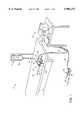
- FIG. 1is a perspective view of a representative electrosurgical system including an electrosurgical resectoscope, an electrically conducting liquid supply and an electrosurgical power supply constructed in accordance with the principles of the present invention
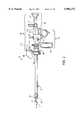
- FIG. 2is an enlarged perspective view of the resectoscope of FIG. 1 incorporating a return electrode oversheath and a resecting loop assembly according to the present invention
- FIG. 3illustrates an introducing sheath of the resectoscope of FIG. 2
- FIG. 4illustrates the return electrode oversheath of FIG. 2
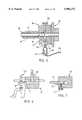
- FIG. 5illustrates a cross-sectional view of the proximal portion of the resectoscope of FIG. 2, illustrating the electrical connection with the return electrode oversheath;
- FIG. 6is a cross-sectional view of a proximal portion of the resectoscope in FIG. 2, illustrating the electrical connection with the resecting loop assembly;
- FIG. 7is a top section view of a proximal portion of the resectoscope
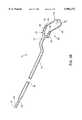
- FIG. 8Aillustrates the resecting loop assembly of FIG. 2
- FIG. 8Billustrates an alternative resecting loop assembly incorporating a return electrode
- FIG. 9is a section of a distal portion of the resecting loop assembly of FIG. 5, illustrating a resecting loop electrode
- FIG. 10Ais a front view of the resecting loop electrode
- FIGS. 10B-10Dillustrate alternative geometries for the resecting loop electrode
- FIG. 11is an enlarged view of the resecting loop electrode
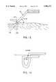
- FIG. 12is a schematic view illustrating the resecting loop electrode of FIG. 9 resecting a tissue portion at a target site;
- FIG. 13is an alternative embodiment of the resecting loop electrode of FIG. 9;
- FIG. 14is a transverse cross-sectional view of the resecting loop electrode of FIG. 9;
- FIGS. 15A and 15Bare transverse cross-sectional views of alternative loop electrodes according to the present invention.
- FIGS. 16A-16E, 17A, 17B, 18A, 18B, 19, 20A and 20Billustrate alternative electrode configurations according to the present invention
- FIG. 21illustrates a method of transurethral resection of prostate tissue with the electrosurgical system of FIG. 1;
- FIG. 22is an enlarged view illustrating the resection of a prostate tissue portion with the resecting loop electrode of the present invention.
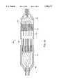
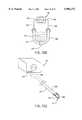
- FIG. 23illustrates a planar ablation probe for ablating tissue in confined spaces within a patient's body according to the present invention
- FIG. 24illustrates a distal portion of the planar ablation probe of FIG. 23
- FIG. 25Ais a front sectional view of the planar ablation probe, illustrating an array of semi-cylindrical active electrodes
- FIG. 25Bis a front sectional view of an alternative planar ablation probe, illustrating an array of active electrodes having opposite polarities;
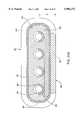
- FIG. 26is a top, partial section, view of the working end of the planar ablation probe of FIG. 23.
- FIG. 27is a side cross-sectional view of the working end of the planar ablation probe, illustrating the electrical connection with one of the active electrodes of FIG. 26;
- FIG. 28is a side cross-sectional view of the proximal end of the planar ablation probe, illustrating the electrical connection with a power source connector;
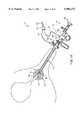
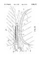
- FIG. 29is a schematic view illustrating the ablation of meniscus tissue located close to articular cartilage between the tibia and femur of a patient with the ablation probe of FIG. 23;
- FIG. 30is an enlarged view of the distal portion of the planar ablation probe, illustrating ablation or cutting of meniscus tissue
- FIG. 31illustrates a method of ablating tissue with a planar ablation probe incorporating a single active electrode
- FIG. 32is a schematic view illustrating the ablation of soft tissue from adjacent surfaces of the vertebrae with the planar ablation probe of the present invention
- FIGS. 33A-33Eillustrate another embodiment of the resecting loop electrode incorporating two active electrodes
- FIGS. 34A and 34Billustrate a resecting loop electrode incorporating two active electrodes connected to a common lead
- FIGS. 35A and 35Billustrate a resecting loop electrode with three active electrodes
- FIG. 36is a partial side cross-section of an alternative embodiment of the return electrode oversheath of FIG. 4.
- the present inventionprovides a system and method for selectively applying electrical energy to a target location within or on a patient's body, such as solid tissue or the like, particularly including procedures within confined spaces such as the spaces around the articular cartilage between the femur and tibia and spaces between adjacent vertebrae in the patient's spine, and procedures that involve resection of relatively larger pieces of tissue.
- a target locationwithin or on a patient's body, such as solid tissue or the like
- procedures within confined spacessuch as the spaces around the articular cartilage between the femur and tibia and spaces between adjacent vertebrae in the patient's spine, and procedures that involve resection of relatively larger pieces of tissue.
- the remaining disclosurewill be directed specifically to the resection of prostate tissue, and the cutting, shaping or ablation of meniscal tissue located adjacent articular cartilage and soft tissue covering vertebrae.
- the system and methodcan be applied equally well to procedures involving other tissues of the body, as well as to other procedures including open surgery, laparoscopic surgery, thoracoscopic surgery, and other endoscopic surgical procedures.
- proceduresinclude oral procedures, including gingival tissues and mucosal tissues located in the mouth or epidermal tissue on the outer skin, dermatological procedures, such as the treatment of tumors, abnormal tissues, and the like or, canalizing or boring channels or holes through tissue, such as the ventricular wall during transmyocardial revascularization procedures.
- laminectomy/disketomy proceduresfor treating herniated disks, decompressive laminectomy for stenosis in the lumbosacral and cervical spine, posterior lumbosacral and cervical spine fusions, treatment of scoliosis associated with vertebral disease, foraminotomies to remove the roof of the intervertebral foramina to relieve nerve root compression and anterior cervical and lumbar diskectomies.
- the present inventionis also useful for resecting tissue within accessible sites of the body that are suitable for electrode loop resection, such as the resection of prostate tissue, leiomyomas (fibroids) located within the uterus and other diseased tissue within the body.
- the present inventionis particularly useful in procedures where the tissue site is flooded or submerged with an electrically conducting fluid, such as isotonic saline.
- an electrically conducting fluidsuch as isotonic saline.
- the electrosurgical probewill comprise a shaft having a proximal end and a distal end which supports one or more active electrode(s).
- the shaftmay assume a wide variety of configurations, with the primary purpose being to mechanically support the active electrode(s) and permit the treating physician to manipulate the electrode(s) from a proximal end of the shaft.
- the shaftwill be a narrow-diameter rod or tube, more usually having dimensions which permit it to be introduced into a body cavity, such as the arthroscopic cavity, through an associated trocar or cannula in a minimally invasive procedure, such as arthroscopic, laparoscopic, thoracoscopic, and other endoscopic procedures.
- the shaftwill typically have a length of at least 5 cm for oral procedures and at least 10 cm, more typically being 20 cm, or longer for endoscopic procedures.
- the shaftwill typically have a diameter of at least 1 mm and frequently in the range from 1 to 10 mm.
- the shaftmay have any suitable length and diameter that would facilitate handling by the surgeon.
- the shaftmay be rigid or flexible, with flexible shafts optionally being combined with a generally rigid external tube for mechanical support.
- Flexible shaftsmay be combined with pull wires, shape memory actuators, and other known mechanisms for effecting selective deflection of the distal end of the shaft to facilitate positioning of the electrode(s)
- the shaftwill usually include a plurality of wires or other conductive elements running axially therethrough to permit connection of the electrode(s) to a connector at the proximal end of the shaft. Specific shaft designs will be described in detail in connection with the figures hereinafter.
- the present inventionmay use a single active electrode or an electrode array distributed over a distal contact surface of a probe.
- the arrayusually includes (but is not limited to) a plurality of independently current-limited and/or powercontrolled electrodes to apply electrical energy selectively to the target tissue while limiting the unwanted application of electrical energy to the surrounding tissue and environment resulting from power dissipation into surrounding electrically conductive liquids, such as blood, normal saline, and the like.
- the electrodesmay be independently current-limited by isolating the electrodes from each other and connecting each electrodes to a separate power source that is isolated from the other electrode terminals.
- the electrodesmay be connected to each other at either the proximal or distal ends of the probe to form a single wire that couples to a power source.
- each individual electrode in the electrode arrayis electrically insulated from all other electrodes in the array within said probe and is connected to a power source which is isolated from each of the other electrodes in the array or to circuitry which limits or interrupts current flow to the electrode when low resistivity material (e.g., blood or electrically conductive saline irrigant) causes a lower impedance path between the common electrode and the individual electrode terminal.
- low resistivity materiale.g., blood or electrically conductive saline irrigant
- the isolated power sources for each individual electrodemay be separate power supply circuits having internal impedance characteristics which limit power to the associated electrode terminal when a low impedance return path is encountered, may be a single power source which is connected to each of the electrodes through independently actuatable switches or may be provided by independent current limiting elements, such as inductors, capacitors, resistors and/or combinations thereof.
- the current limiting elementsmay be provided in the probe, connectors, cable, controller or along the conductive path from the controller to the distal tip.
- the resistance and/or capacitancemay occur on the surface of the active electrode(s) due to oxide layers which form selected electrode terminals (e.g., titanium or a resistive coating on the surface of metal).
- the inventionis not limited to electrically isolated electrode terminals, or even to a plurality of electrode terminals.
- the array of active electrode terminalsmay be connected to a single lead that extends through the probe shaft to a power source of high frequency current.
- the probemay incorporate a single. electrode that extends directly through the probe shaft or is connected to a single lead that extends to the power source.
- the inventionmay also use current limiting means to apply electrical energy selectively to the target tissue while limiting the unwanted application of electrical energy to the surrounding tissue.
- the electrodemay be connected to current limiting elements or to circuitry which limits or interrupts current flow to the electrode when low resistivity material (e.g., blood or electrically conductive saline irrigant) causes a lower impedance path between the common electrode and the electrode.
- low resistivity materiale.g., blood or electrically conductive saline irrigant
- the current limiting elements or circuitrymay be configured to completely interrupt or modulate current flow to the electrode, for example, when a certain percentage of the electrode surface is in contact with low resistivity material.
- the current flowwill be modulated or completely interrupted when, for example, a large portion of the electrode surface is exposed to fluids and, therefore, not in contact with the target tissue. In this manner, current can be selectively applied to the target tissue, while minimizing current flow to surrounding fluids and adjacent non-target tissue structures.
- the active electrode(s)will have an active portion or surface with surface geometries shaped to promote the electric field intensity and associated current density along the leading edges of the electrodes. Suitable surface geometries may be obtained by creating electrode shapes that include preferential sharp edges, or by creating asperities or other surface roughness on the active surface(s) of the electrodes. Electrode shapes according to the present invention can include the use of formed wire (e.g., by drawing round wire through a shaping die) to form electrodes with a variety of cross-sectional shapes, such as square, rectangular, L or V shaped, or the like. Electrode edges may also be created by removing a portion of the elongate metal electrode to reshape the cross-section.
- materialcan be ground along the length of a round or hollow wire electrode to form D or C shaped wires, respectively, with edges facing in the cutting direction.
- materialcan be removed at closely spaced intervals along the electrode length to form transverse grooves, slots, threads or the like along the electrodes.
- the active electrode surface(s)may be modified through chemical, electrochemical or abrasive methods to create a multiplicity of surface asperities on the electrode surface. These surface asperities will promote high electric field intensities between the active electrode surface(s) and the target tissue to facilitate ablation or cutting of the tissue.
- surface asperitiesmay be created by etching the active electrodes with etchants having a PH less than 7.0 or by using a high velocity stream of abrasive particles (e.g., grit blasting) to create asperities on the surface of an elongated electrode.
- the active electrode surface(s)may be provided by assembling alternating layers of electrically conductive members (i.e., electrodes) and electrically insulating spacers.
- an active electrode having multiple circular edgesmay be constructed using alternating layers of concentric, thin metal washers (e.g., titanium, stainless steel or the like), having outside diameters D.
- the washersmay be separated by thin concentric insulating spacers (e.g., anodized aluminum, ceramic, glass, glass ceramic, plastic, etc.) having an outside diameter D' which is less than D so that the edges of the metal washers extend beyond the insulating spacers.
- the electrode assemblycan be constructed by placing the metal washers over a central, electrically conductive mandrel, which provides for electrical communication between the power source and the multiple metal "washer" shaped electrodes.
- the electrodesare preferably at the same source polarity since they are in contact with a common electrical lead (i.e., mandrel).
- the electrode assemblymay include a split mandrel having opposite polarities such that adjacent metal washers are at opposite polarities to effect one or more pairs of bipolar washer shaped electrodes.
- the metal electrodesmay have any shape suitable for the intended ablation or resection of tissue, e.g., square, circular, hexagonal octagonal, triangular, etc.
- the perimeter of the thin metal electrodemay be stamped, machined, notched or otherwise modified to increase the electric field intensity at the working (outer) surface of the metal electrode.
- the metal electrodesmay be coated with an electrically insulating layer (e.g., ceramic, glass or porcelain) of sufficient thickness to provide spacing between adjacent electrode members, whether the electrode assembly is monopolar or bipolar.
- the insulating coatingmay extend up to the perimeter of the metal electrode (e.g., washer), or it may be recessed from the perimeter to expose a greater portion of the edges of the electrodes.
- the active electrodeswill also have a "non-active" portion or surface(s) to selectively reduce undesirable current flow from the non-active portion or surface(s) into tissue or surrounding electrically conducting liquids (e.g., isotonic saline, blood or blood/non-conducting irrigant mixtures).
- the "non-active" electrode surface(s)will be coated with an electrically insulating material.
- evaporative or sputtering techniquese.g., SiO 2 or Si 3 N 4
- the method of the present inventioncomprises positioning an electrosurgical probe adjacent the target tissue so that at least one active electrode is brought into close proximity to the target site.
- a return electrodeis positioned within an electrically conducting liquid, such as isotonic saline, to generate a current flow path between the target site and the return electrode.
- High frequency voltageis then applied between the active and return electrode through the current flow path created by the electrically conducting liquid in either a bipolar or monopolar manner.
- the probemay then be translated, reciprocated or otherwise manipulated to cut the tissue or effect the desired depth of ablation.
- the current flow pathmay be generated by submerging the tissue site in an electrical conducting fluid (e.g., arthroscopic surgery and the like) or by directing an electrically conducting liquid along a fluid path past the return electrode and to the target site to generate the current flow path between the target site and the return electrode.
- an electrical conducting fluide.g., arthroscopic surgery and the like
- This latter methodis particularly effective in a dry environment (i.e., the tissue is not submerged in fluid), such as open, endoscopic or oral surgery, because the electrically conducting liquid provides a suitable current flow path from the target site to the return electrode.
- the active electrode(s)are preferably disposed at the distal end of the probe and the return electrode is spaced from the active electrode and enclosed within an insulating sheath. This minimizes exposure of the return electrode to surrounding tissue and minimizes possible shorting of the current between the active and return electrodes.
- the probewill typically be passed through a conventional trocar cannula while viewing of the operative site is provided through the use of an endoscope disposed in a separate cannula.
- a high frequency voltageis applied between the active portion of the active electrode(s) and the return electrode to develop high electric field intensities in the vicinity of the target tissue site.
- the high electric field intensitieslead to electric field induced molecular breakdown of target tissue through molecular dissociation (rather than thermal evaporation or carbonization).
- Applicantbelieves that the tissue structure is volumetrically removed through molecular disintegration of larger organic molecules into smaller molecules and/or atoms, such as hydrogen, oxides of carbon, hydrocarbons and nitrogen compounds. This molecular disintegration completely removes the tissue structure, as opposed to dehydrating the tissue material by the removal of liquid within the cells of the tissue, as is typically the case with electrosurgical desiccation.
- the high electric field intensitiesmay be generated by applying a high frequency voltage that is sufficient to vaporize the electrically conducting liquid over at least a portion of the active electrode(s) in the region between the distal tip of the active electrode and the target tissue. Since the vapor layer or vaporized region has a relatively high electrical impedance, it increases the voltage differential between the active electrode tip and the tissue and causes ionization within the vapor layer due to the presence of an ionizable species (e.g., sodium when isotonic saline is the electrically conducting fluid). This ionization, under optimal conditions, induces the discharge of energetic electrons and photons from the vapor layer and to the surface of the target tissue.
- an ionizable speciese.g., sodium when isotonic saline is the electrically conducting fluid
- This energymay be in the form of energetic photons (e.g., ultraviolet radiation), energetic particles (e.g., electrons) or a combination thereof.
- energetic photonse.g., ultraviolet radiation
- energetic particlese.g., electrons
- Ser. No. 08/561,958the complete disclosure of which has already been incorporated herein by reference.
- the voltage applied between the return electrode and the active electrode(s)will be at high or radio frequency, typically between about 5 kHz and 20 MHz, usually being between about 30 kHz and 2.5 MHz, and preferably being between about 50 kHz and 400 kHz.
- the RMS (root mean square) voltage appliedwill usually be in the range from about 5 volts to 1000 volts, preferably being in the range from about 50 volts to 800 volts, and more preferably being in the range from about 100 volts to 400 volts.
- the peak-to-peak voltagewill be in the range of 200 to 2000 volts and preferably in the range of 300 to 1600 volts and more preferably in the range of 500 to 1200 volts.
- the preferred power source of the present inventiondelivers a high frequency voltage selectable to generate average power levels ranging from tens of milliwatts to tens of watts up to hundreds of watts per electrode, depending on the number of electrodes, the target tissue being ablated, the rate of ablation desired or the maximum allowed temperature selected for the probe tip.
- the power sourceallows the user to select the voltage level according to the specific requirements of a particular oral surgery, dermatological procedure, open surgery or other endoscopic surgery procedure.
- the power sourcemay be current limited or otherwise controlled so that undesired heating of electrically conductive fluids or other low electrical resistance media does not occur.
- current limiting inductorsare placed in series with each independent electrode terminal, where the inductance of the inductor is in the range of 10 uH to 50,000 uH, depending on the geometry and size of the electrode(s), the electrical properties of the target tissue, the desired ablation rate and the operating frequency.
- capacitor-inductor (LC) circuit structuresmay be employed, as described previously in co-pending PCT application No. PCT/US94/05168, the complete disclosure of which is incorporated herein by reference. Additionally, current limiting resistors may be selected.
- these resistorswill have a large positive temperature coefficient of resistance so that, as the current level begins to rise for any individual electrode in contact with a low resistance medium (e.g., saline irrigant), the resistance of the current limiting resistor increases significantly, thereby minimizing the power delivery from said electrode into the low resistance medium (e.g., saline irrigant).
- a low resistance mediume.g., saline irrigant
- regulated current flow to each electrode terminalmay be provided by a multi-channel power supply.
- Such a multi-channel power supplythus provides a substantially constant current source with selectable current level in series with each electrode terminal, wherein all electrodes will operate at or below the same, user selectable maximum current level. Current flow to all electrode terminals could be periodically sensed and stopped if the temperature measured at the surface of the electrode array exceeds user selected limits. Particular control system designs for implementing this strategy are well within the skill of the art.
- a power supplyfor energizing one or more electrodes having use of one or more channels of user-selectable voltage levels.
- the channelswould incorporate an active control mechanism for limiting current levels below a preselected maximum level.
- the preselected maximum current leveldepends on the size and configuration of the electrode(s), and may be "factory" set or user selectable.
- an indicator devicemay be included in the probe (e.g., a resistor having a resistance value which corresponds to the maximum current level appropriate to a specific electrode configuration) such that the power supply can (1) first measure the indicator device value (e.g., measure the resistance of the indicator) contained within the probe; and (2) then set the maximum current level which corresponds to that resistance value.
- a range of probe designshaving greatly differing electrode size(s) and configuration(s) can be energized since the power supply will automatically adjust the maximum current level to correspond to each particular electrode size and configuration.
- Yet another alternativeinvolves the use of one or several power supplies which allow one or several electrodes to be simultaneously energized and which include active control means for limiting current levels below a preselected maximum level.
- active control meansfor limiting current levels below a preselected maximum level.
- only one or several electrodeswould be simultaneously energized for a brief period.
- Switching meanswould allow the next one or several electrodes to be energized for a brief period.
- a resistance measurement meansmay be employed for each electrode prior to the application of power wherein a (measured) low resistance (below some preselected level) will prevent that electrode from being energized during a given cycle.
- the sequential powering and control scheme of the present inventionwould function in a manner similar to an automobile distributor.
- an electrical contactrotates past terminals connected to each spark plug.
- each spark plugcorresponds to the exposed surface of each of the electrodes.
- the present inventionincludes the means to measure the resistance of the medium in contact with each electrode and cause voltage to be applied only if the resistance exceeds a preselected level.
- the distal end of the probe or the active electrode(s)will usually be maintained at a small distance away from the target tissue surface. This small spacing allows for the continual resupply of electrically conducting liquid into the interface between the active electrode(s) and the target tissue surface. This continual resupply of the electrically conducting liquid helps to ensure that the thin vapor layer will remain between active electrode(s) and the tissue surface.
- dynamic movement of the active electrode(s) over the tissue siteallows the electrically conducting liquid to cool the tissue surrounding recently ablated areas to minimize thermal damage to this surrounding tissue.
- the active electrode(s)will be about 0.02 to 2 mm from the target tissue and preferably about 0.05 to 0.5 mm during the ablation process.
- One method of maintaining this spaceis to translate and/or rotate the probe transversely relative to the tissue, i.e., a light brushing motion, to maintain a thin vaporized layer or region between the active electrode and the tissue.
- a light brushing motioni.e., a light brushing motion
- the active electrode or the electrode arraywill have an exposed length in the range from about 2.5 to 12.5 mm.
- current-limiting inductorshaving values of about 0 to 100 uH, preferably about 25 to 50 uH, are suitable for establishing the requisite conditions for selective ablation described above (i.e., the generation of sufficient electric field intensities to form a vapor layer in the electrically conducting liquid and to induce the discharge of energy through the vapor layer to ablate tissue while minimizing substantial necrosis beyond several cell layers).
- the active electrode(s)may have a substantially smaller exposed length away from the probe than described above (on the order of about 0 to 0.5 mm). This configuration is described in Ser. No. 08/561,958 (attorney docket 16238-000700), the complete disclosure of which has already been incorporated herein by reference.
- electrosurgical system 11constructed according to the principles of the present invention.
- electrosurgical system 11generally comprises an electrosurgical resectoscope 10 incorporating a resecting loop assembly 12 with an active electrode (not shown in FIG. 1), and a return electrode oversheath 16 circumscribing a portion of the resecting loop assembly 12.
- the resectoscope 10is connected to a power supply 28 for providing high frequency voltage to the active electrode and a liquid source 21 for supplying electrically conducting fluid 50 to a target tissue (see FIGS. 21 and 22).
- a liquid supply tube 15removably couples liquid source 21, (e.g., a bag of fluid elevated above the surgical site or having a pumping device), with return electrode oversheath 16.
- liquid source 21e.g., a bag of fluid elevated above the surgical site or having a pumping device
- return electrode oversheath 16e.g., a bag of fluid elevated above the surgical site or having a pumping device
- a manual control valve 17may also be provided between the proximal end of return electrode 16 and supply tube 15 to allow the surgical team to regulate the flow of electrically conducting liquid 50.
- Power supply 28has a selector 30 for varying the applied voltage level.
- Power supply 28also includes a mechanism for energizing the active electrode of resectoscope 10 through the depression of a pedal 39 in a foot pedal 37 positioned close to the user.
- the foot pedal 37will usually include a second pedal 38 for remotely adjusting the energy level applied to electrode 14.
- first pedal 37will apply a higher voltage level suitable for cutting and ablating tissue and second pedal 38 will apply a lower voltage level suitable for coagulating and sealing tissue, such as a transected blood vessel (discussed in further detail below).
- PCT US 94/051168A specific design of one power supply which may be used with the electrosurgical probe of the present invention is described in parent application PCT US 94/051168, the full disclosure of which has previously been incorporated herein by reference.
- resectoscope 10is preferably a conventional or specialized resectoscope that is adapted for use with resecting loop assembly 12 and return electrode oversheath 16 according to the present invention.
- Existing resectoscopes useful with the present inventioncan be found under the trade names of USA Elite System Resectoscope from Circon/ACMI of Stamford, Connecticut and OES Resectoscope from Olympus Corporation of Lake Success, N.Y. Loop assembly 12 and oversheath 16 may also be used without a resectoscope. In this configuration, the surgeon may use other means for viewing the surgical site, such as other endoscopes.
- Resectoscope 10generally includes a proximal handle 64, and an introducing sheath 60 (FIG. 3) having a hollow, tubular shaft 62 for axially receiving loop assembly 12.
- Sheath 60also includes a proximal hub 98 for connecting sheath 60 to handle 64 and return electrode oversheath 16 (discussed in detail below).
- handle 64includes a viewing assembly 66, an irrigant/suction assembly 68 and an actuation assembly 70 for axially reciprocating loop assembly 12 relative to shaft 62.
- actuation assembly 70includes a coupling housing 72 having an outer knob or thumbscrew 74 that can be tightened to secure a proximal connector leg 76 of loop assembly 12 to an electrically conducting inner sleeve member 78 of coupling housing 72 (FIG. 7).
- Sleeve member 78electrically couples leg 76 to a resecting loop terminal 80 (FIG. 6), which can be removably coupled to power supply 28 to provide power to loop assembly 12 (discussed in further detail below).
- Coupling housing 72is axially translatable relative to introducing sheath 60 so that resecting loop assembly 12 can be axially translated relative to the distal end 94 of tubular shaft 62 (see FIG. 3).
- resectoscope 10will usually include a finger loop 82 and a thumb loop 84 suitably connected to housing 72 for reciprocating housing 72 and loop assembly 12 relative to the distal end 94 of shaft 62.
- finger loop 82 and thumb loop 84suitably connected to housing 72 for reciprocating housing 72 and loop assembly 12 relative to the distal end 94 of shaft 62.
- other control means for axially reciprocating loop assembly 12can be utilized with the present invention, such as rotatable knobs, trigger buttons, and the like.
- electrosurgical system 11will preferably include a return electrode oversheath 16 for completing the current path between active electrode 14 and power supply 28 (discussed in detail below). It should be made clear, however, that the present invention is not limited to a bipolar modality and, may utilize a monopolar mode. In this configuration, return electrode oversheath 16 is not required. Instead, voltage is applied between an active electrode 14 and a dispersive electrode plate externally attached to the patient's skin such that electric current flows from active electrode 14, through the patient's body, to the dispersive electrode.
- Return electrode oversheath 16generally includes an electrically conducting, hollow shaft 86 coupled to a proximal housing 88 with a suitable epoxy adhesive, for example.
- the inner and outer surfaces of shaft 86are covered with an electrically insulating layer 90 over the entire length of shaft 86 except for a distal end portion 92, which remains exposed to generate a current path from active loop assembly 12 (discussed below).
- Electrically insulating layer 90may comprise a heat shrinkable tubing material, such as KynarTM, or it may be a deposited coating, such as ParyleneTM, polytetrafluoroethylene, polyimide, or the like.
- the electrically insulating layer 90 over return electrode shaft 86prevents direct electrical contact between the return electrode and any adjacent body structure or the surgeon. Such direct electrical contact between a body structure (e.g., tendon) and an exposed return electrode member could result in unwanted heating and necrosis of the structure at the point of contact causing necrosis. If return electrode oversheath 16 is being used with an electrically insulating resectoscope sheath (e.g., a plastic tubular sheath), the inner surface of shaft 86 may remain exposed (i.e., no electrically insulating layer 90).
- an electrically insulating resectoscope sheathe.g., a plastic tubular sheath
- Return electrode shaft 86will have an inner diameter large enough to slide shaft 86 over tubular shaft 62 of introducing sheath 60 (FIG. 5). Distal end portion 94 of shaft 62 is introduced through an opening 96 in proximal housing 88 and axially delivered through return electrode shaft 86 until housing 88 abuts against proximal hub 98 of introducing sheath 60.
- Return electrode oversheath 16further includes a fastener, such as a thumbscrew 100, to secure the return electrode to introducing sheath 60.
- return electrode shaft 86has an opening 102 aligned with thumbscrew 100 so that the thumbscrew 100 can engage tubular shaft 62 of introducing sheath 60.
- Thumbscrew 100preferably comprises an electrically insulating material, such as UltemTM, to minimize electrical shock to the surgeon during use of resectoscope 10.
- resectoscope 10is electrically connected to power supply 28 with cable 34, which is removably connected to power supply 28 by a power supply connector plug 26.
- Cable 34includes an adaptor 130 that branches into a first lead 132 which is removably connected via plug 134 to a return electrode terminal 136, e.g., a minibananna plug, and a second lead 138 which is removably connected via plug 140 to resecting loop terminal 80 (FIG. 21).
- return electrode plug 134includes a recessed electrical receptacle 142 which permits plug 134 to be inserted into a cavity 144 of return electrode housing 88. This provides a fluid-tight seal between housing 88 and plug 134 to minimize the possibility of electrical shock to the surgeon or patient if the controller is energized prior to the complete connection of plug 134 and electrode terminal 136.
- handle 64 of resectoscope 10will also usually include a viewing assembly 66 and an irrigant/suction assembly 68.
- viewing assembly 66includes a hub 150, a telescopic lumen 152 extending through shaft 62 of introducing sheath 60 and an eyepiece 154 coupled to lumen 152 to permit viewing of the target site by the physician.
- a cameramay be attached to the proximal end of hub 150 to allow display of the surgical site on a video monitor.
- a fiberoptic light source(not shown) is typically attached to hub 150 to illuminate the target site.
- Irrigant/suction assembly 68includes proximal hub 98 of introducing sheath 60, and a connector 160 extending from hub 98 and coupled to supply line 15 for introducing a sterile irrigant, typically isotonic saline, to the surgical site.
- Connector 160is fluidly coupled to an axial lumen 162 within shaft 62 (see FIG. 3). Fluid may also be withdrawn through axial lumen 162 or a second lumen (also not shown) within shaft 62 to withdraw contaminated fluids from the surgical site and to facilitate the surgeon's view.
- Loop assembly 12generally includes an electrically insulating hollow shaft 180 with proximal connection leg 76 and a distal active electrode assembly 182.
- Active electrode assembly 182includes a bifurcated support member 184 having a pair of hollow arms 186, 188 extending from a distal end 190 of shaft 180.
- a hollow, electrically insulating tubular member 192extends from each arm 186, 188 of bifurcated support member 184, and a tubular resecting loop electrode 194 extends from each tubular member 192.
- Tubular members 192will comprise a suitable insulating material (e.g., ceramic or glass material, such as alumina, zirconia and the like).
- a suitable insulating materiale.g., ceramic or glass material, such as alumina, zirconia and the like.
- the preferred support matrix materialis alumina, available from Kyocera Industrial Ceramics Corporation, Elkgrove, Illinois, because of its good electrically insulating properties, high flexural modulus, resistance to carbon tracking, biocompatibility, and high melting point.
- resecting loop assembly 12may incorporate the return electrode so that only a single instrument is required for bipolar resection of tissue (i.e., a return electrode oversheath is not required).
- a resecting loop assembly 12'according to the present invention includes an electrically conducting shaft 180' covered with an outer electrically insulating layer 181.
- Shaft 180'includes a distal exposed portion 183 for completing the current return path with active electrode assembly 182, and a proximal exposed portion 185 for connecting return electrode 180 to power supply 28.
- An electrically insulating layer 192insulates shaft 180 from active electrode 196 and exposed portion 185 from proximal connection leg 76.
- loop electrode 194comprises an elongate loop body 196 having first and second ends 198, 199 coupled to and extending within tubular members 192.
- Resecting loop electrode 194is preferably composed of a corrosion resistant, electrically conductive metal or alloy, such as platinum, titanium, tantalum, tungsten, stainless steel, nickel and cobalt-based alloys and the like. It should be understood that loop electrode 194 may have configurations other than that described above and shown in FIGS. 8-11.
- the electrodefits within the available space within the working end of a resectoscope, which generally includes fiber optic or "glass rod” optical viewing and lighting means, articulating resecting means and irrigant supply ports; (2) the electrode is shaped and sized to allow the surgeon to view the tissue site; and (3) the electrode is configured to cut chips or small portions of tissue from the target site.
- the "loop" electrodemay have a variety of shapes, such as semi-circular, square, triangular, rectangular, or multi-sided geometry (see FIGS. 10B-10D, for example).
- the semi-circular loop electrode of FIG. 10Ais preferred because it easily fits within the cylindrical bore of conventional resectoscopes. In addition, this shape tends to facilitate good visibility for the surgeon, and it produces rapid resection of tissue.
- Loop electrode 194may also comprise a plurality of active electrodes that are either coupled together or electrically isolated from each other (discussed below). In the latter case, electrosurgical system 11 may include current limiting elements or circuitry to independently limit current to the electrodes based on the impedance between each electrode and return electrode 92, as described above.
- electrical connections 200such as lead wires, metal tubes or the like, extend through one or both arms 186, 188 of support member 184 and shaft 180 to electrically couple one or both ends 198, 199 of resecting loop electrode 196 with connector leg 76.
- Electrical connections 200are coupled to loop electrode 194 and connector leg 74 using crimping, soldering, welding or other suitable methods.
- Electrical connections 200are preferably covered with an insulating sheath (not shown) except for exposed distal and proximal portions of connections 200 that are coupled to loop electrode 194 and leg 74, respectively.
- resecting loop electrode 194preferably has a semi-cylindrical transverse cross-section along its entire length to form first and second ends 204, 206 that define a slot 208 therebetween.
- Ends 204, 206each define relatively sharp edges 210 that promote high electric field intensities around ends 204, 206 to enhance the tissue cutting capabilities of resecting loop assembly 12.
- Ends 204, 206 and edges 210 of loop electrode 194form an active portion of electrode that promotes sufficiently high electric field intensities sufficient to reach the threshold conditions for formation of a vapor layer in the electrically conductive liquid, as discussed above.
- resecting loop electrode 194is preferably oriented so that ends 204, 206 are generally parallel to the cutting direction (i.e., facing the target tissue, see FIG. 14). This orientation facilitates the formation of a vapor layer between ends 204, 206 and the target tissue and directs the energy induced from the vapor layer to the target tissue.
- loop electrode 194further includes a non-active portion 212 on the opposite side from ends 204, 206.
- Non-active portion 212preferably defines a relatively smooth surface to reduce the electric field intensities around portion 212, thereby minimizing undesirable current flow into fluids and surrounding tissue.
- non-active portion 212may include an insulating layer (not shown) to further minimize undesirable tissue damage. This configuration allows the surgeon to more selectively ablate tissue at the target site.
- loop electrode 194is formed from a hollow tube that is filed or ground down to form the semi-circular or "C" shaped cross section.
- the filing operationcreates four relatively sharp corners 210 along the length of the bipolar loop electrode 194, as shown in FIG. 11.
- the thin metal wall tubingis filed or ground up to, but not exceeding the diametral line of the tubing.
- loop electrode 194will have an outside diameter of about 0.005 to 0.03 inch and a wall thickness of about 0.001 to 0.01 inch.
- FIGS. 15A and 15Billustrate alternative embodiments of bipolar loop electrode 194.
- loop electrode 194may have a "D" shaped cross section having a substantially planar active surface 300.
- electrode 194is preferably fabricated from a solid wire that is ground or filed down similarly to the "C" shaped electrode configuration discussed above to form electrode edges 210.
- electrode 194may also have a double slotted configuration that is generally formed by grinding both sides of a hollow tube.
- loop electrode 194may be constructed from a formed wire (e.g., a round wire that has been drawn through a shaping die) shaped to create corners on the periphery of the extended loop electrode surface.
- FIGS. 16A-16Eillustrate examples of electrode cross-sectional shapes that may be used with the present invention.
- FIGS. 17A, 17B, 18A, 18B and 19illustrate other alternatively shaped electrodes having transverse grooves or slots formed therein to promote high electric field intensities.
- loop electrode 302comprises an elongate body 304 having a plurality of spaced, transverse slots 306 (FIG. 17A) or grooves 308 (FIG. 17D) formed therein.
- the electrode edges 210 of slots 306 and grooves 308will generally form the "active" portion of the electrode, while an opposing, substantially planar surface 310 forms the "non-active" portion of the electrode 302.
- An insulating layermay be formed over surface 310 to prevent undesirable current flowing from this surface 310 to adjacent tissue.
- electrode 302'may include grooves 312 on both sides so that both sides of electrode 302' are "active", as shown in FIG. 18A by virtue of the electrode edges 210 formed by the grooves or slots 312.
- electrode 314may have a "necklace" shape, in which electrode members are pre-shaped, perforated and then placed on an elongate support member (similar to beads on a necklace).
- electrode 314includes an elongate support member 316, which may comprise an electrically conducting or insulating material, and a plurality of electrode disks 318 having an inner hole for receiving support member 316. Electrode disks 318 may be in contact with each other or longitudinally spaced from each other. In the latter configuration, support member 316 will be electrically conducting to electrically connect the disks 318 with each other.
- each electrode disk 318may be separated from each other by an insulating spacer 320. In this embodiment, the electrodes 318 may be electrically isolated from each other so that current limiting elements can be utilized to minimize undesirable current flow into surrounding fluids, as described above.
- FIGS. 20A and 20Billustrate further alternative embodiments of the loop electrode according to the present invention.
- a formed wirehas been shaped (e.g., by a shaping die) to form a "V" shape electrode 330. Since the ends 331, 332 of the "V" will promote high electric field intensities, they will preferably face in the cutting direction.
- an insulating layer 334is formed onto the backside 335 of the "V”.
- FIG. 20Billustrates a "C" shaped electrode 336 having ends 337, 338 facing the cutting direction and an insulating layer 340 cover an opposite side 342 of electrode 336.
- resecting loop electrode 194is aligned with a plane forming an obtuse angle with the longitudinal axis of shaft 180.
- the obtuse angleis usually about 110 to 170 degrees, preferably about 120 to 150 degrees.
- this orientationsignificantly facilitates initiating the requisite conditions for forming the vapor layer and inducing the discharge of energy therefrom.
- a greater fraction of loop electrode 194is in direct contact with the tissue so that a greater fraction of the applied energy is directed to the tissue to be resected and a greater length of the resection loop is employed to cut the same depth of tissue.
- the duration of electrode contact with tissueis at least 30%, and usually at least 40%, greater at the 120° to 150° orientation than at the 90° orientation (see FIG. 15). This results in improved hemostasis of the resected tissue because there is more time to seal transected blood vessels with each pass of the resecting loop. In addition, a smaller fraction of loop electrode 194 is exposed to electrically conducting fluid surrounding the tissue, which minimizes undesirable current flow through this fluid.
- FIGS. 21 and 22a method for applying electrical energy to a target tissue in the patient's body will now be described.
- an exemplary procedure for treating an enlarged prostate 222 with electrosurgical system 11will be described.
- Introducing sheath 60, return electrode oversheath 16, resecting loop assembly 112are introduced transurethrally to the urethra 226 within prostate 222.
- return electrode oversheath 16will not be introduced, and a dispersive electrode (not shown) will be externally attached to the patient's skin.
- voltagecan be applied from power supply 28 (see FIG. 1) between resecting loop electrode 194 and the exposed portion 92 of return electrode 16.
- the applied voltage levelswill be above about 500 volts (peak-to-peak).
- the cutting and resection of prostatic tissue 222is achieved by engaging resecting loop electrode 194 against the prostatic tissue or positioning loop electrode 194 in close proximity to the prostatic tissue while simultaneously applying voltage from power supply 28 and axially displacing loop electrode 194 towards the distal end of introducing sheath 60 as illustrated by resection vector 299 in FIG. 22.
- electrically conducting irrigante.g., isotonic saline
- liquid supply 21e.g., isotonic saline
- the electrically conducting liquidprovides a pathway for electrical current flow between prostatic tissue 222 and return electrode 92, as illustrated by the current flux lines 360 in FIG. 22.
- the design of the surface geometry of resecting loop electrode 194promotes high current densities at the surface of electrode 194, especially at the shaped edges. In contrast, the current density decreases rapidly with distance from the surface of resecting loop 194. Since the extent of the exposed portion 92 of return electrode will be about 2 to 4 cm, the surface area of exposed portion 92 will be about 5 to 10 cm 2 . In contrast, the surface area of the resecting loop electrode 194 is about 0.003 cm 2 . As a result, the current density at the return electrode 92 is 1,700 to 3,400 times smaller than at the resecting loop 194 resulting in current density levels below the threshold of injury to living tissue.
- resecting loop electrode 194may be used specifically for coagulating and sealing of a transected blood vessel by engaging the tissue at the locus of the bleeding vessel and lightly applying pressure while simultaneously applying a lower voltage level, i.e., a voltage level which is below the threshold of effecting cutting or resection of tissue.
- an applied voltage level of less than 500 volts (peak-to-peak), preferably less than 400 volts (peak-to-peak)will be sufficient to effect coagulation of transected blood vessels without cutting or resection of tissue.
- This dual mode of operation of resecting loop 112is preferably accomplished by providing dual footpedal 37, which includes a cutting mode pedal 39 and a coagulation mode pedal 38. Alternatively, the dual mode may be carried out with voltage control buttons 30.
- telescopic lumen 152(FIG. 21) and the attached return electrode oversheath 16 can be withdrawn from introducing sheath 160 of resectoscope 10 by releasing a mechanical locking member 350.
- the open lumen of introducing sheath 60can be used to remove the "chip-shaped" tissue portions 352 (FIG. 22) formed during the resection process.
- FIG. 23illustrates an exemplary planar ablation probe 400 according to the present invention. Similar to the resectoscope described above, probe 400 can be incorporated into electrosurgical system 11 (or other suitable systems) for operation in either the bipolar or monopolar modalities.
- Probe 400generally includes a support member 402, a distal working end 404 attached to the distal end of support member 402 and a proximal handle 408 attached to the proximal end of support member 402.
- handle 406includes a handpiece 408 and a power source connector 410 removably coupled to handpiece 408 for electrically connecting working end 404 with power supply 28 through cable 34 (see FIG. 1).
- planar ablation probe 400is configured to operate in the bipolar modality.
- support member 402functions as the return electrode and comprises an electrically conducting material, such as titanium, or alloys containing one or more of nickel, chromium, iron, cobalt, copper, aluminum, platinum, molybdenum, tungsten, tantalum or carbon.
- support member 402is an austenitic stainless steel alloy, such as stainless steel Type 304 from MicroGroup, Inc., Medway, Mass.
- support member 402is substantially covered by an insulating layer 412 to prevent electric current from damaging surrounding tissue.
- An exposed portion 414 of support member 402functions as the return electrode for probe 400. Exposed portion 414 is preferably spaced proximally from active electrodes 416 by a distance of about 1 to 20 mm.
- planar ablation probe 400further comprises a plurality of active electrodes 416 extending from an electrically insulating spacer 418 at the distal end of support member 402.
- probe 400may include a single electrode depending on the size of the target tissue to be treated and the accessibility of the treatment site (see FIG. 30, for example).
- Insulating spacer 418is preferably bonded to support member 402 with a suitable epoxy adhesive 419 to form a mechanical bond and a fluid-tight seal.
- Electrodes 416usually extend about 2.0 mm to 20 mm from spacer 418, and preferably less than 10 mm.
- a support tongue 420extends from the distal end of support member 402 to support active electrodes 416.
- Support tongue 420 and active electrodes 416have a substantially low profile to facilitate accessing narrow spaces within the patient's body, such as the spaces between adjacent vertebrae and between articular cartilage and the meniscus in the patient's knee. Accordingly, tongue 420 and electrodes 416 have a substantially planar profile, usually having a combined height He of less than 4.0 mm, preferably less than 2.0 mm and more preferably less than 1.0 mm (see FIG. 25). In the case of ablation of meniscus near articular cartilage, the height He of both the tongue 420 and electrodes 416 is preferably between about 0.5 to 1.5 mm.
- the width of electrodes 416 and support tongue 420will usually be less than 10.0 mm and preferably between about 2.0 to 4.0 mm.
- Support tongue 420includes a "non-active" surface 422 opposing active electrodes 416 covered with an electrically insulating layer (not shown) to minimize undesirable current flow into adjacent tissue or fluids.
- Non-active surface 422is preferably atraumatic, i.e., having a smooth planar surface with rounded corners, to minimize unwanted injury to tissue in contact therewith, such as articular cartilage, as the working end of probe 400 is introduced into a narrow, confined body space.
- Non-active surface 422 of tongue 420help to minimize iatrogenic injuries to tissue, such as articular cartilage, so that working end 404 of probe 400 can safely access confined spaces within the patient's body.
- an electrically insulating support member 430is disposed between support tongue 420 and active electrodes 416 to inhibit or prevent electric current from flowing into tongue 420.
- Insulating member 430 and insulating layer 412preferably comprise a ceramic, glass or glass ceramic material, such as alumina.
- Insulating member 430is mechanically bonded to support tongue 420 with a suitable epoxy adhesive to electrically insulate active electrodes 416 from tongue 420.
- insulating member 430may overhang support tongue 420 to increase the electrical path length between the active electrodes 416 and the insulation covered support tongue 420.
- active electrodes 416are preferably constructed from a hollow, round tube, with at least the distal portion 432 of electrodes 416 being filed off to form a semi-cylindrical tube with first and second ends 440, 442 facing away from support tongue 420.
- the proximal portion 434 of electrodes 416will remain cylindrical to facilitate the formation of a crimp-type electrical connection between active electrodes 416 and lead wires 450 (see FIG. 27).
- cylindrical proximal portions 434 of electrodes 416extend beyond spacer 418 by a slight distance of 0.1 mm to 0.4 mm.
- active electrodes 416may have any of the shapes and configurations described above or other configurations, such as square wires, triangular shaped wires, U-shaped or channel shaped wires and the like.
- the surface of active electrodes 416may be roughened, e.g., by grit blasting, chemical or electrochemical etching, to further increase the electric field intensity and associated current density around distal portions 432 of electrodes 416.
- each lead wire 450terminates at a connector pin 452 contained in a pin insulator block 454 within handpiece 408.
- Lead wires 450are covered with an insulation layer (not shown), e.g., TefzelTM, and sealed from the inner portion of support member 402 with an adhesive seal 457 (FIG. 26).
- each electrode 416is coupled to a separate source of voltage within power supply 28.
- connector pins 452are removably coupled to mating receptacles 456 within connector 410 to provide electrical communication with active electrodes 416 and power supply 28 (FIG. 1).
- Electrically insulated lead wires 458connect receptacles 456 to the corresponding sources of voltage within power supply 28.
- the electrically conductive wall 414 of support member 402serves as the return electrode, and is suitably coupled to one of the lead wires 450.
- adjacent electrodes 416may be connected to the opposite polarity of source 28 so that current flows between adjacent active electrodes 416 rather than between active electrodes 416 and return electrode 414.
- FIG. 25Billustrates a distal portion of a planar ablation probe 400' in which electrodes 416a and 416c are at one voltage polarity (i.e., positive) and electrodes 416b and 416d are at the opposite voltage polarity (negative).
- a high frequency voltageis applied between electrodes 416a, 416c and electrodes 416b, 416d in the presence of electrically conducting liquid, current flows between electrodes 416a, 416c and 416b, 416d as illustrated by current flux lines 522'.
- the opposite surface 420 of working end 404' of probe 400'is generally atraumatic and electrically insulated from active electrodes 416a, 416b, 416c and 416d to minimize unwanted injury to tissue in contact therewith.
- each source of voltageincludes a current limiting element or circuitry (not shown) to provide independent current limiting based on the impedance between each individual electrode 416 and return electrode 414.
- the current limiting elementsmay be contained within the power supply 28, the lead wires 450, cable 34, handle 406, or within portions of the support member 402 distal to handle 406.
- the current limiting elementsmay include resistors, capacitors, inductors, or a combination thereof.
- the current limiting functionmay be performed by (1) a current sensing circuit which causes the interruption of current flow if the current flow to the electrode exceeds a predetermined value and/or (2) an impedance sensing circuit which causes the interruption of current flow (or reduces the applied voltage to zero) if the measured impedance is below a predetermined value.
- two or more of the electrodes 416may be connected to a single lead wire 450 such that all of the electrodes 416 are always at the same applied voltage relative to return electrode 414. Accordingly, any current limiting elements or circuits will modulate the current supplied or the voltage applied to the array of electrodes 416, rather than limiting their current individually, as discussed in the previous embodiment.
- planar ablation probe 400methods for ablating tissue structures with planar ablation probe 400 according to the present invention will now be described.
- exemplary methods for treating a diseased meniscus within the knee (FIGS. 29-31) and for removing soft tissue between adjacent vertebrae in the spine (FIG. 32)will be described.
- at least the working end 404 of planar ablation probe 400is introduced to a treatment site either by minimally invasive techniques or open surgery.
- Electrically conducting liquidis delivered to the treatment site, and voltage is applied from power supply 28 between active electrodes 416 and return electrode 414.
- the voltageis preferably sufficient to generate electric field intensities near active electrodes that form a vapor layer in the electrically conducting liquid, and induce the discharge of energy from the vapor layer to ablate tissue at the treatment site, as described in detail above.
- working end 404 and at least the distal portion of support member 402are introduced through a percutaneous penetration 500, such as a cannula, into the arthroscopic cavity 502.
- a percutaneous penetration 500such as a cannula
- the insertion of probe 400is usually guided by an arthroscope (not shown) which includes a light source and a video camera to allow the surgeon to selectively visualize a zone within the knee joint.
- an arthroscope(not shown) which includes a light source and a video camera to allow the surgeon to selectively visualize a zone within the knee joint.
- a transparent, electrically conductive irrigant 503, such as isotonic salineis injected into the treatment site either through a liquid passage in support member 402 of probe 400, or through another instrument.
- the target tissueis a portion of the meniscus 506 adjacent to and in close proximity with the articular cartilage 510, 508 which normally covers the end surfaces of the tibia 512 and the femur 514, respectively.
- the articular cartilage 508, 510is important to the normal functioning of joints, and once damaged, the body is generally not capable of regenerating this critical lining of the joints. Consequently, it is desirable that the surgeon exercise extreme care when treating the nearby meniscus 506 to avoid unwanted damage to the articular cartilage 508, 510.
- the confined spaces 513 between articular cartilage 508, 510 and meniscus 506 within the knee jointare relatively narrow, typically on the order of about 1.0 mm to 5.0 mm.
- the narrow, low profile working end 404 of ablation probe 400is ideally suited for introduction into these confined spaces 513 to the treatment site.
- the substantially planar arrangement of electrodes 416 and support tongue 420(typically having a combined height of about 0.5 to 1.5 mm) allows the surgeon to deliver working end 404 of probe 400 into the confined spaces 513, while minimizing contact with the articular cartilage 508, 510 (see FIG. 30).
- active electrodes 416are disposed on one face of working end 404 of probe 400. Accordingly, a zone 520 of high electric field intensity is generated on each electrode 416 on one face of working end 404 while the opposite side 521 of working end 404 is atraumatic with respect to tissue. In addition, the opposite side 521 is insulated from electrodes 416 to minimize electric current from passing through this side 521 to the tissue (i.e., adjacent articular cartilage 508). As shown in FIGS.
- the bipolar arrangement of active electrodes 416 and return electrode 414causes electric current to flow along flux lines 522 predominantly through the electrically conducting irrigant 503, which envelops the tissue and working end 404 of ablation probe 400 and provides an electrically conducting path between electrodes 416 and return electrode 414.
- the high electric field present at the electrode edgescause controlled ablation of the tissue by forming a vapor layer and inducing the discharge of energy therefrom.
- the motion of electrodes 416 relative to the meniscus 506causes tissue to be removed in a controlled manner.
- the presence of the irrigantalso serves to minimize the increase in the temperature of the meniscus during the ablation process because the irrigant generally comes in contact with the treated tissue shortly after one of the electrodes 416 has been translated across the surface of the tissue.
- FIG. 32an exemplary method for removing soft tissue 540 from the surfaces of adjacent vertebrae 542, 544 in the spine will now be described. Removal of this soft tissue 540 is often necessary, for example, in surgical procedures for fusing or joining adjacent vertebrae together. Following the removal of tissue 540, the adjacent vertebrae 542, 544 are stabilized to allow for subsequent fusion together to form a single monolithic vertebra. As shown, the low-profile of working end 404 of probe 400 (i.e., thickness values as low as 0.2 mm) allows access to and surface preparation of closely spaced vertebrae.
- the shaped electrodes 416promote substantially high electric field intensities and associated current densities between active electrodes 416 and return electrode 414 to allow for the efficient removal of tissue attached to the surface of bone without significantly damaging the underlying bone.
- the "non-active" insulating side 521 of working end 404also minimizes the generation of electric fields on this side 521 to reduce ablation of the adjacent vertebra 542.
- the target tissueis generally not completely immersed in electrically conductive liquid during surgical procedures within the spine, such as the removal of soft tissue described above. Accordingly, electrically conducting liquid will preferably be delivered into the confined spaces 513 between adjacent vertebrae 542, 544 during this procedure.
- the fluidmay be delivered through a liquid passage (not shown) within support member 402 of probe 400, or through another suitable liquid supply instrument.
- FIG. 31illustrates a portion of a planar ablation probe according to the present invention that incorporates a single active electrode 416' for generating high electric field densities 550 to ablate a target tissue 552.
- Electrode 416'may extend directly from a proximal support member, as depicted in FIG. 31, or it may be supported on an underlying support tongue (not shown) as described in the previous embodiment.
- the representative single active electrode 416'has a semi-cylindrical cross-section, similar to the electrodes 416 described above.
- the single electrode 416'may also incorporate any of the above described configurations (e.g., square or star shaped solid wire) or other specialized configurations depending on the function of the device.
- FIGS. 33A-33Eillustrate another embodiment of a resecting loop assembly 12' incorporating two electrodes 560, 562 which are electrically isolated from direct contact with each other by an insulating spacer 564.
- Electrodes 560, 562may comprise solid wires, hollow tubes, or any of the cross-sectional shapes and configurations discussed above to afford regions of high electric field intensity. Similar to the above embodiments, the proximal ends of electrodes 560, 562 extend from electrically insulating tubular members 192, which extend from hollow arms 186, 188 of a bifurcated support member 184. As shown in FIGS.
- electrodes 560, 562are each connected to an electrically conducting lead 566, 567 which, in turn, connect to first and second poles 568, 570, respectively, of the output of power supply 28.
- currentillustrated by current flux lines 572
- the currenteffects tissue cutting ablation, shrinkage and/or coagulation in these regions within electrodes 560, 562.
- a return electrodeis not utilized in this arrangement and, therefore, return electrode oversheath 16 is not necessary.
- FIGS. 34A and 34Billustrate another embodiment of resecting loop assembly 12" in which electrodes 560, 562 are each connected to an electrically conducting lead wire 574, 576 which are connected to a common lead 578.
- the distal end of common lead 578is connected to a first pole 568 of power supply.
- return electrode oversheath 16(see FIG. 4) will be coupled to second pole 570 of power supply 28.
- electrical currentflows independently between electrode 560 and return electrode 16 and between electrode 562 and return electrode 16 (as illustrated by current flux lines 580, 582, respectively).
- FIGS. 35A and 35Billustrate yet another embodiment of resecting loop assembly 12'" incorporating three electrodes 600, 602, 604 assembled to form loop electrode 194'.
- Lead wireselectrically couple electrodes 600, 602, 604 to power supply 28.
- One of the lead wires 608extends through, and is electrically insulated from, electrode 600, as shown in FIG. 35B.
- Electrodes 600-604are mechanically spaced and electrically insulated from each other by insulating spacers 612, 614. Similar to previous embodiments, electrodes 600 and 604 extend from electrically insulating tubular members 192, which extend from hollow arms 186, 188 of a bifurcated support member 184.
- FIG. 35Billustrates the current flux lines 620, 622 for one electrical arrangement for connected electrodes 600-604 to power supply 28.
- electrodes 600, 604are connected to first pole 568 of power supply 28 (see FIGS. 34D and 34E) in a manner similar to that described above for resecting loop assembly 12' and electrode 602 is coupled to second pole 570 of power supply 28 (i.e., return electrode 16 is not utilized in this arrangement).
- return electrode 16is not utilized in this arrangement.
- FIG. 35Aillustrates the current flux lines 624, 626, 628 for another electrical arrangement for resecting loop assembly 12'".
- electrodes 600, 602 and 604are independently connected to first pole 568 of power supply 28 and return electrode 16 is coupled to second pole 570 (see FIGS. 34A and 34B). As shown, current flows independently between each electrode 600, 602 and 604 and exposed portion 92 of return electrode 16.
- resecting loop assembly 12'can be extended to configurations having four or more electrodes.
- FIG. 36illustrates another embodiment of electrosurgical system 11 in which the return electrode sheath 16' is completely covered with inner and outer insulating layers 606, 680 except for an exposed portion 610 at the distal end of the sheath 16' that extends beyond the inner insulating layer 606.
- the exposed portion 610generates a current flow path 612 between the resecting loop electrode 12 and the return electrode 16'.
- return electrode 16'is used in conjunction with and positioned over an insulated resecting loop shaft (not shown), the return electrode oversheath 16' will be insulated on its outer surface only.
- the sheath of the resectoscopecan be replaced with a sheath having the insulation features and return electrode arrangement shown in FIG. 36 such that an additional oversheath return electrode is not required.
Landscapes
- Health & Medical Sciences (AREA)
- Life Sciences & Earth Sciences (AREA)
- Engineering & Computer Science (AREA)
- Surgery (AREA)
- Animal Behavior & Ethology (AREA)
- General Health & Medical Sciences (AREA)
- Veterinary Medicine (AREA)
- Public Health (AREA)
- Biomedical Technology (AREA)
- Heart & Thoracic Surgery (AREA)
- Medical Informatics (AREA)
- Molecular Biology (AREA)
- Physics & Mathematics (AREA)
- Otolaryngology (AREA)
- Plasma & Fusion (AREA)
- Nuclear Medicine, Radiotherapy & Molecular Imaging (AREA)
- Neurology (AREA)
- Neurosurgery (AREA)
- Biophysics (AREA)
- Pulmonology (AREA)
- Anesthesiology (AREA)
- Hematology (AREA)
- Cardiology (AREA)
- Surgical Instruments (AREA)
Abstract
Description
Claims (17)
Priority Applications (32)
| Application Number | Priority Date | Filing Date | Title |
|---|---|---|---|
| US08/690,159US5902272A (en) | 1992-01-07 | 1996-07-16 | Planar ablation probe and method for electrosurgical cutting and ablation |
| PCT/US1997/012334WO1998003117A1 (en) | 1996-07-16 | 1997-07-15 | Planar ablation probe and method for electrosurgical cutting and ablation |
| AU36017/97AAU3601797A (en) | 1996-07-16 | 1997-07-15 | Planar ablation probe and method for electrosurgical cutting and ablation |
| EP97932609AEP0921759B1 (en) | 1996-07-16 | 1997-07-15 | Electrosurgical Probe with a Shaft with a Passage for Liquids |
| JP50704198AJP2002514097A (en) | 1996-07-16 | 1997-07-15 | Planar resection probe and method for electrosurgical cutting and resection |
| AT97932609TATE522178T1 (en) | 1996-07-16 | 1997-07-15 | ELECTROSURGICAL PROBE WITH A SHAFT WITH A CHANNEL FOR LIQUIDS |
| US08/970,239US6105581A (en) | 1992-01-07 | 1997-11-14 | Electrosurgical systems and methods for treating the spine |
| US09/026,698US6620155B2 (en) | 1996-07-16 | 1998-02-20 | System and methods for electrosurgical tissue contraction within the spine |
| US09/026,851US6277112B1 (en) | 1996-07-16 | 1998-02-20 | Methods for electrosurgical spine surgery |
| US09/181,936US6179836B1 (en) | 1992-01-07 | 1998-10-28 | Planar ablation probe for electrosurgical cutting and ablation |
| US09/316,472US6264650B1 (en) | 1995-06-07 | 1999-05-21 | Methods for electrosurgical treatment of intervertebral discs |
| US09/345,665US6283961B1 (en) | 1996-07-16 | 1999-06-03 | Apparatus for electrosurgical spine surgery |
| US09/345,400US6264651B1 (en) | 1996-07-16 | 1999-07-01 | Method for electrosurgical spine surgery |
| US09/412,103US6540741B1 (en) | 1996-07-16 | 1999-10-04 | Systems and methods for electrosurgical spine surgery |
| US09/512,742US6929640B1 (en) | 1996-07-16 | 2000-02-24 | Methods for electrosurgical tissue contraction within the spine |
| US09/571,343US6575968B1 (en) | 1992-01-07 | 2000-05-16 | Electrosurgical system for treating the spine |
| US09/665,441US6468270B1 (en) | 1995-06-07 | 2000-09-19 | System and method for electrosurgical treatment of intervertebral discs |
| US09/676,194US6602248B1 (en) | 1995-06-07 | 2000-09-28 | Methods for repairing damaged intervertebral discs |
| US09/689,264US6468274B1 (en) | 1996-07-16 | 2000-10-11 | Systems and methods for treating spinal pain |
| US09/708,962US6726684B1 (en) | 1996-07-16 | 2000-11-08 | Methods for electrosurgical spine surgery |
| US09/747,311US7179255B2 (en) | 1995-06-07 | 2000-12-20 | Methods for targeted electrosurgery on contained herniated discs |
| US09/765,832US6464695B2 (en) | 1995-06-07 | 2001-01-19 | Method for electrosurgical treatment of intervertebral discs |
| US09/848,843US6772012B2 (en) | 1995-06-07 | 2001-05-03 | Methods for electrosurgical treatment of spinal tissue |
| US09/860,662US6500173B2 (en) | 1992-01-07 | 2001-05-18 | Methods for electrosurgical spine surgery |
| US10/175,555US7393351B2 (en) | 1995-06-07 | 2002-06-18 | Apparatus and methods for treating cervical inter-vertebral discs |
| US10/435,825US7104986B2 (en) | 1996-07-16 | 2003-05-12 | Intervertebral disc replacement method |
| US10/437,260US7357798B2 (en) | 1996-07-16 | 2003-05-13 | Systems and methods for electrosurgical prevention of disc herniations |
| US10/613,115US7318823B2 (en) | 1995-04-13 | 2003-07-03 | Methods for repairing damaged intervertebral discs |
| US10/682,600USRE40156E1 (en) | 1995-06-07 | 2003-10-09 | Methods for repairing damaged intervertebral discs |
| US10/799,491US7387625B2 (en) | 1995-06-07 | 2004-03-12 | Methods and apparatus for treating intervertebral discs |
| US11/114,610US7449021B2 (en) | 1996-07-16 | 2005-04-25 | Systems and methods for electrosurgical tissue contraction within the spine |
| US11/612,995US7429260B2 (en) | 1996-07-16 | 2006-12-19 | Systems and methods for electrosurgical tissue contraction within the spine |
Applications Claiming Priority (6)
| Application Number | Priority Date | Filing Date | Title |
|---|---|---|---|
| US81757592A | 1992-01-07 | 1992-01-07 | |
| US07/958,977US5366443A (en) | 1992-01-07 | 1992-10-09 | Method and apparatus for advancing catheters through occluded body lumens |
| US5968193A | 1993-05-10 | 1993-05-10 | |
| PCT/US1994/005168WO1994026228A1 (en) | 1993-05-10 | 1994-05-10 | Methods and apparatus for surgical cutting |
| US08/485,219US5697281A (en) | 1991-10-09 | 1995-06-07 | System and method for electrosurgical cutting and ablation |
| US08/690,159US5902272A (en) | 1992-01-07 | 1996-07-16 | Planar ablation probe and method for electrosurgical cutting and ablation |
Related Parent Applications (6)
| Application Number | Title | Priority Date | Filing Date |
|---|---|---|---|
| US5968193AContinuation-In-Part | 1991-10-09 | 1993-05-10 | |
| US08/485,219Continuation-In-PartUS5697281A (en) | 1991-10-09 | 1995-06-07 | System and method for electrosurgical cutting and ablation |
| US08/561,958Continuation-In-PartUS5697882A (en) | 1992-01-07 | 1995-11-22 | System and method for electrosurgical cutting and ablation |
| US56195896AContinuation-In-Part | 1992-01-07 | 1996-11-22 | |
| US08/942,580Continuation-In-PartUS6159194A (en) | 1992-01-07 | 1997-10-02 | System and method for electrosurgical tissue contraction |
| US09/316,472Continuation-In-PartUS6264650B1 (en) | 1995-04-13 | 1999-05-21 | Methods for electrosurgical treatment of intervertebral discs |
Related Child Applications (11)
| Application Number | Title | Priority Date | Filing Date |
|---|---|---|---|
| US08/485,219Continuation-In-PartUS5697281A (en) | 1991-10-09 | 1995-06-07 | System and method for electrosurgical cutting and ablation |
| US08/942,580Continuation-In-PartUS6159194A (en) | 1992-01-07 | 1997-10-02 | System and method for electrosurgical tissue contraction |
| US08/970,239ContinuationUS6105581A (en) | 1992-01-07 | 1997-11-14 | Electrosurgical systems and methods for treating the spine |
| US08/990,374ContinuationUS6109268A (en) | 1992-01-07 | 1997-12-15 | Systems and methods for electrosurgical endoscopic sinus surgery |
| US08/990,374Continuation-In-PartUS6109268A (en) | 1992-01-07 | 1997-12-15 | Systems and methods for electrosurgical endoscopic sinus surgery |
| US09/026,698Continuation-In-PartUS6620155B2 (en) | 1996-07-16 | 1998-02-20 | System and methods for electrosurgical tissue contraction within the spine |
| US09/026,851Continuation-In-PartUS6277112B1 (en) | 1992-01-07 | 1998-02-20 | Methods for electrosurgical spine surgery |
| US09/181,936DivisionUS6179836B1 (en) | 1992-01-07 | 1998-10-28 | Planar ablation probe for electrosurgical cutting and ablation |
| US2685199AContinuation-In-Part | 1995-06-07 | 1999-02-20 | |
| US09/412,103Continuation-In-PartUS6540741B1 (en) | 1992-01-07 | 1999-10-04 | Systems and methods for electrosurgical spine surgery |
| US10/175,555Continuation-In-PartUS7393351B2 (en) | 1995-06-07 | 2002-06-18 | Apparatus and methods for treating cervical inter-vertebral discs |
Publications (1)
| Publication Number | Publication Date |
|---|---|
| US5902272Atrue US5902272A (en) | 1999-05-11 |
Family
ID=24771334
Family Applications (4)
| Application Number | Title | Priority Date | Filing Date |
|---|---|---|---|
| US08/690,159Expired - LifetimeUS5902272A (en) | 1992-01-07 | 1996-07-16 | Planar ablation probe and method for electrosurgical cutting and ablation |
| US08/970,239Expired - Fee RelatedUS6105581A (en) | 1992-01-07 | 1997-11-14 | Electrosurgical systems and methods for treating the spine |
| US09/181,936Expired - Fee RelatedUS6179836B1 (en) | 1992-01-07 | 1998-10-28 | Planar ablation probe for electrosurgical cutting and ablation |
| US09/571,343Expired - Fee RelatedUS6575968B1 (en) | 1992-01-07 | 2000-05-16 | Electrosurgical system for treating the spine |
Family Applications After (3)
| Application Number | Title | Priority Date | Filing Date |
|---|---|---|---|
| US08/970,239Expired - Fee RelatedUS6105581A (en) | 1992-01-07 | 1997-11-14 | Electrosurgical systems and methods for treating the spine |
| US09/181,936Expired - Fee RelatedUS6179836B1 (en) | 1992-01-07 | 1998-10-28 | Planar ablation probe for electrosurgical cutting and ablation |
| US09/571,343Expired - Fee RelatedUS6575968B1 (en) | 1992-01-07 | 2000-05-16 | Electrosurgical system for treating the spine |
Country Status (6)
| Country | Link |
|---|---|
| US (4) | US5902272A (en) |
| EP (1) | EP0921759B1 (en) |
| JP (1) | JP2002514097A (en) |
| AT (1) | ATE522178T1 (en) |
| AU (1) | AU3601797A (en) |
| WO (1) | WO1998003117A1 (en) |
Cited By (255)
| Publication number | Priority date | Publication date | Assignee | Title |
|---|---|---|---|---|
| US6027501A (en) | 1995-06-23 | 2000-02-22 | Gyrus Medical Limited | Electrosurgical instrument |
| US6056746A (en) | 1995-06-23 | 2000-05-02 | Gyrus Medical Limited | Electrosurgical instrument |
| US6071283A (en)* | 1997-06-06 | 2000-06-06 | Medical Scientific, Inc. | Selectively coated electrosurgical instrument |
| US6080152A (en)* | 1998-06-05 | 2000-06-27 | Medical Scientific, Inc. | Electrosurgical instrument |
| US6090106A (en) | 1996-01-09 | 2000-07-18 | Gyrus Medical Limited | Electrosurgical instrument |
| US6093186A (en) | 1996-12-20 | 2000-07-25 | Gyrus Medical Limited | Electrosurgical generator and system |
| US6093185A (en)* | 1998-03-05 | 2000-07-25 | Scimed Life Systems, Inc. | Expandable PMR device and method |
| US6102046A (en) | 1995-11-22 | 2000-08-15 | Arthrocare Corporation | Systems and methods for electrosurgical tissue revascularization |
| US6112123A (en)* | 1998-07-28 | 2000-08-29 | Endonetics, Inc. | Device and method for ablation of tissue |
| US6117133A (en)* | 1998-04-03 | 2000-09-12 | Zappala; Stephen M. | Multiple-lumen sheath for a resectoscope |
| US6117109A (en) | 1995-11-22 | 2000-09-12 | Arthrocare Corporation | Systems and methods for electrosurgical incisions on external skin surfaces |
| US6149620A (en) | 1995-11-22 | 2000-11-21 | Arthrocare Corporation | System and methods for electrosurgical tissue treatment in the presence of electrically conductive fluid |
| US6159194A (en)* | 1992-01-07 | 2000-12-12 | Arthrocare Corporation | System and method for electrosurgical tissue contraction |
| US6179824B1 (en) | 1993-05-10 | 2001-01-30 | Arthrocare Corporation | System and methods for electrosurgical restenosis of body lumens |
| EP1072230A1 (en)* | 1999-07-26 | 2001-01-31 | Ethicon, Inc. | A bipolar ablation/coagulation electrode |
| US6190381B1 (en) | 1995-06-07 | 2001-02-20 | Arthrocare Corporation | Methods for tissue resection, ablation and aspiration |
| US6193715B1 (en)* | 1999-03-19 | 2001-02-27 | Medical Scientific, Inc. | Device for converting a mechanical cutting device to an electrosurgical cutting device |
| US6210405B1 (en) | 1996-06-20 | 2001-04-03 | Gyrus Medical Limited | Under water treatment |
| US6214003B1 (en) | 1999-05-11 | 2001-04-10 | Stryker Corporation | Electrosurgical tool |
| US6224592B1 (en) | 1992-01-07 | 2001-05-01 | Arthrocare Corporation | Systems and methods for electrosurgical tissue treatment in conductive fluid |
| US6228078B1 (en) | 1995-11-22 | 2001-05-08 | Arthrocare Corporation | Methods for electrosurgical dermatological treatment |
| US6234178B1 (en) | 1996-01-09 | 2001-05-22 | Gyrus Medical Limited | Electrosurgical instrument |
| US6261241B1 (en)* | 1998-03-03 | 2001-07-17 | Senorx, Inc. | Electrosurgical biopsy device and method |
| US6261286B1 (en) | 1995-06-23 | 2001-07-17 | Gyrus Medical Limited | Electrosurgical generator and system |
| US6264651B1 (en) | 1996-07-16 | 2001-07-24 | Arthrocare Corporation | Method for electrosurgical spine surgery |
| US6277114B1 (en) | 1998-04-03 | 2001-08-21 | Gyrus Medical Limited | Electrode assembly for an electrosurical instrument |
| US6296639B1 (en) | 1999-02-12 | 2001-10-02 | Novacept | Apparatuses and methods for interstitial tissue removal |
| US6312408B1 (en) | 1992-01-07 | 2001-11-06 | Arthrocare Corporation | Electrosurgical probe for treating tissue in electrically conductive fluid |
| US20010049522A1 (en)* | 1995-06-07 | 2001-12-06 | Eggers Philip E. | System for epidermal tissue ablation |
| US6461352B2 (en) | 1999-05-11 | 2002-10-08 | Stryker Corporation | Surgical handpiece with self-sealing switch assembly |
| US6471700B1 (en) | 1998-04-08 | 2002-10-29 | Senorx, Inc. | Apparatus and method for accessing biopsy site |
| US20020183739A1 (en)* | 2001-03-30 | 2002-12-05 | Long Gary L. | Endoscopic ablation system with sealed sheath |
| US6497706B1 (en) | 1998-03-03 | 2002-12-24 | Senorx, Inc. | Biopsy device and method of use |
| US6500173B2 (en) | 1992-01-07 | 2002-12-31 | Ronald A. Underwood | Methods for electrosurgical spine surgery |
| US6517498B1 (en) | 1998-03-03 | 2003-02-11 | Senorx, Inc. | Apparatus and method for tissue capture |
| WO2003020144A1 (en)* | 2001-08-28 | 2003-03-13 | Wisconsin Alumni Research Foundation | Radio-frequency ablation system using multiple electrodes |
| US6540695B1 (en) | 1998-04-08 | 2003-04-01 | Senorx, Inc. | Biopsy anchor device with cutter |
| US20030088245A1 (en)* | 2001-11-02 | 2003-05-08 | Arthrocare Corporation | Methods and apparatus for electrosurgical ventriculostomy |
| US6565561B1 (en) | 1996-06-20 | 2003-05-20 | Cyrus Medical Limited | Electrosurgical instrument |
| US6575968B1 (en)* | 1992-01-07 | 2003-06-10 | Arthrocare Corp. | Electrosurgical system for treating the spine |
| US6589237B2 (en) | 1993-05-10 | 2003-07-08 | Arthrocare Corp. | Electrosurgical apparatus and methods for treating tissue |
| US6597946B2 (en) | 1998-11-09 | 2003-07-22 | Transpharma Ltd. | Electronic card for transdermal drug delivery and analyte extraction |
| US6611706B2 (en) | 1998-11-09 | 2003-08-26 | Transpharma Ltd. | Monopolar and bipolar current application for transdermal drug delivery and analyte extraction |
| US20030163178A1 (en)* | 1997-10-02 | 2003-08-28 | Arthrocare Corporation | Systems and methods for electrosurgical tissue contraction |
| US6615079B1 (en)* | 1998-11-09 | 2003-09-02 | Elecsys Ltd. | Transdermal drug delivery and analyte extraction |
| US20030171743A1 (en)* | 1995-11-22 | 2003-09-11 | Arthrocare Corporation | Systems and method for electrosurgically promoting blood flow to tissue |
| US20030181905A1 (en)* | 2002-03-25 | 2003-09-25 | Long Gary L. | Endoscopic ablation system with a distally mounted image sensor |
| US6632193B1 (en) | 1995-06-07 | 2003-10-14 | Arthrocare Corporation | Systems and methods for electrosurgical tissue treatment |
| US6638234B2 (en) | 1998-03-03 | 2003-10-28 | Senorx, Inc. | Sentinel node location and biopsy |
| US6659106B1 (en) | 1995-06-07 | 2003-12-09 | Arthrocare Corporation | System and methods for electrosurgical treatment of turbinates |
| US6659105B2 (en) | 1998-02-26 | 2003-12-09 | Senorx, Inc. | Tissue specimen isolating and damaging device and method |
| US6679851B2 (en) | 1998-09-01 | 2004-01-20 | Senorx, Inc. | Tissue accessing and anchoring device and method |
| US6702810B2 (en) | 2000-03-06 | 2004-03-09 | Tissuelink Medical Inc. | Fluid delivery system and controller for electrosurgical devices |
| US6708060B1 (en) | 1998-11-09 | 2004-03-16 | Transpharma Ltd. | Handheld apparatus and method for transdermal drug delivery and analyte extraction |
| US6719754B2 (en) | 1995-11-22 | 2004-04-13 | Arthrocare Corporation | Methods for electrosurgical-assisted lipectomy |
| US6726684B1 (en) | 1996-07-16 | 2004-04-27 | Arthrocare Corporation | Methods for electrosurgical spine surgery |
| US6736835B2 (en) | 2002-03-21 | 2004-05-18 | Depuy Acromed, Inc. | Early intervention spinal treatment methods and devices for use therein |
| US20040111136A1 (en)* | 1996-08-13 | 2004-06-10 | Oratec Interventions, Inc., A Delaware Corporation | Method for treating intervertebral discs |
| US6749604B1 (en) | 1993-05-10 | 2004-06-15 | Arthrocare Corporation | Electrosurgical instrument with axially-spaced electrodes |
| US20040116922A1 (en)* | 2002-09-05 | 2004-06-17 | Arthrocare Corporation | Methods and apparatus for treating intervertebral discs |
| US6758848B2 (en) | 1998-03-03 | 2004-07-06 | Senorx, Inc. | Apparatus and method for accessing a body site |
| US6763836B2 (en) | 1998-06-02 | 2004-07-20 | Arthrocare Corporation | Methods for electrosurgical tendon vascularization |
| US6766202B2 (en) | 1999-08-30 | 2004-07-20 | Arthrocare Corp. | Systems and methods for intradermal collagen stimulation |
| US6772012B2 (en) | 1995-06-07 | 2004-08-03 | Arthrocare Corporation | Methods for electrosurgical treatment of spinal tissue |
| US6770071B2 (en) | 1995-06-07 | 2004-08-03 | Arthrocare Corporation | Bladed electrosurgical probe |
| US6780180B1 (en) | 1995-06-23 | 2004-08-24 | Gyrus Medical Limited | Electrosurgical instrument |
| US6837887B2 (en) | 1995-06-07 | 2005-01-04 | Arthrocare Corporation | Articulated electrosurgical probe and methods |
| US6837884B2 (en) | 2001-06-18 | 2005-01-04 | Arthrocare Corporation | Electrosurgical apparatus having compound return electrode |
| US6837888B2 (en) | 1995-06-07 | 2005-01-04 | Arthrocare Corporation | Electrosurgical probe with movable return electrode and methods related thereto |
| US20050015085A1 (en)* | 2002-02-12 | 2005-01-20 | Tissuelink Medical, Inc. | Fluid-assisted medical devices, systems and methods |
| US20050027299A1 (en)* | 2003-07-28 | 2005-02-03 | Robert Metzger | Method and apparatus for minimally invasive distal femoral resection |
| US20050027235A1 (en)* | 2002-02-12 | 2005-02-03 | Knudsen Katherine A. | Radiofrequency arthrosopic ablation device |
| US6855143B2 (en) | 1997-06-13 | 2005-02-15 | Arthrocare Corporation | Electrosurgical systems and methods for recanalization of occluded body lumens |
| US20050038462A1 (en)* | 1998-04-08 | 2005-02-17 | Senorx, Inc. | Dilation devices and methods for removing tissue specimens |
| US20050065453A1 (en)* | 2003-02-24 | 2005-03-24 | Senorx, Inc. | Biopsy device with selectable tissue receiving aperture orientation and site illumination |
| US6875182B2 (en) | 1998-03-03 | 2005-04-05 | Senorx, Inc. | Electrosurgical specimen-collection system |
| US6896674B1 (en) | 1993-05-10 | 2005-05-24 | Arthrocare Corporation | Electrosurgical apparatus having digestion electrode and methods related thereto |
| US6896672B1 (en) | 1995-11-22 | 2005-05-24 | Arthrocare Corporation | Methods for electrosurgical incisions on external skin surfaces |
| US20050119605A1 (en)* | 2002-04-19 | 2005-06-02 | Transpharma Medical Ltd. | Handheld transdermal drug delivery and analyte extraction |
| US6915806B2 (en) | 1993-05-10 | 2005-07-12 | Arthrocare Corporation | Method for harvesting graft vessel |
| US20050159677A1 (en)* | 2003-12-23 | 2005-07-21 | Shabaz Martin V. | Biopsy device with aperture orientation and improved tip |
| US6920883B2 (en) | 2001-11-08 | 2005-07-26 | Arthrocare Corporation | Methods and apparatus for skin treatment |
| US6949096B2 (en) | 1998-01-21 | 2005-09-27 | Arthrocare Corporation | Electrosurgical ablation and aspiration apparatus having flow directing feature and methods related thereto |
| US6955676B2 (en) | 1999-06-22 | 2005-10-18 | Senorx, Inc. | Shaped scalpel |
| US20050245925A1 (en)* | 2003-01-31 | 2005-11-03 | Kobi Iki | Cartilage treatment probe |
| US20050273093A1 (en)* | 2004-06-04 | 2005-12-08 | Scimed Life Systems, Inc. | Method of treating herniated intervertebral discs using cooled ablation |
| US6974453B2 (en) | 1993-05-10 | 2005-12-13 | Arthrocare Corporation | Dual mode electrosurgical clamping probe and related methods |
| US20050283939A1 (en)* | 2004-06-25 | 2005-12-29 | The Hoover Company | Handle assembly for a cleaning apparatus |
| US6991631B2 (en) | 2000-06-09 | 2006-01-31 | Arthrocare Corporation | Electrosurgical probe having circular electrode array for ablating joint tissue and systems related thereto |
| US7004941B2 (en) | 2001-11-08 | 2006-02-28 | Arthrocare Corporation | Systems and methods for electrosurigical treatment of obstructive sleep disorders |
| US20060093428A1 (en)* | 2004-10-29 | 2006-05-04 | Gorin Robert C | Hanging file |
| US7070596B1 (en) | 2000-08-09 | 2006-07-04 | Arthrocare Corporation | Electrosurgical apparatus having a curved distal section |
| US7090672B2 (en) | 1995-06-07 | 2006-08-15 | Arthrocare Corporation | Method for treating obstructive sleep disorder includes removing tissue from the base of tongue |
| US20060190007A1 (en)* | 1997-10-01 | 2006-08-24 | Boston Scientific Scimed, Inc. | Medical retrieval basket with legs shaped to enhance capture and reduce trauma |
| US7097644B2 (en) | 2001-03-30 | 2006-08-29 | Ethicon Endo-Surgery, Inc. | Medical device with improved wall construction |
| US7104986B2 (en) | 1996-07-16 | 2006-09-12 | Arthrocare Corporation | Intervertebral disc replacement method |
| US7131969B1 (en)* | 1995-06-07 | 2006-11-07 | Arthrocare Corp | Systems and methods for electrosurgical treatment of obstructive sleep disorders |
| US20070016185A1 (en)* | 2005-04-29 | 2007-01-18 | Tullis Philip J | Medical Bipolar Electrode Assembly With A Cannula Having A Bipolar Active Tip And A Separate Supply Electrode And Medical Monopolar Electrode Assembly With A Cannula Having A Monopolar Active Tip And A Separate Temperature-Transducer Post |
| US20070038146A1 (en)* | 2005-08-05 | 2007-02-15 | Quick Richard L | Biopsy device with fluid delivery to tissue specimens |
| US7179255B2 (en) | 1995-06-07 | 2007-02-20 | Arthrocare Corporation | Methods for targeted electrosurgery on contained herniated discs |
| US7186234B2 (en) | 1995-11-22 | 2007-03-06 | Arthrocare Corporation | Electrosurgical apparatus and methods for treatment and removal of tissue |
| US7189206B2 (en) | 2003-02-24 | 2007-03-13 | Senorx, Inc. | Biopsy device with inner cutter |
| US7232438B2 (en) | 2004-07-09 | 2007-06-19 | Ethicon Endo-Surgery, Inc. | Ablation device with clear probe |
| US7270659B2 (en) | 1995-06-07 | 2007-09-18 | Arthrocare Corporation | Methods for electrosurgical treatment of spinal tissue |
| US7276063B2 (en) | 1998-08-11 | 2007-10-02 | Arthrocare Corporation | Instrument for electrosurgical tissue treatment |
| US7297145B2 (en) | 1997-10-23 | 2007-11-20 | Arthrocare Corporation | Bipolar electrosurgical clamp for removing and modifying tissue |
| US7297143B2 (en) | 2003-02-05 | 2007-11-20 | Arthrocare Corporation | Temperature indicating electrosurgical apparatus and methods |
| US7318823B2 (en) | 1995-04-13 | 2008-01-15 | Arthrocare Corporation | Methods for repairing damaged intervertebral discs |
| US7331957B2 (en) | 1993-05-10 | 2008-02-19 | Arthrocare Corporation | Electrosurgical apparatus and methods for laparoscopy |
| US7331956B2 (en) | 2000-09-28 | 2008-02-19 | Arthrocare Corporation | Methods and apparatus for treating back pain |
| US20080058672A1 (en)* | 2004-12-16 | 2008-03-06 | Senorx, Inc. | Biopsy device with aperture orientation and improved tip |
| US7357798B2 (en) | 1996-07-16 | 2008-04-15 | Arthrocare Corporation | Systems and methods for electrosurgical prevention of disc herniations |
| US7387625B2 (en) | 1995-06-07 | 2008-06-17 | Arthrocare Corporation | Methods and apparatus for treating intervertebral discs |
| US7393351B2 (en) | 1995-06-07 | 2008-07-01 | Arthrocare Corporation | Apparatus and methods for treating cervical inter-vertebral discs |
| US20080195089A1 (en)* | 2004-04-16 | 2008-08-14 | Sydney West Area Health Service | Biomedical Return Electrode Having Thermochromic Layer |
| US7422585B1 (en) | 1992-01-07 | 2008-09-09 | Arthrocare Corporation | System for electrosurgical myocardial revascularization |
| US7429262B2 (en) | 1992-01-07 | 2008-09-30 | Arthrocare Corporation | Apparatus and methods for electrosurgical ablation and resection of target tissue |
| US7435247B2 (en) | 1998-08-11 | 2008-10-14 | Arthrocare Corporation | Systems and methods for electrosurgical tissue treatment |
| US20090005778A1 (en)* | 2007-06-28 | 2009-01-01 | Wilson-Cook Medical Inc., | Sphincterotome cutting wire improvement |
| US7491200B2 (en) | 2004-03-26 | 2009-02-17 | Arthrocare Corporation | Method for treating obstructive sleep disorder includes removing tissue from base of tongue |
| US20090048622A1 (en)* | 2004-10-28 | 2009-02-19 | Wilson Jeffrey A | Apparatus and methods for performing brain surgery |
| US20090054871A1 (en)* | 2007-08-23 | 2009-02-26 | Sharkey Hugh R | Uterine Therapy Device and Method |
| US20090064492A1 (en)* | 2004-09-24 | 2009-03-12 | Boston Scientific Scimed, Inc. | Method of manufacturing rf ablation probe with unibody electrode element |
| US20090112118A1 (en)* | 2005-08-05 | 2009-04-30 | Senorx, Inc. | Biopsy device with fluid delivery to tissue specimens |
| US7537595B2 (en) | 2001-12-12 | 2009-05-26 | Tissuelink Medical, Inc. | Fluid-assisted medical devices, systems and methods |
| US7572251B1 (en) | 1995-06-07 | 2009-08-11 | Arthrocare Corporation | Systems and methods for electrosurgical tissue treatment |
| US20090204021A1 (en)* | 2004-12-16 | 2009-08-13 | Senorx, Inc. | Apparatus and method for accessing a body site |
| US20090240106A1 (en)* | 2008-03-05 | 2009-09-24 | Board Of Regents, The University Of Texas System | Endoscope With a Stimulating Electrode For Peripheral Nerve Blocks Under Direct Vision |
| US7604635B2 (en) | 2000-03-06 | 2009-10-20 | Salient Surgical Technologies, Inc. | Fluid-assisted medical devices, systems and methods |
| CN100558309C (en)* | 2004-10-05 | 2009-11-11 | 奥林巴斯株式会社 | High frequency treatment device |
| US7632267B2 (en) | 2005-07-06 | 2009-12-15 | Arthrocare Corporation | Fuse-electrode electrosurgical apparatus |
| US7645277B2 (en) | 2000-09-22 | 2010-01-12 | Salient Surgical Technologies, Inc. | Fluid-assisted medical device |
| US7691101B2 (en) | 2006-01-06 | 2010-04-06 | Arthrocare Corporation | Electrosurgical method and system for treating foot ulcer |
| US7704249B2 (en) | 2004-05-07 | 2010-04-27 | Arthrocare Corporation | Apparatus and methods for electrosurgical ablation and resection of target tissue |
| US7708733B2 (en) | 2003-10-20 | 2010-05-04 | Arthrocare Corporation | Electrosurgical method and apparatus for removing tissue within a bone body |
| US20100121139A1 (en)* | 2008-11-12 | 2010-05-13 | Ouyang Xiaolong | Minimally Invasive Imaging Systems |
| US20100121142A1 (en)* | 2008-11-12 | 2010-05-13 | Ouyang Xiaolong | Minimally Invasive Imaging Device |
| US20100121155A1 (en)* | 2008-11-12 | 2010-05-13 | Ouyang Xiaolong | Minimally Invasive Tissue Modification Systems With Integrated Visualization |
| US7727232B1 (en) | 2004-02-04 | 2010-06-01 | Salient Surgical Technologies, Inc. | Fluid-assisted medical devices and methods |
| US7758537B1 (en) | 1995-11-22 | 2010-07-20 | Arthrocare Corporation | Systems and methods for electrosurgical removal of the stratum corneum |
| US7794456B2 (en) | 2003-05-13 | 2010-09-14 | Arthrocare Corporation | Systems and methods for electrosurgical intervertebral disc replacement |
| US20100249654A1 (en)* | 2007-09-18 | 2010-09-30 | Cook Incorporated | Wire guide |
| US7811282B2 (en) | 2000-03-06 | 2010-10-12 | Salient Surgical Technologies, Inc. | Fluid-assisted electrosurgical devices, electrosurgical unit with pump and methods of use thereof |
| US20100268224A1 (en)* | 2009-04-17 | 2010-10-21 | Trevor Landon | Bipolar electrosurgical tool with active and return electrodes shaped to foster diffuse current flow in the tissue adjacent the return electrode |
| US20100286688A1 (en)* | 2009-05-08 | 2010-11-11 | Hughett Sr James David | Flexible ablation clamp |
| US20100286477A1 (en)* | 2009-05-08 | 2010-11-11 | Ouyang Xiaolong | Internal tissue visualization system comprising a rf-shielded visualization sensor module |
| US7862560B2 (en) | 2007-03-23 | 2011-01-04 | Arthrocare Corporation | Ablation apparatus having reduced nerve stimulation and related methods |
| US7879034B2 (en) | 2006-03-02 | 2011-02-01 | Arthrocare Corporation | Internally located return electrode electrosurgical apparatus, system and method |
| US7892230B2 (en) | 2004-06-24 | 2011-02-22 | Arthrocare Corporation | Electrosurgical device having planar vertical electrode and related methods |
| US7951148B2 (en) | 2001-03-08 | 2011-05-31 | Salient Surgical Technologies, Inc. | Electrosurgical device having a tissue reduction sensor |
| US7951142B2 (en) | 2003-01-31 | 2011-05-31 | Smith & Nephew, Inc. | Cartilage treatment probe |
| US20110137308A1 (en)* | 2009-12-09 | 2011-06-09 | Jean Woloszko | Electrosurgery irrigation primer systems and methods |
| US8012153B2 (en) | 2003-07-16 | 2011-09-06 | Arthrocare Corporation | Rotary electrosurgical apparatus and methods thereof |
| US8114071B2 (en) | 2006-05-30 | 2012-02-14 | Arthrocare Corporation | Hard tissue ablation system |
| USD658760S1 (en) | 2010-10-15 | 2012-05-01 | Arthrocare Corporation | Wound care electrosurgical wand |
| US8192424B2 (en) | 2007-01-05 | 2012-06-05 | Arthrocare Corporation | Electrosurgical system with suction control apparatus, system and method |
| CN102573685A (en)* | 2010-01-29 | 2012-07-11 | 奥林巴斯医疗株式会社 | Treatment device for electrosurgery |
| US8257350B2 (en) | 2009-06-17 | 2012-09-04 | Arthrocare Corporation | Method and system of an electrosurgical controller with wave-shaping |
| US8317786B2 (en) | 2009-09-25 | 2012-11-27 | AthroCare Corporation | System, method and apparatus for electrosurgical instrument with movable suction sheath |
| US8323279B2 (en) | 2009-09-25 | 2012-12-04 | Arthocare Corporation | System, method and apparatus for electrosurgical instrument with movable fluid delivery sheath |
| US8355799B2 (en) | 2008-12-12 | 2013-01-15 | Arthrocare Corporation | Systems and methods for limiting joint temperature |
| US8361067B2 (en) | 2002-09-30 | 2013-01-29 | Relievant Medsystems, Inc. | Methods of therapeutically heating a vertebral body to treat back pain |
| US8414571B2 (en) | 2010-01-07 | 2013-04-09 | Relievant Medsystems, Inc. | Vertebral bone navigation systems |
| US8419730B2 (en) | 2008-09-26 | 2013-04-16 | Relievant Medsystems, Inc. | Systems and methods for navigating an instrument through bone |
| US8425507B2 (en) | 2002-09-30 | 2013-04-23 | Relievant Medsystems, Inc. | Basivertebral nerve denervation |
| US8439940B2 (en) | 2010-12-22 | 2013-05-14 | Cabochon Aesthetics, Inc. | Dissection handpiece with aspiration means for reducing the appearance of cellulite |
| US8475455B2 (en) | 2002-10-29 | 2013-07-02 | Medtronic Advanced Energy Llc | Fluid-assisted electrosurgical scissors and methods |
| US8518069B2 (en) | 2005-09-07 | 2013-08-27 | Cabochon Aesthetics, Inc. | Dissection handpiece and method for reducing the appearance of cellulite |
| US8568405B2 (en) | 2010-10-15 | 2013-10-29 | Arthrocare Corporation | Electrosurgical wand and related method and system |
| US8574187B2 (en) | 2009-03-09 | 2013-11-05 | Arthrocare Corporation | System and method of an electrosurgical controller with output RF energy control |
| US8641640B2 (en) | 2005-05-23 | 2014-02-04 | Senorx, Inc. | Tissue cutting member for a biopsy device |
| US8685018B2 (en) | 2010-10-15 | 2014-04-01 | Arthrocare Corporation | Electrosurgical wand and related method and system |
| US8696659B2 (en) | 2010-04-30 | 2014-04-15 | Arthrocare Corporation | Electrosurgical system and method having enhanced temperature measurement |
| US8747400B2 (en) | 2008-08-13 | 2014-06-10 | Arthrocare Corporation | Systems and methods for screen electrode securement |
| US8747399B2 (en) | 2010-04-06 | 2014-06-10 | Arthrocare Corporation | Method and system of reduction of low frequency muscle stimulation during electrosurgical procedures |
| US8747401B2 (en) | 2011-01-20 | 2014-06-10 | Arthrocare Corporation | Systems and methods for turbinate reduction |
| US8876746B2 (en) | 2006-01-06 | 2014-11-04 | Arthrocare Corporation | Electrosurgical system and method for treating chronic wound tissue |
| US8882764B2 (en) | 2003-03-28 | 2014-11-11 | Relievant Medsystems, Inc. | Thermal denervation devices |
| US8979838B2 (en) | 2010-05-24 | 2015-03-17 | Arthrocare Corporation | Symmetric switching electrode method and related system |
| US9011428B2 (en) | 2011-03-02 | 2015-04-21 | Arthrocare Corporation | Electrosurgical device with internal digestor electrode |
| US9011473B2 (en) | 2005-09-07 | 2015-04-21 | Ulthera, Inc. | Dissection handpiece and method for reducing the appearance of cellulite |
| US9131597B2 (en) | 2011-02-02 | 2015-09-08 | Arthrocare Corporation | Electrosurgical system and method for treating hard body tissue |
| US9168082B2 (en) | 2011-02-09 | 2015-10-27 | Arthrocare Corporation | Fine dissection electrosurgical device |
| US9216012B2 (en) | 1998-09-01 | 2015-12-22 | Senorx, Inc | Methods and apparatus for securing medical instruments to desired locations in a patient's body |
| US9248317B2 (en) | 2005-12-02 | 2016-02-02 | Ulthera, Inc. | Devices and methods for selectively lysing cells |
| US9254166B2 (en) | 2013-01-17 | 2016-02-09 | Arthrocare Corporation | Systems and methods for turbinate reduction |
| US9272124B2 (en) | 2005-12-02 | 2016-03-01 | Ulthera, Inc. | Systems and devices for selective cell lysis and methods of using same |
| US9271784B2 (en) | 2011-02-09 | 2016-03-01 | Arthrocare Corporation | Fine dissection electrosurgical device |
| US9307969B2 (en) | 2005-06-17 | 2016-04-12 | Vycor Medical, Inc. | Tissue retractor apparatus and methods |
| US9358033B2 (en) | 2005-09-07 | 2016-06-07 | Ulthera, Inc. | Fluid-jet dissection system and method for reducing the appearance of cellulite |
| US9358063B2 (en) | 2008-02-14 | 2016-06-07 | Arthrocare Corporation | Ablation performance indicator for electrosurgical devices |
| US9358064B2 (en) | 2009-08-07 | 2016-06-07 | Ulthera, Inc. | Handpiece and methods for performing subcutaneous surgery |
| US9370295B2 (en) | 2014-01-13 | 2016-06-21 | Trice Medical, Inc. | Fully integrated, disposable tissue visualization device |
| US20160235474A1 (en)* | 2015-02-18 | 2016-08-18 | Medtronic Xomed, Inc. | Electrode assembly for rf energy enabled tissue debridement device |
| US9486274B2 (en) | 2005-09-07 | 2016-11-08 | Ulthera, Inc. | Dissection handpiece and method for reducing the appearance of cellulite |
| US9504826B2 (en) | 2009-02-18 | 2016-11-29 | Syneron Medical Ltd | Skin treatment apparatus for personal use and method for using same |
| US9526556B2 (en) | 2014-02-28 | 2016-12-27 | Arthrocare Corporation | Systems and methods systems related to electrosurgical wands with screen electrodes |
| US9561068B2 (en) | 2008-10-06 | 2017-02-07 | Virender K. Sharma | Method and apparatus for tissue ablation |
| US9561067B2 (en) | 2008-10-06 | 2017-02-07 | Virender K. Sharma | Method and apparatus for tissue ablation |
| US9561066B2 (en) | 2008-10-06 | 2017-02-07 | Virender K. Sharma | Method and apparatus for tissue ablation |
| USRE46356E1 (en) | 2002-09-30 | 2017-04-04 | Relievant Medsystems, Inc. | Method of treating an intraosseous nerve |
| US9662060B2 (en) | 2011-10-07 | 2017-05-30 | Aegea Medical Inc. | Integrity testing method and apparatus for delivering vapor to the uterus |
| US9693818B2 (en) | 2013-03-07 | 2017-07-04 | Arthrocare Corporation | Methods and systems related to electrosurgical wands |
| US9693882B2 (en) | 2014-06-03 | 2017-07-04 | DePuy Synthes Products, Inc. | Optical trial device |
| US9700365B2 (en) | 2008-10-06 | 2017-07-11 | Santa Anna Tech Llc | Method and apparatus for the ablation of gastrointestinal tissue |
| US9713489B2 (en) | 2013-03-07 | 2017-07-25 | Arthrocare Corporation | Electrosurgical methods and systems |
| US9724151B2 (en) | 2013-08-08 | 2017-08-08 | Relievant Medsystems, Inc. | Modulating nerves within bone using bone fasteners |
| US9724107B2 (en) | 2008-09-26 | 2017-08-08 | Relievant Medsystems, Inc. | Nerve modulation systems |
| US9737287B2 (en) | 2014-05-13 | 2017-08-22 | Vycor Medical, Inc. | Guidance system mounts for surgical introducers |
| US9743974B2 (en) | 2010-11-09 | 2017-08-29 | Aegea Medical Inc. | Positioning method and apparatus for delivering vapor to the uterus |
| US9775627B2 (en) | 2012-11-05 | 2017-10-03 | Relievant Medsystems, Inc. | Systems and methods for creating curved paths through bone and modulating nerves within the bone |
| US9788882B2 (en) | 2011-09-08 | 2017-10-17 | Arthrocare Corporation | Plasma bipolar forceps |
| US9801678B2 (en) | 2013-03-13 | 2017-10-31 | Arthrocare Corporation | Method and system of controlling conductive fluid flow during an electrosurgical procedure |
| US20180078755A1 (en)* | 2016-09-19 | 2018-03-22 | Pulse Biosciences, Inc. | High voltage connectors for pulse generators |
| US9962150B2 (en) | 2013-12-20 | 2018-05-08 | Arthrocare Corporation | Knotless all suture tissue repair |
| US9993290B2 (en) | 2014-05-22 | 2018-06-12 | Aegea Medical Inc. | Systems and methods for performing endometrial ablation |
| US10064697B2 (en) | 2008-10-06 | 2018-09-04 | Santa Anna Tech Llc | Vapor based ablation system for treating various indications |
| US10179019B2 (en) | 2014-05-22 | 2019-01-15 | Aegea Medical Inc. | Integrity testing method and apparatus for delivering vapor to the uterus |
| US10335225B2 (en) | 2016-11-21 | 2019-07-02 | Arthrex, Inc. | Electrosurgical medical device handpiece with insulated aspiration system |
| US10342579B2 (en) | 2014-01-13 | 2019-07-09 | Trice Medical, Inc. | Fully integrated, disposable tissue visualization device |
| US10376302B2 (en) | 2015-02-18 | 2019-08-13 | Medtronic Xomed, Inc. | Rotating electrical connector for RF energy enabled tissue debridement device |
| US10376258B2 (en) | 2016-11-07 | 2019-08-13 | Vycor Medical, Inc. | Surgical introducer with guidance system receptacle |
| US10390877B2 (en) | 2011-12-30 | 2019-08-27 | Relievant Medsystems, Inc. | Systems and methods for treating back pain |
| US10405886B2 (en) | 2015-08-11 | 2019-09-10 | Trice Medical, Inc. | Fully integrated, disposable tissue visualization device |
| US10420607B2 (en) | 2014-02-14 | 2019-09-24 | Arthrocare Corporation | Methods and systems related to an electrosurgical controller |
| US10448992B2 (en) | 2010-10-22 | 2019-10-22 | Arthrocare Corporation | Electrosurgical system with device specific operational parameters |
| US10543016B2 (en) | 2016-11-07 | 2020-01-28 | Vycor Medical, Inc. | Surgical introducer with guidance system receptacle |
| US10548665B2 (en) | 2016-02-29 | 2020-02-04 | Pulse Biosciences, Inc. | High-voltage analog circuit pulser with feedback control |
| US10548659B2 (en) | 2006-01-17 | 2020-02-04 | Ulthera, Inc. | High pressure pre-burst for improved fluid delivery |
| US10588691B2 (en) | 2012-09-12 | 2020-03-17 | Relievant Medsystems, Inc. | Radiofrequency ablation of tissue within a vertebral body |
| US10653478B2 (en) | 2012-06-12 | 2020-05-19 | Medtronic Advanced Energy, Llc | Debridement device and method |
| US10695126B2 (en) | 2008-10-06 | 2020-06-30 | Santa Anna Tech Llc | Catheter with a double balloon structure to generate and apply a heated ablative zone to tissue |
| US10850095B2 (en) | 2017-08-08 | 2020-12-01 | Pulse Biosciences, Inc. | Treatment of tissue by the application of energy |
| US10857347B2 (en) | 2017-09-19 | 2020-12-08 | Pulse Biosciences, Inc. | Treatment instrument and high-voltage connectors for robotic surgical system |
| US10874451B2 (en) | 2016-02-29 | 2020-12-29 | Pulse Biosciences, Inc. | High-voltage analog circuit pulser and pulse generator discharge circuit |
| US10946193B2 (en) | 2017-02-28 | 2021-03-16 | Pulse Biosciences, Inc. | Pulse generator with independent panel triggering |
| US11007010B2 (en) | 2019-09-12 | 2021-05-18 | Relevant Medsysterns, Inc. | Curved bone access systems |
| US11096708B2 (en) | 2009-08-07 | 2021-08-24 | Ulthera, Inc. | Devices and methods for performing subcutaneous surgery |
| US20210386472A1 (en)* | 2020-06-10 | 2021-12-16 | Boston Scientific Scimed Inc. | Medical devices and related methods |
| US11207130B2 (en) | 2015-02-18 | 2021-12-28 | Medtronic Xomed, Inc. | RF energy enabled tissue debridement device |
| US11331140B2 (en) | 2016-05-19 | 2022-05-17 | Aqua Heart, Inc. | Heated vapor ablation systems and methods for treating cardiac conditions |
| US11331037B2 (en) | 2016-02-19 | 2022-05-17 | Aegea Medical Inc. | Methods and apparatus for determining the integrity of a bodily cavity |
| US11547446B2 (en) | 2014-01-13 | 2023-01-10 | Trice Medical, Inc. | Fully integrated, disposable tissue visualization device |
| US11571569B2 (en) | 2019-02-15 | 2023-02-07 | Pulse Biosciences, Inc. | High-voltage catheters for sub-microsecond pulsing |
| US11590345B2 (en) | 2017-08-08 | 2023-02-28 | Pulse Biosciences, Inc. | Treatment of tissue by the application of energy |
| US11622753B2 (en) | 2018-03-29 | 2023-04-11 | Trice Medical, Inc. | Fully integrated endoscope with biopsy capabilities and methods of use |
| WO2023060801A1 (en)* | 2021-10-15 | 2023-04-20 | 江苏邦士医疗科技有限公司 | Plasma surgical electrode and plasma surgical instrument |
| US11648048B1 (en)* | 2022-04-21 | 2023-05-16 | American Endoscopic Innovations, LLC | Resectoscope systems and methods |
| CN116685373A (en)* | 2020-12-25 | 2023-09-01 | 朝日英达科株式会社 | catheter |
| US11806066B2 (en) | 2018-06-01 | 2023-11-07 | Santa Anna Tech Llc | Multi-stage vapor-based ablation treatment methods and vapor generation and delivery systems |
| US12039731B2 (en) | 2020-12-22 | 2024-07-16 | Relievant Medsystems, Inc. | Prediction of candidates for spinal neuromodulation |
| US12082876B1 (en) | 2020-09-28 | 2024-09-10 | Relievant Medsystems, Inc. | Introducer drill |
| US12178469B2 (en) | 2016-11-07 | 2024-12-31 | Vycor Medical Inc. | Surgical introducer with guidance system receptacle |
| US12364537B2 (en) | 2016-05-02 | 2025-07-22 | Santa Anna Tech Llc | Catheter with a double balloon structure to generate and apply a heated ablative zone to tissue |
| US12433668B1 (en) | 2021-11-08 | 2025-10-07 | Relievant Medsystems, Inc. | Impedance stoppage mitigation during radiofrequency tissue ablation procedures |
Families Citing this family (206)
| Publication number | Priority date | Publication date | Assignee | Title |
|---|---|---|---|---|
| US6470216B1 (en) | 1995-05-05 | 2002-10-22 | Thermage, Inc. | Method for smoothing contour irregularities of skin surface |
| US5755753A (en)* | 1995-05-05 | 1998-05-26 | Thermage, Inc. | Method for controlled contraction of collagen tissue |
| US6425912B1 (en) | 1995-05-05 | 2002-07-30 | Thermage, Inc. | Method and apparatus for modifying skin surface and soft tissue structure |
| US5660836A (en)* | 1995-05-05 | 1997-08-26 | Knowlton; Edward W. | Method and apparatus for controlled contraction of collagen tissue |
| US6241753B1 (en) | 1995-05-05 | 2001-06-05 | Thermage, Inc. | Method for scar collagen formation and contraction |
| US6428538B1 (en)* | 1995-10-20 | 2002-08-06 | United States Surgical Corporation | Apparatus and method for thermal treatment of body tissue |
| US6350276B1 (en) | 1996-01-05 | 2002-02-26 | Thermage, Inc. | Tissue remodeling apparatus containing cooling fluid |
| US20030212393A1 (en) | 1996-01-05 | 2003-11-13 | Knowlton Edward W. | Handpiece with RF electrode and non-volatile memory |
| US6461357B1 (en)* | 1997-02-12 | 2002-10-08 | Oratec Interventions, Inc. | Electrode for electrosurgical ablation of tissue |
| US6464697B1 (en)* | 1998-02-19 | 2002-10-15 | Curon Medical, Inc. | Stomach and adjoining tissue regions in the esophagus |
| US6096037A (en) | 1997-07-29 | 2000-08-01 | Medtronic, Inc. | Tissue sealing electrosurgery device and methods of sealing tissue |
| US6238389B1 (en)* | 1997-09-30 | 2001-05-29 | Boston Scientific Corporation | Deflectable interstitial ablation device |
| US7892229B2 (en) | 2003-01-18 | 2011-02-22 | Tsunami Medtech, Llc | Medical instruments and techniques for treating pulmonary disorders |
| US7674259B2 (en)* | 2000-12-09 | 2010-03-09 | Tsunami Medtech | Medical instruments and techniques for thermally-mediated therapies |
| US8016823B2 (en) | 2003-01-18 | 2011-09-13 | Tsunami Medtech, Llc | Medical instrument and method of use |
| US6283962B1 (en)* | 1998-06-08 | 2001-09-04 | Quantum Therapeutics Corp. | Device for valvular annulus treatment and methods thereof |
| US6156060A (en)* | 1998-07-31 | 2000-12-05 | Surx, Inc. | Static devices and methods to shrink tissues for incontinence |
| US7553329B2 (en) | 1999-08-18 | 2009-06-30 | Intrinsic Therapeutics, Inc. | Stabilized intervertebral disc barrier |
| US20040010317A1 (en)* | 1999-08-18 | 2004-01-15 | Gregory Lambrecht | Devices and method for augmenting a vertebral disc |
| US7972337B2 (en) | 2005-12-28 | 2011-07-05 | Intrinsic Therapeutics, Inc. | Devices and methods for bone anchoring |
| US7094258B2 (en)* | 1999-08-18 | 2006-08-22 | Intrinsic Therapeutics, Inc. | Methods of reinforcing an annulus fibrosis |
| US6936072B2 (en)* | 1999-08-18 | 2005-08-30 | Intrinsic Therapeutics, Inc. | Encapsulated intervertebral disc prosthesis and methods of manufacture |
| US8323341B2 (en) | 2007-09-07 | 2012-12-04 | Intrinsic Therapeutics, Inc. | Impaction grafting for vertebral fusion |
| EP1624832A4 (en) | 1999-08-18 | 2008-12-24 | Intrinsic Therapeutics Inc | Devices and method for augmenting a vertebral disc nucleus |
| US7717961B2 (en) | 1999-08-18 | 2010-05-18 | Intrinsic Therapeutics, Inc. | Apparatus delivery in an intervertebral disc |
| US7998213B2 (en) | 1999-08-18 | 2011-08-16 | Intrinsic Therapeutics, Inc. | Intervertebral disc herniation repair |
| CA2425951C (en) | 1999-08-18 | 2008-09-16 | Intrinsic Therapeutics, Inc. | Devices and method for nucleus pulposus augmentation and retention |
| US6821276B2 (en)* | 1999-08-18 | 2004-11-23 | Intrinsic Therapeutics, Inc. | Intervertebral diagnostic and manipulation device |
| US6783546B2 (en) | 1999-09-13 | 2004-08-31 | Keraplast Technologies, Ltd. | Implantable prosthetic or tissue expanding device |
| US6371984B1 (en)* | 1999-09-13 | 2002-04-16 | Keraplast Technologies, Ltd. | Implantable prosthetic or tissue expanding device |
| US20040215296A1 (en)* | 1999-11-16 | 2004-10-28 | Barrx, Inc. | System and method for treating abnormal epithelium in an esophagus |
| US20060095032A1 (en)* | 1999-11-16 | 2006-05-04 | Jerome Jackson | Methods and systems for determining physiologic characteristics for treatment of the esophagus |
| WO2001035846A1 (en)* | 1999-11-16 | 2001-05-25 | Ganz Robert A | System and method of treating abnormal tissue in the human esophagus |
| US20040215235A1 (en) | 1999-11-16 | 2004-10-28 | Barrx, Inc. | Methods and systems for determining physiologic characteristics for treatment of the esophagus |
| GB9927338D0 (en)* | 1999-11-18 | 2000-01-12 | Gyrus Medical Ltd | Electrosurgical system |
| US6589235B2 (en)* | 2000-01-21 | 2003-07-08 | The Regents Of The University Of California | Method and apparatus for cartilage reshaping by radiofrequency heating |
| DE10042095C1 (en) | 2000-08-26 | 2002-01-17 | Winter & Ibe Olympus | Urological rectoscope has sliding body provided with transverse bore for 2-part clamp block for electrode carrier for HF electrode |
| JP4554797B2 (en)* | 2000-10-03 | 2010-09-29 | Hoya株式会社 | Endoscopic high-frequency snare |
| JP4554796B2 (en)* | 2000-10-03 | 2010-09-29 | Hoya株式会社 | Endoscopic high frequency snare |
| US9433457B2 (en) | 2000-12-09 | 2016-09-06 | Tsunami Medtech, Llc | Medical instruments and techniques for thermally-mediated therapies |
| US7549987B2 (en)* | 2000-12-09 | 2009-06-23 | Tsunami Medtech, Llc | Thermotherapy device |
| US6514259B2 (en) | 2001-02-02 | 2003-02-04 | Carnegie Mellon University | Probe and associated system and method for facilitating planar osteotomy during arthoplasty |
| US6913579B2 (en)* | 2001-05-01 | 2005-07-05 | Surgrx, Inc. | Electrosurgical working end and method for obtaining tissue samples for biopsy |
| US7282048B2 (en)* | 2001-08-27 | 2007-10-16 | Gyrus Medical Limited | Electrosurgical generator and system |
| US6802843B2 (en)* | 2001-09-13 | 2004-10-12 | Csaba Truckai | Electrosurgical working end with resistive gradient electrodes |
| US6773409B2 (en)* | 2001-09-19 | 2004-08-10 | Surgrx Llc | Surgical system for applying ultrasonic energy to tissue |
| US6929644B2 (en) | 2001-10-22 | 2005-08-16 | Surgrx Inc. | Electrosurgical jaw structure for controlled energy delivery |
| US7070597B2 (en)* | 2001-10-18 | 2006-07-04 | Surgrx, Inc. | Electrosurgical working end for controlled energy delivery |
| US20050267464A1 (en)* | 2001-10-18 | 2005-12-01 | Surgrx, Inc. | Electrosurgical instrument and method of use |
| US6840937B2 (en)* | 2001-10-18 | 2005-01-11 | Electrosurgery Associates, Llc | Electrosurgical ablator with aspiration |
| US6905497B2 (en)* | 2001-10-22 | 2005-06-14 | Surgrx, Inc. | Jaw structure for electrosurgical instrument |
| US7083619B2 (en) | 2001-10-22 | 2006-08-01 | Surgrx, Inc. | Electrosurgical instrument and method of use |
| US20030216732A1 (en)* | 2002-05-20 | 2003-11-20 | Csaba Truckai | Medical instrument with thermochromic or piezochromic surface indicators |
| US7517349B2 (en) | 2001-10-22 | 2009-04-14 | Vnus Medical Technologies, Inc. | Electrosurgical instrument and method |
| US7011657B2 (en) | 2001-10-22 | 2006-03-14 | Surgrx, Inc. | Jaw structure for electrosurgical instrument and method of use |
| US8075558B2 (en) | 2002-04-30 | 2011-12-13 | Surgrx, Inc. | Electrosurgical instrument and method |
| US6926716B2 (en)* | 2001-11-09 | 2005-08-09 | Surgrx Inc. | Electrosurgical instrument |
| US7354440B2 (en)* | 2001-10-22 | 2008-04-08 | Surgrx, Inc. | Electrosurgical instrument and method of use |
| US7189233B2 (en)* | 2001-10-22 | 2007-03-13 | Surgrx, Inc. | Electrosurgical instrument |
| US7041102B2 (en)* | 2001-10-22 | 2006-05-09 | Surgrx, Inc. | Electrosurgical working end with replaceable cartridges |
| US8444636B2 (en) | 2001-12-07 | 2013-05-21 | Tsunami Medtech, Llc | Medical instrument and method of use |
| AU2003205316A1 (en)* | 2002-01-22 | 2003-09-02 | Sciogen Llc | Electrosurgical instrument and method of use |
| US8518036B2 (en) | 2002-03-05 | 2013-08-27 | Kimberly-Clark Inc. | Electrosurgical tissue treatment method |
| US8882755B2 (en)* | 2002-03-05 | 2014-11-11 | Kimberly-Clark Inc. | Electrosurgical device for treatment of tissue |
| US6896675B2 (en) | 2002-03-05 | 2005-05-24 | Baylis Medical Company Inc. | Intradiscal lesioning device |
| US8043287B2 (en)* | 2002-03-05 | 2011-10-25 | Kimberly-Clark Inc. | Method of treating biological tissue |
| US20040030330A1 (en)* | 2002-04-18 | 2004-02-12 | Brassell James L. | Electrosurgery systems |
| ES2343951T3 (en)* | 2002-09-24 | 2010-08-13 | Bogomir Gorensek | STABILIZING DEVICE FOR INTERVERTEBRAL DISK AND METHODS FOR IT. |
| WO2006047598A1 (en)* | 2002-09-27 | 2006-05-04 | Surgifile, Inc. | Surgical file system |
| US7087054B2 (en)* | 2002-10-01 | 2006-08-08 | Surgrx, Inc. | Electrosurgical instrument and method of use |
| EP1564213A4 (en)* | 2002-11-22 | 2009-05-27 | Takeda Pharmaceutical | IMIDAZOLE DERIVATIVES, PROCESS FOR THE PRODUCTION AND USE THEREOF |
| AU2003297691A1 (en)* | 2002-12-03 | 2004-06-23 | Arthrocare Corporation | Devices and methods for selective orientation of electrosurgical devices |
| US20040127893A1 (en)* | 2002-12-13 | 2004-07-01 | Arthrocare Corporation | Methods for visualizing and treating intervertebral discs |
| US7169146B2 (en)* | 2003-02-14 | 2007-01-30 | Surgrx, Inc. | Electrosurgical probe and method of use |
| FR2852223B1 (en)* | 2003-03-11 | 2005-06-10 | Perception Raisonnement Action En Medecine | INSTRUMENT FOR TRACKING THE POSITION OF A CUTTING PLAN |
| US20040260300A1 (en) | 2003-06-20 | 2004-12-23 | Bogomir Gorensek | Method of delivering an implant through an annular defect in an intervertebral disc |
| JP2007515988A (en)* | 2003-06-20 | 2007-06-21 | イントリンジック セラピューティックス インコーポレイテッド | Device and method for delivering an implant from an annular defect of an intervertebral disc |
| US7081113B2 (en)* | 2003-06-26 | 2006-07-25 | Depuy Acromed, Inc. | Helical probe |
| US7563261B2 (en)* | 2003-08-11 | 2009-07-21 | Electromedical Associates Llc | Electrosurgical device with floating-potential electrodes |
| US8579892B2 (en) | 2003-10-07 | 2013-11-12 | Tsunami Medtech, Llc | Medical system and method of use |
| US7309849B2 (en)* | 2003-11-19 | 2007-12-18 | Surgrx, Inc. | Polymer compositions exhibiting a PTC property and methods of fabrication |
| US7182762B2 (en)* | 2003-12-30 | 2007-02-27 | Smith & Nephew, Inc. | Electrosurgical device |
| US7150745B2 (en) | 2004-01-09 | 2006-12-19 | Barrx Medical, Inc. | Devices and methods for treatment of luminal tissue |
| US7632269B2 (en)* | 2004-01-16 | 2009-12-15 | Ethicon Endo-Surgery, Inc. | Electrosurgical instrument with replaceable cartridge |
| US7955331B2 (en) | 2004-03-12 | 2011-06-07 | Ethicon Endo-Surgery, Inc. | Electrosurgical instrument and method of use |
| TWI396686B (en)* | 2004-05-21 | 2013-05-21 | Takeda Pharmaceutical | Cyclic guanamine derivatives, as well as their products and usage |
| US20060184175A1 (en)* | 2004-07-29 | 2006-08-17 | X-Sten, Inc. | Spinal ligament modification devices |
| US20100145424A1 (en)* | 2004-09-21 | 2010-06-10 | Covidien Ag | Method for Treatment of an Intervertebral Disc |
| US20060064145A1 (en)* | 2004-09-21 | 2006-03-23 | Podhajsky Ronald J | Method for treatment of an intervertebral disc |
| US20060224219A1 (en)* | 2005-03-31 | 2006-10-05 | Sherwood Services Ag | Method of using neural stimulation during nucleoplasty procedures |
| US20060095031A1 (en)* | 2004-09-22 | 2006-05-04 | Arthrocare Corporation | Selectively controlled active electrodes for electrosurgical probe |
| US9215788B2 (en)* | 2005-01-18 | 2015-12-15 | Alma Lasers Ltd. | System and method for treating biological tissue with a plasma gas discharge |
| US7536225B2 (en) | 2005-01-21 | 2009-05-19 | Ams Research Corporation | Endo-pelvic fascia penetrating heating systems and methods for incontinence treatment |
| US9504521B2 (en) | 2005-03-17 | 2016-11-29 | Stryker Corporation | Surgical tool arrangement |
| US20060241566A1 (en)* | 2005-04-11 | 2006-10-26 | Orthox, Llc | Nucleus Extraction from Spine Intervertebral Disc |
| US7837683B2 (en)* | 2005-05-13 | 2010-11-23 | Electrosurgery Associates, Llc | Electrosurgical ablation electrode with aspiration and method for using same |
| US20060259025A1 (en)* | 2005-05-16 | 2006-11-16 | Arthrocare Corporation | Conductive fluid bridge electrosurgical apparatus |
| US7611509B2 (en)* | 2005-05-21 | 2009-11-03 | Electromedical Associates | Electrosurgical device |
| EP2400530A3 (en)* | 2005-06-20 | 2012-04-18 | Nippon Telegraph And Telephone Corporation | Diamond semiconductor element and process for producing the same |
| US8034051B2 (en)* | 2005-07-15 | 2011-10-11 | Atricure, Inc. | Ablation device with sensor |
| GB0515050D0 (en)* | 2005-07-22 | 2005-08-31 | Brooke Gerard | Electrical connector for electro-surgical instrument |
| EP2335600B1 (en) | 2005-07-29 | 2017-04-19 | Vertos Medical, Inc. | Percutaneous tissue excision devices |
| WO2007016684A2 (en)* | 2005-07-29 | 2007-02-08 | X-Sten, Corp. | Tools for percutaneous spinal ligament decompression and device for supporting same |
| US20070032785A1 (en) | 2005-08-03 | 2007-02-08 | Jennifer Diederich | Tissue evacuation device |
| US20070123890A1 (en)* | 2005-11-04 | 2007-05-31 | X-Sten, Corp. | Tissue retrieval devices and methods |
| US20070106288A1 (en)* | 2005-11-09 | 2007-05-10 | Arthrocare Corporation | Electrosurgical apparatus with fluid flow regulator |
| US7997278B2 (en) | 2005-11-23 | 2011-08-16 | Barrx Medical, Inc. | Precision ablating method |
| US8702694B2 (en) | 2005-11-23 | 2014-04-22 | Covidien Lp | Auto-aligning ablating device and method of use |
| US7959627B2 (en) | 2005-11-23 | 2011-06-14 | Barrx Medical, Inc. | Precision ablating device |
| US8425506B2 (en)* | 2005-12-13 | 2013-04-23 | Arthrex, Inc. | Aspirating electrosurgical probe with aspiration through electrode face |
| US20070161981A1 (en)* | 2006-01-06 | 2007-07-12 | Arthrocare Corporation | Electrosurgical method and systems for treating glaucoma |
| US7645278B2 (en)* | 2006-02-22 | 2010-01-12 | Olympus Corporation | Coagulating cutter |
| US7942830B2 (en) | 2006-05-09 | 2011-05-17 | Vertos Medical, Inc. | Ipsilateral approach to minimally invasive ligament decompression procedure |
| US20070265633A1 (en)* | 2006-05-11 | 2007-11-15 | Moon Jon K | Implement and method to extract nucleus from spine intervertebral disc |
| US20080097144A1 (en)* | 2006-07-24 | 2008-04-24 | Genx International, Inc. | Apparatus for collection of oocytes |
| USD606654S1 (en) | 2006-07-31 | 2009-12-22 | Vertos Medical, Inc. | Tissue excision device |
| USD620593S1 (en) | 2006-07-31 | 2010-07-27 | Vertos Medical, Inc. | Tissue excision device |
| US8177784B2 (en) | 2006-09-27 | 2012-05-15 | Electromedical Associates, Llc | Electrosurgical device having floating potential electrode and adapted for use with a resectoscope |
| US9283029B2 (en)* | 2007-01-31 | 2016-03-15 | Alma Lasers Ltd. | Skin treatment using a multi-discharge applicator |
| US8475452B2 (en)* | 2007-02-21 | 2013-07-02 | Electromedical Associates, Llc | Instruments and methods for thermal tissue treatment |
| US20080234673A1 (en)* | 2007-03-20 | 2008-09-25 | Arthrocare Corporation | Multi-electrode instruments |
| CN101677812B (en) | 2007-03-23 | 2013-06-12 | 显著外科技术公司 | Surgical device and method of use thereof |
| US8641711B2 (en) | 2007-05-04 | 2014-02-04 | Covidien Lp | Method and apparatus for gastrointestinal tract ablation for treatment of obesity |
| US8784338B2 (en) | 2007-06-22 | 2014-07-22 | Covidien Lp | Electrical means to normalize ablational energy transmission to a luminal tissue surface of varying size |
| US20090012518A1 (en)* | 2007-07-06 | 2009-01-08 | Utley David S | Method and Apparatus for Ablation of Benign, Pre-Cancerous and Early Cancerous Lesions That Originate Within the Epithelium and are Limited to the Mucosal Layer of the Gastrointestinal Tract |
| CN102688092B (en)* | 2007-07-06 | 2015-04-22 | 柯惠有限合伙公司 | Ablation in the gastrointestinal tract to achieve hemostasis and eradicate lesions with a propensity for bleeding |
| WO2009009443A1 (en) | 2007-07-06 | 2009-01-15 | Barrx Medical, Inc. | Method and apparatus for gastrointestinal tract ablation to achieve loss of persistent and/or recurrent excess body weight following a weight-loss operation |
| US8646460B2 (en) | 2007-07-30 | 2014-02-11 | Covidien Lp | Cleaning device and methods |
| US8273012B2 (en) | 2007-07-30 | 2012-09-25 | Tyco Healthcare Group, Lp | Cleaning device and methods |
| US20110196492A1 (en) | 2007-09-07 | 2011-08-11 | Intrinsic Therapeutics, Inc. | Bone anchoring systems |
| US9924992B2 (en) | 2008-02-20 | 2018-03-27 | Tsunami Medtech, Llc | Medical system and method of use |
| WO2009131928A1 (en)* | 2008-04-21 | 2009-10-29 | Electromedical Associates Llc | Devices and methods for ablating and removing a tissue mass |
| US9288886B2 (en) | 2008-05-30 | 2016-03-15 | Colorado State University Research Foundation | Plasma-based chemical source device and method of use thereof |
| US8994270B2 (en) | 2008-05-30 | 2015-03-31 | Colorado State University Research Foundation | System and methods for plasma application |
| WO2009146439A1 (en) | 2008-05-30 | 2009-12-03 | Colorado State University Research Foundation | System, method and apparatus for generating plasma |
| US8721632B2 (en) | 2008-09-09 | 2014-05-13 | Tsunami Medtech, Llc | Methods for delivering energy into a target tissue of a body |
| US8579888B2 (en) | 2008-06-17 | 2013-11-12 | Tsunami Medtech, Llc | Medical probes for the treatment of blood vessels |
| US20090318914A1 (en)* | 2008-06-18 | 2009-12-24 | Utley David S | System and method for ablational treatment of uterine cervical neoplasia |
| US20100204690A1 (en)* | 2008-08-13 | 2010-08-12 | Arthrocare Corporation | Single aperture electrode assembly |
| USD598549S1 (en) | 2008-09-16 | 2009-08-18 | Vertos Medical, Inc. | Surgical trocar |
| US20100076535A1 (en) | 2008-09-25 | 2010-03-25 | Boston Scientific Neuromodulation Corporation | Leads with non-circular-shaped distal ends for brain stimulation systems and methods of making and using |
| USD610259S1 (en) | 2008-10-23 | 2010-02-16 | Vertos Medical, Inc. | Tissue modification device |
| USD611146S1 (en) | 2008-10-23 | 2010-03-02 | Vertos Medical, Inc. | Tissue modification device |
| USD635671S1 (en) | 2008-10-23 | 2011-04-05 | Vertos Medical, Inc. | Tissue modification device |
| USD621939S1 (en) | 2008-10-23 | 2010-08-17 | Vertos Medical, Inc. | Tissue modification device |
| USD619253S1 (en) | 2008-10-23 | 2010-07-06 | Vertos Medical, Inc. | Tissue modification device |
| USD619252S1 (en) | 2008-10-23 | 2010-07-06 | Vertos Medical, Inc. | Tissue modification device |
| US20100114110A1 (en)* | 2008-10-30 | 2010-05-06 | Arthrocare Corporation | Intervertebral disc access assembly |
| CN102271595A (en)* | 2008-11-06 | 2011-12-07 | 恩克斯特拉公司 | Systems and methods for treatment of bph |
| JP2012508068A (en)* | 2008-11-06 | 2012-04-05 | エヌエックスセラ インコーポレイテッド | System and method for treatment of prostate tissue |
| CN105434039B (en) | 2008-11-06 | 2019-01-15 | 恩克斯特拉公司 | System and method for treating prostata tissue |
| US20100152726A1 (en)* | 2008-12-16 | 2010-06-17 | Arthrocare Corporation | Electrosurgical system with selective control of active and return electrodes |
| US8388611B2 (en)* | 2009-01-14 | 2013-03-05 | Nxthera, Inc. | Systems and methods for treatment of prostatic tissue |
| US20100179416A1 (en)* | 2009-01-14 | 2010-07-15 | Michael Hoey | Medical Systems and Methods |
| US11284931B2 (en) | 2009-02-03 | 2022-03-29 | Tsunami Medtech, Llc | Medical systems and methods for ablating and absorbing tissue |
| CN103948427A (en) | 2009-02-26 | 2014-07-30 | 斯特赖克公司 | Surgical tool arrangement having a handpiece usable with multiple surgical tools |
| US9833277B2 (en)* | 2009-04-27 | 2017-12-05 | Nxthera, Inc. | Systems and methods for prostate treatment |
| US8222822B2 (en) | 2009-10-27 | 2012-07-17 | Tyco Healthcare Group Lp | Inductively-coupled plasma device |
| EP3556308B1 (en) | 2009-11-05 | 2023-12-20 | Stratus Medical, LLC | Systems for spinal radio frequency neurotomy |
| US8900223B2 (en) | 2009-11-06 | 2014-12-02 | Tsunami Medtech, Llc | Tissue ablation systems and methods of use |
| US8391985B2 (en)* | 2009-11-30 | 2013-03-05 | Boston Scientific Neuromodulation Corporation | Electrode array having concentric windowed cylinder electrodes and methods of making the same |
| US8295944B2 (en) | 2009-11-30 | 2012-10-23 | Boston Scientific Neuromodulation Corporation | Electrode array with electrodes having cutout portions and methods of making the same |
| US9161801B2 (en) | 2009-12-30 | 2015-10-20 | Tsunami Medtech, Llc | Medical system and method of use |
| CN102413786B (en)* | 2010-01-18 | 2014-07-02 | 奥林巴斯医疗株式会社 | Treatment device for endoscope |
| US9585709B2 (en)* | 2010-02-05 | 2017-03-07 | Covidien Lp | Square wave for vessel sealing |
| EP2549963B1 (en) | 2010-03-25 | 2023-08-23 | Boston Scientific Scimed, Inc. | Systems for prostate treatment |
| CA2794895A1 (en) | 2010-03-31 | 2011-10-06 | Colorado State University Research Foundation | Liquid-gas interface plasma device |
| EP2552340A4 (en) | 2010-03-31 | 2015-10-14 | Univ Colorado State Res Found | PLASMA DEVICE WITH LIQUID-GAS INTERFACE |
| US9643255B2 (en) | 2010-04-22 | 2017-05-09 | Electromedical Associates, Llc | Flexible electrosurgical ablation and aspiration electrode with beveled active surface |
| US8992521B2 (en) | 2010-04-22 | 2015-03-31 | Electromedical Associates, Llc | Flexible electrosurgical ablation and aspiration electrode with beveled active surface |
| WO2011133767A1 (en) | 2010-04-22 | 2011-10-27 | Electromedical Associates, Llc | Flexible electrosurgical ablation and aspiration electrode with beveled active surface |
| JP2013526343A (en)* | 2010-05-11 | 2013-06-24 | エレクトロメディカル・アソシエイツ・リミテッド・ライアビリティ・カンパニー | Brazing electrosurgical device |
| KR101632429B1 (en) | 2010-05-21 | 2016-06-21 | 님버스 컨셉츠, 엘엘씨 | Systems and methods for tissue ablation |
| US9943353B2 (en) | 2013-03-15 | 2018-04-17 | Tsunami Medtech, Llc | Medical system and method of use |
| US10278774B2 (en) | 2011-03-18 | 2019-05-07 | Covidien Lp | Selectively expandable operative element support structure and methods of use |
| WO2012170364A1 (en) | 2011-06-10 | 2012-12-13 | Medtronic, Inc. | Wire electrode devices for tonsillectomy and adenoidectomy |
| CN103917200B (en) | 2011-09-13 | 2016-03-30 | 恩克斯特拉公司 | Systems and methods for prostate treatment |
| US9490554B2 (en)* | 2011-09-16 | 2016-11-08 | Air Motion Systems, Inc. | Assembly and interconnection method for high-power LED devices |
| DE102011085721A1 (en)* | 2011-11-03 | 2013-05-08 | Günter Farin | HF surgical resection instrument with a resection loop for removal of pathological tissue |
| EP2833815B1 (en) | 2012-04-03 | 2020-11-11 | Boston Scientific Scimed, Inc. | Induction coil vapor generator |
| US9757181B2 (en)* | 2012-06-12 | 2017-09-12 | Covidien Lp | Electrosurgical dissector with thermal management |
| DE102012023275A1 (en)* | 2012-07-12 | 2014-01-16 | Olympus Winter & Ibe Gmbh | resectoscope |
| US9888954B2 (en) | 2012-08-10 | 2018-02-13 | Cook Medical Technologies Llc | Plasma resection electrode |
| KR101286752B1 (en) | 2012-09-03 | 2013-07-16 | 라종주 | Apparatus for surgical procedure in the body, and endoscope equipped therewith |
| CA2884145C (en)* | 2012-09-11 | 2017-03-14 | American Eagle Instruments, Inc. | Electrical discharge irrigator apparatus and method |
| US10898705B2 (en) | 2012-09-11 | 2021-01-26 | G&H Technologies, Llc | Electrical discharge irrigator apparatus and method |
| DE102013001156B4 (en) | 2013-01-24 | 2021-10-14 | Bowa-Electronic Gmbh & Co. Kg | Bipolar resectoscope |
| US9456862B2 (en) | 2013-02-19 | 2016-10-04 | Covidien Lp | Electrosurgical generator and system |
| US9532826B2 (en) | 2013-03-06 | 2017-01-03 | Covidien Lp | System and method for sinus surgery |
| US9555145B2 (en) | 2013-03-13 | 2017-01-31 | Covidien Lp | System and method for biofilm remediation |
| BR112015022358A2 (en) | 2013-03-14 | 2017-07-18 | Nxthera Inc | method for treating abnormal prostate tissue, and, method for treating prostate cancer, and, prostate cancer therapy system |
| US9968395B2 (en) | 2013-12-10 | 2018-05-15 | Nxthera, Inc. | Systems and methods for treating the prostate |
| US10194970B2 (en) | 2013-12-10 | 2019-02-05 | Nxthera, Inc. | Vapor ablation systems and methods |
| US9597142B2 (en) | 2014-07-24 | 2017-03-21 | Arthrocare Corporation | Method and system related to electrosurgical procedures |
| US9649148B2 (en)* | 2014-07-24 | 2017-05-16 | Arthrocare Corporation | Electrosurgical system and method having enhanced arc prevention |
| BR112017014919A2 (en)* | 2015-01-13 | 2018-01-09 | Megadyne Med Prod Inc | precision tapered blade electrosurgical instrument |
| US10342593B2 (en) | 2015-01-29 | 2019-07-09 | Nxthera, Inc. | Vapor ablation systems and methods |
| CA2982372A1 (en) | 2015-05-13 | 2016-11-17 | Nxthera, Inc. | Systems and methods for treating the bladder with condensable vapor |
| EP4368128A3 (en) | 2016-09-07 | 2024-07-17 | Vertos Medical, Inc. | Percutaneous lateral recess resection methods and instruments |
| JP7129980B2 (en) | 2016-12-21 | 2022-09-02 | ボストン サイエンティフィック サイムド,インコーポレイテッド | Steam cautery system and method |
| WO2018129466A1 (en) | 2017-01-06 | 2018-07-12 | Nxthera, Inc. | Transperineal vapor ablation systems and methods |
| CN106923901B (en)* | 2017-01-24 | 2018-11-06 | 浙江大学 | Monopolar radio frequency liver exsector |
| US11246644B2 (en) | 2018-04-05 | 2022-02-15 | Covidien Lp | Surface ablation using bipolar RF electrode |
| DE102018127919A1 (en)* | 2018-11-08 | 2020-05-14 | Karl Storz Se & Co. Kg | Electrode arrangement for a bipolar resectoscope and resectoscope |
| TR202022106A2 (en) | 2020-12-29 | 2022-07-21 | Baskent Ueniversitesi | A surgical device used in spine discectomy operations. |
| US20230404561A1 (en) | 2022-06-16 | 2023-12-21 | Vertos Medical, Inc. | Integrated instrument assembly |
Citations (95)
| Publication number | Priority date | Publication date | Assignee | Title |
|---|---|---|---|---|
| US4033351A (en)* | 1974-06-14 | 1977-07-05 | Siemens Aktiengesellschaft | Bipolar cutting electrode for high-frequency surgery |
| US4040426A (en)* | 1976-01-16 | 1977-08-09 | Valleylab, Inc. | Electrosurgical method and apparatus for initiating an electrical discharge in an inert gas flow |
| US4043342A (en)* | 1974-08-28 | 1977-08-23 | Valleylab, Inc. | Electrosurgical devices having sesquipolar electrode structures incorporated therein |
| US4092986A (en)* | 1976-06-14 | 1978-06-06 | Ipco Hospital Supply Corporation (Whaledent International Division) | Constant output electrosurgical unit |
| US4116198A (en)* | 1975-05-15 | 1978-09-26 | Delma, Elektro Und Medizinische Apparatebaugesellschaft M.B.H. | Electro - surgical device |
| US4184492A (en)* | 1975-08-07 | 1980-01-22 | Karl Storz Endoscopy-America, Inc. | Safety circuitry for high frequency cutting and coagulating devices |
| US4202337A (en)* | 1977-06-14 | 1980-05-13 | Concept, Inc. | Bipolar electrosurgical knife |
| US4228800A (en)* | 1978-04-04 | 1980-10-21 | Concept, Inc. | Bipolar electrosurgical knife |
| US4240441A (en)* | 1978-10-10 | 1980-12-23 | The United States Of America As Represented By The Secretary Of The Navy | Carotid thermodilution catheter |
| US4248231A (en)* | 1978-11-16 | 1981-02-03 | Corning Glass Works | Surgical cutting instrument |
| US4326529A (en)* | 1978-05-26 | 1982-04-27 | The United States Of America As Represented By The United States Department Of Energy | Corneal-shaping electrode |
| US4381007A (en)* | 1981-04-30 | 1983-04-26 | The United States Of America As Represented By The United States Department Of Energy | Multipolar corneal-shaping electrode with flexible removable skirt |
| US4476862A (en)* | 1980-12-08 | 1984-10-16 | Pao David S C | Method of scleral marking |
| US4532924A (en)* | 1980-05-13 | 1985-08-06 | American Hospital Supply Corporation | Multipolar electrosurgical device and method |
| US4548207A (en)* | 1982-11-17 | 1985-10-22 | Mentor O & O, Inc. | Disposable coagulator |
| US4567890A (en)* | 1983-08-09 | 1986-02-04 | Tomio Ohta | Pair of bipolar diathermy forceps for surgery |
| US4593691A (en)* | 1983-07-13 | 1986-06-10 | Concept, Inc. | Electrosurgery electrode |
| US4674499A (en)* | 1980-12-08 | 1987-06-23 | Pao David S C | Coaxial bipolar probe |
| US4682596A (en)* | 1984-05-22 | 1987-07-28 | Cordis Corporation | Electrosurgical catheter and method for vascular applications |
| US4706667A (en)* | 1984-06-25 | 1987-11-17 | Berchtold Medizin-Elektronik Gmbh & Co. | Electro surgical high frequency cutting instrument |
| US4813429A (en)* | 1986-05-12 | 1989-03-21 | Biodan Medical Systems Ltd. | Catheter and probe |
| US4823791A (en)* | 1987-05-08 | 1989-04-25 | Circon Acmi Division Of Circon Corporation | Electrosurgical probe apparatus |
| US4860752A (en)* | 1988-02-18 | 1989-08-29 | Bsd Medical Corporation | Invasive microwave array with destructive and coherent phase |
| US4896671A (en)* | 1988-08-01 | 1990-01-30 | C. R. Bard, Inc. | Catheter with contoured ablation electrode |
| US4931047A (en)* | 1987-09-30 | 1990-06-05 | Cavitron, Inc. | Method and apparatus for providing enhanced tissue fragmentation and/or hemostasis |
| US4936301A (en)* | 1987-06-23 | 1990-06-26 | Concept, Inc. | Electrosurgical method using an electrically conductive fluid |
| US4943290A (en)* | 1987-06-23 | 1990-07-24 | Concept Inc. | Electrolyte purging electrode tip |
| US4967765A (en)* | 1988-07-28 | 1990-11-06 | Bsd Medical Corporation | Urethral inserted applicator for prostate hyperthermia |
| US4969885A (en)* | 1987-11-17 | 1990-11-13 | Erbe Elektromedizin Gmbh | High frequency surgery device for cutting and/or coagulating biologic tissue |
| US4976711A (en)* | 1989-04-13 | 1990-12-11 | Everest Medical Corporation | Ablation catheter with selectively deployable electrodes |
| US4979948A (en)* | 1989-04-13 | 1990-12-25 | Purdue Research Foundation | Method and apparatus for thermally destroying a layer of an organ |
| US4998933A (en)* | 1988-06-10 | 1991-03-12 | Advanced Angioplasty Products, Inc. | Thermal angioplasty catheter and method |
| US5007908A (en)* | 1989-09-29 | 1991-04-16 | Everest Medical Corporation | Electrosurgical instrument having needle cutting electrode and spot-coag electrode |
| US5009656A (en)* | 1989-08-17 | 1991-04-23 | Mentor O&O Inc. | Bipolar electrosurgical instrument |
| US5035696A (en)* | 1990-02-02 | 1991-07-30 | Everest Medical Corporation | Electrosurgical instrument for conducting endoscopic retrograde sphincterotomy |
| US5057106A (en)* | 1986-02-27 | 1991-10-15 | Kasevich Associates, Inc. | Microwave balloon angioplasty |
| US5078717A (en)* | 1989-04-13 | 1992-01-07 | Everest Medical Corporation | Ablation catheter with selectively deployable electrodes |
| US5080660A (en)* | 1990-05-11 | 1992-01-14 | Applied Urology, Inc. | Electrosurgical electrode |
| US5098431A (en)* | 1989-04-13 | 1992-03-24 | Everest Medical Corporation | RF ablation catheter |
| US5108391A (en)* | 1988-05-09 | 1992-04-28 | Karl Storz Endoscopy-America, Inc. | High-frequency generator for tissue cutting and for coagulating in high-frequency surgery |
| US5112330A (en)* | 1988-09-16 | 1992-05-12 | Olympus Optical Co., Ltd. | Resectoscope apparatus |
| US5122138A (en)* | 1990-11-28 | 1992-06-16 | Manwaring Kim H | Tissue vaporizing accessory and method for an endoscope |
| US5125928A (en)* | 1989-04-13 | 1992-06-30 | Everest Medical Corporation | Ablation catheter with selectively deployable electrodes |
| US5176528A (en)* | 1992-06-11 | 1993-01-05 | Molex Incorporated | Pin and socket electrical connnector assembly |
| US5190517A (en)* | 1991-06-06 | 1993-03-02 | Valleylab Inc. | Electrosurgical and ultrasonic surgical system |
| US5192280A (en)* | 1991-11-25 | 1993-03-09 | Everest Medical Corporation | Pivoting multiple loop bipolar cutting device |
| US5195959A (en)* | 1991-05-31 | 1993-03-23 | Paul C. Smith | Electrosurgical device with suction and irrigation |
| US5197963A (en)* | 1991-12-02 | 1993-03-30 | Everest Medical Corporation | Electrosurgical instrument with extendable sheath for irrigation and aspiration |
| US5217457A (en)* | 1990-03-15 | 1993-06-08 | Valleylab Inc. | Enhanced electrosurgical apparatus |
| US5249585A (en)* | 1988-07-28 | 1993-10-05 | Bsd Medical Corporation | Urethral inserted applicator for prostate hyperthermia |
| WO1993020747A1 (en)* | 1992-04-21 | 1993-10-28 | St. Jude Medical, Inc. | Electrosurgical apparatus and method |
| US5267997A (en)* | 1991-01-16 | 1993-12-07 | Erbe Elektromedizin Gmbh | High-frequency electrosurgery apparatus with limitation of effective value of current flowing through a surgical instrument |
| US5267994A (en)* | 1992-02-10 | 1993-12-07 | Conmed Corporation | Electrosurgical probe |
| US5273524A (en)* | 1991-10-09 | 1993-12-28 | Ethicon, Inc. | Electrosurgical device |
| US5277201A (en)* | 1992-05-01 | 1994-01-11 | Vesta Medical, Inc. | Endometrial ablation apparatus and method |
| US5281216A (en)* | 1992-03-31 | 1994-01-25 | Valleylab, Inc. | Electrosurgical bipolar treating apparatus |
| US5281218A (en)* | 1992-06-05 | 1994-01-25 | Cardiac Pathways Corporation | Catheter having needle electrode for radiofrequency ablation |
| US5290282A (en)* | 1992-06-26 | 1994-03-01 | Christopher D. Casscells | Coagulating cannula |
| US5290286A (en)* | 1991-11-12 | 1994-03-01 | Everest Medical Corporation | Bipolar instrument utilizing one stationary electrode and one movable electrode |
| WO1994004220A1 (en)* | 1992-08-12 | 1994-03-03 | Vidamed, Inc. | Medical probe device and method |
| US5300069A (en)* | 1992-08-12 | 1994-04-05 | Daniel Hunsberger | Electrosurgical apparatus for laparoscopic procedures and method of use |
| WO1994008654A2 (en)* | 1992-10-09 | 1994-04-28 | Birtcher Medical Systems, Inc. | Minimally invasive irrigator/aspirator surgical probe and method of using same |
| US5312400A (en)* | 1992-10-09 | 1994-05-17 | Symbiosis Corporation | Cautery probes for endoscopic electrosurgical suction-irrigation instrument |
| US5314406A (en)* | 1992-10-09 | 1994-05-24 | Symbiosis Corporation | Endoscopic electrosurgical suction-irrigation instrument |
| US5318564A (en)* | 1992-05-01 | 1994-06-07 | Hemostatic Surgery Corporation | Bipolar surgical snare and methods of use |
| US5324254A (en)* | 1990-05-25 | 1994-06-28 | Phillips Edward H | Tool for laparoscopic surgery |
| US5330470A (en)* | 1991-07-04 | 1994-07-19 | Delma Elektro-Und Medizinische Apparatebau Gesellschaft Mbh | Electro-surgical treatment instrument |
| US5334183A (en)* | 1985-08-28 | 1994-08-02 | Valleylab, Inc. | Endoscopic electrosurgical apparatus |
| US5336220A (en)* | 1992-10-09 | 1994-08-09 | Symbiosis Corporation | Tubing for endoscopic electrosurgical suction-irrigation instrument |
| US5342357A (en)* | 1992-11-13 | 1994-08-30 | American Cardiac Ablation Co., Inc. | Fluid cooled electrosurgical cauterization system |
| WO1994026228A1 (en)* | 1993-05-10 | 1994-11-24 | Thapliyal And Eggers Partners | Methods and apparatus for surgical cutting |
| US5383876A (en)* | 1992-11-13 | 1995-01-24 | American Cardiac Ablation Co., Inc. | Fluid cooled electrosurgical probe for cutting and cauterizing tissue |
| US5395312A (en)* | 1991-10-18 | 1995-03-07 | Desai; Ashvin | Surgical tool |
| US5417687A (en)* | 1993-04-30 | 1995-05-23 | Medical Scientific, Inc. | Bipolar electrosurgical trocar |
| US5423882A (en)* | 1991-12-26 | 1995-06-13 | Cordis-Webster, Inc. | Catheter having electrode with annular recess and method of using same |
| US5441499A (en)* | 1993-07-14 | 1995-08-15 | Dekna Elektro-U. Medizinische Apparatebau Gesellschaft Mbh | Bipolar radio-frequency surgical instrument |
| US5470309A (en)* | 1992-08-12 | 1995-11-28 | Vidamed, Inc. | Medical ablation apparatus utilizing a heated stylet |
| WO1995034259A1 (en)* | 1994-06-14 | 1995-12-21 | Desai Ashvin H | Endoscopic surgical instrument |
| US5487385A (en)* | 1993-12-03 | 1996-01-30 | Avitall; Boaz | Atrial mapping and ablation catheter system |
| US5500012A (en)* | 1992-07-15 | 1996-03-19 | Angeion Corporation | Ablation catheter system |
| EP0703461A2 (en)* | 1994-09-23 | 1996-03-27 | Ethicon Endo-Surgery, Inc. | Impedance feedback monitor for electrosurgical instrument |
| WO1996023449A1 (en)* | 1995-01-30 | 1996-08-08 | Boston Scientific Corporation | Electro-surgical tissue removal |
| US5569242A (en)* | 1994-05-06 | 1996-10-29 | Lax; Ronald G. | Method and apparatus for controlled contraction of soft tissue |
| EP0740926A2 (en)* | 1995-05-03 | 1996-11-06 | Gebr. Berchtold GmbH & Co. | Arc generating electrosurgical instrument |
| WO1997000647A1 (en)* | 1995-06-23 | 1997-01-09 | Gyrus Medical Limited | An electrosurgical instrument |
| WO1997000646A1 (en)* | 1995-06-23 | 1997-01-09 | Gyrus Medical Limited | An electrosurgical instrument |
| EP0754437A2 (en)* | 1995-06-23 | 1997-01-22 | Gyrus Medical Limited | An electrosurgical generator and system |
| US5609151A (en)* | 1994-09-08 | 1997-03-11 | Medtronic, Inc. | Method for R-F ablation |
| US5647869A (en)* | 1994-06-29 | 1997-07-15 | Gyrus Medical Limited | Electrosurgical apparatus |
| US5681282A (en)* | 1992-01-07 | 1997-10-28 | Arthrocare Corporation | Methods and apparatus for ablation of luminal tissues |
| US5683366A (en)* | 1992-01-07 | 1997-11-04 | Arthrocare Corporation | System and method for electrosurgical tissue canalization |
| US5697909A (en)* | 1992-01-07 | 1997-12-16 | Arthrocare Corporation | Methods and apparatus for surgical cutting |
| US5697882A (en)* | 1992-01-07 | 1997-12-16 | Arthrocare Corporation | System and method for electrosurgical cutting and ablation |
| US5697281A (en)* | 1991-10-09 | 1997-12-16 | Arthrocare Corporation | System and method for electrosurgical cutting and ablation |
| US5766153A (en)* | 1993-05-10 | 1998-06-16 | Arthrocare Corporation | Methods and apparatus for surgical cutting |
Family Cites Families (71)
| Publication number | Priority date | Publication date | Assignee | Title |
|---|---|---|---|---|
| US2050904A (en)* | 1934-11-26 | 1936-08-11 | Trice Spencer Talley | Electric hemostat or cautery |
| US4161950A (en)* | 1975-08-01 | 1979-07-24 | The United States Of America As Represented By The United States Department Of Energy | Electrosurgical knife |
| US4034762A (en) | 1975-08-04 | 1977-07-12 | Electro Medical Systems, Inc. | Vas cautery apparatus |
| US4232676A (en)* | 1978-11-16 | 1980-11-11 | Corning Glass Works | Surgical cutting instrument |
| US4269174A (en)* | 1979-08-06 | 1981-05-26 | Medical Dynamics, Inc. | Transcutaneous vasectomy apparatus and method |
| US4449926A (en)* | 1980-09-02 | 1984-05-22 | Weiss Peter A | Dental electrosurgery electrodes and method of use |
| JPS57117843A (en) | 1981-01-14 | 1982-07-22 | Olympus Optical Co | High frequency treating tool |
| US4483338A (en)* | 1981-06-12 | 1984-11-20 | Raychem Corporation | Bi-Polar electrocautery needle |
| US4658817A (en)* | 1985-04-01 | 1987-04-21 | Children's Hospital Medical Center | Method and apparatus for transmyocardial revascularization using a laser |
| US5336217A (en)* | 1986-04-24 | 1994-08-09 | Institut National De La Sante Et De La Recherche Medicale (Insepm) | Process for treatment by irradiating an area of a body, and treatment apparatus usable in dermatology for the treatment of cutaneous angio dysplasias |
| US4709698A (en)* | 1986-05-14 | 1987-12-01 | Thomas J. Fogarty | Heatable dilation catheter |
| US4765331A (en)* | 1987-02-10 | 1988-08-23 | Circon Corporation | Electrosurgical device with treatment arc of less than 360 degrees |
| US4958539A (en)* | 1988-02-29 | 1990-09-25 | Everest Medical Corporation | Method of making an electrosurgical spatula blade |
| US5178620A (en)* | 1988-06-10 | 1993-01-12 | Advanced Angioplasty Products, Inc. | Thermal dilatation catheter and method |
| US4955377A (en)* | 1988-10-28 | 1990-09-11 | Lennox Charles D | Device and method for heating tissue in a patient's body |
| AU4945490A (en) | 1989-01-06 | 1990-08-01 | Angioplasty Systems Inc. | Electrosurgical catheter for resolving atherosclerotic plaque |
| US5057104A (en)* | 1989-05-30 | 1991-10-15 | Cyrus Chess | Method and apparatus for treating cutaneous vascular lesions |
| US5057105A (en)* | 1989-08-28 | 1991-10-15 | The University Of Kansas Med Center | Hot tip catheter assembly |
| US5439446A (en) | 1994-06-30 | 1995-08-08 | Boston Scientific Corporation | Stent and therapeutic delivery system |
| US5201729A (en)* | 1990-01-12 | 1993-04-13 | Laserscope | Method for performing percutaneous diskectomy using a laser |
| US5102410A (en)* | 1990-02-26 | 1992-04-07 | Dressel Thomas D | Soft tissue cutting aspiration device and method |
| EP0519964B1 (en)* | 1990-03-14 | 1994-08-10 | Candela Laser Corporation | Apparatus of treating pigmented lesions using pulsed irradiation |
| US5083565A (en)* | 1990-08-03 | 1992-01-28 | Everest Medical Corporation | Electrosurgical instrument for ablating endocardial tissue |
| US5389096A (en)* | 1990-12-18 | 1995-02-14 | Advanced Cardiovascular Systems | System and method for percutaneous myocardial revascularization |
| US5380316A (en)* | 1990-12-18 | 1995-01-10 | Advanced Cardiovascular Systems, Inc. | Method for intra-operative myocardial device revascularization |
| US5261410A (en)* | 1991-02-07 | 1993-11-16 | Alfano Robert R | Method for determining if a tissue is a malignant tumor tissue, a benign tumor tissue, or a normal or benign tissue using Raman spectroscopy |
| NZ272209A (en) | 1991-05-01 | 2001-02-23 | Univ Columbia | Myocardial revascularisation of the heart by a laser |
| US5391166A (en)* | 1991-06-07 | 1995-02-21 | Hemostatic Surgery Corporation | Bi-polar electrosurgical endoscopic instruments having a detachable working end |
| US5383917A (en)* | 1991-07-05 | 1995-01-24 | Jawahar M. Desai | Device and method for multi-phase radio-frequency ablation |
| US5217455A (en)* | 1991-08-12 | 1993-06-08 | Tan Oon T | Laser treatment method for removing pigmentations, lesions, and abnormalities from the skin of a living human |
| EP0598780B1 (en) | 1991-08-12 | 1999-03-03 | Karl Storz GmbH & Co. | Surgical high-frequency generator for cutting tissues |
| US5370642A (en)* | 1991-09-25 | 1994-12-06 | Keller; Gregory S. | Method of laser cosmetic surgery |
| US5662680A (en) | 1991-10-18 | 1997-09-02 | Desai; Ashvin H. | Endoscopic surgical instrument |
| US5423803A (en)* | 1991-10-29 | 1995-06-13 | Thermotrex Corporation | Skin surface peeling process using laser |
| US5419767A (en)* | 1992-01-07 | 1995-05-30 | Thapliyal And Eggers Partners | Methods and apparatus for advancing catheters through severely occluded body lumens |
| US5366443A (en)* | 1992-01-07 | 1994-11-22 | Thapliyal And Eggers Partners | Method and apparatus for advancing catheters through occluded body lumens |
| US5902272A (en)* | 1992-01-07 | 1999-05-11 | Arthrocare Corporation | Planar ablation probe and method for electrosurgical cutting and ablation |
| US5304170A (en)* | 1993-03-12 | 1994-04-19 | Green Howard A | Method of laser-induced tissue necrosis in carotenoid-containing skin structures |
| US5403311A (en)* | 1993-03-29 | 1995-04-04 | Boston Scientific Corporation | Electro-coagulation and ablation and other electrotherapeutic treatments of body tissue |
| US5807395A (en) | 1993-08-27 | 1998-09-15 | Medtronic, Inc. | Method and apparatus for RF ablation and hyperthermia |
| DE4333983A1 (en)* | 1993-10-05 | 1995-04-06 | Delma Elektro Med App | High frequency electrosurgical instrument |
| US5433739A (en)* | 1993-11-02 | 1995-07-18 | Sluijter; Menno E. | Method and apparatus for heating an intervertebral disc for relief of back pain |
| US5505730A (en) | 1994-06-24 | 1996-04-09 | Stuart D. Edwards | Thin layer ablation apparatus |
| DE4425015C2 (en) | 1994-07-15 | 1997-01-16 | Winter & Ibe Olympus | Endoscopic electrosurgical device |
| DE69507307T2 (en)* | 1994-08-02 | 1999-09-09 | Bernaz | FLEXIBLE ELECTRODE TO TREAT THE SKIN WITH HIGH FREQUENCY |
| US5514130A (en) | 1994-10-11 | 1996-05-07 | Dorsal Med International | RF apparatus for controlled depth ablation of soft tissue |
| US5556397A (en) | 1994-10-26 | 1996-09-17 | Laser Centers Of America | Coaxial electrosurgical instrument |
| GB9425781D0 (en)* | 1994-12-21 | 1995-02-22 | Gyrus Medical Ltd | Electrosurgical instrument |
| US5713895A (en)* | 1994-12-30 | 1998-02-03 | Valleylab Inc | Partially coated electrodes |
| US5897553A (en) | 1995-11-02 | 1999-04-27 | Medtronic, Inc. | Ball point fluid-assisted electrocautery device |
| US5720744A (en) | 1995-06-06 | 1998-02-24 | Valleylab Inc | Control system for neurosurgery |
| GB9526627D0 (en) | 1995-12-29 | 1996-02-28 | Gyrus Medical Ltd | An electrosurgical instrument and an electrosurgical electrode assembly |
| GB9600352D0 (en) | 1996-01-09 | 1996-03-13 | Gyrus Medical Ltd | Electrosurgical instrument |
| GB9600377D0 (en) | 1996-01-09 | 1996-03-13 | Gyrus Medical Ltd | Electrosurgical instrument |
| US6015406A (en) | 1996-01-09 | 2000-01-18 | Gyrus Medical Limited | Electrosurgical instrument |
| US5700262A (en) | 1995-10-16 | 1997-12-23 | Neuro Navigational, L.L.C. | Bipolar electrode with fluid channels for less invasive neurosurgery |
| US6007570A (en) | 1996-08-13 | 1999-12-28 | Oratec Interventions, Inc. | Apparatus with functional element for performing function upon intervertebral discs |
| GB9521772D0 (en) | 1995-10-24 | 1996-01-03 | Gyrus Medical Ltd | An electrosurgical instrument |
| US6095149A (en) | 1996-08-13 | 2000-08-01 | Oratec Interventions, Inc. | Method for treating intervertebral disc degeneration |
| NL1001890C2 (en)* | 1995-12-13 | 1997-06-17 | Cordis Europ | Catheter with plate-shaped electrode array. |
| US6090106A (en) | 1996-01-09 | 2000-07-18 | Gyrus Medical Limited | Electrosurgical instrument |
| GB9600354D0 (en) | 1996-01-09 | 1996-03-13 | Gyrus Medical Ltd | Electrosurgical instrument |
| US6013076A (en) | 1996-01-09 | 2000-01-11 | Gyrus Medical Limited | Electrosurgical instrument |
| GB2314274A (en) | 1996-06-20 | 1997-12-24 | Gyrus Medical Ltd | Electrode construction for an electrosurgical instrument |
| GB2327351A (en) | 1997-07-18 | 1999-01-27 | Gyrus Medical Ltd | Electrosurgical instrument |
| GB2327350A (en) | 1997-07-18 | 1999-01-27 | Gyrus Medical Ltd | Electrosurgical instrument |
| US6620155B2 (en)* | 1996-07-16 | 2003-09-16 | Arthrocare Corp. | System and methods for electrosurgical tissue contraction within the spine |
| US6068628A (en) | 1996-08-20 | 2000-05-30 | Oratec Interventions, Inc. | Apparatus for treating chondromalacia |
| GB9626512D0 (en) | 1996-12-20 | 1997-02-05 | Gyrus Medical Ltd | An improved electrosurgical generator and system |
| US5954716A (en) | 1997-02-19 | 1999-09-21 | Oratec Interventions, Inc | Method for modifying the length of a ligament |
| GB2327352A (en) | 1997-07-18 | 1999-01-27 | Gyrus Medical Ltd | Electrosurgical instrument |
- 1996
- 1996-07-16USUS08/690,159patent/US5902272A/ennot_activeExpired - Lifetime
- 1997
- 1997-07-15JPJP50704198Apatent/JP2002514097A/enactivePending
- 1997-07-15AUAU36017/97Apatent/AU3601797A/ennot_activeAbandoned
- 1997-07-15EPEP97932609Apatent/EP0921759B1/ennot_activeExpired - Lifetime
- 1997-07-15ATAT97932609Tpatent/ATE522178T1/ennot_activeIP Right Cessation
- 1997-07-15WOPCT/US1997/012334patent/WO1998003117A1/enactiveApplication Filing
- 1997-11-14USUS08/970,239patent/US6105581A/ennot_activeExpired - Fee Related
- 1998
- 1998-10-28USUS09/181,936patent/US6179836B1/ennot_activeExpired - Fee Related
- 2000
- 2000-05-16USUS09/571,343patent/US6575968B1/ennot_activeExpired - Fee Related
Patent Citations (100)
| Publication number | Priority date | Publication date | Assignee | Title |
|---|---|---|---|---|
| US4033351A (en)* | 1974-06-14 | 1977-07-05 | Siemens Aktiengesellschaft | Bipolar cutting electrode for high-frequency surgery |
| US4043342A (en)* | 1974-08-28 | 1977-08-23 | Valleylab, Inc. | Electrosurgical devices having sesquipolar electrode structures incorporated therein |
| US4116198A (en)* | 1975-05-15 | 1978-09-26 | Delma, Elektro Und Medizinische Apparatebaugesellschaft M.B.H. | Electro - surgical device |
| US4184492A (en)* | 1975-08-07 | 1980-01-22 | Karl Storz Endoscopy-America, Inc. | Safety circuitry for high frequency cutting and coagulating devices |
| US4040426A (en)* | 1976-01-16 | 1977-08-09 | Valleylab, Inc. | Electrosurgical method and apparatus for initiating an electrical discharge in an inert gas flow |
| US4092986A (en)* | 1976-06-14 | 1978-06-06 | Ipco Hospital Supply Corporation (Whaledent International Division) | Constant output electrosurgical unit |
| US4202337A (en)* | 1977-06-14 | 1980-05-13 | Concept, Inc. | Bipolar electrosurgical knife |
| US4228800A (en)* | 1978-04-04 | 1980-10-21 | Concept, Inc. | Bipolar electrosurgical knife |
| US4326529A (en)* | 1978-05-26 | 1982-04-27 | The United States Of America As Represented By The United States Department Of Energy | Corneal-shaping electrode |
| US4240441A (en)* | 1978-10-10 | 1980-12-23 | The United States Of America As Represented By The Secretary Of The Navy | Carotid thermodilution catheter |
| US4248231A (en)* | 1978-11-16 | 1981-02-03 | Corning Glass Works | Surgical cutting instrument |
| US4532924A (en)* | 1980-05-13 | 1985-08-06 | American Hospital Supply Corporation | Multipolar electrosurgical device and method |
| US4476862A (en)* | 1980-12-08 | 1984-10-16 | Pao David S C | Method of scleral marking |
| US4674499A (en)* | 1980-12-08 | 1987-06-23 | Pao David S C | Coaxial bipolar probe |
| US4381007A (en)* | 1981-04-30 | 1983-04-26 | The United States Of America As Represented By The United States Department Of Energy | Multipolar corneal-shaping electrode with flexible removable skirt |
| US4548207A (en)* | 1982-11-17 | 1985-10-22 | Mentor O & O, Inc. | Disposable coagulator |
| US4593691A (en)* | 1983-07-13 | 1986-06-10 | Concept, Inc. | Electrosurgery electrode |
| US4567890A (en)* | 1983-08-09 | 1986-02-04 | Tomio Ohta | Pair of bipolar diathermy forceps for surgery |
| US4682596A (en)* | 1984-05-22 | 1987-07-28 | Cordis Corporation | Electrosurgical catheter and method for vascular applications |
| US4706667A (en)* | 1984-06-25 | 1987-11-17 | Berchtold Medizin-Elektronik Gmbh & Co. | Electro surgical high frequency cutting instrument |
| US5334183A (en)* | 1985-08-28 | 1994-08-02 | Valleylab, Inc. | Endoscopic electrosurgical apparatus |
| US5057106A (en)* | 1986-02-27 | 1991-10-15 | Kasevich Associates, Inc. | Microwave balloon angioplasty |
| US4813429A (en)* | 1986-05-12 | 1989-03-21 | Biodan Medical Systems Ltd. | Catheter and probe |
| US4823791A (en)* | 1987-05-08 | 1989-04-25 | Circon Acmi Division Of Circon Corporation | Electrosurgical probe apparatus |
| US4943290A (en)* | 1987-06-23 | 1990-07-24 | Concept Inc. | Electrolyte purging electrode tip |
| US4936301A (en)* | 1987-06-23 | 1990-06-26 | Concept, Inc. | Electrosurgical method using an electrically conductive fluid |
| US4931047A (en)* | 1987-09-30 | 1990-06-05 | Cavitron, Inc. | Method and apparatus for providing enhanced tissue fragmentation and/or hemostasis |
| US4969885A (en)* | 1987-11-17 | 1990-11-13 | Erbe Elektromedizin Gmbh | High frequency surgery device for cutting and/or coagulating biologic tissue |
| US4860752A (en)* | 1988-02-18 | 1989-08-29 | Bsd Medical Corporation | Invasive microwave array with destructive and coherent phase |
| US5108391A (en)* | 1988-05-09 | 1992-04-28 | Karl Storz Endoscopy-America, Inc. | High-frequency generator for tissue cutting and for coagulating in high-frequency surgery |
| US4998933A (en)* | 1988-06-10 | 1991-03-12 | Advanced Angioplasty Products, Inc. | Thermal angioplasty catheter and method |
| US5249585A (en)* | 1988-07-28 | 1993-10-05 | Bsd Medical Corporation | Urethral inserted applicator for prostate hyperthermia |
| US4967765A (en)* | 1988-07-28 | 1990-11-06 | Bsd Medical Corporation | Urethral inserted applicator for prostate hyperthermia |
| US4896671A (en)* | 1988-08-01 | 1990-01-30 | C. R. Bard, Inc. | Catheter with contoured ablation electrode |
| US5112330A (en)* | 1988-09-16 | 1992-05-12 | Olympus Optical Co., Ltd. | Resectoscope apparatus |
| US5078717A (en)* | 1989-04-13 | 1992-01-07 | Everest Medical Corporation | Ablation catheter with selectively deployable electrodes |
| US5125928A (en)* | 1989-04-13 | 1992-06-30 | Everest Medical Corporation | Ablation catheter with selectively deployable electrodes |
| US5098431A (en)* | 1989-04-13 | 1992-03-24 | Everest Medical Corporation | RF ablation catheter |
| US4979948A (en)* | 1989-04-13 | 1990-12-25 | Purdue Research Foundation | Method and apparatus for thermally destroying a layer of an organ |
| US4976711A (en)* | 1989-04-13 | 1990-12-11 | Everest Medical Corporation | Ablation catheter with selectively deployable electrodes |
| US5009656A (en)* | 1989-08-17 | 1991-04-23 | Mentor O&O Inc. | Bipolar electrosurgical instrument |
| US5007908A (en)* | 1989-09-29 | 1991-04-16 | Everest Medical Corporation | Electrosurgical instrument having needle cutting electrode and spot-coag electrode |
| US5035696A (en)* | 1990-02-02 | 1991-07-30 | Everest Medical Corporation | Electrosurgical instrument for conducting endoscopic retrograde sphincterotomy |
| US5217457A (en)* | 1990-03-15 | 1993-06-08 | Valleylab Inc. | Enhanced electrosurgical apparatus |
| US5080660A (en)* | 1990-05-11 | 1992-01-14 | Applied Urology, Inc. | Electrosurgical electrode |
| US5380277A (en)* | 1990-05-25 | 1995-01-10 | Phillips; Edward H. | Tool for laparoscopic surgery |
| US5334140A (en)* | 1990-05-25 | 1994-08-02 | Phillips Edward H | Tool for laparoscopic surgery |
| US5324254A (en)* | 1990-05-25 | 1994-06-28 | Phillips Edward H | Tool for laparoscopic surgery |
| US5122138A (en)* | 1990-11-28 | 1992-06-16 | Manwaring Kim H | Tissue vaporizing accessory and method for an endoscope |
| US5267997A (en)* | 1991-01-16 | 1993-12-07 | Erbe Elektromedizin Gmbh | High-frequency electrosurgery apparatus with limitation of effective value of current flowing through a surgical instrument |
| US5195959A (en)* | 1991-05-31 | 1993-03-23 | Paul C. Smith | Electrosurgical device with suction and irrigation |
| US5190517A (en)* | 1991-06-06 | 1993-03-02 | Valleylab Inc. | Electrosurgical and ultrasonic surgical system |
| US5330470A (en)* | 1991-07-04 | 1994-07-19 | Delma Elektro-Und Medizinische Apparatebau Gesellschaft Mbh | Electro-surgical treatment instrument |
| US5697281A (en)* | 1991-10-09 | 1997-12-16 | Arthrocare Corporation | System and method for electrosurgical cutting and ablation |
| US5273524A (en)* | 1991-10-09 | 1993-12-28 | Ethicon, Inc. | Electrosurgical device |
| US5395312A (en)* | 1991-10-18 | 1995-03-07 | Desai; Ashvin | Surgical tool |
| US5290286A (en)* | 1991-11-12 | 1994-03-01 | Everest Medical Corporation | Bipolar instrument utilizing one stationary electrode and one movable electrode |
| US5192280A (en)* | 1991-11-25 | 1993-03-09 | Everest Medical Corporation | Pivoting multiple loop bipolar cutting device |
| US5197963A (en)* | 1991-12-02 | 1993-03-30 | Everest Medical Corporation | Electrosurgical instrument with extendable sheath for irrigation and aspiration |
| US5423882A (en)* | 1991-12-26 | 1995-06-13 | Cordis-Webster, Inc. | Catheter having electrode with annular recess and method of using same |
| US5697909A (en)* | 1992-01-07 | 1997-12-16 | Arthrocare Corporation | Methods and apparatus for surgical cutting |
| US5697536A (en)* | 1992-01-07 | 1997-12-16 | Arthrocare Corporation | System and method for electrosurgical cutting and ablation |
| US5683366A (en)* | 1992-01-07 | 1997-11-04 | Arthrocare Corporation | System and method for electrosurgical tissue canalization |
| US5697882A (en)* | 1992-01-07 | 1997-12-16 | Arthrocare Corporation | System and method for electrosurgical cutting and ablation |
| US5681282A (en)* | 1992-01-07 | 1997-10-28 | Arthrocare Corporation | Methods and apparatus for ablation of luminal tissues |
| US5267994A (en)* | 1992-02-10 | 1993-12-07 | Conmed Corporation | Electrosurgical probe |
| US5281216A (en)* | 1992-03-31 | 1994-01-25 | Valleylab, Inc. | Electrosurgical bipolar treating apparatus |
| WO1993020747A1 (en)* | 1992-04-21 | 1993-10-28 | St. Jude Medical, Inc. | Electrosurgical apparatus and method |
| US5318564A (en)* | 1992-05-01 | 1994-06-07 | Hemostatic Surgery Corporation | Bipolar surgical snare and methods of use |
| US5277201A (en)* | 1992-05-01 | 1994-01-11 | Vesta Medical, Inc. | Endometrial ablation apparatus and method |
| US5281218A (en)* | 1992-06-05 | 1994-01-25 | Cardiac Pathways Corporation | Catheter having needle electrode for radiofrequency ablation |
| US5176528A (en)* | 1992-06-11 | 1993-01-05 | Molex Incorporated | Pin and socket electrical connnector assembly |
| US5290282A (en)* | 1992-06-26 | 1994-03-01 | Christopher D. Casscells | Coagulating cannula |
| US5500012A (en)* | 1992-07-15 | 1996-03-19 | Angeion Corporation | Ablation catheter system |
| US5470309A (en)* | 1992-08-12 | 1995-11-28 | Vidamed, Inc. | Medical ablation apparatus utilizing a heated stylet |
| US5300069A (en)* | 1992-08-12 | 1994-04-05 | Daniel Hunsberger | Electrosurgical apparatus for laparoscopic procedures and method of use |
| WO1994004220A1 (en)* | 1992-08-12 | 1994-03-03 | Vidamed, Inc. | Medical probe device and method |
| US5370675A (en)* | 1992-08-12 | 1994-12-06 | Vidamed, Inc. | Medical probe device and method |
| US5312400A (en)* | 1992-10-09 | 1994-05-17 | Symbiosis Corporation | Cautery probes for endoscopic electrosurgical suction-irrigation instrument |
| US5336220A (en)* | 1992-10-09 | 1994-08-09 | Symbiosis Corporation | Tubing for endoscopic electrosurgical suction-irrigation instrument |
| US5314406A (en)* | 1992-10-09 | 1994-05-24 | Symbiosis Corporation | Endoscopic electrosurgical suction-irrigation instrument |
| WO1994008654A2 (en)* | 1992-10-09 | 1994-04-28 | Birtcher Medical Systems, Inc. | Minimally invasive irrigator/aspirator surgical probe and method of using same |
| US5383876A (en)* | 1992-11-13 | 1995-01-24 | American Cardiac Ablation Co., Inc. | Fluid cooled electrosurgical probe for cutting and cauterizing tissue |
| US5342357A (en)* | 1992-11-13 | 1994-08-30 | American Cardiac Ablation Co., Inc. | Fluid cooled electrosurgical cauterization system |
| US5417687A (en)* | 1993-04-30 | 1995-05-23 | Medical Scientific, Inc. | Bipolar electrosurgical trocar |
| US5766153A (en)* | 1993-05-10 | 1998-06-16 | Arthrocare Corporation | Methods and apparatus for surgical cutting |
| WO1994026228A1 (en)* | 1993-05-10 | 1994-11-24 | Thapliyal And Eggers Partners | Methods and apparatus for surgical cutting |
| US5441499A (en)* | 1993-07-14 | 1995-08-15 | Dekna Elektro-U. Medizinische Apparatebau Gesellschaft Mbh | Bipolar radio-frequency surgical instrument |
| US5487385A (en)* | 1993-12-03 | 1996-01-30 | Avitall; Boaz | Atrial mapping and ablation catheter system |
| US5569242A (en)* | 1994-05-06 | 1996-10-29 | Lax; Ronald G. | Method and apparatus for controlled contraction of soft tissue |
| WO1995034259A1 (en)* | 1994-06-14 | 1995-12-21 | Desai Ashvin H | Endoscopic surgical instrument |
| US5647869A (en)* | 1994-06-29 | 1997-07-15 | Gyrus Medical Limited | Electrosurgical apparatus |
| US5725524A (en)* | 1994-09-08 | 1998-03-10 | Medtronic, Inc. | Apparatus for R-F ablation |
| US5609151A (en)* | 1994-09-08 | 1997-03-11 | Medtronic, Inc. | Method for R-F ablation |
| EP0703461A2 (en)* | 1994-09-23 | 1996-03-27 | Ethicon Endo-Surgery, Inc. | Impedance feedback monitor for electrosurgical instrument |
| WO1996023449A1 (en)* | 1995-01-30 | 1996-08-08 | Boston Scientific Corporation | Electro-surgical tissue removal |
| EP0740926A2 (en)* | 1995-05-03 | 1996-11-06 | Gebr. Berchtold GmbH & Co. | Arc generating electrosurgical instrument |
| EP0754437A2 (en)* | 1995-06-23 | 1997-01-22 | Gyrus Medical Limited | An electrosurgical generator and system |
| WO1997000646A1 (en)* | 1995-06-23 | 1997-01-09 | Gyrus Medical Limited | An electrosurgical instrument |
| WO1997000647A1 (en)* | 1995-06-23 | 1997-01-09 | Gyrus Medical Limited | An electrosurgical instrument |
Non-Patent Citations (4)
| Title |
|---|
| J. Costello Lasers in Surgery and Medecine 12:121 124 (1992).* |
| J. Costello Lasers in Surgery and Medecine 12:121-124 (1992). |
| M. Buchelt et al. Lasers In Surgery and Medecine 11:271 279 (1991).* |
| M. Buchelt et al. Lasers In Surgery and Medecine 11:271-279 (1991). |
Cited By (555)
| Publication number | Priority date | Publication date | Assignee | Title |
|---|---|---|---|---|
| US7201750B1 (en) | 1992-01-07 | 2007-04-10 | Arthrocare Corporation | System for treating articular cartilage defects |
| US6500173B2 (en) | 1992-01-07 | 2002-12-31 | Ronald A. Underwood | Methods for electrosurgical spine surgery |
| US6312408B1 (en) | 1992-01-07 | 2001-11-06 | Arthrocare Corporation | Electrosurgical probe for treating tissue in electrically conductive fluid |
| US7468059B2 (en) | 1992-01-07 | 2008-12-23 | Arthrocare Corporation | System and method for epidermal tissue ablation |
| US7429262B2 (en) | 1992-01-07 | 2008-09-30 | Arthrocare Corporation | Apparatus and methods for electrosurgical ablation and resection of target tissue |
| US6595990B1 (en) | 1992-01-07 | 2003-07-22 | Arthrocare Corporation | Systems and methods for electrosurgical tissue revascularization |
| US6632220B1 (en) | 1992-01-07 | 2003-10-14 | Arthrocare Corp. | Systems for electrosurgical tissue treatment in conductive fluid |
| US7717912B2 (en) | 1992-01-07 | 2010-05-18 | Arthrocare Corporation | Bipolar electrosurgical clamp for removing and modifying tissue |
| US6623454B1 (en) | 1992-01-07 | 2003-09-23 | Arthrocare Corp. | System and method for electrosurgical tissue contraction |
| US7824405B2 (en) | 1992-01-07 | 2010-11-02 | Arthrocare Corporation | Electrosurgical apparatus and methods for laparoscopy |
| US6575968B1 (en)* | 1992-01-07 | 2003-06-10 | Arthrocare Corp. | Electrosurgical system for treating the spine |
| US6224592B1 (en) | 1992-01-07 | 2001-05-01 | Arthrocare Corporation | Systems and methods for electrosurgical tissue treatment in conductive fluid |
| US6159194A (en)* | 1992-01-07 | 2000-12-12 | Arthrocare Corporation | System and method for electrosurgical tissue contraction |
| US7507236B2 (en) | 1992-01-07 | 2009-03-24 | Arthrocare Corporation | System and method for electrosurgical cutting and ablation |
| US7422585B1 (en) | 1992-01-07 | 2008-09-09 | Arthrocare Corporation | System for electrosurgical myocardial revascularization |
| US7819863B2 (en) | 1992-01-07 | 2010-10-26 | Arthrocare Corporation | System and method for electrosurgical cutting and ablation |
| US7331957B2 (en) | 1993-05-10 | 2008-02-19 | Arthrocare Corporation | Electrosurgical apparatus and methods for laparoscopy |
| US7445618B2 (en) | 1993-05-10 | 2008-11-04 | Arthrocare Corporation | Methods for tissue ablation using pulsed energy |
| US6179824B1 (en) | 1993-05-10 | 2001-01-30 | Arthrocare Corporation | System and methods for electrosurgical restenosis of body lumens |
| US6746447B2 (en) | 1993-05-10 | 2004-06-08 | Arthrocare Corporation | Methods for ablating tissue |
| US7169143B2 (en) | 1993-05-10 | 2007-01-30 | Arthrocare Corporation | Methods for electrosurgical tissue treatment in electrically conductive fluid |
| US6589237B2 (en) | 1993-05-10 | 2003-07-08 | Arthrocare Corp. | Electrosurgical apparatus and methods for treating tissue |
| US6896674B1 (en) | 1993-05-10 | 2005-05-24 | Arthrocare Corporation | Electrosurgical apparatus having digestion electrode and methods related thereto |
| US20060041255A1 (en)* | 1993-05-10 | 2006-02-23 | Arthrocare Corporation | Methods for electrosurgical tissue treatment between spaced apart electrodes |
| US7505812B1 (en) | 1993-05-10 | 2009-03-17 | Arthrocare Corporation | Electrosurgical system for treating restenosis of body lumens |
| US6915806B2 (en) | 1993-05-10 | 2005-07-12 | Arthrocare Corporation | Method for harvesting graft vessel |
| US6960204B2 (en) | 1993-05-10 | 2005-11-01 | Arthrocare Corporation | Electrosurgical method using laterally arranged active electrode |
| US6974453B2 (en) | 1993-05-10 | 2005-12-13 | Arthrocare Corporation | Dual mode electrosurgical clamping probe and related methods |
| US6749604B1 (en) | 1993-05-10 | 2004-06-15 | Arthrocare Corporation | Electrosurgical instrument with axially-spaced electrodes |
| US7217268B2 (en) | 1994-05-10 | 2007-05-15 | Arthrocare Corporation | Method for electrosurgical tissue treatment near a patient's heart |
| US7318823B2 (en) | 1995-04-13 | 2008-01-15 | Arthrocare Corporation | Methods for repairing damaged intervertebral discs |
| US6190381B1 (en) | 1995-06-07 | 2001-02-20 | Arthrocare Corporation | Methods for tissue resection, ablation and aspiration |
| US6837887B2 (en) | 1995-06-07 | 2005-01-04 | Arthrocare Corporation | Articulated electrosurgical probe and methods |
| US7270659B2 (en) | 1995-06-07 | 2007-09-18 | Arthrocare Corporation | Methods for electrosurgical treatment of spinal tissue |
| US20010049522A1 (en)* | 1995-06-07 | 2001-12-06 | Eggers Philip E. | System for epidermal tissue ablation |
| US6632193B1 (en) | 1995-06-07 | 2003-10-14 | Arthrocare Corporation | Systems and methods for electrosurgical tissue treatment |
| US7192428B2 (en) | 1995-06-07 | 2007-03-20 | Arthrocare Corporation | Systems for epidermal tissue ablation |
| US7179255B2 (en) | 1995-06-07 | 2007-02-20 | Arthrocare Corporation | Methods for targeted electrosurgery on contained herniated discs |
| US7442191B2 (en) | 1995-06-07 | 2008-10-28 | Arthrocare Corporation | Systems and methods for electrosurgical treatment of turbinates |
| US7090672B2 (en) | 1995-06-07 | 2006-08-15 | Arthrocare Corporation | Method for treating obstructive sleep disorder includes removing tissue from the base of tongue |
| US7572251B1 (en) | 1995-06-07 | 2009-08-11 | Arthrocare Corporation | Systems and methods for electrosurgical tissue treatment |
| US6772012B2 (en) | 1995-06-07 | 2004-08-03 | Arthrocare Corporation | Methods for electrosurgical treatment of spinal tissue |
| US6770071B2 (en) | 1995-06-07 | 2004-08-03 | Arthrocare Corporation | Bladed electrosurgical probe |
| US6773431B2 (en) | 1995-06-07 | 2004-08-10 | Arthrocare Corporation | Method for epidermal tissue ablation |
| US7824398B2 (en) | 1995-06-07 | 2010-11-02 | Arthrocare Corporation | Electrosurgical systems and methods for removing and modifying tissue |
| US6659106B1 (en) | 1995-06-07 | 2003-12-09 | Arthrocare Corporation | System and methods for electrosurgical treatment of turbinates |
| USRE40156E1 (en) | 1995-06-07 | 2008-03-18 | Arthrocare Corporation | Methods for repairing damaged intervertebral discs |
| US7131969B1 (en)* | 1995-06-07 | 2006-11-07 | Arthrocare Corp | Systems and methods for electrosurgical treatment of obstructive sleep disorders |
| US7387625B2 (en) | 1995-06-07 | 2008-06-17 | Arthrocare Corporation | Methods and apparatus for treating intervertebral discs |
| US6837888B2 (en) | 1995-06-07 | 2005-01-04 | Arthrocare Corporation | Electrosurgical probe with movable return electrode and methods related thereto |
| US7393351B2 (en) | 1995-06-07 | 2008-07-01 | Arthrocare Corporation | Apparatus and methods for treating cervical inter-vertebral discs |
| US6174308B1 (en) | 1995-06-23 | 2001-01-16 | Gyrus Medical Limited | Electrosurgical instrument |
| US6027501A (en) | 1995-06-23 | 2000-02-22 | Gyrus Medical Limited | Electrosurgical instrument |
| US6306134B1 (en) | 1995-06-23 | 2001-10-23 | Gyrus Medical Limited | Electrosurgical generator and system |
| US6780180B1 (en) | 1995-06-23 | 2004-08-24 | Gyrus Medical Limited | Electrosurgical instrument |
| US6261286B1 (en) | 1995-06-23 | 2001-07-17 | Gyrus Medical Limited | Electrosurgical generator and system |
| US6416509B1 (en) | 1995-06-23 | 2002-07-09 | Gyrus Medical Limited | Electrosurgical generator and system |
| US6364877B1 (en) | 1995-06-23 | 2002-04-02 | Gyrus Medical Limited | Electrosurgical generator and system |
| US6056746A (en) | 1995-06-23 | 2000-05-02 | Gyrus Medical Limited | Electrosurgical instrument |
| US6293942B1 (en) | 1995-06-23 | 2001-09-25 | Gyrus Medical Limited | Electrosurgical generator method |
| US6719754B2 (en) | 1995-11-22 | 2004-04-13 | Arthrocare Corporation | Methods for electrosurgical-assisted lipectomy |
| US6309387B1 (en) | 1995-11-22 | 2001-10-30 | Arthrocare Corporation | Systems and methods for electrosurgical skin resurfacing |
| US20030171743A1 (en)* | 1995-11-22 | 2003-09-11 | Arthrocare Corporation | Systems and method for electrosurgically promoting blood flow to tissue |
| US6228078B1 (en) | 1995-11-22 | 2001-05-08 | Arthrocare Corporation | Methods for electrosurgical dermatological treatment |
| US6805130B2 (en) | 1995-11-22 | 2004-10-19 | Arthrocare Corporation | Methods for electrosurgical tendon vascularization |
| US6102046A (en) | 1995-11-22 | 2000-08-15 | Arthrocare Corporation | Systems and methods for electrosurgical tissue revascularization |
| US7186234B2 (en) | 1995-11-22 | 2007-03-06 | Arthrocare Corporation | Electrosurgical apparatus and methods for treatment and removal of tissue |
| US6896672B1 (en) | 1995-11-22 | 2005-05-24 | Arthrocare Corporation | Methods for electrosurgical incisions on external skin surfaces |
| US7758537B1 (en) | 1995-11-22 | 2010-07-20 | Arthrocare Corporation | Systems and methods for electrosurgical removal of the stratum corneum |
| US7270661B2 (en) | 1995-11-22 | 2007-09-18 | Arthocare Corporation | Electrosurgical apparatus and methods for treatment and removal of tissue |
| US6149620A (en) | 1995-11-22 | 2000-11-21 | Arthrocare Corporation | System and methods for electrosurgical tissue treatment in the presence of electrically conductive fluid |
| US7988689B2 (en) | 1995-11-22 | 2011-08-02 | Arthrocare Corporation | Electrosurgical apparatus and methods for treatment and removal of tissue |
| US6117109A (en) | 1995-11-22 | 2000-09-12 | Arthrocare Corporation | Systems and methods for electrosurgical incisions on external skin surfaces |
| US6234178B1 (en) | 1996-01-09 | 2001-05-22 | Gyrus Medical Limited | Electrosurgical instrument |
| US6090106A (en) | 1996-01-09 | 2000-07-18 | Gyrus Medical Limited | Electrosurgical instrument |
| US6482202B1 (en) | 1996-06-20 | 2002-11-19 | Gyrus Medical Limited | Under water treatment |
| US6210405B1 (en) | 1996-06-20 | 2001-04-03 | Gyrus Medical Limited | Under water treatment |
| US6565561B1 (en) | 1996-06-20 | 2003-05-20 | Cyrus Medical Limited | Electrosurgical instrument |
| US7104986B2 (en) | 1996-07-16 | 2006-09-12 | Arthrocare Corporation | Intervertebral disc replacement method |
| US6726684B1 (en) | 1996-07-16 | 2004-04-27 | Arthrocare Corporation | Methods for electrosurgical spine surgery |
| US7357798B2 (en) | 1996-07-16 | 2008-04-15 | Arthrocare Corporation | Systems and methods for electrosurgical prevention of disc herniations |
| US6620155B2 (en) | 1996-07-16 | 2003-09-16 | Arthrocare Corp. | System and methods for electrosurgical tissue contraction within the spine |
| US6283961B1 (en) | 1996-07-16 | 2001-09-04 | Arthrocare Corporation | Apparatus for electrosurgical spine surgery |
| US6277112B1 (en) | 1996-07-16 | 2001-08-21 | Arthrocare Corporation | Methods for electrosurgical spine surgery |
| US6264651B1 (en) | 1996-07-16 | 2001-07-24 | Arthrocare Corporation | Method for electrosurgical spine surgery |
| US7449021B2 (en) | 1996-07-16 | 2008-11-11 | Arthrocare Corporation | Systems and methods for electrosurgical tissue contraction within the spine |
| US6929640B1 (en) | 1996-07-16 | 2005-08-16 | Arthrocare Corporation | Methods for electrosurgical tissue contraction within the spine |
| US7429260B2 (en) | 1996-07-16 | 2008-09-30 | Arthrocare Corporation | Systems and methods for electrosurgical tissue contraction within the spine |
| US8226697B2 (en) | 1996-08-13 | 2012-07-24 | Neurotherm, Inc. | Method for treating intervertebral disc |
| US7267683B2 (en) | 1996-08-13 | 2007-09-11 | Oratec Interventions, Inc. | Method for treating intervertebral discs |
| US20040111136A1 (en)* | 1996-08-13 | 2004-06-10 | Oratec Interventions, Inc., A Delaware Corporation | Method for treating intervertebral discs |
| US8187312B2 (en) | 1996-08-13 | 2012-05-29 | Neurotherm, Inc. | Method for treating intervertebral disc |
| US7647123B2 (en) | 1996-08-13 | 2010-01-12 | Oratec Interventions, Inc. | Method for treating intervertebral discs |
| US7400930B2 (en) | 1996-08-13 | 2008-07-15 | Oratec Interventions, Inc. | Method for treating intervertebral discs |
| US7282061B2 (en) | 1996-08-13 | 2007-10-16 | Oratec Interventions, Inc. | Method of treating intervertebral disc |
| US6997941B2 (en) | 1996-08-13 | 2006-02-14 | Oratec Interventions, Inc. | Method and apparatus for treating annular fissures in intervertebral discs |
| US6093186A (en) | 1996-12-20 | 2000-07-25 | Gyrus Medical Limited | Electrosurgical generator and system |
| US6071283A (en)* | 1997-06-06 | 2000-06-06 | Medical Scientific, Inc. | Selectively coated electrosurgical instrument |
| US6855143B2 (en) | 1997-06-13 | 2005-02-15 | Arthrocare Corporation | Electrosurgical systems and methods for recanalization of occluded body lumens |
| US20060190007A1 (en)* | 1997-10-01 | 2006-08-24 | Boston Scientific Scimed, Inc. | Medical retrieval basket with legs shaped to enhance capture and reduce trauma |
| US8603104B2 (en)* | 1997-10-01 | 2013-12-10 | Boston Scientific Scimed, Inc. | Medical retrieval basket with legs shaped to enhance capture and reduce trauma |
| US7094215B2 (en)* | 1997-10-02 | 2006-08-22 | Arthrocare Corporation | Systems and methods for electrosurgical tissue contraction |
| US20030163178A1 (en)* | 1997-10-02 | 2003-08-28 | Arthrocare Corporation | Systems and methods for electrosurgical tissue contraction |
| US7297145B2 (en) | 1997-10-23 | 2007-11-20 | Arthrocare Corporation | Bipolar electrosurgical clamp for removing and modifying tissue |
| US6949096B2 (en) | 1998-01-21 | 2005-09-27 | Arthrocare Corporation | Electrosurgical ablation and aspiration apparatus having flow directing feature and methods related thereto |
| US6712811B2 (en) | 1998-02-20 | 2004-03-30 | Arthrocare Corporation | Methods for electrosurgical spine surgery |
| US6659105B2 (en) | 1998-02-26 | 2003-12-09 | Senorx, Inc. | Tissue specimen isolating and damaging device and method |
| US7625347B2 (en) | 1998-03-03 | 2009-12-01 | Senorx, Inc. | Electrosurgical biopsy device and method |
| US6517498B1 (en) | 1998-03-03 | 2003-02-11 | Senorx, Inc. | Apparatus and method for tissue capture |
| US6875182B2 (en) | 1998-03-03 | 2005-04-05 | Senorx, Inc. | Electrosurgical specimen-collection system |
| US6261241B1 (en)* | 1998-03-03 | 2001-07-17 | Senorx, Inc. | Electrosurgical biopsy device and method |
| US8147487B2 (en) | 1998-03-03 | 2012-04-03 | Senorx, Inc. | Apparatus and method for accessing a body site |
| US6497706B1 (en) | 1998-03-03 | 2002-12-24 | Senorx, Inc. | Biopsy device and method of use |
| US20050187489A1 (en)* | 1998-03-03 | 2005-08-25 | Wardle John L. | Electrosurgical specimen-collection system |
| US6758848B2 (en) | 1998-03-03 | 2004-07-06 | Senorx, Inc. | Apparatus and method for accessing a body site |
| US6716179B2 (en) | 1998-03-03 | 2004-04-06 | Senorx, Inc. | Sentinel node location and biopsy |
| US7229439B2 (en) | 1998-03-03 | 2007-06-12 | Senorx, Inc. | Apparatus and method for accessing a body site |
| US6689071B2 (en) | 1998-03-03 | 2004-02-10 | Senorx, Inc. | Electrosurgical biopsy device and method |
| US20070232955A1 (en)* | 1998-03-03 | 2007-10-04 | Senorx, Inc. | Apparatus and method for accessing a body site |
| US20050090762A1 (en)* | 1998-03-03 | 2005-04-28 | Senorx, Inc. | Electrosurgical biopsy device and method |
| US6638234B2 (en) | 1998-03-03 | 2003-10-28 | Senorx, Inc. | Sentinel node location and biopsy |
| US6402740B1 (en) | 1998-03-05 | 2002-06-11 | Scimed Systems, Inc. | Expandable PMR device and method |
| US6093185A (en)* | 1998-03-05 | 2000-07-25 | Scimed Life Systems, Inc. | Expandable PMR device and method |
| US6117133A (en)* | 1998-04-03 | 2000-09-12 | Zappala; Stephen M. | Multiple-lumen sheath for a resectoscope |
| US6277114B1 (en) | 1998-04-03 | 2001-08-21 | Gyrus Medical Limited | Electrode assembly for an electrosurical instrument |
| US6997885B2 (en) | 1998-04-08 | 2006-02-14 | Senorx, Inc. | Dilation devices and methods for removing tissue specimens |
| US20080287828A1 (en)* | 1998-04-08 | 2008-11-20 | Fred Burbank | Biopsy anchor device with cutter |
| US7651467B2 (en) | 1998-04-08 | 2010-01-26 | Senorx, Inc | Dilation devices and methods for removing tissue specimens |
| US6676658B2 (en) | 1998-04-08 | 2004-01-13 | Senorx, Inc. | Tissue specimen isolating and damaging device and method |
| US6540695B1 (en) | 1998-04-08 | 2003-04-01 | Senorx, Inc. | Biopsy anchor device with cutter |
| US7377902B2 (en) | 1998-04-08 | 2008-05-27 | Senorx, Inc. | Biopsy anchor device with cutter |
| US20030144605A1 (en)* | 1998-04-08 | 2003-07-31 | Senorx, Inc. | Biopsy anchor device with cutter |
| US20050038462A1 (en)* | 1998-04-08 | 2005-02-17 | Senorx, Inc. | Dilation devices and methods for removing tissue specimens |
| US6471700B1 (en) | 1998-04-08 | 2002-10-29 | Senorx, Inc. | Apparatus and method for accessing biopsy site |
| US7357801B2 (en) | 1998-04-08 | 2008-04-15 | Senorx, Inc. | Tissue specimen isolating and damaging device and method |
| US6763836B2 (en) | 1998-06-02 | 2004-07-20 | Arthrocare Corporation | Methods for electrosurgical tendon vascularization |
| US6080152A (en)* | 1998-06-05 | 2000-06-27 | Medical Scientific, Inc. | Electrosurgical instrument |
| US20070293853A1 (en)* | 1998-07-13 | 2007-12-20 | Cytyc Corporation | Apparatuses and Methods for Interstitial Tissue Removal |
| US6663626B2 (en) | 1998-07-13 | 2003-12-16 | Novacept | Apparatuses and methods for interstitial tissue removal |
| US7192430B2 (en) | 1998-07-13 | 2007-03-20 | Cytyc Corporation | Apparatuses and methods for interstitial tissue removal |
| US6112123A (en)* | 1998-07-28 | 2000-08-29 | Endonetics, Inc. | Device and method for ablation of tissue |
| US7276063B2 (en) | 1998-08-11 | 2007-10-02 | Arthrocare Corporation | Instrument for electrosurgical tissue treatment |
| US7435247B2 (en) | 1998-08-11 | 2008-10-14 | Arthrocare Corporation | Systems and methods for electrosurgical tissue treatment |
| US8663216B2 (en) | 1998-08-11 | 2014-03-04 | Paul O. Davison | Instrument for electrosurgical tissue treatment |
| US9216012B2 (en) | 1998-09-01 | 2015-12-22 | Senorx, Inc | Methods and apparatus for securing medical instruments to desired locations in a patient's body |
| US20040117652A1 (en)* | 1998-09-01 | 2004-06-17 | Senorx, Inc. | Tissue accessing and anchoring device and method |
| US20050197594A1 (en)* | 1998-09-01 | 2005-09-08 | Senorx, Inc. | Tissue accessing and anchoring device and method |
| US6679851B2 (en) | 1998-09-01 | 2004-01-20 | Senorx, Inc. | Tissue accessing and anchoring device and method |
| US7282034B2 (en) | 1998-09-01 | 2007-10-16 | Senorx, Inc. | Tissue accessing and anchoring device and method |
| US20040230227A1 (en)* | 1998-11-09 | 2004-11-18 | Zohar Avrahami | Handheld apparatus and method for transdermal drug delivery and analyte extraction |
| US6615079B1 (en)* | 1998-11-09 | 2003-09-02 | Elecsys Ltd. | Transdermal drug delivery and analyte extraction |
| US7164942B2 (en) | 1998-11-09 | 2007-01-16 | Transpharma Medical Ltd. | Handheld apparatus and method for transdermal drug delivery and analyte extraction |
| US6711435B2 (en) | 1998-11-09 | 2004-03-23 | Transpharma Ltd. | Transdermal drug delivery and analyte extraction |
| US6597946B2 (en) | 1998-11-09 | 2003-07-22 | Transpharma Ltd. | Electronic card for transdermal drug delivery and analyte extraction |
| US20030208152A1 (en)* | 1998-11-09 | 2003-11-06 | Zohar Avrahami | Electronic card for transdermal drug delivery and analyte extraction |
| US6708060B1 (en) | 1998-11-09 | 2004-03-16 | Transpharma Ltd. | Handheld apparatus and method for transdermal drug delivery and analyte extraction |
| US6611706B2 (en) | 1998-11-09 | 2003-08-26 | Transpharma Ltd. | Monopolar and bipolar current application for transdermal drug delivery and analyte extraction |
| US7241293B2 (en) | 1998-11-20 | 2007-07-10 | Arthrocare Corporation | Electrode screen enhanced electrosurgical apparatus and methods for ablating tissue |
| US9510809B2 (en) | 1999-01-27 | 2016-12-06 | Senorx, Inc. | Tissue specimen isolating and damaging device and method |
| US8636734B2 (en) | 1999-01-27 | 2014-01-28 | Senorx, Inc. | Tissue specimen isolating and damaging device and method |
| US6296639B1 (en) | 1999-02-12 | 2001-10-02 | Novacept | Apparatuses and methods for interstitial tissue removal |
| US6193715B1 (en)* | 1999-03-19 | 2001-02-27 | Medical Scientific, Inc. | Device for converting a mechanical cutting device to an electrosurgical cutting device |
| US7306592B2 (en) | 1999-05-11 | 2007-12-11 | Stryker Corporation | System and method for regulating an amount of thermal energy generated by an electrosurgical tool |
| US6461352B2 (en) | 1999-05-11 | 2002-10-08 | Stryker Corporation | Surgical handpiece with self-sealing switch assembly |
| US6214003B1 (en) | 1999-05-11 | 2001-04-10 | Stryker Corporation | Electrosurgical tool |
| US20030004508A1 (en)* | 1999-05-11 | 2003-01-02 | Stryker Corporation | Surgical handpiece with self-sealing switch assembly |
| US6955676B2 (en) | 1999-06-22 | 2005-10-18 | Senorx, Inc. | Shaped scalpel |
| US7572256B2 (en) | 1999-06-22 | 2009-08-11 | Senorx, Inc. | Shaped scalpel |
| EP1072230A1 (en)* | 1999-07-26 | 2001-01-31 | Ethicon, Inc. | A bipolar ablation/coagulation electrode |
| US6766202B2 (en) | 1999-08-30 | 2004-07-20 | Arthrocare Corp. | Systems and methods for intradermal collagen stimulation |
| US8048070B2 (en) | 2000-03-06 | 2011-11-01 | Salient Surgical Technologies, Inc. | Fluid-assisted medical devices, systems and methods |
| US8038670B2 (en) | 2000-03-06 | 2011-10-18 | Salient Surgical Technologies, Inc. | Fluid-assisted medical devices, systems and methods |
| US7811282B2 (en) | 2000-03-06 | 2010-10-12 | Salient Surgical Technologies, Inc. | Fluid-assisted electrosurgical devices, electrosurgical unit with pump and methods of use thereof |
| US7115139B2 (en) | 2000-03-06 | 2006-10-03 | Tissuelink Medical Inc. | Fluid-assisted medical devices, fluid delivery systems and controllers for such devices, and methods |
| US6702810B2 (en) | 2000-03-06 | 2004-03-09 | Tissuelink Medical Inc. | Fluid delivery system and controller for electrosurgical devices |
| US7815634B2 (en) | 2000-03-06 | 2010-10-19 | Salient Surgical Technologies, Inc. | Fluid delivery system and controller for electrosurgical devices |
| US8361068B2 (en) | 2000-03-06 | 2013-01-29 | Medtronic Advanced Energy Llc | Fluid-assisted electrosurgical devices, electrosurgical unit with pump and methods of use thereof |
| US7604635B2 (en) | 2000-03-06 | 2009-10-20 | Salient Surgical Technologies, Inc. | Fluid-assisted medical devices, systems and methods |
| US7462178B2 (en) | 2000-05-12 | 2008-12-09 | Arthrocare Corporation | Systems and methods for electrosurgical spine surgery |
| US7270658B2 (en) | 2000-05-12 | 2007-09-18 | Arthrocare Corporation | Systems and methods for electrosurgery |
| US8486065B2 (en) | 2000-06-07 | 2013-07-16 | Wisconsin Alumni Research Foundation | Radio-frequency ablation system and method using multiple electrodes |
| US6991631B2 (en) | 2000-06-09 | 2006-01-31 | Arthrocare Corporation | Electrosurgical probe having circular electrode array for ablating joint tissue and systems related thereto |
| US7070596B1 (en) | 2000-08-09 | 2006-07-04 | Arthrocare Corporation | Electrosurgical apparatus having a curved distal section |
| US7645277B2 (en) | 2000-09-22 | 2010-01-12 | Salient Surgical Technologies, Inc. | Fluid-assisted medical device |
| US7651494B2 (en) | 2000-09-22 | 2010-01-26 | Salient Surgical Technologies, Inc. | Fluid-assisted medical device |
| US7331956B2 (en) | 2000-09-28 | 2008-02-19 | Arthrocare Corporation | Methods and apparatus for treating back pain |
| US7419488B2 (en) | 2001-02-09 | 2008-09-02 | Arthrocare Corporation | Electrosurgical probe with movable return electrode and methods related thereto |
| US7951148B2 (en) | 2001-03-08 | 2011-05-31 | Salient Surgical Technologies, Inc. | Electrosurgical device having a tissue reduction sensor |
| US20020183739A1 (en)* | 2001-03-30 | 2002-12-05 | Long Gary L. | Endoscopic ablation system with sealed sheath |
| US7097644B2 (en) | 2001-03-30 | 2006-08-29 | Ethicon Endo-Surgery, Inc. | Medical device with improved wall construction |
| US6918906B2 (en) | 2001-03-30 | 2005-07-19 | Gary L. Long | Endoscopic ablation system with improved electrode geometry |
| US6837884B2 (en) | 2001-06-18 | 2005-01-04 | Arthrocare Corporation | Electrosurgical apparatus having compound return electrode |
| WO2003020144A1 (en)* | 2001-08-28 | 2003-03-13 | Wisconsin Alumni Research Foundation | Radio-frequency ablation system using multiple electrodes |
| US20030088245A1 (en)* | 2001-11-02 | 2003-05-08 | Arthrocare Corporation | Methods and apparatus for electrosurgical ventriculostomy |
| US6920883B2 (en) | 2001-11-08 | 2005-07-26 | Arthrocare Corporation | Methods and apparatus for skin treatment |
| US7004941B2 (en) | 2001-11-08 | 2006-02-28 | Arthrocare Corporation | Systems and methods for electrosurigical treatment of obstructive sleep disorders |
| US7537595B2 (en) | 2001-12-12 | 2009-05-26 | Tissuelink Medical, Inc. | Fluid-assisted medical devices, systems and methods |
| US7998140B2 (en) | 2002-02-12 | 2011-08-16 | Salient Surgical Technologies, Inc. | Fluid-assisted medical devices, systems and methods |
| US20050027235A1 (en)* | 2002-02-12 | 2005-02-03 | Knudsen Katherine A. | Radiofrequency arthrosopic ablation device |
| US20050015085A1 (en)* | 2002-02-12 | 2005-01-20 | Tissuelink Medical, Inc. | Fluid-assisted medical devices, systems and methods |
| US7481807B2 (en) | 2002-02-12 | 2009-01-27 | Oratec Interventions, Inc. | Radiofrequency arthroscopic ablation device |
| US6736835B2 (en) | 2002-03-21 | 2004-05-18 | Depuy Acromed, Inc. | Early intervention spinal treatment methods and devices for use therein |
| US20030181905A1 (en)* | 2002-03-25 | 2003-09-25 | Long Gary L. | Endoscopic ablation system with a distally mounted image sensor |
| US7137981B2 (en) | 2002-03-25 | 2006-11-21 | Ethicon Endo-Surgery, Inc. | Endoscopic ablation system with a distally mounted image sensor |
| US20100174224A1 (en)* | 2002-04-19 | 2010-07-08 | Transpharma Medical Ltd. | Handheld transdermal drug delivery and analyte extraction |
| US20110178518A1 (en)* | 2002-04-19 | 2011-07-21 | Transpharma Medical, Ltd. | Handheld transdermal drug delivery and analyte extraction |
| US8337493B2 (en) | 2002-04-19 | 2012-12-25 | Syneron Medical Ltd | Handheld transdermal drug delivery and analyte extraction |
| US20050119605A1 (en)* | 2002-04-19 | 2005-06-02 | Transpharma Medical Ltd. | Handheld transdermal drug delivery and analyte extraction |
| US20040116922A1 (en)* | 2002-09-05 | 2004-06-17 | Arthrocare Corporation | Methods and apparatus for treating intervertebral discs |
| US9173676B2 (en) | 2002-09-30 | 2015-11-03 | Relievant Medsystems, Inc. | Nerve modulation methods |
| US10111704B2 (en) | 2002-09-30 | 2018-10-30 | Relievant Medsystems, Inc. | Intraosseous nerve treatment |
| US8628528B2 (en) | 2002-09-30 | 2014-01-14 | Relievant Medsystems, Inc. | Vertebral denervation |
| US11596468B2 (en) | 2002-09-30 | 2023-03-07 | Relievant Medsystems, Inc. | Intraosseous nerve treatment |
| US8623014B2 (en) | 2002-09-30 | 2014-01-07 | Relievant Medsystems, Inc. | Systems for denervation of basivertebral nerves |
| US9023038B2 (en) | 2002-09-30 | 2015-05-05 | Relievant Medsystems, Inc. | Denervation methods |
| US8613744B2 (en) | 2002-09-30 | 2013-12-24 | Relievant Medsystems, Inc. | Systems and methods for navigating an instrument through bone |
| USRE46356E1 (en) | 2002-09-30 | 2017-04-04 | Relievant Medsystems, Inc. | Method of treating an intraosseous nerve |
| US8992523B2 (en) | 2002-09-30 | 2015-03-31 | Relievant Medsystems, Inc. | Vertebral treatment |
| US9848944B2 (en) | 2002-09-30 | 2017-12-26 | Relievant Medsystems, Inc. | Thermal denervation devices and methods |
| US10478246B2 (en) | 2002-09-30 | 2019-11-19 | Relievant Medsystems, Inc. | Ablation of tissue within vertebral body involving internal cooling |
| US9486279B2 (en) | 2002-09-30 | 2016-11-08 | Relievant Medsystems, Inc. | Intraosseous nerve treatment |
| US8425507B2 (en) | 2002-09-30 | 2013-04-23 | Relievant Medsystems, Inc. | Basivertebral nerve denervation |
| US9017325B2 (en) | 2002-09-30 | 2015-04-28 | Relievant Medsystems, Inc. | Nerve modulation systems |
| US8419731B2 (en) | 2002-09-30 | 2013-04-16 | Relievant Medsystems, Inc. | Methods of treating back pain |
| US8992522B2 (en) | 2002-09-30 | 2015-03-31 | Relievant Medsystems, Inc. | Back pain treatment methods |
| US9421064B2 (en) | 2002-09-30 | 2016-08-23 | Relievant Medsystems, Inc. | Nerve modulation systems |
| USRE48460E1 (en) | 2002-09-30 | 2021-03-09 | Relievant Medsystems, Inc. | Method of treating an intraosseous nerve |
| US8361067B2 (en) | 2002-09-30 | 2013-01-29 | Relievant Medsystems, Inc. | Methods of therapeutically heating a vertebral body to treat back pain |
| US8475455B2 (en) | 2002-10-29 | 2013-07-02 | Medtronic Advanced Energy Llc | Fluid-assisted electrosurgical scissors and methods |
| US8500734B2 (en) | 2003-01-31 | 2013-08-06 | Smith & Nephew, Inc. | Cartilage treatment probe |
| US20050245925A1 (en)* | 2003-01-31 | 2005-11-03 | Kobi Iki | Cartilage treatment probe |
| US20110230879A1 (en)* | 2003-01-31 | 2011-09-22 | Smith & Nephew, Inc. | Cartilage treatment probe |
| US8066700B2 (en) | 2003-01-31 | 2011-11-29 | Smith & Nephew, Inc. | Cartilage treatment probe |
| US8377058B2 (en) | 2003-01-31 | 2013-02-19 | Smith & Nephew, Inc. | Cartilage treatment probe |
| US7951142B2 (en) | 2003-01-31 | 2011-05-31 | Smith & Nephew, Inc. | Cartilage treatment probe |
| US7297143B2 (en) | 2003-02-05 | 2007-11-20 | Arthrocare Corporation | Temperature indicating electrosurgical apparatus and methods |
| US10172595B2 (en) | 2003-02-24 | 2019-01-08 | Senorx, Inc. | Biopsy device with selectable tissue receiving aperture orientation and site illumination |
| US20080319468A1 (en)* | 2003-02-24 | 2008-12-25 | Senorx, Inc. | Biopsy device with selectable tissue receiving aperature orientation and site illumination |
| US10335127B2 (en) | 2003-02-24 | 2019-07-02 | Senorx, Inc. | Biopsy device with selectable tissue receiving aperature orientation and site illumination |
| US10231715B2 (en) | 2003-02-24 | 2019-03-19 | Senorx, Inc. | Biopsy device with inner cutting member |
| US20050065453A1 (en)* | 2003-02-24 | 2005-03-24 | Senorx, Inc. | Biopsy device with selectable tissue receiving aperture orientation and site illumination |
| US11589849B2 (en) | 2003-02-24 | 2023-02-28 | Senorx, Inc. | Biopsy device with selectable tissue receiving aperature orientation and site illumination |
| US8282573B2 (en) | 2003-02-24 | 2012-10-09 | Senorx, Inc. | Biopsy device with selectable tissue receiving aperture orientation and site illumination |
| US7189206B2 (en) | 2003-02-24 | 2007-03-13 | Senorx, Inc. | Biopsy device with inner cutter |
| US8460204B2 (en) | 2003-02-24 | 2013-06-11 | Senorx, Inc. | Biopsy device with inner cutting member |
| US9044215B2 (en) | 2003-02-24 | 2015-06-02 | Senorx, Inc. | Biopsy device with selectable tissue receiving aperature orientation and site illumination |
| US11534147B2 (en) | 2003-02-24 | 2022-12-27 | Senorx, Inc. | Biopsy device with a removable sample recieving cartridge |
| US7819819B2 (en) | 2003-02-24 | 2010-10-26 | Senorx, Inc. | Biopsy device with inner cutting member |
| US20100268117A1 (en)* | 2003-02-24 | 2010-10-21 | Senorx, Inc. | Biopsy device with selectable tissue receiving aperture orientation and site illumination |
| US20070161925A1 (en)* | 2003-02-24 | 2007-07-12 | Senorx, Inc. | Biopsy device with inner cutter |
| US9204866B2 (en) | 2003-02-24 | 2015-12-08 | Senorx, Inc. | Biopsy device with selectable tissue receiving aperture orientation and site illumination |
| US10463423B2 (en) | 2003-03-28 | 2019-11-05 | Relievant Medsystems, Inc. | Thermal denervation devices and methods |
| US8882764B2 (en) | 2003-03-28 | 2014-11-11 | Relievant Medsystems, Inc. | Thermal denervation devices |
| US7794456B2 (en) | 2003-05-13 | 2010-09-14 | Arthrocare Corporation | Systems and methods for electrosurgical intervertebral disc replacement |
| US7951141B2 (en) | 2003-05-13 | 2011-05-31 | Arthrocare Corporation | Systems and methods for electrosurgical intervertebral disc replacement |
| US8012153B2 (en) | 2003-07-16 | 2011-09-06 | Arthrocare Corporation | Rotary electrosurgical apparatus and methods thereof |
| US7306607B2 (en) | 2003-07-28 | 2007-12-11 | Biomet Manufacturing Corp. | Method and apparatus for minimally invasive distal femoral resection |
| US20050027299A1 (en)* | 2003-07-28 | 2005-02-03 | Robert Metzger | Method and apparatus for minimally invasive distal femoral resection |
| US7708733B2 (en) | 2003-10-20 | 2010-05-04 | Arthrocare Corporation | Electrosurgical method and apparatus for removing tissue within a bone body |
| US8801705B2 (en) | 2003-10-20 | 2014-08-12 | Arthrocare Corporation | Electrosurgical method and apparatus for removing tissue within a bone body |
| US9408592B2 (en) | 2003-12-23 | 2016-08-09 | Senorx, Inc. | Biopsy device with aperture orientation and improved tip |
| US20050159677A1 (en)* | 2003-12-23 | 2005-07-21 | Shabaz Martin V. | Biopsy device with aperture orientation and improved tip |
| US7727232B1 (en) | 2004-02-04 | 2010-06-01 | Salient Surgical Technologies, Inc. | Fluid-assisted medical devices and methods |
| US8075557B2 (en) | 2004-02-04 | 2011-12-13 | Salient Surgical Technologies, Inc. | Fluid-assisted medical devices and methods |
| US7491200B2 (en) | 2004-03-26 | 2009-02-17 | Arthrocare Corporation | Method for treating obstructive sleep disorder includes removing tissue from base of tongue |
| US8118807B2 (en)* | 2004-04-16 | 2012-02-21 | Sydney West Area Health Service | Biomedical return electrode having thermochromic layer |
| US20080195089A1 (en)* | 2004-04-16 | 2008-08-14 | Sydney West Area Health Service | Biomedical Return Electrode Having Thermochromic Layer |
| US7704249B2 (en) | 2004-05-07 | 2010-04-27 | Arthrocare Corporation | Apparatus and methods for electrosurgical ablation and resection of target tissue |
| US20050273093A1 (en)* | 2004-06-04 | 2005-12-08 | Scimed Life Systems, Inc. | Method of treating herniated intervertebral discs using cooled ablation |
| US7892230B2 (en) | 2004-06-24 | 2011-02-22 | Arthrocare Corporation | Electrosurgical device having planar vertical electrode and related methods |
| US20050283939A1 (en)* | 2004-06-25 | 2005-12-29 | The Hoover Company | Handle assembly for a cleaning apparatus |
| US7232438B2 (en) | 2004-07-09 | 2007-06-19 | Ethicon Endo-Surgery, Inc. | Ablation device with clear probe |
| US8418362B2 (en) | 2004-09-24 | 2013-04-16 | Boston Scientific Scimed, Inc. | Method of manufacturing RF ablation probe with unibody electrode element |
| US20100280514A1 (en)* | 2004-09-24 | 2010-11-04 | Boston Scientific Scimed, Inc. | Method of manufacturing rf ablation probe with unibody electrode element |
| US20090064492A1 (en)* | 2004-09-24 | 2009-03-12 | Boston Scientific Scimed, Inc. | Method of manufacturing rf ablation probe with unibody electrode element |
| US7779537B2 (en)* | 2004-09-24 | 2010-08-24 | Boston Scientific Scimed, Inc. | Method of manufacturing RF ablation probe with unibody electrode element |
| CN100558309C (en)* | 2004-10-05 | 2009-11-11 | 奥林巴斯株式会社 | High frequency treatment device |
| US9386974B2 (en) | 2004-10-28 | 2016-07-12 | Vycor Medical, Inc. | Apparatus and methods for performing brain surgery |
| US9216015B2 (en)* | 2004-10-28 | 2015-12-22 | Vycor Medical, Inc. | Apparatus and methods for performing brain surgery |
| US9968415B2 (en) | 2004-10-28 | 2018-05-15 | Vycor Medical, Inc. | Apparatus and methods for performing brain surgery |
| US20090048622A1 (en)* | 2004-10-28 | 2009-02-19 | Wilson Jeffrey A | Apparatus and methods for performing brain surgery |
| US9968414B2 (en) | 2004-10-28 | 2018-05-15 | Vycor Medical, Inc. | Apparatus and methods for performing brain surgery |
| US20060093428A1 (en)* | 2004-10-29 | 2006-05-04 | Gorin Robert C | Hanging file |
| US8360990B2 (en) | 2004-12-16 | 2013-01-29 | Senorx, Inc. | Biopsy device with aperture orientation and improved tip |
| US8343071B2 (en) | 2004-12-16 | 2013-01-01 | Senorx, Inc. | Biopsy device with aperture orientation and improved tip |
| US20080058675A1 (en)* | 2004-12-16 | 2008-03-06 | Senorx, Inc. | Biopsy device with aperture orientation and improved tip |
| US20080058672A1 (en)* | 2004-12-16 | 2008-03-06 | Senorx, Inc. | Biopsy device with aperture orientation and improved tip |
| US20090204021A1 (en)* | 2004-12-16 | 2009-08-13 | Senorx, Inc. | Apparatus and method for accessing a body site |
| US10105125B2 (en) | 2004-12-16 | 2018-10-23 | Senorx, Inc. | Biopsy device with aperture orientation and improved tip |
| US11246574B2 (en) | 2004-12-16 | 2022-02-15 | Senorx, Inc. | Biopsy device with aperture orientation and improved tip |
| US20070016185A1 (en)* | 2005-04-29 | 2007-01-18 | Tullis Philip J | Medical Bipolar Electrode Assembly With A Cannula Having A Bipolar Active Tip And A Separate Supply Electrode And Medical Monopolar Electrode Assembly With A Cannula Having A Monopolar Active Tip And A Separate Temperature-Transducer Post |
| US7918852B2 (en) | 2005-04-29 | 2011-04-05 | Stryker Corporation | Bipolar cannula for use with an electrode assembly having a separate supply electrode |
| US8852182B2 (en) | 2005-04-29 | 2014-10-07 | Stryker Corporation | Electrode assembly with separate bipolar cannula and supply electrode |
| US20110160723A1 (en)* | 2005-04-29 | 2011-06-30 | Stryker Corporation | Bipolar cannula for use with an electrode assembly having a separate supply electrode |
| US10478161B2 (en) | 2005-05-23 | 2019-11-19 | Senorx, Inc. | Tissue cutting member for a biopsy device |
| US11426149B2 (en) | 2005-05-23 | 2022-08-30 | SenoRx., Inc. | Tissue cutting member for a biopsy device |
| US9750487B2 (en) | 2005-05-23 | 2017-09-05 | Senorx, Inc. | Tissue cutting member for a biopsy device |
| US9095325B2 (en) | 2005-05-23 | 2015-08-04 | Senorx, Inc. | Tissue cutting member for a biopsy device |
| US8641640B2 (en) | 2005-05-23 | 2014-02-04 | Senorx, Inc. | Tissue cutting member for a biopsy device |
| US9782157B2 (en) | 2005-06-17 | 2017-10-10 | Vycor Medical, Inc. | Tissue retractor apparatus and methods |
| US9675331B2 (en) | 2005-06-17 | 2017-06-13 | Vycor Medical, Inc. | Tissue retractor apparatus and methods |
| US9307969B2 (en) | 2005-06-17 | 2016-04-12 | Vycor Medical, Inc. | Tissue retractor apparatus and methods |
| US9566052B2 (en) | 2005-06-17 | 2017-02-14 | Vycor Medical, Inc. | Tissue retractor apparatus and methods |
| US7632267B2 (en) | 2005-07-06 | 2009-12-15 | Arthrocare Corporation | Fuse-electrode electrosurgical apparatus |
| US20070038146A1 (en)* | 2005-08-05 | 2007-02-15 | Quick Richard L | Biopsy device with fluid delivery to tissue specimens |
| US10064609B2 (en) | 2005-08-05 | 2018-09-04 | Senorx, Inc. | Method of collecting one or more tissue specimens |
| US20090112118A1 (en)* | 2005-08-05 | 2009-04-30 | Senorx, Inc. | Biopsy device with fluid delivery to tissue specimens |
| US8317725B2 (en) | 2005-08-05 | 2012-11-27 | Senorx, Inc. | Biopsy device with fluid delivery to tissue specimens |
| US8915864B2 (en) | 2005-08-05 | 2014-12-23 | Senorx, Inc. | Biopsy device with fluid delivery to tissue specimens |
| US10874381B2 (en) | 2005-08-05 | 2020-12-29 | Senorx, Inc. | Biopsy device with fluid delivery to tissue specimens |
| US7572236B2 (en) | 2005-08-05 | 2009-08-11 | Senorx, Inc. | Biopsy device with fluid delivery to tissue specimens |
| US7981051B2 (en) | 2005-08-05 | 2011-07-19 | Senorx, Inc. | Biopsy device with fluid delivery to tissue specimens |
| US9011473B2 (en) | 2005-09-07 | 2015-04-21 | Ulthera, Inc. | Dissection handpiece and method for reducing the appearance of cellulite |
| US9358033B2 (en) | 2005-09-07 | 2016-06-07 | Ulthera, Inc. | Fluid-jet dissection system and method for reducing the appearance of cellulite |
| US9179928B2 (en) | 2005-09-07 | 2015-11-10 | Ulthera, Inc. | Dissection handpiece and method for reducing the appearance of cellulite |
| US9005229B2 (en) | 2005-09-07 | 2015-04-14 | Ulthera, Inc. | Dissection handpiece and method for reducing the appearance of cellulite |
| US9486274B2 (en) | 2005-09-07 | 2016-11-08 | Ulthera, Inc. | Dissection handpiece and method for reducing the appearance of cellulite |
| US8518069B2 (en) | 2005-09-07 | 2013-08-27 | Cabochon Aesthetics, Inc. | Dissection handpiece and method for reducing the appearance of cellulite |
| US9364246B2 (en) | 2005-09-07 | 2016-06-14 | Ulthera, Inc. | Dissection handpiece and method for reducing the appearance of cellulite |
| US9272124B2 (en) | 2005-12-02 | 2016-03-01 | Ulthera, Inc. | Systems and devices for selective cell lysis and methods of using same |
| US9248317B2 (en) | 2005-12-02 | 2016-02-02 | Ulthera, Inc. | Devices and methods for selectively lysing cells |
| US8876746B2 (en) | 2006-01-06 | 2014-11-04 | Arthrocare Corporation | Electrosurgical system and method for treating chronic wound tissue |
| US9254167B2 (en) | 2006-01-06 | 2016-02-09 | Arthrocare Corporation | Electrosurgical system and method for sterilizing chronic wound tissue |
| US9168087B2 (en) | 2006-01-06 | 2015-10-27 | Arthrocare Corporation | Electrosurgical system and method for sterilizing chronic wound tissue |
| US8663153B2 (en) | 2006-01-06 | 2014-03-04 | Arthrocare Corporation | Electrosurgical method and system for treating foot ulcer |
| US8663152B2 (en) | 2006-01-06 | 2014-03-04 | Arthrocare Corporation | Electrosurgical method and system for treating foot ulcer |
| US8663154B2 (en) | 2006-01-06 | 2014-03-04 | Arthrocare Corporation | Electrosurgical method and system for treating foot ulcer |
| US7691101B2 (en) | 2006-01-06 | 2010-04-06 | Arthrocare Corporation | Electrosurgical method and system for treating foot ulcer |
| US8636685B2 (en) | 2006-01-06 | 2014-01-28 | Arthrocare Corporation | Electrosurgical method and system for treating foot ulcer |
| US10548659B2 (en) | 2006-01-17 | 2020-02-04 | Ulthera, Inc. | High pressure pre-burst for improved fluid delivery |
| US8292887B2 (en) | 2006-03-02 | 2012-10-23 | Arthrocare Corporation | Internally located return electrode electrosurgical apparatus, system and method |
| US7879034B2 (en) | 2006-03-02 | 2011-02-01 | Arthrocare Corporation | Internally located return electrode electrosurgical apparatus, system and method |
| US7901403B2 (en) | 2006-03-02 | 2011-03-08 | Arthrocare Corporation | Internally located return electrode electrosurgical apparatus, system and method |
| US8114071B2 (en) | 2006-05-30 | 2012-02-14 | Arthrocare Corporation | Hard tissue ablation system |
| US8444638B2 (en) | 2006-05-30 | 2013-05-21 | Arthrocare Corporation | Hard tissue ablation system |
| US9254164B2 (en) | 2007-01-05 | 2016-02-09 | Arthrocare Corporation | Electrosurgical system with suction control apparatus, system and method |
| US8192424B2 (en) | 2007-01-05 | 2012-06-05 | Arthrocare Corporation | Electrosurgical system with suction control apparatus, system and method |
| US8870866B2 (en) | 2007-01-05 | 2014-10-28 | Arthrocare Corporation | Electrosurgical system with suction control apparatus, system and method |
| US7862560B2 (en) | 2007-03-23 | 2011-01-04 | Arthrocare Corporation | Ablation apparatus having reduced nerve stimulation and related methods |
| US8142431B2 (en) | 2007-06-28 | 2012-03-27 | Cook Medical Technologies Llc | Sphincterotome cutting wire improvement |
| US20090005778A1 (en)* | 2007-06-28 | 2009-01-01 | Wilson-Cook Medical Inc., | Sphincterotome cutting wire improvement |
| US11213338B2 (en) | 2007-08-23 | 2022-01-04 | Aegea Medical Inc. | Uterine therapy device and method |
| US8221403B2 (en) | 2007-08-23 | 2012-07-17 | Aegea Medical, Inc. | Uterine therapy device and method |
| US10154871B2 (en) | 2007-08-23 | 2018-12-18 | Aegea Medical Inc. | Uterine therapy device and method |
| US8221401B2 (en) | 2007-08-23 | 2012-07-17 | Aegea Medical, Inc. | Uterine therapy device and method |
| US20090054870A1 (en)* | 2007-08-23 | 2009-02-26 | Sharkey Hugh R | Uterine Therapy Device and Method |
| US20090054871A1 (en)* | 2007-08-23 | 2009-02-26 | Sharkey Hugh R | Uterine Therapy Device and Method |
| US8197470B2 (en) | 2007-08-23 | 2012-06-12 | Aegea Medical, Inc. | Uterine therapy device and method |
| US20090054869A1 (en)* | 2007-08-23 | 2009-02-26 | Sharkey Hugh R | Uterine Therapy Device and Method |
| US20090054868A1 (en)* | 2007-08-23 | 2009-02-26 | Sharkey Hugh R | Uterine Therapy Device and Method |
| US10758292B2 (en) | 2007-08-23 | 2020-09-01 | Aegea Medical Inc. | Uterine therapy device and method |
| US8216217B2 (en) | 2007-08-23 | 2012-07-10 | Aegea Medical, Inc. | Uterine therapy device and method |
| US8360995B2 (en) | 2007-09-18 | 2013-01-29 | Cook Medical Technologies Llc | Wire guide |
| US20100249654A1 (en)* | 2007-09-18 | 2010-09-30 | Cook Incorporated | Wire guide |
| US10220122B2 (en) | 2007-10-09 | 2019-03-05 | Ulthera, Inc. | System for tissue dissection and aspiration |
| US9039722B2 (en) | 2007-10-09 | 2015-05-26 | Ulthera, Inc. | Dissection handpiece with aspiration means for reducing the appearance of cellulite |
| US9358063B2 (en) | 2008-02-14 | 2016-06-07 | Arthrocare Corporation | Ablation performance indicator for electrosurgical devices |
| US20090240106A1 (en)* | 2008-03-05 | 2009-09-24 | Board Of Regents, The University Of Texas System | Endoscope With a Stimulating Electrode For Peripheral Nerve Blocks Under Direct Vision |
| US8747400B2 (en) | 2008-08-13 | 2014-06-10 | Arthrocare Corporation | Systems and methods for screen electrode securement |
| US10905440B2 (en) | 2008-09-26 | 2021-02-02 | Relievant Medsystems, Inc. | Nerve modulation systems |
| US12329412B2 (en) | 2008-09-26 | 2025-06-17 | Relievant Medsystems, Inc. | Systems for accessing nerves within bone |
| US9259241B2 (en) | 2008-09-26 | 2016-02-16 | Relievant Medsystems, Inc. | Methods of treating nerves within bone using fluid |
| US9265522B2 (en) | 2008-09-26 | 2016-02-23 | Relievant Medsystems, Inc. | Methods for navigating an instrument through bone |
| US9724107B2 (en) | 2008-09-26 | 2017-08-08 | Relievant Medsystems, Inc. | Nerve modulation systems |
| US12303166B2 (en) | 2008-09-26 | 2025-05-20 | Relievant Medsystems, Inc. | Methods for accessing nerves within bone |
| US8419730B2 (en) | 2008-09-26 | 2013-04-16 | Relievant Medsystems, Inc. | Systems and methods for navigating an instrument through bone |
| US10265099B2 (en) | 2008-09-26 | 2019-04-23 | Relievant Medsystems, Inc. | Systems for accessing nerves within bone |
| US10028753B2 (en) | 2008-09-26 | 2018-07-24 | Relievant Medsystems, Inc. | Spine treatment kits |
| US8808284B2 (en) | 2008-09-26 | 2014-08-19 | Relievant Medsystems, Inc. | Systems for navigating an instrument through bone |
| US11471171B2 (en) | 2008-09-26 | 2022-10-18 | Relievant Medsystems, Inc. | Bipolar radiofrequency ablation systems for treatment within bone |
| US12161350B2 (en) | 2008-09-26 | 2024-12-10 | Relievant Medsystems, Inc. | Systems for treating nerves within bone using steam |
| US9039701B2 (en) | 2008-09-26 | 2015-05-26 | Relievant Medsystems, Inc. | Channeling paths into bone |
| US9561067B2 (en) | 2008-10-06 | 2017-02-07 | Virender K. Sharma | Method and apparatus for tissue ablation |
| US11779430B2 (en) | 2008-10-06 | 2023-10-10 | Santa Anna Tech Llc | Vapor based ablation system for treating uterine bleeding |
| US12310650B2 (en) | 2008-10-06 | 2025-05-27 | Santa Anna Tech Llc | Methods of ablating tissue using time-limited treatment periods |
| US9561068B2 (en) | 2008-10-06 | 2017-02-07 | Virender K. Sharma | Method and apparatus for tissue ablation |
| US10842557B2 (en) | 2008-10-06 | 2020-11-24 | Santa Anna Tech Llc | Vapor ablation system with a catheter having more than one positioning element and configured to treat duodenal tissue |
| US10695126B2 (en) | 2008-10-06 | 2020-06-30 | Santa Anna Tech Llc | Catheter with a double balloon structure to generate and apply a heated ablative zone to tissue |
| US10842548B2 (en) | 2008-10-06 | 2020-11-24 | Santa Anna Tech Llc | Vapor ablation system with a catheter having more than one positioning element |
| US9700365B2 (en) | 2008-10-06 | 2017-07-11 | Santa Anna Tech Llc | Method and apparatus for the ablation of gastrointestinal tissue |
| US10064697B2 (en) | 2008-10-06 | 2018-09-04 | Santa Anna Tech Llc | Vapor based ablation system for treating various indications |
| US10842549B2 (en) | 2008-10-06 | 2020-11-24 | Santa Anna Tech Llc | Vapor ablation system with a catheter having more than one positioning element and configured to treat pulmonary tissue |
| US11020175B2 (en) | 2008-10-06 | 2021-06-01 | Santa Anna Tech Llc | Methods of ablating tissue using time-limited treatment periods |
| US11813014B2 (en) | 2008-10-06 | 2023-11-14 | Santa Anna Tech Llc | Methods and systems for directed tissue ablation |
| US9561066B2 (en) | 2008-10-06 | 2017-02-07 | Virender K. Sharma | Method and apparatus for tissue ablation |
| US11589920B2 (en) | 2008-10-06 | 2023-02-28 | Santa Anna Tech Llc | Catheter with a double balloon structure to generate and apply an ablative zone to tissue |
| US20100121155A1 (en)* | 2008-11-12 | 2010-05-13 | Ouyang Xiaolong | Minimally Invasive Tissue Modification Systems With Integrated Visualization |
| US20100121139A1 (en)* | 2008-11-12 | 2010-05-13 | Ouyang Xiaolong | Minimally Invasive Imaging Systems |
| US20100121142A1 (en)* | 2008-11-12 | 2010-05-13 | Ouyang Xiaolong | Minimally Invasive Imaging Device |
| US10045686B2 (en) | 2008-11-12 | 2018-08-14 | Trice Medical, Inc. | Tissue visualization and modification device |
| US9452008B2 (en) | 2008-12-12 | 2016-09-27 | Arthrocare Corporation | Systems and methods for limiting joint temperature |
| US8355799B2 (en) | 2008-12-12 | 2013-01-15 | Arthrocare Corporation | Systems and methods for limiting joint temperature |
| US9504826B2 (en) | 2009-02-18 | 2016-11-29 | Syneron Medical Ltd | Skin treatment apparatus for personal use and method for using same |
| US8574187B2 (en) | 2009-03-09 | 2013-11-05 | Arthrocare Corporation | System and method of an electrosurgical controller with output RF energy control |
| US20100268224A1 (en)* | 2009-04-17 | 2010-10-21 | Trevor Landon | Bipolar electrosurgical tool with active and return electrodes shaped to foster diffuse current flow in the tissue adjacent the return electrode |
| US20100286477A1 (en)* | 2009-05-08 | 2010-11-11 | Ouyang Xiaolong | Internal tissue visualization system comprising a rf-shielded visualization sensor module |
| US20100286688A1 (en)* | 2009-05-08 | 2010-11-11 | Hughett Sr James David | Flexible ablation clamp |
| US9138282B2 (en) | 2009-06-17 | 2015-09-22 | Arthrocare Corporation | Method and system of an electrosurgical controller with wave-shaping |
| US8257350B2 (en) | 2009-06-17 | 2012-09-04 | Arthrocare Corporation | Method and system of an electrosurgical controller with wave-shaping |
| US9358064B2 (en) | 2009-08-07 | 2016-06-07 | Ulthera, Inc. | Handpiece and methods for performing subcutaneous surgery |
| US10531888B2 (en) | 2009-08-07 | 2020-01-14 | Ulthera, Inc. | Methods for efficiently reducing the appearance of cellulite |
| US9044259B2 (en) | 2009-08-07 | 2015-06-02 | Ulthera, Inc. | Methods for dissection of subcutaneous tissue |
| US10485573B2 (en) | 2009-08-07 | 2019-11-26 | Ulthera, Inc. | Handpieces for tissue treatment |
| US9078688B2 (en) | 2009-08-07 | 2015-07-14 | Ulthera, Inc. | Handpiece for use in tissue dissection |
| US8979881B2 (en) | 2009-08-07 | 2015-03-17 | Ulthera, Inc. | Methods and handpiece for use in tissue dissection |
| US8920452B2 (en) | 2009-08-07 | 2014-12-30 | Ulthera, Inc. | Methods of tissue release to reduce the appearance of cellulite |
| US8900262B2 (en) | 2009-08-07 | 2014-12-02 | Ulthera, Inc. | Device for dissection of subcutaneous tissue |
| US11337725B2 (en) | 2009-08-07 | 2022-05-24 | Ulthera, Inc. | Handpieces for tissue treatment |
| US8900261B2 (en) | 2009-08-07 | 2014-12-02 | Ulthera, Inc. | Tissue treatment system for reducing the appearance of cellulite |
| US8894678B2 (en) | 2009-08-07 | 2014-11-25 | Ulthera, Inc. | Cellulite treatment methods |
| US11096708B2 (en) | 2009-08-07 | 2021-08-24 | Ulthera, Inc. | Devices and methods for performing subcutaneous surgery |
| US9757145B2 (en) | 2009-08-07 | 2017-09-12 | Ulthera, Inc. | Dissection handpiece and method for reducing the appearance of cellulite |
| US10271866B2 (en) | 2009-08-07 | 2019-04-30 | Ulthera, Inc. | Modular systems for treating tissue |
| US8906054B2 (en) | 2009-08-07 | 2014-12-09 | Ulthera, Inc. | Apparatus for reducing the appearance of cellulite |
| US9510849B2 (en) | 2009-08-07 | 2016-12-06 | Ulthera, Inc. | Devices and methods for performing subcutaneous surgery |
| US8323279B2 (en) | 2009-09-25 | 2012-12-04 | Arthocare Corporation | System, method and apparatus for electrosurgical instrument with movable fluid delivery sheath |
| US8317786B2 (en) | 2009-09-25 | 2012-11-27 | AthroCare Corporation | System, method and apparatus for electrosurgical instrument with movable suction sheath |
| US20110137308A1 (en)* | 2009-12-09 | 2011-06-09 | Jean Woloszko | Electrosurgery irrigation primer systems and methods |
| US9095358B2 (en) | 2009-12-09 | 2015-08-04 | Arthrocare Corporation | Electrosurgery irrigation primer systems and methods |
| US8372067B2 (en) | 2009-12-09 | 2013-02-12 | Arthrocare Corporation | Electrosurgery irrigation primer systems and methods |
| US8535309B2 (en) | 2010-01-07 | 2013-09-17 | Relievant Medsystems, Inc. | Vertebral bone channeling systems |
| US8414571B2 (en) | 2010-01-07 | 2013-04-09 | Relievant Medsystems, Inc. | Vertebral bone navigation systems |
| CN102573685A (en)* | 2010-01-29 | 2012-07-11 | 奥林巴斯医疗株式会社 | Treatment device for electrosurgery |
| CN102573685B (en)* | 2010-01-29 | 2015-04-01 | 奥林巴斯医疗株式会社 | Treatment Instruments for Electrosurgery |
| US8747399B2 (en) | 2010-04-06 | 2014-06-10 | Arthrocare Corporation | Method and system of reduction of low frequency muscle stimulation during electrosurgical procedures |
| US8696659B2 (en) | 2010-04-30 | 2014-04-15 | Arthrocare Corporation | Electrosurgical system and method having enhanced temperature measurement |
| US8979838B2 (en) | 2010-05-24 | 2015-03-17 | Arthrocare Corporation | Symmetric switching electrode method and related system |
| US10603066B2 (en) | 2010-05-25 | 2020-03-31 | Ulthera, Inc. | Fluid-jet dissection system and method for reducing the appearance of cellulite |
| USD658760S1 (en) | 2010-10-15 | 2012-05-01 | Arthrocare Corporation | Wound care electrosurgical wand |
| US8568405B2 (en) | 2010-10-15 | 2013-10-29 | Arthrocare Corporation | Electrosurgical wand and related method and system |
| US8685018B2 (en) | 2010-10-15 | 2014-04-01 | Arthrocare Corporation | Electrosurgical wand and related method and system |
| US10448992B2 (en) | 2010-10-22 | 2019-10-22 | Arthrocare Corporation | Electrosurgical system with device specific operational parameters |
| US9743974B2 (en) | 2010-11-09 | 2017-08-29 | Aegea Medical Inc. | Positioning method and apparatus for delivering vapor to the uterus |
| US12279802B2 (en) | 2010-11-09 | 2025-04-22 | Coopersurgical, Inc. | Positioning method and apparatus for delivering vapor to the uterus |
| US10238446B2 (en) | 2010-11-09 | 2019-03-26 | Aegea Medical Inc. | Positioning method and apparatus for delivering vapor to the uterus |
| US11160597B2 (en) | 2010-11-09 | 2021-11-02 | Aegea Medical Inc. | Positioning method and apparatus for delivering vapor to the uterus |
| US8439940B2 (en) | 2010-12-22 | 2013-05-14 | Cabochon Aesthetics, Inc. | Dissection handpiece with aspiration means for reducing the appearance of cellulite |
| US11213618B2 (en) | 2010-12-22 | 2022-01-04 | Ulthera, Inc. | System for tissue dissection and aspiration |
| US8747401B2 (en) | 2011-01-20 | 2014-06-10 | Arthrocare Corporation | Systems and methods for turbinate reduction |
| US9131597B2 (en) | 2011-02-02 | 2015-09-08 | Arthrocare Corporation | Electrosurgical system and method for treating hard body tissue |
| US9168082B2 (en) | 2011-02-09 | 2015-10-27 | Arthrocare Corporation | Fine dissection electrosurgical device |
| US9271784B2 (en) | 2011-02-09 | 2016-03-01 | Arthrocare Corporation | Fine dissection electrosurgical device |
| US9011428B2 (en) | 2011-03-02 | 2015-04-21 | Arthrocare Corporation | Electrosurgical device with internal digestor electrode |
| US9788882B2 (en) | 2011-09-08 | 2017-10-17 | Arthrocare Corporation | Plasma bipolar forceps |
| US10881442B2 (en) | 2011-10-07 | 2021-01-05 | Aegea Medical Inc. | Integrity testing method and apparatus for delivering vapor to the uterus |
| US9662060B2 (en) | 2011-10-07 | 2017-05-30 | Aegea Medical Inc. | Integrity testing method and apparatus for delivering vapor to the uterus |
| US11471210B2 (en) | 2011-12-30 | 2022-10-18 | Relievant Medsystems, Inc. | Methods of denervating vertebral body using external energy source |
| US12059193B2 (en) | 2011-12-30 | 2024-08-13 | Relievant Medsystems, Inc. | Methods of denervating vertebral body using external energy source |
| US10390877B2 (en) | 2011-12-30 | 2019-08-27 | Relievant Medsystems, Inc. | Systems and methods for treating back pain |
| US11737812B2 (en) | 2012-06-12 | 2023-08-29 | Medtronic Advanced Energy Llc | Debridement device and method |
| US12329443B2 (en) | 2012-06-12 | 2025-06-17 | Medtronic Advanced Energy Llc | Debridement device and method |
| US10653478B2 (en) | 2012-06-12 | 2020-05-19 | Medtronic Advanced Energy, Llc | Debridement device and method |
| US10588691B2 (en) | 2012-09-12 | 2020-03-17 | Relievant Medsystems, Inc. | Radiofrequency ablation of tissue within a vertebral body |
| US11690667B2 (en) | 2012-09-12 | 2023-07-04 | Relievant Medsystems, Inc. | Radiofrequency ablation of tissue within a vertebral body |
| US11737814B2 (en) | 2012-09-12 | 2023-08-29 | Relievant Medsystems, Inc. | Cryotherapy treatment for back pain |
| US11701168B2 (en) | 2012-09-12 | 2023-07-18 | Relievant Medsystems, Inc. | Radiofrequency ablation of tissue within a vertebral body |
| US11160563B2 (en) | 2012-11-05 | 2021-11-02 | Relievant Medsystems, Inc. | Systems for navigation and treatment within a vertebral body |
| US10517611B2 (en) | 2012-11-05 | 2019-12-31 | Relievant Medsystems, Inc. | Systems for navigation and treatment within a vertebral body |
| US11974759B2 (en) | 2012-11-05 | 2024-05-07 | Relievant Medsystems, Inc. | Methods of navigation and treatment within a vertebral body |
| US10357258B2 (en) | 2012-11-05 | 2019-07-23 | Relievant Medsystems, Inc. | Systems and methods for creating curved paths through bone |
| US11291502B2 (en) | 2012-11-05 | 2022-04-05 | Relievant Medsystems, Inc. | Methods of navigation and treatment within a vertebral body |
| US9775627B2 (en) | 2012-11-05 | 2017-10-03 | Relievant Medsystems, Inc. | Systems and methods for creating curved paths through bone and modulating nerves within the bone |
| US11234764B1 (en) | 2012-11-05 | 2022-02-01 | Relievant Medsystems, Inc. | Systems for navigation and treatment within a vertebral body |
| US9254166B2 (en) | 2013-01-17 | 2016-02-09 | Arthrocare Corporation | Systems and methods for turbinate reduction |
| US9649144B2 (en) | 2013-01-17 | 2017-05-16 | Arthrocare Corporation | Systems and methods for turbinate reduction |
| US9713489B2 (en) | 2013-03-07 | 2017-07-25 | Arthrocare Corporation | Electrosurgical methods and systems |
| US9693818B2 (en) | 2013-03-07 | 2017-07-04 | Arthrocare Corporation | Methods and systems related to electrosurgical wands |
| US9801678B2 (en) | 2013-03-13 | 2017-10-31 | Arthrocare Corporation | Method and system of controlling conductive fluid flow during an electrosurgical procedure |
| US10456187B2 (en) | 2013-08-08 | 2019-10-29 | Relievant Medsystems, Inc. | Modulating nerves within bone using bone fasteners |
| US12193719B2 (en) | 2013-08-08 | 2025-01-14 | Relievant Medsystems, Inc. | Modulating nerves within bone |
| US9724151B2 (en) | 2013-08-08 | 2017-08-08 | Relievant Medsystems, Inc. | Modulating nerves within bone using bone fasteners |
| US11065046B2 (en) | 2013-08-08 | 2021-07-20 | Relievant Medsystems, Inc. | Modulating nerves within bone |
| US9962150B2 (en) | 2013-12-20 | 2018-05-08 | Arthrocare Corporation | Knotless all suture tissue repair |
| US10092176B2 (en) | 2014-01-13 | 2018-10-09 | Trice Medical, Inc. | Fully integrated, disposable tissue visualization device |
| US11547446B2 (en) | 2014-01-13 | 2023-01-10 | Trice Medical, Inc. | Fully integrated, disposable tissue visualization device |
| US10398298B2 (en) | 2014-01-13 | 2019-09-03 | Trice Medical, Inc. | Fully integrated, disposable tissue visualization device |
| US9370295B2 (en) | 2014-01-13 | 2016-06-21 | Trice Medical, Inc. | Fully integrated, disposable tissue visualization device |
| US10342579B2 (en) | 2014-01-13 | 2019-07-09 | Trice Medical, Inc. | Fully integrated, disposable tissue visualization device |
| US9610007B2 (en) | 2014-01-13 | 2017-04-04 | Trice Medical, Inc. | Fully integrated, disposable tissue visualization device |
| US10420607B2 (en) | 2014-02-14 | 2019-09-24 | Arthrocare Corporation | Methods and systems related to an electrosurgical controller |
| US9526556B2 (en) | 2014-02-28 | 2016-12-27 | Arthrocare Corporation | Systems and methods systems related to electrosurgical wands with screen electrodes |
| US9737287B2 (en) | 2014-05-13 | 2017-08-22 | Vycor Medical, Inc. | Guidance system mounts for surgical introducers |
| US11116487B2 (en) | 2014-05-13 | 2021-09-14 | Vycor Medical, Inc. | Guidance system mounts for surgical introducers |
| US12059144B2 (en) | 2014-05-13 | 2024-08-13 | Vycor Medical, Inc. | Guidance system mounts for surgical introducers |
| US10327748B2 (en) | 2014-05-13 | 2019-06-25 | Vycor Medical, Inc. | Guidance system mounts for surgical introducers |
| US11219479B2 (en) | 2014-05-22 | 2022-01-11 | Aegea Medical Inc. | Integrity testing method and apparatus for delivering vapor to the uterus |
| US10575898B2 (en) | 2014-05-22 | 2020-03-03 | Aegea Medical Inc. | Systems and methods for performing endometrial ablation |
| US9993290B2 (en) | 2014-05-22 | 2018-06-12 | Aegea Medical Inc. | Systems and methods for performing endometrial ablation |
| US10179019B2 (en) | 2014-05-22 | 2019-01-15 | Aegea Medical Inc. | Integrity testing method and apparatus for delivering vapor to the uterus |
| US10299856B2 (en) | 2014-05-22 | 2019-05-28 | Aegea Medical Inc. | Systems and methods for performing endometrial ablation |
| US9693882B2 (en) | 2014-06-03 | 2017-07-04 | DePuy Synthes Products, Inc. | Optical trial device |
| US12064165B2 (en) | 2015-02-18 | 2024-08-20 | Medtronic Xomed, Inc. | Electrode assembly for RF energy enabled tissue debridement device |
| US20160235474A1 (en)* | 2015-02-18 | 2016-08-18 | Medtronic Xomed, Inc. | Electrode assembly for rf energy enabled tissue debridement device |
| US10376302B2 (en) | 2015-02-18 | 2019-08-13 | Medtronic Xomed, Inc. | Rotating electrical connector for RF energy enabled tissue debridement device |
| US11207130B2 (en) | 2015-02-18 | 2021-12-28 | Medtronic Xomed, Inc. | RF energy enabled tissue debridement device |
| US11944371B2 (en) | 2015-02-18 | 2024-04-02 | Medtronic Xomed, Inc. | RF energy enabled tissue debridement device |
| US11197714B2 (en) | 2015-02-18 | 2021-12-14 | Medtronic Xomed, Inc. | Electrode assembly for RF energy enabled tissue debridement device |
| US12108978B2 (en) | 2015-02-18 | 2024-10-08 | Medtronic Xomed, Inc. | Rotating electrical connector for RF energy enabled tissue debridement device |
| US10188456B2 (en)* | 2015-02-18 | 2019-01-29 | Medtronic Xomed, Inc. | Electrode assembly for RF energy enabled tissue debridement device |
| US10945588B2 (en) | 2015-08-11 | 2021-03-16 | Trice Medical, Inc. | Fully integrated, disposable tissue visualization device |
| US10405886B2 (en) | 2015-08-11 | 2019-09-10 | Trice Medical, Inc. | Fully integrated, disposable tissue visualization device |
| US12011283B2 (en) | 2016-02-19 | 2024-06-18 | Aegea Medical Inc. | Methods and apparatus for determining the integrity of a bodily cavity |
| US11331037B2 (en) | 2016-02-19 | 2022-05-17 | Aegea Medical Inc. | Methods and apparatus for determining the integrity of a bodily cavity |
| US11696800B2 (en) | 2016-02-29 | 2023-07-11 | Pulse Biosciences, Inc. | High-voltage analog circuit pulser |
| US11723712B2 (en) | 2016-02-29 | 2023-08-15 | Pulse Biosciences, Inc. | High-voltage analog circuit pulser and pulse generator discharge circuit |
| US10548665B2 (en) | 2016-02-29 | 2020-02-04 | Pulse Biosciences, Inc. | High-voltage analog circuit pulser with feedback control |
| US11051882B2 (en) | 2016-02-29 | 2021-07-06 | Pulse Biosciences, Inc. | High-voltage analog circuit pulser |
| US12076072B2 (en) | 2016-02-29 | 2024-09-03 | Pulse Biosciences, Inc. | High-voltage analog circuit pulser and pulse generator discharge circuit |
| US12082878B2 (en) | 2016-02-29 | 2024-09-10 | Pulse Biosciences, Inc. | High-voltage circuit pulser |
| US10874451B2 (en) | 2016-02-29 | 2020-12-29 | Pulse Biosciences, Inc. | High-voltage analog circuit pulser and pulse generator discharge circuit |
| US12364537B2 (en) | 2016-05-02 | 2025-07-22 | Santa Anna Tech Llc | Catheter with a double balloon structure to generate and apply a heated ablative zone to tissue |
| US12137969B2 (en) | 2016-05-19 | 2024-11-12 | Aqua Heart, Inc. | Heated vapor ablation systems and methods for treating cardiac conditions |
| US11331140B2 (en) | 2016-05-19 | 2022-05-17 | Aqua Heart, Inc. | Heated vapor ablation systems and methods for treating cardiac conditions |
| IL265313B (en)* | 2016-09-19 | 2022-11-01 | Pulse Biosciences Inc | High voltage connectors and electrodes for pulse generators |
| IL265313B2 (en)* | 2016-09-19 | 2023-03-01 | Pulse Biosciences Inc | High voltage connectors and electrodes for pulse generators |
| US10543357B2 (en)* | 2016-09-19 | 2020-01-28 | Pulse Biosciences, Inc. | High voltage connectors for pulse generators |
| US20220134087A1 (en)* | 2016-09-19 | 2022-05-05 | Pulse Biosciences, Inc. | High voltage connectors and electrodes for pulse generators |
| US20180078755A1 (en)* | 2016-09-19 | 2018-03-22 | Pulse Biosciences, Inc. | High voltage connectors for pulse generators |
| US11253695B2 (en)* | 2016-09-19 | 2022-02-22 | Pulse Biosciences, Inc. | High voltage connectors and electrodes for pulse generators |
| US12251554B2 (en)* | 2016-09-19 | 2025-03-18 | Pulse Biosciences, Inc. | High voltage connectors and electrodes for pulse generators |
| US12178469B2 (en) | 2016-11-07 | 2024-12-31 | Vycor Medical Inc. | Surgical introducer with guidance system receptacle |
| US10543016B2 (en) | 2016-11-07 | 2020-01-28 | Vycor Medical, Inc. | Surgical introducer with guidance system receptacle |
| US10376258B2 (en) | 2016-11-07 | 2019-08-13 | Vycor Medical, Inc. | Surgical introducer with guidance system receptacle |
| US11517347B2 (en) | 2016-11-07 | 2022-12-06 | Vycor Medical, Inc. | Surgical introducer with guidance system receptacle |
| US11045182B2 (en) | 2016-11-07 | 2021-06-29 | Vycor Medical, Inc. | Surgical introducer with guidance system receptacle |
| US10335225B2 (en) | 2016-11-21 | 2019-07-02 | Arthrex, Inc. | Electrosurgical medical device handpiece with insulated aspiration system |
| US12179018B2 (en) | 2017-02-28 | 2024-12-31 | Pulse Biosciences, Inc. | Pulse generator with independent panel triggering |
| US10946193B2 (en) | 2017-02-28 | 2021-03-16 | Pulse Biosciences, Inc. | Pulse generator with independent panel triggering |
| US11311721B2 (en) | 2017-08-08 | 2022-04-26 | Pulse Biosciences, Inc. | Treatment of tissue by the application of energy |
| US10850095B2 (en) | 2017-08-08 | 2020-12-01 | Pulse Biosciences, Inc. | Treatment of tissue by the application of energy |
| US11590345B2 (en) | 2017-08-08 | 2023-02-28 | Pulse Biosciences, Inc. | Treatment of tissue by the application of energy |
| US10857347B2 (en) | 2017-09-19 | 2020-12-08 | Pulse Biosciences, Inc. | Treatment instrument and high-voltage connectors for robotic surgical system |
| US12128231B2 (en) | 2018-01-16 | 2024-10-29 | Pulse Biosciences, Inc. | Methods of treatment using treatment applicator with protected electrodes |
| US11622753B2 (en) | 2018-03-29 | 2023-04-11 | Trice Medical, Inc. | Fully integrated endoscope with biopsy capabilities and methods of use |
| US11864809B2 (en) | 2018-06-01 | 2024-01-09 | Santa Anna Tech Llc | Vapor-based ablation treatment methods with improved treatment volume vapor management |
| US11806066B2 (en) | 2018-06-01 | 2023-11-07 | Santa Anna Tech Llc | Multi-stage vapor-based ablation treatment methods and vapor generation and delivery systems |
| US12279803B2 (en) | 2018-06-01 | 2025-04-22 | Aqua Medical, Inc. | Vapor-based ablation treatment methods with improved treatment volume vapor management |
| US12397157B2 (en) | 2019-02-15 | 2025-08-26 | Pulse Biosciences, Inc. | Methods of using high-voltage catheters for microsecond or sub-microsecond pulsing |
| US11931570B2 (en) | 2019-02-15 | 2024-03-19 | Pulse Biosciences, Inc. | Treating tissue pulsed energy using high-voltage catheters |
| US11571569B2 (en) | 2019-02-15 | 2023-02-07 | Pulse Biosciences, Inc. | High-voltage catheters for sub-microsecond pulsing |
| US11123103B2 (en) | 2019-09-12 | 2021-09-21 | Relievant Medsystems, Inc. | Introducer systems for bone access |
| US11426199B2 (en) | 2019-09-12 | 2022-08-30 | Relievant Medsystems, Inc. | Methods of treating a vertebral body |
| US11207100B2 (en) | 2019-09-12 | 2021-12-28 | Relievant Medsystems, Inc. | Methods of detecting and treating back pain |
| US11202655B2 (en) | 2019-09-12 | 2021-12-21 | Relievant Medsystems, Inc. | Accessing and treating tissue within a vertebral body |
| US11007010B2 (en) | 2019-09-12 | 2021-05-18 | Relevant Medsysterns, Inc. | Curved bone access systems |
| US20210386472A1 (en)* | 2020-06-10 | 2021-12-16 | Boston Scientific Scimed Inc. | Medical devices and related methods |
| US12082876B1 (en) | 2020-09-28 | 2024-09-10 | Relievant Medsystems, Inc. | Introducer drill |
| US12039731B2 (en) | 2020-12-22 | 2024-07-16 | Relievant Medsystems, Inc. | Prediction of candidates for spinal neuromodulation |
| CN116685373A (en)* | 2020-12-25 | 2023-09-01 | 朝日英达科株式会社 | catheter |
| WO2023060801A1 (en)* | 2021-10-15 | 2023-04-20 | 江苏邦士医疗科技有限公司 | Plasma surgical electrode and plasma surgical instrument |
| US20250107838A1 (en)* | 2021-10-15 | 2025-04-03 | Bangshi Medical Technology Co., Ltd. | Plasma surgical electrode and instrument |
| US12419679B2 (en)* | 2021-10-15 | 2025-09-23 | Bangshi Medical Technology Co. , Ltd. | Plasma surgical electrode and instrument |
| US12433668B1 (en) | 2021-11-08 | 2025-10-07 | Relievant Medsystems, Inc. | Impedance stoppage mitigation during radiofrequency tissue ablation procedures |
| US11957400B2 (en) | 2022-04-21 | 2024-04-16 | American Endoscopic Innovations, LLC | Resectoscope systems and methods |
| US11648048B1 (en)* | 2022-04-21 | 2023-05-16 | American Endoscopic Innovations, LLC | Resectoscope systems and methods |
Also Published As
| Publication number | Publication date |
|---|---|
| EP0921759B1 (en) | 2011-08-31 |
| US6575968B1 (en) | 2003-06-10 |
| EP0921759A1 (en) | 1999-06-16 |
| WO1998003117A1 (en) | 1998-01-29 |
| ATE522178T1 (en) | 2011-09-15 |
| JP2002514097A (en) | 2002-05-14 |
| US6105581A (en) | 2000-08-22 |
| EP0921759A4 (en) | 2001-02-07 |
| AU3601797A (en) | 1998-02-10 |
| US6179836B1 (en) | 2001-01-30 |
Similar Documents
| Publication | Publication Date | Title |
|---|---|---|
| US5902272A (en) | Planar ablation probe and method for electrosurgical cutting and ablation | |
| US5810764A (en) | Resecting loop electrode and method for electrosurgical cutting and ablation | |
| US5843019A (en) | Shaped electrodes and methods for electrosurgical cutting and ablation | |
| US7429262B2 (en) | Apparatus and methods for electrosurgical ablation and resection of target tissue | |
| AU702687B2 (en) | System and method for electrosurgical cutting and ablation | |
| US7704249B2 (en) | Apparatus and methods for electrosurgical ablation and resection of target tissue | |
| US6468274B1 (en) | Systems and methods for treating spinal pain | |
| US7192428B2 (en) | Systems for epidermal tissue ablation | |
| EP1061857B1 (en) | Systems for electrosurgical spine surgery |
Legal Events
| Date | Code | Title | Description |
|---|---|---|---|
| AS | Assignment | Owner name:ARTHROCARE CORPORATIN, CALIFORNIA Free format text:ASSIGNMENT OF ASSIGNORS INTEREST;ASSIGNORS:EGGERS, PHILIP E.;THAPLIYAL, HIRA V.;REEL/FRAME:008242/0730;SIGNING DATES FROM 19961002 TO 19961006 | |
| STCF | Information on status: patent grant | Free format text:PATENTED CASE | |
| FEPP | Fee payment procedure | Free format text:PAT HOLDER NO LONGER CLAIMS SMALL ENTITY STATUS, ENTITY STATUS SET TO UNDISCOUNTED (ORIGINAL EVENT CODE: STOL); ENTITY STATUS OF PATENT OWNER: LARGE ENTITY | |
| FPAY | Fee payment | Year of fee payment:4 | |
| AS | Assignment | Owner name:BANK OF AMERICA, N.A.,WASHINGTON Free format text:PATENT SECURITY AGREEMENT;ASSIGNOR:ARTHROCARE CORPORATION;REEL/FRAME:017105/0855 Effective date:20060113 Owner name:BANK OF AMERICA, N.A., WASHINGTON Free format text:PATENT SECURITY AGREEMENT;ASSIGNOR:ARTHROCARE CORPORATION;REEL/FRAME:017105/0855 Effective date:20060113 | |
| FPAY | Fee payment | Year of fee payment:8 | |
| AS | Assignment | Owner name:ARTHROCARE CORPORATION, TEXAS Free format text:RELEASE OF PATENT SECURITY AGREEMENT RECORDED AT REEL 017105 FRAME 0855;ASSIGNOR:BANK OF AMERICA, N.A.;REEL/FRAME:023180/0892 Effective date:20060113 Owner name:ARTHROCARE CORPORATION,TEXAS Free format text:RELEASE OF PATENT SECURITY AGREEMENT RECORDED AT REEL 017105 FRAME 0855;ASSIGNOR:BANK OF AMERICA, N.A.;REEL/FRAME:023180/0892 Effective date:20060113 | |
| FPAY | Fee payment | Year of fee payment:12 |