US5901865A - Hermetically sealed container with frangible web and locking lugs and method and apparatus for making same - Google Patents
Hermetically sealed container with frangible web and locking lugs and method and apparatus for making sameDownload PDFInfo
- Publication number
- US5901865A US5901865AUS08/637,944US63794496AUS5901865AUS 5901865 AUS5901865 AUS 5901865AUS 63794496 AUS63794496 AUS 63794496AUS 5901865 AUS5901865 AUS 5901865A
- Authority
- US
- United States
- Prior art keywords
- container
- dispensing nozzle
- parison
- unitary
- closure
- Prior art date
- Legal status (The legal status is an assumption and is not a legal conclusion. Google has not performed a legal analysis and makes no representation as to the accuracy of the status listed.)
- Expired - Lifetime
Links
Images


Classifications
- B—PERFORMING OPERATIONS; TRANSPORTING
- B65—CONVEYING; PACKING; STORING; HANDLING THIN OR FILAMENTARY MATERIAL
- B65D—CONTAINERS FOR STORAGE OR TRANSPORT OF ARTICLES OR MATERIALS, e.g. BAGS, BARRELS, BOTTLES, BOXES, CANS, CARTONS, CRATES, DRUMS, JARS, TANKS, HOPPERS, FORWARDING CONTAINERS; ACCESSORIES, CLOSURES, OR FITTINGS THEREFOR; PACKAGING ELEMENTS; PACKAGES
- B65D23/00—Details of bottles or jars not otherwise provided for
- B65D23/003—Suspension means
- B—PERFORMING OPERATIONS; TRANSPORTING
- B65—CONVEYING; PACKING; STORING; HANDLING THIN OR FILAMENTARY MATERIAL
- B65B—MACHINES, APPARATUS OR DEVICES FOR, OR METHODS OF, PACKAGING ARTICLES OR MATERIALS; UNPACKING
- B65B3/00—Packaging plastic material, semiliquids, liquids or mixed solids and liquids, in individual containers or receptacles, e.g. bags, sacks, boxes, cartons, cans, or jars
- B65B3/02—Machines characterised by the incorporation of means for making the containers or receptacles
- B65B3/022—Making containers by moulding of a thermoplastic material
- B—PERFORMING OPERATIONS; TRANSPORTING
- B65—CONVEYING; PACKING; STORING; HANDLING THIN OR FILAMENTARY MATERIAL
- B65D—CONTAINERS FOR STORAGE OR TRANSPORT OF ARTICLES OR MATERIALS, e.g. BAGS, BARRELS, BOTTLES, BOXES, CANS, CARTONS, CRATES, DRUMS, JARS, TANKS, HOPPERS, FORWARDING CONTAINERS; ACCESSORIES, CLOSURES, OR FITTINGS THEREFOR; PACKAGING ELEMENTS; PACKAGES
- B65D1/00—Rigid or semi-rigid containers having bodies formed in one piece, e.g. by casting metallic material, by moulding plastics, by blowing vitreous material, by throwing ceramic material, by moulding pulped fibrous material or by deep-drawing operations performed on sheet material
- B65D1/02—Bottles or similar containers with necks or like restricted apertures, designed for pouring contents
- B65D1/0223—Bottles or similar containers with necks or like restricted apertures, designed for pouring contents characterised by shape
- B65D1/023—Neck construction
- B65D1/0238—Integral frangible closures
- B—PERFORMING OPERATIONS; TRANSPORTING
- B29—WORKING OF PLASTICS; WORKING OF SUBSTANCES IN A PLASTIC STATE IN GENERAL
- B29C—SHAPING OR JOINING OF PLASTICS; SHAPING OF MATERIAL IN A PLASTIC STATE, NOT OTHERWISE PROVIDED FOR; AFTER-TREATMENT OF THE SHAPED PRODUCTS, e.g. REPAIRING
- B29C2949/00—Indexing scheme relating to blow-moulding
- B29C2949/07—Preforms or parisons characterised by their configuration
- B29C2949/0715—Preforms or parisons characterised by their configuration the preform having one end closed
- B—PERFORMING OPERATIONS; TRANSPORTING
- B29—WORKING OF PLASTICS; WORKING OF SUBSTANCES IN A PLASTIC STATE IN GENERAL
- B29C—SHAPING OR JOINING OF PLASTICS; SHAPING OF MATERIAL IN A PLASTIC STATE, NOT OTHERWISE PROVIDED FOR; AFTER-TREATMENT OF THE SHAPED PRODUCTS, e.g. REPAIRING
- B29C49/00—Blow-moulding, i.e. blowing a preform or parison to a desired shape within a mould; Apparatus therefor
- B29C49/02—Combined blow-moulding and manufacture of the preform or the parison
- B29C49/06—Injection blow-moulding
- B—PERFORMING OPERATIONS; TRANSPORTING
- B29—WORKING OF PLASTICS; WORKING OF SUBSTANCES IN A PLASTIC STATE IN GENERAL
- B29L—INDEXING SCHEME ASSOCIATED WITH SUBCLASS B29C, RELATING TO PARTICULAR ARTICLES
- B29L2031/00—Other particular articles
- B29L2031/712—Containers; Packaging elements or accessories, Packages
- B29L2031/7158—Bottles
Definitions
- This inventionrelates to a hermetically sealed container and, more particularly to a hermetically sealed container provided with locking lugs for connection to a delivery system, as well as to the method and apparatus for molding, filling and sealing such container.
- the method disclosed thereininitially includes the step of extruding a tubular parison between two coacting main mold halves.
- the main mold halvesare then closed around the parison.
- a segment of the extruded parisonis severed at a location extending out of the closed mold halves and the severed segment is held open by a pair of holding jaws.
- a blowing and filling nozzle assemblyis moved downwardly into the parison opening and between two sealing mold halves.
- the nozzle assemblyincludes a mandrel which is urged against the parison wall.
- the containeris then formed by blowing gas to extend the parison segment outwardly against the walls of the main mold halves.
- liquidis introduced into the formed container through a fill nozzle.
- the blowing and filling nozzle assemblyis retracted and the sealing mold halves are moved together pinching the exposed top portion of the parison segment to form a unitary closure for the container and delineated from the container by a frangible web.
- the main mold halves and the separate upper sealing mold halvesare opened and the finished container is removed.
- the container of the present inventionincludes a body portion, a cap portion unitary with the body portion provided with a dispensing nozzle defining an axial passageway into the body portion, as well as a closure portion which is removably secured to the cap portion.
- the closure portionis delineated from the dispensing nozzle by a frangible web that circumscribes the dispensing nozzle.
- the closure portionis severed and removed from the dispensing nozzle by grasping the closure portion and exerting a simultaneous twisting and lifting motion to the closure portion so as to cause the severance of the frangible web.
- the dispensing nozzleterminates in an aperture surrounded by locking lugs and includes a controlled diameter inside passageway for connecting and locking the container to a dispensing system, such as an intravenous kit, after the closure portion has been removed from the nozzle.
- a dispensing systemsuch as an intravenous kit
- a new and useful apparatus for fabricating this containerincludes a main mold assembly having two main mold halves defining a body cavity for molding the body of the container and a dual action seal mold assembly for closing the molded container.
- the seal mold assemblyincludes a main seal mold assembly having two main seal mold halves that define a cap cavity for molding the container cap portion.
- the main seal mold assemblyis located above the main mold assembly and the body cavity communicates with the cap cavity.
- the top surface of the main seal mold assemblyis provided with an upstanding peripheral knife edge.
- the main seal mold assemblyalso defines an inner surface which defines the cap cavity and also provides an opening in the top surface.
- the peripheral knife edge on the top surface of the main seal mold assemblysurrounds the opening but is spaced therefrom.
- the top surfacealso defines an annular cavity between the knife edge and the opening.
- An auxiliary seal mold assemblyalso having two seal mold halves, defines a closure cavity for molding a removable closure for the cap portion of the container that seals the container.
- the auxiliary seal mold assemblyis located above the main seal mold assembly, and the closure cavity communicates with the body and cap cavities.
- the parisonis extruded between the main mold halves and the seal mold halves. After a segment of the parison is gripped by holding jaws, the main mold halves are closed about the parison to confine the parison segment therebetween. Then, the parison segment is severed above the auxiliary seal mold assembly to provide a top opening at the upper end of the parison.
- a blowing and filling assemblyincluding a blowing and filling nozzle, is then introduced through the top opening of the parison and is positioned abutting the top surface of the main mold assembly. Gas is then blown through the blowing nozzle and into the parison segment to mold the body of the container. To fill the container, a product is discharged through the filling nozzle into the body of the molded container.
- the main seal mold halvesare closed about the parison segment to confine a portion of the parison segment therebetween and to mold the cap portion of the container.
- a forming mandrelis then introduced through the top opening of the parison into contact with the parison over the top mold surface of the main seal mold assembly.
- the mandrelis pressed against the parison and the parison is urged against the knife edge defined by the main seal mold assembly and into the annular cavity in the top main seal mold surface to form a frangible web between the cap and the closure of the container, and to mold the locking lugs, respectively.
- the forming mandrelextends into the opening in the top surface of the main seal mold assembly and against the parison segment therein to form a container dispensing nozzle having a controlled inside diameter passageway.
- the forming assemblyis then retracted from the top opening of the parison segment, and the auxiliary seal mold halves are closed about the parison segment to confine a portion of the parison therebetween and to mold the closure of the container.
- the main mold assembly, as well as the seal mold assembliesare then opened, and the molded container is removed.
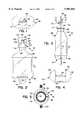
- FIG. 1is a top plan view of a molded container in accordance with the present invention
- FIG. 2is a front elevational view of the molded container of the present invention
- FIG. 3is a side elevational view of the container of FIG. 2;
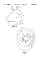
- FIG. 4is a bottom plan view of the container of FIG. 2;
- FIG. 5is a cross-section of the molded container taken generally along the plane 5--5 in FIG. 3;
- FIG. 6is an enlarged fragmentary front elevational view of the cap portion and dispensing nozzle of the container of FIG. 2 with the cap removed therefrom;
- FIG. 7is a enlarged fragmentary top plan view of the cap portion and dispensing nozzle of the container of FIG. 2 with the cap removed therefrom;
- FIG. 8is a fragmentary schematic diagram, partly in section, generally illustrating the apparatus of the present invention for molding, filling and sealing the container of FIGS. 1-4 and, more particularly, the parison extrusion step of the method of the present invention for molding, filling and sealing the container of FIGS. 1-4;
- FIG. 9is another fragmentary schematic diagram, partly in section, generally illustrating the apparatus of the present invention and the step wherein a blowing and filing nozzle is introduced to form and fill the container body;
- FIG. 10is yet another fragmentary schematic diagram, partly in section, illustrating the apparatus of the present invention and, more particularly, the step wherein the main seal mold halves are brought together to form the cap portion of the container and a mandrel is introduced for forming the frangible web and lugs around the container dispensing nozzle;
- FIG. 11is an enlarged fragmentary schematic diagram, partly in section, of the mandrel and main seal mold assembly as illustrated in FIG. 10;
- FIG. 12is an enlarged fragmentary plan view of the top surface of the main seal mold assembly depicted in FIG. 11 with the mandrel retracted therefrom and the parison removed therefrom;
- FIG. 13is an enlarged fragmentary vertical cross-section of a portion of the top surface of the main seal mold assembly illustrated in FIG. 11;
- FIG. 14is yet another fragmentary schematic diagram, partly in section, illustrating the apparatus of the present invention and, more particularly, the step of the method of the present invention wherein the mandrel is removed therefrom;
- FIG. 15is a further fragmentary schematic diagram, partly in section, illustrating the step of the method of the present invention wherein the auxiliary seal mold halves are brought together to mold the container closure;
- FIG. 16is an enlarged fragmentary schematic diagram, partly in section, of the main and auxiliary seal mold assemblies in their respective closed position as illustrated in FIG. 15;
- FIG. 17is a fragmentary schematic diagram, partly in section, illustrating the apparatus of the present invention and, more particularly, the step wherein all of the mold assemblies are opened to allow removal of the completed container.
- the container of the invention and the apparatus of this invention for making the containerwill be described in a normal (upright) operating position and terms such as upper, lower, horizontal, etch, will be used with reference to this position. It will be understood, however, that the container and apparatus of this invention may be manufactured, stored, transported, used, and sold in an orientation other than the position described.
- the apparatus of this inventionhas certain conventional drive and control mechanisms the details of which are described in detail in U.S. Pat. No. 4,707,966 to Weiler et al. and further will be apparent to those having skill in the art and an understanding of the necessary functions of such mechanisms.
- the method of this inventionincludes certain conventional steps, the details of which are also disclosed in U.S. Pat. No. 4,707,966 to Weiler et al. and further will be apparent to those having skill in the art and an understanding of the necessary steps of such method.
- thermoplastic container structure embodying the present inventionwill first be described. This will be followed by a description of an apparatus and method for molding, filling, and sealing the container.
- FIGS. 1-4A formed, filled, and hermetically sealed container 50 of the present invention is illustrated in FIGS. 1-4.
- the container 50is preferably fabricated from conventional thermoplastic molding materials such as polyethylene (low or high density), polypropylene, and the like materials compatible with the container contents.
- Container 50is an example of one such container and includes a hollow body portion 52 having a bottom surface 54 and a top 56, a cap portion 72 that terminates in a dispensing nozzle 76, and a closure portion 92 that seals dispensing nozzle 76.
- the container bottom 54includes two humped end surfaces 58 and 60 and a flat surface or land 62 therebetween.
- a generally U-shaped support ring 64extends outwardly away from the flat surface 62.
- the ring 64is disposed generally co-planar with the mold parting line 67 (FIG. 3) of container 50.
- the top 56 of container body portion 52terminates in a neck 66 unitary therewith which includes a generally cylindrical throat 68 defining a hollow passageway 70 (FIG. 6) for dispensing container contents.
- Cap portion 72terminates in cap portion 72 unitary therewith.
- Cap portion 72is provided with dispensing nozzle 76 which, in turn, is sealed by closure portion 92.
- Cap portion 72, nozzle 76 and closure portion 92are unitary with one another, but closure portion 92 is removable from dispensing nozzle 76 upon fracture of a frangible web that removably connects closure portion 92 to dispensing nozzle 76.
- a grip tab 96 in the shape of an inverted "U"surrounds the closure portion 92.
- Tab 96includes two spaced apart wings 98 and 100 and a bridge 102 therebetween.
- Bridge 102is unitary with and extends generally longitudinally above the top of closure portion 92.
- Wings 98 and 100are unitary with opposite ends of the bridge 102 and extend generally vertically downwardly therefrom.
- Wings 98 and 100terminate in an inclined end surface 104 spaced from and positioned generally adjacent and parallel to the frustoconical base 74 of cap portion 72.
- Each of the wings 98 and 100also includes an inner surface 106 spaced from and positioned generally adjacent and parallel to the dispensing nozzle 76.
- cap portion 72includes a substantially frustoconical base 74 unitary with throat 68 and a generally cylindrical dispensing nozzle 76 unitary with and extending in a direction away from the base 74.
- Dispensing nozzle 76includes an inner surface 78, an outer surface 79 and a top peripheral surface 80.
- Inner surface 78defines an open, axial passageway in communication with a passageway 82 in base 74 which in turn is in communication with the passageway 70 and the hollow body portion 52 of container 50.
- Inner surface 78 of dispensing nozzle 76is tapered inwardly from the top end 80 towards the base 74 so as to receive and seat a draining spike.
- a lip 84extends radially and circumferentially outwardly from the outer surface 79 of dispensing nozzle 76 about the top open distal end 80 thereof which defines an axial access aperture.
- a pair of diametrically opposed ear-shaped locking lugs 88 and 90extend radially outwardly from the lip 84.
- closure portion 92is unitary with nozzle 76.
- closure portion 92includes a bottom circumferential edge 93 (FIG. 5) which is unitary with the lip 84 and lugs 88 and 90 on dispensing nozzle 76.
- the lip 84 and lugs 88 and 90are delineated from the bottom circumferential edge 93 of closure portion 92 by a frangible web 94 which is unitary with dispensing nozzle 76 and closure portion 92 and which surrounds the peripheral edge of lip 84 and lugs 88 and 90.
- closure portion 92is severed and removed from the nozzle 76 by grasping the wings 98 and 100 of tab 96 and then exerting a simultaneous twisting and lifting motion to the closure portion 92 so as to break frangible web 94.
- a LuerTM fitting or a draining spike(not shown) may be secured to nozzle 76.
- Lugs 88 and 90 on dispensing nozzle 76are sized to engage the LuerTM lock threads of such a LuerTM fitting and the inner surface 78 of dispensing nozzle 76 is adapted to receive a draining spike.
- the inner passageway defined by surface 78has controlled dimensions as will be discussed in greater detail hereinbelow.
- FIGS. 8-17show the apparatus and progressively illustrate the sequence of the steps of the method of container fabrication.
- the method of forming the container 50is initiated at an extruder head 110 of conventional design which is adapted to extrude length of parison 112 in the form of a elongated, hollow tube of a semimolten thermoplastic material.
- a mold assembly 200is positioned in spaced relationship from and around the extruded parison 112.
- the mold assembly 200includes a lower main mold assembly 202 including a pair of main coacting mold halves 204 and 206, a seal mold assembly 207 including a main seal mold assembly 208 having a pair of coacting main seal mold halves 210 and 212, and an auxiliary seal mold assembly 214 having a pair of coacting auxiliary seal mold halves 216 and 218.
- Main seal mold assembly 208 and auxiliary seal mold assembly 214may be parts of the same assembly or may be separate seal mold assemblies, as desired.
- Main seal mold halves 210 and 212are positioned above and in sliding engagement with the tops of the main mold halves 204 and 206. Main seal mold halves 210 and 212 are laterally movable relative to and independent of the main mold halves 204 and 206.
- Auxiliary seal mold halves 216 and 218are positioned above and in sliding relationship with the main seal mold halves 210 and 212 of main seal mold assembly 208. Auxiliary seal mold halves 216 and 218 are movable independently of the main seal mold halves 210 and 212 and also independently of the main mold halves 204 and 206.
- the mold assembly 200may include a plurality of mold assemblies aligned in a row and that a plurality of extruder heads 110 may be provided in a row for extruding a length of parison between each of the mold assemblies.
- parison 112is initially extruded and depends vertically downwardly between each of the mold assemblies 202, 208 and 214.
- the main mold halves 204 and 206are then moved together from the main mold open position illustrated in FIG. 8 to the main mold closed position illustrated in FIG. 9 by suitable means, such as a pneumatic or hydraulic actuator or actuators (not illustrated).
- the main mold halves 204 and 206cooperate when moved together to define a body cavity 220 and a top cylindrical opening 221 (FIG. 8).
- the upper end of the parison 112 extending above the seal mold assemblies 208 and 214is gripped by vacuum operable jaws 222 and 224. With the upper end of the parison 112 prevented from collapsing by the holding jaws 222 and 224, a segment of parison 112 is then severed as illustrated in FIG. 9 above the holding jaws 222 and 224 by means of a moving cutter means, such as a hot wire, blade, or the like (not illustrated).
- a moving cutter meanssuch as a hot wire, blade, or the like (not illustrated).
- a blowing and filling assembly 228 including a mandrel 229 and a nozzle 230is moved into registry with the opening at the upper end of the severed segment of parison 112 and thereafter extended downwardly into the opening at the upper end of the severed segment of parison 112.
- the nozzle 230is then positioned abutting the opening 221 in the top of closed main mold assembly 202.
- Mandrel 229preferably includes a conventional blowing tube and a conventional filling tube (neither being visible in FIG. 9).
- gas under pressuresuch as air or the like, is then discharged through the mandrel blowing tube and the nozzle 230 into the interior of parison 112 to expand the parison segment 112 outwardly against the walls of the cavity 220 defined by the main mold assembly 202 to mold the sidewall of container body portion 52, the container bottom 54, the ring 64, and the neck 66.
- the filling tube inside the composite mandrel 229is reciprocated downwardly to open a vent passage in the mandrel 229 to permit venting of the compressed gas out of the molded container.
- the blowing tubeis moved downwardly a small amount within the mandrel 229 to open a product dispensing valve and permit the product to be injected under pressure from the filling tube, through the nozzle 230 and into the formed container body portion 52.
- the composite mandrel 229is withdrawn from the open end of the segment of parison 112.
- cap cavity 232includes an inner frustoconical surface 234 and an inner cylindrical surface 236 unitary with and extending upwardly from surface 234.
- the inner surfaces 234 and 236also include an axial groove 237 (FIG. 9).
- the segment of parison 112 between seal mold halves 210 and 212engages the surfaces 234 and 236 of cavity 232 when the mold halves 210 and 212 are closed to define and mold the frustoconical base 74 and dispensing nozzle 76, respectively, of cap portion 72. Moreover, when the main seal mold halves 210 and 212 are closed, the groove 237 is filled with the thermoplastic material that constitutes parison 112 to define and mold the peripheral edges of wings 98 and 100 of grip tab 96.
- the main seal mold halves 210 and 212also cooperate when moved together to define a top horizontal surface 238.
- the inner cylindrical surface 236 of main seal mold assembly 208terminates at the top surface 238 (FIG. 12) to define a generally circular opening 239 with a circumferential edge 240.
- the top surface 238includes a generally horizontal recessed surface 242 (FIG. 13) which extends radially outwardly from, and circumferentially around, the edge 240.
- the surface 242is co-planar with the top of opening 239 defined by inner cylindrical surface 236.
- a sidewall 244extends generally outwardly and axially away from the end of recessed surface 242 opposite the end thereof connected to edge 240. Sidewall 244 also extends circumferentially around edge 240.
- a sidewall 248extends radially and angularly outwardly and downwardly from the end of top wall 246 opposite the end thereof connected to sidewall 244. Sidewall 248 likewise extends circumferentially around edge 240. Moreover, a generally horizontal surface 250 extends radially outwardly from the end of sidewall 248 opposite the end thereof connected to top wall 246. Surface 250 also extends circumferentially around edge 240. Surface 250 is generally parallel to surfaces 242 and 246 but is spaced axially and radially therefrom.
- the sidewall 248 and surface 250define a closure edge cavity 262 extending circumferentially around edge 240 of opening 239 and radially outwardly from the periphery of knife edge 260.
- Surface 242 and sidewall 244define an annular cavity 252 including a ring-shaped portion 254 which extends circumferentially around edge 240 of opening 239 and two opposed ears 256 and 258 that extend radially outwardly from the periphery of ring-shaped portion 254.
- Knife edge 260forms the frangible web for the container and is spaced from the edge 240 of opening 239 and extends circumferentially around annular cavity 252 and, more particularly, extends around the peripheral edge of the ring-shaped portion 254 and ears 258 and 260 of annular cavity 252.
- Knife edge 260may include any other suitable configuration including the configuration where sidewalls 244 and 248 extend angularly outwardly from the surface 238 and converge above the surface 238 to define a knife point.
- a forming assembly 264 including a mandrel 266is moved into registry with the opening at the upper end of the severed segment of parison 112 and thereafter extended downwardly into the open upper end thereof.
- the mandrel 266includes a base 268 having a lower flat radial surface 270 and a frustoconical molding member 272 unitary with and extending away from the radial surface 270 in a direction opposite the base 268.
- Molding member 272includes an outer frustoconical surface 274 which converges in the direction away from the radial surface 270.
- Mandrel 266is extended downwardly into the open upper end of parison 112 and is positioned such that the radial surface 270 of base 268 abuts and urges against the parison 112 over the top surface 238 of main seal mold assembly 208 and, more particularly, against the parison 112 overlying the knife edge 260 and the annular and closure edge cavities 252 and 262, respectively.
- the pressing actionforces the parison 112 against the top wall 246 of knife edge 260 which, in turn, causes a substantial reduction in the thickness of the parison 112 being pressed against the knife edge 260.
- the segment of parison 112 overlying the knife edge 260is almost but not quite severed and thus the frangible web 94 (FIG. 5) of container 50 is formed.
- Urging of the parison 112 against the top surface 238 of main seal mold assembly 208also causes the thermoplastic material of parison 112 to fill the annular cavity 252 so as to mold the lip 84 and lugs 88 and 90 of cap portion 72.
- the ring shaped portion 254 of annular cavity 252molds the lip 84 of cap portion 72 while the ears 256 and 258 of cavity 252 mold the lugs 88 and 90 of cap portion 72, respectively.
- the urging of the parison 112 against the top surface 238 of main seal mold assembly 208also causes the thermoplastic material of parison 112 to fill the closure edge cavity 262 to mold the bottom circumferential edge 93 of closure 92 (FIG. 5).
- the molding member 272 of forming assembly 264(FIG. 11) is inserted into the opening 239 in the top surface 238 of main seal mold assembly 208 and the parison 112 abutting the inner surface 236 of main seal mold assembly 208 is pressed against the inner surface 236 to form and mold the controlled inside diameter surface 78 of cap portion 72.
- Closure cavity 276includes a closure-complementary inner surface 277 for molding the side wall of closure 92 and sealing the closure 92 to the cap portion 72, and a tab cavity 278, located centrally above and in communication with the closure cavity 276 for molding the bridge 102 of grip tab 96.
- the top cavity 278is defined by opposed flat axial inner surfaces 279 and 280 on auxiliary seal mold halves 216 and 218 respectively. Knife edges 282 and 284 extend radially outwardly from the inner surfaces 279 and 280 respectively of tab cavity 278 for forming a frangible web 286 along the top edge of grip tab 96.
- the three mold assemblies 202, 208 and 214are opened as illustrated in FIG. 17 and the formed, filled and sealed container 50 may be removed and deflashed by suitable convention means.
- the projecting parison flash(at the bottom of the container 50, around the sides of the container, and the upwardly extending portion 288 of the parison 112 above the grip tab 96 of closure 92 is broken away at the frangible web 286 to provide a deflashed container substantially as illustrated in FIGS. 1-4.
Landscapes
- Engineering & Computer Science (AREA)
- Mechanical Engineering (AREA)
- Ceramic Engineering (AREA)
- Blow-Moulding Or Thermoforming Of Plastics Or The Like (AREA)
- Moulds For Moulding Plastics Or The Like (AREA)
- Closures For Containers (AREA)
- Medical Preparation Storing Or Oral Administration Devices (AREA)
Abstract
Description
Claims (7)
Priority Applications (10)
| Application Number | Priority Date | Filing Date | Title |
|---|---|---|---|
| US08/637,944US5901865A (en) | 1996-04-23 | 1996-04-23 | Hermetically sealed container with frangible web and locking lugs and method and apparatus for making same |
| AU17837/97AAU727375B2 (en) | 1996-04-23 | 1997-04-10 | Hermetically sealed container with frangible web and locking lugs and method and apparatus for making same |
| CN97113013ACN1081577C (en) | 1996-04-23 | 1997-04-22 | Hermetically sealed container with frangible web and locking lugs and method and apparatus for making same |
| DE69725207TDE69725207T3 (en) | 1996-04-23 | 1997-04-23 | Hermetically sealed container with breakable tape and closure tabs, and method and apparatus for making same |
| EP97302784AEP0803443B2 (en) | 1996-04-23 | 1997-04-23 | Hermetically sealed container with frangible web and locking lugs and method and apparatus for making same |
| DE69738001TDE69738001T3 (en) | 1996-04-23 | 1997-04-23 | Hermetically sealed container with breakable tape and closure tabs, and method and apparatus for making same |
| JP10601897AJP4434328B2 (en) | 1996-04-23 | 1997-04-23 | Hermetic seal container with brittle web and fixed lugs and method and apparatus for manufacturing the same |
| EP03012888AEP1362685B2 (en) | 1996-04-23 | 1997-04-23 | Hermetically sealed container with frangible web and locking lugs and method and apparatus for making same |
| US09/309,920US6168413B1 (en) | 1996-04-23 | 1999-05-11 | Apparatus for making a hermetically sealed container with frangible web and locking lugs |
| US09/736,638US6381926B1 (en) | 1996-04-23 | 2000-12-14 | Hermetically sealed container with frangible web and locking lugs and method and apparatus for making same |
Applications Claiming Priority (1)
| Application Number | Priority Date | Filing Date | Title |
|---|---|---|---|
| US08/637,944US5901865A (en) | 1996-04-23 | 1996-04-23 | Hermetically sealed container with frangible web and locking lugs and method and apparatus for making same |
Related Child Applications (1)
| Application Number | Title | Priority Date | Filing Date |
|---|---|---|---|
| US09/309,920DivisionUS6168413B1 (en) | 1996-04-23 | 1999-05-11 | Apparatus for making a hermetically sealed container with frangible web and locking lugs |
Publications (1)
| Publication Number | Publication Date |
|---|---|
| US5901865Atrue US5901865A (en) | 1999-05-11 |
Family
ID=24558004
Family Applications (3)
| Application Number | Title | Priority Date | Filing Date |
|---|---|---|---|
| US08/637,944Expired - LifetimeUS5901865A (en) | 1996-04-23 | 1996-04-23 | Hermetically sealed container with frangible web and locking lugs and method and apparatus for making same |
| US09/309,920Expired - LifetimeUS6168413B1 (en) | 1996-04-23 | 1999-05-11 | Apparatus for making a hermetically sealed container with frangible web and locking lugs |
| US09/736,638Expired - LifetimeUS6381926B1 (en) | 1996-04-23 | 2000-12-14 | Hermetically sealed container with frangible web and locking lugs and method and apparatus for making same |
Family Applications After (2)
| Application Number | Title | Priority Date | Filing Date |
|---|---|---|---|
| US09/309,920Expired - LifetimeUS6168413B1 (en) | 1996-04-23 | 1999-05-11 | Apparatus for making a hermetically sealed container with frangible web and locking lugs |
| US09/736,638Expired - LifetimeUS6381926B1 (en) | 1996-04-23 | 2000-12-14 | Hermetically sealed container with frangible web and locking lugs and method and apparatus for making same |
Country Status (6)
| Country | Link |
|---|---|
| US (3) | US5901865A (en) |
| EP (2) | EP1362685B2 (en) |
| JP (1) | JP4434328B2 (en) |
| CN (1) | CN1081577C (en) |
| AU (1) | AU727375B2 (en) |
| DE (2) | DE69738001T3 (en) |
Cited By (19)
| Publication number | Priority date | Publication date | Assignee | Title |
|---|---|---|---|---|
| US6068148A (en)* | 1998-05-26 | 2000-05-30 | Automatic Liquid Packaging, Inc. | Hermetically sealed container including a nozzle with a sealing bead |
| USD456507S1 (en) | 2001-07-20 | 2002-04-30 | Lemarr Stephen Todd | Nebulizer vials |
| USD463290S1 (en) | 2001-06-15 | 2002-09-24 | The Dannon Company, Inc. | Bottle with cap |
| US6626308B2 (en) | 2001-01-26 | 2003-09-30 | Weiler Engineering, Inc. | Hermetically sealed container with self-draining closure |
| US20040059354A1 (en)* | 2002-09-20 | 2004-03-25 | Smith Kevin W. | Surgical fastener particularly for the treatment of gastroesophageal reflux disease (GERD) |
| US20040154269A1 (en)* | 2002-11-22 | 2004-08-12 | Transcoject Gesellschaft Fur Medizinische Gerate Mbh & Co. Kg | System, device and method for the manufacture and handling of a substantially pure object |
| US20040182883A1 (en)* | 2003-03-20 | 2004-09-23 | Weiler Gerhard H. | Hermetically sealed container with non-drip opening |
| US20070138215A1 (en)* | 2005-12-21 | 2007-06-21 | Holopack International Corp. | Dispensing container with nipple dispensing head |
| US7866514B1 (en) | 2006-03-01 | 2011-01-11 | Bernd Hansen | Container and device for production of such container |
| US20110174665A1 (en)* | 2007-04-27 | 2011-07-21 | Daiwa Can Company | Polyester Resin Container With Fracturable Portion And Its Production Method |
| US20130146499A1 (en)* | 2010-07-20 | 2013-06-13 | Bernd Hansen | Method and device for producing and filling containers made of thermoplastic plastic and containers produced in such a way |
| US20140231456A1 (en)* | 2010-06-28 | 2014-08-21 | Unicep Packaging, Inc. | Dispenser with twist lock fitting |
| WO2015036536A1 (en)* | 2013-09-12 | 2015-03-19 | Fresenius Kabi Deutschland Gmbh | Ampoule for medical liquid and method for producing an ampoule |
| WO2016032814A1 (en)* | 2014-08-25 | 2016-03-03 | Weiler Engineering, Inc. | Hermetically sealed, liquid containing ampoule |
| US20160200484A1 (en)* | 2015-01-14 | 2016-07-14 | Weiler Engineering, Inc. | Ampoule with dual luer fitting |
| KR20170070116A (en)* | 2014-10-14 | 2017-06-21 | 헥사곤 라우포스 아에스 | Method and equipment for production of a pinch line free liner |
| US20170197069A1 (en)* | 2014-07-22 | 2017-07-13 | Bayer Animal Health Gmbh | Tube with application tip |
| US9867973B2 (en) | 2013-06-17 | 2018-01-16 | Medline Industries, Inc. | Skin antiseptic applicator and methods of making and using the same |
| WO2023137167A1 (en)* | 2022-01-13 | 2023-07-20 | Koska Family Limited | Systems and methods for rotary blow-fill-seal (bfs) machine mold positioning |
Families Citing this family (18)
| Publication number | Priority date | Publication date | Assignee | Title |
|---|---|---|---|---|
| DE10050660B4 (en) | 2000-10-13 | 2018-06-28 | Robert Bosch Gmbh | Method and device for producing containers filled and sealed with sterile products |
| US6619516B2 (en)* | 2002-02-05 | 2003-09-16 | Weiler Engineering, Inc. | Hermetically sealed container with unitary drop-dispenser |
| WO2004033954A2 (en)* | 2002-10-07 | 2004-04-22 | Becton, Dickinson And Company | Method for filling a container having at least one flexible component |
| US7040497B2 (en)* | 2003-08-26 | 2006-05-09 | Weiler Engineering, Inc. | Hermetically sealed container with child safety overcap |
| US20090101672A1 (en)* | 2005-12-20 | 2009-04-23 | Alpla-Werke Alwin Lehner Gmbh & Co. Kg | Semifinished product for producing a plastic tube and tube of plastic produced from it |
| DE502006008536D1 (en) | 2006-09-15 | 2011-01-27 | Alpla Werke | PREFORM AND METHOD FOR PRODUCING PLASTIC BOTTLES |
| JP4986876B2 (en)* | 2008-02-02 | 2012-07-25 | ヒタチグローバルストレージテクノロジーズネザーランドビーブイ | Disk drive device |
| JP4811428B2 (en)* | 2008-04-25 | 2011-11-09 | 株式会社デンソー | Insert molding method |
| EP2143543A1 (en)* | 2008-07-07 | 2010-01-13 | Nestec S.A. | Device and method for packaging a liquid food product |
| CN101596941B (en)* | 2009-07-03 | 2011-07-27 | 阳江喜之郎果冻制造有限公司 | Air-exhausting bag clamping device with straw packaging bag and packaging method using same |
| US8486324B2 (en) | 2010-07-23 | 2013-07-16 | Automatic Liquid Packaging Solutions Llc | Method and apparatus for producing tiered containers |
| CH704965A1 (en)* | 2011-05-16 | 2012-11-30 | Alpla Werke | Procedures to ensure the dimensional accuracy of a pour opening in or on a prepared in an extrusion blow molding plastic containers. |
| JP6062638B2 (en)* | 2012-01-31 | 2017-01-18 | キョーラク株式会社 | Infusion bottle |
| WO2013117492A1 (en)* | 2012-02-10 | 2013-08-15 | Nestec S.A. | A method of blowing, filling and capping containers |
| AU2013332053B2 (en)* | 2012-10-16 | 2017-12-21 | Kocher-Plastik Maschinenbau Gmbh | Device for producing container products consisting of plastic materials |
| CN109702991B (en)* | 2019-01-25 | 2023-09-22 | 沂水金誉塑业有限公司 | Plastic drum production facility convenient to blow molding |
| CH717442A1 (en)* | 2020-05-18 | 2021-11-30 | Alpla Werke Alwin Lehner Gmbh & Co Kg | Plastic container. |
| CA3190859A1 (en)* | 2020-08-27 | 2022-03-03 | Dirk HATJE | Systems and methods for the application and sealing of end closures on containers |
Citations (19)
| Publication number | Priority date | Publication date | Assignee | Title |
|---|---|---|---|---|
| US3124273A (en)* | 1964-03-10 | Metallic collapsible tubes having | ||
| US3187966A (en)* | 1963-07-09 | 1965-06-08 | Continental Can Co | Flexible container with snip-off and reseal features |
| US3597793A (en)* | 1969-05-28 | 1971-08-10 | Automatic Liquid Packaging | Bottles and the method and apparatus for forming them |
| US3923179A (en)* | 1973-03-07 | 1975-12-02 | American Hospital Supply Corp | Medical liquid container with tactile sterility indicator and method of testing container |
| US4207990A (en)* | 1979-05-03 | 1980-06-17 | Automatic Liquid Packaging, Inc. | Hermetically sealed container with plural access ports |
| US4402420A (en)* | 1981-12-07 | 1983-09-06 | Extracorporeal Medical Specialties, Inc. | Dual function port cap |
| US4405053A (en)* | 1981-04-27 | 1983-09-20 | Abbott Laboratories | Tamperproof closure system for plastic containers |
| US4467930A (en)* | 1982-04-06 | 1984-08-28 | Baxter Travenol Laboratories, Inc. | Overmolded closure seal |
| US4519513A (en)* | 1982-08-30 | 1985-05-28 | Automatic Liquid Packaging, Inc. | Container having pierceable insert |
| US4529095A (en)* | 1983-08-04 | 1985-07-16 | Gerhard Hansen | Plastic container |
| US4539172A (en)* | 1983-12-16 | 1985-09-03 | Baxter Travenol Laboratories, Inc. | Method of blowmolding a container having an integral inner dispensing outlet |
| US4566613A (en)* | 1982-08-03 | 1986-01-28 | Schering-Prebbles Limited | Multiple opening structure receptacle |
| US4584823A (en)* | 1983-06-06 | 1986-04-29 | Heinz Plastic Mold Co. | Improved method and apparatus for blow molding in a single blow molding operation a controlled drop bottle |
| US4643309A (en)* | 1982-02-08 | 1987-02-17 | Astra Lakemedel Ab | Filled unit dose container |
| US4707966A (en)* | 1981-08-26 | 1987-11-24 | Automatic Liquid Packaging, Inc. | Container with an encapsulated top insert and method and apparatus for making same |
| US4821897A (en)* | 1981-08-26 | 1989-04-18 | Automatic Liquid Packaging, Inc. | Container with insert having a fully or partially encapsulating seal with a frangible web formed against said insert |
| US4886175A (en)* | 1989-04-10 | 1989-12-12 | Merck & Co., Inc. | Bottle and cap closure system |
| US5188250A (en)* | 1992-06-05 | 1993-02-23 | Kraft General Foods, Inc. | Plastic beverage bottle with twist-off closure |
| US5409125A (en)* | 1989-12-11 | 1995-04-25 | Aktiebolaget Astra | Unit dose container |
Family Cites Families (10)
| Publication number | Priority date | Publication date | Assignee | Title |
|---|---|---|---|---|
| US3809276A (en)* | 1972-09-27 | 1974-05-07 | Eyelet Specialty Co | Plastic bottle and cap construction |
| DE2255869C3 (en)† | 1972-11-15 | 1982-02-11 | Gerhard 7166 Sulzbach-Laufen Hansen | Device for manufacturing a container from a heat-sealable plastic tube |
| US4176153A (en)* | 1978-02-10 | 1979-11-27 | Automatic Liquid Packaging, Inc. | Unitary, hermetically-sealed but pierceable dispensing container |
| DE3033821C2 (en)* | 1980-09-09 | 1982-09-09 | Gerhard 7166 Sulzbach-Laufen Hansen | Method and device for producing a container from a heat-sealable plastic tube and containers produced by the method and by means of the device |
| US4596110A (en)* | 1981-08-26 | 1986-06-24 | Automatic Liquid Packaging, Inc. | Container with insert having a fully or partially encapsulating seal with a frangible web formed against said insert |
| US4671763A (en)* | 1983-06-29 | 1987-06-09 | Automatic Liquid Packaging, Inc. | Container with a unitary but removable closure and method and apparatus therefor |
| DE68907384T2 (en)* | 1988-06-10 | 1993-10-14 | Becton Dickinson Co | Roller bottle with an enlarged surface. |
| US5054267A (en)* | 1990-08-06 | 1991-10-08 | Graham Engineering Corporation | Apparatus sealing blow molded bottle |
| US5121856A (en)* | 1990-11-30 | 1992-06-16 | Automatic Liquid Packaging, Inc. | Sleeved dispensing vial |
| US5351462A (en)* | 1993-06-02 | 1994-10-04 | Automatic Liquid Packaging, Inc. | Method and apparatus for installing an insert to seal a container |
- 1996
- 1996-04-23USUS08/637,944patent/US5901865A/ennot_activeExpired - Lifetime
- 1997
- 1997-04-10AUAU17837/97Apatent/AU727375B2/ennot_activeExpired
- 1997-04-22CNCN97113013Apatent/CN1081577C/ennot_activeExpired - Lifetime
- 1997-04-23JPJP10601897Apatent/JP4434328B2/ennot_activeExpired - Lifetime
- 1997-04-23EPEP03012888Apatent/EP1362685B2/ennot_activeExpired - Lifetime
- 1997-04-23DEDE69738001Tpatent/DE69738001T3/ennot_activeExpired - Lifetime
- 1997-04-23DEDE69725207Tpatent/DE69725207T3/ennot_activeExpired - Lifetime
- 1997-04-23EPEP97302784Apatent/EP0803443B2/ennot_activeExpired - Lifetime
- 1999
- 1999-05-11USUS09/309,920patent/US6168413B1/ennot_activeExpired - Lifetime
- 2000
- 2000-12-14USUS09/736,638patent/US6381926B1/ennot_activeExpired - Lifetime
Patent Citations (20)
| Publication number | Priority date | Publication date | Assignee | Title |
|---|---|---|---|---|
| US3124273A (en)* | 1964-03-10 | Metallic collapsible tubes having | ||
| US3187966A (en)* | 1963-07-09 | 1965-06-08 | Continental Can Co | Flexible container with snip-off and reseal features |
| US3597793A (en)* | 1969-05-28 | 1971-08-10 | Automatic Liquid Packaging | Bottles and the method and apparatus for forming them |
| US3923179A (en)* | 1973-03-07 | 1975-12-02 | American Hospital Supply Corp | Medical liquid container with tactile sterility indicator and method of testing container |
| US4207990A (en)* | 1979-05-03 | 1980-06-17 | Automatic Liquid Packaging, Inc. | Hermetically sealed container with plural access ports |
| US4405053A (en)* | 1981-04-27 | 1983-09-20 | Abbott Laboratories | Tamperproof closure system for plastic containers |
| US4707966A (en)* | 1981-08-26 | 1987-11-24 | Automatic Liquid Packaging, Inc. | Container with an encapsulated top insert and method and apparatus for making same |
| US4821897A (en)* | 1981-08-26 | 1989-04-18 | Automatic Liquid Packaging, Inc. | Container with insert having a fully or partially encapsulating seal with a frangible web formed against said insert |
| US4402420A (en)* | 1981-12-07 | 1983-09-06 | Extracorporeal Medical Specialties, Inc. | Dual function port cap |
| US4643309A (en)* | 1982-02-08 | 1987-02-17 | Astra Lakemedel Ab | Filled unit dose container |
| US4467930A (en)* | 1982-04-06 | 1984-08-28 | Baxter Travenol Laboratories, Inc. | Overmolded closure seal |
| US4566613A (en)* | 1982-08-03 | 1986-01-28 | Schering-Prebbles Limited | Multiple opening structure receptacle |
| US4519513A (en)* | 1982-08-30 | 1985-05-28 | Automatic Liquid Packaging, Inc. | Container having pierceable insert |
| US4584823A (en)* | 1983-06-06 | 1986-04-29 | Heinz Plastic Mold Co. | Improved method and apparatus for blow molding in a single blow molding operation a controlled drop bottle |
| US4529095A (en)* | 1983-08-04 | 1985-07-16 | Gerhard Hansen | Plastic container |
| US4539172A (en)* | 1983-12-16 | 1985-09-03 | Baxter Travenol Laboratories, Inc. | Method of blowmolding a container having an integral inner dispensing outlet |
| US4886175A (en)* | 1989-04-10 | 1989-12-12 | Merck & Co., Inc. | Bottle and cap closure system |
| US5409125A (en)* | 1989-12-11 | 1995-04-25 | Aktiebolaget Astra | Unit dose container |
| US5188250A (en)* | 1992-06-05 | 1993-02-23 | Kraft General Foods, Inc. | Plastic beverage bottle with twist-off closure |
| US5188250B1 (en)* | 1992-06-05 | 1994-07-05 | Kraft Gen Foods Inc | Plastic beverage bottle with twist-off closure |
Cited By (41)
| Publication number | Priority date | Publication date | Assignee | Title |
|---|---|---|---|---|
| US6068148A (en)* | 1998-05-26 | 2000-05-30 | Automatic Liquid Packaging, Inc. | Hermetically sealed container including a nozzle with a sealing bead |
| US6626308B2 (en) | 2001-01-26 | 2003-09-30 | Weiler Engineering, Inc. | Hermetically sealed container with self-draining closure |
| USD463290S1 (en) | 2001-06-15 | 2002-09-24 | The Dannon Company, Inc. | Bottle with cap |
| USD456507S1 (en) | 2001-07-20 | 2002-04-30 | Lemarr Stephen Todd | Nebulizer vials |
| US20040059354A1 (en)* | 2002-09-20 | 2004-03-25 | Smith Kevin W. | Surgical fastener particularly for the treatment of gastroesophageal reflux disease (GERD) |
| US7584591B2 (en) | 2002-11-22 | 2009-09-08 | Transcoject Gmbh & Co. Kg | System, device and method for the manufacture and handling of a substantially pure object |
| US20040154269A1 (en)* | 2002-11-22 | 2004-08-12 | Transcoject Gesellschaft Fur Medizinische Gerate Mbh & Co. Kg | System, device and method for the manufacture and handling of a substantially pure object |
| US20060086066A1 (en)* | 2002-11-22 | 2006-04-27 | Transcoject Gmbh & Co. Kg | System, device and method for the manufacture and handling of a substantially pure object |
| US8308472B2 (en) | 2002-11-22 | 2012-11-13 | Transcoject Gmbh & Co. Kg | Device for the production and/or handling of a highly pure object |
| US20100009022A1 (en)* | 2002-11-22 | 2010-01-14 | Transcoject Gmbh & Co. Kg | Method for the Production and/or Handling of a Highly Pure Object |
| US7185790B2 (en)* | 2003-03-20 | 2007-03-06 | Weiler Engineering, Inc. | Hermetically sealed container with non-drip opening |
| US20040182883A1 (en)* | 2003-03-20 | 2004-09-23 | Weiler Gerhard H. | Hermetically sealed container with non-drip opening |
| US20070138215A1 (en)* | 2005-12-21 | 2007-06-21 | Holopack International Corp. | Dispensing container with nipple dispensing head |
| US7832601B2 (en)* | 2005-12-21 | 2010-11-16 | The Ritedose Corporation | Dispensing container with nipple dispensing head |
| US7866514B1 (en) | 2006-03-01 | 2011-01-11 | Bernd Hansen | Container and device for production of such container |
| US20110174665A1 (en)* | 2007-04-27 | 2011-07-21 | Daiwa Can Company | Polyester Resin Container With Fracturable Portion And Its Production Method |
| US20140231456A1 (en)* | 2010-06-28 | 2014-08-21 | Unicep Packaging, Inc. | Dispenser with twist lock fitting |
| US9302794B2 (en)* | 2010-07-20 | 2016-04-05 | Bernd Hansen | Method for producing and filling containers made of thermoplastic with a container volume displacement step |
| US20130146499A1 (en)* | 2010-07-20 | 2013-06-13 | Bernd Hansen | Method and device for producing and filling containers made of thermoplastic plastic and containers produced in such a way |
| US9867973B2 (en) | 2013-06-17 | 2018-01-16 | Medline Industries, Inc. | Skin antiseptic applicator and methods of making and using the same |
| US10765849B2 (en) | 2013-06-17 | 2020-09-08 | Medline Industries, Inc. | Skin antiseptic applicator and methods of making and using the same |
| US10661064B2 (en) | 2013-06-17 | 2020-05-26 | Medline Industries, Inc. | Skin antiseptic applicator and methods of making and using the same |
| US9999757B2 (en) | 2013-06-17 | 2018-06-19 | Medline Industries, Inc. | Skin antiseptic applicator and methods of making and using the same |
| US10456328B2 (en)* | 2013-09-12 | 2019-10-29 | Fresenius Kabi Deutschland Gmbh | Ampoule for medical liquid and method for producing an ampoule |
| WO2015036536A1 (en)* | 2013-09-12 | 2015-03-19 | Fresenius Kabi Deutschland Gmbh | Ampoule for medical liquid and method for producing an ampoule |
| CN105517909A (en)* | 2013-09-12 | 2016-04-20 | 费森尤斯卡比德国有限公司 | Ampoule for medical liquid and method for producing an ampoule |
| CN105517909B (en)* | 2013-09-12 | 2019-03-19 | 费森尤斯卡比德国有限公司 | Ampoules for medicinal liquids and method of making ampoules |
| KR20160055218A (en)* | 2013-09-12 | 2016-05-17 | 프레제니우스 카비 도이치란트 게엠베하 | Ampoule for medical liquid and method for producing an ampoule |
| US20160220444A1 (en)* | 2013-09-12 | 2016-08-04 | Fresenius Kabi Deutschland Gmbh | Ampoule for medical liquid and method for producing an ampoule |
| AU2014320293B2 (en)* | 2013-09-12 | 2018-03-08 | Fresenius Kabi Deutschland Gmbh | Ampoule for medical liquid and method for producing an ampoule |
| US20170197069A1 (en)* | 2014-07-22 | 2017-07-13 | Bayer Animal Health Gmbh | Tube with application tip |
| US12343491B2 (en) | 2014-07-22 | 2025-07-01 | Elanco Animal Health Gmbh | Tube with application tip |
| US11672962B2 (en)* | 2014-07-22 | 2023-06-13 | Bayer Animal Health Gmbh | Tube with application tip |
| WO2016032814A1 (en)* | 2014-08-25 | 2016-03-03 | Weiler Engineering, Inc. | Hermetically sealed, liquid containing ampoule |
| US20170246791A1 (en)* | 2014-10-14 | 2017-08-31 | Hexagon Raufoss As | Method and equipment for production of a pinch line free liner |
| US10486355B2 (en)* | 2014-10-14 | 2019-11-26 | Hexagon Technology As | Method and equipment for production of a pinch line free liner |
| KR20170070116A (en)* | 2014-10-14 | 2017-06-21 | 헥사곤 라우포스 아에스 | Method and equipment for production of a pinch line free liner |
| US20160200484A1 (en)* | 2015-01-14 | 2016-07-14 | Weiler Engineering, Inc. | Ampoule with dual luer fitting |
| US10363369B2 (en)* | 2015-01-14 | 2019-07-30 | Weiler Engineering, Inc. | Ampoule with dual Luer fitting |
| WO2023137167A1 (en)* | 2022-01-13 | 2023-07-20 | Koska Family Limited | Systems and methods for rotary blow-fill-seal (bfs) machine mold positioning |
| EP4463304A4 (en)* | 2022-01-13 | 2025-06-11 | Koska Family Limited | Systems and methods for rotary blow-fill-seal (bfs) machine mold positioning |
Also Published As
| Publication number | Publication date |
|---|---|
| EP1362685A2 (en) | 2003-11-19 |
| EP1362685A3 (en) | 2004-09-15 |
| EP0803443A2 (en) | 1997-10-29 |
| DE69738001T2 (en) | 2008-05-08 |
| EP1362685B1 (en) | 2007-08-08 |
| EP1362685B2 (en) | 2011-07-27 |
| US6381926B1 (en) | 2002-05-07 |
| EP0803443A3 (en) | 2001-02-28 |
| EP0803443B2 (en) | 2008-04-09 |
| DE69738001D1 (en) | 2007-09-20 |
| JP4434328B2 (en) | 2010-03-17 |
| AU727375B2 (en) | 2000-12-14 |
| DE69725207D1 (en) | 2003-11-06 |
| EP0803443B1 (en) | 2003-10-01 |
| CN1174157A (en) | 1998-02-25 |
| DE69725207T2 (en) | 2004-05-06 |
| US6168413B1 (en) | 2001-01-02 |
| DE69738001T3 (en) | 2012-01-05 |
| CN1081577C (en) | 2002-03-27 |
| AU1783797A (en) | 1997-10-30 |
| DE69725207T3 (en) | 2008-07-10 |
| JPH1052855A (en) | 1998-02-24 |
Similar Documents
| Publication | Publication Date | Title |
|---|---|---|
| US5901865A (en) | Hermetically sealed container with frangible web and locking lugs and method and apparatus for making same | |
| US4671763A (en) | Container with a unitary but removable closure and method and apparatus therefor | |
| AU749384B2 (en) | Hermetically sealed container including a nozzle with a sealing bead | |
| US4176153A (en) | Unitary, hermetically-sealed but pierceable dispensing container | |
| US5158192A (en) | Dispensing bottle with coupling between closure head and screw cap | |
| US4298045A (en) | Dispensing container with plural removable closure means unitary therewith | |
| US5429789A (en) | Plastic container with self-draining feature | |
| US4821897A (en) | Container with insert having a fully or partially encapsulating seal with a frangible web formed against said insert | |
| US4178976A (en) | Unitary, hermetically-sealed but pierceable dispensing container | |
| US4596110A (en) | Container with insert having a fully or partially encapsulating seal with a frangible web formed against said insert | |
| EP1480891B1 (en) | Hermetically sealed container with unitary drop-dispenser | |
| US4540542A (en) | Method for making a container with a unitary but removable closure | |
| CA1319909C (en) | Plastic container with self-draining feature | |
| US4901873A (en) | Container with insert having a fully or partially encapsulating seal with a frangible web formed against said insert | |
| US4239726A (en) | Method for forming, filling and sealing a container having plural closures | |
| EP0627298B1 (en) | Method and apparatus for forming retaining flange around container closure | |
| US4699748A (en) | Container with insert having a fully or partially encapsulating seal with a frangible web formed against said insert | |
| EP0489572A1 (en) | Hermetically sealed vial | |
| US4425294A (en) | Method for molding and filling a dispensing container having one or more removable closure means unitary therewith | |
| CA1228308A (en) | Molded container with a top opening | |
| JP3801281B2 (en) | Bottle pack container molding equipment | |
| JPH0482103B2 (en) |
Legal Events
| Date | Code | Title | Description |
|---|---|---|---|
| AS | Assignment | Owner name:AUTOMATIC LIQUID PACKAGING, INC., ILLINOIS Free format text:ASSIGNMENT OF ASSIGNORS INTEREST;ASSIGNORS:WEILER, GERHARD H.;RAMRAKHYANI, ARJUN;REEL/FRAME:008033/0332 Effective date:19960414 | |
| STCF | Information on status: patent grant | Free format text:PATENTED CASE | |
| FEPP | Fee payment procedure | Free format text:PAT HOLDER NO LONGER CLAIMS SMALL ENTITY STATUS, ENTITY STATUS SET TO UNDISCOUNTED (ORIGINAL EVENT CODE: STOL); ENTITY STATUS OF PATENT OWNER: LARGE ENTITY | |
| REFU | Refund | Free format text:REFUND - SURCHARGE, PETITION TO ACCEPT PYMT AFTER EXP, UNINTENTIONAL (ORIGINAL EVENT CODE: R2551); ENTITY STATUS OF PATENT OWNER: LARGE ENTITY | |
| FPAY | Fee payment | Year of fee payment:4 | |
| FPAY | Fee payment | Year of fee payment:8 | |
| AS | Assignment | Owner name:MORGAN STANLEY SENIOR FUNDING, INC.,NEW YORK Free format text:SECURITY AGREEMENT;ASSIGNORS:PTS ACQUISITION CORP.;PTS INTERMEDIATE HOLDINGS LLC;CARDINAL HEALTH 400, INC.;AND OTHERS;REEL/FRAME:019323/0302 Effective date:20070410 Owner name:MORGAN STANLEY SENIOR FUNDING, INC., NEW YORK Free format text:SECURITY AGREEMENT;ASSIGNORS:PTS ACQUISITION CORP.;PTS INTERMEDIATE HOLDINGS LLC;CARDINAL HEALTH 400, INC.;AND OTHERS;REEL/FRAME:019323/0302 Effective date:20070410 | |
| AS | Assignment | Owner name:CATALENT USA WOODSTOCK, INC., NEW JERSEY Free format text:CHANGE OF NAME;ASSIGNORS:CARDINAL HEALTH 400, INC.;CARDINAL HEALTH 406, LLC;CARDINAL HEALTH 409, INC.;AND OTHERS;REEL/FRAME:019588/0622 Effective date:20070619 Owner name:CATALENT USA PACKAGING, LLC, NEW JERSEY Free format text:CHANGE OF NAME;ASSIGNORS:CARDINAL HEALTH 400, INC.;CARDINAL HEALTH 406, LLC;CARDINAL HEALTH 409, INC.;AND OTHERS;REEL/FRAME:019588/0622 Effective date:20070619 Owner name:CATALENT PHARMA SOLUTIONS, INC., NEW JERSEY Free format text:CHANGE OF NAME;ASSIGNORS:CARDINAL HEALTH 400, INC.;CARDINAL HEALTH 406, LLC;CARDINAL HEALTH 409, INC.;AND OTHERS;REEL/FRAME:019588/0622 Effective date:20070619 Owner name:CATALENT USA PAINTBALL, INC., NEW JERSEY Free format text:CHANGE OF NAME;ASSIGNORS:CARDINAL HEALTH 400, INC.;CARDINAL HEALTH 406, LLC;CARDINAL HEALTH 409, INC.;AND OTHERS;REEL/FRAME:019588/0622 Effective date:20070619 Owner name:CATALENT PHARMA SOLUTIONS, LLC, NEW JERSEY Free format text:CHANGE OF NAME;ASSIGNORS:CARDINAL HEALTH 400, INC.;CARDINAL HEALTH 406, LLC;CARDINAL HEALTH 409, INC.;AND OTHERS;REEL/FRAME:019588/0622 Effective date:20070619 Owner name:CATALENT USA WOODSTOCK, INC.,NEW JERSEY Free format text:CHANGE OF NAME;ASSIGNORS:CARDINAL HEALTH 400, INC.;CARDINAL HEALTH 406, LLC;CARDINAL HEALTH 409, INC.;AND OTHERS;REEL/FRAME:019588/0622 Effective date:20070619 Owner name:CATALENT USA PACKAGING, LLC,NEW JERSEY Free format text:CHANGE OF NAME;ASSIGNORS:CARDINAL HEALTH 400, INC.;CARDINAL HEALTH 406, LLC;CARDINAL HEALTH 409, INC.;AND OTHERS;REEL/FRAME:019588/0622 Effective date:20070619 Owner name:CATALENT PHARMA SOLUTIONS, INC.,NEW JERSEY Free format text:CHANGE OF NAME;ASSIGNORS:CARDINAL HEALTH 400, INC.;CARDINAL HEALTH 406, LLC;CARDINAL HEALTH 409, INC.;AND OTHERS;REEL/FRAME:019588/0622 Effective date:20070619 Owner name:CATALENT USA PAINTBALL, INC.,NEW JERSEY Free format text:CHANGE OF NAME;ASSIGNORS:CARDINAL HEALTH 400, INC.;CARDINAL HEALTH 406, LLC;CARDINAL HEALTH 409, INC.;AND OTHERS;REEL/FRAME:019588/0622 Effective date:20070619 Owner name:CATALENT PHARMA SOLUTIONS, LLC,NEW JERSEY Free format text:CHANGE OF NAME;ASSIGNORS:CARDINAL HEALTH 400, INC.;CARDINAL HEALTH 406, LLC;CARDINAL HEALTH 409, INC.;AND OTHERS;REEL/FRAME:019588/0622 Effective date:20070619 | |
| FPAY | Fee payment | Year of fee payment:12 |