US5901787A - Metal sealing wireline plug - Google Patents
Metal sealing wireline plugDownload PDFInfo
- Publication number
- US5901787A US5901787AUS08/833,318US83331897AUS5901787AUS 5901787 AUS5901787 AUS 5901787AUS 83331897 AUS83331897 AUS 83331897AUS 5901787 AUS5901787 AUS 5901787A
- Authority
- US
- United States
- Prior art keywords
- plug
- seal
- well
- primary sealing
- actuating member
- Prior art date
- Legal status (The legal status is an assumption and is not a legal conclusion. Google has not performed a legal analysis and makes no representation as to the accuracy of the status listed.)
- Expired - Lifetime
Links
- 239000002184metalSubstances0.000titleclaimsabstractdescription27
- 229910052751metalInorganic materials0.000titleclaimsabstractdescription27
- 238000007789sealingMethods0.000titleclaimsdescription31
- 230000004888barrier functionEffects0.000claimsabstractdescription28
- 229910045601alloyInorganic materials0.000claimsdescription4
- 239000000956alloySubstances0.000claimsdescription4
- 229910001069Ti alloyInorganic materials0.000claimsdescription2
- 239000000463materialSubstances0.000claimsdescription2
- 239000007787solidSubstances0.000claims1
- 230000015572biosynthetic processEffects0.000abstract1
- 238000005755formation reactionMethods0.000abstract1
- 230000007246mechanismEffects0.000description10
- 230000003628erosive effectEffects0.000description5
- 239000007789gasSubstances0.000description3
- 230000004048modificationEffects0.000description2
- 238000012986modificationMethods0.000description2
- 230000036316preloadEffects0.000description2
- 230000000717retained effectEffects0.000description2
- 230000003068static effectEffects0.000description2
- 241000282472Canis lupus familiarisSpecies0.000description1
- 238000005299abrasionMethods0.000description1
- 230000009471actionEffects0.000description1
- 229910001026inconelInorganic materials0.000description1
- 238000009434installationMethods0.000description1
- 230000003993interactionEffects0.000description1
- 239000007788liquidSubstances0.000description1
- 230000013011matingEffects0.000description1
- 239000007769metal materialSubstances0.000description1
- 238000000034methodMethods0.000description1
- 239000003129oil wellSubstances0.000description1
- 238000009419refurbishmentMethods0.000description1
Images


Classifications
- E—FIXED CONSTRUCTIONS
- E21—EARTH OR ROCK DRILLING; MINING
- E21B—EARTH OR ROCK DRILLING; OBTAINING OIL, GAS, WATER, SOLUBLE OR MELTABLE MATERIALS OR A SLURRY OF MINERALS FROM WELLS
- E21B23/00—Apparatus for displacing, setting, locking, releasing or removing tools, packers or the like in boreholes or wells
- E21B23/02—Apparatus for displacing, setting, locking, releasing or removing tools, packers or the like in boreholes or wells for locking the tools or the like in landing nipples or in recesses between adjacent sections of tubing
- E—FIXED CONSTRUCTIONS
- E21—EARTH OR ROCK DRILLING; MINING
- E21B—EARTH OR ROCK DRILLING; OBTAINING OIL, GAS, WATER, SOLUBLE OR MELTABLE MATERIALS OR A SLURRY OF MINERALS FROM WELLS
- E21B33/00—Sealing or packing boreholes or wells
- E21B33/10—Sealing or packing boreholes or wells in the borehole
- E21B33/12—Packers; Plugs
- E21B33/1208—Packers; Plugs characterised by the construction of the sealing or packing means
- E21B33/1212—Packers; Plugs characterised by the construction of the sealing or packing means including a metal-to-metal seal element
- E—FIXED CONSTRUCTIONS
- E21—EARTH OR ROCK DRILLING; MINING
- E21B—EARTH OR ROCK DRILLING; OBTAINING OIL, GAS, WATER, SOLUBLE OR MELTABLE MATERIALS OR A SLURRY OF MINERALS FROM WELLS
- E21B33/00—Sealing or packing boreholes or wells
- E21B33/10—Sealing or packing boreholes or wells in the borehole
- E21B33/12—Packers; Plugs
- E21B33/128—Packers; Plugs with a member expanded radially by axial pressure
- E21B33/1285—Packers; Plugs with a member expanded radially by axial pressure by fluid pressure
Definitions
- the present inventionrelates to a plug device which finds application in creating a pressure barrier within a gas or oil well, or the like, by locating within a section of well conduit having an internal profile corresponding to the external profile of the plug.
- the plugWhen installed, the plug creates a metal-to-metal seal between the tool and the well profile which is capable of withstanding high differential pressures. Once installed, the plug can be retrieved and re-installed repeatedly.
- wireline activated plugswhich can be installed within a well in a corresponding well profile and subsequently retrieved.
- plugsuse elastomeric and/or polymeric seal elements as the primary sealing barrier, with a secondary barrier provided by a metal lip seal which is energised by differential pressure across the seal.
- the primary sealis provided by a metal-to-metal seal, using an elastomeric/polymeric seal as an optional secondary seal barrier.
- the metal seal geometrycreates a large contact area between the mating seal faces. This greatly improves the sealing capability of the plug at low and high pressures when exposed to liquids or gases.
- the metal sealis pre-energised prior to locking the plug in the well profile. The stresses trapped by the subsequent locking of the plug provide an effective seal prior to the application of differential pressure. The metal seal is re-usable over many installations and tests.
- a plug for use in an oil or gas well for creation of a pressure barrier within a profiled well conduitcomprising a plug body including a primary sealing barrier formed of a metal material and holding means for holding the body in place in a well.
- said primary sealing barrieris adapted to be energised by pressure applied above said plug body once located in said well conduit.
- said holding meansis adapted to be operable by means of a running tool so as to lock said plug body against axial movement within said well conduit, following energisation of said primary sealing barrier.
- said primary sealing barriercomprises a frusto-conical seal surface located at the forward end of said plug body, adapted sealingly to engage a corresponding frusto-conical surface of the well profile.
- said sealing barrierfurther includes a no-go shoulder located rearwardly of said seal surface and adapted to engage a corresponding shoulder of said well profile so as to limit downward movement of said seal surface relative to said corresponding surface of said well profile.
- said primary sealing barrieris provided by a metal seal element secured to the forward end of said plug body.
- said holding meanscomprises a plurality of radially movable locking members each having a shoulder adapted to lock against a corresponding shoulder in the well profile.
- said plug bodyis generally cylindrical and includes a blind bore extending from its rearward end towards its forward end, and said locking members are located in a corresponding plurality of apertures extending between the interior surface of said blind bore and the exterior surface of said plug body.
- said holding meansfurther comprises an actuating member which is axially slidable within said blind bore of said plug body between a rearward position in which said locking members may be retracted into said apertures and a forward position in which said actuating member urges said locking members radially outwardly to project beyond the outer surface of said plug body.
- an actuating memberwhich is axially slidable within said blind bore of said plug body between a rearward position in which said locking members may be retracted into said apertures and a forward position in which said actuating member urges said locking members radially outwardly to project beyond the outer surface of said plug body.
- said actuating memberis adapted to be engaged by a running tool for setting said plug and by a pulling tool for retrieving said plug after it has been set.
- said plugfurther includes hold down means for retaining said actuating member in its forward position after the plug has been set.
- said hold down meanscomprises an annular member surrounding said actuating member and including a plurality of resiliently biased locking members adapted to engage an exterior surface of said actuating member.
- said annular memberis removably attached to said plug body and is detachable therefrom by means of an upward jar force applied to said actuating member, whereby said actuating member may return to its rearward position allowing the plug to be retrieved from the well.
- said plugfurther includes a secondary sealing barrier formed of an elastomeric or polymeric material.
- said secondary sealing barriercomprises a seal stack surrounding said plug body rearwardly of said primary sealing barrier.
- a method of providing a plug in a well for creation of a pressure barriercomprising providing a plug on a running tool, operating the retraction of a holding means attached to the plug by interaction of the holding means with operating means disposed on the running tool, operating the holding means when the plug is in position, and locking the holding means in place until the plug is to be withdrawn.
- the thickness of the sealing barriercan be altered to vary the amount of preload of the plug and improve the sealing barrier's integrity.
- FIG. 1is a side view, partially in section, of a wireline plug in accordance with the first aspect of the invention
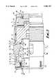
- FIG. 2is a sectional side view of a well profile configured for use with the plug of FIG. 1;
- FIG. 3is a side view, partially in section, of a wireline plug in accordance with a second aspect of the invention.
- FIG. 1shows a wireline plug in accordance with the invention, in which the plug is shown in its "set" position.
- the main component of the plugis a key-retainer mandrel 5, to which all of the other components are attached.
- the mandrel 5is generally cylindrical, having an internal blind bore, closed at the forward end of the mandrel 5.
- a plurality of radially displaceable locking keys 4are located within the bore of the mandrel 5, extending through a corresponding plurality of milled windows or apertures 10 formed in the sides of the mandrel 5.
- the locking keys 4are shown extending out of the windows 10 beyond the external, cylindrical surface of the mandrel 5, in their radially outermost, "locked" position.
- Each of the keys 4includes a shoulder 4A which engages a corresponding shoulder 12 on the inner surface of the mandrel 5, so as to limit the radially outward movement of the keys 5 and prevent them from falling out of the windows 10.
- An actuating membercomprising an expander sleeve 3 is slidably mounted within the mandrel 5 and supports the inner surfaces of the locking keys 4.
- the expander sleeve 3is axially slidable between a rearward position and a forward position as illustrated. In its forward position, the expander sleeve 3 urges the locking keys 4 into their outermost, locked position, as shown.
- a retainer cap 2is attached to the rear end of the mandrel 5 by any suitable means such as a screw thread 2A. The rear end of the expander sleeve 3 extends through an aperture 14 in the retainer cap 2.
- a generally annular hold down mechanism 1is slidably mounted around the rearmost end of the expander sleeve 3, and is located in a counter-bore 16 formed in the rearmost end of the retainer cap 2.
- the hold down mechanism 1is retained within the counter-bore 16 by means of a plurality of shear screws 2B or the like extending radially through the retainer cap 2 and spaced around the circumference thereof.
- a metal primary seal element 7is attached to the forward end of the mandrel 5, suitably by a screw thread 7C, and has a frusto-conical sealing face 7A.
- the metal seal element 7is preferably formed from an alloy having an ultra-high yield strength, most preferably a titanium alloy. The ultra-high yield strength of the element 7 prevents the element from being deformed in use, allowing the plug to be re-used repeatedly without refurbishment of the primary seal.
- the other components of the plugare formed from a suitable alloy, such as inconel.
- a secondary elastomeric or polymeric seal barrieris provided by a seal stack 6, which is located around the body of the mandrel 5 and is retained in position between a shoulder 18 formed on the outer surface of the mandrel 5 and the metal seal element 7.
- the seal stack 6includes an o-ring which seals against the inner surface of the well conduit, in use.
- FIG. 2illustrates a length of well conduit profiled for use with the plug of FIG. 1.
- the plugis attached to a dedicated running tool (not shown) on a string of well servicing tools (not shown).
- Running tools of this general typeare well known in the art and their structure and operation will not be described in detail herein.
- dogs on the running toolengage a fishneck 3A on the interior surface of the expander sleeve 3.
- a bearing shoulder 3B on the exterior surface of the expander sleeve 3is brought into contact with the retainer cap 2 by sliding the expander sleeve 3 towards its rearmost position. This allows the locking keys 4 to be retracted into the mandrel 5.
- the running toolis then pinned, using shear pins (not shown), to hold the plug components in this position.
- the plugis lowered into the well conduit on the string of well servicing tools until the sealing face 7A of the metal seal 7 is brought into contact with a corresponding seal face 30 of the well profile.
- Hydraulic pressureis then applied above the plug, generating a force which energises the metal seal 7 until a no-go shoulder 7B, extending around the metal seal 7 rearwardly of the seal face 7A, bottoms out on a corresponding shoulder 32 of the well profile.
- each locking key 4locks against a corresponding shoulder 36 of the well profile. This maintains the plug completely static within the well profile, preventing fretting or wear of the plug components.
- the hold down mechanismincludes a plurality of balls 1A located in drilled holes 20 which break through into the bore of the hold down mechanism 1.
- the balls 1Aare held in place by springs and grubscrews 1B.
- the surfaces of the balls 1Atouch the exterior surface of the expander sleeve 3.
- the balls 1Amove backwards into the drilled holes 20 against spring pressure. Any attempt to pull the expander sleeve 3 upwards (rearwards) traps the balls 1A between the expander sleeve 3 and the drilled holes 20. This locks the expander sleeve 3 in place behind the locking keys 4, preventing inadvertent release or release by vibration.
- a specially designed running tool(not shown) attached to the toolstring is pinned and engaged with the fishneck 3A of the expander sleeve 3.
- the expander mandrel 5is driven down with the running tool by combined application of pressure and downward jarring.
- the running toolcan be detached from the fishneck 3A.
- a pulling tool(not shown) on the string of well servicing tools is latched into the fishneck 3A of the expander sleeve 3.
- Upward jarring applied by means of the pulling toolshears the shear screws 2B securing the hold down mechanism 1 to the retainer cap 2.
- the expander sleeve 3is pulled upwards (rearwards) from beneath the locking keys 4, until the bearing shoulder 3B reaches the retainer cap 2.
- the unsupported keys 4are then free to move inwards, pushed by the chamfers 4B on the upper edges of the keys 4, which mate with the corresponding shoulder 36 of the well profile as previously described.
- FIG. 3shows a modified wireline plug in accordance with the invention, in which the plug is shown in its "set" position.
- the plug of FIG. 3shares many common features with that of FIG. 1, and the same reference signs have been used to indicate the same components in the two plugs.
- the hold down mechanism of the plug in FIG. 3differs in that there is no separate annular member 1. Instead the ball 1A and spring 1B clutch mechanism which holds the expander sleeve 3A in place within the mandrel 5 is mounted in drilled holes 20 which are formed directly within the retainer cap 2. Retractable pins 22 which extend radially through the retainer cap 2 are provided to hold back the balls 1A of the clutch mechanism during assembly, so that the retainer cap 2 may be slid over the exterior surface of the expander sleeve 3.
- One or more locking screws 24are provided in the retainer cap 2 to pre-tension the threaded connection 2A between the retainer cap 2 and mandrel 5, so that the connection does not become loose during operation.
- One or more locking screws 26are provided in the primary seal element 7 to lock the threaded connection 7C between the primary seal element 7 and mandrel 5.
- An erosion target 40is shown at the lower end of the plug.
- the erosion target 40protects the primary seal element from erosion or abrasion in use and is connected to the primary seal element 7 by a threaded connection 46.
- a locking screw 42pre-tensions the threaded connection 46, so that the connection does not become loose during operation.
- a seal 44is provided around the erosion target 40 to seal between the target and the well profile.
- An erosion targetmay also be used with the wireline plug shown in FIG. 1.
- the plug in accordance with the inventionoffers a primary metal seal.
- Prior systemsuse a secondary metal seal with a primary elastomeric/polymeric seal.
- the seal contact areais large, making it more resistant to damage. Existing systems use point seals. By increasing the length of the metal seal face, the seal contact area can be increased.
- the metal sealis so designed that no permanent deformation occurs while it is pre-loaded. As the metal seal never enters a plastic deformation phase, the whole of the available strain energy is presented for sealing at all times during its life period, i.e. it has a 100% "memory”.
Landscapes
- Life Sciences & Earth Sciences (AREA)
- Engineering & Computer Science (AREA)
- Geology (AREA)
- Mining & Mineral Resources (AREA)
- Physics & Mathematics (AREA)
- Environmental & Geological Engineering (AREA)
- Fluid Mechanics (AREA)
- General Life Sciences & Earth Sciences (AREA)
- Geochemistry & Mineralogy (AREA)
- Pipe Accessories (AREA)
Abstract
Description
Claims (15)
Priority Applications (1)
| Application Number | Priority Date | Filing Date | Title |
|---|---|---|---|
| US08/833,318US5901787A (en) | 1995-06-09 | 1997-04-04 | Metal sealing wireline plug |
Applications Claiming Priority (2)
| Application Number | Priority Date | Filing Date | Title |
|---|---|---|---|
| US48904395A | 1995-06-09 | 1995-06-09 | |
| US08/833,318US5901787A (en) | 1995-06-09 | 1997-04-04 | Metal sealing wireline plug |
Related Parent Applications (1)
| Application Number | Title | Priority Date | Filing Date |
|---|---|---|---|
| US48904395AContinuation-In-Part | 1995-06-09 | 1995-06-09 |
Publications (1)
| Publication Number | Publication Date |
|---|---|
| US5901787Atrue US5901787A (en) | 1999-05-11 |
Family
ID=23942179
Family Applications (1)
| Application Number | Title | Priority Date | Filing Date |
|---|---|---|---|
| US08/833,318Expired - LifetimeUS5901787A (en) | 1995-06-09 | 1997-04-04 | Metal sealing wireline plug |
Country Status (1)
| Country | Link |
|---|---|
| US (1) | US5901787A (en) |
Cited By (67)
| Publication number | Priority date | Publication date | Assignee | Title |
|---|---|---|---|---|
| US6425444B1 (en)* | 1998-12-22 | 2002-07-30 | Weatherford/Lamb, Inc. | Method and apparatus for downhole sealing |
| US6446323B1 (en) | 1998-12-22 | 2002-09-10 | Weatherford/Lamb, Inc. | Profile formation |
| US6457533B1 (en) | 1997-07-12 | 2002-10-01 | Weatherford/Lamb, Inc. | Downhole tubing |
| US6510896B2 (en) | 2001-05-04 | 2003-01-28 | Weatherford/Lamb, Inc. | Apparatus and methods for utilizing expandable sand screen in wellbores |
| US6550539B2 (en) | 2001-06-20 | 2003-04-22 | Weatherford/Lamb, Inc. | Tie back and method for use with expandable tubulars |
| US6578630B2 (en) | 1999-12-22 | 2003-06-17 | Weatherford/Lamb, Inc. | Apparatus and methods for expanding tubulars in a wellbore |
| US20030111267A1 (en)* | 2000-06-28 | 2003-06-19 | Pia Giancarlo T. | Drill bits |
| US6585053B2 (en) | 2001-09-07 | 2003-07-01 | Weatherford/Lamb, Inc. | Method for creating a polished bore receptacle |
| US20030127225A1 (en)* | 2001-12-22 | 2003-07-10 | Harrall Simon John | Bore liner |
| US6591905B2 (en) | 2001-08-23 | 2003-07-15 | Weatherford/Lamb, Inc. | Orienting whipstock seat, and method for seating a whipstock |
| US6598678B1 (en) | 1999-12-22 | 2003-07-29 | Weatherford/Lamb, Inc. | Apparatus and methods for separating and joining tubulars in a wellbore |
| US20030149628A1 (en)* | 2000-02-21 | 2003-08-07 | Oday Abbosh | Ordering items of playable content or other works |
| US20030159673A1 (en)* | 2002-02-22 | 2003-08-28 | King Matthew Brandon | Variable vane rotary engine |
| US6612481B2 (en) | 2001-07-30 | 2003-09-02 | Weatherford/Lamb, Inc. | Wellscreen |
| US6629567B2 (en) | 2001-12-07 | 2003-10-07 | Weatherford/Lamb, Inc. | Method and apparatus for expanding and separating tubulars in a wellbore |
| US6655459B2 (en) | 2001-07-30 | 2003-12-02 | Weatherford/Lamb, Inc. | Completion apparatus and methods for use in wellbores |
| US6662876B2 (en) | 2001-03-27 | 2003-12-16 | Weatherford/Lamb, Inc. | Method and apparatus for downhole tubular expansion |
| US6668930B2 (en) | 2002-03-26 | 2003-12-30 | Weatherford/Lamb, Inc. | Method for installing an expandable coiled tubing patch |
| US6688399B2 (en) | 2001-09-10 | 2004-02-10 | Weatherford/Lamb, Inc. | Expandable hanger and packer |
| US6688395B2 (en) | 2001-11-02 | 2004-02-10 | Weatherford/Lamb, Inc. | Expandable tubular having improved polished bore receptacle protection |
| US6691789B2 (en) | 2001-09-10 | 2004-02-17 | Weatherford/Lamb, Inc. | Expandable hanger and packer |
| US6695065B2 (en) | 2001-06-19 | 2004-02-24 | Weatherford/Lamb, Inc. | Tubing expansion |
| US6695063B2 (en) | 1999-12-22 | 2004-02-24 | Weatherford/Lamb, Inc. | Expansion assembly for a tubular expander tool, and method of tubular expansion |
| US20040045720A1 (en)* | 2002-09-10 | 2004-03-11 | Weatherford/Lamb, Inc. | Tubing expansion tool |
| US6708769B2 (en) | 2000-05-05 | 2004-03-23 | Weatherford/Lamb, Inc. | Apparatus and methods for forming a lateral wellbore |
| US6708767B2 (en) | 2000-10-25 | 2004-03-23 | Weatherford/Lamb, Inc. | Downhole tubing |
| US20040065445A1 (en)* | 2001-05-15 | 2004-04-08 | Abercrombie Simpson Neil Andrew | Expanding tubing |
| US6722441B2 (en) | 2001-12-28 | 2004-04-20 | Weatherford/Lamb, Inc. | Threaded apparatus for selectively translating rotary expander tool downhole |
| US20040074640A1 (en)* | 2000-12-22 | 2004-04-22 | Anderton David Andrew | Method and apparatus |
| US6725917B2 (en) | 2000-09-20 | 2004-04-27 | Weatherford/Lamb, Inc. | Downhole apparatus |
| US6742598B2 (en) | 2002-05-29 | 2004-06-01 | Weatherford/Lamb, Inc. | Method of expanding a sand screen |
| US6752215B2 (en) | 1999-12-22 | 2004-06-22 | Weatherford/Lamb, Inc. | Method and apparatus for expanding and separating tubulars in a wellbore |
| US6752216B2 (en) | 2001-08-23 | 2004-06-22 | Weatherford/Lamb, Inc. | Expandable packer, and method for seating an expandable packer |
| US20040118571A1 (en)* | 2002-12-19 | 2004-06-24 | Lauritzen J. Eric | Expansion assembly for a tubular expander tool, and method of tubular expansion |
| US20040159446A1 (en)* | 2000-10-25 | 2004-08-19 | Weatherford/Lamb, Inc. | Methods and apparatus for reforming and expanding tubulars in a wellbore |
| US6805196B2 (en) | 2000-11-17 | 2004-10-19 | Weatherford/Lamb, Inc. | Expander |
| US6820687B2 (en) | 2002-09-03 | 2004-11-23 | Weatherford/Lamb, Inc. | Auto reversing expanding roller system |
| US20040231843A1 (en)* | 2003-05-22 | 2004-11-25 | Simpson Nell A. A. | Lubricant for use in a wellbore |
| US20040256112A1 (en)* | 2001-09-07 | 2004-12-23 | Harrall Simon J. | Expandable tubulars |
| US20050005668A1 (en)* | 2002-07-11 | 2005-01-13 | Duggan Andrew Michael | Tubing expansion |
| US20050011650A1 (en)* | 1999-12-22 | 2005-01-20 | Weatherford/Lamb Inc. | Method and apparatus for expanding and separating tubulars in a wellbore |
| US20050023001A1 (en)* | 2003-07-09 | 2005-02-03 | Hillis David John | Expanding tubing |
| US20050045342A1 (en)* | 2000-10-25 | 2005-03-03 | Weatherford/Lamb, Inc. | Apparatus and method for completing a wellbore |
| US6877553B2 (en) | 2001-09-26 | 2005-04-12 | Weatherford/Lamb, Inc. | Profiled recess for instrumented expandable components |
| US20050092490A1 (en)* | 2000-10-19 | 2005-05-05 | Weatherford/Lamb, Inc. | Completion apparatus and methods for use in hydrocarbon wells |
| US20050126251A1 (en)* | 2001-08-16 | 2005-06-16 | Peter Oosterling | Apparatus for and a method of expanding tubulars |
| US6932161B2 (en) | 2001-09-26 | 2005-08-23 | Weatherford/Lams, Inc. | Profiled encapsulation for use with instrumented expandable tubular completions |
| US7048050B2 (en) | 1994-10-14 | 2006-05-23 | Weatherford/Lamb, Inc. | Method and apparatus for cementing drill strings in place for one pass drilling and completion of oil and gas wells |
| US20070029082A1 (en)* | 2005-08-05 | 2007-02-08 | Giroux Richard L | Apparatus and methods for creation of down hole annular barrier |
| US7182141B2 (en) | 2002-10-08 | 2007-02-27 | Weatherford/Lamb, Inc. | Expander tool for downhole use |
| US7228901B2 (en) | 1994-10-14 | 2007-06-12 | Weatherford/Lamb, Inc. | Method and apparatus for cementing drill strings in place for one pass drilling and completion of oil and gas wells |
| US7234542B2 (en) | 1994-10-14 | 2007-06-26 | Weatherford/Lamb, Inc. | Methods and apparatus for cementing drill strings in place for one pass drilling and completion of oil and gas wells |
| US20070187113A1 (en)* | 2006-02-15 | 2007-08-16 | Weatherford/Lamb, Inc. | Method and apparatus for expanding tubulars in a wellbore |
| US7264067B2 (en) | 2003-10-03 | 2007-09-04 | Weatherford/Lamb, Inc. | Method of drilling and completing multiple wellbores inside a single caisson |
| US7303022B2 (en) | 2002-10-11 | 2007-12-04 | Weatherford/Lamb, Inc. | Wired casing |
| US7308944B2 (en) | 2003-10-07 | 2007-12-18 | Weatherford/Lamb, Inc. | Expander tool for use in a wellbore |
| US7311148B2 (en) | 1999-02-25 | 2007-12-25 | Weatherford/Lamb, Inc. | Methods and apparatus for wellbore construction and completion |
| US7334650B2 (en) | 2000-04-13 | 2008-02-26 | Weatherford/Lamb, Inc. | Apparatus and methods for drilling a wellbore using casing |
| US7360594B2 (en) | 2003-03-05 | 2008-04-22 | Weatherford/Lamb, Inc. | Drilling with casing latch |
| US7413020B2 (en) | 2003-03-05 | 2008-08-19 | Weatherford/Lamb, Inc. | Full bore lined wellbores |
| US20080260524A1 (en)* | 2005-03-24 | 2008-10-23 | Alstom Technology Ltd | Heat shield for sealing a flow channel of a turbine engine |
| US7730965B2 (en) | 2002-12-13 | 2010-06-08 | Weatherford/Lamb, Inc. | Retractable joint and cementing shoe for use in completing a wellbore |
| US7938201B2 (en) | 2002-12-13 | 2011-05-10 | Weatherford/Lamb, Inc. | Deep water drilling with casing |
| USRE42877E1 (en) | 2003-02-07 | 2011-11-01 | Weatherford/Lamb, Inc. | Methods and apparatus for wellbore construction and completion |
| US20140182863A1 (en)* | 2008-04-09 | 2014-07-03 | Cameron International Corporation | Straight-bore back pressure valve |
| US12158052B2 (en) | 2023-04-07 | 2024-12-03 | Saudi Arabian Oil Company | Flow back option plug assembly |
| US12188326B2 (en) | 2023-04-24 | 2025-01-07 | Saudi Arabian Oil Company | Plug element facilitating well flowback |
Citations (16)
| Publication number | Priority date | Publication date | Assignee | Title |
|---|---|---|---|---|
| US3138207A (en)* | 1960-06-20 | 1964-06-23 | Halliburton Co | Pressure balanced actuating device |
| US3208531A (en)* | 1962-08-21 | 1965-09-28 | Otis Eng Co | Inserting tool for locating and anchoring a device in tubing |
| US4058162A (en)* | 1976-04-22 | 1977-11-15 | Cameron Iron Works, Inc. | Well tool adapted to be locked within and sealed with respect to the bore of the well conduit |
| US4127168A (en)* | 1977-03-11 | 1978-11-28 | Exxon Production Research Company | Well packers using metal to metal seals |
| US4178992A (en)* | 1978-01-30 | 1979-12-18 | Exxon Production Research Company | Metal seal tubing plug |
| US4302018A (en)* | 1980-02-29 | 1981-11-24 | Foster-Miller Associates, Inc. | Packer arrangements for oil wells and the like |
| GB2092206A (en)* | 1981-02-02 | 1982-08-11 | Otis Eng Co | Latch for well tool |
| FR2519687A1 (en)* | 1982-01-12 | 1983-07-18 | Orszagos Koolaj Gazipari | REINSERABLE AND WATERPROOF DEVICE FOR HANGING PROBE FILTER AND TUBING ELEMENT |
| US4651818A (en)* | 1986-05-12 | 1987-03-24 | Exxon Production Research Co. | Metal seal tubing plug |
| US4901794A (en)* | 1989-01-23 | 1990-02-20 | Baker Hughes Incorporated | Subterranean well anchoring apparatus |
| US4907651A (en)* | 1987-12-21 | 1990-03-13 | Texaco Inc. | Metal-to-metal packer seal for downhole disconnectable pipe joint |
| US4969515A (en)* | 1989-12-13 | 1990-11-13 | Otis Engineering Corporation | Expendable devices for well lock system |
| US5066060A (en)* | 1990-04-11 | 1991-11-19 | Otis Engineering Corp. | Running tool |
| GB2272718A (en)* | 1992-11-19 | 1994-05-25 | Masx Energy Services Group Inc | Retrievable whipstock |
| GB2285822A (en)* | 1994-01-19 | 1995-07-26 | Klaas Johannes Zwart | Seal arrangement |
| US5542475A (en)* | 1994-12-01 | 1996-08-06 | Cooper Cameron Corporation | Blanking plug assembly |
- 1997
- 1997-04-04USUS08/833,318patent/US5901787A/ennot_activeExpired - Lifetime
Patent Citations (16)
| Publication number | Priority date | Publication date | Assignee | Title |
|---|---|---|---|---|
| US3138207A (en)* | 1960-06-20 | 1964-06-23 | Halliburton Co | Pressure balanced actuating device |
| US3208531A (en)* | 1962-08-21 | 1965-09-28 | Otis Eng Co | Inserting tool for locating and anchoring a device in tubing |
| US4058162A (en)* | 1976-04-22 | 1977-11-15 | Cameron Iron Works, Inc. | Well tool adapted to be locked within and sealed with respect to the bore of the well conduit |
| US4127168A (en)* | 1977-03-11 | 1978-11-28 | Exxon Production Research Company | Well packers using metal to metal seals |
| US4178992A (en)* | 1978-01-30 | 1979-12-18 | Exxon Production Research Company | Metal seal tubing plug |
| US4302018A (en)* | 1980-02-29 | 1981-11-24 | Foster-Miller Associates, Inc. | Packer arrangements for oil wells and the like |
| GB2092206A (en)* | 1981-02-02 | 1982-08-11 | Otis Eng Co | Latch for well tool |
| FR2519687A1 (en)* | 1982-01-12 | 1983-07-18 | Orszagos Koolaj Gazipari | REINSERABLE AND WATERPROOF DEVICE FOR HANGING PROBE FILTER AND TUBING ELEMENT |
| US4651818A (en)* | 1986-05-12 | 1987-03-24 | Exxon Production Research Co. | Metal seal tubing plug |
| US4907651A (en)* | 1987-12-21 | 1990-03-13 | Texaco Inc. | Metal-to-metal packer seal for downhole disconnectable pipe joint |
| US4901794A (en)* | 1989-01-23 | 1990-02-20 | Baker Hughes Incorporated | Subterranean well anchoring apparatus |
| US4969515A (en)* | 1989-12-13 | 1990-11-13 | Otis Engineering Corporation | Expendable devices for well lock system |
| US5066060A (en)* | 1990-04-11 | 1991-11-19 | Otis Engineering Corp. | Running tool |
| GB2272718A (en)* | 1992-11-19 | 1994-05-25 | Masx Energy Services Group Inc | Retrievable whipstock |
| GB2285822A (en)* | 1994-01-19 | 1995-07-26 | Klaas Johannes Zwart | Seal arrangement |
| US5542475A (en)* | 1994-12-01 | 1996-08-06 | Cooper Cameron Corporation | Blanking plug assembly |
Non-Patent Citations (2)
| Title |
|---|
| European Search Report dated Aug. 14, 1997.* |
| Partial European Search Report (EP 95 30 4034), 4 pps.* |
Cited By (140)
| Publication number | Priority date | Publication date | Assignee | Title |
|---|---|---|---|---|
| US7234542B2 (en) | 1994-10-14 | 2007-06-26 | Weatherford/Lamb, Inc. | Methods and apparatus for cementing drill strings in place for one pass drilling and completion of oil and gas wells |
| US7048050B2 (en) | 1994-10-14 | 2006-05-23 | Weatherford/Lamb, Inc. | Method and apparatus for cementing drill strings in place for one pass drilling and completion of oil and gas wells |
| US7228901B2 (en) | 1994-10-14 | 2007-06-12 | Weatherford/Lamb, Inc. | Method and apparatus for cementing drill strings in place for one pass drilling and completion of oil and gas wells |
| US6457533B1 (en) | 1997-07-12 | 2002-10-01 | Weatherford/Lamb, Inc. | Downhole tubing |
| US7168497B2 (en) | 1998-12-22 | 2007-01-30 | Weatherford/Lamb, Inc. | Downhole sealing |
| US6742606B2 (en)* | 1998-12-22 | 2004-06-01 | Weatherford/Lamb, Inc. | Method and apparatus for drilling and lining a wellbore |
| US6543552B1 (en) | 1998-12-22 | 2003-04-08 | Weatherford/Lamb, Inc. | Method and apparatus for drilling and lining a wellbore |
| US20050127673A1 (en)* | 1998-12-22 | 2005-06-16 | Simpson Neil Andrew A. | Tubing seal |
| US20040216878A1 (en)* | 1998-12-22 | 2004-11-04 | Weatherford/Lamb, Inc. | Method and apparatus for drilling and lining a wellbore |
| US20040149454A1 (en)* | 1998-12-22 | 2004-08-05 | Weatherford/Lamb, Inc. | Downhole sealing |
| US20040226723A1 (en)* | 1998-12-22 | 2004-11-18 | Weatherford/Lamb, Inc. | Procedures and equipment for profiling and jointing of pipes |
| US6446323B1 (en) | 1998-12-22 | 2002-09-10 | Weatherford/Lamb, Inc. | Profile formation |
| US7367404B2 (en) | 1998-12-22 | 2008-05-06 | Weatherford/Lamb, Inc. | Tubing seal |
| US20030132032A1 (en)* | 1998-12-22 | 2003-07-17 | Weatherford/Lamb, Inc. | Method and apparatus for drilling and lining a wellbore |
| US6702030B2 (en) | 1998-12-22 | 2004-03-09 | Weatherford/Lamb, Inc. | Procedures and equipment for profiling and jointing of pipes |
| US7124826B2 (en) | 1998-12-22 | 2006-10-24 | Weatherford/Lamb, Inc. | Procedures and equipment for profiling and jointing of pipes |
| US7117957B2 (en) | 1998-12-22 | 2006-10-10 | Weatherford/Lamb, Inc. | Methods for drilling and lining a wellbore |
| US6527049B2 (en) | 1998-12-22 | 2003-03-04 | Weatherford/Lamb, Inc. | Apparatus and method for isolating a section of tubing |
| US20040079528A1 (en)* | 1998-12-22 | 2004-04-29 | Weatherford/Lamb, Inc. | Tubing anchor |
| US6976539B2 (en) | 1998-12-22 | 2005-12-20 | Weatherford/Lamb, Inc. | Tubing anchor |
| US20050252662A1 (en)* | 1998-12-22 | 2005-11-17 | Weatherford/Lamb, Inc. | Apparatus and method for expanding a tubular |
| US6457532B1 (en) | 1998-12-22 | 2002-10-01 | Weatherford/Lamb, Inc. | Procedures and equipment for profiling and jointing of pipes |
| US6425444B1 (en)* | 1998-12-22 | 2002-07-30 | Weatherford/Lamb, Inc. | Method and apparatus for downhole sealing |
| US6688400B2 (en) | 1998-12-22 | 2004-02-10 | Weatherford/Lamb, Inc. | Downhole sealing |
| US7124821B2 (en) | 1998-12-22 | 2006-10-24 | Weatherford/Lamb, Inc. | Apparatus and method for expanding a tubular |
| US6923261B2 (en) | 1998-12-22 | 2005-08-02 | Weatherford/Lamb, Inc. | Apparatus and method for expanding a tubular |
| US7311148B2 (en) | 1999-02-25 | 2007-12-25 | Weatherford/Lamb, Inc. | Methods and apparatus for wellbore construction and completion |
| US6902000B2 (en) | 1999-12-22 | 2005-06-07 | Weatherford/Lamb, Inc. | Apparatus and methods for expanding tubulars in a wellbore |
| US7373990B2 (en) | 1999-12-22 | 2008-05-20 | Weatherford/Lamb, Inc. | Method and apparatus for expanding and separating tubulars in a wellbore |
| US6899181B2 (en) | 1999-12-22 | 2005-05-31 | Weatherford/Lamb, Inc. | Methods and apparatus for expanding a tubular within another tubular |
| US6578630B2 (en) | 1999-12-22 | 2003-06-17 | Weatherford/Lamb, Inc. | Apparatus and methods for expanding tubulars in a wellbore |
| US20040173355A1 (en)* | 1999-12-22 | 2004-09-09 | Weatherford/Lamb, Inc. | Apparatus and methods for expanding tubulars in a wellbore |
| US6712142B2 (en) | 1999-12-22 | 2004-03-30 | Weatherford/Lamb, Inc. | Apparatus and methods for expanding tubulars in a wellbore |
| US6851475B2 (en) | 1999-12-22 | 2005-02-08 | Weatherford/Lamb, Inc. | Apparatus and methods for separating and joining tubulars in a wellbore |
| US20050077046A1 (en)* | 1999-12-22 | 2005-04-14 | Weatherford/Lamb, Inc. | Apparatus and methods for separating and joining tubulars in a wellbore |
| US20050011650A1 (en)* | 1999-12-22 | 2005-01-20 | Weatherford/Lamb Inc. | Method and apparatus for expanding and separating tubulars in a wellbore |
| US20050155771A1 (en)* | 1999-12-22 | 2005-07-21 | Weatherford/Lamb, Inc. | Apparatus and methods for expanding tubulars in a wellbore |
| US6695063B2 (en) | 1999-12-22 | 2004-02-24 | Weatherford/Lamb, Inc. | Expansion assembly for a tubular expander tool, and method of tubular expansion |
| US7086478B2 (en) | 1999-12-22 | 2006-08-08 | Weatherford/Lamb, Inc. | Apparatus and methods for expanding tubulars in a wellbore |
| US6752215B2 (en) | 1999-12-22 | 2004-06-22 | Weatherford/Lamb, Inc. | Method and apparatus for expanding and separating tubulars in a wellbore |
| US7004257B2 (en) | 1999-12-22 | 2006-02-28 | Weatherford/Lamb, Inc | Apparatus and methods for separating and joining tubulars in a wellbore |
| US6598678B1 (en) | 1999-12-22 | 2003-07-29 | Weatherford/Lamb, Inc. | Apparatus and methods for separating and joining tubulars in a wellbore |
| US20030149628A1 (en)* | 2000-02-21 | 2003-08-07 | Oday Abbosh | Ordering items of playable content or other works |
| US7334650B2 (en) | 2000-04-13 | 2008-02-26 | Weatherford/Lamb, Inc. | Apparatus and methods for drilling a wellbore using casing |
| US7267175B2 (en) | 2000-05-05 | 2007-09-11 | Weatherford/Lamb, Inc. | Apparatus and methods for forming a lateral wellbore |
| US6708769B2 (en) | 2000-05-05 | 2004-03-23 | Weatherford/Lamb, Inc. | Apparatus and methods for forming a lateral wellbore |
| US20050161222A1 (en)* | 2000-05-05 | 2005-07-28 | Haugen David M. | Apparatus and methods for forming a lateral wellbore |
| US20040159466A1 (en)* | 2000-05-05 | 2004-08-19 | Weatherford/Lamb, Inc. | Apparatus and methods for forming a lateral wellbore |
| US7195085B2 (en) | 2000-06-28 | 2007-03-27 | Weatherford/Lamb, Inc. | Drill bit |
| US20030111267A1 (en)* | 2000-06-28 | 2003-06-19 | Pia Giancarlo T. | Drill bits |
| US20040194953A1 (en)* | 2000-09-20 | 2004-10-07 | Weatherford/Lamb, Inc. | Downhole apparatus |
| US6742591B2 (en) | 2000-09-20 | 2004-06-01 | Weatherford/Lamb, Inc. | Downhole apparatus |
| US6725917B2 (en) | 2000-09-20 | 2004-04-27 | Weatherford/Lamb, Inc. | Downhole apparatus |
| US7182142B2 (en) | 2000-09-20 | 2007-02-27 | Weatherford/Lamb, Inc. | Downhole apparatus |
| US7163057B2 (en) | 2000-10-19 | 2007-01-16 | Weatherford/Lamb, Inc. | Completion apparatus and methods for use in hydrocarbon wells |
| US20080121396A1 (en)* | 2000-10-19 | 2008-05-29 | John Emile Hebert | Completion apparatus and methods for use in hydrocarbon wells |
| US7520328B2 (en) | 2000-10-19 | 2009-04-21 | Weatherford/Lamb, Inc. | Completion apparatus and methods for use in hydrocarbon wells |
| US20050092490A1 (en)* | 2000-10-19 | 2005-05-05 | Weatherford/Lamb, Inc. | Completion apparatus and methods for use in hydrocarbon wells |
| US7090025B2 (en) | 2000-10-25 | 2006-08-15 | Weatherford/Lamb, Inc. | Methods and apparatus for reforming and expanding tubulars in a wellbore |
| US20040159446A1 (en)* | 2000-10-25 | 2004-08-19 | Weatherford/Lamb, Inc. | Methods and apparatus for reforming and expanding tubulars in a wellbore |
| US20050045342A1 (en)* | 2000-10-25 | 2005-03-03 | Weatherford/Lamb, Inc. | Apparatus and method for completing a wellbore |
| US7121351B2 (en) | 2000-10-25 | 2006-10-17 | Weatherford/Lamb, Inc. | Apparatus and method for completing a wellbore |
| US6708767B2 (en) | 2000-10-25 | 2004-03-23 | Weatherford/Lamb, Inc. | Downhole tubing |
| US20040173360A1 (en)* | 2000-10-25 | 2004-09-09 | Weatherford/Lamb, Inc. | Downhole tubing |
| US6805196B2 (en) | 2000-11-17 | 2004-10-19 | Weatherford/Lamb, Inc. | Expander |
| US20040074640A1 (en)* | 2000-12-22 | 2004-04-22 | Anderton David Andrew | Method and apparatus |
| US7073583B2 (en) | 2000-12-22 | 2006-07-11 | E2Tech Limited | Method and apparatus for expanding tubing downhole |
| US7055597B2 (en) | 2001-03-27 | 2006-06-06 | Weatherford/Lamb, Inc. | Method and apparatus for downhole tubular expansion |
| US6662876B2 (en) | 2001-03-27 | 2003-12-16 | Weatherford/Lamb, Inc. | Method and apparatus for downhole tubular expansion |
| US20040149440A1 (en)* | 2001-03-27 | 2004-08-05 | Weatherford/Lamb, Inc. | Method and apparatus for downhole tubular expansion |
| US6832649B2 (en) | 2001-05-04 | 2004-12-21 | Weatherford/Lamb, Inc. | Apparatus and methods for utilizing expandable sand screen in wellbores |
| US6510896B2 (en) | 2001-05-04 | 2003-01-28 | Weatherford/Lamb, Inc. | Apparatus and methods for utilizing expandable sand screen in wellbores |
| US20040065445A1 (en)* | 2001-05-15 | 2004-04-08 | Abercrombie Simpson Neil Andrew | Expanding tubing |
| US7172027B2 (en) | 2001-05-15 | 2007-02-06 | Weatherford/Lamb, Inc. | Expanding tubing |
| US20040154808A1 (en)* | 2001-06-19 | 2004-08-12 | Weatherford/Lamb, Inc. | Tubing expansion |
| US7063149B2 (en) | 2001-06-19 | 2006-06-20 | Weatherford/Lamb, Inc. | Tubing expansion with an apparatus that cycles between different diameter configurations |
| US6695065B2 (en) | 2001-06-19 | 2004-02-24 | Weatherford/Lamb, Inc. | Tubing expansion |
| US6550539B2 (en) | 2001-06-20 | 2003-04-22 | Weatherford/Lamb, Inc. | Tie back and method for use with expandable tubulars |
| US20050016739A1 (en)* | 2001-06-20 | 2005-01-27 | Weatherford/Lamb, Inc. | Tie back and method for use with expandable tubulars |
| US6782953B2 (en) | 2001-06-20 | 2004-08-31 | Weatherford/Lamb, Inc. | Tie back and method for use with expandable tubulars |
| US7032679B2 (en) | 2001-06-20 | 2006-04-25 | Weatherford/Lamb, Inc. | Tie back and method for use with expandable tubulars |
| US6971450B2 (en) | 2001-07-30 | 2005-12-06 | Weatherford/Lamb, Inc. | Completion apparatus and methods for use in wellbores |
| US6655459B2 (en) | 2001-07-30 | 2003-12-02 | Weatherford/Lamb, Inc. | Completion apparatus and methods for use in wellbores |
| US6612481B2 (en) | 2001-07-30 | 2003-09-02 | Weatherford/Lamb, Inc. | Wellscreen |
| US20040065447A1 (en)* | 2001-07-30 | 2004-04-08 | Weatherford/Lamb, Inc. | Completion apparatus and methods for use in wellbores |
| US7174764B2 (en) | 2001-08-16 | 2007-02-13 | E2 Tech Limited | Apparatus for and a method of expanding tubulars |
| US20050126251A1 (en)* | 2001-08-16 | 2005-06-16 | Peter Oosterling | Apparatus for and a method of expanding tubulars |
| US6968896B2 (en) | 2001-08-23 | 2005-11-29 | Weatherford/Lamb, Inc. | Orienting whipstock seat, and method for seating a whipstock |
| US6752216B2 (en) | 2001-08-23 | 2004-06-22 | Weatherford/Lamb, Inc. | Expandable packer, and method for seating an expandable packer |
| US6591905B2 (en) | 2001-08-23 | 2003-07-15 | Weatherford/Lamb, Inc. | Orienting whipstock seat, and method for seating a whipstock |
| US6585053B2 (en) | 2001-09-07 | 2003-07-01 | Weatherford/Lamb, Inc. | Method for creating a polished bore receptacle |
| US7156179B2 (en) | 2001-09-07 | 2007-01-02 | Weatherford/Lamb, Inc. | Expandable tubulars |
| US20070158081A1 (en)* | 2001-09-07 | 2007-07-12 | Harrall Simon J | Expandable tubulars |
| US7387169B2 (en) | 2001-09-07 | 2008-06-17 | Weatherford/Lamb, Inc. | Expandable tubulars |
| US20040256112A1 (en)* | 2001-09-07 | 2004-12-23 | Harrall Simon J. | Expandable tubulars |
| US6688399B2 (en) | 2001-09-10 | 2004-02-10 | Weatherford/Lamb, Inc. | Expandable hanger and packer |
| US6997266B2 (en) | 2001-09-10 | 2006-02-14 | Weatherford/Lamb, Inc. | Expandable hanger and packer |
| US6691789B2 (en) | 2001-09-10 | 2004-02-17 | Weatherford/Lamb, Inc. | Expandable hanger and packer |
| US20050173109A1 (en)* | 2001-09-26 | 2005-08-11 | Weatherford/Lamb, Inc. | Profiled recess for instrumented expandable components |
| US6932161B2 (en) | 2001-09-26 | 2005-08-23 | Weatherford/Lams, Inc. | Profiled encapsulation for use with instrumented expandable tubular completions |
| US6877553B2 (en) | 2001-09-26 | 2005-04-12 | Weatherford/Lamb, Inc. | Profiled recess for instrumented expandable components |
| US7048063B2 (en) | 2001-09-26 | 2006-05-23 | Weatherford/Lamb, Inc. | Profiled recess for instrumented expandable components |
| US6688395B2 (en) | 2001-11-02 | 2004-02-10 | Weatherford/Lamb, Inc. | Expandable tubular having improved polished bore receptacle protection |
| US6629567B2 (en) | 2001-12-07 | 2003-10-07 | Weatherford/Lamb, Inc. | Method and apparatus for expanding and separating tubulars in a wellbore |
| US20030127225A1 (en)* | 2001-12-22 | 2003-07-10 | Harrall Simon John | Bore liner |
| US7475735B2 (en) | 2001-12-22 | 2009-01-13 | Weatherford/Lamb, Inc. | Tubular hanger and method of lining a drilled bore |
| US20070158080A1 (en)* | 2001-12-22 | 2007-07-12 | Harrall Simon J | Tubular hanger and method of lining a drilled bore |
| US7152684B2 (en) | 2001-12-22 | 2006-12-26 | Weatherford/Lamb, Inc. | Tubular hanger and method of lining a drilled bore |
| US6722441B2 (en) | 2001-12-28 | 2004-04-20 | Weatherford/Lamb, Inc. | Threaded apparatus for selectively translating rotary expander tool downhole |
| US20030159673A1 (en)* | 2002-02-22 | 2003-08-28 | King Matthew Brandon | Variable vane rotary engine |
| US6668930B2 (en) | 2002-03-26 | 2003-12-30 | Weatherford/Lamb, Inc. | Method for installing an expandable coiled tubing patch |
| US6742598B2 (en) | 2002-05-29 | 2004-06-01 | Weatherford/Lamb, Inc. | Method of expanding a sand screen |
| US20050005668A1 (en)* | 2002-07-11 | 2005-01-13 | Duggan Andrew Michael | Tubing expansion |
| US8746028B2 (en) | 2002-07-11 | 2014-06-10 | Weatherford/Lamb, Inc. | Tubing expansion |
| US6820687B2 (en) | 2002-09-03 | 2004-11-23 | Weatherford/Lamb, Inc. | Auto reversing expanding roller system |
| US20040045720A1 (en)* | 2002-09-10 | 2004-03-11 | Weatherford/Lamb, Inc. | Tubing expansion tool |
| US7086477B2 (en) | 2002-09-10 | 2006-08-08 | Weatherford/Lamb, Inc. | Tubing expansion tool |
| US7182141B2 (en) | 2002-10-08 | 2007-02-27 | Weatherford/Lamb, Inc. | Expander tool for downhole use |
| US7303022B2 (en) | 2002-10-11 | 2007-12-04 | Weatherford/Lamb, Inc. | Wired casing |
| US7730965B2 (en) | 2002-12-13 | 2010-06-08 | Weatherford/Lamb, Inc. | Retractable joint and cementing shoe for use in completing a wellbore |
| US7938201B2 (en) | 2002-12-13 | 2011-05-10 | Weatherford/Lamb, Inc. | Deep water drilling with casing |
| US20040118571A1 (en)* | 2002-12-19 | 2004-06-24 | Lauritzen J. Eric | Expansion assembly for a tubular expander tool, and method of tubular expansion |
| USRE42877E1 (en) | 2003-02-07 | 2011-11-01 | Weatherford/Lamb, Inc. | Methods and apparatus for wellbore construction and completion |
| US7360594B2 (en) | 2003-03-05 | 2008-04-22 | Weatherford/Lamb, Inc. | Drilling with casing latch |
| US7413020B2 (en) | 2003-03-05 | 2008-08-19 | Weatherford/Lamb, Inc. | Full bore lined wellbores |
| US20040231843A1 (en)* | 2003-05-22 | 2004-11-25 | Simpson Nell A. A. | Lubricant for use in a wellbore |
| US7395857B2 (en) | 2003-07-09 | 2008-07-08 | Weatherford/Lamb, Inc. | Methods and apparatus for expanding tubing with an expansion tool and a cone |
| US20050023001A1 (en)* | 2003-07-09 | 2005-02-03 | Hillis David John | Expanding tubing |
| US7264067B2 (en) | 2003-10-03 | 2007-09-04 | Weatherford/Lamb, Inc. | Method of drilling and completing multiple wellbores inside a single caisson |
| US7308944B2 (en) | 2003-10-07 | 2007-12-18 | Weatherford/Lamb, Inc. | Expander tool for use in a wellbore |
| US7665957B2 (en)* | 2005-03-24 | 2010-02-23 | Alstom Technology Ltd | Heat shield for sealing a flow channel of a turbine engine |
| US20080260524A1 (en)* | 2005-03-24 | 2008-10-23 | Alstom Technology Ltd | Heat shield for sealing a flow channel of a turbine engine |
| US7798225B2 (en) | 2005-08-05 | 2010-09-21 | Weatherford/Lamb, Inc. | Apparatus and methods for creation of down hole annular barrier |
| US20070029082A1 (en)* | 2005-08-05 | 2007-02-08 | Giroux Richard L | Apparatus and methods for creation of down hole annular barrier |
| US20070187113A1 (en)* | 2006-02-15 | 2007-08-16 | Weatherford/Lamb, Inc. | Method and apparatus for expanding tubulars in a wellbore |
| US7503396B2 (en) | 2006-02-15 | 2009-03-17 | Weatherford/Lamb | Method and apparatus for expanding tubulars in a wellbore |
| US20140182863A1 (en)* | 2008-04-09 | 2014-07-03 | Cameron International Corporation | Straight-bore back pressure valve |
| US9422788B2 (en)* | 2008-04-09 | 2016-08-23 | Cameron International Corporation | Straight-bore back pressure valve |
| US12158052B2 (en) | 2023-04-07 | 2024-12-03 | Saudi Arabian Oil Company | Flow back option plug assembly |
| US12188326B2 (en) | 2023-04-24 | 2025-01-07 | Saudi Arabian Oil Company | Plug element facilitating well flowback |
Similar Documents
| Publication | Publication Date | Title |
|---|---|---|
| US5901787A (en) | Metal sealing wireline plug | |
| CA2976815C (en) | Quick connect system for setting tool | |
| AU2009240817B2 (en) | Bi-directional annulus seal | |
| US9133678B2 (en) | Metal annulus seal | |
| US4305565A (en) | Variable position ram lock for blowout preventers | |
| US3029873A (en) | Combination bridging plug and combustion chamber | |
| US8051925B2 (en) | Core barrel assemblies with braking devices | |
| US9151134B2 (en) | Seal assembly and method | |
| US5819854A (en) | Activation of downhole tools | |
| US4949787A (en) | Casing hanger seal locking mechanism | |
| US20030034159A1 (en) | Combined sealing and gripping unit for retrievable packers | |
| US5509476A (en) | Short wellhead plug | |
| US10138698B2 (en) | External locking mechanism for seal energizing ring | |
| GB2060031A (en) | Blowout preventer ram lock | |
| WO2006119129A2 (en) | High pressure expandable packer | |
| US7137452B2 (en) | Method of disabling and locking open a safety valve with releasable flow tube for flapper lockout | |
| US20090065191A1 (en) | Support assembly for downhole tool, downhole tool and method | |
| EP1473435A1 (en) | Automatically actuating locking mechanism for a downhole tool | |
| US8215679B2 (en) | Subsea choke insert locking apparatus | |
| EP0687801B1 (en) | Metal sealing wireline plug | |
| US5247997A (en) | Tubing hanger with a preloaded lockdown | |
| BRPI0903733A2 (en) | improvement in sealing subset and release mechanism applied to separable seal joint |
Legal Events
| Date | Code | Title | Description |
|---|---|---|---|
| AS | Assignment | Owner name:SSR (INTERNATIONAL) LIMITED, UNITED KINGDOM Free format text:ASSIGNMENT OF ASSIGNORS INTEREST;ASSIGNOR:BOYLE, COLIN S.;REEL/FRAME:008769/0821 Effective date:19970809 | |
| AS | Assignment | Owner name:TUBOSCOPE (UK) LTD., UNITED KINGDOM Free format text:ASSIGNMENT OF ASSIGNORS INTEREST;ASSIGNOR:SSR (INTERNATIONAL) LTD.;REEL/FRAME:009039/0227 Effective date:19980116 | |
| FEPP | Fee payment procedure | Free format text:PAYOR NUMBER ASSIGNED (ORIGINAL EVENT CODE: ASPN); ENTITY STATUS OF PATENT OWNER: LARGE ENTITY | |
| STCF | Information on status: patent grant | Free format text:PATENTED CASE | |
| FEPP | Fee payment procedure | Free format text:PAYER NUMBER DE-ASSIGNED (ORIGINAL EVENT CODE: RMPN); ENTITY STATUS OF PATENT OWNER: LARGE ENTITY Free format text:PAYOR NUMBER ASSIGNED (ORIGINAL EVENT CODE: ASPN); ENTITY STATUS OF PATENT OWNER: LARGE ENTITY | |
| CC | Certificate of correction | ||
| FEPP | Fee payment procedure | Free format text:PAT HOLDER NO LONGER CLAIMS SMALL ENTITY STATUS, ENTITY STATUS SET TO UNDISCOUNTED (ORIGINAL EVENT CODE: STOL); ENTITY STATUS OF PATENT OWNER: LARGE ENTITY | |
| FPAY | Fee payment | Year of fee payment:4 | |
| FEPP | Fee payment procedure | Free format text:PAYER NUMBER DE-ASSIGNED (ORIGINAL EVENT CODE: RMPN); ENTITY STATUS OF PATENT OWNER: LARGE ENTITY Free format text:PAYOR NUMBER ASSIGNED (ORIGINAL EVENT CODE: ASPN); ENTITY STATUS OF PATENT OWNER: LARGE ENTITY | |
| FPAY | Fee payment | Year of fee payment:8 | |
| FPAY | Fee payment | Year of fee payment:12 | |
| AS | Assignment | Owner name:NATIONAL OILWELL VARCO UK LIMITED, UNITED KINGDOM Free format text:CHANGE OF NAME;ASSIGNOR:TUBOSCOPE UK LIMITED;REEL/FRAME:025900/0081 Effective date:20110221 |