US5901699A - Heat retentive food service base - Google Patents
Heat retentive food service baseDownload PDFInfo
- Publication number
- US5901699A US5901699AUS08/796,941US79694197AUS5901699AUS 5901699 AUS5901699 AUS 5901699AUS 79694197 AUS79694197 AUS 79694197AUS 5901699 AUS5901699 AUS 5901699A
- Authority
- US
- United States
- Prior art keywords
- core
- bottom wall
- base
- dish
- service base
- Prior art date
- Legal status (The legal status is an assumption and is not a legal conclusion. Google has not performed a legal analysis and makes no representation as to the accuracy of the status listed.)
- Expired - Fee Related
Links
- 235000013305foodNutrition0.000titleclaimsabstractdescription57
- 238000010438heat treatmentMethods0.000claimsabstractdescription43
- 229920003023plasticPolymers0.000claimsabstractdescription28
- 239000004033plasticSubstances0.000claimsabstractdescription28
- 230000006698inductionEffects0.000claimsabstractdescription23
- 238000009413insulationMethods0.000claimsabstractdescription22
- 239000000463materialSubstances0.000claimsabstractdescription14
- OKTJSMMVPCPJKN-UHFFFAOYSA-NCarbonChemical compound[C]OKTJSMMVPCPJKN-UHFFFAOYSA-N0.000claimsabstractdescription9
- 229910002804graphiteInorganic materials0.000claimsabstractdescription9
- 239000010439graphiteSubstances0.000claimsabstractdescription9
- 239000007787solidSubstances0.000claimsabstractdescription9
- 239000000919ceramicSubstances0.000claimsabstractdescription8
- 239000002131composite materialSubstances0.000claimsabstractdescription5
- 239000011521glassSubstances0.000claimsdescription8
- 239000004020conductorSubstances0.000claims1
- 238000000465mouldingMethods0.000abstractdescription22
- 239000002184metalSubstances0.000abstractdescription17
- 229910052751metalInorganic materials0.000abstractdescription17
- 230000008859changeEffects0.000abstractdescription6
- 238000012546transferMethods0.000abstractdescription3
- 239000011162core materialSubstances0.000description75
- 238000000034methodMethods0.000description9
- 230000008569processEffects0.000description8
- 239000007788liquidSubstances0.000description6
- 239000012782phase change materialSubstances0.000description6
- 229920003189Nylon 4,6Polymers0.000description4
- 239000012071phaseSubstances0.000description4
- 238000002360preparation methodMethods0.000description4
- 235000012054mealsNutrition0.000description3
- 230000002093peripheral effectEffects0.000description3
- 229910001220stainless steelInorganic materials0.000description3
- 239000010935stainless steelSubstances0.000description3
- 239000010409thin filmSubstances0.000description3
- 229920003295Radel®Polymers0.000description2
- 229920004738ULTEM®Polymers0.000description2
- 229910010293ceramic materialInorganic materials0.000description2
- 229920000491PolyphenylsulfonePolymers0.000description1
- 229910000831SteelInorganic materials0.000description1
- 241001516476VandaSpecies0.000description1
- 235000021167banquetNutrition0.000description1
- 230000015572biosynthetic processEffects0.000description1
- 230000001351cycling effectEffects0.000description1
- 230000002950deficientEffects0.000description1
- 239000010408filmSubstances0.000description1
- 238000012423maintenanceMethods0.000description1
- 239000007769metal materialSubstances0.000description1
- 150000002739metalsChemical class0.000description1
- 238000012986modificationMethods0.000description1
- 230000004048modificationEffects0.000description1
- 239000002991molded plasticSubstances0.000description1
- 230000000474nursing effectEffects0.000description1
- 238000013021overheatingMethods0.000description1
- 230000035699permeabilityEffects0.000description1
- 230000002035prolonged effectEffects0.000description1
- 239000007790solid phaseSubstances0.000description1
- 125000006850spacer groupChemical group0.000description1
- 239000010959steelSubstances0.000description1
- 238000012360testing methodMethods0.000description1
- 238000010792warmingMethods0.000description1
Images


Classifications
- A—HUMAN NECESSITIES
- A47—FURNITURE; DOMESTIC ARTICLES OR APPLIANCES; COFFEE MILLS; SPICE MILLS; SUCTION CLEANERS IN GENERAL
- A47J—KITCHEN EQUIPMENT; COFFEE MILLS; SPICE MILLS; APPARATUS FOR MAKING BEVERAGES
- A47J36/00—Parts, details or accessories of cooking-vessels
- A47J36/24—Warming devices
- A47J36/2494—Warming devices using heat storage elements or materials, e.g. lava stones
- A—HUMAN NECESSITIES
- A47—FURNITURE; DOMESTIC ARTICLES OR APPLIANCES; COFFEE MILLS; SPICE MILLS; SUCTION CLEANERS IN GENERAL
- A47G—HOUSEHOLD OR TABLE EQUIPMENT
- A47G19/00—Table service
- A47G19/02—Plates, dishes or the like
- A47G19/027—Plates, dishes or the like with means for keeping food cool or hot
Definitions
- the present inventionrelates generally to heat retaining food service containers for keeping food thereon warm prior to service and, more particularly, to heat retentive bases for maintaining a plate with food thereon warm for a period of time.
- rethermalizationIn rethermalization the food is placed on plates on a tray, with the tray placed within a metal cabinet.
- the cabinetincludes heating pads for each tray that correspond in location to the food to be heated on the tray.
- the entire mealis placed on the tray with a plurality of trays stored in the cabinet.
- the cabinetis stored in a refrigerator unit until it is time to reheat and serve the meal.
- a heater control coupled to the cabinet and heating padsis activated to heat only the food on the warming pads thereby keeping the remaining food cold. The heating is accomplished while the cabinet is within the refrigerator unit.
- Another wayis to provide an insulated container, generally consisting of an insulated base or tray with an insulated cover therefor.
- a plate with heated foodis placed on the previously insulated base with the cover placed thereover. The heat from the heated food maintains the food warm within the insulated cover.
- Yet another type of device in useis a heatable base that is likened to a heat sink.
- This type of deviceis effective when all of the food on the plate is to be kept warm.
- the baseis heated to a sufficient temperature whereupon a plate with prepared food is placed upon the heated base and a cover placed thereover.
- the baseis placed in a convection type heating unit or oven to sufficiently heat the base.
- the core of the baseincludes what is known as a phase change material that absorbs heat when heated, and which slowly dissipated the heat thereafter. The dissipating heat is transmitted to the plate situated thereon to keep the food warm.
- a coveris placed over the plate that mates with the base.
- Prior art heatable baseshave included such phase change materials as pure wax, solid phase change materials, and bladders carrying such materials.
- these baseshave been manufactured from plastic and stainless steel.
- Such basesare exemplified in the following U.S. Pat. Ser. Nos.: 2,876,634 issued Mar. 10, 1959 to Zimmerman et al.; 3,054,395 issued Sep. 18, 1962 to Torino, 3,065,744 issued Nov. 27, 1962 to Scavallo; 3,148,676 issued Sep. 15, 1964 to Truog et al.; 3,557,774 issued in 1969 to Kreis; 3,837,330 issued Sep. 24, 1974 to Lanigan et al; 3,874,370 issued Apr. 1, 1975 to Williams; 4,059,096 issued Nov.
- the present inventionis a heat retaining food service base for use with a plate carrying previously prepared food for maintaining the prepared food warm during an extended period of time.
- the food service basecomprises a plastic dish with an integral metal cone having characteristics making the core susceptible to induction heating.
- the metal coreis a solid disk fashioned from steel, however, other configurations and metals may be used.
- the plastic dishis formed around the metal core, preferably by insert molding to provide a one-piece, integral, no seam base.
- the coreis of sufficient mass to heat up to 425-450° F. in approximately ten to fifteen (10-15) seconds by a 2.5-3 kW induction heating unit. Thereafter, the heat acquired by the core slowly dissipates to the food on a plate held on the base. The core maintains heat down to 140° F. for a minimum time of thirty (30) minutes.
- the present massof 0.9 pounds for a base that holds a standard 9" plate was sized to work with a 2.5-3 kW induction heater as the mass will take only ten to fifteen (10-15) seconds to heat to the temperature of 425-450° F. This is the approximate amount of time that a typical food preparation worker has to fix a plate of prepared food. Therefore, the present base is timed to accomplish sufficient heating in the time range.
- the coreIn forming the solid core service base the core is held in the molding position by several pins. The pins are received in apertures disposed in the core. While the core is held in place, the liquid plastic is introduced therearound to form the service base. A central bore in the core allows the liquid plastic to flow to the back side of the core for encasing the core within the service base and to form a wall that becomes the service base bottom. Thereafter, the pins are removed from the service base. Plastic plugs that fit into the core and base apertures are ultrasonically welded to the bottom of the base.
- the solid core service baseis heated by a suitable induction type heating unit. In this manner, the core is sufficiently heated to thereafter slowly dissipate its heat through the wall of the service base and adjacent the bottom of the plate into the plate and food thereon to maintain the warmth of the food.
- a service basein another form, includes a hollow metal disk having a standard wax-type phase change core.
- the hollow metal diskis fashioned from a metal that is characteristically susceptible to heating by induction and preferably a magnetic metal.
- the phase change metal diskis inserted molded integral with the one-piece service base.
- the phase change service baseis heated by induction heating rather than by convection heating.
- magnetic pinshold the phase change disk.
- the service basemay include a plurality of legs to allow the service bases to be stacked upon one another while leaving a minimum air space between bases.
- the one-piece insert molded plastic service baseeliminates any type of stress on seams, joints, or failure points.
- Another alternative core materialis an electrically conductive, but non-metallic material such as graphite or a ceramic and graphite composite. Such materials can improve heat up time and reduce the weight of the unit.
- a thin film of glassmay be added between the core and the dish. Additionally or alternatively, a layer of insulation may be added between the core and the bottom of the service base to keep the bottom of the base cooler than the top of the base. This insulation can be made of glass or air and may optionally include a spacer between the insulation and the core.
- the dishmay be made of a ceramic material, similar to a china plate.
- the core materialmay also be mixed with the ceramic material to form a single solid unit which is susceptible to induction heating.
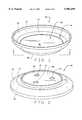
- FIG. 1is a top perspective view of a food service base embodying the present invention
- FIG. 2is a bottom perspective view of the service base of FIG. 1;
- FIG. 3is a sectional view of the service base taken along line 3--3 of FIG. 1;
- FIG. 4is a perspective view of the metallic heat sink for the service base in accordance with the present invention.
- FIG. 5is an enlarged sectional view of the bottom edge of the service base taken along circle 5--5 of FIG. 3;
- FIG. 6is an enlarged sectional view of the bottom plug of the service base taken along circle 6--6 of FIG. 3;
- FIG. 7is a bottom perspective view of a second embodiment of a food service base
- FIG. 8is a side view in partial section of the service base of FIG. 7 without a core
- FIG. 9is a front elevation view in partial section of the service base of FIGS. 7;
- FIG. 10is a front elevation view in partial section of the service base and core respectively of FIGS. 7 and 9;
- FIG. 11is a front elevation view in partial section of stacked service bases of FIG. 7;
- FIG. 12is a sectional view of the service base with a thin film of glass inserted between the core and the dish;
- FIG. 13is a sectional view of the service base with a layer of insulation inserted under the core;
- FIG. 14is a sectional view of the service base of FIG. 13 with an additional separator between the insulation and the core;
- FIG. 15is a sectional view of the service base with an insulating air gap between the bottom of the service base and the core.
- the food service base 20is essentially "bowl-shaped" having an essentially flat bottom area having an upper bottom surface 36 that is annularly surrounded by a first or intermediate upwardly sloping wall 27 that is annularly surrounded by a second or main upwardly sloping wall 22. Disposed at the upper periphery of the wall 22 is an annular rim 24. Disposed at the underside of the base 20 extending from the bottom of the wall 27 is an annular bottom rim 28.
- the base 20is designed to receive a standard serving plate, typically china, with the plate fitting into the cavity 34 defined by the bottom surface 26, annular walls 22, 27, and the upper rim 24.
- the bottom surface 36is adjacent the bottom of the plate (not shown) when the plate is placed in the service base 20.
- the base 20is shown in cross-section. It can be readily seen that the bottom area 26 consists of an upper bottom wall 36 and a lower bottom wall 38 separated by an annular transverse wall 39 that joins the intermediate wall 27.
- the upper and lower bottom walls 36, 38 respectively, and the annular side wall 39define a cavity (not numbered) in which is disposed a core 40.
- the core 40is formed integrally with the molding of the base 20 and is thus surrounded by the walls 36, 38 and 39.
- the base 20is molded from a plastic such as Radel® polyphenylsulfone made by Amoco, a Stanyl Nylon 46, or an Ultem® made by GE. Other impact and high heat resistant engineered plastics may also be used.
- the lower bottom surface 38has three molding apertures 30, 31, 32 that are shown without plugs as a result of the molding process. It should be understood from the following that the molding apertures 30, 31, 32 are filled with plugs after the molding process is complete.
- the core 40is shown.
- the core 40is preferably a disk of sufficient mass and size to cover the bottom of a standard plate.
- the coreis formed of a metal that is at least somewhat electrically conductive such that the core is susceptible to heating by an induction heating unit.
- the core 40may be magnetic as well.
- the core 40includes a center or central bore 42 and three disk apertures 44, 45, 46.
- the center bore 42extends through the disk 40.
- the center bore 42allows the liquid plastic during the molding process to flow behind the disk thereby forming the upper bottom wall 36 of the bottom area 26.
- the disk apertures 44, 45, 46are for receipt of molding pins (not shown) integral with the mold for positioning the core before the actual molding for proper placement and alignment of the core 40 during molding of the service base 20.
- the disk apertures 44, 45, 46may or may not extend through the disk 40.
- FIG. 5shows the juncture of the wall 27 with the walls 36, 38, 39 and the bottom rim 28.
- An alternative materialmay be used for the core 40 which is non-metallic. It must be at least electrically conductive and preferably electrically and magnetically conductive, so that it is still susceptible to induction heating.
- a materialsuch as graphite or a graphite and ceramic composite may be used to lower overall weight of the unit while simultaneously improving the heat up time.
- the lower bottom wall 38 of the bottom area 26 of the base 20has three openings 30, 31, 32 (FIG. 2) corresponding in location to the disk apertures 44, 45, and 46 although FIG. 3 shows only one such aperture 44.
- the molding pins(not shown) create the openings 30, 31, 32 when the pins are extracted after the molding process is complete.
- a plug 50preferably of the same plastic material as the molded service base 20 is placed in the mold aperture 30 after the base 20 is released from the mold.
- the plug 50extends through and into the disk aperture 44.
- the plugis preferably ultrasonically welded. It should be readily understood that a plug is also inserted and ultrasonically welded into the disk apertures 31 and 32.
- the molding of the service base 20is accomplished as follows.
- the disk 40is supported via its disk apertures 44, 45, 46 on and by three pins (not shown) that extend from and are integral with the mold (not shown).
- the pinsthus suspend the core 40 while liquid plastic is injected therearound as per the typical insert molding process. As stated above, some of the liquid plastic flows through the center bore 42 around the back of the core 40 to form the upper bottom wall 36.
- the mold and pinsare removed thereby leaving the molding apertures 30, 31, and 32 as seen in FIG. 2. Thereafter, plugs 50 are ultrasonically welded into the base 20.
- the service base 20is designed to be heated by a suitable induction heating type unit wherein the core 20 may obtain a temperature of 450° F. within approximately ten to fifteen (10-15) seconds. This is accomplished by a 2.5-3 kW induction heating unit.
- the core 40is designed such that it can hold heat for a minimum of thirty (30) minutes without going below 140° F. food temperature as per industry standards.
- the acquired heat by the basedissipates its heat upwards through the bottom of the base, through the plate and into the food thereon. It can thus be seen that the service base 20 is molded as one piece so as to eliminate any seams, joints, or failure points.
- the heat absorbed by the core 40is dissipated through the plastic and into the plate with food thereon (not shown). It has been found that for a 9" plate a core of 0.9 pounds with a circular upper surface corresponding to the size of the bottom on the plate is sufficient.
- FIGS. 7 and 8there is shown an alternative service base generally designated 60. While the service base in FIGS. 7 and 8 does have a core, it is shown without a core for an understanding of the structure of the base 60.
- the base 60again is essentially "bowl-shaped" and includes a bottom wall 62 having an annular downwardly extending rim 64 therearound. Radially extending about the rim 64 is an intermediate annular bottom wall portion 66. Extending form the underside of the wall 66 is a plurality of legs 68. Upwardly extending from the wall 66 is an annular angled wall 70 that terminates in an upstanding peripheral rim 72.
- the base 60is formed of a plastic such as Radel® from Amoco, Stanyl Nylon 46 , or an Ultem® from GE. Also, the base 60 is preferably insert molded.
- the walls 62, 70, 72define an interior space 74 that is configured to receive a standard serving plate (not shown), with the bottom wall 62 designed to be adjacent the lower bottom surface of the plate.
- the base 60may be made of a ceramic similar to a china plate. If a graphite or graphite and ceramic composite is used as the core material, this would allow the core material to be premixed with the material used for the dish. Forming of the service base is then simplified as the base becomes a single solid unit, the core material being dispersed throughout the dish. The entire unit then becomes susceptible to induction heating.
- the core 80consists of an upper and lower metal piece.
- the lower piece 82is of a pie dish shape having a peripheral annular flange 83.
- the upper pieceis a flat disk 84 also having a peripheral annular flange 85 that is adapted to meet and be sealed against the annular flange 83.
- the upper and lower walls 82 and 84thus define an interior cavity 88 in which is received a standard wax phase change material (not shown).
- the walls 82, 84 of the core 80are formed of a metal that is susceptible to induction heating, and is preferably a magnetic metal and electrically conductive. This allows the core 80 to be suspended in the mold during the molding process by magnetic pins (not shown).
- the core 80is shown integrally molded into the base 60.
- the upper piece 84is sized and adapted to be received against the bottom wall 62.
- a lower wall 86is formed around the lower piece 82 of the core 80 to follow the contours thereof.
- the lower wall 86is integrally formed along with the rest of the base 60, and includes an annular "U" flange 87 that is adapted to be matingly received onto the rim 64. In this manner, the core 80 is entrained in the plastic base.
- the bases 60are readily stackable with the leg 68 providing enough air space between the bottom 86 of one base and the upper bottom wall 62 of another base.
- the service base 60is insert molded in similar fashion as the service base 20. However, in the service base 60 magnetic pins are used to hold the core 80 in place because the core 80 includes a phase change material that cannot leak out. The liquid plastic during insert molding is formed around the core 80 such that a one-piece unitary service base 60 is formed.
- the service base 60is raised to a sufficient temperature through a known induction type heating unit to thereafter dissipate its heat to the plate and the food thereon.
- the short induction cycle heatingmay cause somewhat uneven heating of the core, with variances in the core temperature of as much as 100° F. This problem can be overcome as shown in FIG. 12.
- the service base 90is shown. Between the service base 90 and the core 92 is a thin film of insulation 94, preferably made of a glass type. Testing has shown that a film of glass 1/32 inch in thickness slows the heat transfer process to the outer shell just enough to allow the disk temperature to stabilize at a safe temperature without effecting the total holding ability of the base but enough to prevent spot overheating.
- FIG. 13shows a layer of insulation 98 added between the core 92 and a modified second bottom wall 100.
- the modification of the second bottom wall 100allows the extra room for the insulation 98 within the enclosure for the core 92. It is preferable to use a glass type insulation ranging in thickness from 0.03" to 0.25".
- FIG. 14shows a slight deviation to the solution shown in FIG. 13.
- a separator 102is added between the core 92 and the insulation 98. This allows the units without insulation to be retrofitted by using the existing bottom of the unit as the separator 102, and then adding the insulation 98 and a second modified bottom 100.
- an air gap or dead space 108is shown as an alternative method of insulation.
- a specially modified bottom piece 104is used which incorporates a plurality of small projections 106. The projections 106 lift the core 92, maintaining contact between the core 92 and the rest of the service base 90.
Landscapes
- Engineering & Computer Science (AREA)
- Food Science & Technology (AREA)
- Cookers (AREA)
- Table Devices Or Equipment (AREA)
Abstract
Description
Claims (9)
Priority Applications (1)
| Application Number | Priority Date | Filing Date | Title |
|---|---|---|---|
| US08/796,941US5901699A (en) | 1995-09-19 | 1997-02-07 | Heat retentive food service base |
Applications Claiming Priority (2)
| Application Number | Priority Date | Filing Date | Title |
|---|---|---|---|
| US08/530,004US5611328A (en) | 1995-09-19 | 1995-09-19 | Heat retentive food service base |
| US08/796,941US5901699A (en) | 1995-09-19 | 1997-02-07 | Heat retentive food service base |
Related Parent Applications (1)
| Application Number | Title | Priority Date | Filing Date |
|---|---|---|---|
| US08/530,004Continuation-In-PartUS5611328A (en) | 1995-09-19 | 1995-09-19 | Heat retentive food service base |
Publications (1)
| Publication Number | Publication Date |
|---|---|
| US5901699Atrue US5901699A (en) | 1999-05-11 |
Family
ID=46253284
Family Applications (1)
| Application Number | Title | Priority Date | Filing Date |
|---|---|---|---|
| US08/796,941Expired - Fee RelatedUS5901699A (en) | 1995-09-19 | 1997-02-07 | Heat retentive food service base |
Country Status (1)
| Country | Link |
|---|---|
| US (1) | US5901699A (en) |
Cited By (20)
| Publication number | Priority date | Publication date | Assignee | Title |
|---|---|---|---|---|
| WO2002098174A2 (en) | 2001-05-21 | 2002-12-05 | Thermal Solutions, Inc. | Heat retentive inductive-heatable laminated matrix |
| WO2003049504A1 (en)* | 2001-11-29 | 2003-06-12 | Aladdin Temp-Rite, Llc | Heat retentive food tray with cover |
| US20030116560A1 (en)* | 2001-11-29 | 2003-06-26 | Burk Wyatt | Induction insert for insulated trays |
| US20060048768A1 (en)* | 2004-09-08 | 2006-03-09 | Michel Champagne | Dinner plate warmer |
| US20070246037A1 (en)* | 2004-04-30 | 2007-10-25 | Cantu Homaro R | Cooking and serving system and methods |
| US20080047956A1 (en)* | 2006-08-28 | 2008-02-28 | Richard Dudman | Inductively heated warming system |
| US20110011554A1 (en)* | 2007-11-21 | 2011-01-20 | Mathieu Lion | Temperature-retaining device |
| ITVI20100301A1 (en)* | 2010-11-11 | 2012-05-12 | Alina Ivan | THERMAL ACCUMULATOR FOR SUPPORTS AND CONTAINERS FOR FOOD, MEDICAL, CHEMICAL AND SIMILAR USE |
| US8263906B2 (en) | 2010-05-11 | 2012-09-11 | Cambro Manufacturing Company | Food warming system |
| WO2016028678A1 (en)* | 2014-08-18 | 2016-02-25 | Garland Commercial Industries Llc | Graphite composite cooking plate |
| US20160138795A1 (en)* | 2014-10-20 | 2016-05-19 | Numerical Design, Inc. | Microfluidic-based apparatus and method for vaporization of liquids |
| US20160150896A1 (en)* | 2013-07-23 | 2016-06-02 | Probalco Bvba | Plate for serving hot meals thereon |
| US20160205727A1 (en)* | 2014-11-26 | 2016-07-14 | Numerical Design, Inc. | Microfluidic-based apparatus and method vaporization of liquids using magnetic induction |
| US20170303710A1 (en)* | 2014-10-28 | 2017-10-26 | Tempra Technology, Inc. | Heat retaining dish assembly and method of heating same |
| US9854942B2 (en)* | 2011-10-24 | 2018-01-02 | Aladdin Temp-Rite Llc | Induction-based heat retentive server |
| WO2018122471A1 (en)* | 2016-12-28 | 2018-07-05 | Renaud Chantal | Ceramic tableware article having a mineral filler |
| CN108451271A (en)* | 2017-12-14 | 2018-08-28 | 宁波市鄞州下应百益五金厂 | Thermal store and the tableware using the thermal store and the warm hand articles for use using the thermal store |
| USD979342S1 (en)* | 2021-02-18 | 2023-02-28 | Jinho Heo | Plate |
| USD1005781S1 (en) | 2021-01-29 | 2023-11-28 | Duke Manufacturing Co. | Liner for a food holding well |
| US11912465B2 (en) | 2021-01-27 | 2024-02-27 | Duke Manufacturing Co. | Liner for food receiver of food holding apparatus |
Citations (21)
| Publication number | Priority date | Publication date | Assignee | Title |
|---|---|---|---|---|
| US1330209A (en)* | 1920-02-10 | Xcooxing | ||
| US2876634A (en)* | 1954-12-08 | 1959-03-10 | Hale G Zimmerman | Thermodynamic container |
| US3054395A (en)* | 1959-07-15 | 1962-09-18 | Egidio Minuti | Hot plate pot heater |
| US3065744A (en)* | 1961-08-22 | 1962-11-27 | Legion Utensils Company Inc | Plate warmer |
| US3148676A (en)* | 1962-12-10 | 1964-09-15 | Crimsco Inc | Unit for maintaining food at a constant temperature |
| US3557774A (en)* | 1969-01-24 | 1971-01-26 | Kries Ag | Heat storage dish |
| US3766975A (en)* | 1970-09-17 | 1973-10-23 | G Todd | Drinking receptacle |
| US3837330A (en)* | 1973-03-28 | 1974-09-24 | American Hospital Supply Corp | Heat-retaining server |
| US3875370A (en)* | 1974-03-07 | 1975-04-01 | Standex Int Corp | Heat-retaining food service unit |
| US4059096A (en)* | 1976-05-19 | 1977-11-22 | Imperial Arts Corporation | Unitized serving base with imperforate pellet |
| US4086907A (en)* | 1976-09-08 | 1978-05-02 | Caddy Corporation Of America | Heat storage dish |
| US4246884A (en)* | 1979-08-17 | 1981-01-27 | Mcgraw-Edison Company | Plate warmer |
| US4505252A (en)* | 1983-09-09 | 1985-03-19 | American Hospital Supply Corporation | Hollow dishes with meltable cores and method of making such dishes |
| US4567877A (en)* | 1984-07-30 | 1986-02-04 | Bahman Sepahpur | Heat storage food container |
| US4777931A (en)* | 1987-07-07 | 1988-10-18 | Kaltron, Inc. | Platewarmer system |
| US4982722A (en)* | 1989-06-06 | 1991-01-08 | Aladdin Synergetics, Inc. | Heat retentive server with phase change core |
| US5052369A (en)* | 1985-12-13 | 1991-10-01 | Johnson Kendrick A | Heat retaining food container |
| US5125391A (en)* | 1991-10-10 | 1992-06-30 | Servolift Eastern Corporation | Heat-retaining food service container |
| US5417276A (en)* | 1991-11-25 | 1995-05-23 | Dobry; Reuven | Particulate heating/cooling agents |
| US5603858A (en)* | 1995-06-02 | 1997-02-18 | Aladdin Synergetics, Inc. | Heat retentive server for induction heating |
| US5611328A (en)* | 1995-09-19 | 1997-03-18 | Seco Products Corporation | Heat retentive food service base |
- 1997
- 1997-02-07USUS08/796,941patent/US5901699A/ennot_activeExpired - Fee Related
Patent Citations (21)
| Publication number | Priority date | Publication date | Assignee | Title |
|---|---|---|---|---|
| US1330209A (en)* | 1920-02-10 | Xcooxing | ||
| US2876634A (en)* | 1954-12-08 | 1959-03-10 | Hale G Zimmerman | Thermodynamic container |
| US3054395A (en)* | 1959-07-15 | 1962-09-18 | Egidio Minuti | Hot plate pot heater |
| US3065744A (en)* | 1961-08-22 | 1962-11-27 | Legion Utensils Company Inc | Plate warmer |
| US3148676A (en)* | 1962-12-10 | 1964-09-15 | Crimsco Inc | Unit for maintaining food at a constant temperature |
| US3557774A (en)* | 1969-01-24 | 1971-01-26 | Kries Ag | Heat storage dish |
| US3766975A (en)* | 1970-09-17 | 1973-10-23 | G Todd | Drinking receptacle |
| US3837330A (en)* | 1973-03-28 | 1974-09-24 | American Hospital Supply Corp | Heat-retaining server |
| US3875370A (en)* | 1974-03-07 | 1975-04-01 | Standex Int Corp | Heat-retaining food service unit |
| US4059096A (en)* | 1976-05-19 | 1977-11-22 | Imperial Arts Corporation | Unitized serving base with imperforate pellet |
| US4086907A (en)* | 1976-09-08 | 1978-05-02 | Caddy Corporation Of America | Heat storage dish |
| US4246884A (en)* | 1979-08-17 | 1981-01-27 | Mcgraw-Edison Company | Plate warmer |
| US4505252A (en)* | 1983-09-09 | 1985-03-19 | American Hospital Supply Corporation | Hollow dishes with meltable cores and method of making such dishes |
| US4567877A (en)* | 1984-07-30 | 1986-02-04 | Bahman Sepahpur | Heat storage food container |
| US5052369A (en)* | 1985-12-13 | 1991-10-01 | Johnson Kendrick A | Heat retaining food container |
| US4777931A (en)* | 1987-07-07 | 1988-10-18 | Kaltron, Inc. | Platewarmer system |
| US4982722A (en)* | 1989-06-06 | 1991-01-08 | Aladdin Synergetics, Inc. | Heat retentive server with phase change core |
| US5125391A (en)* | 1991-10-10 | 1992-06-30 | Servolift Eastern Corporation | Heat-retaining food service container |
| US5417276A (en)* | 1991-11-25 | 1995-05-23 | Dobry; Reuven | Particulate heating/cooling agents |
| US5603858A (en)* | 1995-06-02 | 1997-02-18 | Aladdin Synergetics, Inc. | Heat retentive server for induction heating |
| US5611328A (en)* | 1995-09-19 | 1997-03-18 | Seco Products Corporation | Heat retentive food service base |
Non-Patent Citations (2)
| Title |
|---|
| Product line catalog for Therma Systems Corporation, South Plainsfield, New Jersey.* |
| Product line catalog for Therma-Systems Corporation, South Plainsfield, New Jersey. |
Cited By (37)
| Publication number | Priority date | Publication date | Assignee | Title |
|---|---|---|---|---|
| EP1393594A4 (en)* | 2001-05-21 | 2007-07-18 | Thermal Solutions Inc | Heat retentive inductive-heatable laminated matrix |
| WO2002098174A2 (en) | 2001-05-21 | 2002-12-05 | Thermal Solutions, Inc. | Heat retentive inductive-heatable laminated matrix |
| WO2003049504A1 (en)* | 2001-11-29 | 2003-06-12 | Aladdin Temp-Rite, Llc | Heat retentive food tray with cover |
| US20030116560A1 (en)* | 2001-11-29 | 2003-06-26 | Burk Wyatt | Induction insert for insulated trays |
| US6670589B2 (en)* | 2001-11-29 | 2003-12-30 | Aladdin Temp-Rite, Llc | Heat retentive food tray with cover |
| US20070246037A1 (en)* | 2004-04-30 | 2007-10-25 | Cantu Homaro R | Cooking and serving system and methods |
| US7690294B2 (en) | 2004-04-30 | 2010-04-06 | Cantu Homaro R | Cooking and serving system and methods |
| US20060048768A1 (en)* | 2004-09-08 | 2006-03-09 | Michel Champagne | Dinner plate warmer |
| US20080047956A1 (en)* | 2006-08-28 | 2008-02-28 | Richard Dudman | Inductively heated warming system |
| US20110011554A1 (en)* | 2007-11-21 | 2011-01-20 | Mathieu Lion | Temperature-retaining device |
| US9247848B2 (en)* | 2007-11-21 | 2016-02-02 | Mastrad, S.A. | Temperature-retaining device |
| US8263906B2 (en) | 2010-05-11 | 2012-09-11 | Cambro Manufacturing Company | Food warming system |
| ITVI20100301A1 (en)* | 2010-11-11 | 2012-05-12 | Alina Ivan | THERMAL ACCUMULATOR FOR SUPPORTS AND CONTAINERS FOR FOOD, MEDICAL, CHEMICAL AND SIMILAR USE |
| US9854942B2 (en)* | 2011-10-24 | 2018-01-02 | Aladdin Temp-Rite Llc | Induction-based heat retentive server |
| US11241117B2 (en)* | 2011-10-24 | 2022-02-08 | Aladdin Temp-Rite Llc | Induction-based heat retentive server |
| US12226052B2 (en)* | 2011-10-24 | 2025-02-18 | Aladdin Temp-Rite, LLP | Induction-based heat retentive server |
| US20220151438A1 (en)* | 2011-10-24 | 2022-05-19 | Aladdin Temp-Rite, Llc | Induction-Based Heat Retentive Server |
| US20160150896A1 (en)* | 2013-07-23 | 2016-06-02 | Probalco Bvba | Plate for serving hot meals thereon |
| US10728961B2 (en) | 2014-08-18 | 2020-07-28 | Garland Commercial Industries Llc | Graphite composite cooking plate |
| WO2016028678A1 (en)* | 2014-08-18 | 2016-02-25 | Garland Commercial Industries Llc | Graphite composite cooking plate |
| AU2015305776B2 (en)* | 2014-08-18 | 2018-04-12 | Garland Commercial Industries Llc | Graphite composite cooking plate |
| EP3183940A4 (en)* | 2014-08-18 | 2018-04-11 | Garland Commercial Industries, LLC | Graphite composite cooking plate |
| US20240191870A1 (en)* | 2014-10-20 | 2024-06-13 | Numerical Design, Inc. | Microfluidic-based apparatus and method for vaporization of liquids |
| US20160138795A1 (en)* | 2014-10-20 | 2016-05-19 | Numerical Design, Inc. | Microfluidic-based apparatus and method for vaporization of liquids |
| US10502409B2 (en)* | 2014-10-20 | 2019-12-10 | Numerical Design, Inc. | Microfluidic-based apparatus and method for vaporization of liquids |
| US12259126B2 (en)* | 2014-10-20 | 2025-03-25 | Numerical Design, Inc. | Microfluidic-based apparatus and method for vaporization of liquids |
| US11141011B2 (en)* | 2014-10-28 | 2021-10-12 | Tempra Technology, Inc. | Heat retaining dish assembly and method of heating same |
| US20170303710A1 (en)* | 2014-10-28 | 2017-10-26 | Tempra Technology, Inc. | Heat retaining dish assembly and method of heating same |
| US20160205727A1 (en)* | 2014-11-26 | 2016-07-14 | Numerical Design, Inc. | Microfluidic-based apparatus and method vaporization of liquids using magnetic induction |
| WO2018122471A1 (en)* | 2016-12-28 | 2018-07-05 | Renaud Chantal | Ceramic tableware article having a mineral filler |
| CN108451271A (en)* | 2017-12-14 | 2018-08-28 | 宁波市鄞州下应百益五金厂 | Thermal store and the tableware using the thermal store and the warm hand articles for use using the thermal store |
| US11912465B2 (en) | 2021-01-27 | 2024-02-27 | Duke Manufacturing Co. | Liner for food receiver of food holding apparatus |
| US12240654B2 (en) | 2021-01-27 | 2025-03-04 | Duke Manufacturing Co. | Liner for food receiver of food holding apparatus |
| USD1005781S1 (en) | 2021-01-29 | 2023-11-28 | Duke Manufacturing Co. | Liner for a food holding well |
| USD1082430S1 (en) | 2021-01-29 | 2025-07-08 | Duke Manufacturing Co. | Liner for food holding well |
| USD1091238S1 (en) | 2021-01-29 | 2025-09-02 | Duke Manufacturing Co. | Liner for a food holding well |
| USD979342S1 (en)* | 2021-02-18 | 2023-02-28 | Jinho Heo | Plate |
Similar Documents
| Publication | Publication Date | Title |
|---|---|---|
| US5611328A (en) | Heat retentive food service base | |
| US5901699A (en) | Heat retentive food service base | |
| TW298585B (en) | ||
| US4567877A (en) | Heat storage food container | |
| US4881590A (en) | Apparatus for cooling, storing and inductively reheating complete meals | |
| JP5025154B2 (en) | Electric rice cooker | |
| US4917076A (en) | Device for keeping warm or cooling foods or beverages | |
| JP3511130B2 (en) | Induction heating tableware, induction heating tableware set and induction heating table set | |
| US20030116560A1 (en) | Induction insert for insulated trays | |
| KR20230106364A (en) | Absorption type food tray with temparature keeping function | |
| GB2272758A (en) | Rotary electric stove | |
| EP0446302A1 (en) | Temperature attenuator to control heating of the contents of a container and method of using the same | |
| US6670589B2 (en) | Heat retentive food tray with cover | |
| JP5316524B2 (en) | Electric rice cooker | |
| JP5846326B1 (en) | Cooking equipment | |
| JP2012040428A (en) | Electric rice cooker | |
| US4825046A (en) | Thermal interface device for heating elements | |
| JP6197167B2 (en) | Electric rice cooker | |
| JP5527459B2 (en) | Electric rice cooker | |
| JPH0534599Y2 (en) | ||
| JP6161585B2 (en) | Electric rice cooker | |
| JP4573451B2 (en) | Steam cooking pot | |
| JP2023099983A (en) | Structure of microwave-safe high-durability, heating and thermal insulation container, and manufacturing method thereof | |
| JPH0317791Y2 (en) | ||
| KR101284941B1 (en) | Cooker with air space part |
Legal Events
| Date | Code | Title | Description |
|---|---|---|---|
| AS | Assignment | Owner name:SECO PRODUCTS CORPORATION, MISSOURI Free format text:ASSIGNMENT OF ASSIGNORS INTEREST;ASSIGNOR:MCDERMOTT, MICHAEL B.;REEL/FRAME:009701/0402 Effective date:19970203 Owner name:SECO PRODUCTS CORPORATION, MISSOURI Free format text:ASSIGNMENT OF ASSIGNORS INTEREST;ASSIGNOR:MCDERMOTT, MICHAEL B.;REEL/FRAME:009387/0450 Effective date:19970203 | |
| AS | Assignment | Owner name:NATIONSBANK, NATIONAL ASSOCIATION, NORTH CAROLINA Free format text:MERGER;ASSIGNOR:BOATMAN'S NATIONAL BANK OF ST. LOUIS, THE;REEL/FRAME:010395/0478 Effective date:19970613 Owner name:SECO PRODUCTS CORPORATION, DISTRICT OF COLUMBIA Free format text:ASSIGNMENT OF ASSIGNORS INTEREST;ASSIGNOR:BANK OF AMERICA, NATIONAL ASSOCIATION;REEL/FRAME:010395/0433 Effective date:19991116 Owner name:BANK OF AMERICA, NATIONAL ASSOCIATION, NORTH CAROL Free format text:CHANGE OF NAME;ASSIGNOR:NATIONSBANK NATIONAL ASSOCIATION;REEL/FRAME:010395/0453 Effective date:19990705 Owner name:BANK OF AMERICA NATIONAL TRUST AND SAVINGS ASSOCIA Free format text:MERGER;ASSIGNOR:BANK OF AMERICA, NATIONAL ASSOCIATION;REEL/FRAME:010395/0773 Effective date:19990723 | |
| AS | Assignment | Owner name:DINEX INTERNATIONAL, INC., CONNECTICUT Free format text:ASSIGNMENT OF ASSIGNORS INTEREST;ASSIGNOR:BANK OF AMERICA;REEL/FRAME:010444/0001 Effective date:19991129 | |
| AS | Assignment | Owner name:CITIZENS BANK OF MASSACHUSETTS, MASSACHUSETTS Free format text:SECURITY AGREEMENT;ASSIGNOR:DINEX INTERNATIONAL, INC.;REEL/FRAME:010958/0262 Effective date:19991118 | |
| FEPP | Fee payment procedure | Free format text:PAT HOLDER NO LONGER CLAIMS SMALL ENTITY STATUS, ENTITY STATUS SET TO UNDISCOUNTED (ORIGINAL EVENT CODE: STOL); ENTITY STATUS OF PATENT OWNER: LARGE ENTITY | |
| REFU | Refund | Free format text:REFUND - SURCHARGE, PETITION TO ACCEPT PYMT AFTER EXP, UNINTENTIONAL (ORIGINAL EVENT CODE: R2551); ENTITY STATUS OF PATENT OWNER: LARGE ENTITY | |
| FPAY | Fee payment | Year of fee payment:4 | |
| AS | Assignment | Owner name:BANK OF AMERICA, N.A., CALIFORNIA Free format text:LETTER AGREEMENT;ASSIGNOR:SECO PRODUCTS CORPORATION;REEL/FRAME:013998/0841 Effective date:19991008 | |
| REMI | Maintenance fee reminder mailed | ||
| LAPS | Lapse for failure to pay maintenance fees | ||
| STCH | Information on status: patent discontinuation | Free format text:PATENT EXPIRED DUE TO NONPAYMENT OF MAINTENANCE FEES UNDER 37 CFR 1.362 |