US5901581A - Paralytic lower limb rehabilitation apparatus - Google Patents
Paralytic lower limb rehabilitation apparatusDownload PDFInfo
- Publication number
- US5901581A US5901581AUS09/092,541US9254198AUS5901581AUS 5901581 AUS5901581 AUS 5901581AUS 9254198 AUS9254198 AUS 9254198AUS 5901581 AUS5901581 AUS 5901581A
- Authority
- US
- United States
- Prior art keywords
- slide rails
- transverse
- slider
- thigh
- longitudinal
- Prior art date
- Legal status (The legal status is an assumption and is not a legal conclusion. Google has not performed a legal analysis and makes no representation as to the accuracy of the status listed.)
- Expired - Fee Related
Links
Images


Classifications
- A—HUMAN NECESSITIES
- A61—MEDICAL OR VETERINARY SCIENCE; HYGIENE
- A61H—PHYSICAL THERAPY APPARATUS, e.g. DEVICES FOR LOCATING OR STIMULATING REFLEX POINTS IN THE BODY; ARTIFICIAL RESPIRATION; MASSAGE; BATHING DEVICES FOR SPECIAL THERAPEUTIC OR HYGIENIC PURPOSES OR SPECIFIC PARTS OF THE BODY
- A61H1/00—Apparatus for passive exercising; Vibrating apparatus; Chiropractic devices, e.g. body impacting devices, external devices for briefly extending or aligning unbroken bones
- A61H1/02—Stretching or bending or torsioning apparatus for exercising
- A61H1/0237—Stretching or bending or torsioning apparatus for exercising for the lower limbs
- A61H1/0255—Both knee and hip of a patient, e.g. in supine or sitting position, the feet being moved together in a plane substantially parallel to the body-symmetrical plane
- A61H1/0259—Both knee and hip of a patient, e.g. in supine or sitting position, the feet being moved together in a plane substantially parallel to the body-symmetrical plane moved by translation
- A—HUMAN NECESSITIES
- A61—MEDICAL OR VETERINARY SCIENCE; HYGIENE
- A61H—PHYSICAL THERAPY APPARATUS, e.g. DEVICES FOR LOCATING OR STIMULATING REFLEX POINTS IN THE BODY; ARTIFICIAL RESPIRATION; MASSAGE; BATHING DEVICES FOR SPECIAL THERAPEUTIC OR HYGIENIC PURPOSES OR SPECIFIC PARTS OF THE BODY
- A61H1/00—Apparatus for passive exercising; Vibrating apparatus; Chiropractic devices, e.g. body impacting devices, external devices for briefly extending or aligning unbroken bones
- A61H1/02—Stretching or bending or torsioning apparatus for exercising
- A61H1/0237—Stretching or bending or torsioning apparatus for exercising for the lower limbs
- A61H1/0244—Hip
Definitions
- Acute cerebral vascular impairmentusually referred to as a cerebral vascular accident
- vertebra impairmentusually cause lower limb paralysis.
- the paralysis of a lower limbusually leads to joint stiffness and muscle atrophy at the hip joint, knee joint and ankle joint due to the lack of passive joint motion, which may even cause bed sores if the patient has been lying down in bed for a very long time.
- the current mechanical rehabilitation deviceperforms only simple bending and extension/retraction exercises for the lower limb. It is not able to facilitate rotation motion for the hip joint, the knee joint and the ankle joint. Thus, as the muscle and joint of the patient's lower limb may not be fully exercised, and the function may be getting worse, the effectiveness of the conventional rehabilitation devices is very limited. Thus, the conventional rehabilitation device can not replace manual rehabilitation effectively.
- the present inventionis related to a rehabilitation apparatus which provides multiple degrees of freedom of motion to assist the paralytic lower limb of a patient having cerebral vascular impairment or vertebra impairment to perform exercise of more degrees of freedom so as to facilitate the rehabilitation of said lower limb.
- This inventionat best, helps the recovery of the limb and, at worst, prevents the condition of the limb from getting worse.
- the rehabilitation apparatus of the present inventionutilizes electricity as a power source to drive the sliding mechanism for performing mechanical displacement to generate a three dimensional motion, the range and speed of which are adjustable, and which helps the hip joint, knee joint and ankle joint of the patient perform passive exercise in the upward and downward directions and the inward and outward directions at proper periods and with proper loads.
- the rehabilitation apparatus of the present inventioncomprises: a transversely movable slider mechanism, a thigh supporting/moving mechanism and a sole supporting/moving mechanism; wherein the transversely movable slider mechanism makes use of a transversely movable slider which incorporates a spherical joint so that it generates a rotational motion to provide clockwise and counterclockwise rotation of the patient's limb; the thigh supporting/moving mechanism supports the thigh and makes use of a thigh slider to allow the retraction and expansion of the lower limb to be performed smoothly so as to avoid injury to the patient; the sole supporting/moving mechanism provides the sole with free movement when the limb is being bent and released so as to avoid undue pressure on the sole, the sliding mechanism being capable of being set at a particular angle with respect to the horizontal plane so as to have the inward bending of the sole within a suitable range of angles.
- FIG. 1shows the definition of the hip joint rotation angle adapted in the present invention
- FIG. 2shows the definition of the thigh inward retraction and outward expansion in the present invention
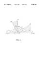
- FIG. 3shows a top view of the inside mechanism assembly of the rehabilitation apparatus of the present invention
- FIG. 4shows a front view of the inside mechanism assembly of the rehabilitation apparatus of the present invention
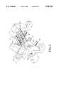
- FIG. 5shows the transversely translating/sliding mechanism of the rehabilitation apparatus of the present invention, which makes use of the transverse screw to drive the transverse slider and, in turn, the longitudinal slider rails to rotate;
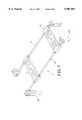
- FIG. 6shows a view of the thigh supporting/moving mechanism of the rehabilitation apparatus of the present invention which supports the thigh;
- FIG. 7shows a view of the sole supporting/moving mechanism of the rehabilitation apparatus of the present invention which supports the sole;
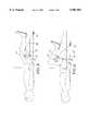
- FIG. 8shows the position of the thigh slider of the rehabilitation apparatus of the present invention when the leg extends
- FIG. 9shows the position of the thigh slider of the rehabilitation apparatus of the present invention when the leg bends.
- FIG. 10shows the relative positions of the thigh, shank and sole when the hip joint is rotated upward.
- FIGS. 1 and 2respectively show the definition of the angular range of rotation of the patient's hip joint and the inward retraction and outward expansion of the patient's thigh.
- the present inventionis a rehabilitation apparatus which comprises a transversely movable slider mechanism 2, a thigh supporting/moving mechanism 3 and a sole supporting/moving mechanism 4, all theses mechanisms being mounted to a base frame 1.
- a coordinate systemis defined on the base frame 1 in which the Y-axis is in a longitudinal direction and the X-axis in a transverse direction.
- the Z-axisis defined as a direction normal to the plane defined by the X-axis and the Y-axis.
- the thigh supporting/moving mechanism 3comprises: a first elongated bar 31, a second elongated bar 32, a thigh slider 33, a thigh support 34 and a longitudinal slider 35.
- a motor 52is actuated, a longitudinal screw rod 27, which is coupled to the motor 52 by means of a flexible coupling 53, is driven to rotate and the longitudinal slider 35 moves in the Y direction along two parallel longitudinal slide rails 26 and along the longitudinal screw rod 27.
- the longitudinal slider 35together with the first elongated bar 31 and the second elongated bar 32, forms a basic crank-slider mechanism.
- the first elongated bar 31changes the angle thereof due to the displacement of the longitudinal slider 35.
- the thigh slider 33 that supports the thighcomprises a sliding mechanism that allows the thigh slider 33 to freely move along the first elongated bar 31.
- the sliding mechanism of the thigh slider 33is shown in detail in FIG. 6.
- the transversely movable slider mechanism 2comprises: a pair of parallel transverse slide rails 21, a transverse screw rod 22, a transverse slider 23, a spherical joint 24, a spherical joint socket 25, a pair of parallel longitudinal slide rails 26, a longitudinal screw rod 27, a pair of transverse slide rail supports 28, wherein the transverse screw rod 22 is coupled to a motor 51 which, when rotating, drives the transverse screw rod 22 to rotate and thus makes the transverse slider 23 to translate in the X direction along the transverse slide rails 21 and the transverse screw rod 22.
- the spherical joint 24is fixed on the transverse slider 23 and coupled to the spherical joint socket 25 which is rotatable around the central axis of the longitudinal screw rod 27.
- FIGS. 3 and 4show the details of how these elements connect with each other. Further referring to FIGS. 3 and 4, when the transverse slider 23 translates, the spherical joint 24 drives the spherical joint socket 25 to rotate, thus causing the longitudinal slide rails 26 connected thereto to rotate. When the longitudinal slide rails rotate, the longitudinal slider 35 mounted thereon rotates therewith and drives the first and second elongated bars 31 and 32 to rotate.
- a sole supporting/moving mechanism 4is particularly provided to accommodate the variance in the length of patients' shank in the present invention.
- a sole support 45which is provided to hold and support the sole is mounted on two particularly-designed, inclined slide rails 41 which are parallel to each other, as shown in FIG. 7, wherein the inclined sliding rails 41 have an inclination of 12°to 18°,preferably about 15°. The inclination serves to prevent injury to the ankle caused by excessive force acting upon the sole when the hip joint is rotated upward. Referring to FIGS.
- an included angle between the shank and the soleis A1 which is substantially equal to 90° at this position.
- the included angle A3would be greater than A2 as shown in the drawings if the slide rails are designed to be inclined as described above. The smaller the included angle, the greater the pressure acting upon the sole and the risk of the patient's being injured and the patient's feeling pain will increase. Thus, a suitable inclination is necessary for the design of the slide rails.
- the included angle A3would substantially be equal to 85°.
- the soleis subject to the action of a small angle (5°-15°) which provides a small amount of passive exercise to the ankle joint. This helps alleviate the stiffness of the ankle joint.
- the feature of the sole supporting/moving mechanism 4is to accommodate variance in the lengths of shanks in order to protect the ankle joint from being hurt and also offers a small angle of reciprocative motion to the ankle joint.
- the patientis first laid down on the apparatus and the thigh to be rehabilitated is placed on the thigh support 34 of the thigh slider 33 and the sole on the sole support 45 and tightly fastened thereon.
- the rehabilitation apparatusis first operated at a low speed. Once it is inspected and found to have no problems, then the rehabilitation apparatus is switched to a normal speed.
- the thigh slider 33 that supports the thighcomprises a sliding mechanism as shown in FIGS. 8, 9 and 4.
- the hip jointis rotated, it is observed that the thigh slider 33 is also upwardly movable with respect to the first elongated bar 31. This not only releases the force that has been applied to the thigh, but also provides an adjustment device which provides a proper adjustment on the basis of the patient's thigh length.
- a major feature of the present inventionis that besides turning on the motor 52 to perform bending motion of the lower limb of the patient, turning on the other motor 51 would cause the thigh supporting/moving mechanism 3 to rotate in a small range so as to cause the hip joint of the patient to rotate an inward retraction and outward expansion motion of the thigh shown in FIG. 2.
- the rehabilitation apparatus of the present inventionallows the hip joint of the patient to move within a maximum rotation angle of 90°-100° and an inward retraction and outward expansion angle of up to 30°-35° which is suitable for patients of different heights and allows for three different motions of the human body, including hip rotation, thigh inward retraction/outward expansion and small angle ankle pressing motion. No second injury will likely occur to the patient.
- the rehabilitation apparatus of the present inventioncomprises a novel and unique design of a mechanism which has been tested a number of times and for which excellent results have been obtained.
- the apparatus of the present inventionhas value in the area of medical rehabilitation.
Landscapes
- Health & Medical Sciences (AREA)
- Epidemiology (AREA)
- Pain & Pain Management (AREA)
- Physical Education & Sports Medicine (AREA)
- Rehabilitation Therapy (AREA)
- Life Sciences & Earth Sciences (AREA)
- Animal Behavior & Ethology (AREA)
- General Health & Medical Sciences (AREA)
- Public Health (AREA)
- Veterinary Medicine (AREA)
- Rehabilitation Tools (AREA)
Abstract
Description
Acute cerebral vascular impairment (usually referred to as a cerebral vascular accident) and vertebra impairment usually cause lower limb paralysis. The paralysis of a lower limb usually leads to joint stiffness and muscle atrophy at the hip joint, knee joint and ankle joint due to the lack of passive joint motion, which may even cause bed sores if the patient has been lying down in bed for a very long time. Thus, it is desirable to provide proper physical rehabilitation before the situation becomes worse.
However, due to the lack of rehabilitation personnel, most patients are not given sufficient rehabilitation treatment. As a consequence their lower limbs may be disabled and the patient may no longer be able to adapt himself or herself to his/her family and social life. This will give the patient's family and society in general heavy burden.
The current mechanical rehabilitation device performs only simple bending and extension/retraction exercises for the lower limb. It is not able to facilitate rotation motion for the hip joint, the knee joint and the ankle joint. Thus, as the muscle and joint of the patient's lower limb may not be fully exercised, and the function may be getting worse, the effectiveness of the conventional rehabilitation devices is very limited. Thus, the conventional rehabilitation device can not replace manual rehabilitation effectively.
Due to the above reasons, it is desirable to have a rehabilitation apparatus that possesses full rehabilitation function in order to replace manual rehabilitation. By using mechanical means to replace manual rehabilitation in performing periodic and regular exercise on the above-mentioned joints will reduce the occurrence of bed sores and muscle atrophy and will thus be of great help to the patient and his or her family.
The present invention is related to a rehabilitation apparatus which provides multiple degrees of freedom of motion to assist the paralytic lower limb of a patient having cerebral vascular impairment or vertebra impairment to perform exercise of more degrees of freedom so as to facilitate the rehabilitation of said lower limb. This invention at best, helps the recovery of the limb and, at worst, prevents the condition of the limb from getting worse.
The rehabilitation apparatus of the present invention utilizes electricity as a power source to drive the sliding mechanism for performing mechanical displacement to generate a three dimensional motion, the range and speed of which are adjustable, and which helps the hip joint, knee joint and ankle joint of the patient perform passive exercise in the upward and downward directions and the inward and outward directions at proper periods and with proper loads.
The rehabilitation apparatus of the present invention comprises: a transversely movable slider mechanism, a thigh supporting/moving mechanism and a sole supporting/moving mechanism; wherein the transversely movable slider mechanism makes use of a transversely movable slider which incorporates a spherical joint so that it generates a rotational motion to provide clockwise and counterclockwise rotation of the patient's limb; the thigh supporting/moving mechanism supports the thigh and makes use of a thigh slider to allow the retraction and expansion of the lower limb to be performed smoothly so as to avoid injury to the patient; the sole supporting/moving mechanism provides the sole with free movement when the limb is being bent and released so as to avoid undue pressure on the sole, the sliding mechanism being capable of being set at a particular angle with respect to the horizontal plane so as to have the inward bending of the sole within a suitable range of angles.
In summary, what the present invention may achieve may be categorized into three benefits:
(1) increasing the range of motion for the hip joint, knee joint and ankle joint of the paralytic lower limb so as to improve the functionability of the patient's limb;
(2) enhancing the blood circulation of the paralytic limb and the motion in the joints in order to reduce the occurrence of bed sores; and
(3) allowing rehabilitation to be conducted without the manual assistance of other persons so as to help recovery of the function of the patient is limb.
FIG. 1 shows the definition of the hip joint rotation angle adapted in the present invention;
FIG. 2 shows the definition of the thigh inward retraction and outward expansion in the present invention;
FIG. 3 shows a top view of the inside mechanism assembly of the rehabilitation apparatus of the present invention;
FIG. 4 shows a front view of the inside mechanism assembly of the rehabilitation apparatus of the present invention;
FIG. 5 shows the transversely translating/sliding mechanism of the rehabilitation apparatus of the present invention, which makes use of the transverse screw to drive the transverse slider and, in turn, the longitudinal slider rails to rotate;
FIG. 6 shows a view of the thigh supporting/moving mechanism of the rehabilitation apparatus of the present invention which supports the thigh;
FIG. 7 shows a view of the sole supporting/moving mechanism of the rehabilitation apparatus of the present invention which supports the sole;
FIG. 8 shows the position of the thigh slider of the rehabilitation apparatus of the present invention when the leg extends;
FIG. 9 shows the position of the thigh slider of the rehabilitation apparatus of the present invention when the leg bends; and
FIG. 10 shows the relative positions of the thigh, shank and sole when the hip joint is rotated upward.
A preferred embodiment of the present invention will be described in detail as follows with reference to the attached drawings.
FIGS. 1 and 2 respectively show the definition of the angular range of rotation of the patient's hip joint and the inward retraction and outward expansion of the patient's thigh. The present invention, as shown in FIGS. 3 and 4, is a rehabilitation apparatus which comprises a transversely movable slider mechanism 2, a thigh supporting/moving mechanism 3 and a sole supporting/moving mechanism 4, all theses mechanisms being mounted to abase frame 1. A coordinate system is defined on thebase frame 1 in which the Y-axis is in a longitudinal direction and the X-axis in a transverse direction. The Z-axis is defined as a direction normal to the plane defined by the X-axis and the Y-axis.
In the main structure of the rehabilitation apparatus in accordance with the present invention, the thigh supporting/moving mechanism 3 comprises: a firstelongated bar 31, a secondelongated bar 32, athigh slider 33, athigh support 34 and alongitudinal slider 35. When amotor 52 is actuated, alongitudinal screw rod 27, which is coupled to themotor 52 by means of aflexible coupling 53, is driven to rotate and thelongitudinal slider 35 moves in the Y direction along two parallellongitudinal slide rails 26 and along thelongitudinal screw rod 27. Thelongitudinal slider 35, together with the firstelongated bar 31 and the secondelongated bar 32, forms a basic crank-slider mechanism. The firstelongated bar 31 changes the angle thereof due to the displacement of thelongitudinal slider 35. By means of alternately rotating thescrew rod 27 in the forward direction and the reverse direction, a reciprocal motion is induced on theslider 35 which causes the firstelongated bar 31 to alternately rotate in forward and reverse direction. In addition, thethigh slider 33 that supports the thigh comprises a sliding mechanism that allows thethigh slider 33 to freely move along the firstelongated bar 31. The sliding mechanism of thethigh slider 33 is shown in detail in FIG. 6.
The transversely movable slider mechanism 2 comprises: a pair of paralleltransverse slide rails 21, atransverse screw rod 22, atransverse slider 23, aspherical joint 24, aspherical joint socket 25, a pair of parallellongitudinal slide rails 26, alongitudinal screw rod 27, a pair of transverse slide rail supports 28, wherein thetransverse screw rod 22 is coupled to amotor 51 which, when rotating, drives thetransverse screw rod 22 to rotate and thus makes thetransverse slider 23 to translate in the X direction along thetransverse slide rails 21 and thetransverse screw rod 22. Thespherical joint 24 is fixed on thetransverse slider 23 and coupled to thespherical joint socket 25 which is rotatable around the central axis of thelongitudinal screw rod 27. FIG. 5 shows the details of how these elements connect with each other. Further referring to FIGS. 3 and 4, when thetransverse slider 23 translates, thespherical joint 24 drives thespherical joint socket 25 to rotate, thus causing thelongitudinal slide rails 26 connected thereto to rotate. When the longitudinal slide rails rotate, thelongitudinal slider 35 mounted thereon rotates therewith and drives the first and secondelongated bars
Since the length of the leg shank may vary from person to person, a sole supporting/movingmechanism 4 is particularly provided to accommodate the variance in the length of patients' shank in the present invention. Asole support 45 which is provided to hold and support the sole is mounted on two particularly-designed,inclined slide rails 41 which are parallel to each other, as shown in FIG. 7, wherein the inclinedsliding rails 41 have an inclination of 12°to 18°,preferably about 15°. The inclination serves to prevent injury to the ankle caused by excessive force acting upon the sole when the hip joint is rotated upward. Referring to FIGS. 4 and 10, when the thigh, the shank and the sole are placed in the initial starting position (namely, before the thigh is rotated), an included angle between the shank and the sole is A1 which is substantially equal to 90° at this position. When the hip joint begins to rotate upward the included angle between the shank and the sole is A2, if horizontal sliding rails are used to guide thesole support 45. On the other hand, the included angle A3 would be greater than A2 as shown in the drawings if the slide rails are designed to be inclined as described above. The smaller the included angle, the greater the pressure acting upon the sole and the risk of the patient's being injured and the patient's feeling pain will increase. Thus, a suitable inclination is necessary for the design of the slide rails. Furthermore, if the inclination is 15°, then when the hip joint is rotated 90°, the included angle A3 would substantially be equal to 85°. Namely, the sole is subject to the action of a small angle (5°-15°) which provides a small amount of passive exercise to the ankle joint. This helps alleviate the stiffness of the ankle joint. In other words, the feature of the sole supporting/movingmechanism 4 is to accommodate variance in the lengths of shanks in order to protect the ankle joint from being hurt and also offers a small angle of reciprocative motion to the ankle joint.
As shown in FIG. 4, while using the rehabilitation apparatus of the present invention, the patient is first laid down on the apparatus and the thigh to be rehabilitated is placed on thethigh support 34 of thethigh slider 33 and the sole on thesole support 45 and tightly fastened thereon. The rehabilitation apparatus is first operated at a low speed. Once it is inspected and found to have no problems, then the rehabilitation apparatus is switched to a normal speed.
When the hip joint is rotated up and down and swung outward/inward, the above described motion induces an upward and/or downward force on the thigh and may cause pain to the patient and may even lead to a second injury. To avoid such a problem, thethigh slider 33 that supports the thigh comprises a sliding mechanism as shown in FIGS. 8, 9 and 4. When the hip joint is rotated, it is observed that thethigh slider 33 is also upwardly movable with respect to the firstelongated bar 31. This not only releases the force that has been applied to the thigh, but also provides an adjustment device which provides a proper adjustment on the basis of the patient's thigh length.
A major feature of the present invention is that besides turning on themotor 52 to perform bending motion of the lower limb of the patient, turning on theother motor 51 would cause the thigh supporting/moving mechanism 3 to rotate in a small range so as to cause the hip joint of the patient to rotate an inward retraction and outward expansion motion of the thigh shown in FIG. 2. A practical test reveals that the rehabilitation apparatus of the present invention allows the hip joint of the patient to move within a maximum rotation angle of 90°-100° and an inward retraction and outward expansion angle of up to 30°-35° which is suitable for patients of different heights and allows for three different motions of the human body, including hip rotation, thigh inward retraction/outward expansion and small angle ankle pressing motion. No second injury will likely occur to the patient.
In conclusion, the rehabilitation apparatus of the present invention comprises a novel and unique design of a mechanism which has been tested a number of times and for which excellent results have been obtained. Clearly, the apparatus of the present invention has value in the area of medical rehabilitation.
After having been described in detail and illustrated with respect to the preferred embodiment, the structure and feature of the present invention will become apparent. However, it should be noted that the preferred embodiment provides and demonstrates only the best mode for carrying out the present invention. This is not intended to limit the scope of the present invention and any other modification and variation that are made without departing from the spirit of the present invention is considered within the scope to be protected of the invention.
Claims (7)
1. A paralytic lower limb rehabilitation apparatus comprising:
a base frame having a longitudinal axis Y, the base frame being firmly placed on a flat surface;
a transversely movable slider mechanism, which comprises a transverse screw rod, a pair of transverse slide rails, a transverse slider, a spherical joint, a spherical joint socket, a pair of longitudinal slide rails and a longitudinal screw rod, wherein the pair of transverse slide rails are perpendicular to the longitudinal axis Y and fixed to the base frame at a position in the proximity of a front end of the base frame, the transverse screw rod being located between the pair of transverse slide rails, the transverse slider being driveable by the transverse screw rod to slide along the pair of transverse slide rails, the transverse slider having the spherical joint mounted on a front end thereof to engage the spherical joint socket to allow the spherical joint to rotate with respect to the spherical joint socket and to slide up and down, the spherical joint socket being connected to one end of the pair of longitudinal slide rails, the longitudinal slide rails having a second end fixed to the base frame, the long screw rod is mounted between the slide rails;
a thigh supporting/moving mechanism arranged on a forepart of the base frame, comprising a first and a second elongated bars, and a longitudinal slider, wherein the first elongated bar has an end pivotally connected to the base frame and a second end pivotally connected to one end of the second elongated bar, the second elongated bar having a second end pivotally connected to the longitudinal slider which is movable along the longitudinal slide rails;
a sole supporting/moving mechanism arranged on a rear half of the base frame, comprising a pair of slide rails and a sole slider, the slide rails having their front and rear ends fixed to the base frame, the sole slider being freely and slidably reciprocated along the slide rails.
2. The paralytic lower limb rehabilitation apparatus as claimed in claim 1, wherein the transverse screw rod and the longitudinal screw rod of the transverse movable slider mechanism are driven to rotate by motors.
3. The paralytic lower limb rehabilitation apparatus as claimed in claim 1, wherein the transverse slider is movable along a distance to have the spherical joint socket rotate 35° in both the clockwise and counter-clockwise direction.
4. The paralytic lower limb rehabilitation apparatus as claimed in claim 1, wherein the slide rails of the sole supporting/moving mechanism with respect to the horizontal plane have an inclination angle range of between 12°-18°.
5. The paralytic lower limb rehabilitation apparatus as claimed in claim 1, wherein the thigh supporting/moving mechanism further comprises a thigh support that supports the thigh and is free to slide along the first elongated bar.
6. The paralytic lower limb rehabilitation apparatus as claimed in claim 2, wherein the longitudinal screw rod is connected to the motor by means of a flexible coupling.
7. The paralytic lower limb rehabilitation apparatus as claimed in claim 4, wherein the inclination angle is configured so that the resulted inward bending of the sole is within the range of 5°-15°.
Applications Claiming Priority (2)
| Application Number | Priority Date | Filing Date | Title |
|---|---|---|---|
| TW086209397UTW321903U (en) | 1997-06-07 | 1997-06-07 | Rehabilitation machine for lower limbs disabled person |
| CN86209397 | 1997-06-07 |
Publications (1)
| Publication Number | Publication Date |
|---|---|
| US5901581Atrue US5901581A (en) | 1999-05-11 |
Family
ID=21628088
Family Applications (1)
| Application Number | Title | Priority Date | Filing Date |
|---|---|---|---|
| US09/092,541Expired - Fee RelatedUS5901581A (en) | 1997-06-07 | 1998-06-05 | Paralytic lower limb rehabilitation apparatus |
Country Status (3)
| Country | Link |
|---|---|
| US (1) | US5901581A (en) |
| JP (2) | JPH1170148A (en) |
| TW (1) | TW321903U (en) |
Cited By (32)
| Publication number | Priority date | Publication date | Assignee | Title |
|---|---|---|---|---|
| US6318134B1 (en) | 1998-07-14 | 2001-11-20 | Mossberg Safe Systems, Inc. | Safe locking mechanism |
| US6443916B1 (en)* | 2000-01-10 | 2002-09-03 | B. To B. Ltd. | Device for preventing or relieving pain in the lower back |
| US20030200971A1 (en)* | 2002-04-29 | 2003-10-30 | P.P.T.T. L.L.P. | Patient support for external counterpulsation cardiac assist device |
| US6685658B1 (en)* | 1999-04-07 | 2004-02-03 | Balgrist/Schweiz. Paraplegikerzentrum | Device and method for a locomotion therapy |
| US20060064044A1 (en)* | 2004-09-17 | 2006-03-23 | Ana-Tek, Llc | Apparatus and method for supporting and continuously flexing a jointed limb |
| WO2006094018A1 (en)* | 2005-03-01 | 2006-09-08 | Rle Corporation | Paraplegic rehabilitation apparatus |
| US20070161479A1 (en)* | 2006-01-10 | 2007-07-12 | Harris Donald T | Knee-stretching Device and Treatment Methods |
| US20070287936A1 (en)* | 2004-10-12 | 2007-12-13 | Taisuke Matsushita | Continuous Passive Motion Device |
| US20080288107A1 (en)* | 2007-05-14 | 2008-11-20 | Oki Electric Industry Co., Ltd. | Robot for training a rehabilitator |
| WO2009125347A2 (en) | 2008-04-09 | 2009-10-15 | Scuola Superiore Di Studi Universitari E Di Perfezionamento Sant'anna | Robotic device for lower limb functionality recovery in bed-bound post-stroke patients |
| US20090258767A1 (en)* | 2008-04-11 | 2009-10-15 | Andre Foucault | Leg rehabilitation apparatus |
| WO2009135619A1 (en) | 2008-05-05 | 2009-11-12 | Medireha GmbH Produkte für die medizinische Rehabilitation | Leg movement rail for the repetitive movement of the knee and hip joint with assistance function for active use |
| US20110112455A1 (en)* | 2009-11-12 | 2011-05-12 | Tony Rocklin | Hip traction device and methods |
| US20120006335A1 (en)* | 2010-07-07 | 2012-01-12 | University Of Virginia Patent Foundation | Hip Continuous Passive Motion Device and Related Methods |
| WO2014028363A1 (en)* | 2012-08-12 | 2014-02-20 | Method Therapeutic Solutions, Llc | Orthopedic stretcher |
| US20140094721A1 (en)* | 2012-09-28 | 2014-04-03 | Ibrahima Diallo | Device and Method for Knee Rehabilitation |
| US20140100093A1 (en)* | 2011-05-30 | 2014-04-10 | Seung Hoon Oh | Total-body exerciser |
| USD716459S1 (en) | 2013-03-11 | 2014-10-28 | Raz Liran | Device for treating back pain |
| CN104644377A (en)* | 2015-01-22 | 2015-05-27 | 哈尔滨工程大学 | Sitting and lying type lower limb rehabilitation device |
| US9510989B2 (en) | 2010-03-22 | 2016-12-06 | Kinex Connect, Llc | Orthopedic stretcher |
| US9566470B2 (en)* | 2015-03-16 | 2017-02-14 | Mary Ann Malizia | Leg stretcher |
| WO2017120680A1 (en) | 2016-01-17 | 2017-07-20 | Siamak Arzanpour | System and device for guiding and detecting motions of 3-dof rotational target joint |
| US9814648B2 (en) | 2009-11-12 | 2017-11-14 | Tony Rocklin | Hip traction device, system, and methods |
| CN108652932A (en)* | 2018-06-07 | 2018-10-16 | 南通市第二人民医院 | A kind of hemiplegic patient care device |
| US10307320B2 (en) | 2013-03-11 | 2019-06-04 | Backlife Ltd. | Device for relieving or preventing lower back pain |
| US10420691B2 (en) | 2016-02-24 | 2019-09-24 | Richard Stewart | Knee range of motion device utilizing tangential joint translation and distraction |
| CN110575353A (en)* | 2019-09-25 | 2019-12-17 | 深圳市丞辉威世智能科技有限公司 | Exoskeleton for limb rehabilitation |
| US10576008B2 (en) | 2014-11-11 | 2020-03-03 | Ekso Bionics, Inc. | Methods of enhancing the rehabilitation or training of an exoskeleton wearer |
| US11011262B2 (en) | 2015-10-07 | 2021-05-18 | Kinex Medical Company, Llc | Retrofitted continuous passive motion devices |
| CN113499221A (en)* | 2021-07-14 | 2021-10-15 | 合肥技加医疗科技有限公司 | Lower limb multidimensional rehabilitation training device |
| US11369821B2 (en)* | 2015-12-31 | 2022-06-28 | Ajou University Industry-Academic Cooperation Foundation | Passive and active driving device for strengthening muscle |
| CN114699720A (en)* | 2022-03-14 | 2022-07-05 | 北京诺亦腾科技有限公司 | Lower limb rehabilitation training device |
Families Citing this family (11)
| Publication number | Priority date | Publication date | Assignee | Title |
|---|---|---|---|---|
| JP2006239086A (en)* | 2005-03-02 | 2006-09-14 | Matsushita Electric Works Ltd | Walking sensation generating device |
| KR100799098B1 (en) | 2007-01-19 | 2008-01-29 | 연세대학교 산학협력단 | Rehabilitation equipment |
| KR100936621B1 (en)* | 2008-03-20 | 2010-01-13 | 경희대학교 산학협력단 | Leg exercise rehabilitation apparatus |
| JP5598756B2 (en)* | 2010-07-29 | 2014-10-01 | 国立大学法人九州工業大学 | Thrombosis prevention device |
| CN102764172A (en)* | 2011-05-06 | 2012-11-07 | 翁仁政 | Rehabilitation Equipment and Rehabilitation System |
| CN102579229B (en)* | 2012-03-02 | 2013-11-27 | 王俊华 | Gait rehabilitation training robot |
| CN108553268A (en)* | 2018-05-09 | 2018-09-21 | 合肥工业大学 | It is a kind of equal than adjustable lower limb healing robot |
| CN108771591A (en)* | 2018-06-29 | 2018-11-09 | 无锡市惠山区人民医院 | A kind of multifunctional lower limb appurtenance |
| CN110200782B (en)* | 2019-05-30 | 2024-08-30 | 上海长征医院 | Lower limb function exercise device |
| TWI798669B (en)* | 2021-03-29 | 2023-04-11 | 亞東學校財團法人亞東科技大學 | Knee rehabilitation device |
| TWI880703B (en)* | 2024-04-02 | 2025-04-11 | 長庚學校財團法人長庚科技大學 | Leg rehabilitation device |
Citations (6)
| Publication number | Priority date | Publication date | Assignee | Title |
|---|---|---|---|---|
| DE2015054A1 (en)* | 1970-03-28 | 1971-10-14 | Bimler, Rudolf, Dr med , 2190 Cuxhaven | Movement rail for legs |
| SU640740A1 (en)* | 1977-07-12 | 1979-01-05 | Предприятие П/Я В-2769 | Arrangement for developing mobility of the joint of lower extremities |
| US4549534A (en)* | 1983-01-13 | 1985-10-29 | Zagorski Joseph B | Leg exercise device |
| EP0190086A1 (en)* | 1985-01-17 | 1986-08-06 | COMPAGNIE GENERALE DE MATERIEL ORTHOPEDIQUE Société Anonyme: | Apparatus for the mobilization of a lower limb |
| US4834073A (en)* | 1987-02-20 | 1989-05-30 | Medical Technology, Inc. | Passive motion exerciser |
| EP0535513A1 (en)* | 1991-10-02 | 1993-04-07 | Ernst Knoll Feinmechanik | Guide means for the treatment of the lower limbs |
- 1997
- 1997-06-07TWTW086209397Upatent/TW321903U/enunknown
- 1998
- 1998-06-05JPJP10193535Apatent/JPH1170148A/enactivePending
- 1998-06-05USUS09/092,541patent/US5901581A/ennot_activeExpired - Fee Related
- 1999
- 1999-04-21JPJP1999002707Upatent/JP3063280U/ennot_activeExpired - Lifetime
Patent Citations (6)
| Publication number | Priority date | Publication date | Assignee | Title |
|---|---|---|---|---|
| DE2015054A1 (en)* | 1970-03-28 | 1971-10-14 | Bimler, Rudolf, Dr med , 2190 Cuxhaven | Movement rail for legs |
| SU640740A1 (en)* | 1977-07-12 | 1979-01-05 | Предприятие П/Я В-2769 | Arrangement for developing mobility of the joint of lower extremities |
| US4549534A (en)* | 1983-01-13 | 1985-10-29 | Zagorski Joseph B | Leg exercise device |
| EP0190086A1 (en)* | 1985-01-17 | 1986-08-06 | COMPAGNIE GENERALE DE MATERIEL ORTHOPEDIQUE Société Anonyme: | Apparatus for the mobilization of a lower limb |
| US4834073A (en)* | 1987-02-20 | 1989-05-30 | Medical Technology, Inc. | Passive motion exerciser |
| EP0535513A1 (en)* | 1991-10-02 | 1993-04-07 | Ernst Knoll Feinmechanik | Guide means for the treatment of the lower limbs |
Cited By (50)
| Publication number | Priority date | Publication date | Assignee | Title |
|---|---|---|---|---|
| US6318134B1 (en) | 1998-07-14 | 2001-11-20 | Mossberg Safe Systems, Inc. | Safe locking mechanism |
| US6685658B1 (en)* | 1999-04-07 | 2004-02-03 | Balgrist/Schweiz. Paraplegikerzentrum | Device and method for a locomotion therapy |
| US6443916B1 (en)* | 2000-01-10 | 2002-09-03 | B. To B. Ltd. | Device for preventing or relieving pain in the lower back |
| AU785164B2 (en)* | 2000-01-10 | 2006-10-05 | Backlife Ltd. | Device for preventing or relieving pain in the lower back |
| US7179237B2 (en) | 2000-01-10 | 2007-02-20 | Backlife Ltd. | Device for preventing or relieving pain in the lower back |
| US20030200971A1 (en)* | 2002-04-29 | 2003-10-30 | P.P.T.T. L.L.P. | Patient support for external counterpulsation cardiac assist device |
| US6948501B2 (en)* | 2002-04-29 | 2005-09-27 | P.P.T.T. L.L.P. | Patient support for external counterpulsation cardiac assist device |
| US20060064044A1 (en)* | 2004-09-17 | 2006-03-23 | Ana-Tek, Llc | Apparatus and method for supporting and continuously flexing a jointed limb |
| US7309320B2 (en) | 2004-09-17 | 2007-12-18 | Ana-Tek, Llc | Apparatus and method for supporting and continuously flexing a jointed limb |
| US20070287936A1 (en)* | 2004-10-12 | 2007-12-13 | Taisuke Matsushita | Continuous Passive Motion Device |
| WO2006094018A1 (en)* | 2005-03-01 | 2006-09-08 | Rle Corporation | Paraplegic rehabilitation apparatus |
| US20070161479A1 (en)* | 2006-01-10 | 2007-07-12 | Harris Donald T | Knee-stretching Device and Treatment Methods |
| US8311671B2 (en)* | 2007-05-14 | 2012-11-13 | Oki Electric Industry Co., Ltd. | Robot for training a rehabilitator |
| US20080288107A1 (en)* | 2007-05-14 | 2008-11-20 | Oki Electric Industry Co., Ltd. | Robot for training a rehabilitator |
| WO2009125347A2 (en) | 2008-04-09 | 2009-10-15 | Scuola Superiore Di Studi Universitari E Di Perfezionamento Sant'anna | Robotic device for lower limb functionality recovery in bed-bound post-stroke patients |
| US20090258767A1 (en)* | 2008-04-11 | 2009-10-15 | Andre Foucault | Leg rehabilitation apparatus |
| US7874968B2 (en)* | 2008-04-11 | 2011-01-25 | Andre Foucault | Leg rehabilitation apparatus |
| WO2009135619A1 (en) | 2008-05-05 | 2009-11-12 | Medireha GmbH Produkte für die medizinische Rehabilitation | Leg movement rail for the repetitive movement of the knee and hip joint with assistance function for active use |
| US20110040215A1 (en)* | 2008-05-05 | 2011-02-17 | Medireha GmbH Produkte fur die medizinische Rehabilitation | Leg movement rail for the repetitive movement of the knee and hip joint with assistance function for active use |
| US9801773B2 (en) | 2009-11-12 | 2017-10-31 | Tony Rocklin | Hip traction device and methods |
| WO2011059687A3 (en)* | 2009-11-12 | 2011-10-06 | Tony Rocklin | Hip traction device and methods |
| US20110112455A1 (en)* | 2009-11-12 | 2011-05-12 | Tony Rocklin | Hip traction device and methods |
| US11590043B2 (en) | 2009-11-12 | 2023-02-28 | Tony Rocklin | Hip traction device, system, and methods |
| US9814648B2 (en) | 2009-11-12 | 2017-11-14 | Tony Rocklin | Hip traction device, system, and methods |
| US9510989B2 (en) | 2010-03-22 | 2016-12-06 | Kinex Connect, Llc | Orthopedic stretcher |
| US20120006335A1 (en)* | 2010-07-07 | 2012-01-12 | University Of Virginia Patent Foundation | Hip Continuous Passive Motion Device and Related Methods |
| US10159619B2 (en)* | 2010-07-07 | 2018-12-25 | University Of Virginia Patent Foundation | Hip continuous passive motion device and related methods |
| US20140100093A1 (en)* | 2011-05-30 | 2014-04-10 | Seung Hoon Oh | Total-body exerciser |
| US9314669B2 (en)* | 2011-05-30 | 2016-04-19 | Overtech Co., Ltd. | Total-body exerciser |
| WO2014028363A1 (en)* | 2012-08-12 | 2014-02-20 | Method Therapeutic Solutions, Llc | Orthopedic stretcher |
| US20140094721A1 (en)* | 2012-09-28 | 2014-04-03 | Ibrahima Diallo | Device and Method for Knee Rehabilitation |
| USD716459S1 (en) | 2013-03-11 | 2014-10-28 | Raz Liran | Device for treating back pain |
| US10307320B2 (en) | 2013-03-11 | 2019-06-04 | Backlife Ltd. | Device for relieving or preventing lower back pain |
| US10576008B2 (en) | 2014-11-11 | 2020-03-03 | Ekso Bionics, Inc. | Methods of enhancing the rehabilitation or training of an exoskeleton wearer |
| CN104644377B (en)* | 2015-01-22 | 2016-09-14 | 哈尔滨工程大学 | A sitting and lying lower limb rehabilitation device |
| CN104644377A (en)* | 2015-01-22 | 2015-05-27 | 哈尔滨工程大学 | Sitting and lying type lower limb rehabilitation device |
| US9566470B2 (en)* | 2015-03-16 | 2017-02-14 | Mary Ann Malizia | Leg stretcher |
| US11011262B2 (en) | 2015-10-07 | 2021-05-18 | Kinex Medical Company, Llc | Retrofitted continuous passive motion devices |
| US11369821B2 (en)* | 2015-12-31 | 2022-06-28 | Ajou University Industry-Academic Cooperation Foundation | Passive and active driving device for strengthening muscle |
| CN108472145B (en)* | 2016-01-17 | 2021-07-02 | 人类运动机器人技术公司 | System and apparatus for guiding and detecting motion of a 3-DOF rotational target joint |
| EP3402444A4 (en)* | 2016-01-17 | 2019-10-16 | Human in Motion Robotics Inc. | SYSTEM AND DEVICE FOR GUIDING AND DETECTING ROTATION MOVEMENTS AT 3 DEGREES OF FREEDOM OF A TARGET JOINT |
| WO2017120680A1 (en) | 2016-01-17 | 2017-07-20 | Siamak Arzanpour | System and device for guiding and detecting motions of 3-dof rotational target joint |
| US11135120B2 (en) | 2016-01-17 | 2021-10-05 | Human In Motion Robotics Inc. | System and device for guiding and detecting motions of 3-DOF rotational target joint |
| CN108472145A (en)* | 2016-01-17 | 2018-08-31 | 人类运动机器人技术公司 | System and equipment for the movement for guiding and detecting 3-DOF rolling targets joint |
| US11612537B2 (en) | 2016-01-17 | 2023-03-28 | Human In Motion Robotics Inc. | System and device for guiding and detecting motions of 3-DOF rotational target joint |
| US10420691B2 (en) | 2016-02-24 | 2019-09-24 | Richard Stewart | Knee range of motion device utilizing tangential joint translation and distraction |
| CN108652932A (en)* | 2018-06-07 | 2018-10-16 | 南通市第二人民医院 | A kind of hemiplegic patient care device |
| CN110575353A (en)* | 2019-09-25 | 2019-12-17 | 深圳市丞辉威世智能科技有限公司 | Exoskeleton for limb rehabilitation |
| CN113499221A (en)* | 2021-07-14 | 2021-10-15 | 合肥技加医疗科技有限公司 | Lower limb multidimensional rehabilitation training device |
| CN114699720A (en)* | 2022-03-14 | 2022-07-05 | 北京诺亦腾科技有限公司 | Lower limb rehabilitation training device |
Also Published As
| Publication number | Publication date |
|---|---|
| JP3063280U (en) | 1999-10-29 |
| JPH1170148A (en) | 1999-03-16 |
| TW321903U (en) | 1997-12-01 |
Similar Documents
| Publication | Publication Date | Title |
|---|---|---|
| US5901581A (en) | Paralytic lower limb rehabilitation apparatus | |
| KR100942968B1 (en) | A movement machine for rehabilitation medical cure | |
| CN110833497B (en) | An orthopedic knee joint postoperative functional exercise device | |
| CN108289781B (en) | Rehabilitation mechanism for bedridden patient | |
| US8142379B2 (en) | Orthopedic arm and shoulder brace | |
| WO2014101524A1 (en) | Lower limbs rehabilitation training robot | |
| CN213098963U (en) | Lower limb active stretching knee and hip joint exercise device | |
| EP3485863B1 (en) | Sacroiliac joint exercise assistance device in lateral decubitus position | |
| KR100621350B1 (en) | Patient bed with working structure for lower leg joint movement | |
| JP3420546B2 (en) | Lower limb exercise device | |
| CN110200779A (en) | A kind of orthopedic rehabilitation treatment assisted care device and its care method | |
| CN109431699A (en) | Healing robot | |
| CN113317965A (en) | Hip and knee bending angle adjusting device and method | |
| CN110882132A (en) | Rehabilitation training device for ankles | |
| JP2005013534A (en) | Knee-ankle-foot orthosis with power assist mechanism | |
| JP2000325413A (en) | Lower limb rehabilitation device | |
| KR20000031157A (en) | Leg rehabilitation apparatus | |
| JP2007111422A (en) | Chair | |
| CN210355851U (en) | An orthopedic lower limb rehabilitation nursing device | |
| US10159619B2 (en) | Hip continuous passive motion device and related methods | |
| SU1747066A1 (en) | Device for exercising lower extremities | |
| JP3086008U (en) | Built-in function activation exercise machine | |
| CN119837687B (en) | A fixation bracket for lower limb fracture rehabilitation | |
| CN215080427U (en) | Multidirectional draw gear of knee joint for orthopedic rehabilitation nursing | |
| KR102605817B1 (en) | Rehabilitation exercise equipment of knee joint |
Legal Events
| Date | Code | Title | Description |
|---|---|---|---|
| AS | Assignment | Owner name:ORIENTAL INSTITUTE OF TECHNOLOGY, TAIWAN Free format text:ASSIGNMENT OF ASSIGNORS INTEREST;ASSIGNORS:CHEN, JIA-WINE;CHANG, ANN-SHING;KUO, YEU-SHUUN;REEL/FRAME:009230/0170 Effective date:19980601 Owner name:CHU, YIU-TONG, TAIWAN Free format text:ASSIGNMENT OF ASSIGNORS INTEREST;ASSIGNORS:CHEN, JIA-WINE;CHANG, ANN-SHING;KUO, YEU-SHUUN;REEL/FRAME:009230/0170 Effective date:19980601 Owner name:FAR EASTERN MEMORIAL HOSPITAL, TAIWAN Free format text:ASSIGNMENT OF ASSIGNORS INTEREST;ASSIGNORS:CHEN, JIA-WINE;CHANG, ANN-SHING;KUO, YEU-SHUUN;REEL/FRAME:009230/0170 Effective date:19980601 | |
| CC | Certificate of correction | ||
| FPAY | Fee payment | Year of fee payment:4 | |
| FPAY | Fee payment | Year of fee payment:8 | |
| REMI | Maintenance fee reminder mailed | ||
| LAPS | Lapse for failure to pay maintenance fees | ||
| STCH | Information on status: patent discontinuation | Free format text:PATENT EXPIRED DUE TO NONPAYMENT OF MAINTENANCE FEES UNDER 37 CFR 1.362 | |
| FP | Lapsed due to failure to pay maintenance fee | Effective date:20110511 |