US5901223A - Wireless telephone with extension having peripheral devices provided thereon - Google Patents
Wireless telephone with extension having peripheral devices provided thereonDownload PDFInfo
- Publication number
- US5901223A US5901223AUS08/825,865US82586597AUS5901223AUS 5901223 AUS5901223 AUS 5901223AUS 82586597 AUS82586597 AUS 82586597AUS 5901223 AUS5901223 AUS 5901223A
- Authority
- US
- United States
- Prior art keywords
- extension
- speaker
- wireless telephone
- microphone
- telephone unit
- Prior art date
- Legal status (The legal status is an assumption and is not a legal conclusion. Google has not performed a legal analysis and makes no representation as to the accuracy of the status listed.)
- Expired - Lifetime
Links
Images


Classifications
- H—ELECTRICITY
- H04—ELECTRIC COMMUNICATION TECHNIQUE
- H04M—TELEPHONIC COMMUNICATION
- H04M1/00—Substation equipment, e.g. for use by subscribers
- H04M1/02—Constructional features of telephone sets
- H04M1/21—Combinations with auxiliary equipment, e.g. with clocks or memoranda pads
- H—ELECTRICITY
- H04—ELECTRIC COMMUNICATION TECHNIQUE
- H04M—TELEPHONIC COMMUNICATION
- H04M1/00—Substation equipment, e.g. for use by subscribers
- H04M1/02—Constructional features of telephone sets
- H04M1/0202—Portable telephone sets, e.g. cordless phones, mobile phones or bar type handsets
- H04M1/0206—Portable telephones comprising a plurality of mechanically joined movable body parts, e.g. hinged housings
- H04M1/0208—Portable telephones comprising a plurality of mechanically joined movable body parts, e.g. hinged housings characterized by the relative motions of the body parts
- H04M1/0214—Foldable telephones, i.e. with body parts pivoting to an open position around an axis parallel to the plane they define in closed position
- H—ELECTRICITY
- H04—ELECTRIC COMMUNICATION TECHNIQUE
- H04M—TELEPHONIC COMMUNICATION
- H04M1/00—Substation equipment, e.g. for use by subscribers
- H04M1/02—Constructional features of telephone sets
- H04M1/0202—Portable telephone sets, e.g. cordless phones, mobile phones or bar type handsets
- H04M1/0206—Portable telephones comprising a plurality of mechanically joined movable body parts, e.g. hinged housings
- H04M1/0208—Portable telephones comprising a plurality of mechanically joined movable body parts, e.g. hinged housings characterized by the relative motions of the body parts
- H04M1/0225—Rotatable telephones, i.e. the body parts pivoting to an open position around an axis perpendicular to the plane they define in closed position
- H—ELECTRICITY
- H04—ELECTRIC COMMUNICATION TECHNIQUE
- H04M—TELEPHONIC COMMUNICATION
- H04M1/00—Substation equipment, e.g. for use by subscribers
- H04M1/02—Constructional features of telephone sets
- H04M1/03—Constructional features of telephone transmitters or receivers, e.g. telephone hand-sets
Definitions
- the present inventionrelates generally to the field of wireless telephony. Specifically, the present invention relates to a compact wireless telephone which incorporates an extension on which a variety of peripheral devices may be provided.
- Wireless communication systemsparticularly cellular telephones and low-tier radio telephones, are convenient because they allow their users to communicate from almost any location in a service area. Wireless phones also save time. For example, the user of a wireless telephone unit need not waste time looking for an available telephone in order to place a call.
- a wireless telephone unitalso allows its user to take advantage of time spent traveling. For example, with a wireless telephone, the user can be transacting business or making appointments while driving, riding or walking.
- the inventionmay encompass a wireless telephone unit having: a main body; an extension attached to the main body; and a peripheral device disposed on the extension.
- the extensionis moveable between a first extended position and a second retracted position.
- the extensionis rotatably attached to a rear portion of the main body and pivots in the plane of the rear portion of the main body between the first and second positions.
- the extensionis hinged on a side of a front portion of the main body and the extension covers at least some of the front portion when in the second retracted position.
- the peripheral devicemay be: a speaker phone having, for example, a speaker, a microphone and a switch for activating the speaker phone; a digital notepad comprising a keyboard and a display connected to the keyboard; a paper notepad; a numeric keypad for dialling a telephone number to be called; or a calculator.
- the present inventionalso encompasses a method of enhancing the functionality of a wireless telephone unit by attaching an extension having a peripheral device disposed thereon to the main body of the wireless telephone unit, where the extension is moveable between a first extended position and a second retracted position.
- the methodfurther comprises rotatably attaching the extension to a rear portion of the main body such that the extension pivots in the plane of the rear portion of the main body between the first and second positions.
- the methodfurther comprises hinging the extension on a side of a front portion of the main body such that the extension covers at least some of the front portion when in the second retracted position.
- the peripheral device disposed on the extensionmay be: a speaker phone having, for example, a speaker, a microphone and a switch for activating the speaker phone; a digital notepad comprising a keyboard and a display connected to the keyboard; a paper notepad; a numeric keypad for dialling a telephone number to be called; or a calculator.
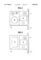
- FIG. 1illustrates a first embodiment of a wireless telephone unit of the present invention with a pivoting extension.
- FIG. 2illustrates the wireless telephone unit of FIG. 1 as viewed from the rear.
- FIG. 3illustrates a second embodiment of a wireless telephone unit of the present invention with a folding extension.
- FIGS. 4 to 8illustrate the wireless telephone unit of FIG. 2 with a variety of different peripherals disposed on the folding extension.
- FIGS. 9 to 13illustrate the wireless telephone unit of FIG. 1 with a variety of different peripherals disposed on the pivoting extension.
- the wireless telephone unit 11 of the present inventionhas a speaker 17, a display 12, e.g., a liquid crystal display, and microphone 13 disposed at the end of arm that is slidable between an extended position and a retracted position as shown in FIG. 1.
- the retractability of microphone 13enhances the compactness and portability of the unit 11.
- Wireless telephone unit 11is also provided with an extension 14 which is attached to the back of the unit 11. As shown in FIG. 2, the extension 14 is attached to the unit 11 by a screw or other fastener 15 that allows the extension 14 to pivot or rotate between a retracted position behind unit 11, and an extended position at the side of unit 11. The pivoting of extension 14 is in the plane of the rear surface of the unit 11. The extended position of extension 14 is pictured in FIGS. 1 and 2.
- the fastener 15may also provide an electrical connection between the extension 14 and the unit 11. This allows electronic peripherals of the wireless telephone unit 11 to be disposed on the extension 14 and to be electrically connected to the unit 11. In this manner, a variety of peripherals to provide additional or supplemental functionalities may be provided on extension 14. Some such peripherals do not require an electric connection to the unit 11, in the which case, fastener 15 need not incorporate such a connection.
- FIG. 3illustrates a second embodiment of the present invention.
- the wireless telephone unit 11 of FIG. 3is provided with much of the same structure as the unit 11 of FIGS. 1 and 2.
- Like featuresare labeled with identical reference numerals and will not be described again.
- the unit 11 of FIG. 3differs from the embodiment of FIGS. 1 and 2 in that the extension provided, extension 16, is connected to the unit 11 by a hinge (not shown) along a side of the front portion of unit 11. This allows the extension 16 to be moved between a closed position in which it covers and closes the unit 11 and an opened position as pictured in FIG. 3.
- extension 16 and unit 11may or may not incorporate an electrical connection.
- the hinge describedwill incorporate an electrical connection if the peripheral provided on extension 16 is electronic and requires an electrical connection to the unit 11.
- FIGS. 4 to 8illustrate the embodiment of FIG. 3 having extension 16 on which may be disposed a variety of peripheral devices.
- extension 16includes a speaker 18 which is larger than speaker 17.
- Extension 16may also include a second microphone 30 which is significantly more sensitive that the microphone 13.
- Speaker 18is provided to be loud enough, and microphone 20 is provided to be sensitive enough so that they may function as a speaker phone.
- Switch 31may also provided on extension 16 to switch the unit 11 between a speaker phone mode using speaker 18 and microphone 30, and a regular mode using speaker 17 and microphone 13.
- the peripheral disposed on extension 16 in FIG. 5is a digital notepad.
- a small keyboard 19is provided on extension 16. In this embodiment, an electrical connection will exist between the extension 16 and the unit 11. Using keyboard 19, the user may enter notes, memos, ideas, information, etc.
- the input datamay be displayed on display 12 and stored in the internal memory of unit 11.
- the peripheral disposed on extension 16 in FIG. 6is a paper notepad.
- a pad of paper 20may be attached on extension 16. In this embodiment, no electrical connection need exist between the extension 16 and the unit 11. Using paper 20, the user may note ideas, information, etc.
- the peripheral disposed on extension 16 in FIG. 7is a numeric keypad 21 for dialling telephone numbers to be called.
- a numeric keypadmay not be provided on the main body of unit 11.
- the functionality of a numeric keypadis replaced by an alternative device.
- a particular usermay still desire to have a numeric keypad, even an enlarged numeric keypad. This may be particularly true if the user is elderly or otherwise has impaired dexterity.
- the keypad 21may provided and may even be over-sized without adversely affecting the compactness and portability of unit 11. In this case, an electrical connection will be provided between the keypad 21 on extension 16 and unit 11.
- the peripheral disposed on extension 16 in FIG. 8is a calculator 22 comprising at least a numeric keypad.
- the calculator 22may also include a display as shown in FIG. 8, in which case no electric connection between the extension 16 and the unit 11 need exist. Alternatively, the calculator 22 may simply make use of display 12, omitting the additional display shown in FIG. 8. In this case an electric connection will be provided between the extension 16 and the unit 11.
- FIGS. 9 to 13illustrate the embodiment of FIGS. 1 and 2, having extension 14, on which is disposed the same variety of peripheral devices described above. Again, like reference numerals indicate like elements.
- extension 14includes a speaker 18 which is larger than speaker 17.
- Extension 14may also include a second microphone 30 which is significantly more sensitive that the microphone 13.
- Speaker 18is provided to be loud enough, and microphone 20 is provided to be sensitive enough so that they may function as a speaker phone.
- Switch 31may also provided on extension 14 to switch the unit 11 between a speaker phone mode using speaker 18 and microphone 30, and a regular mode using speaker 17 and microphone 13.
- the peripheral disposed on extension 14 in FIG. 10is a digital notepad.
- a small keyboard 19is provided on extension 14. In this embodiment, an electrical connection will exist between the extension 14 and the unit 11. Using keyboard 19, the user may enter memos, ideas, information, etc.
- the input datamay be displayed on display 12 and stored in the internal memory of unit 11.
- the peripheral disposed on extension 14 in FIG. 11is a paper notepad.
- a pad of paper 20may be attached on extension 14. In this embodiment, no electrical connection need exist between the extension 14 and the unit 11. Using paper 20, the user may note ideas, information, etc.
- the peripheral disposed on extension 14 in FIG. 12.is a numeric keypad 21 for dialling telephone numbers to be called.
- a numeric keypadmay not be provided on the main body of unit 11.
- the functionality of a numeric keypadmaybe replaced by an alternative device.
- a particular usermay still desire to have a numeric keypad, even an enlarged numeric keypad. This may be particularly true if the user is elderly or otherwise has impaired dexterity.
- a keypad 21may provided and may even be over-sized without adversely affecting the compactness and portability of unit 11. In this case, an electrical connection will be provided between the keypad 21 on extension 14 and unit 11.
- the peripheral disposed on extension 14 in FIG. 13is a calculator 22 comprising at least a numeric keypad.
- the calculator 22may also include a display as shown in FIG. 13, in which case no electric connection between the extension 14 and the unit 11 need exist. Alternatively, the calculator 22 may simply make use of display 12, omitting the additional display shown in FIG. 13. In this case, an electric connection will be provided between the extension 14 and the unit 11.
- peripheral devicesmay be provided on the extensions of the present invention to increase the usefulness and functionality of the wireless telephone unit 11. Additionally, within the scope of the invention and design constraints permitting, two or more of the described peripheral devices may provided on a single extension.
Landscapes
- Engineering & Computer Science (AREA)
- Signal Processing (AREA)
- Telephone Set Structure (AREA)
Abstract
Description
Claims (18)
Priority Applications (1)
| Application Number | Priority Date | Filing Date | Title |
|---|---|---|---|
| US08/825,865US5901223A (en) | 1997-04-02 | 1997-04-02 | Wireless telephone with extension having peripheral devices provided thereon |
Applications Claiming Priority (1)
| Application Number | Priority Date | Filing Date | Title |
|---|---|---|---|
| US08/825,865US5901223A (en) | 1997-04-02 | 1997-04-02 | Wireless telephone with extension having peripheral devices provided thereon |
Publications (1)
| Publication Number | Publication Date |
|---|---|
| US5901223Atrue US5901223A (en) | 1999-05-04 |
Family
ID=25245093
Family Applications (1)
| Application Number | Title | Priority Date | Filing Date |
|---|---|---|---|
| US08/825,865Expired - LifetimeUS5901223A (en) | 1997-04-02 | 1997-04-02 | Wireless telephone with extension having peripheral devices provided thereon |
Country Status (1)
| Country | Link |
|---|---|
| US (1) | US5901223A (en) |
Cited By (25)
| Publication number | Priority date | Publication date | Assignee | Title |
|---|---|---|---|---|
| US6009164A (en)* | 1996-06-25 | 1999-12-28 | Samsung Electronics Co., Ltd. | Telephone with a detachable key pad and method for operating it |
| USD424555S (en)* | 1999-03-17 | 2000-05-09 | Sony Corporation | Cellular telephone with pivotable belt clip/antenna |
| US6115620A (en)* | 1998-05-20 | 2000-09-05 | Motorola, Inc. | Mode-switchable portable communication device and method therefor |
| US6233469B1 (en)* | 1997-04-25 | 2001-05-15 | Nec Corporation | Portable wireless information terminal, apparatus in which view of display unit and operation of operational section are easy to perform during using |
| USD457149S1 (en) | 2000-02-23 | 2002-05-14 | Detewe Ag & Co. | Mobile telephone |
| US6396481B1 (en)* | 1999-04-19 | 2002-05-28 | Ecrio Inc. | Apparatus and method for portable handwriting capture |
| WO2002037806A3 (en)* | 2000-10-31 | 2002-07-11 | Nokia Corp | Electrical device with a rotatable keypad |
| GB2385486A (en)* | 2002-02-18 | 2003-08-20 | Nec Corp | Portable information terminal with second display which folds out from back of case |
| GB2390259A (en)* | 2002-06-28 | 2003-12-31 | Samsung Electronics Co Ltd | Multi-display mobile terminal. |
| US6680676B1 (en)* | 1999-01-28 | 2004-01-20 | Matsushita Electric Industrial Co., Ltd. | Switch unit and portable terminal device using the switch unit |
| USD487082S1 (en) | 2002-10-10 | 2004-02-24 | Quanta Computer, Inc. | Keypad |
| USD487263S1 (en) | 2002-10-10 | 2004-03-02 | Quanta Computer, Inc. | Keypad |
| USD487454S1 (en) | 2002-10-10 | 2004-03-09 | Quanta Computer Inc. | Keypad |
| USD490405S1 (en) | 2002-05-20 | 2004-05-25 | Nokia Corporation | Keymat for a handset |
| US20040113417A1 (en)* | 2002-12-12 | 2004-06-17 | Nick Chareas | Writing pad for cellphone |
| EP1432216A1 (en)* | 2002-12-20 | 2004-06-23 | Motorola Inc. | Display for a mobile communication device |
| USD493449S1 (en) | 2002-10-10 | 2004-07-27 | Quanta Computer, Inc. | Keypad |
| US20040145571A1 (en)* | 2001-06-29 | 2004-07-29 | Shepherd Robert A. | Keypads style input device for electrical devices |
| US20040204058A1 (en)* | 2002-12-16 | 2004-10-14 | Cheng-Yang Huang | Integrated multi-purpose wireless network transceiver |
| US6810271B1 (en) | 2000-10-31 | 2004-10-26 | Nokia Mobile Phones Ltd. | Keypads for electrical devices |
| US20040229664A1 (en)* | 2003-05-12 | 2004-11-18 | Siemens Information And Communication Mobile Llc. | Mobile communication device having extendable display |
| US20040229662A1 (en)* | 2003-05-12 | 2004-11-18 | Siemens Information | Mobile communication device having extendable display |
| US20050070324A1 (en)* | 2003-09-29 | 2005-03-31 | Siemens Information And Communication Mobile Llc | Mobile communication device having rotating keypad assembly |
| US20050105740A1 (en)* | 2003-11-17 | 2005-05-19 | Gn Netcom | Portable speakerphone with pivoting microphone boom |
| US20080266264A1 (en)* | 1999-11-24 | 2008-10-30 | Nokia Corporation | Electronic device and a method in an electronic device |
Citations (14)
| Publication number | Priority date | Publication date | Assignee | Title |
|---|---|---|---|---|
| JPS6021636A (en)* | 1983-07-01 | 1985-02-04 | エルヴイン・ブランデンシユタイン | Radio telephone set |
| USD298035S (en) | 1986-12-27 | 1988-10-11 | Oki Electric Industry Co., Ltd. | Portable handset radio telephone |
| USD319234S (en) | 1989-12-08 | 1991-08-20 | Kabushiki Kaisha Toshiba | Portable radiotelephone |
| US5054051A (en)* | 1990-01-31 | 1991-10-01 | At&E Corporation | Autodial from database in an electronic wristwatch |
| USD326451S (en) | 1991-04-04 | 1992-05-26 | Parker Instrument Corp. | Telephone |
| US5128981A (en)* | 1989-05-24 | 1992-07-07 | Hitachi, Ltd. | Radio communication system and a portable wireless terminal |
| USD328070S (en) | 1991-07-01 | 1992-07-21 | Seay W Jack | Cordless handset telephone |
| USD336472S (en) | 1991-01-30 | 1993-06-15 | Lin Haur J | Telephone set |
| USD337764S (en) | 1991-09-26 | 1993-07-27 | Oki Electric Industry Co., Ltd. | Automotive telephone handset |
| USD352708S (en) | 1990-08-02 | 1994-11-22 | Nokia Mobile Phones Ltd. | Hand telephone |
| USD356085S (en) | 1992-05-13 | 1995-03-07 | Linda Fellinger | Handset |
| US5404390A (en)* | 1992-12-18 | 1995-04-04 | Nec Corporation | Portable telephone set |
| USD369796S (en) | 1994-06-20 | 1996-05-14 | At&T Corp. | Adjustable telephone handset |
| US5537472A (en)* | 1995-03-09 | 1996-07-16 | At&T Corp. | Portable telephone with flip stand or hinged doors and having speaker therein |
- 1997
- 1997-04-02USUS08/825,865patent/US5901223A/ennot_activeExpired - Lifetime
Patent Citations (14)
| Publication number | Priority date | Publication date | Assignee | Title |
|---|---|---|---|---|
| JPS6021636A (en)* | 1983-07-01 | 1985-02-04 | エルヴイン・ブランデンシユタイン | Radio telephone set |
| USD298035S (en) | 1986-12-27 | 1988-10-11 | Oki Electric Industry Co., Ltd. | Portable handset radio telephone |
| US5128981A (en)* | 1989-05-24 | 1992-07-07 | Hitachi, Ltd. | Radio communication system and a portable wireless terminal |
| USD319234S (en) | 1989-12-08 | 1991-08-20 | Kabushiki Kaisha Toshiba | Portable radiotelephone |
| US5054051A (en)* | 1990-01-31 | 1991-10-01 | At&E Corporation | Autodial from database in an electronic wristwatch |
| USD352708S (en) | 1990-08-02 | 1994-11-22 | Nokia Mobile Phones Ltd. | Hand telephone |
| USD336472S (en) | 1991-01-30 | 1993-06-15 | Lin Haur J | Telephone set |
| USD326451S (en) | 1991-04-04 | 1992-05-26 | Parker Instrument Corp. | Telephone |
| USD328070S (en) | 1991-07-01 | 1992-07-21 | Seay W Jack | Cordless handset telephone |
| USD337764S (en) | 1991-09-26 | 1993-07-27 | Oki Electric Industry Co., Ltd. | Automotive telephone handset |
| USD356085S (en) | 1992-05-13 | 1995-03-07 | Linda Fellinger | Handset |
| US5404390A (en)* | 1992-12-18 | 1995-04-04 | Nec Corporation | Portable telephone set |
| USD369796S (en) | 1994-06-20 | 1996-05-14 | At&T Corp. | Adjustable telephone handset |
| US5537472A (en)* | 1995-03-09 | 1996-07-16 | At&T Corp. | Portable telephone with flip stand or hinged doors and having speaker therein |
Cited By (38)
| Publication number | Priority date | Publication date | Assignee | Title |
|---|---|---|---|---|
| US6009164A (en)* | 1996-06-25 | 1999-12-28 | Samsung Electronics Co., Ltd. | Telephone with a detachable key pad and method for operating it |
| US6233469B1 (en)* | 1997-04-25 | 2001-05-15 | Nec Corporation | Portable wireless information terminal, apparatus in which view of display unit and operation of operational section are easy to perform during using |
| US6519483B1 (en) | 1997-04-25 | 2003-02-11 | Nec Corporation | Portable wireless information terminal apparatus in which view of display unit and operation of operational section are easy to perform during using |
| US6115620A (en)* | 1998-05-20 | 2000-09-05 | Motorola, Inc. | Mode-switchable portable communication device and method therefor |
| US6680676B1 (en)* | 1999-01-28 | 2004-01-20 | Matsushita Electric Industrial Co., Ltd. | Switch unit and portable terminal device using the switch unit |
| USD424555S (en)* | 1999-03-17 | 2000-05-09 | Sony Corporation | Cellular telephone with pivotable belt clip/antenna |
| US6396481B1 (en)* | 1999-04-19 | 2002-05-28 | Ecrio Inc. | Apparatus and method for portable handwriting capture |
| US20080266264A1 (en)* | 1999-11-24 | 2008-10-30 | Nokia Corporation | Electronic device and a method in an electronic device |
| USD457149S1 (en) | 2000-02-23 | 2002-05-14 | Detewe Ag & Co. | Mobile telephone |
| WO2002037806A3 (en)* | 2000-10-31 | 2002-07-11 | Nokia Corp | Electrical device with a rotatable keypad |
| US6593914B1 (en) | 2000-10-31 | 2003-07-15 | Nokia Mobile Phones Ltd. | Keypads for electrical devices |
| US6810271B1 (en) | 2000-10-31 | 2004-10-26 | Nokia Mobile Phones Ltd. | Keypads for electrical devices |
| US7151531B2 (en) | 2001-06-29 | 2006-12-19 | Nokia Mobile Phones Limited | Keypads style input device for electrical devices |
| US20040145571A1 (en)* | 2001-06-29 | 2004-07-29 | Shepherd Robert A. | Keypads style input device for electrical devices |
| GB2385486B (en)* | 2002-02-18 | 2004-08-18 | Nec Corp | Portable mobile telephone |
| US20040198458A1 (en)* | 2002-02-18 | 2004-10-07 | Nec Corporation | Portable information terminal |
| US7496378B2 (en) | 2002-02-18 | 2009-02-24 | Nec Corporation | Portable information terminal comprising a camera with a fixed and movable display |
| GB2385486A (en)* | 2002-02-18 | 2003-08-20 | Nec Corp | Portable information terminal with second display which folds out from back of case |
| USD490405S1 (en) | 2002-05-20 | 2004-05-25 | Nokia Corporation | Keymat for a handset |
| GB2390259B (en)* | 2002-06-28 | 2005-11-23 | Samsung Electronics Co Ltd | Multi-display mobile terminal |
| GB2390259A (en)* | 2002-06-28 | 2003-12-31 | Samsung Electronics Co Ltd | Multi-display mobile terminal. |
| USD487082S1 (en) | 2002-10-10 | 2004-02-24 | Quanta Computer, Inc. | Keypad |
| USD487263S1 (en) | 2002-10-10 | 2004-03-02 | Quanta Computer, Inc. | Keypad |
| USD493449S1 (en) | 2002-10-10 | 2004-07-27 | Quanta Computer, Inc. | Keypad |
| USD487454S1 (en) | 2002-10-10 | 2004-03-09 | Quanta Computer Inc. | Keypad |
| US6910718B2 (en) | 2002-12-12 | 2005-06-28 | Nick Chareas | Writing pad for cellphone |
| US20040113417A1 (en)* | 2002-12-12 | 2004-06-17 | Nick Chareas | Writing pad for cellphone |
| US20040204058A1 (en)* | 2002-12-16 | 2004-10-14 | Cheng-Yang Huang | Integrated multi-purpose wireless network transceiver |
| WO2004057842A1 (en)* | 2002-12-20 | 2004-07-08 | Motorola Inc | Display for a mobile communication device |
| EP1432216A1 (en)* | 2002-12-20 | 2004-06-23 | Motorola Inc. | Display for a mobile communication device |
| US7149557B2 (en) | 2003-05-12 | 2006-12-12 | Siemens Communications, Inc. | Mobile communication device having extendable display |
| US20040229662A1 (en)* | 2003-05-12 | 2004-11-18 | Siemens Information | Mobile communication device having extendable display |
| US20040229664A1 (en)* | 2003-05-12 | 2004-11-18 | Siemens Information And Communication Mobile Llc. | Mobile communication device having extendable display |
| US20050070324A1 (en)* | 2003-09-29 | 2005-03-31 | Siemens Information And Communication Mobile Llc | Mobile communication device having rotating keypad assembly |
| US7184802B2 (en) | 2003-09-29 | 2007-02-27 | Siemens Communications, Inc. | Mobile communication device having rotating keypad assembly |
| US20050105740A1 (en)* | 2003-11-17 | 2005-05-19 | Gn Netcom | Portable speakerphone with pivoting microphone boom |
| US20110096921A1 (en)* | 2003-11-17 | 2011-04-28 | Gn Netcom A/S | Portable speakerphone with pivoting microphone boom |
| US7937117B2 (en) | 2003-11-17 | 2011-05-03 | Gn Netcom A/S | Portable speakerphone with pivoting microphone boom |
Similar Documents
| Publication | Publication Date | Title |
|---|---|---|
| US5901223A (en) | Wireless telephone with extension having peripheral devices provided thereon | |
| EP1748628B1 (en) | Slim portable terminal | |
| EP1720326B1 (en) | Portable terminal with two bodies being both foldable and slidable relative to each other | |
| US7565182B2 (en) | Wireless cell phone | |
| US6397078B1 (en) | Combined mobile telephone and personal digital assistant | |
| KR200212437Y1 (en) | Mobile Phone having Display for Top View | |
| EP1758345B1 (en) | Mobile telecommunication handset having touch pad | |
| KR100455756B1 (en) | Folding-type cellular communication terminal | |
| US6731753B2 (en) | Personal digital assistant/telephone combination device | |
| JP2658928B2 (en) | Portable communication device | |
| US6704417B2 (en) | Personal digital assistant/telephone combination device | |
| JP2001503172A (en) | Hand-held computer and communication device | |
| JP3179217B2 (en) | Portable information communication device | |
| KR20040079134A (en) | Desk top charger for bar type portable wireless terminal | |
| US20020068619A1 (en) | Portable phone device | |
| CN1201354A (en) | Hand-held terminal having opposite double-turning-cover | |
| EP1424837A1 (en) | Portable communication apparatus having data input expandability | |
| GB2390259A (en) | Multi-display mobile terminal. | |
| JP2000184023A (en) | Portable communication terminal and information display structure thereof | |
| US6347232B1 (en) | Message storage system for wireless telecommunication device | |
| KR100762657B1 (en) | Ultra slim-type mobile phone | |
| AU2004202349A1 (en) | A wrist communication device having multi-sectioned keypad and antenna system | |
| KR20030037689A (en) | Cordless telephone | |
| KR20020010001A (en) | Portable radiotelephone with mountable pen type sub housing having a transmitting/receiving module | |
| KR100678211B1 (en) | Flip-type portable radiotelephone |
Legal Events
| Date | Code | Title | Description |
|---|---|---|---|
| AS | Assignment | Owner name:SONY ELECTRONICS INC., NEW JERSEY Free format text:ASSIGNMENT OF ASSIGNORS INTEREST;ASSIGNORS:WICKS, JAMES E.;HASEGAWA, YUTAKA;REEL/FRAME:008971/0963 Effective date:19970327 Owner name:SONY CORPORATION, JAPAN Free format text:;ASSIGNORS:WICKS, JAMES E.;HASEGAWA, YUTAKA;REEL/FRAME:008474/0329 Effective date:19970327 Owner name:SONY CORPORATION, JAPAN Free format text:ASSIGNMENT OF ASSIGNORS INTEREST;ASSIGNORS:WICKS, JAMES E.;HASEGAWA, YUTAKA;REEL/FRAME:008971/0963 Effective date:19970327 | |
| STCF | Information on status: patent grant | Free format text:PATENTED CASE | |
| REMI | Maintenance fee reminder mailed | ||
| FPAY | Fee payment | Year of fee payment:4 | |
| SULP | Surcharge for late payment | ||
| FPAY | Fee payment | Year of fee payment:8 | |
| AS | Assignment | Owner name:SONY CORPORATION, JAPAN Free format text:ASSIGNMENT OF ASSIGNORS INTEREST;ASSIGNOR:SONY ELECTRONICS INC.;REEL/FRAME:023814/0736 Effective date:20100111 | |
| AS | Assignment | Owner name:SCA IPLA HOLDINGS INC.,NEW YORK Free format text:ASSIGNMENT OF ASSIGNORS INTEREST;ASSIGNOR:SONY CORPORATION;REEL/FRAME:023828/0473 Effective date:20100108 Owner name:MOBILEMEDIA IDEAS LLC,MARYLAND Free format text:ASSIGNMENT OF ASSIGNORS INTEREST;ASSIGNOR:SCA IPLA HOLDINGS INC;REEL/FRAME:023828/0504 Effective date:20100111 Owner name:SCA IPLA HOLDINGS INC., NEW YORK Free format text:ASSIGNMENT OF ASSIGNORS INTEREST;ASSIGNOR:SONY CORPORATION;REEL/FRAME:023828/0473 Effective date:20100108 Owner name:MOBILEMEDIA IDEAS LLC, MARYLAND Free format text:ASSIGNMENT OF ASSIGNORS INTEREST;ASSIGNOR:SCA IPLA HOLDINGS INC;REEL/FRAME:023828/0504 Effective date:20100111 | |
| FPAY | Fee payment | Year of fee payment:12 | |
| AS | Assignment | Owner name:IRONWORKS PATENTS LLC, ILLINOIS Free format text:ASSIGNMENT OF ASSIGNORS INTEREST;ASSIGNOR:MOBILEMEDIA IDEAS LLC;REEL/FRAME:042107/0440 Effective date:20170327 |