US5901054A - Pulse-width-modulation control circuit - Google Patents
Pulse-width-modulation control circuitDownload PDFInfo
- Publication number
- US5901054A US5901054AUS08/993,297US99329797AUS5901054AUS 5901054 AUS5901054 AUS 5901054AUS 99329797 AUS99329797 AUS 99329797AUS 5901054 AUS5901054 AUS 5901054A
- Authority
- US
- United States
- Prior art keywords
- pwm
- controlling circuit
- inverters
- oscillator
- delay network
- Prior art date
- Legal status (The legal status is an assumption and is not a legal conclusion. Google has not performed a legal analysis and makes no representation as to the accuracy of the status listed.)
- Expired - Lifetime
Links
- 239000003990capacitorSubstances0.000claimsabstractdescription10
- 230000001360synchronised effectEffects0.000claimsdescription7
- 230000010363phase shiftEffects0.000claims2
- 230000001960triggered effectEffects0.000claims2
- 230000001276controlling effectEffects0.000description18
- 230000009977dual effectEffects0.000description3
- 230000035559beat frequencyEffects0.000description2
- 238000010586diagramMethods0.000description2
- 230000001105regulatory effectEffects0.000description2
- 238000004804windingMethods0.000description2
- 101100328957Caenorhabditis elegans clk-1 geneProteins0.000description1
- 101100113692Caenorhabditis elegans clk-2 geneProteins0.000description1
- 239000000872bufferSubstances0.000description1
- 238000006243chemical reactionMethods0.000description1
- 238000010276constructionMethods0.000description1
- 238000001914filtrationMethods0.000description1
- 230000007704transitionEffects0.000description1
Images


Classifications
- H—ELECTRICITY
- H02—GENERATION; CONVERSION OR DISTRIBUTION OF ELECTRIC POWER
- H02M—APPARATUS FOR CONVERSION BETWEEN AC AND AC, BETWEEN AC AND DC, OR BETWEEN DC AND DC, AND FOR USE WITH MAINS OR SIMILAR POWER SUPPLY SYSTEMS; CONVERSION OF DC OR AC INPUT POWER INTO SURGE OUTPUT POWER; CONTROL OR REGULATION THEREOF
- H02M3/00—Conversion of DC power input into DC power output
- H02M3/22—Conversion of DC power input into DC power output with intermediate conversion into AC
- H02M3/24—Conversion of DC power input into DC power output with intermediate conversion into AC by static converters
- H02M3/28—Conversion of DC power input into DC power output with intermediate conversion into AC by static converters using discharge tubes with control electrode or semiconductor devices with control electrode to produce the intermediate AC
- H02M3/285—Single converters with a plurality of output stages connected in parallel
Definitions
- the present inventionrelates to a pulse width modulation (PWM) controlling circuit, more particularly, to a PWM controlling circuit for a switching power supply.
- PWMpulse width modulation
- the switching power supplycomprises a PWM controller 50, a switching transistor 51, a transformer with four secondary windings and four rectifying and filtering circuits respectively connected with the secondary windings.
- the switching power supply of FIG. 1has four output voltages V01-V04. Only the first output voltage V01 is fed back to the PWM controller 50 as a feed-back signal. Accordingly, only the first output voltage V01 is regulated, and the regulation of each of the other output voltages V02, V03 and V04 is poor.
- FIG. 2The structure of FIG. 2 is similar to that of FIG. 1 except that a post regulator 60 is provided to each of the outputs V02, V03 and V04. Although the provision of the post regulators 60 can promote the regulation of the output voltages V02, V03 and V04, the conversion efficiency of each post regulator 60 is low resulting in a need for heat sink or the like, which occupy a lot of space.
- FIG. 3shows a conventional switching power supply, which is similar to that of FIG. 1 except that it utilizes two PWM controllers 50, 50'.
- the output voltage V01is fed back to the first PWM controller 50, while the output voltage V04 is fed back to the second PWM controller 50'. Accordingly, the output voltages V01 and V04 appear to be regulated, but the regulation of the output voltages V02 and V03 is still poor.
- the two PWM controllers 50 and 50'should be exactly the same. However, this is impossible for the actual elements. Accordingly, oscillating frequencies of respective clock signals Clk1 and Clk2 of the respective two PWM controllers 50 and 50' are always slightly different, thereby causing a phenomenon of beat frequency.
- FIG. 4another conventional switching power supply provided for improving the phenomenon of beat frequency mentioned above is shown.
- the two PWM controllers 50 and 50'are connected with each other via a synchronization signal line 52, so that the two PWM controllers 50 and 50' can be synchronous with each other.
- a synchronization signal line 52so that the two PWM controllers 50 and 50' can be synchronous with each other.
- such a designresults in serious electromagnetic interference. Since the two PWM controllers are in on and off statuses synchronously, causing considerable instantaneous current (di) is generated to flow in the circuit, as shown in FIG. 5. Accordingly, noises and electromagnetic interference are serious problems for such a design.
- a clock generator 53is used to generate two signals, which are synchronous but different in phase, as clock signals for the respective two PWM controllers 50 and 50'.
- the two PWM controllers 50 and 50'accordingly operate alternately, thus the instantaneous current (di) is low, as shown in FIG. 7.
- the two PWM controllers 50, 50' and the clock generator 53are integrated on a single IC, such as a dual current mode PWM controlling circuit 70 of a series UCC1810-3810 produced by UNITRODE, as shown in FIG. 8.
- the IC of the dual current mode PWM controlling circuit 70comprises two output terminals OUT1, OUT2, an oscillator 71, a frequency divider 72, an inverter 73, two RS flip-flops 74, 75, two buffers 76, 77, and two leading edge blanking devices 78. Outputs from the output terminals OUT1 and OUT2 are synchronous but different in phase.
- the present inventionis directed toward overcoming the above problem of the conventional dual current mode PWM controlling circuit.
- One object of the present inventionis to provide a PWM controlling circuit with low cost.
- Another object of the present inventionis to provide a PWM controlling circuit, wherein the duty cycles of two outputs of the circuit can be set respectively, so that the duty cycles are not limited to 50%.
- the PWM controlling circuitcomprises a signal generator and two PWM controllers.
- the signal generatorcomprises an oscillator, a plurality of inverters, and two RC delay networks.
- the oscillator and the invertersare composed of elementary elements, respectively, such as diodes, resistors, inverters and capacitors.
- FIG. 1shows a conventional switching power supply having a single PWM controller
- FIG. 2shows a conventional switching power supply improved from the switching power supply of FIG. 1;
- FIG. 3shows a conventional switching power supply having two separate PWM controllers
- FIG. 4shows a conventional switching power supply having two PWM controllers connected with each other
- FIG. 5is a graph illustrating instantaneous current of the switching power supply of FIG. 4;
- FIG. 6shows a conventional switching power supply having a clock generator and two PWM controller
- FIG. 7is a graph illustrating instantaneous current of the switching power supply of FIG. 6;
- FIG. 8is a circuit diagram of a conventional PWM controlling circuit
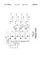
- FIG. 9is a schematic circuit diagram of a PWM controlling circuit in accordance with the present application.
- FIG. 10is a timing chart showing the operation of the PWM controlling circuit of FIG. 9.
- the PWM controlling circuit in accordance with the present inventioncomprises a signal generator 10, and two PWM controllers 50, 50'.
- the signal generator 10 of the present inventioncomprises an oscillator 11 having two outputs A and B, which respectively output synchronous signals with opposite phases, two inverters 13 and 14 connected with the outputs A and B, respectively, two RC delay networks 15, 16 connected with said two inverters 13, 14, respectively, and another two inverters 17, 18 connected with the two RC delay networks 15, 16, respectively.
- Respective outputs G, H of the two inverters 17 and 18are connected to trigger the two PWM controller 50, 50'.
- the PWM controllers 50, 50'can be conventional single output current mode PWM controllers, as found in the prior art.
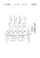
- the oscillator 11is composed of two diodes 113 and 114, two resistors 115 and 116 respectively connected in series with said two diodes 113 and 114, two inverters 111 and 112 connected with the diodes 113 and 114, and a capacitor 117.
- the two resistors 115 and 116construct RC delay loops with the capacitor 117, respectively.
- High and low transition points of the two outputs A and B of the oscillator 11can be adjusted by varying the resistances of the respective resistors 115 and 116, so that the respective durations of the positive and negative waveforms of each output of the oscillator 11 can be adjusted to be 1:1.
- the RC delay network 15consists of a diode 152, a resistor 151, and a capacitor 153.
- the RC delay network 16consists of a diode 162, a resistor 162, and a capacitor 163. Those portions of the signal generator 10 are all constructed with simple basic elements.
- the two outputs of the oscillator 11are indicated by A and B.
- the respective outputs of the two inverters 13 and 14are indicated by C and D
- the respective outputs of the RC delay networks 15 and 16are indicated by E and F
- the respective outputs of the inverters 17 and 18are indicated by G and H.
- the output signals at the nodes A and Bare synchronous rectangular waves with opposite phases.
- the two signalsthen pass through the inverters 13 and 14, respectively, to be buffered and isolated.
- the signals at nodes C and Dare inverted waveforms of the signals at nodes A and B, respectively.
- the inverted signalsthen pass through the RC delay networks 15 and 16, respectively.
- the RC delay networks 15 and 16function to charge rapidly as well as discharge smoothly. For example, when the signal at the node C goes to high, the terminal voltage of the capacitor 153 is charged rapidly to high level via the diode 152.
- the capacitor 153discharges smoothly via the resistor 151, so that the signal at node E (F) is of the waveform as shown in FIG. 10.
- the signals at the node Fis also formed by the same manner.
- the signals of the nodes E and Fpass through the inverters 17 and 18 to be formed as narrow-pulse signals (signals at the nodes G and H).
- the falling edges of the signals of the nodes G and Hare aligned with the falling edges of the signals of the nodes A and B, respectively. Accordingly, the two signals at the nodes G and H are synchronous but different in phase.
- the PWM controlling circuit in accordance with the present invention with the above constructioncan be implemented by simple and basic electronic elements with low cost. Furthermore, in this design, the duty cycle of each of the two PWM controller 50 and 50' can be adjusted individually. Therefore, the PWM controlling circuit in accordance with the present invention can overcome the limit of duty cycle for the prior art (the duty cycle for the conventional PWM controlling circuit 70 cannot exceed 50%).
Landscapes
- Engineering & Computer Science (AREA)
- Power Engineering (AREA)
- Dc-Dc Converters (AREA)
Abstract
Description
1. Field of the Invention
The present invention relates to a pulse width modulation (PWM) controlling circuit, more particularly, to a PWM controlling circuit for a switching power supply.
2. Description of Related Art
Various switching power supplies are available currently, which will be simply described in the following descriptions in conjunction with the accompanying drawings.
Referring to FIG. 1, which shows a conventional switching power supply, the switching power supply comprises aPWM controller 50, aswitching transistor 51, a transformer with four secondary windings and four rectifying and filtering circuits respectively connected with the secondary windings. The switching power supply of FIG. 1 has four output voltages V01-V04. Only the first output voltage V01 is fed back to thePWM controller 50 as a feed-back signal. Accordingly, only the first output voltage V01 is regulated, and the regulation of each of the other output voltages V02, V03 and V04 is poor.
Focusing on the above problem, an improved design is provided, as shown in FIG. 2. The structure of FIG. 2 is similar to that of FIG. 1 except that apost regulator 60 is provided to each of the outputs V02, V03 and V04. Although the provision of thepost regulators 60 can promote the regulation of the output voltages V02, V03 and V04, the conversion efficiency of eachpost regulator 60 is low resulting in a need for heat sink or the like, which occupy a lot of space.
FIG. 3 shows a conventional switching power supply, which is similar to that of FIG. 1 except that it utilizes twoPWM controllers 50, 50'. As in the switching power supply of FIG. 1, the output voltage V01 is fed back to thefirst PWM controller 50, while the output voltage V04 is fed back to the second PWM controller 50'. Accordingly, the output voltages V01 and V04 appear to be regulated, but the regulation of the output voltages V02 and V03 is still poor. In addition, ideally, the twoPWM controllers 50 and 50' should be exactly the same. However, this is impossible for the actual elements. Accordingly, oscillating frequencies of respective clock signals Clk1 and Clk2 of the respective twoPWM controllers 50 and 50' are always slightly different, thereby causing a phenomenon of beat frequency.
Referring to FIG. 4, another conventional switching power supply provided for improving the phenomenon of beat frequency mentioned above is shown. In the structure of FIG. 4, the twoPWM controllers 50 and 50' are connected with each other via asynchronization signal line 52, so that the twoPWM controllers 50 and 50' can be synchronous with each other. However, such a design results in serious electromagnetic interference. Since the two PWM controllers are in on and off statuses synchronously, causing considerable instantaneous current (di) is generated to flow in the circuit, as shown in FIG. 5. Accordingly, noises and electromagnetic interference are serious problems for such a design.
Referring to FIG. 6, a further conventional switching power supply is shown. In this structure, aclock generator 53 is used to generate two signals, which are synchronous but different in phase, as clock signals for the respective twoPWM controllers 50 and 50'. The twoPWM controllers 50 and 50' accordingly operate alternately, thus the instantaneous current (di) is low, as shown in FIG. 7.
In application, the twoPWM controllers 50, 50' and theclock generator 53 are integrated on a single IC, such as a dual current modePWM controlling circuit 70 of a series UCC1810-3810 produced by UNITRODE, as shown in FIG. 8. The IC of the dual current modePWM controlling circuit 70 comprises two output terminals OUT1, OUT2, anoscillator 71, a frequency divider 72, aninverter 73, two RS flip-flops buffers edge blanking devices 78. Outputs from the output terminals OUT1 and OUT2 are synchronous but different in phase.
However, the cost of such an IC is very high. In addition, the two outputs from the output terminals OUT1 and OUT2 are inverse in phase, and the duty cycles of the respective output cannot exceed 50%.
Accordingly, the present invention is directed toward overcoming the above problem of the conventional dual current mode PWM controlling circuit.
One object of the present invention is to provide a PWM controlling circuit with low cost.
Another object of the present invention is to provide a PWM controlling circuit, wherein the duty cycles of two outputs of the circuit can be set respectively, so that the duty cycles are not limited to 50%.
In accordance with one aspect of the present invention, the PWM controlling circuit comprises a signal generator and two PWM controllers. The signal generator comprises an oscillator, a plurality of inverters, and two RC delay networks. The oscillator and the inverters are composed of elementary elements, respectively, such as diodes, resistors, inverters and capacitors.
Other objects, advantages and novel features of the invention will become more apparent from the following detailed description when taken in conjunction with the accompanying drawings.
FIG. 1 shows a conventional switching power supply having a single PWM controller;
FIG. 2 shows a conventional switching power supply improved from the switching power supply of FIG. 1;
FIG. 3 shows a conventional switching power supply having two separate PWM controllers;
FIG. 4 shows a conventional switching power supply having two PWM controllers connected with each other;
FIG. 5 is a graph illustrating instantaneous current of the switching power supply of FIG. 4;
FIG. 6 shows a conventional switching power supply having a clock generator and two PWM controller;
FIG. 7 is a graph illustrating instantaneous current of the switching power supply of FIG. 6;
FIG. 8 is a circuit diagram of a conventional PWM controlling circuit;
FIG. 9 is a schematic circuit diagram of a PWM controlling circuit in accordance with the present application; and
FIG. 10 is a timing chart showing the operation of the PWM controlling circuit of FIG. 9.
Referring to FIG. 9, a PWM controlling circuit in accordance with the present invention is shown. As in the conventionalPWM controlling circuit 70, the PWM controlling circuit in accordance with the present invention comprises asignal generator 10, and twoPWM controllers 50, 50'. Thesignal generator 10 of the present invention comprises anoscillator 11 having two outputs A and B, which respectively output synchronous signals with opposite phases, twoinverters RC delay networks inverters inverters RC delay networks inverters PWM controller 50, 50'. It is noted that thePWM controllers 50, 50' can be conventional single output current mode PWM controllers, as found in the prior art.
As shown in the drawing, theoscillator 11 is composed of twodiodes resistors diodes inverters diodes capacitor 117. The tworesistors capacitor 117, respectively. High and low transition points of the two outputs A and B of theoscillator 11 can be adjusted by varying the resistances of therespective resistors oscillator 11 can be adjusted to be 1:1. TheRC delay network 15 consists of adiode 152, aresistor 151, and acapacitor 153. Likewise, theRC delay network 16 consists of adiode 162, aresistor 162, and acapacitor 163. Those portions of thesignal generator 10 are all constructed with simple basic elements.
The operation of thesignal generator 10 of the PWM controlling circuit in accordance with the present invention will be described in detail with reference to FIG. 10, as follows.
As mentioned above, the two outputs of theoscillator 11 are indicated by A and B. In addition, the respective outputs of the twoinverters RC delay networks inverters
As shown in FIG. 10, the output signals at the nodes A and B are synchronous rectangular waves with opposite phases. The two signals then pass through theinverters RC delay networks RC delay networks capacitor 153 is charged rapidly to high level via thediode 152. When the signal at the node: C transits to low, thecapacitor 153 discharges smoothly via theresistor 151, so that the signal at node E (F) is of the waveform as shown in FIG. 10. The signals at the node F is also formed by the same manner. The signals of the nodes E and F pass through theinverters
The PWM controlling circuit in accordance with the present invention with the above construction can be implemented by simple and basic electronic elements with low cost. Furthermore, in this design, the duty cycle of each of the twoPWM controller 50 and 50' can be adjusted individually. Therefore, the PWM controlling circuit in accordance with the present invention can overcome the limit of duty cycle for the prior art (the duty cycle for the conventionalPWM controlling circuit 70 cannot exceed 50%).
It is to be understood, however, that even though numerous characteristics and advantages of the present invention have been set forth in the foregoing description, together with details of the structure and function of the invention, the disclosure is illustrative only, and changes may be made in detail, especially in matters of shape, size, and arrangement of parts within the principles of the invention to the full extent indicated by the broad general meaning of the terms in which the appended claims are expressed.
Claims (6)
1. A pulse width modulation (PWM) controlling circuit comprising:
an oscillator having a first output and a second output for outputting two synchronous signals with a predetermined phase shift therebetween;
a first RC delay network and a second RC delay network respectively connected to said first and second outputs of said oscillator, said first and second RC delay networks generating two narrow pulses with said predetermined phase shift therebetween;
a first PWM controller connected with said first RC delay network to receive one of said two narrow pulses to be triggered thereby; and
a second PWM controller connected with said second RC delay network to receive the other of said two narrow pulses to be triggered thereby.
2. The PWM controlling circuit as claimed in claim 1, further comprising two inverters, one of which is connected between said first output of the oscillator and said first RC delay network, the other one is connected between said second output of the oscillator and said second RC delay network.
3. The PWM controlling circuit as claimed in claim 2, further comprising another two inverters, one of which is connected between said first RC delay network and said first PWM controller, and the other one is connected between said second RC delay network and said second PWM controller.
4. The PWM controlling circuit as claimed in claim 1, further comprising two inverters, one of which is connected between said first RC delay network and said first PWM controller, and the other one is connected between said second RC delay network and said second PWM controller.
5. The PWM controlling circuit as claimed in claim 1, wherein said oscillator comprises two diodes, two inverters, two resistors and a capacitor.
6. The PWM controlling circuit as claimed in claim 1, wherein each of said first and second RC delay networks comprises a diode, a capacitor and a resistor.
Priority Applications (1)
| Application Number | Priority Date | Filing Date | Title |
|---|---|---|---|
| US08/993,297US5901054A (en) | 1997-12-18 | 1997-12-18 | Pulse-width-modulation control circuit |
Applications Claiming Priority (1)
| Application Number | Priority Date | Filing Date | Title |
|---|---|---|---|
| US08/993,297US5901054A (en) | 1997-12-18 | 1997-12-18 | Pulse-width-modulation control circuit |
Publications (1)
| Publication Number | Publication Date |
|---|---|
| US5901054Atrue US5901054A (en) | 1999-05-04 |
Family
ID=25539358
Family Applications (1)
| Application Number | Title | Priority Date | Filing Date |
|---|---|---|---|
| US08/993,297Expired - LifetimeUS5901054A (en) | 1997-12-18 | 1997-12-18 | Pulse-width-modulation control circuit |
Country Status (1)
| Country | Link |
|---|---|
| US (1) | US5901054A (en) |
Cited By (51)
| Publication number | Priority date | Publication date | Assignee | Title |
|---|---|---|---|---|
| US6049706A (en) | 1998-10-21 | 2000-04-11 | Parkervision, Inc. | Integrated frequency translation and selectivity |
| US6061551A (en) | 1998-10-21 | 2000-05-09 | Parkervision, Inc. | Method and system for down-converting electromagnetic signals |
| US6061555A (en) | 1998-10-21 | 2000-05-09 | Parkervision, Inc. | Method and system for ensuring reception of a communications signal |
| US6091940A (en) | 1998-10-21 | 2000-07-18 | Parkervision, Inc. | Method and system for frequency up-conversion |
| US6370371B1 (en) | 1998-10-21 | 2002-04-09 | Parkervision, Inc. | Applications of universal frequency translation |
| US6542722B1 (en) | 1998-10-21 | 2003-04-01 | Parkervision, Inc. | Method and system for frequency up-conversion with variety of transmitter configurations |
| US6560301B1 (en) | 1998-10-21 | 2003-05-06 | Parkervision, Inc. | Integrated frequency translation and selectivity with a variety of filter embodiments |
| WO2003055060A1 (en)* | 2001-12-21 | 2003-07-03 | Bang & Olufsen Icepower A/S | Synchronized controlled oscillation modulator |
| EP1148627A3 (en)* | 2000-04-04 | 2003-11-05 | Artesyn Technologies, Inc. | A DC-to-DC power converter |
| US6694128B1 (en) | 1998-08-18 | 2004-02-17 | Parkervision, Inc. | Frequency synthesizer using universal frequency translation technology |
| US6704558B1 (en) | 1999-01-22 | 2004-03-09 | Parkervision, Inc. | Image-reject down-converter and embodiments thereof, such as the family radio service |
| US6704549B1 (en) | 1999-03-03 | 2004-03-09 | Parkvision, Inc. | Multi-mode, multi-band communication system |
| US20040095100A1 (en)* | 2002-11-19 | 2004-05-20 | Richard Thompson | Electrosurgical generator and method with voltage and frequency regulated high-voltage current mode power supply |
| US6765959B1 (en)* | 1998-06-05 | 2004-07-20 | Hitachi, Ltd. | Communication method of contactless ID card and integrated circuit used in communication method |
| US6813485B2 (en) | 1998-10-21 | 2004-11-02 | Parkervision, Inc. | Method and system for down-converting and up-converting an electromagnetic signal, and transforms for same |
| US6873836B1 (en) | 1999-03-03 | 2005-03-29 | Parkervision, Inc. | Universal platform module and methods and apparatuses relating thereto enabled by universal frequency translation technology |
| US6879817B1 (en) | 1999-04-16 | 2005-04-12 | Parkervision, Inc. | DC offset, re-radiation, and I/Q solutions using universal frequency translation technology |
| US6963734B2 (en) | 1999-12-22 | 2005-11-08 | Parkervision, Inc. | Differential frequency down-conversion using techniques of universal frequency translation technology |
| US6975848B2 (en) | 2002-06-04 | 2005-12-13 | Parkervision, Inc. | Method and apparatus for DC offset removal in a radio frequency communication channel |
| US7006805B1 (en) | 1999-01-22 | 2006-02-28 | Parker Vision, Inc. | Aliasing communication system with multi-mode and multi-band functionality and embodiments thereof, such as the family radio service |
| US7010286B2 (en) | 2000-04-14 | 2006-03-07 | Parkervision, Inc. | Apparatus, system, and method for down-converting and up-converting electromagnetic signals |
| US7010559B2 (en) | 2000-11-14 | 2006-03-07 | Parkervision, Inc. | Method and apparatus for a parallel correlator and applications thereof |
| US7027786B1 (en) | 1998-10-21 | 2006-04-11 | Parkervision, Inc. | Carrier and clock recovery using universal frequency translation |
| US7039372B1 (en) | 1998-10-21 | 2006-05-02 | Parkervision, Inc. | Method and system for frequency up-conversion with modulation embodiments |
| US7054296B1 (en) | 1999-08-04 | 2006-05-30 | Parkervision, Inc. | Wireless local area network (WLAN) technology and applications including techniques of universal frequency translation |
| US7072390B1 (en) | 1999-08-04 | 2006-07-04 | Parkervision, Inc. | Wireless local area network (WLAN) using universal frequency translation technology including multi-phase embodiments |
| US7072427B2 (en) | 2001-11-09 | 2006-07-04 | Parkervision, Inc. | Method and apparatus for reducing DC offsets in a communication system |
| US7082171B1 (en) | 1999-11-24 | 2006-07-25 | Parkervision, Inc. | Phase shifting applications of universal frequency translation |
| US7085335B2 (en) | 2001-11-09 | 2006-08-01 | Parkervision, Inc. | Method and apparatus for reducing DC offsets in a communication system |
| US7110435B1 (en) | 1999-03-15 | 2006-09-19 | Parkervision, Inc. | Spread spectrum applications of universal frequency translation |
| US7110444B1 (en) | 1999-08-04 | 2006-09-19 | Parkervision, Inc. | Wireless local area network (WLAN) using universal frequency translation technology including multi-phase embodiments and circuit implementations |
| US7209518B1 (en) | 2000-08-03 | 2007-04-24 | Mks Instruments, Inc. | Higher PWM resolution for switchmode power supply control |
| US7236754B2 (en) | 1999-08-23 | 2007-06-26 | Parkervision, Inc. | Method and system for frequency up-conversion |
| US7292835B2 (en) | 2000-01-28 | 2007-11-06 | Parkervision, Inc. | Wireless and wired cable modem applications of universal frequency translation technology |
| US7295826B1 (en) | 1998-10-21 | 2007-11-13 | Parkervision, Inc. | Integrated frequency translation and selectivity with gain control functionality, and applications thereof |
| US7321640B2 (en) | 2002-06-07 | 2008-01-22 | Parkervision, Inc. | Active polyphase inverter filter for quadrature signal generation |
| US7379883B2 (en) | 2002-07-18 | 2008-05-27 | Parkervision, Inc. | Networking methods and systems |
| US7454453B2 (en) | 2000-11-14 | 2008-11-18 | Parkervision, Inc. | Methods, systems, and computer program products for parallel correlation and applications thereof |
| US7460584B2 (en) | 2002-07-18 | 2008-12-02 | Parkervision, Inc. | Networking methods and systems |
| US7515896B1 (en) | 1998-10-21 | 2009-04-07 | Parkervision, Inc. | Method and system for down-converting an electromagnetic signal, and transforms for same, and aperture relationships |
| US7554508B2 (en) | 2000-06-09 | 2009-06-30 | Parker Vision, Inc. | Phased array antenna applications on universal frequency translation |
| US7693230B2 (en) | 1999-04-16 | 2010-04-06 | Parkervision, Inc. | Apparatus and method of differential IQ frequency up-conversion |
| US7724845B2 (en) | 1999-04-16 | 2010-05-25 | Parkervision, Inc. | Method and system for down-converting and electromagnetic signal, and transforms for same |
| US7773688B2 (en) | 1999-04-16 | 2010-08-10 | Parkervision, Inc. | Method, system, and apparatus for balanced frequency up-conversion, including circuitry to directly couple the outputs of multiple transistors |
| CN102468779A (en)* | 2010-11-08 | 2012-05-23 | 吕锦山 | Low current ripple power conversion circuit |
| US8295406B1 (en) | 1999-08-04 | 2012-10-23 | Parkervision, Inc. | Universal platform module for a plurality of communication protocols |
| US20130329475A1 (en)* | 2012-06-11 | 2013-12-12 | Raymond W. Rice | Systems and methods for protecting a switch mode power supply |
| US20170279383A1 (en)* | 2016-03-25 | 2017-09-28 | Mitsubishi Electric Corporation | Inverter control device and inverter control method |
| US11283433B2 (en)* | 2019-10-15 | 2022-03-22 | Webasto SE | Method for the PWM actuation of HV components |
| US11762447B2 (en) | 2021-12-22 | 2023-09-19 | Schweitzer Engineering Laboratories, Inc. | Power supply with boost stage to improve ride through performance |
| US12436176B2 (en)* | 2021-08-25 | 2025-10-07 | Richwave Technology Corp. | Device of measuring duty cycle and compensation circuit utilizing the same |
Citations (1)
| Publication number | Priority date | Publication date | Assignee | Title |
|---|---|---|---|---|
| US4473732A (en)* | 1981-01-07 | 1984-09-25 | General Electric Company | Power circuit for induction cooking |
- 1997
- 1997-12-18USUS08/993,297patent/US5901054A/ennot_activeExpired - Lifetime
Patent Citations (1)
| Publication number | Priority date | Publication date | Assignee | Title |
|---|---|---|---|---|
| US4473732A (en)* | 1981-01-07 | 1984-09-25 | General Electric Company | Power circuit for induction cooking |
Cited By (121)
| Publication number | Priority date | Publication date | Assignee | Title |
|---|---|---|---|---|
| US6765959B1 (en)* | 1998-06-05 | 2004-07-20 | Hitachi, Ltd. | Communication method of contactless ID card and integrated circuit used in communication method |
| US6694128B1 (en) | 1998-08-18 | 2004-02-17 | Parkervision, Inc. | Frequency synthesizer using universal frequency translation technology |
| US7937059B2 (en) | 1998-10-21 | 2011-05-03 | Parkervision, Inc. | Converting an electromagnetic signal via sub-sampling |
| US7389100B2 (en) | 1998-10-21 | 2008-06-17 | Parkervision, Inc. | Method and circuit for down-converting a signal |
| US6061555A (en) | 1998-10-21 | 2000-05-09 | Parkervision, Inc. | Method and system for ensuring reception of a communications signal |
| US6091940A (en) | 1998-10-21 | 2000-07-18 | Parkervision, Inc. | Method and system for frequency up-conversion |
| US6266518B1 (en) | 1998-10-21 | 2001-07-24 | Parkervision, Inc. | Method and system for down-converting electromagnetic signals by sampling and integrating over apertures |
| US6353735B1 (en) | 1998-10-21 | 2002-03-05 | Parkervision, Inc. | MDG method for output signal generation |
| US6370371B1 (en) | 1998-10-21 | 2002-04-09 | Parkervision, Inc. | Applications of universal frequency translation |
| US6421534B1 (en) | 1998-10-21 | 2002-07-16 | Parkervision, Inc. | Integrated frequency translation and selectivity |
| US6542722B1 (en) | 1998-10-21 | 2003-04-01 | Parkervision, Inc. | Method and system for frequency up-conversion with variety of transmitter configurations |
| US6560301B1 (en) | 1998-10-21 | 2003-05-06 | Parkervision, Inc. | Integrated frequency translation and selectivity with a variety of filter embodiments |
| US6580902B1 (en) | 1998-10-21 | 2003-06-17 | Parkervision, Inc. | Frequency translation using optimized switch structures |
| US8340618B2 (en) | 1998-10-21 | 2012-12-25 | Parkervision, Inc. | Method and system for down-converting an electromagnetic signal, and transforms for same, and aperture relationships |
| US8233855B2 (en) | 1998-10-21 | 2012-07-31 | Parkervision, Inc. | Up-conversion based on gated information signal |
| US6647250B1 (en) | 1998-10-21 | 2003-11-11 | Parkervision, Inc. | Method and system for ensuring reception of a communications signal |
| US6687493B1 (en) | 1998-10-21 | 2004-02-03 | Parkervision, Inc. | Method and circuit for down-converting a signal using a complementary FET structure for improved dynamic range |
| US8190108B2 (en) | 1998-10-21 | 2012-05-29 | Parkervision, Inc. | Method and system for frequency up-conversion |
| US6798351B1 (en) | 1998-10-21 | 2004-09-28 | Parkervision, Inc. | Automated meter reader applications of universal frequency translation |
| US6813485B2 (en) | 1998-10-21 | 2004-11-02 | Parkervision, Inc. | Method and system for down-converting and up-converting an electromagnetic signal, and transforms for same |
| US6836650B2 (en) | 1998-10-21 | 2004-12-28 | Parkervision, Inc. | Methods and systems for down-converting electromagnetic signals, and applications thereof |
| US8190116B2 (en) | 1998-10-21 | 2012-05-29 | Parker Vision, Inc. | Methods and systems for down-converting a signal using a complementary transistor structure |
| US8160534B2 (en) | 1998-10-21 | 2012-04-17 | Parkervision, Inc. | Applications of universal frequency translation |
| US7295826B1 (en) | 1998-10-21 | 2007-11-13 | Parkervision, Inc. | Integrated frequency translation and selectivity with gain control functionality, and applications thereof |
| US8019291B2 (en) | 1998-10-21 | 2011-09-13 | Parkervision, Inc. | Method and system for frequency down-conversion and frequency up-conversion |
| US7936022B2 (en) | 1998-10-21 | 2011-05-03 | Parkervision, Inc. | Method and circuit for down-converting a signal |
| US6061551A (en) | 1998-10-21 | 2000-05-09 | Parkervision, Inc. | Method and system for down-converting electromagnetic signals |
| US7245886B2 (en) | 1998-10-21 | 2007-07-17 | Parkervision, Inc. | Method and system for frequency up-conversion with modulation embodiments |
| US7076011B2 (en) | 1998-10-21 | 2006-07-11 | Parkervision, Inc. | Integrated frequency translation and selectivity |
| US7865177B2 (en) | 1998-10-21 | 2011-01-04 | Parkervision, Inc. | Method and system for down-converting an electromagnetic signal, and transforms for same, and aperture relationships |
| US7016663B2 (en) | 1998-10-21 | 2006-03-21 | Parkervision, Inc. | Applications of universal frequency translation |
| US7027786B1 (en) | 1998-10-21 | 2006-04-11 | Parkervision, Inc. | Carrier and clock recovery using universal frequency translation |
| US7039372B1 (en) | 1998-10-21 | 2006-05-02 | Parkervision, Inc. | Method and system for frequency up-conversion with modulation embodiments |
| US7050508B2 (en) | 1998-10-21 | 2006-05-23 | Parkervision, Inc. | Method and system for frequency up-conversion with a variety of transmitter configurations |
| US7826817B2 (en) | 1998-10-21 | 2010-11-02 | Parker Vision, Inc. | Applications of universal frequency translation |
| US7697916B2 (en) | 1998-10-21 | 2010-04-13 | Parkervision, Inc. | Applications of universal frequency translation |
| US7693502B2 (en) | 1998-10-21 | 2010-04-06 | Parkervision, Inc. | Method and system for down-converting an electromagnetic signal, transforms for same, and aperture relationships |
| US6049706A (en) | 1998-10-21 | 2000-04-11 | Parkervision, Inc. | Integrated frequency translation and selectivity |
| US7620378B2 (en) | 1998-10-21 | 2009-11-17 | Parkervision, Inc. | Method and system for frequency up-conversion with modulation embodiments |
| US7308242B2 (en) | 1998-10-21 | 2007-12-11 | Parkervision, Inc. | Method and system for down-converting and up-converting an electromagnetic signal, and transforms for same |
| US7321735B1 (en) | 1998-10-21 | 2008-01-22 | Parkervision, Inc. | Optical down-converter using universal frequency translation technology |
| US7218907B2 (en) | 1998-10-21 | 2007-05-15 | Parkervision, Inc. | Method and circuit for down-converting a signal |
| US7529522B2 (en) | 1998-10-21 | 2009-05-05 | Parkervision, Inc. | Apparatus and method for communicating an input signal in polar representation |
| US7376410B2 (en) | 1998-10-21 | 2008-05-20 | Parkervision, Inc. | Methods and systems for down-converting a signal using a complementary transistor structure |
| US7515896B1 (en) | 1998-10-21 | 2009-04-07 | Parkervision, Inc. | Method and system for down-converting an electromagnetic signal, and transforms for same, and aperture relationships |
| US7194246B2 (en) | 1998-10-21 | 2007-03-20 | Parkervision, Inc. | Methods and systems for down-converting a signal using a complementary transistor structure |
| US7006805B1 (en) | 1999-01-22 | 2006-02-28 | Parker Vision, Inc. | Aliasing communication system with multi-mode and multi-band functionality and embodiments thereof, such as the family radio service |
| US6704558B1 (en) | 1999-01-22 | 2004-03-09 | Parkervision, Inc. | Image-reject down-converter and embodiments thereof, such as the family radio service |
| US7483686B2 (en) | 1999-03-03 | 2009-01-27 | Parkervision, Inc. | Universal platform module and methods and apparatuses relating thereto enabled by universal frequency translation technology |
| US6873836B1 (en) | 1999-03-03 | 2005-03-29 | Parkervision, Inc. | Universal platform module and methods and apparatuses relating thereto enabled by universal frequency translation technology |
| US6704549B1 (en) | 1999-03-03 | 2004-03-09 | Parkvision, Inc. | Multi-mode, multi-band communication system |
| US7110435B1 (en) | 1999-03-15 | 2006-09-19 | Parkervision, Inc. | Spread spectrum applications of universal frequency translation |
| US7599421B2 (en) | 1999-03-15 | 2009-10-06 | Parkervision, Inc. | Spread spectrum applications of universal frequency translation |
| US7894789B2 (en) | 1999-04-16 | 2011-02-22 | Parkervision, Inc. | Down-conversion of an electromagnetic signal with feedback control |
| US7190941B2 (en) | 1999-04-16 | 2007-03-13 | Parkervision, Inc. | Method and apparatus for reducing DC offsets in communication systems using universal frequency translation technology |
| US8594228B2 (en) | 1999-04-16 | 2013-11-26 | Parkervision, Inc. | Apparatus and method of differential IQ frequency up-conversion |
| US7272164B2 (en) | 1999-04-16 | 2007-09-18 | Parkervision, Inc. | Reducing DC offsets using spectral spreading |
| US7693230B2 (en) | 1999-04-16 | 2010-04-06 | Parkervision, Inc. | Apparatus and method of differential IQ frequency up-conversion |
| US8224281B2 (en) | 1999-04-16 | 2012-07-17 | Parkervision, Inc. | Down-conversion of an electromagnetic signal with feedback control |
| US7224749B2 (en) | 1999-04-16 | 2007-05-29 | Parkervision, Inc. | Method and apparatus for reducing re-radiation using techniques of universal frequency translation technology |
| US8077797B2 (en) | 1999-04-16 | 2011-12-13 | Parkervision, Inc. | Method, system, and apparatus for balanced frequency up-conversion of a baseband signal |
| US8036304B2 (en) | 1999-04-16 | 2011-10-11 | Parkervision, Inc. | Apparatus and method of differential IQ frequency up-conversion |
| US8223898B2 (en) | 1999-04-16 | 2012-07-17 | Parkervision, Inc. | Method and system for down-converting an electromagnetic signal, and transforms for same |
| US7724845B2 (en) | 1999-04-16 | 2010-05-25 | Parkervision, Inc. | Method and system for down-converting and electromagnetic signal, and transforms for same |
| US7539474B2 (en) | 1999-04-16 | 2009-05-26 | Parkervision, Inc. | DC offset, re-radiation, and I/Q solutions using universal frequency translation technology |
| US6879817B1 (en) | 1999-04-16 | 2005-04-12 | Parkervision, Inc. | DC offset, re-radiation, and I/Q solutions using universal frequency translation technology |
| US7773688B2 (en) | 1999-04-16 | 2010-08-10 | Parkervision, Inc. | Method, system, and apparatus for balanced frequency up-conversion, including circuitry to directly couple the outputs of multiple transistors |
| US7929638B2 (en) | 1999-04-16 | 2011-04-19 | Parkervision, Inc. | Wireless local area network (WLAN) using universal frequency translation technology including multi-phase embodiments |
| US8229023B2 (en) | 1999-04-16 | 2012-07-24 | Parkervision, Inc. | Wireless local area network (WLAN) using universal frequency translation technology including multi-phase embodiments |
| US7054296B1 (en) | 1999-08-04 | 2006-05-30 | Parkervision, Inc. | Wireless local area network (WLAN) technology and applications including techniques of universal frequency translation |
| US7110444B1 (en) | 1999-08-04 | 2006-09-19 | Parkervision, Inc. | Wireless local area network (WLAN) using universal frequency translation technology including multi-phase embodiments and circuit implementations |
| US7653145B2 (en) | 1999-08-04 | 2010-01-26 | Parkervision, Inc. | Wireless local area network (WLAN) using universal frequency translation technology including multi-phase embodiments and circuit implementations |
| US8295406B1 (en) | 1999-08-04 | 2012-10-23 | Parkervision, Inc. | Universal platform module for a plurality of communication protocols |
| US7072390B1 (en) | 1999-08-04 | 2006-07-04 | Parkervision, Inc. | Wireless local area network (WLAN) using universal frequency translation technology including multi-phase embodiments |
| US7236754B2 (en) | 1999-08-23 | 2007-06-26 | Parkervision, Inc. | Method and system for frequency up-conversion |
| US7546096B2 (en) | 1999-08-23 | 2009-06-09 | Parkervision, Inc. | Frequency up-conversion using a harmonic generation and extraction module |
| US7379515B2 (en) | 1999-11-24 | 2008-05-27 | Parkervision, Inc. | Phased array antenna applications of universal frequency translation |
| US7082171B1 (en) | 1999-11-24 | 2006-07-25 | Parkervision, Inc. | Phase shifting applications of universal frequency translation |
| US6963734B2 (en) | 1999-12-22 | 2005-11-08 | Parkervision, Inc. | Differential frequency down-conversion using techniques of universal frequency translation technology |
| US7292835B2 (en) | 2000-01-28 | 2007-11-06 | Parkervision, Inc. | Wireless and wired cable modem applications of universal frequency translation technology |
| EP1148627A3 (en)* | 2000-04-04 | 2003-11-05 | Artesyn Technologies, Inc. | A DC-to-DC power converter |
| US7386292B2 (en) | 2000-04-14 | 2008-06-10 | Parkervision, Inc. | Apparatus, system, and method for down-converting and up-converting electromagnetic signals |
| US7010286B2 (en) | 2000-04-14 | 2006-03-07 | Parkervision, Inc. | Apparatus, system, and method for down-converting and up-converting electromagnetic signals |
| US7218899B2 (en) | 2000-04-14 | 2007-05-15 | Parkervision, Inc. | Apparatus, system, and method for up-converting electromagnetic signals |
| US8295800B2 (en) | 2000-04-14 | 2012-10-23 | Parkervision, Inc. | Apparatus and method for down-converting electromagnetic signals by controlled charging and discharging of a capacitor |
| US7496342B2 (en) | 2000-04-14 | 2009-02-24 | Parkervision, Inc. | Down-converting electromagnetic signals, including controlled discharge of capacitors |
| US7107028B2 (en) | 2000-04-14 | 2006-09-12 | Parkervision, Inc. | Apparatus, system, and method for up converting electromagnetic signals |
| US7822401B2 (en) | 2000-04-14 | 2010-10-26 | Parkervision, Inc. | Apparatus and method for down-converting electromagnetic signals by controlled charging and discharging of a capacitor |
| US7554508B2 (en) | 2000-06-09 | 2009-06-30 | Parker Vision, Inc. | Phased array antenna applications on universal frequency translation |
| US7209518B1 (en) | 2000-08-03 | 2007-04-24 | Mks Instruments, Inc. | Higher PWM resolution for switchmode power supply control |
| US7010559B2 (en) | 2000-11-14 | 2006-03-07 | Parkervision, Inc. | Method and apparatus for a parallel correlator and applications thereof |
| US7454453B2 (en) | 2000-11-14 | 2008-11-18 | Parkervision, Inc. | Methods, systems, and computer program products for parallel correlation and applications thereof |
| US7433910B2 (en) | 2000-11-14 | 2008-10-07 | Parkervision, Inc. | Method and apparatus for the parallel correlator and applications thereof |
| US7991815B2 (en) | 2000-11-14 | 2011-08-02 | Parkervision, Inc. | Methods, systems, and computer program products for parallel correlation and applications thereof |
| US7233969B2 (en) | 2000-11-14 | 2007-06-19 | Parkervision, Inc. | Method and apparatus for a parallel correlator and applications thereof |
| US7072427B2 (en) | 2001-11-09 | 2006-07-04 | Parkervision, Inc. | Method and apparatus for reducing DC offsets in a communication system |
| US7085335B2 (en) | 2001-11-09 | 2006-08-01 | Parkervision, Inc. | Method and apparatus for reducing DC offsets in a communication system |
| US8446994B2 (en) | 2001-11-09 | 2013-05-21 | Parkervision, Inc. | Gain control in a communication channel |
| US7653158B2 (en) | 2001-11-09 | 2010-01-26 | Parkervision, Inc. | Gain control in a communication channel |
| US7119629B2 (en) | 2001-12-21 | 2006-10-10 | Bang & Olufsen Icepower A/S | Synchronized controlled oscillation modulator |
| CN100444519C (en)* | 2001-12-21 | 2008-12-17 | 邦及奥卢夫森公司 | Synchronous controlled oscillation modulator |
| US20050068121A1 (en)* | 2001-12-21 | 2005-03-31 | Karsten Nielsen | Synchronized controlled oscillation modulator |
| AU2002366893B2 (en)* | 2001-12-21 | 2007-07-26 | Bang & Olufsen Icepower A/S | Synchronized controlled oscillation modulator |
| WO2003055060A1 (en)* | 2001-12-21 | 2003-07-03 | Bang & Olufsen Icepower A/S | Synchronized controlled oscillation modulator |
| US6975848B2 (en) | 2002-06-04 | 2005-12-13 | Parkervision, Inc. | Method and apparatus for DC offset removal in a radio frequency communication channel |
| US7321640B2 (en) | 2002-06-07 | 2008-01-22 | Parkervision, Inc. | Active polyphase inverter filter for quadrature signal generation |
| US8407061B2 (en) | 2002-07-18 | 2013-03-26 | Parkervision, Inc. | Networking methods and systems |
| US7460584B2 (en) | 2002-07-18 | 2008-12-02 | Parkervision, Inc. | Networking methods and systems |
| US7379883B2 (en) | 2002-07-18 | 2008-05-27 | Parkervision, Inc. | Networking methods and systems |
| US8160196B2 (en) | 2002-07-18 | 2012-04-17 | Parkervision, Inc. | Networking methods and systems |
| US6939347B2 (en) | 2002-11-19 | 2005-09-06 | Conmed Corporation | Electrosurgical generator and method with voltage and frequency regulated high-voltage current mode power supply |
| US20040095100A1 (en)* | 2002-11-19 | 2004-05-20 | Richard Thompson | Electrosurgical generator and method with voltage and frequency regulated high-voltage current mode power supply |
| CN102468779A (en)* | 2010-11-08 | 2012-05-23 | 吕锦山 | Low current ripple power conversion circuit |
| US20130329475A1 (en)* | 2012-06-11 | 2013-12-12 | Raymond W. Rice | Systems and methods for protecting a switch mode power supply |
| AU2013274601B2 (en)* | 2012-06-11 | 2015-03-19 | Schweitzer Engineering Laboratories, Inc. | Systems and methods for protecting a switch mode power supply |
| US8988903B2 (en)* | 2012-06-11 | 2015-03-24 | Schweitzer Engineering Laboratories, Inc. | Systems and methods for protecting a switch mode power supply |
| US20170279383A1 (en)* | 2016-03-25 | 2017-09-28 | Mitsubishi Electric Corporation | Inverter control device and inverter control method |
| US10050569B2 (en)* | 2016-03-25 | 2018-08-14 | Mitsubishi Electric Corporation | Inverter control device and inverter control method |
| US11283433B2 (en)* | 2019-10-15 | 2022-03-22 | Webasto SE | Method for the PWM actuation of HV components |
| US12436176B2 (en)* | 2021-08-25 | 2025-10-07 | Richwave Technology Corp. | Device of measuring duty cycle and compensation circuit utilizing the same |
| US11762447B2 (en) | 2021-12-22 | 2023-09-19 | Schweitzer Engineering Laboratories, Inc. | Power supply with boost stage to improve ride through performance |
Similar Documents
| Publication | Publication Date | Title |
|---|---|---|
| US5901054A (en) | Pulse-width-modulation control circuit | |
| EP0096370B1 (en) | Power supply device | |
| CN102044972B (en) | Control equipment for resonant converters | |
| US4290101A (en) | N Phase digital inverter | |
| EP0903841B1 (en) | Ac/ac converter | |
| US8102157B2 (en) | Multi-output power supply device having charge pump circuit | |
| US4513361A (en) | Multi-phase DC-to-AC and DC-to-DC boost converter | |
| EP0605752A2 (en) | Switching power supply | |
| US5481447A (en) | Switched capacitance voltage multiplier with commutation | |
| JPH09509557A (en) | Phased array power processor and its operating method | |
| JP2000201474A (en) | Method and circuit for controlling timing and slope compensation in switching regulator | |
| JPH04364359A (en) | High-efficiency power converter with synchronous switching system | |
| TW201208259A (en) | Regulator and synchronized pulse generator thereof | |
| US5640082A (en) | Duty cycle controlled switch variable capacitor circuit | |
| WO2020211059A1 (en) | Multi-phase signal control circuit and method | |
| US6744647B2 (en) | Parallel connected converters apparatus and methods using switching cycle with energy holding state | |
| US11848616B2 (en) | Three-phase LLC power supply circuit for high voltage bus input | |
| JP3574849B2 (en) | DC-DC converter device | |
| JP2004096816A (en) | Multi-output DC-DC converter | |
| US4253139A (en) | Power conversion and regulation system | |
| US20050242858A1 (en) | Apparatus and method for synchronized distributed pulse width modulation waveforms in microprocessor and digital signal processing devices | |
| US5892352A (en) | Synchronization of the switching action of hysteresis current controlled parallel connected power electronics systems | |
| US5793628A (en) | Multi-phase pulse-width-modulation power converter | |
| US7019986B2 (en) | Power conversion apparatus and dead time generator | |
| JP2004104645A (en) | Triangular wave generating device, pulse width modulation signal generating device and external synchronization/internal synchronization/asynchronization switching device |
Legal Events
| Date | Code | Title | Description |
|---|---|---|---|
| AS | Assignment | Owner name:CHUN SHAN INSTITUTE OF SCIENCE AND TECHNOLOGY, TAI Free format text:ASSIGNMENT OF ASSIGNORS INTEREST;ASSIGNORS:LEU, CHING-SHAN;LIU, WUEICHAN;HWANG, JEANG;REEL/FRAME:009074/0609 Effective date:19970920 | |
| STCF | Information on status: patent grant | Free format text:PATENTED CASE | |
| FPAY | Fee payment | Year of fee payment:4 | |
| FPAY | Fee payment | Year of fee payment:8 | |
| FPAY | Fee payment | Year of fee payment:12 | |
| AS | Assignment | Owner name:NATIONAL CHUNG SHAN INSTITUTE OF SCIENCE AND TECHN Free format text:CHANGE OF NAME;ASSIGNOR:CHUNG-SHAN INSTITUTE OF SCIENCE AND TECHNOLOGY;REEL/FRAME:035453/0240 Effective date:20140129 |